International Journal of Engineering Research and Development
e-ISSN: 2278-067X, p-ISSN: 2278-800X, www.ijerd.com
Volume 9, Issue 8 (January 2014), PP. 50-63
50
Geo-technical Assessment of Foundation Conditions of a Site in
Ubima, Ikwerre Local Government Area, Rivers State, Nigeria
H.O Nwankwoala1 and T. Warmate
2
1Department of Geology, College of Natural and Applied Sciences, University of Port Harcourt, Nigeria
2 Geostrat International Services Limited, No.14 Mannila Pepple Street, D-Line, Port Harcourt, Nigeria
Abstract:-This study aims at establishing the sub-soil types and profile to ascertain the geotechnical
characteristics of the underlying soils in Ubima in Ikwerre Local Government Area of Rivers State, Nigeria and
recommend appropriate foundation design and construction of projects in the area. Borings were accomplished
using a percussion rig with the aid of augers. Representative samples were analyzed in the laboratory in
accordance with relevant geotechnical engineering standards. The study revealed that the soil deposits within the
depths explored are characterized by a near-surface deposit of firm to stiff sandy clay. Beneath is a medium
dense sandy layer. The water table was at 11m below ground level. The thickness of this deposit, as confirmed
by both the borings and the cone resistance soundings varies within 9m. The clay is mainly of moderate
compressibilty with Mv values > 0.15m2/MN and Brownish in colour, with average Cone Penetrometer Test
(CPT) value of 10kg/cm2. The allowable bearing capacity profile of the sub-surface shows moderate bearing
capacity characteristics (1.5m: 132KN/m2). Settlement predictions based on a loading of 150KN/m
2 indicated a
settlement of 10mm. For design purposes, undrained cohesion of 50kPa, angle of internal friction of zero and
saturated unit weight of 18kN/m3 are suggested for this layer. Underlying the lower clay is a layer of
predominantly well sorted, medium dense sand. About 11m of the sand deposit was proved. Practically, for
design purpose, mean angle of internal friction of 31o and cohesion zero are recommended for the sand layer.
Following the results of this study, it is recommended that shallow foundation and placement of raft/mat
foundations are viable options in the area.
Keywords:- Geotechnical Engineering, Sub-soil, Ubima, Niger Delta.
I. INTRODUCTION The need for adequate and reliable geotechnical characterization of sub-soils is very important. This is
because the impact of the imposed load is exacerbated by the thickness and consistency of the compressible
layer. This, in addition to other intrinsic factors contributes to the failure of civil engineering structures
(Youdeowei & Nwankwoala, 2013; Amadi et al, 2012). For the purpose of generating relevant data inputs for
the design and construction of foundations for proposed structures, it is imperative that site (s) be geo-
technically characterized through sub-soil investigation. The geotechnical evaluation of subsoil condition of a
site is necessary in generating relevant data inputs for the design and construction of foundations for proposed
structures. The knowledge of the geotechnical characteristics of Ubima in Ikwerre Local Government Area of
Rivers State, Nigeria is very desirable for design and construction of foundation of civil engineering structures
in order to minimize adverse effects and prevention of post construction problems. Some studies have been
carried out on geotechnical properties of the subsoils generally (Ngah & Nwankwoala, 2013; Nwankwoala &
Amadi, 2013; Youdeowei & Nwankwoala, 2013; Oke & Amadi, 2008; Oke et al., 2009).
Geologically, the site (Fig. 1) in Ubima in Ikwerre Local Government Area of Rivers State, Nigeria is
underlain by the Coastal Plain sands, which in this area is overlain by soft-firm silty clay sediments belonging to
the Pleistocenic Formation. The general geology of the area essentially reflects the influence of movements of
rivers, in the Niger delta and their search for lines of flow to the sea with consequent deposition of transported
sediments. In broad terms, the area may be considered flat. The surface deposits in the area comprised silty-
clays. The near surface silty clays are subjected to mild desiccation during the dry season. Substantial seasonal
variations in moisture are expected in the area. This could result in some false enhancement of strength in the
dry season. The sandy layers underlying the top clay are predominantly medium to coarse in grain sizes, fairly
well graded and found to exist in various states of compaction.
Generally, in the Niger Delta geotechnical data on the underlying soils are needed for the design of
suitable foundation for structures (Ngah & Nwankwoala, 2013). This study therefore, is aimed at establishing
significant subsoil types and profile, determination of the stratigraphy of the superficial deposits underlying the
site, determination of relevant engineering characteristics of the deposits for appropriate foundation design, the

Geo-technical Assessment of Foundation Conditions of a Site in Ubima, Ikwerre Local Government…
51
investigation/characterization of the geotechnical properties of all such sub-soils to generate the required data
relevant to the foundation design and construction of structures as well as foundation recommendation for
proposed structures in the area.
Fig. 1: Map of Ikwerre LGA Showing the Study Area - Ubima
II. METHODS OF STUDY Cone Penetration Testing (CPT): Hydraulically operated, GMF type, static penetrometer of 100KN
capacity was used in the cone resistance soundings. Mechanical mantle cone with friction jacket was used in the
operation. Discontinuous sounding procedure was adopted in the test. The cone in its retracted position is first
forced into the ground a distance of 10cm by the application of force to the outer sounding tubes. The cone was
then pushed out a distance of about 4cm by the application of force to the inner rods only and the magnitude of
the force required to achieve this, was measured on the pressure gauges and recorded and this is the cone
resistance.
Soil Borings: Conventional boring method which consists of the use of the light shell and auger hand
rig were used in the boring operation. During the boring operations, disturbed samples were regularly collected
at depths of 0.75m intervals and also when change of soil type was noticed. Undisturbed cohesive soil samples
will be retrieved from the boreholes with conventional open-tube sampler 100mm in diameter and 450mm in
length. The open-tube sampler consists essentially of a lower end and upper end screwed into a drive head
which is attached to the rods of the rig. The head has an overdrive space and incorporates a non-return valve to

Geo-technical Assessment of Foundation Conditions of a Site in Ubima, Ikwerre Local Government…
52
permit the escape of air or water as the samples enters the tube. The sampler was driven into the soil by
dynamic means using a drop hammer. On withdrawal of the sampler, the non-return valve assists in retaining
the sample in the tube. All samples recovered from the boreholes were examined, identified and roughly
classified in the field.
Standard Penetration Tests (SPT) were performed every 1.5m advance through cohesionless soils. The
main objective of this test is to assess the relative densities of the cohesionless soils penetrated. Also, a 50mm
diameter split spoon sampler was driven 450mm into the soil with a 63.5kg hammer falling freely a distance of
760mm. The sampler was driven into the soil in two stages. The initial 150mm penetration of the sampler is the
seating drive and the last 300mm penetration, the test drive. The number of blows required to effect the last
300mm penetration below the seating drive provide an indication of the relative density of the cohesionless soil
stratum tested. This is also referred to as the N-value. The penetration resistance in blow counts with depths are
indicated on borehole logs.
III. BEARING CAPACITY The conventional method of foundation design is based on the concept of bearing capacity or allowable
bearing pressure of the soil. The bearing capacity is defined as the load or pressure developed under the
foundation without introducing damaging movements in the foundation and in the superstructure supported on
the foundation (Peck et al, 1973). Damaging movements may result from foundation failure or excessive
settlement. The two criteria used in the design of foundation are therefore (i) Determination of bearing capacity
of soil and the selection of adequate factor of safety, usually not less than 2.5 (ii) Estimating the settlement
under the expected load and comparison with the permissible settlement.
IV. CHOICE OF PARAMETERS In clays, the ultimate bearing capacity of spread foundation is calculated using total stress parameters.
This gives the end-of-construction case, which is the worst condition, and allows the design to be based on
undrained shear strength tests. The bearing capacity analysis for the underlying soils is limited to the near
surface sandy clay. In general, the sandy clay is partially saturated and when tested in unconsolidated and
undrained conditions, exhibits both cohesion and angle of internal friction for its shear strength characteristics.
However, the frictional component of shear strength is neglected for the clay encountered within normal
founding depths for shallow foundations when estimating ultimate bearing pressures for the clay. Undrained
cohesion of 50kPa and angle of internal friction of 1 are adopted for the bearing capacity analysis.
V. RESULTS AND DISCUSSION The study revealed that the soil deposits within the depths explored are characterized by a near-surface
deposit of firm to stiff sandy clay. Beneath is a medium dense sandy layer. The water table was at 11m below
ground level. The thickness of this deposit, as confirmed by both the borings and the cone resistance soundings
varies within 9m. The clay is mainly of moderate compressibilty with Mv values > 0.15m2/MN and Brownish in
colour, with average Cone Penetrometer Test (CPT) value of 10kg/cm2. The allowable bearing capacity profile
of the sub-surface shows moderate bearing capacity characteristics (1.5m: 132KN/m2). Settlement predictions
based on a loading of 150KN/m2 indicated a settlement of 10mm. For design purposes, undrained cohesion of
50kPa, angle of internal friction of zero and saturated unit weight of 18kN/m3 are suggested for this layer.
Underlying the lower clay is a layer of predominantly well sorted, medium dense sand. About 11m of the sand
deposit was proved. Practically, for design purpose, mean angle of internal friction of 31o and cohesion zero are
suggested for the sand layer. Fig. 2 and 3 shows the variation of settlement with foundation pressure while Fig.
4 & 5 shows the relationship of void ratio versus pressure. Fig.6, 7 & 8 shows the Mohr Circle of the Quick
Undrained Triaxial Test results for BH -1, BH-2 and BH-3, respectively while Fig. 9 & 10 shows the plots
showing Stress- Strain relationships. Fig. 11 shows the Cone Penetration Profiles (CPT) for BH-1, and BH-2,
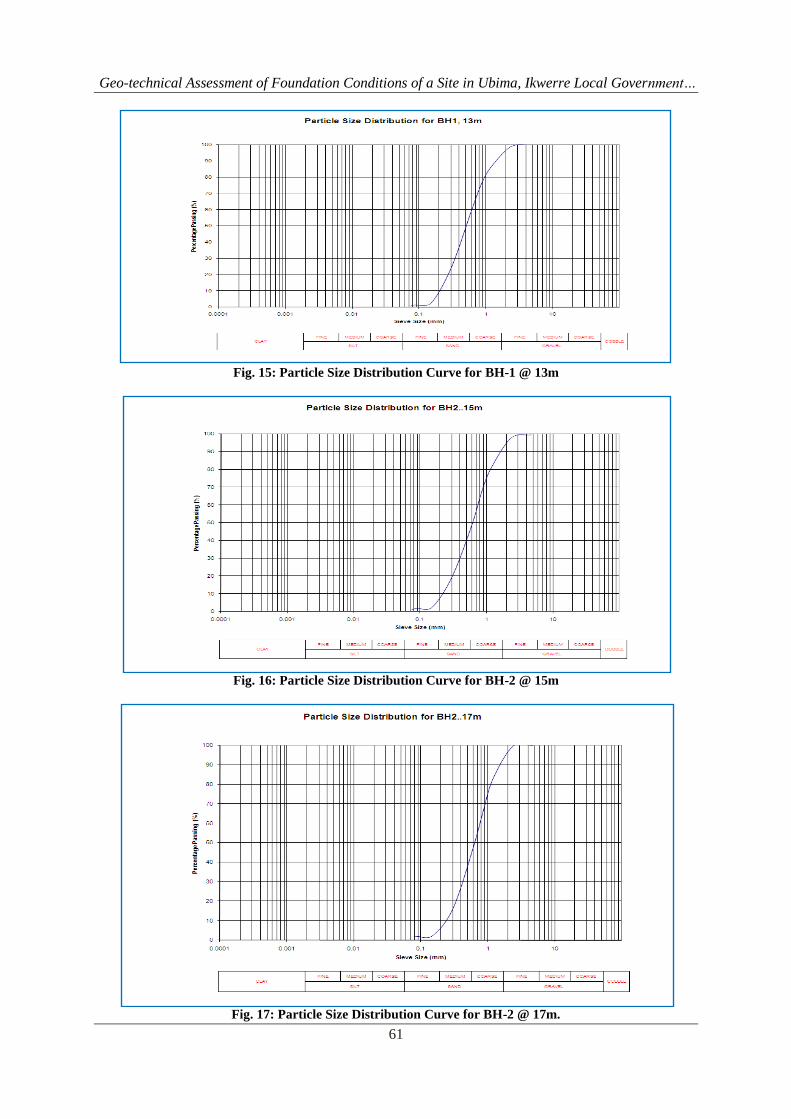
respectively. Fig. 13 & 14 shows the Borehole Logs for BH-1 & BH-2 while Fig. 15, 16 & 17 gives the Particle
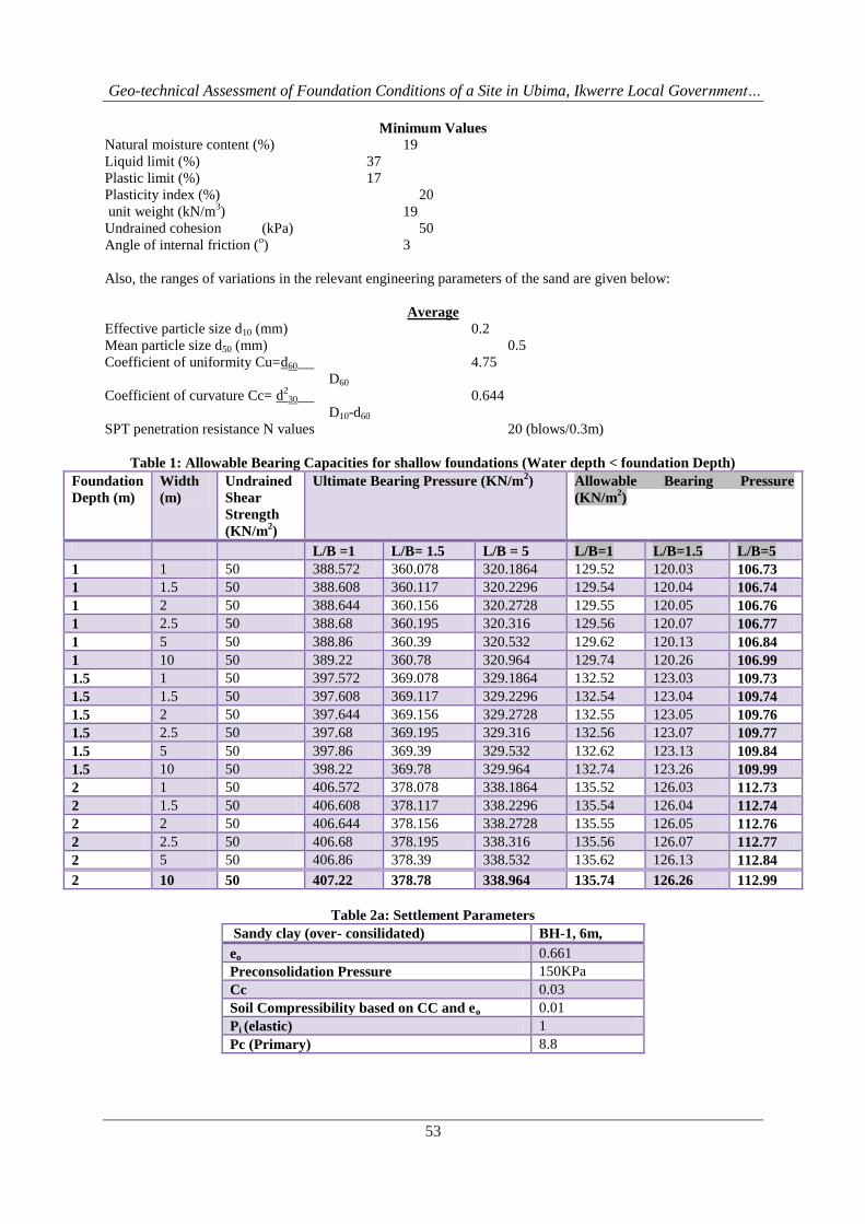
Size Distribution Curves for BH-1 @ 13m and BH-2 @ 15m, BH-2 @ 17m, respectively. Table 1 shows the
allowable bearing capacities for shallow foundation while Table 2a, b shows Settlement parameters and
Computed Rate of Settlements. Table 3a & Table 3b also shows the settlement parameters while Table 4 shows
Triaxial @ BH -1, 1.5m, Table 5: Triaxial @ BH -1, 3m and Table 6: Triaxial BH -1, 6m, respectively.
The ranges of variations in the relevant index and engineering parameters of the clay are summarized below:
Geo-technical Assessment of Foundation Conditions of a Site in Ubima, Ikwerre Local Government…
53
Minimum Values
Natural moisture content (%) 19
Liquid limit (%) 37
Plastic limit (%) 17
Plasticity index (%) 20
unit weight (kN/m3) 19
Undrained cohesion (kPa) 50
Angle of internal friction (o) 3
Also, the ranges of variations in the relevant engineering parameters of the sand are given below:
Average
Effective particle size d10 (mm) 0.2
Mean particle size d50 (mm) 0.5
Coefficient of uniformity Cu=d60 4.75
D60
Coefficient of curvature Cc= d2
30 0.644
D10-d60
SPT penetration resistance N values 20 (blows/0.3m)
Table 1: Allowable Bearing Capacities for shallow foundations (Water depth < foundation Depth)
Foundation
Depth (m)
Width
(m)
Undrained
Shear
Strength
(KN/m2)
Ultimate Bearing Pressure (KN/m2) Allowable Bearing Pressure
(KN/m2)
L/B =1 L/B= 1.5 L/B = 5 L/B=1 L/B=1.5 L/B=5
1 1 50 388.572 360.078 320.1864 129.52 120.03 106.73
1 1.5 50 388.608 360.117 320.2296 129.54 120.04 106.74
1 2 50 388.644 360.156 320.2728 129.55 120.05 106.76
1 2.5 50 388.68 360.195 320.316 129.56 120.07 106.77
1 5 50 388.86 360.39 320.532 129.62 120.13 106.84
1 10 50 389.22 360.78 320.964 129.74 120.26 106.99
1.5 1 50 397.572 369.078 329.1864 132.52 123.03 109.73
1.5 1.5 50 397.608 369.117 329.2296 132.54 123.04 109.74
1.5 2 50 397.644 369.156 329.2728 132.55 123.05 109.76
1.5 2.5 50 397.68 369.195 329.316 132.56 123.07 109.77
1.5 5 50 397.86 369.39 329.532 132.62 123.13 109.84
1.5 10 50 398.22 369.78 329.964 132.74 123.26 109.99
2 1 50 406.572 378.078 338.1864 135.52 126.03 112.73
2 1.5 50 406.608 378.117 338.2296 135.54 126.04 112.74
2 2 50 406.644 378.156 338.2728 135.55 126.05 112.76
2 2.5 50 406.68 378.195 338.316 135.56 126.07 112.77
2 5 50 406.86 378.39 338.532 135.62 126.13 112.84
2 10 50 407.22 378.78 338.964 135.74 126.26 112.99
Table 2a: Settlement Parameters
Sandy clay (over- consilidated) BH-1, 6m,
eo 0.661
Preconsolidation Pressure 150KPa
Cc 0.03
Soil Compressibility based on CC and eo 0.01
Pi (elastic) 1
Pc (Primary) 8.8

Geo-technical Assessment of Foundation Conditions of a Site in Ubima, Ikwerre Local Government…
54
Table 2b: Computed Rate of Settlements
Rate of Settlements Years
T50 0.02
T90 0.1
Table 3a: Settlement Parameters
Clay BH-1, 1.5m(Over consolidated)
eo 0.661
Pre-consolidation Pressure 120KPa
Cc 0.04
Soil Compressibility based on CC and eo 0.03
Pi (elastic) 1
Pc (Primary) 9
Table 3b: Computed Rate of Settlements
Rate of Settlements Years
T50 0.02
T90 0.1
Table 4: Triaxial @ BH -1, 1.5m
Minor Principal Stress
100KN/m2 300KN/m
2
Deviator Stress
138KN/m2
158KN/m2
Major Principal Stress
238KN/m2
458KN/m2
Table 5: Triaxial @ BH -1, 3m
Minor Principal Stress
100KN/m2 300KN/m
2
Deviator Stress
130KN/m2
157KN/m2
Major Principal Stress
230KN/m2
457KN/m2
Table 6: Triaxial BH -1, 6m
Minor Principal Stress
100KN/m2 300KN/m
2
Deviator Stress
116KN/m2
138KN/m2
Major Principal Stress
216KN/m2
438KN/m2

Geo-technical Assessment of Foundation Conditions of a Site in Ubima, Ikwerre Local Government…
55
Fig. 2: Variation of Settlement with foundation Pressure
Fig. 3: Variation of Settlement with foundation Pressure
Fig.4: Graph of Void Ratio Versus Pressure

Geo-technical Assessment of Foundation Conditions of a Site in Ubima, Ikwerre Local Government…
56
Fig. 5: Graph of Void Ratio Versus Pressure
Fig. 6: Mohr Circle of the Quick Undrained Triaxial Test for BH -1
Fig. 7: Mohr Circle of the Quick Undrained Triaxial Test for BH -2

Geo-technical Assessment of Foundation Conditions of a Site in Ubima, Ikwerre Local Government…
57
Fig. 8: Mohr Circle of the Quick Undrained Triaxial Test for BH -3
Fig. 9: Plots showing Stress- Strain Relationships
Fig. 10: Plots showing Stress- Strain Relationships

Geo-technical Assessment of Foundation Conditions of a Site in Ubima, Ikwerre Local Government…
58
Fig. 11: Cone Penetration Profile (CPT for BH-1)
Fig. 12: Cone Penetration Profile (CPT for BH-2)

Geo-technical Assessment of Foundation Conditions of a Site in Ubima, Ikwerre Local Government…
59
Fig. 13: Borehole Log for BH-1

Geo-technical Assessment of Foundation Conditions of a Site in Ubima, Ikwerre Local Government…
60
Fig. 14: Borehole Log for BH-2
Geo-technical Assessment of Foundation Conditions of a Site in Ubima, Ikwerre Local Government…
61
Fig. 15: Particle Size Distribution Curve for BH-1 @ 13m
Fig. 16: Particle Size Distribution Curve for BH-2 @ 15m
Fig. 17: Particle Size Distribution Curve for BH-2 @ 17m.

Geo-technical Assessment of Foundation Conditions of a Site in Ubima, Ikwerre Local Government…
62
VI. CONCLUSIONS This study therefore revealed that the soil deposits within the depths explored are characterized by a
near-surface deposit of firm to stiff sandy clay. Beneath is a medium dense sandy layer. The water table was at
11m below ground level. The thickness of this deposit, as confirmed by both the borings and the cone resistance
soundings varies within 9m. The clay is mainly of moderate compressibilty with Mv values > 0.15m2/MN and
Brownish in colour, with average CPT value of 10kg/cm2. For design purposes, undrained cohesion of 50kPa,
angle of internal friction of zero and saturated unit weight of 18kN/m3 are suggested for this layer. Underlying
the lower clay is a layer of predominantly well sorted, medium dense sand. About 11m of the sand deposits was
proved. Practically, for design purpose, mean angle of internal friction of 31o and cohesion zero are suggested
for the sand layer.
This study shows that the topsoil is underlain by a firm to stiff clay with Cu of about 50KN/m2.
Underneath this layer is Medium Dense Sandy Layer with Phi between 310 to 32
0. The allowable bearing
capacity profile of the sub-surface shows moderate bearing Capacity characteristics (1.5m: 132KN/m2).
Settlement predictions based on a loading of 150KN/m2 indicated a settlement of 10mm. Following the results
of this study, the following foundation option(s) should be considered in the area (i) Shallow Foundation (ii)
Placement of a Raft foundation for the heavier construction/facilities.
REFERENCES [1]. Amadi, A.N; Eze, C.J; Igwe, C.O; Okunlola, I.A and Okoye, N.O (2012). Architect’s and geologist’s
view on the causes of building failures in Nigeria. Modern Applied Science, Vol.6 (6): 31 – 38.
[2]. Annor, A.E; Olasehinde, P.I and Pal, P.C (1987). Basement fracture patterns in the control of water
channels – An example from Central Nigeria. Paper presented at the 23rd
Annual Conference of the
Nigerian Mining and Geosciences Society, Benin, pp9.
[3]. British Standard Methods of Test for soils for Civil Engineering Purposes. B.S 1377: Part 2, 1990.
Published by the British Standards Institution, pp 8 – 200.
[4]. Carter M (1983) Geotechnical Engineering Handbook, Pentech Press, 226pp
[5]. Dun,T.S, Anderson L.R. and Keifer (1980) Fundamental of Geotechnical Analysis – John Wiley
Publisher , 414 pages.
[6]. Etu-Efeotor, J.O and Akpokodje, E.G (1990). Aquifer systems of the Niger Delta. J. Mining Geol.
Vol.26 (2), pp279-285
[7]. Lee I.K, White W and Ingles O.G (1983) Geotechnical Engineering, Pitman, 507pgs. Longman, 536 pp
[8]. Merki, J.P.(1970). Structural Geology of the Cenozoic Niger Delta. African Geology. University of
Ibadan Press.pp251-268
[9]. Murat, R.C (1970). Stratigraphy and Paleogeography of the Cretaceous and Lower Tertiary in Southern
Nigeria. In: Dessauvagie, T.T J and Whiteman, A.J (eds.). African Geology, University of Ibadan
Press, Ibadan, Nigeria. Pp251 – 266.
[10]. Murthy V.N.S (1984) Soil Mechanics and Foundation Engineering, Dhanpart Rah and Sons ,
India.763pgs.
[11]. NEDECO (1961) Water of the Niger, Niger Delta Environmental Survey (1999) Physical Environment
Report on the Hydrology of the Niger Delta
[12]. Ngah, S.A and Nwankwoala, H.O (2013). Evaluation of Geotechnical Properties of the Sub-soil for
Shallow Foundation Design in Onne, Rivers State, Nigeria. The Journal of Engineering and Science,
Vol. 2 (11): 08 - 16
[13]. Nwankwoala, H.O and Amadi, A.N (2013). Geotechnical Investigation of Sub-soil and Rock
Characteristics in parts of Shiroro-Muya-Chanchaga Area of Niger State, Nigeria. International Journal
of Earth Sciences and Engineering, Vol.6(1):8 – 17.
[14]. Oke, S.A and Amadi, A.N (2008). An assessment of the geotechnical properties of the sub-soil of parts
of Federal University of Technology, Minna, Gidan Kwano Campus, for foundation design and
construction. Journal of Science, Education and Technology, Vo.1 (2):87 – 102
[15]. Oke, S.A; Okeke, O.E; Amadi, A.N; Onoduku, U.S (2009). Geotechnical properties of the sub-soil for
designing shallow foundation in some selected parts of Chanchaga area, Minna, Nigeria. Journal of
Environmental Science, 1(1):45 – 54.
[16]. Peck, R.B; Hanson W.E and Thornburn T.H (1973) Foundation Engineering 2nd
Edition John Wiley
and Sons 514pgs.
[17]. Reyment, R.A (1965). Aspects of Geology of Nigeria. University of Ibadan Press, Nigeria. 133p
[18]. Short, K.C and Stauble, A.J (1967). Outline geology of the Niger Delta. Bull. Am. Ass. Petrol Geol.
54:761 – 779

Geo-technical Assessment of Foundation Conditions of a Site in Ubima, Ikwerre Local Government…
63
[19]. Skempton, A.W and MacDonald D.H. (1956): The Allowable Settlement of Buildings, Proc. Inst. Of
Civil Engineers, Part 3, Vol. 5, pp. 727-784.
[20]. Tomlinson M. J (1999) Foundation Design and Construction 6th
Edition,
[21]. Vickers B (1978) Laboratory Work in Soil Mechanics, Second Edition
[22]. Youdeowei, P.O and Nwankwoala, H.O (2013). Suitability of soils as bearing media at a freshwater
swamp terrain in the Niger Delta. Journal of Geology and Mining Research, Vol.5(3): 58 - 64
Recommended