FY -
2017
Pre Feasibility Report for Expansion of DAP and Proposal of Coal Handling Plant, Ammonia, Ammonium Nitrate, Urea, GSSP, Aluminum fluoride, Nitric Acid.
Paradeep Phosphates Limited, Bayan Bhavan, Pt. J.N. Marg, Bhubaneswar– 751001, Odisha

Project: Pre Feasibility Report For Expansion of DAP and Proposal of Coal Handling Plant, Ammonia, Ammonium Nitrate,Urea, SSP, Aluminium fluoride, Nitric Acid.
Project Owner : Paradeep Phosphates Limited, Bayan Bhavan, Pt. J.N. Marg,
Bhubaneswar– 751001, Odisha
Prefeasibility report For proposed/Expansion of Paradeep phosphates
1. TABLE OF CONTENTS
Table of Contents .................................................................................................................. ii List of Tables ......................................................................................................................... v List of Figures ...................................................................................................................... vi 1. CHAPTER ................................................................................................................... 3-1
1.1. Project proponent’s profile .................................................................................. 3-1 1.2. Paradeep Phosphate Limited – Management ..................................................... 3-2 1.3. PPL- Salient Points: ............................................................................................ 3-2 1.4. The site location: ................................................................................................ 3-3 1.5. Market Territory: ................................................................................................. 3-3 1.6. Need for the project: ........................................................................................... 3-4
2. Project Description (Existing System) ....................................................................... 3-13 2.1. Plant Production scenario: ................................................................................ 3-13 2.2. Existing Operating Plant and System : .............................................................. 3-14 2.3. Land distribution in Existing Plant: .................................................................... 3-15 2.4. Process Description .......................................................................................... 3-15 2.4.1. Sulphuric Acid Plant. ......................................................................................... 3-15 2.4.2. Process Description of Phosphoric Acid Plant .................................................. 3-16 2.4.3. Process Description of Di-Ammonium Phosphate/NPK Plant (DAP/NPK): ........ 3-19 2.5. Utilities and Off site Facilities ............................................................................ 3-20 2.5.1. Water ................................................................................................................ 3-20 2.5.2. Power &Distribution: ......................................................................................... 3-21 2.5.3. Raw Material Handling ...................................................................................... 3-21 2.6. Specific consumptions: ..................................................................................... 3-23 2.6.1. Specific consumptions for PAP: ........................................................................ 3-23 2.6.2. Specific consumptions for SAP: ........................................................................ 3-23 2.6.3. Specific consumptions for DAP/Other complex Fertilizer: ................................. 3-23 2.6.4. Finished Product Handling ................................................................................ 3-24 2.7. Bulk Storages ................................................................................................... 3-24 2.7.1. Ammonia Storage ............................................................................................. 3-24 2.7.2. Sulphuric Acid Storage Tank ............................................................................ 3-24 2.7.3. Phosphoric Acid Storage Tanks ........................................................................ 3-25 2.7.4. Heavy Fuel Oil/ LSHS Storage Tanks ............................................................... 3-25 2.7.5. Chlorine Storage ............................................................................................... 3-25 2.7.6. Muriate of Potash Storage ................................................................................ 3-25 2.7.7. Rock Phosphate Storage .................................................................................. 3-26 2.7.8. Sulphur Storage ................................................................................................ 3-26 2.7.9. LPG Storage. .................................................................................................... 3-26 2.8. Offsite Facilities ................................................................................................ 3-26 2.8.1. Instrumentation. ................................................................................................ 3-26 2.8.2. Plant Lighting. ................................................................................................... 3-26 2.8.3. Fire Fighting, Safety & Security......................................................................... 3-26 2.8.4. Electrical & Mechanical Maintenance ................................................................ 3-27 2.8.5. Environment ..................................................................................................... 3-27 2.8.6. Man Power ....................................................................................................... 3-27 2.9. Environmental aspects ..................................................................................... 3-27 2.9.1. Air Emission: ..................................................................................................... 3-27 2.9.2. Effluent: ............................................................................................................ 3-29 2.9.2.1. Waste Water from Phosphoric Acid Plant ............................................................ 30 2.9.2.2. Waste Water Generation from SAP ..................................................................... 30 2.9.2.3. Waste Water from Di-Ammonium Phosphate Plant (DAP) ................................... 30 2.9.2.4. Captive Power Plant ............................................................................................ 30
Page | ii
2.9.2.5. Domestic Waste water: ........................................................................................ 30
2.9.2.6. Effluent Treatment Facilities and Waste water Discharge .................................... 30 2.10. Solid Waste Generation, Management and Handling ........................................... 33 2.10.1. By-Product Phosphogypsum ............................................................................... 33
2.10.2. Spent Catalyst ..................................................................................................... 34 2.10.3. Sulphur Muck ....................................................................................................... 34 2.10.4. ETP Sludge ......................................................................................................... 34 2.11. Charter on Corporate Responsibility for Environment Protection (CREP) Guidelines: ...................................................................................................................... 38 2.12. CSR Activities: Peripheral Development: ............................................................ 38 2.12.1. Construction of Ekta Park .................................................................................... 38 2.12.2. Health Services ................................................................................................... 38 2.12.3. Emergency Relief ................................................................................................ 39 2.12.4. Distribution of School Kits .................................................................................... 39 2.12.5. Nivedita Orphanage Building ............................................................................... 39 2.12.6. Canteen Hall at MMITC ....................................................................................... 39 2.12.7. Socio-Cultural Activities ....................................................................................... 39 2.12.8. Developmental Work in Villages .......................................................................... 39 2.12.9. Plantation and Green Belt Development: ............................................................. 40 2.12.10. Plantation within the Factory: ....................................................................... 40 2.12.11. Plantation Out Side the Factory:................................................................... 40 2.13. New Projects under Construction ......................................................................... 40
3. Chapter : Proposed Project ......................................................................................... 46 3.1. Land Requirement ............................................................................................... 46 3.2. Process description: ............................................................................................ 46 3.2.1. Coal handling plant : Unloading System .............................................................. 46 3.2.2. Ammonia plant ( coal based) ............................................................................... 47 3.2.3. Urea plant ............................................................................................................ 54 3.2.4. Nitric acid plant .................................................................................................... 67 3.2.5. Ammonium Nitrate plant ...................................................................................... 72 3.2.6. DAP PLANT......................................................................................................... 77 3.2.7. GSSP PLANT ...................................................................................................... 81 3.2.8. Aluminium fluoride plant: ...................................................................................... 86 3.3. Raw Material ........................................................................................................ 90 3.3.1. Ammonia/gasification: .......................................................................................... 90 3.3.2. Urea plant: ........................................................................................................... 90 3.3.3. Nitric acid ............................................................................................................. 91
3.3.4. Ammonium Nitrate ............................................................................................... 91 3.3.5. Di Ammonium Phosphates .................................................................................. 91 3.3.6. Granulated Single Super Phosphates: ................................................................. 91 3.3.7. Aluminium Fluoride .............................................................................................. 92 3.4. Utilities ................................................................................................................. 92 3.4.1. Water ................................................................................................................... 92 3.4.2. Power .................................................................................................................. 93 3.4.3. Land Requirement: .............................................................................................. 93 3.4.4. Man Power Requirement ..................................................................................... 94 3.4.5. Other Offsite Facilities ......................................................................................... 94 3.5. Environmental Aspects: Emissions, Effluents & Solid Waste Details from Proposed Plants: 94 3.5.1. Emission Details:..................................................... Error! Bookmark not defined. 3.5.2. Effluents Detail: ................................................................................................... 94 3.6. Specific Environmental aspects ........................................................................... 94 3.6.1. Gasification & ammonia plant .............................................................................. 95 3.6.2. Urea plant: ........................................................................................................... 96 3.6.3. Nitric acid plant: ................................................................................................... 98
þ 3 Æ̊̌ þfióþ
3.6.4. Ammonium nitrate plant: .................................................................................... 100 3.6.5. Di-ammonium phosphates plant: ....................................................................... 101 3.6.6. Granular Single super phosphate plant: ............................................................. 102 3.6.7. Aluminum fluoride plant: ................................................................................... 103
4. Site analysis ............................................................................................................... 105 5. Rehabilitation and Resettlement ................................................................................ 109 6. Project cost and Schedule ......................................................................................... 110
6.1. Project Implementation schedule: ...................................................................... 110 6.2. Pre-Project Activities .......................................................................................... 110
þ 3̊ Æ̌ þóþ
2. LIST OF TABLES
Table 1.1 Financial growth of PPL ...................................................................................... 3-2 Table 1.2-PPL-Management .............................................................................................. 3-2 Table 1.3 Market Territory .................................................................................................. 3-3 Table 2.1 Plant Production scenario ................................................................................. 3-13 Table 2.2 Upcoming projects under commissioning ......................................................... 3-13 Table 2.3 Land distribution in Existing Plant ..................................................................... 3-15 Table 2.4: Raw Material Requirement, Linkages & Specific Consumption ........................ 3-22 Table 2.5 Air Emission from Existing plant ....................................................................... 3-28 Table 2.6:Solid/ Hazardous Waste from Existing plant ........................................................ 35 Table 3.1 Land Requirement for the Expansion Project ...................................................... 46 Table 3.1: Various Processes for Ammonium Nitrate .......................................................... 73 Table 3.2: Emission Details of Proposed Plant......................................................................... Table 4.1 Site and Surrounding ......................................................................................... 105
þ 3 Æ̊̌ þófiþ
3. LIST OF FIGURES
Figure 2.1 Process Flow diagram of Sulphuric Acid Plant ................................................. 3-16 Figure 2.2 Process Flow diagram of Phosphoric Acid Plant .............................................. 3-18 Figure 2.3Process Flow diagram of DAP /NPK Plant ............................................................3-20 Figure 2.4:Water Balance diagram for Existing Plant ............................................................3-29 Figure 2.5 Diagram (Schematic Diagram of ETP) ................................................................ 32 Figure 2.6Diagram (Schematic Diagram of Project for Reuse of Treated Water of ETP) ........ 33 Figure 2.7Gypsum Pond ...................................................................................................... 34 Figure 2.8:GSSP PFD ......................................................................................................... 43 Figure 3.1PFD Coal Handling Plant .................................................................................... 47 Figure 3.2 Ammonia plant .................................................................................................... 48 Figure 3.3: PFD Urea Plant .................................................................................................. 55 Figure 3.4 Process flow scheme Weak Nitric Acid (WNA) .................................................... 68 Figure: PFD of Conc. Nitric Acid .......................................................................................... 72 Figure 3.5 PFD of Ammonium Nitrate ...................................................................................... 74 Figure 3.6:PFD of DAP ........................................................................................................ 79 Figure 3.7 Block Flow Diagram for production of SSP ......................................................... 82 Figure 3.8 anhydrous hydrofluoric acid (AHF) from FSA ....................................................... 87 Figure 3.9 High-bulk-density Aluminium Fluorides (HBD AlF3) from HF ................................ 88 Figure 3.10: Emission Details of Urea plant.............................................................................. 97 Figure 4.1: Satellite view of Site ......................................................................................... 106 Figure 4.2: Road Network Map .......................................................................................... 107 Figure 4.3: Railway Network Map ...................................................................................... 108
Prefeasibility Report For Proposed/Expansion of Paradeep Phosphates Ltd.
1. CHAPTER
1.1. Project proponent’s profile
Paradeep Phosphates Limited (hence forth ‘PPL’; incorporated in 1981) is
a premier fertilizer company engaged in manufacturing and marketing of
complex Phosphatic fertilizers. The company was initially commissioned as
a joint venture between Government of India and Republic of Nauru and
subsequently, in 1993 it was changed into a wholly owned Government of
India Enterprise. After disinvestment by Government of India in February
2002, PPL was taken over by Zuari Group the management of the
company is presently with the fertilizer majors - Zuari Group and OCP of
Morocco.
PPL produces about 1.2 million metric tonnes of DAP and other complex
fertilizers annually. The plant also produces intermediary products like
Phosphoric Acid and Sulphuric Acid, which are critical raw materials in the
manufacture of Phosphatic fertilizers. The plant, located in the port town of
Paradeep in the district of Jagatsinghpur in Odisha, has an installed
capacity of 15, 00,000 metric tonnes per annum of DAP (2400 metric
tonnes per day). PPL is one of the largest integrated DAP plants in India.
With a market share varying around 13%, it has a strong presence in the
complex fertilizer market its products marketed under the popular
NAVRATNA brand represent a combination of multiple nutrients like
Nitrogen, Phosphorus, Potash and Sulphur etc. PPL’s range of products
caters to almost all agricultural applications.
With a stellar turnaround, PPL is a case study in favour of privatization. The
company’s focus on performance and continuous efforts towards
development are reflected in the FAI Awards for Improvement in Overall
Performance of the company in 2002-03, 2005-06, 2008-09 and the “Best
Technical Innovation” in the year 2005-06. PPL received the ISO 14001:
2004 certification in May 2006 for good environment management systems,
reflecting the fact that along with technical advancement, the company also
values maintaining and working towards a clean and safe environment.
After disinvestment on February 28, 2002, PPL has been revived to full
strength with the employees' dedication and commitment under extremely
difficult conditions. Remarkable achievements have been achieved in terms
of financial turnover. From a loss of Rs. 23,026 lakh in the year 2001-02
the profitability of the Company has improved by achieving a profit after tax
year after year.
3-1
Prefeasibility Report For Proposed/Expansion of Paradeep Phosphates Ltd.
Table 1.1 Financial growth of PPL
S.No. Financial Year Financial Growth
i. April “14” – March “15”: 433.32 Millions net profit after tax
ii. April “15” – March “16”: 650.90 Millions net profit after tax
iii. April “16” – March “17”: 869.14 Millions net profit after tax
PPL is a leading fertilizer company with an annual turnover close to Rs.
3,700Crores.
Its primary focus is the production and marketing of complex Phosphatic
fertilizers. It is committed to improving agriculture productivity and to
betterment of the farming community.
1.2. Paradeep Phosphate Limited – Management
Table 1.2-PPL-Management
Address
Registered address Paradeep Phosphates Limited, Bayan Bhavan, Pt. J.N. Marg, Bhubaneswar–751001, Odisha
Plant office Paradeep Phosphates Limited, PPL Township, Paradeep – 754145, Jagatsinghpur, Odisha, Email:[email protected]
Constitution Limited company
Activity Manufacturing & marketing of complex phosphatic fertilizers
Group/ Promoters Adventz group
1.3. PPL- Salient Points:
Milestone Details
Date of incorporation 24th December 1981
Commissioning of Phase-1 (DAP Plant) February 1986
Commissioning of Phase-2 (SAP,PAP & CPP) June 1992
Date of Disinvestment from GOI 28th February 2002
Turnover (2016-2017) 3696.71 Crores
Designed / Present Annual Capacity of DAP 7,20,000 / 15,00,000 MT
Designed / Present Annual Capacity of PAP 2,25,000 / 4,20,000 MT
Designed / Present Annual Capacity of SAP 6,60,000 / 7,92,000 MT
Captive Power Plant Two units of 16 MW each + One unit of 23 MW
Conveyor Belt 3.4 km (from port to Plant Site)
Product Manufactured DAP,NPK, grade fertilizers
MarketingTerritory Products distributed in a pan-India market covering 16 states
Systems PPL has received Integrated Management system (IMS)certificate as per : ISO 9001:2008, ISO 14001: 2004 BS OHSAS 18001:2007, EnMS 50001,5S, P&S certified.
3-2
Prefeasibility Report For Proposed/Expansion of Paradeep Phosphates Ltd.
1.4. The site location:
PPL is located at Paradeep in Jagatsinghpur District, Odisha. It is 90kms
from Cuttack. The site is located at 20º16’56” North Latitude and
86º38’52” East Longitude, west side of Paradeep Port. The plant
encompasses 950 hectares area. Mahanadi River is 5km from the plant
site and meets Bay of Bengal, which is 5.3 km away form the site.
Atharbanki creek is flowing along the boundary wall of the site and is in
between Paradeep Port site and the factory. The plant layout is given in the
annexure-I:
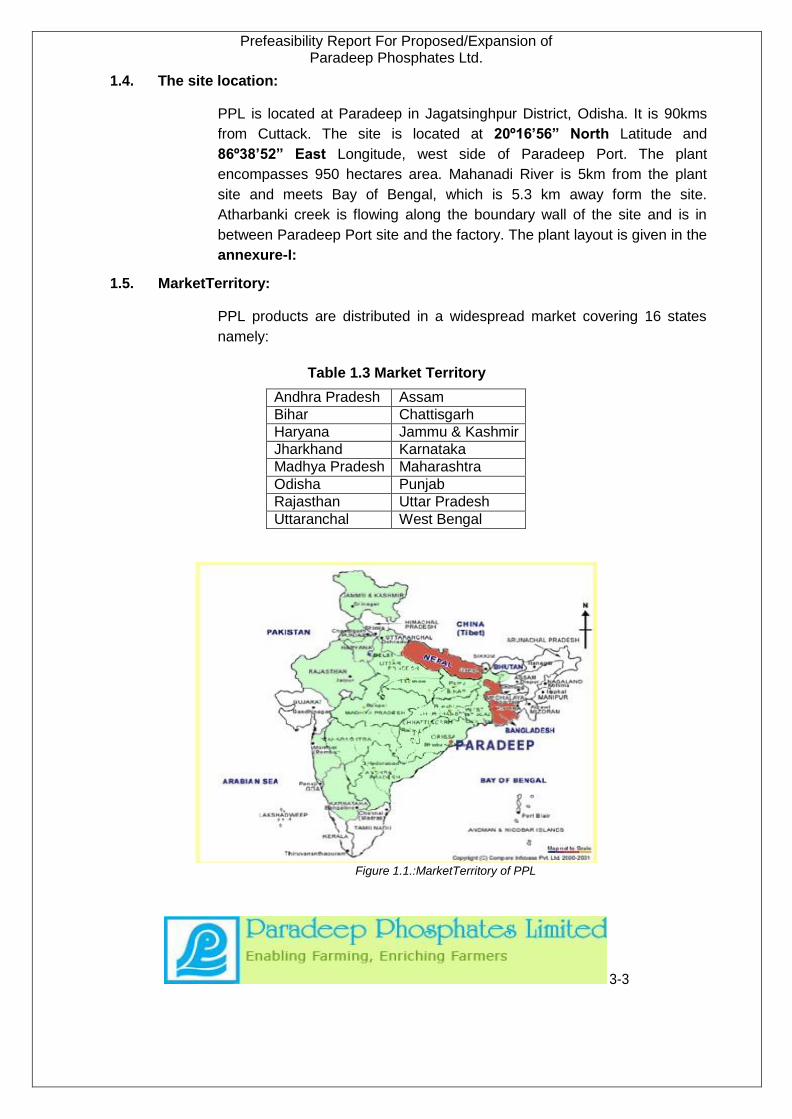
1.5. MarketTerritory:
PPL products are distributed in a widespread market covering 16 states
namely:
Table 1.3 Market Territory
Andhra Pradesh Assam
Bihar Chattisgarh
Haryana Jammu & Kashmir
Jharkhand Karnataka
Madhya Pradesh Maharashtra
Odisha Punjab
Rajasthan Uttar Pradesh
Uttaranchal West Bengal
Figure 1.1.:MarketTerritory of PPL
3-3
Prefeasibility Report For Proposed/Expansion of Paradeep Phosphates Ltd.
PPL also has a selling arrangement through its sister concerns viz. Zuari
Industries Ltd. (ZIL) to cater to markets in other parts of the country.
PPL's sales network comprises of private as well as institutional channels.
The strength of each channel varies from state to state. We have been able
to tap both channels successfully.
1.6. Need for the project:
Agriculture which accounts for one fifth of GDP provides sustenance to
two-thirds of our population. Besides, it provides crucial backward and
forward linkages to the rest of the economy. Successive five-year plan
have laid stress on self-sufficiency and self-reliance in food grains
production and concerted efforts in this direction. This is evident from the
fact that from a very modest level of 52 million MT in 1951-52, food grain
production rose to about 233.88 million MT in 2008-09.
By 2012, India’s population is likely to be around 1.2 billion and its
contribution to overall GDP and employment is likely to diminish
significantly. Producing food to satisfy the hunger and to provide
employment for buying food, remain the key concerns of agriculture.
1.6.1. Urea
Urea as a major source of nitrogen continued to dominate the scene of
nitrogenous Fertilisers consumption in the country. Urea at present is the
only controlled fertilizer and has a major share of consumption in the
country. All other Fertilisers put together are consumed in lesser quantity
than urea. Urea is covered under Essential Commodity Act (ECA) and the
Government issues movement orders under ECA to different
manufacturers. Under ECA, the Government also declares MRP of urea for
sale. Urea import and export is also highly restricted. Urea has recorded a
compound Annual Rate of Growth (CARG) in consumption of 3.6 percent
during the period of 1990-91 to 2009-10. Though the level of fertilizer
consumption in our country has all along been very low, the indigenous
production of urea has always been lagging much behind the consumption
requirement except in the year 2000-01.
3-4
Prefeasibility Report For Proposed/Expansion of Paradeep Phosphates Ltd.
The total estimated production of urea from the existing functional units will
be 210 lakh tonnes. Some of the existing units are in the process of
expanding their existing capacities by way debottlenecking. The projected
deficit level of about 70 lakh tonnes of urea by 2011-12 which would
increase to a level of 100 lakh tonnes by 2016-17. The Southern zones will
continue to be in deficit and only the western zone have sizeable surpluses
as at present though the surplus will lead to decline with time. On the basic
premise that any fertilizer manufacturing unit wil strive to market its product
as close to its production centre as possible in the interest of economizing
the transport cost burden, it can be assumed that the logical preference of
all units will be to market their production, as far as practicable, within the
irrespective 'home' states passing onto other states only for any surpluses.
Under this premise, PPL’s preferred marketing area will be the State of
Odisha. Odisha, however, cannot absorb the full production from the
proposed project of PPL. PPL, therefore, will have to move out of the state
to market the products. The most logical market to look for to sell the
surplus products will be the neighboring states of West Bengal, Jharkhand,
Chhattisgarh, eastern Uttar Pradesh, and Madhya Pradesh. The proposed
marketing area is highly deficit in the supply of urea
1.6.2. Di-ammonium Phosphate (DAP)
Paradeep Phosphates Ltd. (PPL) has proposal for capacity expansion of
existing DAP plants by 0.4 Million tonnes per annum which is situated at
the port town of Paradeep.
1.6.3. Phosphatic Fertilizer Products:
The most common of the phosphatic fertilizers presently used in India for
application to improve soil fertility are:
Single Super Phosphate (SSP)
Triple Super Phosphate (TSP)
Di-ammonium Phosphate (DAP)
Nitro-Phosphates-Potash Complexes (NPK)
3-5

Prefeasibility Report For Proposed/Expansion of Paradeep Phosphates Ltd.
Nitro-phosphates (NP)
Urea Ammonium Phosphate (UAP)
Of these, only SSP and TSP are exclusive P2O5 carriers. All other
products contain N and P2O5 (and some also K2O) in various proportions.
However, they are basically used for the purpose of applying P2O5 (and
K2O) to the soil. When such compounds are used, the doses of nitrogen
fertilizers is adjusted, after taking into account the nitrogen content in the
compound fertilizers. Any additional requirement of N is commonly applied
as top or side dressing.
Based on solubility, phosphatic fertilizers are graded as water soluble,
citrate soluble and insoluble phosphates. Water soluble phosphatic
fertilizers are generally found superior to other forms of fertilizers excepting
acid soils.
At present, DAP (18:46: 0) is the most widely used phosphatic fertilizer
product in India, accounting for two third of the total apparent consumption
of P in 2009-10. It is considered suitable for a wide variety of crops
including those which need high dose of P2O5 and low dose of N,
particularly at the time of sowing, such as pulses and other leguminous
crops. Studies have also shown that DAP does not affect the seeds even
when applied under relatively dry farming conditions, unlike straight and
some other complex fertilizers. Crops such as oilseeds and pulses are
generally sown under such conditions. It has also been favoured as basal
dressing for most crops. Another favourable factor with DAP is that nearly
the entire P2O5 is available to the plants immediately. DAP is also
compatible with all other fertilizers so that other straight nitrogenous
fertilizers as well as potassium can be added to it according to
requirements, without side reactions or handling problems. Since, both
Urea and DAP have similar sized granules, mixing them is particularly
easy. Thus, it provides scope for correct nutrient input adjustments,
including provision for top dressing. As a high analysis fertilizer, the
incidence of transport cost per unit of nutrient in DAP is the lowest of all
phosphatic fertilizers produced in India.
The projections made by FAI in respect of DAP is like by 2016-17 demand
would be 12413 thousand tonnes which would rise to 14036 thousand
tonnes in 2024-25.
The total demand of P2O5 is expected to increase from 8426 thousand
tonnes in 2012-13 to 9600 in 2016-17 and to 11530 thousand tonnes in
2024-25
Total supply of P2O5 is expected to
increaseatanannualgrowthrateofabout5%from4374thousandtonnesduring
2009-10 to 6155 thousand tonnes during2016-17
3-6
Prefeasibility Report For Proposed/Expansion of Paradeep Phosphates Ltd.
On the basic premise that any fertilizer manufacturing unit will strive to
market its product as close to its production centre as possible in the
interest of economizing the transport cost burden, it can be assumed that
the logical preference of all units will be to market their production, as far
as practicable, within their respective 'home' states passing on to other
states only for any surpluses. Under this premise, PPL’s preferred
marketing area will be the State of Odisha. Odisha, however, cannot
absorb the full production from the proposed project of PPL. PPL,
therefore, will have to move out of the state to market the products. The
most logical market to look for to sell the surplus products will be the
neighboring states of West Bengal, Jharkhand, Chattisgarh, eastern Uttar
Pradesh, and Madhya Pradesh. The proposed marketing area is highly
deficit in the supply of phosphatic fertilizers.
1.6.4. Granular Single Super Phosphate
Single Super phosphate is a chemical Fertilizer which contains Phosphorus
as a major plant nutrient. It is relatively very cheap and contains many
micro nutrients like Calcium, Magnesium, Iron, Aluminium, Sulphur.
It is a poor man’s fertilizer which also treats Sulphur deficiency of fertilizers
and results in enhancement of yields at the least cost. SSP is an essential
fertilizer. Further growth of agriculture would be possible with balanced use
of fertilizer by increasing the share of SSP consumption in comparison to
Urea, DAP and NPK fertilizers.
Single Super Phosphate (SSP) fertilizer industry is the pioneering fertilizer
industry in the country. SSP is a poor farmer’s fertilizer. (price wise) is an
option to optimize the use of phosphatic fertilizers. It also helps to treat the
sulphur deficiency of soils (40% Indian soil are sulphur deficient) as well as
for further enhancement of yields at the least cost. In various crops, which
requires more of sulphur and phosphate like oilseeds pulses sugarcane
fruits and vegetables tea etc. SSP is an essential fertilizer. Further growth
of agriculture would be possible with balanced use of fertilizer by increasing
the share of SSP consumption in comparison to Urea, DAP and NPK
fertilizers. Following trends further reinforces this fact.
As per the Nutrient Based Subsidy (NBS), the Government is offering a
Fixed per Kg subsidy for application on N, P, K & S as well as
micronutrients. The NBS has brought the price parity to the farmers for
P&K fertilizers based on nutrient content. The NBS was announced in
March, 2010 for 2010-11 and revised again in March, 2011 for FY 2011-12.
In view of high deficit in the supply of urea (nitrogenous) and other
(phosphate and potash) fertilizers in the country at present and likely to
further increase substantially in future PPL has decided to initiate its
activities for manufacturing urea, DAP, SSP fertilizer and some other
important chemicals in the deficit state of Odisha.
3-7
Prefeasibility Report For Proposed/Expansion of Paradeep Phosphates Ltd.
1.6.5. Ammonium Nitrate
Besides being used as a fertilizer, ammonium nitrate is the cheapest
source of chemical energy available today and a vital part of every
construction project. It’s an indispensable element used in making
explosives, which are further used in blasting/ mining of ore, coal,
limestone, bauxite, copper etc. The infrastructure boom augurs well for
growth of this division. The demand has been growing at a CAGR of 8%
and is expected to continue for sometime more. International Prices have
risen sharply and reports indicate demand for industrial grade ammonium
nitrate to remain firm with major thrust on mining & infrastructure activities
in Odisha, Bihar, Jharkand & Chattisgarh. The total demand for ammonium
nitrate is projected as follows:
The requirement of ammonium nitrate for explosive industry has been
worked out as 844 thousand tonnes in 2014-15 and 985 thousand tonnes
in 2016-17.
As mentioned earlier in the report, ammonium nitrate is required, in
relatively small quantities, for manufacture of nitrous oxide- a medical
gaseous anesthetic, dyes & dyestuffs and textile auxiliaries. In so far as
nitrous oxide is concerned, ammonium nitrate is a critical input and so is its
quality. The requirement of ammonium nitrate for dyes & dyestuffs as well
as auxiliaries may increase progressively to about 1060 tonnes by the year
2016-17
At present, demand for ammonium nitrate exceeds its supply. The
shortfalls are being met through imports.
A new 3,00,000 tonnes ammonium nitrate plant of Deepak Fertilisers and
Petrochemicals Corporation Ltd. (DFPCL) at Paradeep (Odisha) is under
planning stage but stuck somewhere half way. If this DFPCL eastern region
plant is commissioned and at 100% capacity utilisation, the total supply of
ammonium nitrate in the country by the year 2014-15 will increase to a
level of around 560,000 tonnes. This will leave a gap ofaround 4.50 lakh
tonnes by the year 2014-15 which would increase to around 7 lakh tonnes
by the year 2016-17.Almost 65 per cent of the projected capacity of
explosives in the country is in the states of Madhya Pradesh Chhattisgarh
and Jharkhand. Hence, a new unit for production of Ammonium Nitrate in
Odisha by PPL can be considered as a forward step in development of the
region in particular and the country in general.
1.6.6. Nitric AcId
Nitric acid, chemical formula, HNO3,is oneof the basic„building blocks‟ of
the chemical industry. Nitric Acid is sold in different concentration. The
major amongs these are 53 per cent, 60 per cent and 98 per centgrades.
3-8
Prefeasibility Report For Proposed/Expansion of Paradeep Phosphates Ltd.
Besides these, many dealers and manufacturers of chemicals are
concentratingNitricAcidto70to75per cent grade and this grade is used in
bullion refining mostly.
1.6.6.1. Weak Nitric Acid:
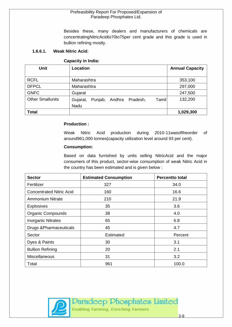
Capacity in India:
Unit Location Annual Capacity
RCFL Maharashtra 353,100
DFPCL Maharashtra 297,000
GNFC Gujarat 247,500
Other Smallunits Gujarat, Punjab, Andhra Pradesh, Tamil
Nadu
132,200
Total 1,029,300
Production :
Weak Nitric Acid production during 2010-11wasoftheorder of
around961,000 tonnes(capacity utilization level around 93 per cent).
Consumption:
Based on data furnished by units selling NitricAcid and the major
consumers of this product, sector-wise consumption of weak Nitric Acid in
the country has been estimated and is given below :
Sector Estimated Consumption Percentto total
Fertilizer 327 34.0
Concentrated Nitric Acid 160 16.6
Ammonium Nitrate 210 21.9
Explosives 35 3.6
Organic Compounds 38 4.0
Inorganic Nitrates 65 6.8
Drugs &Pharmaceuticals 45 4.7
Sector Estimated Percent
Dyes & Paints 30 3.1
Bullion Refining 20 2.1
Miscellaneous 31 3.2
Total 961 100.0
3-9
Prefeasibility Report For Proposed/Expansion of Paradeep Phosphates Ltd.
Demand:
The demand projection for weak Nitric Acid in the country for the years
2008-09, 2011-12, & 2014-15 are 1324000, 1389000 & 1464000 tonnes
respectively.
Against the demand of13.89 lakh tonnes of weak Nitric Acid by 2011-
12,DFPCL is coming up with a new capacity (300,000 tonnes) in the
eastern region for captive consumption for its ammonium nitrate
production. Thus, the total production likely to be available would be
around12lakh tonnes 90 percent of capacity utilization level. This will
leavea gap of around120,000 tonnes by 2008-09 which would increase to a
level of around 1.90 lakh tonnes in 2011-12 and 2.64 lakh tonnes by 2014-
15 for which an additional capacity of weak Nitric Acid would be required in
the country
1.6.6.2. Strong Nitric Acid:
Capacity:
At present there are six plants which are manufacturing Concentrated Nitric
Acid (CNA), three of which are Captive- IEL Gomia manufacturing
nitroglycerin and nitrocellulose, DGOF Bhandara which is manufacturing
TNT and catering to the needs of the defence and third plant is of
Hindustan Organic Chemicals Ltd Rasayani, which manufacture nitro
benzene, para-nitro chlorobenzene, orthonitro chloro benzene, nitro
toluene and di-nitro benzene.
The acid produced by all these plants is of 98per cent strength which is
termedus fuming Nitric Acid.The three plants, namely RCF, GNFC and
Deepak Fertilizers
& Petrochemicals Ltd. (DFPCL) are for merchan sale. The combined
capacity of these units at present is of the order of 162,000 tonnes per
annum
Consumption:
Present estimated consumption is around 162600 tonnes in India, where
aromatic compound producing companies consume the maximum of it
(65.6%)
Demand:
The demand projections for weak Nitric Acid in the country for the years
2008-09, 2011-12 and 2014-15 are 1324000, 1389000 & 1464000 tonnes
respectively, Against the demand of 13.89 lakh tonnes of weak Nitric Acid
by 2011-12,DFPCL is coming up with a new capacity (300,000tonnes) in
the eastern region for captive consumption for its ammonium nitrate
production. Thus, the total production likely to be available would be
around12 lakh tonnes 90percent of capacity utilization level. This will leave
3-10
Prefeasibility Report For Proposed/Expansion of Paradeep Phosphates Ltd.
a gap of around120,000 tonnes by 2008-09 which would increase to a level
of around 1.90 lakh tonnes in 2011-12 and 2.64 lakh tonnes by 2014-15 for
which an additional capacity of weak Nitric Acid would be required in the
country.
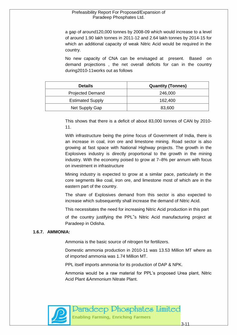
No new capacity of CNA can be envisaged at present. Based on
demand projections , the net overall deficits for can in the country
during2010-11works out as follows
Details Quantity (Tonnes)
Projected Demand 246,000
Estimated Supply 162,400
Net Supply Gap 83,600
This shows that there is a deficit of about 83,000 tonnes of CAN by 2010-
11.
With infrastructure being the prime focus of Government of India, there is
an increase in coal, iron ore and limestone mining. Road sector is also
growing at fast space with National Highway projects. The growth in the
Explosives industry is directly proportional to the growth in the mining
industry. With the economy poised to grow at 7–8% per annum with focus
on investment in infrastructure
Mining industry is expected to grow at a similar pace, particularly in the
core segments like coal, iron ore, and limestone most of which are in the
eastern part of the country.
The share of Explosives demand from this sector is also expected to
increase which subsequently shall increase the demand of Nitric Acid.
This necessitates the need for increasing Nitric Acid production in this part
of the country justifying the PPL‟s Nitric Acid manufacturing project at
Paradeep in Odisha.
1.6.7. AMMONIA:
Ammonia is the basic source of nitrogen for fertilizers.
Domestic ammonia production in 2010-11 was 13.53 Million MT where as
of imported ammonia was 1.74 Million MT.
PPL itself imports ammonia for its production of DAP & NPK.
Ammonia would be a raw material for PPL’s proposed Urea plant, Nitric
Acid Plant &Ammonium Nitrate Plant.
3-11

Prefeasibility Report For Proposed/Expansion of Paradeep Phosphates Ltd.
So PPL intends to have an indigenous production of ammonia for its DAP
&Urea & rest successive plants and help India being self sufficient in
production of ammonia and lower import of ammonia.
1.6.8. Aluminium Flouride
Aluminium Fluoride (AlF3) is an inorganic compound used primarily in the
production of aluminium. This colourless solid can be prepared
synthetically but also occurs in nature. In Odisha, Nalco, Vedanta, Indal,
Hindalco & Utkal Aluminium are the five prime consumers of Aluminium
Fluoride who use it as a flux in their smelter.
Nalco’s annual consumption is around 11000 MT
Vedanta has its 2 plants operating, 2 streams in Odisha & 1 in
Chhattisgarh. It has intended to expand its streams with 2 more streams in
Odisha and 1 more in Chhattisgarh.
Vedanta’s annual consumption of Aluminium Fluoride is around 19,800 MT
which is proposed to increase to 39,600 MTPA during 2013-14,
Indale is also a huge consumer of Aluminium Fluoride.
Looking forward to this consumption scenario of Aluminium Fluoride in
Odisha itself, PPL would like to convert the fluorine recovered from its
phosphoric acid, dehydrate process to a high quality aluminium fluoride
(high bulk density aluminium fluoride) instead of having to dispose it by the
way of neutralization and add Aluminium Fluoride to its product portfolio.
Fluorine abatement measures are to be taken care of before installing
Aluminium Fluoride Plant.
3-12
Prefeasibility Report For Proposed/Expansion of Paradeep Phosphates Ltd.
2. PROJECT DESCRIPTION (EXISTING SYSTEM)
2.1. Plant Production scenario:
In the proposed expansion project Paradeep Phosphates Limited (PPL)
intends to add some new products and also expands the capacities of
existing products as given below:
i. Urea (New product) ii. GSSP (New product) iii. DAP (Expansion) iv. Ammonia (Intermediate Product) v. Ammonium nitrate (New product) vi. Weak Nitric Acid (Intermediate Product), Conc. Nitric Acid (New Product) vii. Aluminium Fluoride (New product)
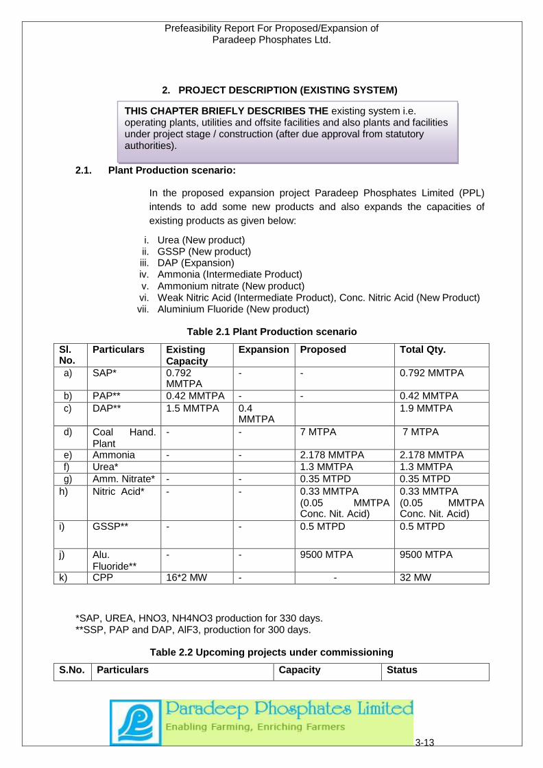
Table 2.1 Plant Production scenario
Sl. No.
Particulars Existing Capacity
Expansion Proposed Total Qty.
a) SAP* 0.792 MMTPA
- - 0.792 MMTPA
b) PAP** 0.42 MMTPA - - 0.42 MMTPA
c) DAP** 1.5 MMTPA 0.4 MMTPA
1.9 MMTPA
d) Coal Hand. Plant
- - 7 MTPA 7 MTPA
e) Ammonia - - 2.178 MMTPA 2.178 MMTPA
f) Urea* 1.3 MMTPA 1.3 MMTPA
g) Amm. Nitrate* - - 0.35 MTPD 0.35 MTPD
h) Nitric Acid* - - 0.33 MMTPA (0.05 MMTPA Conc. Nit. Acid)
0.33 MMTPA (0.05 MMTPA Conc. Nit. Acid)
i) GSSP** - - 0.5 MTPD 0.5 MTPD
j) Alu. Fluoride**
- - 9500 MTPA 9500 MTPA
k) CPP 16*2 MW - - 32 MW
*SAP, UREA, HNO3, NH4NO3 production for 330 days. **SSP, PAP and DAP, AlF3, production for 300 days.
Table 2.2 Upcoming projects under commissioning
S.No. Particulars Capacity Status
3-13
THIS CHAPTER BRIEFLY DESCRIBES THE existing system i.e. operating plants, utilities and offsite facilities and also plants and facilities under project stage / construction (after due approval from statutory authorities).
Prefeasibility Report For Proposed/Expansion of Paradeep Phosphates Ltd.
1. Gypsum pond 70-80 hectare area Under Commissioning
2.2. Existing Operating Plant and System:
2.2.1. Introduction:
Paradeep Phosphates Limited (PPL) is operating a large Fertilizer
complex in Paradeep, Odisha, India where PPL manufacture various
grades of NPK fertilizer. PPL is a prime player in the Phosphatic
fertilizers which have applications in a wide range of crops. The fertilizer
complex consists of following manufacturing units.
• 4400MTPD of Sulphuric Acid Plant(3 stream)
• 1400 MTPD of Phosphoric Acid Plant
• 5000 MTPD of Di Ammonium Phosphate Plant/NPK Plant (4 trains)
• 2X16 MW + 1X23 MW Captive Power Plant
• 240 TPD of Zypmite Plant
The fertilizer complex is using imported sulphur& rock phosphates to
produce sulphuric acid and phosphoric acid, along with imported MOP for
NPK complex production. Since captive production of phosphoric acid
cannot cater to the four streams of DAP plant, part of the phosphoric acid
requirement is made through imports. The entire ammonia requirement is
met through imports.
The other facilities available are as follows:
Rock Silo
Sulphur Silo
MOP Silo
Sulphuric Acid Storage
Phosphoric Acid Storage
Ammonia Storage
Di-Ammonium Phosphate Storage & Bagging
Marine Jetty
ETP & STP
❖ Other Auxiliary systems include:
a) HSD/LFO/HFO storage b) Fuel Oil Storage c) LPG Cylinder Storage d) Captive Power Plant
3-14

Prefeasibility Report For Proposed/Expansion of Paradeep Phosphates Ltd.
2.3. Land distribution in Existing Plant:
The details of land use on core area in PPL premises are
Table 2.3 Land distribution in Existing Plant
S.No. Land-Use Area covered
1) Plant & Building 35.00acres,
2) Waste Treatment & Handling facilities 196.00 acres,
3) Raw water Reservoir 230.00 acres
4) Water Treatment Plant 4.40 acres
5) Plantation 854.00 acres (GREEN BELT- 37%).
6) Road 63.00 acres
7) Colony 300.00 acres
Total 1682.4
8) Open area and Water bodies* 600.00acres.
Total 2282.4 acres
*The proposed Projects will require 534 acre land. Paradeep already have sufficient Land The detail requirement of land for Proposed Plants are given in Table 3.1
2.4. Process Description
2.4.1. Sulphuric Acid Plant.
Sulphuric Acid (SA) plant is based on the most modern double conversion
double absorption process of M/s Lurgi GMBH, West Germany (DCDA
process). It is laid in two streams, each of 1200 MTPD capacity. The raw
material, elemental sulphur is transported by means of belt conveyor to the
sulphur bin. Sulphur is melted in a melting pit by means of heating coils,
heating media being steam. The molten sulphur is stored in a liquid sulphur
storage tank after passing through filters. The molten sulphur is fed to the
sulphur furnace where complete combustion takes place which gives rise
to a SO2 concentration of about 11.5%. The heat of combustion is
removed by a waste heat boiler where steam (approximately 60
MT/hr) is produced.
The furnace gas cooled to a temperature of 420ºC- 430º C is fed to a
converter having 4 catalyst beds. SO2 to SO3 conversion takes place in
first three beds and first absorption of SO3 gases takes place in
intermediate absorber. Remaining SO2 gases from Intermediate
absorber is passes through the fourth bed for optimum conversion of
remaining SO2 to SO3. SO3 gas from fourth bed is cooled to a
3-15
Prefeasibility Report For Proposed/Expansion of Paradeep Phosphates Ltd.
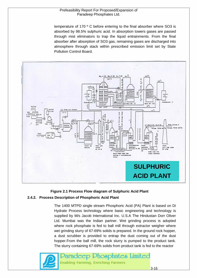
temperature of 170 º C before entering to the final absorber where SO3 is
absorbed by 98.5% sulphuric acid. In absorption towers gases are passed
through mist eliminators to trap the liquid entrainments. From the final
absorber after absorption of SO3 gas, remaining gases are discharged into
atmosphere through stack within prescribed emission limit set by State
Pollution Control Board.
Figure 2.1 Process Flow diagram of Sulphuric Acid Plant
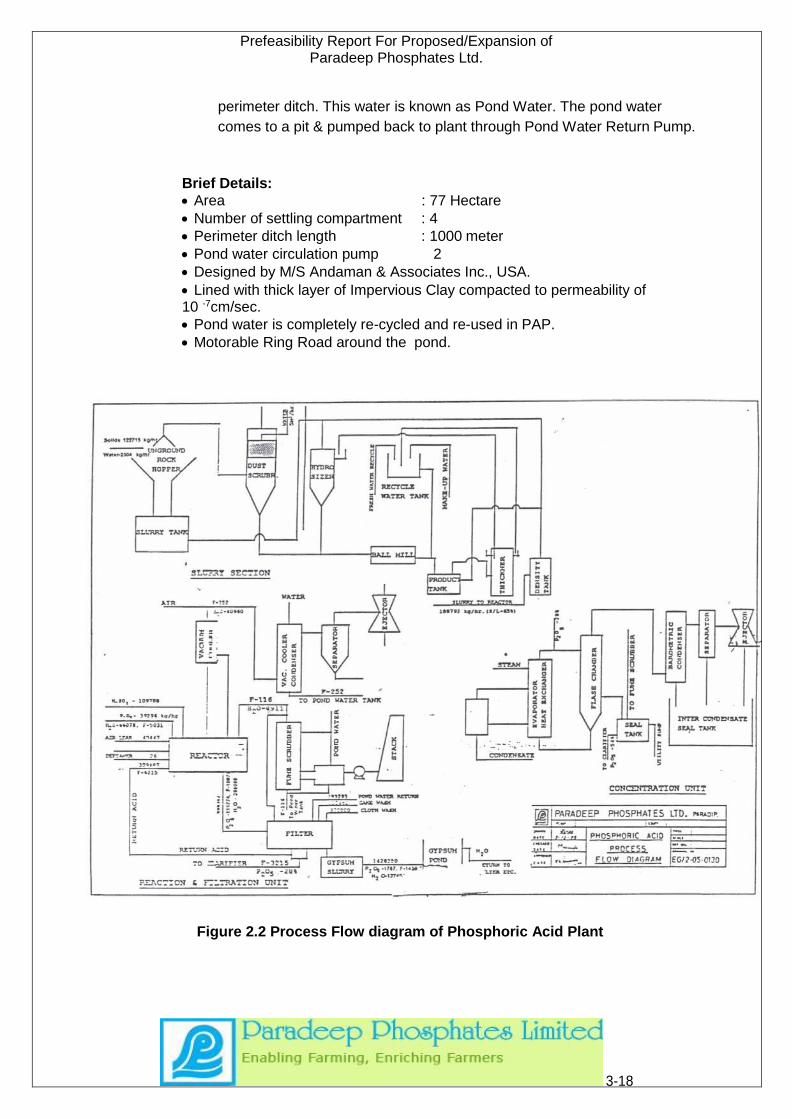
2.4.2. Process Description of Phosphoric Acid Plant
The 1400 MTPD single stream Phosphoric Acid (PA) Plant is based on Di
Hydrate Process technology where basic engineering and technology is
supplied by M/s Jacob International Inc. U.S.A The Hindustan Dorr Oliver
Ltd. Mumbai was the Indian partner. Wet grinding process is adopted
where rock phosphate is fed to ball mill through extractor weigher where
wet grinding slurry of 67-69% solids is prepared. In the ground rock hopper,
a dust scrubber is provided to entrap the dust coming out of the dust
hopper.From the ball mill, the rock slurry is pumped to the product tank.
The slurry containing 67-69% solids from product tank is fed to the reactor
3-16
SULPHURIC
ACID PLANT

Prefeasibility Report For Proposed/Expansion of Paradeep Phosphates Ltd.
at first and third agitator point. Concentrated sulphuric acid having 98.4%
concentration and recycle phosphoric acid are fed to the reactor. The
reaction slurry proceeds through reaction section and underflows into the
vacuum cooler feed compartment where degassing takes place and the
slurry is then pumped to the vacuum cooler. Defoamer is added to the
reactor to inhibit the formation of foam/froth.
The slurry is cooled down in the vacuum cooler by maintaining a vacuum of
150-300mm Hg absolute by evaporation of water. A barometric condenser
and vacuum jet system remove the vapours. The slurry from the vacuum
cooler flows down the reactor to filter feed tank through a vertical seal by a
vacuum cooler tank. Filter feed is distributed on a horizontal filter through
feed box, where phosphoric acid is separated from gypsum. The cake in
the filter is given four successive washes by a filtrate of 12% P2O5, heated
pond water and a final wash. The de- watered cake after fourth wash is
removed, slurried and pumped to the gypsum pond. Air that passes
through the cake is disengaged from the filtrates in the filtrate recovery
system and passes through the filter condenser where gas is cooled and
vapours condensed. The pond water used in the filter condenser
discharges through the pond water tank.
The scrubbing system provides a preliminary pond water quench to cool
the vent gases. The gases are then scrubbed in the first stage in a cross
flow packed bed scrubber using cold pond water. The gases then pass
through a second packed bed, which reduces the emission below 0.0058
kg flourine per tonne of acid. A mist eliminator eliminates droplet
entrainment. Acid from filter is pumped to a clarifier. The clarifier overflow
goes either to a product acid tank or to the evaporator as required. The
sludge from the clarifier is either recycled to the clarifier or to the reactor or
transferred to the DAP plant. Concentration of the acid, whenever
necessary is carried out in the evaporators. The concentrated acid
overflows from the flash chamber through a barometric condenser. The
non-condensable are removed by a vacuum jet system in condenser
operating for the cooling water system.
The byproduct Gypsum, as Gypsum slurry is discharged from the Gypsum
Slurry pump of Phosphoric Acid Plant to Gypsum Pond through HDPE
pipeline.
The Gypsum Pond consists mainly of four settling compartments &
Perimeter surge ditch. The perimeter ditch is bound by perimeter dike. The
total area of Gypsum pond is 77 hectare. Normally one settling
compartment is taken on line & the other are kept as stand by. The
Gypsum Slurry at about 11-15% solid is discharged to one settling
compartment. It has to travel a horizontal length of approximately 1000m
by which the solids get settled in the settling pond & water is decanted to
3-17
Prefeasibility Report For Proposed/Expansion of Paradeep Phosphates Ltd.
perimeter ditch. This water is known as Pond Water. The pond water
comes to a pit & pumped back to plant through Pond Water Return Pump.
Brief Details:
• Area : 77 Hectare
• Number of settling compartment : 4
• Perimeter ditch length : 1000 meter
• Pond water circulation pump 2
• Designed by M/S Andaman & Associates Inc., USA.
• Lined with thick layer of Impervious Clay compacted to permeability of 10 -7cm/sec.
• Pond water is completely re-cycled and re-used in PAP.
• Motorable Ring Road around the pond.
Figure 2.2 Process Flow diagram of Phosphoric Acid Plant
3-18
Prefeasibility Report For Proposed/Expansion of Paradeep Phosphates Ltd.
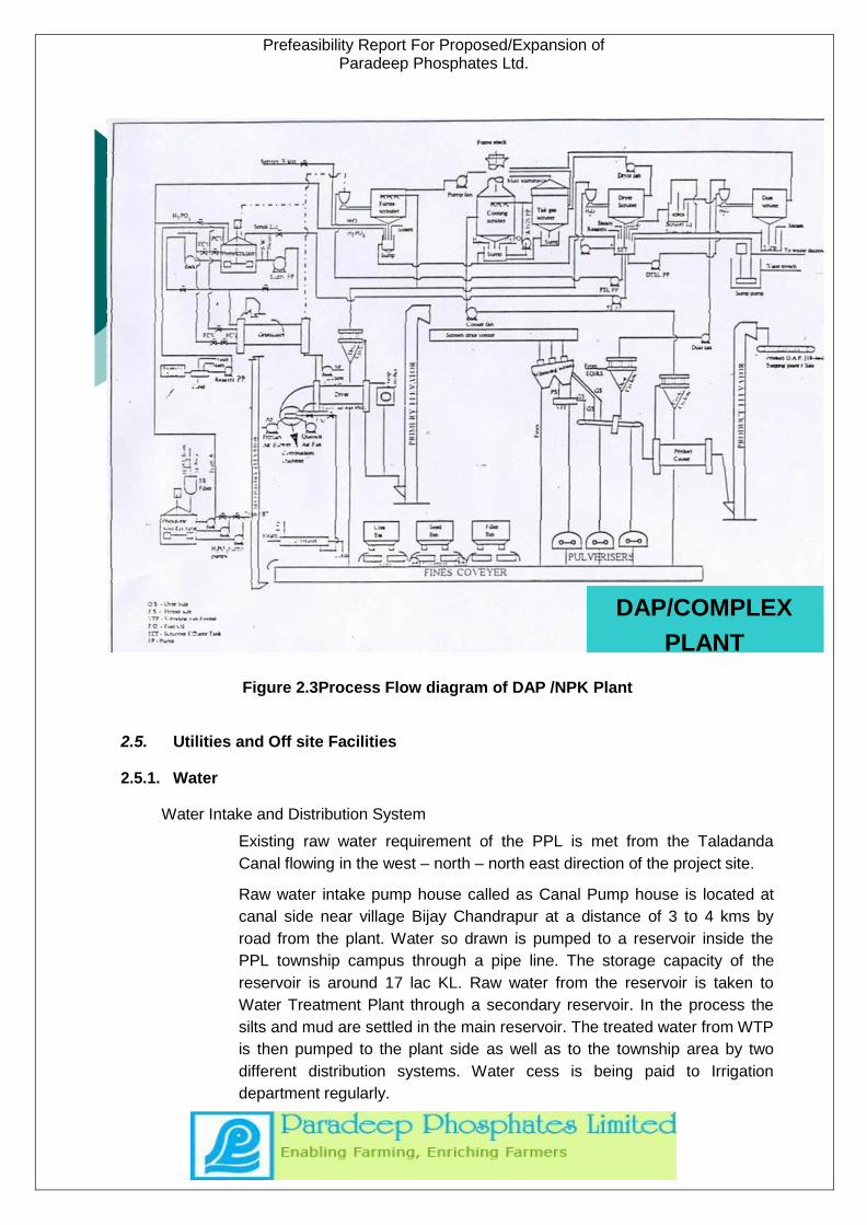
2.4.3. Process Description of Di-Ammonium Phosphate/NPK Plant (DAP/NPK):
DAP/ NPK plant is based on Dorocco Granulation Process consisting of
four identical streams and has capacity to produce 5000 MT per day. The
main raw materials are phosphoric acid, ammonia, sand (as filler) and
Defoamer Phosphoric acid(54%)and an hydrous ammonia are pumped
from storage tanks to pre- neutralizers (PN Reactor) reaction takes place
as a result of which DAP and mono- ammonium phosphates are formed.
The slurry contains 80% solids and is pumped to rotary granulators where
further ammonia is fed to convert mono-ammonium phosphate to di-
ammonium phosphate in a mole ratio of 1.8.
The recycle material along with the filler mixed in the fines conveyors are
fed to the granulators. Wet DAP granules flow by gravity to rotary dryers
where they are dried in aco- current stream of hot air. The dried granules
are screened for size separation in doubled eck vibrating screens where
over sized and under sized material are sent back to the system by means
of fine conveyors. The product falls into the product compartment of the
screen hopper and is withdrawn through product coolers and dispatched to
product storage (50000MTcapacity) or direct to the Bagging Plant as
required.
The wet process system consists of scrubbing and reaction sections.
Scrubbers, which are venture cyclone type, handle the ammonia and dust
bearing fumes and gases evolved from the pre-neutralizer, granulator, drier
and dust systems. The scrubbing medium for the three scrubbers is re-
circulated phosphoric acid solution. The fumes and gases from dryer and
fume scrubbers are forced by respective fans to a tail gas scrubber where
as gases and fumes from pre neutralizer granulators and coolers are
scrubbed na exhausted to atmosphere through the fume stack.
Prefeasibility Report For Proposed/Expansion of Paradeep Phosphates Ltd.
Figure 2.3Process Flow diagram of DAP /NPK Plant
2.5. Utilities and Off site Facilities
2.5.1. Water
Water Intake and Distribution System
Existing raw water requirement of the PPL is met from the Taladanda
Canal flowing in the west – north – north east direction of the project site.
Raw water intake pump house called as Canal Pump house is located at
canal side near village Bijay Chandrapur at a distance of 3 to 4 kms by
road from the plant. Water so drawn is pumped to a reservoir inside the
PPL township campus through a pipe line. The storage capacity of the
reservoir is around 17 lac KL. Raw water from the reservoir is taken to
Water Treatment Plant through a secondary reservoir. In the process the
silts and mud are settled in the main reservoir. The treated water from WTP
is then pumped to the plant side as well as to the township area by two
different distribution systems. Water cess is being paid to Irrigation
department regularly.
DAP/COMPLEX
PLANT
Prefeasibility Report For Proposed/Expansion of Paradeep Phosphates Ltd.
Two process water tanks are installed to cater to the needs of process
water from the plant as well as supply of firewater. In the process water
pump-bay a jockey pump is installed to keep fire hydrant pressure. There
are one diesel driven and two motor driven fire water pumps. Pumps are
kept connected so that they could be started immediately whenever
necessary. Firewater inlet to the pumps is at a lower level than the process
water intake. Process water clarifier is provided which takes water from a
huge water reservoir, before pumping.
Permitted withdrawal of water from the Taladanda Canal is 5,000,000
Gallons per Day. (22730 m3/day)
As per notice on demand dated 16/10/2012, water withdrawn was 16949
m3/day quite lower than the permission level.
New SAP, CPP & DM Plant would require an extra volume of
approximately 7260 m3/day.
Extra water required if any for the proposed upcoming plants will be
clarified & resolved and approvals and permissions would be taken for the
same.
2.5.2. Power &Distribution:
PPL has captive power generation facilities. Captive generation of power is
through co-generation from the waste steam of SAP. In addition there are
two Turbo Generators. These are extraction cum condensate type,
manufactured by BHEL, each having capacity of 16 MW. When one TG is
under operation, other works as spare and vice versa.
A new CPP is in project phase to assist the steam generation from New
sulphuric acid plant-2000 TPD. The capacity would be 23 MW and wll be
handling waste HP steam at 60 kg bar pressure & 480 0C.
The waste HP steam from SAP at 40 kg/cm2 pressure and 405 0C
temperature is used in Turbo Generator to produce power. In case of
shutdown of any stream of Sulphuric acid plant, the balance steam
requirement for generation of power is met through generation of steam
from oil fired boiler. The oil fired boiler has installed capacity of 110 TPH
steam at 40 kg/cm2 pressure and 4050C temperature. The boiler is of
BHEL make.
Total power requirement in the plant is 25.5 MW. Out of 25.5 MW captive
generation is 12 MW, while balance 13.5 MW is being drawn from state
electricity Grid.
In case of total power failure the backup HT power is supplied through 5
MVA DG set and LT power through two numbers of 1 KVA DG sets
2.5.3. Raw Material Handling
Prefeasibility Report For Proposed/Expansion of Paradeep Phosphates Ltd.
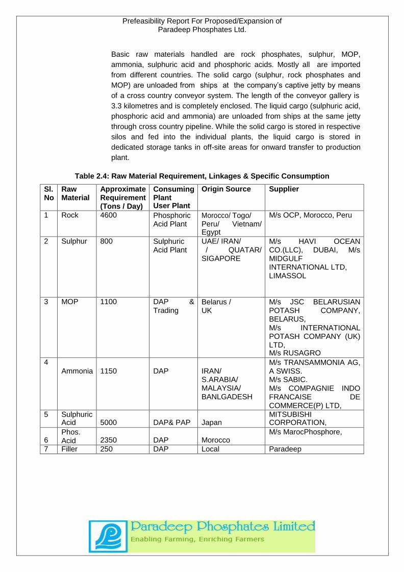
Basic raw materials handled are rock phosphates, sulphur, MOP,
ammonia, sulphuric acid and phosphoric acids. Mostly all are imported
from different countries. The solid cargo (sulphur, rock phosphates and
MOP) are unloaded from ships at the company’s captive jetty by means
of a cross country conveyor system. The length of the conveyor gallery is
3.3 kilometres and is completely enclosed. The liquid cargo (sulphuric acid,
phosphoric acid and ammonia) are unloaded from ships at the same jetty
through cross country pipeline. While the solid cargo is stored in respective
silos and fed into the individual plants, the liquid cargo is stored in
dedicated storage tanks in off-site areas for onward transfer to production
plant.
Table 2.4: Raw Material Requirement, Linkages & Specific Consumption
Sl. No
Raw Material
Approximate Requirement (Tons / Day)
Consuming Plant User Plant
Origin Source Supplier
1 Rock 4600 Phosphoric Acid Plant
Morocco/ Togo/ Peru/ Vietnam/ Egypt
M/s OCP, Morocco, Peru
2 Sulphur 800 Sulphuric Acid Plant
UAE/ IRAN/ / QUATAR/
SIGAPORE
M/s HAVI OCEAN CO.(LLC), DUBAI, M/s MIDGULF INTERNATIONAL LTD, LIMASSOL
3 MOP 1100 DAP &
Trading Belarus / UK
M/s JSC BELARUSIAN POTASH COMPANY, BELARUS, M/s INTERNATIONAL POTASH COMPANY (UK) LTD, M/s RUSAGRO
4
Ammonia
1150
DAP
IRAN/ S.ARABIA/ MALAYSIA/ BANLGADESH
M/s TRANSAMMONIA AG, A SWISS. M/s SABIC. M/s COMPAGNIE INDO FRANCAISE DE COMMERCE(P) LTD,
5 Sulphuric Acid
5000
DAP& PAP
Japan
MITSUBISHI CORPORATION,
6
Phos. Acid
2350
DAP
Morocco
M/s MarocPhosphore,
7 Filler 250 DAP Local Paradeep
Prefeasibility Report For Proposed/Expansion of Paradeep Phosphates Ltd.
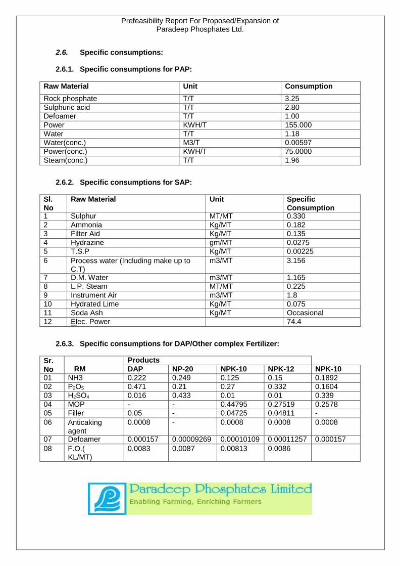
2.6. Specific consumptions:
2.6.1. Specific consumptions for PAP:
Raw Material Unit Consumption
Rock phosphate T/T 3.25
Sulphuric acid T/T 2.80
Defoamer T/T 1.00
Power KWH/T 155.000
Water T/T 1.18
Water(conc.) M3/T 0.00597
Power(conc.) KWH/T 75.0000
Steam(conc.) T/T 1.96
2.6.2. Specific consumptions for SAP:
Sl. No
Raw Material Unit Specific Consumption
1 Sulphur MT/MT 0.330
2 Ammonia Kg/MT 0.182
3 Filter Aid Kg/MT 0.135
4 Hydrazine gm/MT 0.0275
5 T.S.P Kg/MT 0.00225
6 Process water (Including make up to C.T)
m3/MT 3.156
7 D.M. Water m3/MT 1.165
8 L.P. Steam MT/MT 0.225
9 Instrument Air m3/MT 1.8
10 Hydrated Lime Kg/MT 0.075
11 Soda Ash Kg/MT Occasional
12 Elec. Power 74.4
2.6.3. Specific consumptions for DAP/Other complex Fertilizer:
Sr. No
RM
Products
DAP NP-20 NPK-10 NPK-12 NPK-10
01 NH3 0.222 0.249 0.125 0.15 0.1892
02 P2O5 0.471 0.21 0.27 0.332 0.1604
03 H2SO4 0.016 0.433 0.01 0.01 0.339
04 MOP - - 0.44795 0.27519 0.2578
05 Filler 0.05 - 0.04725 0.04811 -
06 Anticaking agent
0.0008 - 0.0008 0.0008 0.0008
07 Defoamer 0.000157 0.00009269 0.00010109 0.00011257 0.000157
08 F.O.( KL/MT)
0.0083 0.0087 0.00813 0.0086

Prefeasibility Report For Proposed/Expansion of Paradeep Phosphates Ltd.
2.6.4. Finished Product Handling
Bulk fertilizers are received in the bagging plant directly from the production
plant as well as from the product silo. This is then bagged, stitched and
loaded in wagons for dispatch. There are nine numbers of slats for carrying
out the activities and three numbers of platforms for loading the fertilizers in
the rakes. Controlling the weight variation of the bagged fertilizers is the
most important function of the bagging plant. It is a labor oriented
department. Around 600 persons are deployed in the bagging plant. The
average capacity of each slat is around 45 Ton per hour.
2.7. Bulk Storages
2.7.1. Ammonia Storage
Imported liquid ammonia is stored in 5 atmospheric storage tanks, each
having a capacity of 10,000 MT totalling to 50,000 MT. The tank is of 'Cup-
in-tank' type. These are double shelled tanks with double bottom and
double cylindrical shell with a single roof fabricated from low temperature
carbon steel. The space between the shells is connected with ammonia
vapour. Outer tank is insulated with polyurethane foam “foamed in-situ”
(100mmthick) and has aluminium sheet cladding. Insulation is secured with
stainless steel hoops to withstand wind velocity of 260-km/hr. Tank bottom
is insulated with foam glass and roof is insulated with fibre glass stacked to
a thickness of 250 mm on deck suspended from dome roof. The roof top is
painted with polyurethane paint. Ammonia is stored at atmospheric
pressure and temperature of-33ºC. Each tank has three safety valves at
different points for protection. These safety valves are connected to arelief
header and the header is connected to vent. Normal operating pressure of
the storage is 600mm water column (WC). There are two vents at a height
of 60.2metres and 70.15 meters. Three safety valves provided on each
tank are having following set pressures.
❖ 1stsafetyvalve: 950 mm WC
❖ 2ndsafetyvalve: 1000mmWC
❖ 3rdsafetyvalve: 1050 mm WC
Safety valves can be locked either in open or closed position. Without
inserting key, these cannot be opened or closed, once locked.
All the ammonia tanks are connected to a common refrigeration system.
2.7.2. Sulphuric Acid Storage Tank
There are four numbers of sulphuric acid storage tanks three of each
10,000 MT capacity and one of 5000MT capacity. A pump bay is situated
near the tanks and sulphuric acid from the storage tanks is pumped to the
Prefeasibility Report For Proposed/Expansion of Paradeep Phosphates Ltd.
day tank (2000 MT capacity) situated in Phosphoric Acid Plant premises
and to DAP plant for injection. Leakage from the pump and the overflow
from the storage tank are connected to sulphuric acid sump pit from where
acid is pumped back to No.1 tank. Over flow from the sump is neutralized
and discharged to the effluent drain, which leads to Effluent Treatment
Plant (ETP).
A 10000 MT capacity of Sulphuric acid tank is to be commissioned in near
future.
2.7.3. Phosphoric Acid Storage Tanks
For phosphoric acid solution, six numbers of mild steel rubber lined storage
tanks of each 10,000MT capacity is installed. Pumps situated near the
tank, pump phosphoric acid today tanks (2 numbers) situated in DAP plant.
Spillages, over flows and leakage are connected to a sump it where
phosphoric acid sludge accumulates. A sump pump installed in the pit
pumps over flow back to the storage tank.
Presently 2 nos. of Phosphoric acid tanks are in commissioning stage each
of holding capacity of 5000 cubic.m .One more tank is to be commissioned
in near future.
2.7.4. Heavy Fuel Oil/ LSHS Storage Tanks
There are two heavy fuel oil (FO) storage tanks each having a capacity of
1800 KL. Tanks are equipped with steam heating. All the tanks are
insulated with 50 mm thickness glass wool. Tanks are enclosed in a dyke
wall having a holding capacity of 2000 m3. Unloading facilities by trucks
exist. Leakage form tanks drain and overflow along with tank’s steam
heating condensate are collected through a drainage system inside
the dyke wall to control the spillage flow from pump bay and is directed
to the sump pit. For reclaiming oil from the pit, one submerged oil
reclaiming pump is provided which reclaims oil from the top of the pit and
discharges into storage tanks provided. Water collected in the pit goes to
the effluent drain pump and the fuel oil is pumped back to the storage tank.
One High Speed Diesel (HSD) oil day tank having a capacity of 15 KL is
located behind the emergency power house building of off-site storages.
2.7.5. Chlorine Storage
Chlorine is stored in tonners at Water Treatment Plant. The factory stores a
maximum of 2 tonners at a time. One tonner is equivalent to 930 kg. This
chlorine is in liquid form and is being used to treat the water. The empty
cylinders will be replaced by the filled ones on regular basis.
2.7.6. Muriate of Potash Storage
The muriate of potash is stored in a silo of capacity 35000 MT. Being
transported from jetty through the conveyors.
Prefeasibility Report For Proposed/Expansion of Paradeep Phosphates Ltd.
2.7.7. Rock Phosphate Storage
The rock phosphate is stored to the extent of 65000 MT. It is stored in an
enclosed shed called silo. Rock Phosphate is being transported from jetty
through the conveyors. The expansion of the silo has been done to
1,30,000 MT.
2.7.8. Sulphur Storage
The sulphur is stored in solid state to the extent of 45000 MT. It is stored in
an enclosed shed called silo. Sulphur is being transported from jetty
through the conveyors. The storage shed approximate dimensions are 194
m x 42 m x 10 m. The stored sulphur is transported through conveyors to
SAP.
2.7.9. LPG Storage
LPG cylinders are stored in a Godown. There are total 102 cylinders for
industrial use and 153 cylinders for domestic use. Godown has
approximate dimensions of 12 m x 8 m x 4 m.
2.8. Offsite Facilities
The important OFF Site facilities required for the smooth operation of the
plant are briefly given below.
2.8.1. Instrumentation
Automation and control system being an important feature, all parameters
are measured by instruments. PPL is able to regulate the production
process and improve the productivity.
DAP Plant, Phosphoric Acid plant, Captive Power Plant and Sulphuric Acid
Plant have adopted the Distributed Control System (DCS) whereby the
intricate details also are captured by the system.
2.8.2. Plant Lighting
The entire plant along with township is provided with adequate lighting
facilitated by energy efficient, high luminescent sodium vapor lamps and
high mast for widespread coverage.
2.8.3. Fire Fighting, Safety & Security
The fire fighting system is very important. The fire fighting personnel and
security guards are specially trained for all types of fire oriented
contingencies and also other safety emergencies in a simulated real-life
situation. The preventive measures for fire and Safety incidents and
accidents:
• Regular testing of fire pumps and fire tenders
• Regular inspection and upkeep of fire and safety equipment/vehicles
• Emergency preparedness and response /mock drills
Prefeasibility Report For Proposed/Expansion of Paradeep Phosphates Ltd.
• Creating awareness and formation of safety committees in all the plants
• Accident reporting, investigation and analysis
• Well-equipped with relevant infrastructure and manned round-the-clock
PPL has a battalion of 206 well trained and efficient security personnel
headed by Chief Security Officer. Security system and guards are
equipped with best safety appliances adequate enough to protect the plant
and personnel against any adverse situations.
The safety and security operations are carried out round the clock with
meticulous planning and vigorous implementation techniques, which take
into account the risk and hazards factors.
2.8.4. Electrical & Mechanical Maintenance
The company adorns a full-fledged electrical and mechanical workshop
within the plant premises with state – of – the – art machines and facilities
to cater to the day – to – day in-house maintenance jobs. Some of the
major breakdown jobs are done by employing certified and enlisted
contractors.
2.8.5. Environment
PPL is having a well-organized Environment department to take care of
various environmental issues of the industry, which includes but not limited
to compliance of statutory provisions of environment legislations.
Operation of Effluent Treatment Plant, regular monitoring of environmental
parameters and coordination with different departments in the plant for
effective environmental management are some of the activities. PPL is
having a well-equipped laboratory to carryout day – to – day analysis of
environmental parameters. PPL has installed a Weather Station to monitor
ambient temperature, wind speed, wind direction, rain fall and relative
humidity.
2.8.6. Man Power
Competent and qualified personnel are employed for various jobs. Direct
employment is around 1042. Out of this 602 are executives and 440 are
non-executives. Indirect employment is to the tune of 1120 deployed
through contractors. Temporary employment is around 39.
Summing up the figures, PPL has manpower of 2201 till 31stAug 2012.
PPL has provided housing facilities to all its personnel. Maintenance of the
colony is taken care by the civil department. The complex is having all
basic minimum amenities like shopping complex, school, play ground,
jogging trail, gymnasium, recreational club & hospital etc.
2.9. Environmental aspects
2.9.1. Air Emission:
Prefeasibility Report For Proposed/Expansion of Paradeep Phosphates Ltd.
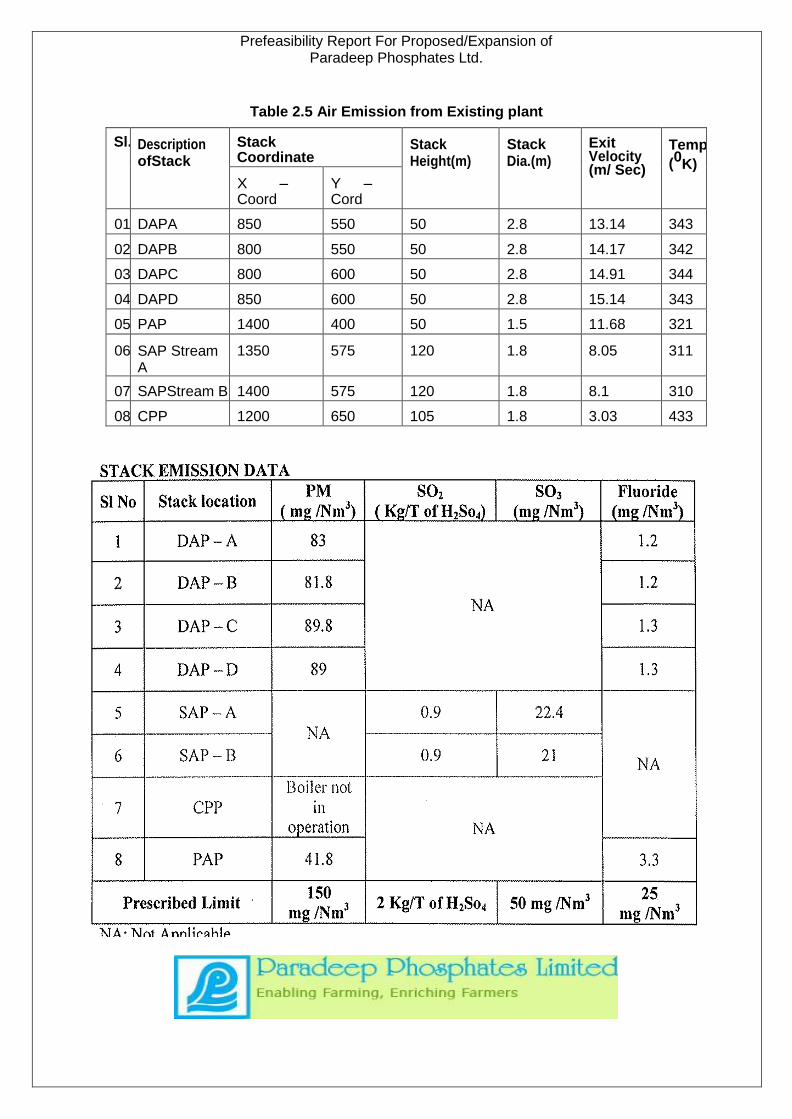
Table 2.5 Air Emission from Existing plant
Sl. Description ofStack
Stack Coordinate
Stack Height(m)
Stack Dia.(m)
Exit Velocity (m/ Sec)
Temp
(0K)
X – Coord
Y – Cord
01 DAPA 850 550 50 2.8 13.14 343
02 DAPB 800 550 50 2.8 14.17 342
03 DAPC 800 600 50 2.8 14.91 344
04 DAPD 850 600 50 2.8 15.14 343
05 PAP 1400 400 50 1.5 11.68 321
06 SAP Stream A
1350 575 120 1.8 8.05 311
07 SAPStream B 1400 575 120 1.8 8.1 310
08 CPP 1200 650 105 1.8 3.03 433
1800
ETP
Prefeasibility Report For Proposed/Expansion of Paradeep Phosphates Ltd.
2.9.2. Effluent:
The major sources of waste water generation from PPL are;
• Sulphuric Acid Plant
• Phosphoric Acid Plant
• DAP Plant
• Captive Power Plant
• Offsite and Bagging Plant
• Domestic Waste Water
Scrubbers, condensers of the vacuum evaporators, leakage from pumps,
spills, floor washings, cooling tower blow down, boiler blow down and wash
water mainly contribute to waste water stream from the above mentioned
units. It is apparent that a number of substances during the processing of
the product are discharged with the effluent that primarily includes
phosphates and fluorides.
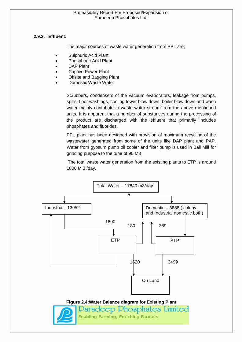
PPL plant has been designed with provision of maximum recycling of the
wastewater generated from some of the units like DAP plant and PAP.
Water from gypsum pump oil cooler and filter pump is used in Ball Mill for
grinding purpose to the tune of 90 M3
The total waste water generation from the existing plants to ETP is around
1800 M 3 /day.
1620 3499
Figure 2.4:Water Balance diagram for Existing Plant
Domestic – 3888 ( colony and Industrial domestic both)
180 389
Total Water – 17840 m3/day
Industrial - 13952
STP
On Land
30 | Page
Prefeasibility Report For Proposed/Expansion of Paradeep Phosphates Ltd.
2.9.2.1. Waste Water from Phosphoric Acid Plant
The major source of waste water from this unit is gypsum slurry. The by-product
gypsum is slurried with water and pumped to gypsum pond, where the fluoride
compounds form stable calcium fluoride and settle down. The plant has been
designed with a zero discharge concept. The supernatant from the gypsum pond,
which also accommodates the return water from various condensers, seal water,
plant washings and cooling tower blow down is recycled back into the system. The
phosphoric acid plant area is also paved to prevent ground percolation.
2.9.2.2. Waste Water Generation from SAP
There is as such no liquid effluent from the process area of sulphuric acid plant
except plant washings, blow down from cooling tower & boilers and condensate
from sulphur melting pit. During startup or upset condition of the plant the alkali
scrubber is put into operation and scrubbed liquor is taken to ETP for treatment
through a central effluent sump. The entire quantity is highly acidic. In case it finds
its way to percolate through soil then there are all possibilities of ground water
contamination. Thus steps are taken to pave the whole SAP area to prevent
ground percolation.
2.9.2.3. Waste Water from Di-Ammonium Phosphate Plant (DAP)
The plant is based on negative water balance and thereby no sources of liquid
effluent are anticipated except for the occasional washing and spillage. Such
discharges are intermittent in nature and in small quantities. Zero discharge
is attained through complete recycle of the scrubber water back into the system.
Steam condensate generated during heating of the furnace oil lines forms a part of
the effluent
2.9.2.4. Captive Power Plant
The sources of waste water generation from captive power plant include cooling
tower blow down, DM plant backwash and boiler blow down.
2.9.2.5. Domestic Waste water:
Sanitary Waste Water
The generation of sanitary waste water from the plant and township is around 700
M3/ day and is a major source of waste water generation. An adequately designed
STP is provided to treat the same.
2.9.2.6. Effluent Treatment Facilities and Waste water Discharge
The waste water generated from PAP and DAP is completely recycled into the
system where as of CPP is separately treated in the neutralization tank.
Occasional leakages / overflow from PAP, DAP plant, off sites and entire effluent
from SAP are taken to ETP for treatment. The said ETP has been installed based
on the feasibility study carried out by NEERI, Nagpur and comprises of a
collection sump, grit chamber, oil & grease trap, equalization basin and physio-

31 | Page
Prefeasibility Report For Proposed/Expansion of Paradeep Phosphates Ltd.
chemical treatment units like clarifloculators, thickener, filter press etc. ETP
process is based on double stage lime treatment. The treated effluent is
neutralized using sulphuric acid before discharge. A schematic diagram of ETP
is given in the following Diagram
A project is under way for total reuse of treated effluent water from ETP in Ball Mill
of PAP. A schematic diagram of the project is given under in Figure 2.5

32 | Page
Prefeasibility Report For Proposed/Expansion of Paradeep Phosphates Ltd.
Figure 2.5 Diagram (Schematic Diagram of ETP)
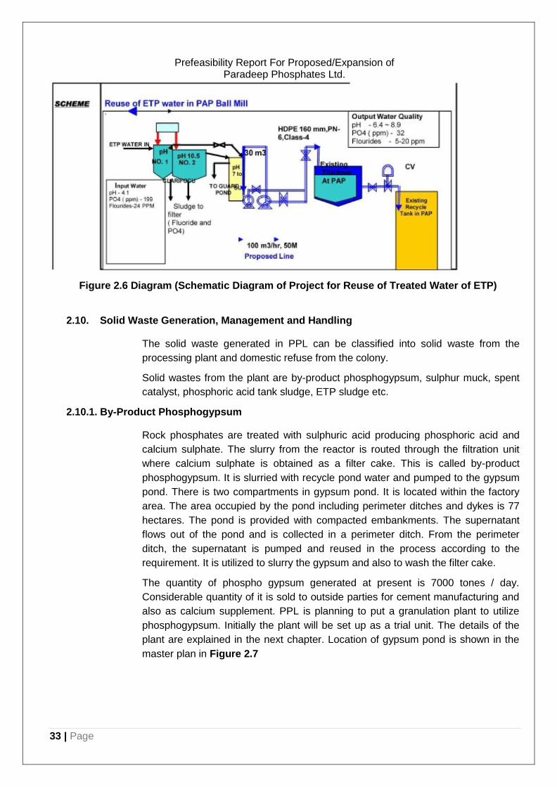
33 | Page
Prefeasibility Report For Proposed/Expansion of Paradeep Phosphates Ltd.
Figure 2.6 Diagram (Schematic Diagram of Project for Reuse of Treated Water of ETP)
2.10. Solid Waste Generation, Management and Handling
The solid waste generated in PPL can be classified into solid waste from the
processing plant and domestic refuse from the colony.
Solid wastes from the plant are by-product phosphogypsum, sulphur muck, spent
catalyst, phosphoric acid tank sludge, ETP sludge etc.
2.10.1. By-Product Phosphogypsum
Rock phosphates are treated with sulphuric acid producing phosphoric acid and
calcium sulphate. The slurry from the reactor is routed through the filtration unit
where calcium sulphate is obtained as a filter cake. This is called by-product
phosphogypsum. It is slurried with recycle pond water and pumped to the gypsum
pond. There is two compartments in gypsum pond. It is located within the factory
area. The area occupied by the pond including perimeter ditches and dykes is 77
hectares. The pond is provided with compacted embankments. The supernatant
flows out of the pond and is collected in a perimeter ditch. From the perimeter
ditch, the supernatant is pumped and reused in the process according to the
requirement. It is utilized to slurry the gypsum and also to wash the filter cake.
The quantity of phospho gypsum generated at present is 7000 tones / day.
Considerable quantity of it is sold to outside parties for cement manufacturing and
also as calcium supplement. PPL is planning to put a granulation plant to utilize
phosphogypsum. Initially the plant will be set up as a trial unit. The details of the
plant are explained in the next chapter. Location of gypsum pond is shown in the
master plan in Figure 2.7
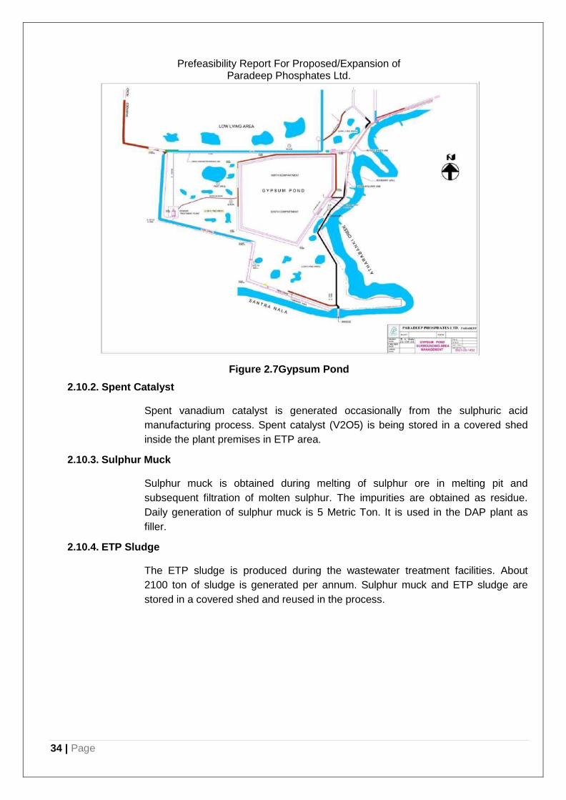
34 | Page
Prefeasibility Report For Proposed/Expansion of Paradeep Phosphates Ltd.
Figure 2.7Gypsum Pond
2.10.2. Spent Catalyst
Spent vanadium catalyst is generated occasionally from the sulphuric acid
manufacturing process. Spent catalyst (V2O5) is being stored in a covered shed
inside the plant premises in ETP area.
2.10.3. Sulphur Muck
Sulphur muck is obtained during melting of sulphur ore in melting pit and
subsequent filtration of molten sulphur. The impurities are obtained as residue.
Daily generation of sulphur muck is 5 Metric Ton. It is used in the DAP plant as
filler.
2.10.4. ETP Sludge
The ETP sludge is produced during the wastewater treatment facilities. About
2100 ton of sludge is generated per annum. Sulphur muck and ETP sludge are
stored in a covered shed and reused in the process.
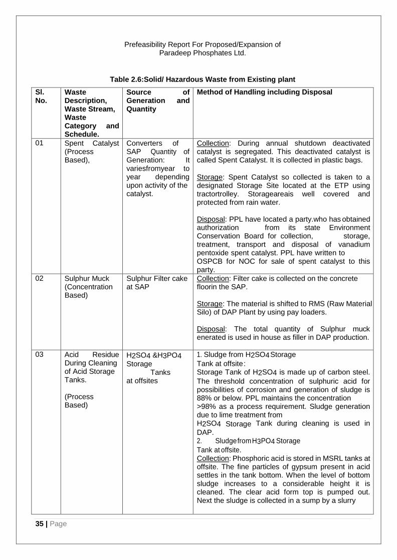
35 | Page
Prefeasibility Report For Proposed/Expansion of Paradeep Phosphates Ltd.
Table 2.6:Solid/ Hazardous Waste from Existing plant
Sl. No.
Waste Description, Waste Stream, Waste Category and Schedule.
Source of Generation and Quantity
Method of Handling including Disposal
01 Spent Catalyst (Process Based),
Converters of SAP Quantity of Generation: It variesfromyear to year depending upon activity of the catalyst.
Collection: During annual shutdown deactivated catalyst is segregated. This deactivated catalyst is called Spent Catalyst. It is collected in plastic bags.
Storage: Spent Catalyst so collected is taken to a designated Storage Site located at the ETP using tractortrolley. Storageareais well covered and protected from rain water.
Disposal: PPL have located a party.who has obtained authorization from its state Environment Conservation Board for collection, storage, treatment, transport and disposal of vanadium pentoxide spent catalyst. PPL have written to OSPCB for NOC for sale of spent catalyst to this party.
02 Sulphur Muck (Concentration Based)
Sulphur Filter cake at SAP
Collection: Filter cake is collected on the concrete floorin the SAP.
Storage: The material is shifted to RMS (Raw Material Silo) of DAP Plant by using pay loaders.
Disposal: The total quantity of Sulphur muck enerated is used in house as filler in DAP production.
03 Acid Residue During Cleaning of Acid Storage Tanks.
(Process Based)
H2SO4 &H3PO4
Storage Tanks
at offsites
1. Sludge from H2SO4 Storage
Tank at offsite : Storage Tank of H2SO4 is made up of carbon steel.
The threshold concentration of sulphuric acid for possibilities of corrosion and generation of sludge is 88% or below. PPL maintains the concentration >98% as a process requirement. Sludge generation due to lime treatment from H2SO4 Storage Tank during cleaning is used in
DAP. 2. Sludge from H3PO4 Storage
Tank at offsite. Collection: Phosphoric acid is stored in MSRL tanks at offsite. The fine particles of gypsum present in acid settles in the tank bottom. When the level of bottom sludge increases to a considerable height it is cleaned. The clear acid form top is pumped out. Next the sludge is collected in a sump by a slurry

36 | Page
Prefeasibility Report For Proposed/Expansion of Paradeep Phosphates Ltd.
pump. From the sump it is pumped to Gypsum Slurry Tank in PAP.
Disposal: The sludge along with gypsum slurry is pumped from the Gypsum Slurry Tank to the Gypsum Pond.
Note: 1 Residues are generated only during tank cleaning. 2. We have not yet discarded any of the storage tanks.
04 Discarded Containers/ Liners usedfor Hazardous Waste/ Chemicals
Discarded Container of Lube Oil Barrel fromSAP,PAP andDAP
Collection: It is collected ati ndividual plant. Storage: Presently allempty barrels are shifted to a designated storage room near Labour Canteen by tractor trolley.
Disposal: Mostly these are used for storing spent oils and disposed off to authorized re-processor along with spent oil.
05 Sludge from Wet Scrubber (Phos Acid Process Based),
Scrubber Settling Pit of PAP
Collection& Storage: In PAP the Fume Scrubber is used for scrubbing fumes coming from various sections of the plant. Scrubbing is done using the Gypsum Pond Recirculation water.
Sludge from the scrubber accumulates in a sump.
Disposal: Sludge from this sump is taken to the Reclaim Pit from where it is flushed to the Gypsum Pond along with the Gypsum Slurry for disposal.
06 Drain & ETP Sludge Generated from sump, filter press. (Concentration Based)
Effluent Drains,
Sump and ETP
Collection: It is collected manually, kept aside along the drain/ ETP Sludge Drying Bed. Once dried the material is shifted to RMS (Raw Material Storage) by tractor trolley.
Storage: It is stored in the RMS.
Disposal: It is used as filler in DAP Plant.
07 Cooling Tower Sludge (Concentration Based)
Cooling Tower Sump of PAP
Collection: Sludge of cooling tower sump of PAP is gypsum in slurry form. The sludge removal is done after dewatering the cooling tower pit. Then the material is shifted to Reclaim Pit.
Disposal: From Reclaim Pit it is flushed to gypsum pond along with gypsum slurry.
08 Spent Resin from DM Plant (Process Based)
DM Plant of CPP
Collection: Spent resin in DM plant is generated only at the time of replacement with fresh resin. The spent resin is collected manually in barrels.
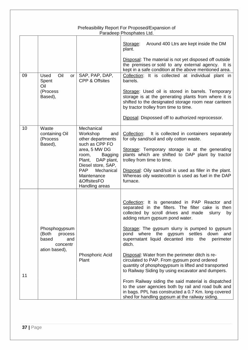
37 | Page
Prefeasibility Report For Proposed/Expansion of Paradeep Phosphates Ltd.
Storage: Around 400 Ltrs are kept inside the DM plant.
Disposal: The material is not yet disposed off outside the premises or sold to any external agency. It is kept in a safe condition at the above mentioned area.
09 Used Oil or Spent Oil (Process Based),
SAP, PAP, DAP, CPP & Offsites
Collection: It is collected at individual plant in barrels.
Storage: Used oil is stored in barrels. Temporary storage is at the generating plants from where it is shifted to the designated storage room near canteen by tractor trolley from time to time.
Diposal: Dispossed off to authorized reprocessor.
10 Waste containing Oil (Process Based),
Mechanical Workshop and other departments such as CPP FO area, 5 MW DG room, Bagging Plant, DAP plant, Diesel store, SAP, PAP Mechanical Maintenance &OffsitesFO Handling areas
Collection: It is collected in containers separately for oily sand/soil and oily cotton waste.
Storage: Temporary storage is at the generating plants which are shifted to DAP plant by tractor trolley from time to time.
Disposal: Oily sand/soil is used as filler in the plant. Whereas oily wastecotton is used as fuel in the DAP furnace.
Phosphogypsum (Both process based and
concentr ation based),
Collection: It is generated in PAP Reactor and separated in the filters. The filter cake is then collected by scroll drives and made slurry by adding return gypsum pond water.
Storage: The gypsum slurry is pumped to gypsum pond where the gypsum settles down and supernatant liquid decanted into the perimeter ditch.
Phosphoric Acid Plant
Disposal: Water from the perimeter ditch is re- circulated to PAP. From gypsum pond ordered quantity of phosphogypsum is lifted and transported to Railway Siding by using excavator and dumpers.
11
From Railway siding the said material is dispatched to the user agencies both by rail and road bulk and in bags. PPL has constructed a 0.7 Km. long covered shed for handling gypsum at the railway siding.
38 | Page
Prefeasibility Report For Proposed/Expansion of Paradeep Phosphates Ltd.
2.7.2. Noise Environment
2.7.2.1. Impact:
Present noise levels in study area are below the standards except near a station
close to Railway crossing. As all the plant equipment are adequate noise control
measures thus there is not much impact to noise in the plant premises. Major
transportation are by either rail or ship.
2.7.2.2. Mitigation Measures:
Towards mitigation measures the following are in practice. Less noise generating
machines/vehicles, maintenance of machines/requirements/vehicles in good
condition, ear muffs or other protecting device or sound proof cabins to employees
near noise generating source. In addition there is development of green belt
barriers and plantation.
2.11. Charter on Corporate Responsibility for Environment Protection (CREP)
Guidelines:
PPL has adopted the Charter on Corporate Responsibility for Environment
Protection (CREP).
2.12. CSR Activities: Peripheral Development:
PPL has carried out numerous CSR activities and contributed significantly for the
peripheral development of the area. A few of such activities recently carried out
are enumerated below.
2.12.1. Construction of Ekta Park :
PPL has developed a children park in Jagatsinghpur collectorate campus. The
same is being maintained by PPL. So far the expenses on this head have been to
the tune of about Rs.5.00 lacs. The annual maintenance cost, which is a running
expense, comes to about Rs.1.00 lac every year.
2.12.2. Health Services:
PPL provides free health services in its own hospital through company doctors and
the services are open to the people of the community around.
PPL organise health camps in nearby villages. Company also conducted Typhoid
vaccination camp, Diabetic camp at its own hospital as well as a general health
check-up camp in village Chanakana of Paradeep Gram Panchayat. The
expenses on this head have been to the tune of Rs.2.5 lacs.
A part of the hospital building has been renovated by spending of about Rs.20.00
lacs and the same facility is being used for providing health services by M/s. Sun
Hospital which is open for public. It may be worth mentioning here that up to date
39 | Page
Prefeasibility Report For Proposed/Expansion of Paradeep Phosphates Ltd.
diagnostic equipments and surgery facility has been made available in this health
centre.
2.12.3. Emergency Relief:
The Company felt it necessary to extend relief at the time of natural calamities,
such as;
Distribution of relief materials to the flood affected people of Kujang and Tirtol
block. The materials included cooked food for about 15,000 people as well as
relief kits containing dry food materials. Company has spent about Rs.9.00 lacs
on this account.
Providing relief materials like utensils, clothing’s, tarpaulin sheets etc. to the fire
victims when there were incidents of fire in nearby localities viz, Balijhara and
Atharbanki Bali Plot and incurred expenses of about Rs.0.55 lacs on this account.
Distribution of insecticides / herbicides spraying machines and organized a
campaign to create awareness among the farmers about know - how for
combating the swarming caterpillars when there was a problem of swarming
caterpillars in Jagatsinghpur district resulting in damage to crops. About Rs.0.65
lacs has been spent on this account.
2.12.4. Distribution of School Kits:
For encouraging the rural children, the Company has undertaken distribution of
school kits containing a good quality school bag, tiffin box, geometry box, pencil
box, note books etc. among 425 students of 4 primary schools of Mangarajpur,
Kothi, Bagadia and Paradeep Garh Gram Panchayats. The expenses on this
head have is to the tune of Rs.2.10 lacs.
2.12.5. Nivedita Orphanage Building :
There is an orphanage called Nivedita Ashram at Patalipanka, about 15 KMs away
from Paradeep. About 100 inmates live there. PPL have constructed a hall with
attached toilets spending of about Rs.2.5 lacs and also distributed warm clothing
amongst the boarders spending about Rs.0.20 lacs.
2.12.6. Canteen Hall at MMITC :
PPL have constructed a canteen hall for the students of Madan Mohan Industrial
Training Centre (MMITC), Mangarajpur at a cost of Rs.4.00 lacs. This facility has
added to the infrastructure of the said institute and is a welfare facility for the
students of the institute
2.12.7. Socio-Cultural Activities:
PPL have been participating in socio cultural activities of the district / locality since
long and is spending about Rs.3.00 lacs per annum on this account.
2.12.8. Developmental Work in Villages:
40 | Page
Prefeasibility Report For Proposed/Expansion of Paradeep Phosphates Ltd.
PPL is keen in developing the living standard of the villagers. Two Gram
Panchayats, Bagadia and Mangarajpur have been identified. Accordingly PPL has
entrusted the task of economic upliftment of these villages to a non-profit
organization called Forum for Integrated Development and Research (FIDR),
Bhubaneswar. They have been undertaking activities related to health, sanitation,
literacy, drinking water, child rights with a focus on the girl child, HIV etc. The
expenditure for the quarter Oct-Dec’ 09 for the purpose has been to the tune of
Rs.5.00 lacs. The total expenditure on the above mentioned CSR activities comes
to Rs.54.05 lacs (approx.).
2.12.9. Plantation and Green Belt Development:
PPL is having 2282.40 Acres of land out of this around 854 Acres of land has been
developed as a green belt and landscaping, which is around 37% of the total land.
Preference has been given for the local and fast growing plant species for the
green belt development; i.eaustralian acacia, paltaforam, Neem, phycus, karanj,
ashoka, kajurina, etc.
2.12.10. Plantation within the Factory:
Attenuation of Noise levels: It is possible to reduce the noise levels by 3–5 dBA per 50m width of the greenbelt. However, a thinner strip of trees with in the industry, outside the administrative and canteen building can reduce the noise resulting from constant movement of trucks, tankers, wagons etc. within the campus. To arrest particulate and gaseous emissions: Aerosols are trapped effectively by trees. Few units from the industry, through in significant in size, would possibly generate aerosols with gases like SO2, NOx
Protection against cyclonic wind: Area of PPL, being cyclonic prone, is protected against damaging action of cyclonic winds. The tree species that exhibit significant check and break force can thus be potentially useful to protect, glass windows and other weak structures within industry from wind force.
2.12.11. Plantation Out Side the Factory:
Existing green belt around the industry is strengthened to improve its efficiency in
reduce the level o pollutant. More than 200 m thick massive plantation has been
done.
2.13. New Projects under Construction
PPL is carrying out expansion (construction / commissioning) of existing plant
facilities. Some of the projects under execution are:
2.13.1 New Gypsum Pond
• New gypsum pond west of existing pond using latest technology from M/S Ardman Associates Inc. Florida, USA is under construction
• Covering about 70-80 hectare area
• New pond will be with geo-textile and HDPE liner.
• HDPE liner from world class manufacturer.

41 | Page
• Use of natural resources to level the surface
Prefeasibility Report For Proposed/Expansion of Paradeep Phosphates Ltd.
3. CHAPTER: PROPOSED PROJECT
This Chapter gives brief details of the proposed expansion project of PPL plant
including land requirement, process, environmental aspects and cost.
3.1. Land Requirement
The Project will be located in the existing compound of PPL is Paradeep in
Jagatsinghpur District, Odisha. It is 90 kms from Cuttack. The site is located at
20º16’56” North Latitude and 86º38’52” East Longitude, west side of Paradeep
Port. The plant encompasses 950 hectares area. Mahanadi River is 5km from the
plant site and meets Bay of Bengal, which is 5.3 km away from the site. Atharbanki
creek is flowing along the boundary wall of the site and is in between Paradeep
Port site and the factory. The expected land requirement for the proposed project
is given below:
Table 3.1 Land Requirement for the Expansion Project
Sl. No. Plants Land
1 COAL HANDLING PLANT 150 Acres
2 GASIFICATION
3 AMMONIA
4 UREA
4 DAP 1.2 Acres
6 NITRIC ACID 13.5 Acres
7 AMMONIUM NITRATE Acres
8 SSP 8.42 Acres
9 ALUMINIUM FLUORIDE 1.16 Acres
Total 174.28 Acres
Note: No fresh land is to be acquired for the expansion project and hence no R&R is involved.
3.2. Process description:
3.2.1. Coal handling plant: Unloading System
(-) 300 mm domestic coal will be received at plant through railway and (-) 150 mm
imported coal will be received through conveyor system from the jetty of Paradeep
port. Two separate dedicated conveyors has been envisaged for power plant and
gasification plant. 7 MMTPA coal assuming 7 MMTPA coal could be domestic or 7
MMTPA could be imported depending upon availability. And. 2 nos. Rota Side
Wagon Tippler has been envisaged for domestic coal unloading through railway
conforming the latest RDSO guideline. Wagon tippler will discharge the coal at
wagon tippler hopper. From the hopper material shall be extracted by apron feeder
and which will feed to the subsequent conveyors for screening and crushing the
incoming coal at desired output size. Crushed material can be directly fed to

42 | Page
gasification plant simultaneously or coal can be stacked at stockpile through
individual Stacker Reclaimer. Imported coal shall be received at plant through
conveyor shall be stacked at shed. From the shed, imported coal shall be dozed to
reclaim hopper by bull dozer. Vibrating feeder will extract the material from the
hopper and shall feed to conveyor. Domestic coal coming from wagon tippler
hopper and imported coal coming from reclaim hopper can be blended at required
proportion at junction tower where both the conveyor is feeding to the
same conveyor. Imported coal capacity can be controlled through vibrating feeder
and domestic coal capacity can be controlled through apron feeder. There will be a
layer of domestic coal over which another layer of imported coal will exist. In the
process subsequent blending of coal will be carried out at transfer chutes, crusher
house and junction tower.

43 | Page
Prefeasibility Report For Proposed/Expansion of Paradeep Phosphates Ltd.
Figure 3.1PFD Coal Handling Plant
3.2.2. Ammonia plant (coal based) :[Capacity – 2200 MTPD] (Description of 1 stream, PPL
intends for 3 streams)
The process utilizes a single gasifier block with two gasifiers (2+1) to provide
syngas for ammonia production and for power generation. The following block
flow diagram shows the arrangement of unit blocks.
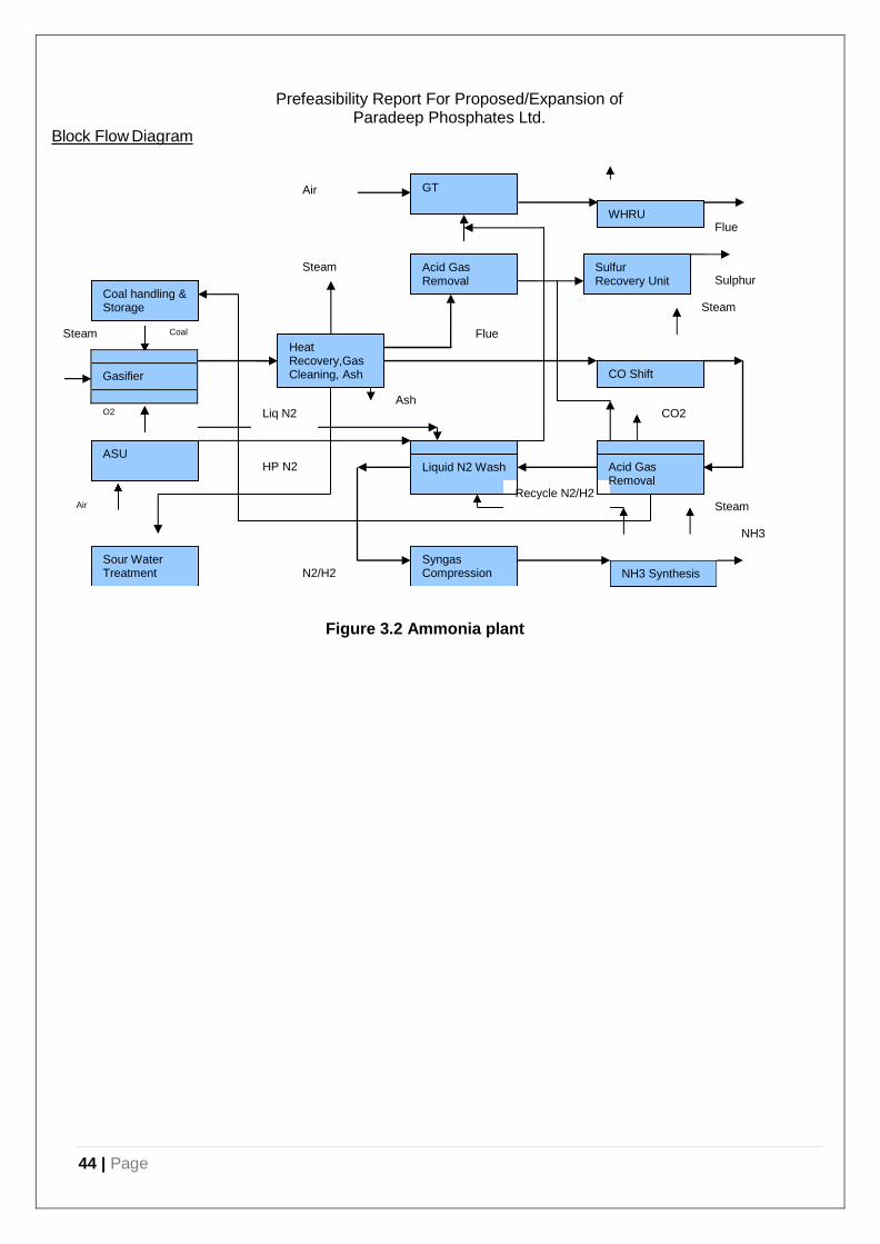
44 | Page
Flue
Steam Sulphur
Steam
Steam Coal Flue
Ash O2 Liq N2 CO2
HP N2
Recycle N2/H2 Air Steam
NH3
N2/H2
GT
WHRU
Acid Gas Removal
Sulfur Recovery Unit
Coal handling & Storage
CO Shift
Heat Recovery,Gas Cleaning, Ash
Acid Gas Removal
ASU Liquid N2 Wash
Sour Water Treatment
Syngas Compression NH3 Synthesis
Block Flow Diagram
Prefeasibility Report For Proposed/Expansion of Paradeep Phosphates Ltd.
Air
Gasifier
Figure 3.2 Ammonia plant
Prefeasibility Report For Proposed/Expansion of Paradeep Phosphates Ltd.
Coal Preparation:
The coal preparation is designed at the coal handling plant itself to
prepare the coal feed to the required standard for the gasification plant.
The coal from the coal handling plant area is conveyed to a kiln type
dryer that contacts the coal with heated air, ina way reducing the
moisture content in it.
A bucket conveyor lifts dried coal to the top of the coal hoppers.
Air Separation Unit
The Air Separation Unit (ASU) supplies high pressure oxygen to the
gasifiers and the Sulfur Recovery Unit (SRU). The ASU also supplies
nitrogen for the ammonia process, utility usage, liquid for storage and the
Nitrogen Wash Unit. The ASU produces O2 and N2 via cryogenic
distillation and generates its own refrigeration by compression of the inlet
air. The inlet air compressor is one of the largest drivers on site and can
be either electric or steam powered. At this time the air compressor is
listed as electric.
Gasifier Feed System
The gasifier feed system consists of weight bins, conveyors, and lock
hopper systems that supply the gasifier with coal at pressure. Carbon
dioxide from the acid gas removal system (AGS) is used as transport gas
to improve the syngas yield. The coal feed is pressurized in a lock
hopper system and metered into the gasifier using a rotary or screw
feeder. Steam and Oxygen are injected at the bottom of the gasifier,
beneath the grid. Together they provide the energy to fluidize the
gasification mixture.
Gasification
Within the fluidized bed the coal reacts with steam and oxygen.
The process accomplishes four important functions; it decakes,
devolatilizes, and gasifies the feedstock and if necessary,
agglomerates and separates ash from the reacting coal. At the specified
operating conditions, coal is gasified rapidly to produce a synthesis gas
product consisting of hydrogen, carbon monoxide, water vapor,
and methane. Additionally the gas contains small amounts of ammonia,
hydrogen sulfide, and other impurities. The syngas exits the top of the
gasifier through a refractory lined to the inlet of the primary cyclone.
49 | P a g e
Fines Recovery
The primary fines recovery and recycle system consists of two cyclones
in series, the primary and secondary cyclones. The cyclones collect
most of the fines from the gas stream leaving the gasifier. The primary
cyclone is refractory lined due to the temperature. Syngas from the
Prefeasibility Report For Proposed/Expansion of Paradeep Phosphates Ltd.
primary cyclone enters the secondary cyclone which is similarly
refractory lined. The fines collected in the cyclones are returned to the
fluidized bed of the gasifier by means of a dip-leg.
Ash Disposal
Coarse ash is removed from the bottom of the gasifier, cooled, and
discharged through a lock hopper system. Ash is conveyed by water
cooled screw conveyors for further cooling and discharged to an ash
storage silo. Ash from the silo is mixed with water in a pug mill before
loading on a truck for disposal.
Waste Heat Recovery
The heat recovery steam generator (HRSG) increases the plant’s
efficiency by generating steam from the hot syngas leaving the
secondary cyclone. The HRSG is a natural circulation boiler which has a
single drum and steel structure. The syngas flows sequentially through
the steam generator section, the superheater, and the economizer
before leaving the bottom of the HRSG. Steam produced by the HRSG
is used as feed to the gasifier and produced in excess for use elsewhere.
Syngas Clean-up
The cool syngas from heat recovery passes to a third high efficiency
cyclone and then to a ceramic/metal filter for further dust removal. The
collected fines are recycled to the gasifier through the fines management
system. The syngas is then washed in counter current scrubber to
remove the residual solids. Evaporation of water in the scrubber cools
the gas and concentrates the water so a continuous blow-down is
required.
Fines Handling
Dry fines collected from syngas clean-up are routed to a fines silo
through a lock hopper system. They are collected in the silo and returned
to the gasifier. The system is referred to as the Fines Management
System and is included to maximize the carbon conversion. Normally all
fines are recycled to the gasifier where they agglomerate and are
discharged with coarse ash.
Sour Water Treatment
The blow-down water from the syngas scrubber is saturated with
hydrogen sulfide that is produced in the gasifier from sulfur in the coal.
The blow-down is stripped in packed column and the overhead gas sent
to the sulfur recover unit. The stripped bottoms is cooled and treated by
a clarifier to settle the ash. The solids containing underflow is used to
wet the dry ash in the pug mill during loading. Clarified overflow is
reused in the process if possible or treated for discharge.
50 | P a g e
Prefeasibility Report For Proposed/Expansion of Paradeep Phosphates Ltd.
Sour Gas Shift
Clean syngas from the scrubber is mixed with steam prior to entering the
three stage sour gas shift reactors. The syngas from the gasifier is
rich in hydrogen, carbon monoxide, and carbon dioxide. The shift
reactors convert carbon monoxide and steam to more hydrogen and
carbon dioxide. The first shift reactor is operated at high temperature
to encourage the rate of conversion. The second two reactors operate at
reduced temperatures to encourage complete reaction of the carbon
monoxide. Heat exchange at the exit of the first reactor produces high
pressure steam which can be used to drive power turbines.
After the shift reactors a mercury guard bed is provided. The guard bed
is filled with sulfur impregnated activate carbon. Any mercury present
from the coal is reacted with the sulfur and retained.
Acid Gas Removal(AGR)
At this point in the process the syngas contains Hydrogen Sulfide
(H2S) and approximately 40 mole percent carbon dioxide (CO2). These
acid gas components are removed in a two step absorption process.
Selexol is a UOP licensed process that absorbs acid gases and upon
regeneration releases the H2S and CO2 in two separate streams. This
allows the H2S to be recovered in the SRU and the CO2 to be safely
vented. AGR unit includes a refrigeration package for chilling the
absorption solution. The SES based gasifier utilizes CO2 to inject coal
into the gasifier. The CO2 affects the reaction equilibrium in the gasifier
and improves efficiency of the system. CO2 from the AGR is at low
pressure, therefore a CO2 compressor has been provided.
Nitrogen Wash
Ideally the syngas feed to the ammonia synthesis loop has a ratio
of 3 moles of hydrogen per mole of nitrogen, and no other components
present. Following the AGR there remains trace impurities in the
syngas that include methane, water, carbon monoxide, and carbon
dioxide. Oxygen containing components must be removed because
they will oxidize the ammonia synthesis catalyst and reduce its
activity. Methane in the synthesis loop is an inert that accumulates and
must be purged. The nitrogen wash unit accomplishes both cleaning of
the syngas and addition of nitrogen to produce a stoichiometric mixture.
The syngas to the nitrogen wash unit is first dried in molecular sieve
dryers to remove all traces of water. The dry syngas is cooled and then
washed by direct contact with liquid nitrogen. Nitrogen and hydrogen
have the lowest boiling point of the components present, so the
liquid nitrogen stream from the tower contains all the unwanted
components. The syngas from the top of the tower is virtually pure and in
the correct hydrogen to nitrogen ratio.
51 | P a g e
Prefeasibility Report For Proposed/Expansion of Paradeep Phosphates Ltd.
The nitrogen wash unit also recovers purge from the ammonia synthesis
loop. The liquid nitrogen wash stream is vaporized for heat recovery and
then sent as fuel to the gas turbine.The technology that this system is
based upon produces the fuel gas at relatively low pressure, therefore a
fuel gas compressor is provided.
Synthesis Gas Compression
Syngas from the Nitrogen Wash Unit is ready for addition to the
ammonia synthesis loop as make-up. The syngas is compressed to
approximately 155 barg by the Syngas Compressor. The last stage of
the compressor is the synthesis loop circulator. The compressor is
driven by HP superheated steam generated by the process.
Ammonia Synthesis
Hydrogen and Nitrogen are reacted to produce ammonia in a fixed bed
converter. The converter is multi-staged with inter-cooling. Each bed
is filled with promoted iron catalyst. Converter effluent is cooled by
producing steam and preheating boiler feed water. Make-up gas and
recycle gas from the syngas compressor is preheated by cross exchange
with converter effluent. Converter effluent is further cooled by cooling
water. The reactor effluent is then chilled by ammonia refrigeration in two
stages to produce a liquid ammonia stream. The separated syngas is
warmed by cross exchange with reactor effluent and recycled by the
syngas loop circulator Ammonia Refrigeration
The liquid ammonia from the synthesis loop is flashed at two levels to
provide the refrigerant to the synthesis loop chillers. The refrigeration
compressor recovers the refrigerant ammonia vapors by
recompressing and condensing the ammonia with cooling water. The
refrigeration compressor is driven by HP steam turbine.
The refrigeration system is configured for production of ammonia at
warm conditions for storage at ambient temperatures and pressure.
The refrigeration system can be configured to produce liquid ammonia at
atmospheric pressure and -33°C for storage in atmospheric tanks.
Atmospheric pressure storage requires additional refrigeration and
power.
Fuel Gas Treatment
A portion of syngas from the gasifier block is used as fuel for power
generation. The fuel gas contains sulfur from the coal as Hydrogen
Sulfide. There is currently no need to remove carbon dioxide from the
fuel. Therefore the amine system for treating the fuel gas, MDEA, is
selective for H2S. The fuel gas is scrubbed by amine solution in an
absorber. The amine solution is stripped in a second tower to regenerate
the solution and produce an H2S rich stream.
52 | P a g e
53 | Page
Prefeasibility Report For Proposed/Expansion of Paradeep Phosphates Ltd.
Sulfur Recovery Unit
The sulfur laden streams from fuel gas treatment and from the AGR are
combined and processed by the Sulfur Recovery Unit (SRU). The SRU
is a package unit also referred as a “Claus Unit.” The sulfur laden
stream is burned over catalyst that reduces the H2S to molten elemental
sulfur. Molten sulfur from the unit would be consumed in the sulfuric acid
plant already operating at the site. The SRU produces some steam for
export.
Electric Power Generation
Power for the entire plant site, 120 MW, will be produced by a gas
turbine driven generator (GTG). Fuel gas from fuel gas treating will
be combined with the nitrogen/methane rich fuel from the fuel gas
compressor. The GTG drives its own air compressor for combustion
air. The exhaust from the gas turbine will be used to generate and
superheat HP steam. To meet a discharge limit of 25 ppm of NOx, the
gas turbine vendor has included a steam diluents flow of 77.6 Tons per
hour. The steam flow has been added to the steam balance and
produces approximately 19 additional MW of electric power.
At this time no other special equipment is included for boosting power
generation (e.g. inlet air chilling, fuel gas saturation) or for environmental
control (e.g. selective catalytic reduction). Since natural gas is not
available and the gasification block cannot operate continuously, the
operation of the GTG on diesel fuel oil as an alternate fuel is
anticipated.
Steam System
The steam system recovered as waste heat by cooling process streams
and powers some major equipment. Steam is generated at 103 barg by
process heat in the CO shift area, the ammonia synthesis loop, and the
waste heat recovery unit on the exit of the GTG. HP steam is also
superheated by the waste heat recovery unit. The superheated HP
steam is let-down to MP steam through the Syngas Compressor Turbine.
To provide sufficient HP steam, supplemental fuel (treated syngas) is
fired in the WHRU.
MP steam at 41 barg is generated and superheated by the gasifier unit.
The MP steam is used as feed to the gasifier, but a significant amount of
steam is exported for use by the rest of the plant. The SRU also
produces some saturated MP steam for export. MP steam is also used
as process feed in the CO shift area, power for the Syngas
Compressor and Ammonia Refrigeration Compressor. Both compressor
turbine drives are condensing type.

54 | Page
Prefeasibility Report For Proposed/Expansion of Paradeep Phosphates Ltd.
LP steam at 10 barg is provided by letdown from the MP. The steam is
used in the Sour Water Stripper and Sulfur Pit Eductors. LLP steam at
2 barg is also provided. The some steam is provided by flashing
condensate from process heaters. The Deaerator is the largest user.
Condensate and Boiler Feed Water Systems
The deaerator is the centre of the condensate and boiler feed water
systems. The packed section of the deaerator strips dissolved gases
from the water entering the deaerator. The deaerator collects
condensate from the process heaters, condensate from the turbine
condensers, and fresh demineralized water for make-up.
The deaerator drum is the reserve of treated boiler feed water available
for feed to the various boilers. Boiler feed water is provided at the
appropriate pressure by the HP BFW Pump and the MP BFW Pump.
Both pumps are currently included as electric powered but BFW pumps
are usually the first pumps to be made steam turbine drive.
3.2.3. Urea plant : [Capacity – 3850 MTPD]
3.2.3.1. Main Plant Details
The capacity of Urea plant has been considered as 3850 MTPD. The
most popular and widely used urea process technologies at present
are ammonia stripping process of Saipem (SNAM Progetti) and CO2
stripping process of Stamicarbon. The ACES process of M/s. Toyo, has
also been adopted in quite a number of plants across the globe, and is
very much in commercial operation. However, for this process, the
reference list is much shorter. In terms of overall efficiency, plant cost,
specific consumption etc., all the three processes are very much
competitive. The SnamProgetti ammonia stripping process has a major
share of the urea plants in India with very good operational records in
terms of achieving target production with very high on-stream
efficiencies. The share of Snam Progetti is around 70% of the total urea
capacity installed all over the world in last 10 years.
The raw material Ammonia and CO2 shall be provided at battery limit.
The plant will have a normal on stream efficiency of 330 days.
3.2.3.2. Plant Description (Urea Plant)
Urea Plant has many renowned technologies which are equally
comparable with respect to plant cost and energy consumption. For the
proposed study, Saipem’s ammonia stripping process technology has
been considered as depicted in below given figure3.3.
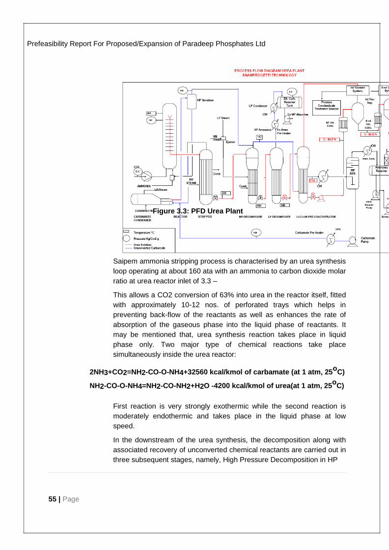
55 | Page
Prefeasibility Report For Proposed/Expansion of Paradeep Phosphates Ltd
Figure 3.3: PFD Urea Plant
Saipem ammonia stripping process is characterised by an urea synthesis
loop operating at about 160 ata with an ammonia to carbon dioxide molar
ratio at urea reactor inlet of 3.3 –
This allows a CO2 conversion of 63% into urea in the reactor itself, fitted
with approximately 10-12 nos. of perforated trays which helps in
preventing back-flow of the reactants as well as enhances the rate of
absorption of the gaseous phase into the liquid phase of reactants. It
may be mentioned that, urea synthesis reaction takes place in liquid
phase only. Two major type of chemical reactions take place
simultaneously inside the urea reactor:
2NH3+CO2=NH2-CO-O-NH4+32560 kcal/kmol of carbamate (at 1 atm, 25o
C)
NH2-CO-O-NH4=NH2-CO-NH2+H2O -4200 kcal/kmol of urea(at 1 atm, 25o
C)
First reaction is very strongly exothermic while the second reaction is
moderately endothermic and takes place in the liquid phase at low
speed.
In the downstream of the urea synthesis, the decomposition along with
associated recovery of unconverted chemical reactants are carried out in
three subsequent stages, namely, High Pressure Decomposition in HP
56 | Page
Prefeasibility Report For Proposed/Expansion of Paradeep Phosphates Ltd.
Stripper, MP Decomposition in MP Decomposer and, finally, LP
Decomposition in LP Decomposer. The decomposition reaction is the
reverse of the first reaction one as shown above, viz.,
NH2-CO-O-NH4=2NH3+CO2 -Heat
As can be inferred from the aforesaid chemical equation, the reaction is
favoured by reducing pressure and/or adding heat.
The urea reactor effluent solution enters the stripper, operating at
the same pressure level as urea reactor, where a fair part of the
unconverted carbamate is decomposed, by heat liberated from
condensing steam on the shell side along with combined stripping action
of excess NH3. As a result the overall yield of the HP synthesis loop
referred to conversion of CO2 fed for urea synthesis, is as high as 83 to
85% (on molar basis).
Downstream of the stripper, the residual carbamate solution and
ammonia are recovered in two recycle stages operating at 18 ata
(namely MP section) and 5 ata (namely LP section) respectively.
Ammonia and carbon dioxide vapours from the stripper top, after mixing
with the carbonate recycle solution from MP section, are condensed, at
the same pressure level of the stripper itself, in the HP carbamate
condenser, thus producing LP steam which is used in downstream
sections. After separating the inert gases which are passed to MP
section, the carbamate solution is finally recycled to the reactor bottom
by means of a liquid/liquid ejector, which exploits HP ammonia feed to
reactor as the motive fluid.
The liquid/liquid ejector and the kettle-type HP carbamate condenser as
mentioned above, are arranged in a horizontal layout which is
considered to be one of the main features of Saipem process.
Waste heat recovery from process streams in some parts of the process
layout have been introduced as a part of recent modifications, thus
allowing considerable savings in overall steam and fresh water
consumption, viz.:
❖ HP ammonia to urea reactor preheating with off-gas from LP decomposition stage
❖ Heat to vacuum preconcentrator with off-gas from MP decomposition stage
❖ Total recovery of process condensate as boiler feed water.
Urea plant based on Saipem urea technology is, characterised by the
following main process steps:
57 | Page
Prefeasibility Report For Proposed/Expansion of Paradeep Phosphates Ltd.
❖ Urea Synthesis and NH3, CO2 recovery at high
Pressure
❖ Urea Purification and NH3, CO2 recovery at medium and low
Pressure
❖ Urea Concentration
❖ Urea Prilling
❖ Waste Water Treatment
❖ Auxiliary Installation
❖ Steam Networks
❖ Flushingnetworks
Urea Synthesis and NH3, CO2Recovery at High Pressure
Urea is produced by synthesis from liquid ammonia and gaseous carbon
dioxide. In the urea reactor, the ammonia and carbon dioxide react to
form ammonium carbamate, a portion of which dehydrates into urea and
water. The reactions are as follows:
2NH3+CO2 ↔ NH2COONH4
NH2COONH4 ↔ NH2CONH2+H2O
The conditions prevailing inside urea synthesis reactor, i.e., (T = 188-
190oC, P =160 ata), favours reaction rate for the first reaction which
occurs rapidly and goes to completion. The second reaction is very slow
and reaction rate of second reaction determines the reactor volume.
The fraction of ammonium carbamate that dehydrates is determined by
the ratios of the various reactants, the operating temperature and the
residence time in the reactor.
The mole ratio of ammonia to carbon dioxide is maintained around 3.3 -
3.6. The mole ratio of water to carbon dioxide is maintained around 0.5 -
0.7.
The liquid ammonia feed provided at BL at around plus 20oC, to urea
plant, is filtered through NH3 filters which, then enters urea plant via NH3
recovery tower and is collected in the ammonia receiver tank. From
receiver, it is drawn and pumped to about 24 ata pressure by means of
centrifugal ammonia booster pump. Part of this ammonia is sent to
58 | Page
Prefeasibility Report For Proposed/Expansion of Paradeep Phosphates Ltd.
medium pressure absorber, the remaining part enters the high pressure
synthesis loop.
The ammonia is pumped by centrifugal HP ammonia pump to the urea
synthesis loop, at a pressure of about 230 ata. Before entering the
reactor, ammonia is heated in the ammonia preheater and used as
propelling fluid in the carbamate ejector is propelled up to the synthesis
pressure.
The liquid mixture of NH3 and carbamate enters the urea reactor from
the bottom where it reacts with the compressed carbon dioxide feed.
Carbon dioxide from regenerator of decarbonation section of ammonia
plant is drawn as feed to urea plant via CO2 booster compressor, and
enters the suction of CO2 compressor at around 1.4-1.5 ata and 40oC
where it is compressed to a pressure of about 160 ata.
A small quantity of air is added to carbon dioxide feed at CO2
compressor suction in order to passivate the stainless steel surfaces of
HP loop equipment, thus protecting them from corrosion from the
reactants and reaction products.
The reaction products, leaving the reactor, flow to the upper part of
stripper which operates at about 150 ata. It is a vertical falling film
decomposer in which the liquid is distributed on the heating surface as a
film and flows by gravity to the bottom. The HP stripper is essentially a
vertical shell & tube exchanger with heating medium on the shell side,
with an extended tube side top channel head specially designed for
permitting uniform distribution of carbamate/urea solution over the
top/inlet tube sheet. In fact, each tube has an insert-type distributor
(ferrule) designed to distribute the feed uniformly around the tube wall in
the form of a film. The holes of the ferrule act as orifices and their
diameter and liquid head control the flow rate. As the liquid film flows
downwards, it is heated and decomposition of carbamate and surface
evaporation occurs. The carbon dioxide content of the solution is
reduced by the stripping action of the ammonia as it boils out of the
solution. The vapour formed (essentially ammonia and carbon dioxide)
flows out from the top of the tube. The carbamate decomposition heat is
supplied by condensation of saturated steam at 23 ata.
The mixed stream of overhead gases from the stripper and the
recovered solution from the bottom of medium pressure absorber enters
carbamate condenser where the condensing components of overhead
gases other than the non-condensable get condensed and the solution is
recycled back to the urea reactor through carbamate ejector.

59 | Page
Prefeasibility Report For Proposed/Expansion of Paradeep Phosphates Ltd.
Condensation of overhead gases from stripper at a high pressure and
temperature permits production of steam at 6 ata in the carbamate
condenser and steam at 4.5 ata in the carbamate condenser.
The non-condensable gases coming out from the top of the carbamate
separator consist of inert gases (passivation air plus inert with CO2 from
B.L) containing little quantities of NH3 and CO2, which are sent directly
to the bottom of the medium pressure decomposer.
Urea Purification and NH3, CO2recovery at Medium & Low Pressures
Urea purification and associated recovery of the overhead gases take
place in two different pressure stages as mentioned below:
❖ 1st
stage at 18ata pressure
❖ 2nd stage at 5 ata pressure
The exchangers where urea purification takes place are generally termed
as decomposers because in these equipment the residual carbamate
present in urea solution, are decomposed.
1st
Purification and Recovery Stage at 18atm Pressure
The solution, with low residual CO2 content leaving the bottom of the
stripper is expanded to a pressure of around 18 ata and enters the upper
part of medium pressure decomposer. This equipment is mainly divided
into three sections.
Top separator: The released flash gases are removed here before the solution enters the tube bundle.
Falling film type decomposer: The carbamate solution is decomposed here. Required heat is supplied by means of condensing steam at 6.0ata (in the upper part of the shell) and sub-cooling of steam coondensate flowing out of the stripper steam saturator (in the lower part of the shell).
Urea Solution Holder: Purified urea solution obtained from the1st stage and having a concentration ofaround60-63%wt., is collected here.
The NH3 and CO2 rich gases, leaving the top of separator are sent to
the shell side of the falling film vacuum pre concentrator, where they are
partially absorbed in aqueous carbamate solution coming from the
recovery section at 5 ata.
The total heat generated in the shell side, due to
condensation/absorption/reaction of the reactants, is removed by
evaporation of urea solution, coming from the 2nd purification step. In the
process, concentration of urea solution increases to 84-86% wt., thereby
resulting in considerable saving of LP steam in the vacuum concentration
stage.
60 | Page
Prefeasibility Report For Proposed/Expansion of Paradeep Phosphates Ltd.
From the shell side of vacuum pre concentrator, the mixed phase is sent
to medium pressure condenser where CO2 is almost totally absorbed
and condensation/ reaction heat is removed by cooling water coming
from ammonia condenser.
The mixed phase effluent from MP condenser flows to medium pressure
absorber bottom where the released gaseous phase moves upwards
across tower and enters the rectification section. The medium pressure
absorber tower is fitted with bell cap trays. The bottom section of the
tower is used for CO2 absorption while the top part of the tower is
utilised for NH3 rectification.
Pure ammonia is added as reflux to the top trays in order to balance the
energy entering the column, and to remove residual CO2 and H2O
contained in the rising stream of gaseous ammonia and inerts. Reflux
NH3 is drawn from the ammonia receiver and sent to column by means
of ammonia booster pump.
Saturated ammonia vapour along with inert, containing few ppm of CO2
(20-100 ppm), and coming out from top of the rectification section, is
partially condensed in the ammonia condenser and the condensate is
sent to the ammonia receiver.
Uncondensed vapours, saturated with ammonia, from ammonia receiver
goes to ammonia recovery tower where additional amount of ammonia is
condensed out from the vapours by scrubbing with liquid ammonia
coming from the B.L.
The gaseous stream, leaving from top of ammonia recovery tower enters
at the bottom of medium pressure falling film absorber. The residual
ammonia content in the gas is drastically reduced by absorption in a
counter current downward flow of ammonia water solution. Heat
generated by ammonia absorption, increases the temperature of
descending liquid, thereby tending to impede further ammonia
absorption. To maintain the temperature at a reduced level, the heat of
absorption is removed by cooling water flowing through the shell side of
MP ammonia absorber.
The MP inert washing tower connected to the upper part of MP absorber
consists of three valve trays where the inert gases are subjected to last
stage of washing by means of pure water. Here the ammonia content of
rising gas stream is minimal and consequently the temperature is less
sensitive to absorption heat. Inerts containing traces of ammonia are
finally vented through the vent stack.
From the bottom of MP ammonia absorber the NH3-H2O solution is
recycled back to the medium pressure absorber by means of a
centrifugal pump.

61 | Page
Prefeasibility Report For Proposed/Expansion of Paradeep Phosphates Ltd.
The MP absorber bottom effluent is recycled by means of
centrifugal HP carbonate solution pump to the synthesis recovery
section.
nd
2 Purification and Recovery Stage at 5 ata
The solution, with very low residual CO2 content, leaving the bottom of
the MP decomposer is expanded to a pressure of 5 ata and enters the
upper part of low pressure decomposer, which is mainly divided into
three sections:
Top separator: Released flash gases are removed here, before the solution enters the tube bundle.
Falling film type Decomposer: Decomposition of carbamate solution is carried out here and the required heat is supplied by means of condensing LP steam at 6 ata (saturated).
Urea Solution Holder: Purified urea solution obtained from the 2nd stage and having a concentration of around 69-71%wt., is collected here.
The gases leaving the top of separator are first mixed with the vapours
coming from rectification section of the distillation tower and
subsequently sent to shell side of HP ammonia preheater where they are
partially condensed. The condensation heat is recovered by preheating
of HP liquid ammonia (feed to urea reactor) in the tube side.
The ammonia pre heater shell side effluent is sent to LP condenser
where the remaining NH3 and CO2 vapours are totally condensed.
Condensation heat is removed by cooling water flowing in the tube side.
The carbonate solution at the exit of LP condenser is collected in
carbamate solution accumulator. The carbonate solution is recycled back
to the MP absorber, bottom by means of centrifugal, MP carbonate
solution pump through the shell sides of vacuum pre concentrator and
MP condenser respectively.
It is also possible to use part of the low-pressure carbamate solution as
reflux in rectification section of distillation tower.
The carbonate solution accumulator is designed with a low pressure-
washing tower in order to help the pressure control of 2nd recovery
stage.
Urea Concentration
In order to prill urea, it is necessary to concentrate the urea solution up to
99.7% by wt. For this, two vacuum concentration stages are provided.
The solution leaving the LP decomposer bottom having about 70 % wt.
urea, is sent first to the tube side of vacuum pre-concentrator and then
62 | Page
Prefeasibility Report For Proposed/Expansion of Paradeep Phosphates Ltd.
pumped by to 1st vacuum concentrator both operating at a pressure of
0.33 ata.
The urea solution leaving the bottom of LP decomposer is
expanded to the pressure of 0.33 ata and enters the upper part of
vacuum pre-concentrator.
The vacuum preconcentrator is mainly divided in three parts:
Top Separator: Released flash gases are removed before the solution enters
the tube bundle. Vapours are extracted by1st
vacuum system:
Falling Film Type Evaporator: In evaporator, low residual carbonate is decomposed and water is evaporated. The required heat is supplied by partial condensation (in the shell side) of over head gas coming from the MP Decomposer;
Bottom Liquid Holder: Urea solution having concentration 84-87%wt., is collected here.
The urea solution leaving the vacuum pre concentrator holder is sent by
urea solution pump to the bottom of 1st vacuum concentrator operating
at around the same pressure (i.e. 0.33 ata) of tube side.
Saturated steam at 4.5 ata is supplied to the1st vacuum concentrator
shell side to concentrate the urea solution flowing in the tube side.
The mixed phase of gas and liquid coming out from the process side of
1st vacuum concentrator enters 1st vacuum separator from where
vapours are again extracted by the 1st vacuum system while the urea
melt (~95% by wt.), enters the bottom of 2nd vacuum concentrator
operating at a pressure of 0.03 ata by gravity flow.
Saturated steam at 4.5 ata is supplied to the 2nd vacuum concentrator
shell side to concentrate the urea solution flowing in the tube side.
The mixed phase of gas and liquid coming out from the process side of
2nd vacuum concentrator enters 2nd vacuum separator, from where
vapours are extracted by the 2nd vacuum system while the urea melt
(~99.75% by wt.) is sent to prilling section by means of urea melt pumps.
Urea Prilling
Urea melt leaving the 2nd vacuum separator holder is sent to the prilling
bucket by means of a centrifugal pump.
Droplets of molten urea from the prilling bucket fall downwards along the
natural draught prilling tower and gets solidified and cooled while
encounters a counter current air flow. The solid prills are collected at the
centre of prilling tower bottom by means of the conical double arm rotary
scrapper and through a conical hopper, they fall on prilling tower belt
conveyor.

63 | Page
Prefeasibility Report For Proposed/Expansion of Paradeep Phosphates Ltd.
The urea lumps separator downstream removes any urea lumps or
agglomerates which are eventually discharged directly and dissolved in
the underground urea close drain Tank. Finally, the urea product is sent
to B.L by belt conveyor.
Waste Water Treatment
This section treats the water containing NH3-CO2 and urea coming out
of vacuum system, so as to have an almost NH3-CO2-urea free process
condensate to be sent to B.L.
The process water containing NH3, CO2 and urea, coming from the
vacuum systems, is collected in the process condensate tank, together, if
necessary, with the drain solutions accumulated into underground
carbonate close drain tank and fed to process condensate tank by
means of pump. From process condensate tank the condensate is
pumped by means of distillation tower feed pump to the upper part of
distillation tower.
Before entering the column, the process condensate picks-up heat
from the purified condensate leaving the bottom of distillation column
itself, by means of distillation tower preheater.
The distillation column is provided with 55 nos. of trays and is separated
into two main portions by a chimney tray between the trays numbered
(from the bottom) 35 and 36.
Column process conditions are: Pressure (top) : 5 ata
Temperature (top) : 130o
C
The condensate from the chimney tray is pumped by centrifugal
hydrolyser feed pump to urea hydrolyser where process conditions are
suitable to decompose urea into CO2 and NH3. In the hydrolyser live
steam is added so as to provide enough heat to decompose urea.
Hydrolyser process conditions are:
< Pressure : 35 ata
< Temperature : :2 35oC
< Steam availableat B.L :Temp. 380oC, press. 45-42 ata
The vapours coming out from the hydrolyser as well as the vapours from
the top of the distillation tower are mixed with the LP decomposer
overhead gas, upstream of ammonia preheater for heat recovery.
The hydrolysed condensate leaving the bottom of the hydrolyser is
cooled by passing through hydrolyser preheater before entering
64 | Page
Prefeasibility Report For Proposed/Expansion of Paradeep Phosphates Ltd.
distillation tower at the bottom of chimney tray where the final NH3 and
CO2 stripping take place. LP steam (at a press. of 6 ata), injected
directly at the column bottom, provides the necessary driving force for
stripping.
The purified process condensate leaves the column bottom at 155oC
and subsequently cooled to around 50oC in the following manner:
❖ Distillation tower feed preheating by means of preheater.
❖ Process condensate cooler.
The contaminants (i.e. NH3-CO2-urea) in this treated water are reduced
to few ppm.
During start-up and upsets in waste water treatment section, the
processed condensate is generally recycled to the process condensate
tank until specified ppm of NH3 and urea are obtained.
Auxiliary Installation
In addition to main plant the following auxiliary installations are being
provided for its smooth operation.
Flare System
The flare system shall comprise of the following two flares:
< Continuous Flare from MP section.
< Discontinuous Flarefrom the following streams:
- Vents from tanks
- Process Condensate Treatment Section vent
- Low Pressure Section vent
- High Pressure Section vent
Carbonate Close Drain Tank
Tank is used to collect the drain solutions from various section of urea
plant. These solutions by means of pump are sent to the process
condensate tank for further processing in the waste water treatment
section.
Urea Solution Tank
Tank is used to collect both the 70-75% urea solution in case of tripping
of concentration sections, or urea melt in case of prilling section failure.

65 | Page
Prefeasibility Report For Proposed/Expansion of Paradeep Phosphates Ltd.
In the same tank it has also been envisaged to recover the urea solution
recycle coming from urea close drain tank after being filtered through
filters.
Urea Solution Recovery Pumps
This pump is used for recycling the urea solution from urea solution tank
to 1st vacuum concentrator. The urea solution contained in urea solution
tank can be heated by means of LP saturated steam.
Urea Close Drain Tank
The buried tank is used for collection of urea solution drains and
dissolving of lumps by means of stirrer. The submerged pump is used to
send back the urea solution to the urea solution tank. The duty required
for the urea lumps dissolution and the heating of the urea solution has
been envisaged by direct injection with LP saturated steam.
Steam Networks provided in the Urea Plant
Following steam network have been provided in urea plant.
1. KP steam network at P=111 ata &T= 510oC
2. HP steam network at P=45 ata &T=385oC
3. MPsteam network at P=24.5 ata &T=325oC
4. MPsaturated steam network at P=23.2 ata &T=219oC
5. LMPsteam network at P=6-6.5 ata&T = 158-161oC
6. LPsaturated steam network at P=4.5 ata &T= 147oC
KP Steam Network P=111 ata and T =510o
C
This steam is used to drive the CO2 compressor by means of CO2
compressor steam turbine driver.
HP Steam Network P=45 ata and T =385o
C
This steam is used to feed the urea hydrolyser.
MP Steam Network P=24.5 ata and T = 325o
C
This steam is withdrawn from the CO2 compressor steam turbine driver
and/or HP networks. After desuperheating, this is used in stripper.
MP Saturated Steam Network P= 23.2 ata and T = 219o
C
This steam is used in stripper. The condensate coming from stripper is
collected in the stripper steam saturator and utilised in the lower part of
MP decomposer. The condensate coming from decomposer is used to
feed the carbamate condenser.
LMP Steam Network P= 6-6.5 ata and T = 158-161 o
C

66 | Page
Prefeasibility Report For Proposed/Expansion of Paradeep Phosphates Ltd.
The steam of this network is produced in boiler. It is utilized in the following equipment:
< MP Decomposer
< LP Decomposer
< Distillation Column
The condensate is used to feed the carbamate condenser.
LP Saturated Steam Network P= 4.5 ata and T = 147o
C Thesteamofthisnetworkisproducedinboilerandisutilisedinthefollowing equipment:
< 1st
vacuum concentrator
< 1st
vacuum system ejector
< 2nd
vacuum concentrator
< 2nd
vacuum system ejector
< Steam tracing, flushing
< Reinjection to turbine
The condensate coming from exchanger and tracing is collected in the
steam condensate accumulator. Inside steam condensate accumulator
the flash steam is condensed in steam recovery tower by means of the
sub-cooled steam condensate coming from steam condensate cooler.
The condensate collected in the steam condensate accumulator is
returned to Battery Limits by means of centrifugal pump.
Flushing Networks
Three flushing networks are being provided in the plant operating at the
following pressures:
1) Very high pressure flushing (KW) P=176 ata
2) High pressure flushing (HW) P=24 ata
3) Low pressure flushing (LW) P=10 ata
Very high pressure flushing is used in the urea synthesis and HP
recovery stages. High pressure flushing is used in the purification
and recovery cycle, which operates at about 18 ata.
Low pressure flushing is used in the remaining parts of urea melt
sections.
The condensate required for feeding the above flushing networks is
taken from steam condensate accumulator at a temperature of 120oC.

67 | Page
Prefeasibility Report For Proposed/Expansion of Paradeep Phosphates Ltd.
Centrifugal pump is used for 24 ata and 10 ata flushing. Reciprocating
pump is used for 176 ata flushing.
3.2.4. Nitric acid plant: [Capacity – 1000 MTPD]
3.2.4.1. Process Description: Weak Nitric Acid (WNA)
Theproposed NitricAcid project is based onAmmonia as feed stock.
Nitric Acid processes can be classified into 4 categories according to
pressure. Atmospheric pressure process
❖ Medium pressure process
❖ High pressure process
❖ Dual pressure process
The choice of process route to be adopted in a specific project depends
on factors like capacity of the plant, cost of raw material & utilities and
NOx content in tail gases. Notable amongst them as offered by various
licensors are:-
❖ Low-pressure of about 1 ata: Khulman, Sumitomo, Stamicarbon, UHDE, PDIL.
❖ Medium pressure of about 5 ata: Technimont, Pochiney, St. Gobin, UHDE, PDIL
❖ High pressure of about 8-9 ata:
Chemico, Du Pont, Bemag, Grand Parroisse, UHDE, PDlL
❖ Duel pressure (where oxidation is effected at medium pressure and absorption reaction occurs at high pressure):
❖ UHDE, Chemico, Stamicarbon,Grand Parroisse & Bemag
The different variation of process mentioned above follows common
process principles. Ammonia gas is mixed with air and oxidized over
Platinum-Rhodium (Pt-Rh) catalyst. The heat of reaction, to the large
extent, is used to produce steam which is used to heat tail gas from the
absorption unit. The generated steam and heated tail gas are utilized to
drive air compressor. The oxides of N2 are further oxidized and
absorbed in water to form Nitric Acid.
The pressure converters are most compact, but associated with lower
conversion efficiency, which require multi layers of Pt-Rh catalyst gauge.
The reactor is operated at higher temperature range upto 960oC. The
conversion efficiency is lower because side reactions are enhanced due
to greater contact time between ammonia and converted gas as they
travel through greater depth of catalyst bed.

68 | Page
Prefeasibility Report For Proposed/Expansion of Paradeep Phosphates Ltd.
Weak Nitric Acid(WNA)
The WeakNitricAcid (WNA) plant process description is based on
UHDE’s Mono-High pressure technology.. As per process flow scheme,
following sequence will be followed.
Figure 3.4 Process flow scheme Weak Nitric Acid (WNA)
Air Compression System
Air shall be made available at the battery limit of the unit. The required
pressure is around 9.0 to 8.5 kg/cm2. The air shall be compressed to the
required pressure, if required, by an Air Compressor through an air
prefilter. To utilize the energy of the tailgas and generated steam the air
compression system shall consist of the following items:

69 | Page
Prefeasibility Report For Proposed/Expansion of Paradeep Phosphates Ltd.
❖ Air Compressor
❖ TailGas Expander
❖ Steam turbine
The air is compressed to 8.5 kg/cm2 absolute and is divided into two
parts; one is primary air going to Air-Ammonia Mixer and the other is
secondary air stream. In case air at required pressure, is provided at B.L
the steam and tail gas energy shall be utilized elsewhere.
Ammonia Evaporation
Liquid ammonia from the battery limit is passed through Liquid Ammonia
Filter before entering Ammonia Evaporator in which ammonia is
evaporated by close Circuit Cooling Water System. Oil and water present
in the ammonia feed is separated out in Oil Separator. The vapour
ammonia is superheated to about 80oC.
Combustion and Heat Recovery
Primary airflow is measured and ammonia flow is automatically
controlled in a pre-determined ratio. Both are intimately mixed in Air
Ammonia Mixer, which is of special design and then filtered in Mixed Gas
Filter.
Thoroughly mixed air ammonia mixture enters the top of the ammonia
burner and is distributed over the catalyst gauge through an integrated
perforated plate located at the top of the Burner in order to provide an
optimum gas distribution over the total surface of the catalyst. The
platinum and rhodium catalyst gauge is there in the catalyst basket at the
lower part of the burner. Ammonia is oxidized to nitrous oxide over the
catalyst gauge at a temperature of about 860-870oC. The hot gas then
passes through Waste Heat Boiler whereby the gas is cooled down to
about320oC. Beneath the catalyst gauge a filling ring package is inserted
into the lower catalyst basket in order to support the catalyst and to
create an equalized gas and heat distribution by a certain gas pressure
drop. The burner load is selected in view of optimized ammonia
conversion rates and reduced pressure losses considering a certain
margin to the flame velocity of the ammonia
Cooling of Nitrous Gas
The nitrous Gas mixture leaving the boiler is further cooled down in a
series of heat exchangers including Tail Gas Heater-II, Boiler Feed
Water Heater, Tail Gas Heater-I and Cooler Condenser. The final gas
temperature is about 50oC. The reaction water gets condensed in the
Cooler Condenser and is separated as Weak Nitric Acid. The weak acid
is pumped to the appropriate plate in Absorption Tower.
70 | Page
Prefeasibility Report For Proposed/Expansion of Paradeep Phosphates Ltd.
The cooled nitrous gas is mixed with secondary air from Bleaching
Tower and is fed to the bottom of the Absorption Tower.
Catalyst Recovery System
The oxidation catalyst comprises a number of platinum/rhodium gauges.
Provision is made for catalyst recovery. Catalyst is recovered in
PLUSPAC Recovery System. It is placed below oxidation catalyst
gauge. Recovered catalyst is refined for reuse.
Absorption System
The absorption system consists of Tower equipped with sieve trays and
cooling coils. Demineralised water, pre cooled with chilled water, is fed at
the top of the Absorption tower. The absorption heat is removed in the
tower by circulating cooling water. Arrangements of the cooling coils are
governed by process design consideration. The product at 60%
concentration is extracted from the bottom tray of Absorption Tower and
fed to the Bleaching Tower.
Denitration
The brown nitric acid containing absorbed nitrous gases is denitrated in
the Bleaching Tower by contacting hot secondary air in bubble cap
trays. The nitric acid is extracted from the bottom of the tower and sent to
storage tank under the system pressure after cooling it in Product Acid
Cooler. The secondary air laden with nitrous gas is mixed with main
nitrous gas flow before feeding to Absorption tower.
TailGas
The tail gas after absorption tower having NOx 500 ppm goes to
Catalytic Converter for lowering NOx level in the Tail gas. Tail gas after
NOx reduction through Catalytic Converter is returned back to weak
Nitric Acid plant and passes through Tail Gas Pre heater, Tail Gas
Heater-I and then Tail Gas Heater-II in sequential order. The hot tail gas
is then led to the Tail Gas Turbine for recovery of part of the total
compression power. Finally, the tail gas having ≤ 50 ppm is sent to NOx
abatement section after exchanging heat with DM water. The residual
gas which has NOx well below the Permissible limit is vented to the
atmosphere through Tail Gas Stack.
Steamand Boiler Feed Water System
Steam is produced in the Waste Heat Boiler at a pressure of about 42
kg/cm2abs and 420oC, part of which is supplied to steam turbine
and excess steam is exported. A minimum flow of saturated steam is
required for process heating duties for Deaerator, Oil Separator and
71 | Page
Prefeasibility Report For Proposed/Expansion of Paradeep Phosphates Ltd.
Ammonia Superheater. Deaerator accepts Deminerelized water from
battery limit. Deaerated boiler feed water is pumped by boiler feed water
pump to the Boiler Drum through BFW heater where it is heated at
160oC.
Cooling System
Cooling water from battery limit runs in parallel through lower part of
absorption tower and product acid cooler. Exit water from lower part of
absorption tower runs through cooler condenser. The rest of the trays of
absorption tower are cooled with recirculated chilled water available by
the evaporation of liquid ammonia through ammonia evaporator.
Weak Nitric Acid (60% conc.) of annual capacity 0.33 MMTPA is
produced as an intermediate product which will be used for the
production of ammonium nitrate.
Concentrated Nitric Acid which has a vast demand market in India will
also be produced from PPL using weak nitric acid as raw material for it.
Out of 0.33 Mil MTPA, 0.05 Mil MTPA will be concentrated to 98-99 %
and termed as concentrated nitric acid and would be in the final product
portfolio of PPL.
3.2.4.2. Process Description: Concentrated NitricAcid(CNA):
Concentrated Nitric Acid (98 to 99 percent concentration) can be
obtained by concentrating the weak nitric acid (30 to 70 percent
concentration) using extractive distillation. The distillation is carried out in
the presence of a dehydrating agent. Concentrated sulfuric acid (typically
60 percent sulfuric acid) is most commonly used for this purpose. The
nitric acid concentration process consists of feeding strong sulfuric acid
and 55 to 65 percent nitric acid to the top of a packed dehydrating
column at approximately atmospheric pressure. The acid mixture flows
downward, countercurrent to ascending vapors. Concentrated nitric acid
leaves the top of the column as 99 percent vapor, containing a small
amount of NO2 and oxygen (O2) resulting from dissociation of nitric acid.
The concentrated acid vapor leaves the column and goes to a bleacher
and a countercurrent condenser system to effect the condensation of
strong nitric acid and the separation of oxygen and oxides of nitrogen
(NOx) by-products. These by-products then flow to an absorption column
where the nitric oxide mixes with auxiliary air to form NO2, which is
recovered as weak nitric acid. Inert and unreacted gases are vented to
the atmosphere from the top of the absorption column. Emissions from
this process are relatively minor. A small absorber can be used to
recover NO2. The enclosed figure presents a flow diagram of
concentrated nitric acid production from weak nitric acid.
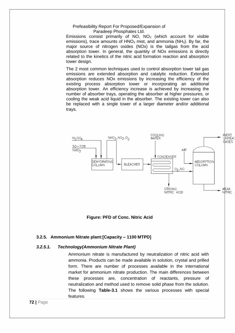
72 | Page
Prefeasibility Report For Proposed/Expansion of Paradeep Phosphates Ltd.
Emissions consist primarily of NO, NO2 (which account for visible emissions), trace amounts of HNO3 mist, and ammonia (NH3). By far, the major source of nitrogen oxides (NOx) is the tailgas from the acid absorption tower. In general, the quantity of NOx emissions is directly related to the kinetics of the nitric acid formation reaction and absorption tower design.
The 2 most common techniques used to control absorption tower tail gas emissions are extended absorption and catalytic reduction. Extended absorption reduces NOx emissions by increasing the efficiency of the existing process absorption tower or incorporating an additional absorption tower. An efficiency increase is achieved by increasing the number of absorber trays, operating the absorber at higher pressures, or cooling the weak acid liquid in the absorber. The existing tower can also be replaced with a single tower of a larger diameter and/or additional
trays.
Figure: PFD of Conc. Nitric Acid
3.2.5. Ammonium Nitrate plant:[Capacity – 1100 MTPD]
3.2.5.1. Technology(Ammonium Nitrate Plant)
Ammonium nitrate is manufactured by neutralization of nitric acid with
ammonia. Products can be made available in solution, crystal and prilled
form. There are number of processes available in the international
market for ammonium nitrate production. The main differences between
these processes are, concentration of reactants, pressure of
neutralization and method used to remove solid phase from the solution.
The following Table-3.1 shows the various processes with special
features.
73 | Page
Prefeasibility Report For Proposed/Expansion of Paradeep Phosphates Ltd.
Table 3.1: Various Processes for Ammonium Nitrate
Name of Process Special Features
Espindesa Process High versatility, different grades can be made.
Mississippi Process Good efficient control prilling.
Fisons Process Low solution hold up of Ammonium Nitrate. Simplicity and ease of control.
ICI Process Neutralization, evaporation, incorporating anti- caking treatment prilling.
Stamicarbon Process Low & high-density products.
NameofProcess SpecialFeatures
Mitshubishi Process High purity,non-caking,adequatehardness,high oil absorption for ANFO.
Sumitomo Process Prilled or crystal form produces High yield, improved product quality by additives.
UHDE Process Low temperature & high concentration in single step.
NorksHydro Process Pressure neutralization, high concentration melts to prilling resulting less water to be removed from drying section, high- density product.
The chemistry and basic process steps followed in all these
processes are essentially same with minor changes in design of
particular equipment or control system. The processes offered by various
licensors are all proven and plants based on these processes are in
operation in various parts of the world.
3.2.5.2. Process Description
The proposed Ammonium Nitrate project is based on Ammonia & Nitric
Acid as a feed stock. Ammonium nitrate is manufactured by
neutralization of nitric acid with ammonia. Products can be made
available in solution, crystal and prilled form. There are number of
processes available in the international market for ammonium nitrate
production. The main differences between these processes are,
concentration of reactants, pressure of neutralization and method used
to remove solid phase from the solution. The process description of
Ammonium Nitrate plant is given in Figure 3.5

74 | Page
Prefeasibility Report For Proposed/Expansion of Paradeep Phosphates Ltd.
The process will be based on neutralization of ammonia and nitric acid in
one stage. The scheme envisages production of low density Ammonium
Nitrate prills. The main sections of the plant are described below:
Vapour Ammonia Superheating
Vapour ammonia will be received from weak Nitric Acid plant at 7.0
kg/cm2 abs pressure and 13oC temperature. It will be superheated to
120oC by steam before feeding to the neutralizer.
Figure 3.5 PFD of Ammonium Nitrate
Neutralization
60% nitric Acid will be directly taken to the Head Tank located within the
plant. Nitric acid from Head Tank will be fed to the Neutralizer. Liquid
entrained in neutralizer vapour will be separated and returned to
Neutralizer. Then the vapour will be scrubbed with acidic liquor to
minimize loss. Recovered liquor will be fed to Neutralizer. The
Neutralized Ammonium Nitrate at about 82% concentration will be taken
to a tank where small amount of ammonia vapour will be bubbled to
make the liquor alkaline.
75 | Page
Prefeasibility Report For Proposed/Expansion of Paradeep Phosphates Ltd.
Neutralization will take place according to the following exothermic
reaction at about 130oC temperature and 1.1 kg/cm2 pressure.
NH3 (g) + HNO3 (1) = NH4 NO3 (1) + 350 kcal/kg
The neutralized liquor will be stored in Evaporator Feed Tank and will be
pumped to the Evaporator Head Tank through a solution filter.
Concentration
The feed liquor and the recycle solution will be concentrated to 97-98%
melt in a single effect natural circulation type evaporator provided with
one steam heated external calendria heater. A pressure of 250 mmHg
will be maintained in Evaporator by a Surface Condenser and Steam
Ejector. The Ammonium Nitrate melt will be taken to Melt Tank via a
filter. A submerged pump will be provided in Melt Tank to pump melt to
Head Tank at the top of the Prilling Tower.
Prilling
Ammonium Nitrate melt will flow by gravity from Prilling Tower Head
Tank to the sprayer provided at the top of the Prilling Tower chamber.
Droplets of the melt will shower down the tower counter-current to an
upward flowing stream of air forced through the tower by centrifugal fans
provided on ground floor. Melt droplets will be cooled by the air stream to
approximately 80oC and formed into small prills with 2 to 3% moisture.
Prills will be collected at the base of the tower over a belt conveyor.
Salt Handling
Wet prills will be conveyed to the Feed Hopper where lumps will be
separated and recycled back. Correct size material from the hopper will
be elevated by a Bucket Elevator and fed to the Dryer. In the Dryer
moistures content in Prills will be reduced to 0.3% (max) by hot air. The
air will be heated by steam in Dryer Air Heater. The dry prills will be
cooled in Cooler with dehumdised air. The prills from cooler will be fed by
a Bucket Elevator to product screen in which oversize and undersize
prills will be separated from the correct size prills. The correct size prills
will be coated with liquid coating agent in Coating Drum.
Bagging
Correct size prills will be taken to the product bunker from the bottom of
the product bunker. The prills will be weighed in 25 kg batches by
weighing cum tipping machine and filled in polythene-lined bags, which
are kept inside hessian bags to provide strength. After heat-sealing the
polythene bags the hessian bags will be separately stitched. The bagged
product will be shifted to the product storage.
76 | Page
Prefeasibility Report For Proposed/Expansion of Paradeep Phosphates Ltd.
Recovery Section
Dust laden air from dryer and cooler will be sucked by exhaust fans and
scrubbed in a Dust Scrubber with dilute Ammonium Nitrate solution. A
circulation pump will be provided to circulate the solution. Condensate
from Surface Condenser will be collected in a tank and pumped to Head
Tank. Condensate from Head Tank will be fed to the top of Neutralizer
Scrubber and the suction side of the Dust Scrubber Circulation Pump for
make up. Overflow from the Dust Scrubber bottom and recovered liquor
from Neutralizer Scrubber will be taken to the Dissolution Tank.
Lumps from the Feed Hoper will be shifted by a Wheel Burrow. Oversize
and undersize prills will be directly discharged from the Product Screen.
All the recycle Ammonium Nitrate will be taken to the Dissolution Tank
where these will be dissolved in dilute solution coming from the
Dust Scrubber. The recycle solution will be transferred to Evaporator by
Recycle Solution Pump through Solution Filter and Head Tank.
77 | Page
Prefeasibility Report For Proposed/Expansion of Paradeep Phosphates Ltd.
3.2.6. DAP PLANT: [Capacity – 1300 MTPD]
3.2.6.1. Technology
The proposed fertilizer complex shall have the facilities for the production
of Di- ammonium phosphate (DAP) as finished product with raw
materials Sulphuric acid, Phosphoric acid and Ammonia being supplied
along with all required offsites and utility facilities at the plant battery
limit. The process descriptions of the main and intermediate plants are
discussed below in Figure 3.6
3.2.6.2. Chemistry of the Process
Di ammonium phosphate (DAP) is formed when phosphoric acid reacts
with two moles of ammonia.
H3PO4+ 2NH3 → (NH4)2HPO4 The above reaction is exothermic.
3.2.6.3. Plant Description
Raw materials Dosing system
Solid raw material fed to the process plant is mainly filler viz. sweet river
sand or ETP sludge,-spec material is also transferred from off spec/filler
storage to process plant.
Filler material is charged either manually or by pay loaders into the
offspec/filler hopper placed over inlet chute of offspec/Filler bucket
elevator Filler/offspec will be fed to this elevator uniformly by vibratory
feeder.
Slurry Preparation
The process is based on the operation of single pipe reactor fitted within
the granulator, operating on gas Ammonia. Ammonia is supplied from
Ammonia transfer pumps from Ammonia storage tanks to pipe reactors.
The required N/P ratio is finally reached in the granulator by
injection of additional liquid Ammonia into the solids bed through a
ploughshare ammoniation system.
The production of DAP shall be controlled by flow controlling of ammonia
and phosphoric acid in the pipe reactor accurately through ratio control.
The N:P ratio is controlled within the range of 1.8 to 2.
78 | Page
Prefeasibility Report For Proposed/Expansion of Paradeep Phosphates Ltd.
The pipe reactor installation facilitates the slurry of Ammonium
phosphate and small amount of sulphate formed by neutralization
reaction inside pipe reactor to be sprayed directly onto the solids bed of
the granulator this pipe reactor (P.R.) slurry have temperatures ranging
from 135 to 150oC and moisture content between 4 and 8%.
Phosphoric acid fed to pipe reactor is made by the acid coming from the scrubbing system, complemented by the concentrated acid fed to pipe reactor vessel plus, occasionally, some process water.
Granulation
To make DAP, all the raw materials and recirculated solids will be fed to
the granulator. Recycle flow put normally an upper limit in the solids
capacity of the plant. The recycle is constituted by fines, crushed
oversize and part of the commercial product, which is returned to the
granulator to keep the water and heat balance.
Granulator is equipped with a lump kicker to prevent any lump from
remaining inside the drum disturbing the flow of solids and avoiding their
normal flow in the dryer. Lumps kicker will reject the lumps to an
attached grizzly, which will disintegrate them by the rotating action.
Solids leaving granulator, normally with moisture content around 1.8-
2.4% are gravity fed to dryer, in order to achieve the final guaranteed
moisture of 1.0%.
Gases emitted in the granulator are sucked towards the Granulator Pre-
scrubber to recover most of the evolved dust and ammonia.

79 | Page
Prefeasibility Report For Proposed/Expansion of Paradeep Phosphates Ltd.
Figure 3.6: PFD of DAP
Product Drying, Screening and Grinding
In the Rotary Drum Dryer, the moisture in the solids coming from
granulator is reduced with a preheated air in a co-current flow.
Dryer drum exit is equipped with a grizzly, to avoid any lump, which
could block the dryer elevator. If any lump is coming out, grizzly takes it
up and throws it into a hopper, which feeds the lump crusher. Crushed
lumps will join the rest of dryer discharged product on exist dryer belt
conveyor. Air leaving the dryer contains some Ammonia escaped from
the product as well as dust and water evaporated from product when
drying.

80 | Page
Prefeasibility Report For Proposed/Expansion of Paradeep Phosphates Ltd.
Cyclones separators are used to separate the carried dust and the
air is subsequently scrubbed to get free from ammonia.
Dried product is fed to the process screens. The on-size product from
screen passes directly to a recycle regulator. The separated over-
sizes fall by gravity into oversize mills.
Undersize product from screen falls by gravity to the recycle belt
conveyor.
Air Desaturation Unit
The purpose of the Air De-saturation Unit is to chill air to low temperature
to reduce moisture content and to heat the outgoing air from the chilling
unit to reduce the relative humidity of the air going to the Rotary Cooler.
This is required to prevent moisture pick up by outgoing product from the
ambient air provided for cooling.
Final Product Treatment
On-size product is cooled down using conditioned air from the
Desaturation unit. DAP having critical relativity humidity (CRH) of about
75% at 30oC, the product DAP picks up moisture if the ambient air has a
higher relative moisture. Air heater increases air temperature and
consequently decreases air relative humidity.
Dust coming out with the air leaving the cooler and plant dedusting
system is recovered and fed back to the recycle conveyor. Cooled
product is fed to the final product belt conveyor.
Gas Scrubbing
The gas scrubbing is carried out in several washing steps e.g. in a
granulator pre- scrubber, dryer scrubber, Granulator scrubber, Cooler
and dedusting scrubber and final tail gas scrubber, where the streams
leaving the mentioned three scrubbers will be washed.
The gases leaving Dryer scrubber together with the gases from the
granulator scrubber and Cooler & Dedusting scrubber are fed to the Tail
gas scrubber. Scrubber exhaust gases will be cleaned with acidulated
water to reduce its dust, fluorine and ammonia content. To achieve this,
the scrubber liquor is slightly acidulated with sulphuric acid in order to
absorb both Ammonia and Fluorine. Process water is used as a washing
liquid in the scrubber.
Defoamer is used in the scrubbers and vessels where phosphoric acid is
used to prevent the formation of foams.
81 | Page
Prefeasibility Report For Proposed/Expansion of Paradeep Phosphates Ltd.
3.2.7. GSSP PLANT: [Capacity – 1650 MTPD]
3.2.7.1. Technology
The unit operation of SSP production is a very simple. The process
involves rock phosphate grinding and mixing with sulfuric acid. No
process license etc. is required to be obtained from any process licensor.
It has been considered that the proposed plant shall achieve 300 days of
operation at 100% capacity utilization. This requirement is vital for
profitability as well. This can be achieved only through robust plant
design, equipment selection, reliable equipment fabricator and a
competent plant designer with proven capabilities.
3.2.7.2. The Chemistry
Single super phosphate is produced in a twosteps process.
2Ca5(PO4)3F+7H2SO4+3H2O → 7CaSO4+3Ca(H2PO4)2.H2O +2HF
Step1 -Phosphate rock blending andgrinding
The phosphate rock is ground until at least 75% is less than 75 µm
(microns) in diameter, and then analysed for composition. The
proportions of various rock varieties are blended to give the desired
composition.
Step2 – Superphosphate manufacture
Ground Phosphate rock, sulfuric acid and water are mixed and then
allowed to dry and react to give the superphosphate - a mixture of
CaSO4 and Ca(H2PO4)2.H2O.
The SSP manufacturing process will comprise of two basic steps: The
basic reaction in the manufacture of superphosphate is the reaction
of insoluble phosphate rock with Sulfuric Acid to form the soluble
Calcium di- Hydrogen Phosphate, Ca(H2PO4)2.
This is described by the following equation:
(PO4)-3
+H2SO4→ H2PO4-+ (SO4)-2
The phosphate rock imported from various sources, is mainly
fluorapatite, (Ca5 (PO4)3F). The actual composition of the phosphate
rock varies with the source. The reactions occurring during the
production of superphosphate are complex and are usually summarised
as follows:
Ca5 (PO4)3F + 5H2SO4 → 5CaSO4 + 3H3PO4 + HF
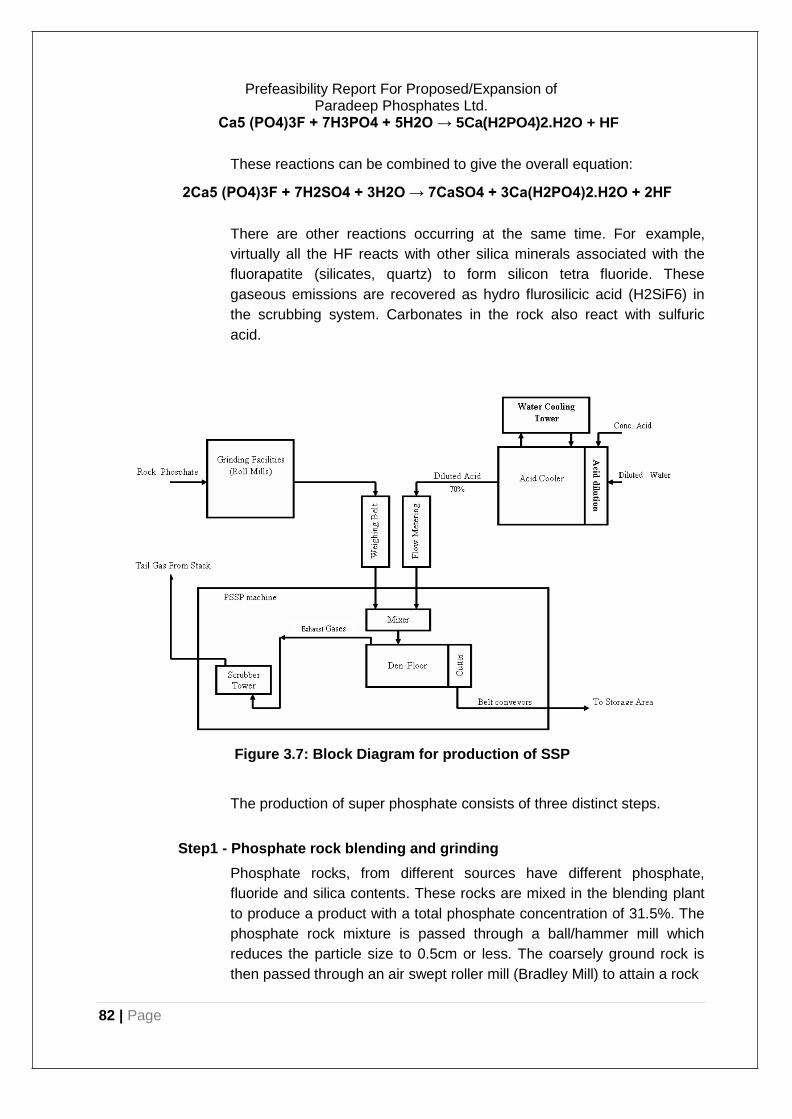
82 | Page
Prefeasibility Report For Proposed/Expansion of Paradeep Phosphates Ltd.
Ca5 (PO4)3F + 7H3PO4 + 5H2O → 5Ca(H2PO4)2.H2O + HF
These reactions can be combined to give the overall equation:
2Ca5 (PO4)3F + 7H2SO4 + 3H2O → 7CaSO4 + 3Ca(H2PO4)2.H2O + 2HF
There are other reactions occurring at the same time. For example,
virtually all the HF reacts with other silica minerals associated with the
fluorapatite (silicates, quartz) to form silicon tetra fluoride. These
gaseous emissions are recovered as hydro flurosilicic acid (H2SiF6) in
the scrubbing system. Carbonates in the rock also react with sulfuric
acid.
Figure 3.7: Block Diagram for production of SSP
The production of super phosphate consists of three distinct steps.
Step1 - Phosphate rock blending and grinding
Phosphate rocks, from different sources have different phosphate,
fluoride and silica contents. These rocks are mixed in the blending plant
to produce a product with a total phosphate concentration of 31.5%. The
phosphate rock mixture is passed through a ball/hammer mill which
reduces the particle size to 0.5cm or less. The coarsely ground rock is
then passed through an air swept roller mill (Bradley Mill) to attain a rock
83 | Page
Prefeasibility Report For Proposed/Expansion of Paradeep Phosphates Ltd.
grist of approximately 75% less than 75 microns. The powdered rock is
stored in a large hopper. The powder handling system is fitted with a
dust collection system.
Fine Phosphate is transported to ground Phosphate Hopper to be used
for PSSP production. Dilution and Cooling Systems are used to Dilute
the concentrated Sulphuric Acid 98.5% to 70% concentration, and to cool
down the produced Diluted Acid (178°C), because the Dilution
Process is exothermic. Dilution Process (as a result of mixing water
with Conc. Acid) and cooling system is sophisticated systems due to the
highly corrosive effect of the Diluted Acid. For that, all parts in contact
with Diluted Acid made from special Graphite can bear the operating
conditions such as: Diluted acid inlet Temperature: 178 °C Pressure
inside the cooler: > 2 bars
This system is fully automated and provides all the safety precautions
necessary to guarantee safe operation not only for operators but also for
the Graphite Cooler and cable to control the outlet concentration and
temperature. The Diluted Acid (DSA) is stored in Storage Tank lined with
Rubber and acid bricks. The cooling water necessary to cool the DSA is
re-circulated in water Cooling Tower to minimize the consumed water
and in turn the waste water.
Step2 –Super phosphate manufacture
Ground Phosphate is sent to the PSSP production plant using suitable
material handling equipments such as completely sealed Screw
Conveyors, Bucket Elevators etc. Diluted Acid is pumped to PSSP
production plant using special chemical pumps. PSSP plant is designed
to use 70% Sulphuric Acid, recycled scrubber liquor and ground
phosphate rock. It is based on the most technically and economically up
to date feasible process and is compatible with Environment Protection
Requirements
Feed Metering is achieved with Automatic Control System. The ground
rock and sulfuric acid are reacted in a horizontal mixer. A continuous flow
of the sloppy mix drops out of the mixer into the Broad field Den. Broad
Field Mixer developed specially for PSSP manufacture is a large two
stage horizontal paddle mixer, the two stage design ensures complete
mixing and good chemical reaction (quality) of SSP powder. Varying
speed drive and adjustable paddle configuration allows selection of
optimum mixing conditions for all phosphate rocks with Acid.
The den consists of a slowly moving floor (approx. 300 mm/min), built
from steel tee slats, with polypropylene sealing strips, to prevent
leakage, to enable setting of the cake and reciprocating sides, lined with
cement fondu (special tile) and are driven by two geared motor units
through two heavy crank arms which prevent the superphosphate
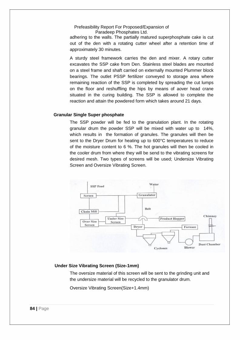
84 | Page
Prefeasibility Report For Proposed/Expansion of Paradeep Phosphates Ltd.
adhering to the walls. The partially matured superphosphate cake is cut
out of the den with a rotating cutter wheel after a retention time of
approximately 30 minutes.
A sturdy steel framework carries the den and mixer. A rotary cutter
excavates the SSP cake from Den. Stainless steel blades are mounted
on a steel frame and shaft carried on externally mounted Plummer block
bearings. The outlet PSSP fertilizer conveyed to storage area where
remaining reaction of the SSP is completed by spreading the cut lumps
on the floor and reshuffling the hips by means of aover head crane
situated in the curing building. The SSP is allowed to complete the
reaction and attain the powdered form which takes around 21 days.
Granular Single Super phosphate
The SSP powder will be fed to the granulation plant. In the rotating
granular drum the powder SSP will be mixed with water up to 14%,
which results in the formation of granules. The granules will then be
sent to the Dryer Drum for heating up to 600°C temperatures to reduce
of the moisture content to 6 %. The hot granules will then be cooled in
the cooler drum from where they will be send to the vibrating screens for
desired mesh. Two types of screens will be used; Undersize Vibrating
Screen and Oversize Vibrating Screen.
Under Size Vibrating Screen (Size-1mm)
The oversize material of this screen will be sent to the grinding unit and
the undersize material will be recycled to the granulator drum.
Oversize Vibrating Screen(Size+1.4mm)
85 | Page
Prefeasibility Report For Proposed/Expansion of Paradeep Phosphates Ltd.
The oversize material of this screen will be sent to the crusher from
where it will be taken to the granulator drum. The properly sized material
will be packed in 50kg HDPE Bags.
SSP dust evolved in the process of granulation will be scrubbed with the
help of twin cyclone system through blower provided for dryer drum and
the clean air will then be discharged through a stack of 30 m height.
The grinding of rock phosphate may lead to emissions of dust. Pulse jet
dust collector will be provided to control dust emissions. A stack will be
provided at the ball mill. At mixer and Den, during acidulation, gases will
be liberated. These gases from mixer and Den will be passed through
absorption stages as under;
a) Ejector b) Cyclone separator c) Venturi Scrubber d) Multi Stage Scrubbing Towers
Fresh water or effluent water will be charged in to sumps of the ejector,
Cyclone separator, Venturi and scrubbing towers on the day to day
basis. After utilization of water in the circulation for gas scrubbing
system, the dilute acid (H2SiF6) will be taken from all the circulation
sumps to a common thickener sump every day. The ejector, Venturi
and separator will scrub the gases and gases will go further to blower
and will be discharged through stack of 30 meter height where the wind
velocity is high and thus get further diluted.
The effluent will be collected in a common sump along with silica. This
silica will settle down and will be used as filler material for SSP. The
dilute acid (H2SiF6) will be discharged in to the same sump and will be
reused for acid dilution in SSP Process. Thus a Zero Discharge system
will be achieved.
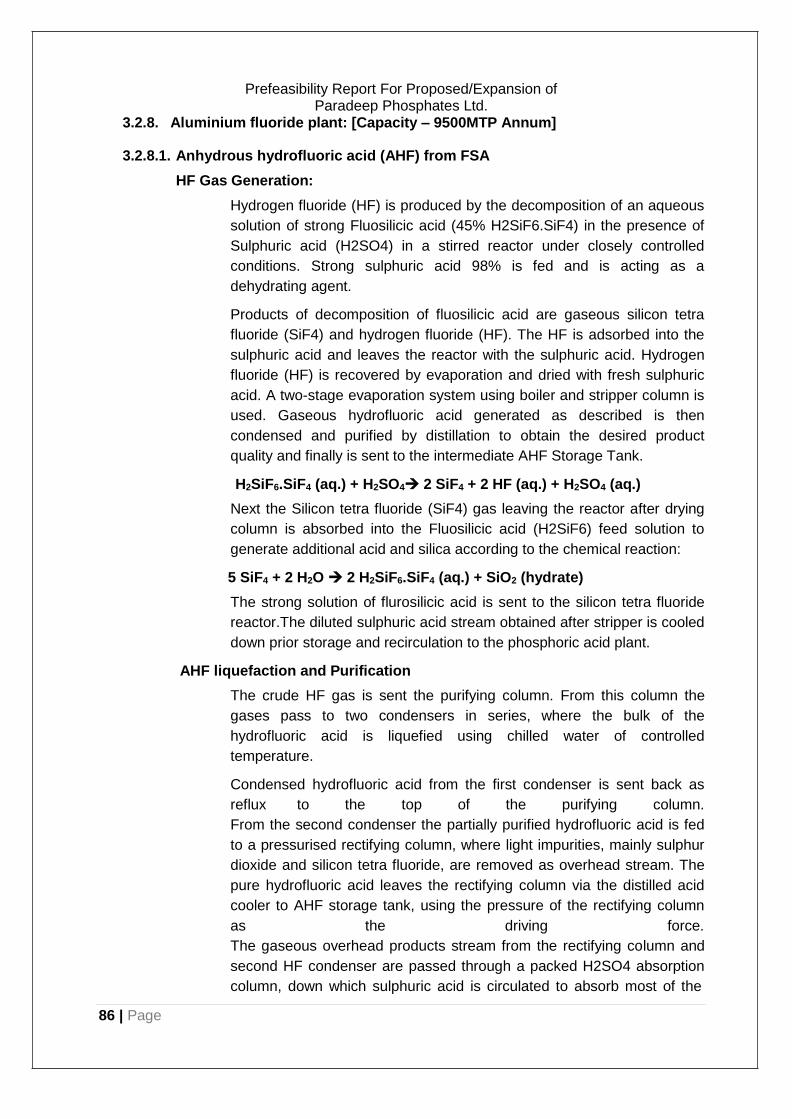
86 | Page
Prefeasibility Report For Proposed/Expansion of Paradeep Phosphates Ltd.
3.2.8. Aluminium fluoride plant: [Capacity – 9500MTP Annum]
3.2.8.1. Anhydrous hydrofluoric acid (AHF) from FSA
HF Gas Generation:
Hydrogen fluoride (HF) is produced by the decomposition of an aqueous
solution of strong Fluosilicic acid (45% H2SiF6.SiF4) in the presence of
Sulphuric acid (H2SO4) in a stirred reactor under closely controlled
conditions. Strong sulphuric acid 98% is fed and is acting as a
dehydrating agent.
Products of decomposition of fluosilicic acid are gaseous silicon tetra
fluoride (SiF4) and hydrogen fluoride (HF). The HF is adsorbed into the
sulphuric acid and leaves the reactor with the sulphuric acid. Hydrogen
fluoride (HF) is recovered by evaporation and dried with fresh sulphuric
acid. A two-stage evaporation system using boiler and stripper column is
used. Gaseous hydrofluoric acid generated as described is then
condensed and purified by distillation to obtain the desired product
quality and finally is sent to the intermediate AHF Storage Tank.
H2SiF6.SiF4 (aq.) + H2SO4 2 SiF4 + 2 HF (aq.) + H2SO4 (aq.)
Next the Silicon tetra fluoride (SiF4) gas leaving the reactor after drying
column is absorbed into the Fluosilicic acid (H2SiF6) feed solution to
generate additional acid and silica according to the chemical reaction:
5 SiF4 + 2 H2O 2 H2SiF6.SiF4 (aq.) + SiO2 (hydrate)
The strong solution of flurosilicic acid is sent to the silicon tetra fluoride
reactor.The diluted sulphuric acid stream obtained after stripper is cooled
down prior storage and recirculation to the phosphoric acid plant.
AHF liquefaction and Purification
The crude HF gas is sent the purifying column. From this column the
gases pass to two condensers in series, where the bulk of the
hydrofluoric acid is liquefied using chilled water of controlled
temperature.
Condensed hydrofluoric acid from the first condenser is sent back as
reflux to the top of the purifying column.
From the second condenser the partially purified hydrofluoric acid is fed
to a pressurised rectifying column, where light impurities, mainly sulphur
dioxide and silicon tetra fluoride, are removed as overhead stream. The
pure hydrofluoric acid leaves the rectifying column via the distilled acid
cooler to AHF storage tank, using the pressure of the rectifying column
as the driving force.
The gaseous overhead products stream from the rectifying column and
second HF condenser are passed through a packed H2SO4 absorption
column, down which sulphuric acid is circulated to absorb most of the
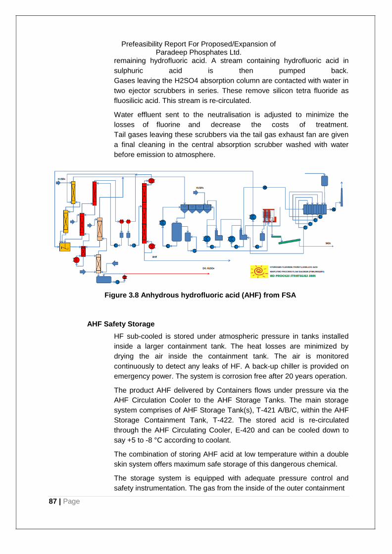
Prefeasibility Report For Proposed/Expansion of Paradeep Phosphates Ltd.
remaining hydrofluoric acid. A stream containing hydrofluoric acid in
sulphuric acid is then pumped back.
Gases leaving the H2SO4 absorption column are contacted with water in
two ejector scrubbers in series. These remove silicon tetra fluoride as
fluosilicic acid. This stream is re-circulated.
Water effluent sent to the neutralisation is adjusted to minimize the
losses of fluorine and decrease the costs of treatment.
Tail gases leaving these scrubbers via the tail gas exhaust fan are given
a final cleaning in the central absorption scrubber washed with water
before emission to atmosphere.
Figure 3.8 Anhydrous hydrofluoric acid (AHF) from FSA
AHF Safety Storage
HF sub-cooled is stored under atmospheric pressure in tanks installed
inside a larger containment tank. The heat losses are minimized by
drying the air inside the containment tank. The air is monitored
continuously to detect any leaks of HF. A back-up chiller is provided on
emergency power. The system is corrosion free after 20 years operation.
The product AHF delivered by Containers flows under pressure via the
AHF Circulation Cooler to the AHF Storage Tanks. The main storage
system comprises of AHF Storage Tank(s), T-421 A/B/C, within the AHF
Storage Containment Tank, T-422. The stored acid is re-circulated
through the AHF Circulating Cooler, E-420 and can be cooled down to
say +5 to -8 °C according to coolant.
The combination of storing AHF acid at low temperature within a double
skin system offers maximum safe storage of this dangerous chemical.
The storage system is equipped with adequate pressure control and
safety instrumentation. The gas from the inside of the outer containment
87 | Page
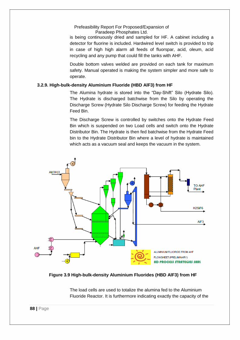
88 | Page
Prefeasibility Report For Proposed/Expansion of Paradeep Phosphates Ltd.
is being continuously dried and sampled for HF. A cabinet including a
detector for fluorine is included. Hardwired level switch is provided to trip
in case of high high alarm all feeds of fluorspar, acid, oleum, acid
recycling and any pump that could fill the tanks with AHF.
Double bottom valves welded are provided on each tank for maximum
safety. Manual operated is making the system simpler and more safe to
operate.
3.2.9. High-bulk-density Aluminium Fluoride (HBD AlF3) from HF
The Alumina hydrate is stored into the “Day-Shift” Silo (Hydrate Silo).
The Hydrate is discharged batchwise from the Silo by operating the
Discharge Screw (Hydrate Silo Discharge Screw) for feeding the Hydrate
Feed Bin.
The Discharge Screw is controlled by switches onto the Hydrate Feed
Bin which is suspended on two Load cells and switch onto the Hydrate
Distributor Bin. The Hydrate is then fed batchwise from the Hydrate Feed
bin to the Hydrate Distributor Bin where a level of hydrate is maintained
which acts as a vacuum seal and keeps the vacuum in the system.
Figure 3.9 High-bulk-density Aluminium Fluorides (HBD AlF3) from HF
The load cells are used to totalize the alumina fed to the Aluminium
Fluoride Reactor. It is furthermore indicating exactly the capacity of the
89 | Page
Prefeasibility Report For Proposed/Expansion of Paradeep Phosphates Ltd.
Aluminium Fluoride Reactor. The alumina tri-hydrate is fed continuously
to the Reactor via two Feed Screws.
First Hydrate Feed Screw is feeding most of the material and is
controlling the temperature in the top bed. The speed of the Hydrate
Feed Screw is adjusted according to the temperature in the bottom bed
and top bed.
The Feed Screw is feeding the material via a fluidisation cup and this for
avoiding the agglomeration of hydrate especially at start-up. Hydrate
Bottom Feed Screw feeds the bottom bed at a small feed rate for diluting
the bottom bed and for obtaining a lower grade for the aluminium fluoride
product. This is controlled manually by setting the speed of this screw
manually.
The reaction can be represented by the following equations:
Al2O3.3H2O Al2O3 + 3 H2O
Al2O3 + 6 HF 2 AlF3 + 3 H2O
Since the overall reaction is exothermic, the AlF3 Reactor does not need
supplementary heat during normal operation. During start-up it does
need to be preheated using the Combustion Chamber. This item is also
used for keeping warm the aluminium fluoride Reactor if the feed of HF
gas is interrupted.
Solids carried out of the Reactor are recovered by cyclone separators.
Under rated capacity, the dust collected in cyclone 1 is not re-circulated
to the Aluminium Fluoride Reactor. Only under high load or if the quality
needs to be improved dusts are re-circulated to the aluminium fluoride
reactor preferably to the top bed if the grade has to be increased and
preferably to the bottom bed if both the grade has to be improved and
the content of silica to be reduced significantly. Whether or not dusts are
re-circulated to the Aluminium Fluoride Reactor, the discharge of dusts
from Cyclone directly to product into the Aluminium Fluoride Cooler, is
always operated.
Vacuum is kept at discharges of cyclones by level maintained in Cyclone
Bin installed underneath and equipped with discharge device and valve.
The aluminium fluoride is discharged from the bottom bed of the
Aluminium Fluoride Reactor through the discharge and then cooled down
into a fluidised bed cooler to a temperature preferably lower than 80°C.
The Off-gases from aluminium fluoride reactor after Cyclones are
quenched and condensed in the absorber and then are scrubbed.
The condensation of HF, H2O, etc occurs in the Absorber and HF
Scrubber without addition of water. The concentration of fluorine in the

90 | Page
Prefeasibility Report For Proposed/Expansion of Paradeep Phosphates Ltd.
liquor formed provides a good indication of the efficiency of the reactor
and is used for its control.
The diluted acid solution produced will be sent to the neutralization plant
or reused.The second column is used to remove the traces of Fluorine,
S, dusts, etc. This column is the stand-by unit for the third column in
case of fouling and vice versa.
The fluidisation in the Aluminium Fluoride Reactor is maintained by the
vacuum obtained from the operation of a Steam Ejector. An Absorption
System common to the aluminium fluoride plant and hydrofluoric acid is
provided Water is sent to the final absorber in order to absorb totally HF
and reach the emission limit for F in the off-gases in all modes of
operation of the plant. This effluent water is also sent to the
neutralization plant or reused.
3.3. Raw Material
3.3.1. Ammonia/gasification:
Raw material Consumption for 2200 TPD Ammonia: SES BASED. SL. No. Input Requirement UOM
1. Coal/petcoke 5,633 TPD
2. Oxygen 70,000 Kg/Hr
3. Power 70,553 KW
4. Cooling Water 17,582 TPH
5. BFW-(HP+LP) 431 (227.9+203.1) TPH
6. Raw Water 800 TPH
7. Service Water 425 TPH
8. DM Water 273 TPH
9. Portable Water 13.6 TPH
10. Instrumental Air 2,038 Nm3/Hr
11. Plant Air 510 Nm3/Hr
12. LP Nitrogen 43 Nm3/Hr
13. HP Nitrogen 82,237 Nm3/Hr
14. Diesel 0.8 M3/Hr
15. Fuel Gas 11,703 Nm3/Hr
16. Steam-(LP+MP+HP) (645.8)1.8+421+223 TPH
17. Condensate-(LP+MP) 33 (2+31)
3.3.2. Urea plant:
Sl. No.
RawMaterial/Utilities Unit(hourly) Requirement
1.0 Ammonia MT 91.67
2.0 CO2 MT 118.7
3.0 HP Steam MT 126
4.0 MP Steam MT 21
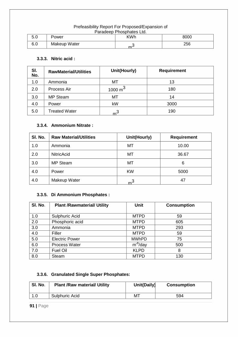
91 | Page
Prefeasibility Report For Proposed/Expansion of Paradeep Phosphates Ltd.
5.0 Power KWh 8000
6.0 Makeup Water m3 256
3.3.3. Nitric acid :
Sl. No.
RawMaterial/Utilities Unit(Hourly) Requirement
1.0 Ammonia MT 13
2.0 Process Air 1000 m3 180
3.0 MP Steam MT 14
4.0 Power kW 3000
5.0 Treated Water m3 190
3.3.4. Ammonium Nitrate :
Sl. No. Raw Material/Utilities Unit(Hourly) Requirement
1.0 Ammonia MT 10.00
2.0 NitricAcid MT 36.67
3.0 MP Steam MT 6
4.0 Power KW 5000
4.0 Makeup Water m3 47
3.3.5. Di Ammonium Phosphates :
Sl. No. Plant /Rawmaterial/ Utility Unit Consumption
1.0 Sulphuric Acid MTPD 59
2.0 Phosphoric acid MTPD 605
3.0 Ammonia MTPD 293
4.0 Filler MTPD 59
5.0 Electric Power MWhPD 75
6.0 Process Water m3/day 500
7.0 Fuel Oil KLPD 8
8.0 Steam MTPD 130
3.3.6. Granulated Single Super Phosphates:
Sl. No. Plant /Raw material/ Utility Unit(Daily) Consumption
1.0 Sulphuric Acid MT 594
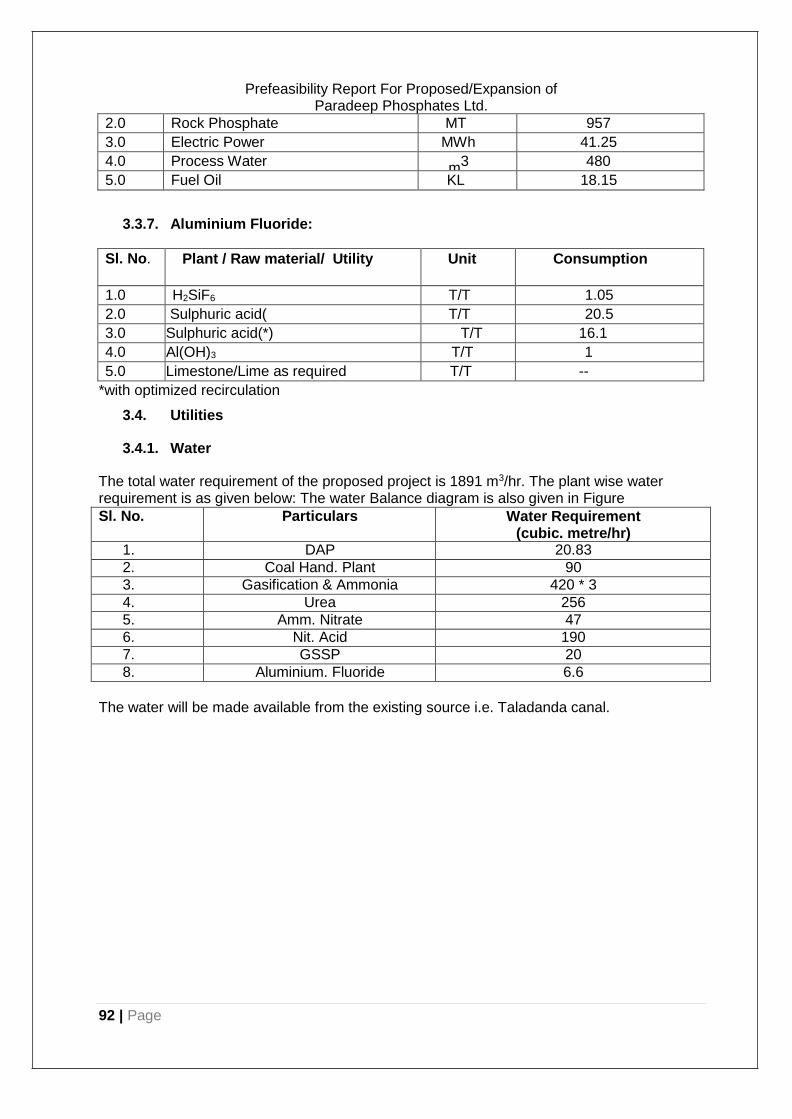
92 | Page
Prefeasibility Report For Proposed/Expansion of Paradeep Phosphates Ltd.
2.0 Rock Phosphate MT 957
3.0 Electric Power MWh 41.25
4.0 Process Water m3 480
5.0 Fuel Oil KL 18.15
3.3.7. Aluminium Fluoride:
Sl. No. Plant / Raw material/ Utility Unit Consumption
1.0 H2SiF6 T/T 1.05
2.0 Sulphuric acid( T/T 20.5
3.0 Sulphuric acid(*) T/T 16.1
4.0 Al(OH)3 T/T 1
5.0 Limestone/Lime as required T/T --
*with optimized recirculation
3.4. Utilities
3.4.1. Water
The total water requirement of the proposed project is 1891 m3/hr. The plant wise water requirement is as given below: The water Balance diagram is also given in Figure
Sl. No. Particulars Water Requirement (cubic. metre/hr)
1. DAP 20.83
2. Coal Hand. Plant 90
3. Gasification & Ammonia 420 * 3
4. Urea 256
5. Amm. Nitrate 47
6. Nit. Acid 190
7. GSSP 20
8. Aluminium. Fluoride 6.6
The water will be made available from the existing source i.e. Taladanda canal.
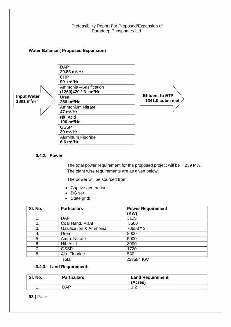
93 | Page
Prefeasibility Report For Proposed/Expansion of Paradeep Phosphates Ltd.
Water Balance ( Proposed Expansion)
3.4.2. Power
The total power requirement for the proposed project will be ~ 239 MW.
The plant wise requirements are as given below:
The power will be sourced from:
• Captive generation---
• DG set
• State grid:
Sl. No. Particulars Power Requirement (KW)
1. DAP 3125
2. Coal Hand. Plant 5500
3. Gasification & Ammonia 70553 * 3
4. Urea 8000
5. Amm. Nitrate 5000
6. Nit. Acid 3000
7. GSSP 1720
8. Alu. Fluoride 580
Total 238584 KW
3.4.3. Land Requirement:
Sl. No. Particulars Land Requirement
(Acres) 1. DAP 1.2
DAP 20.83 m3/Hr
CHP 90 m3/Hr
Ammonia –Gasification (1260)420 * 3 m3/Hr
Urea 256 m3/Hr
Ammonium Nitrate 47 m3/Hr
Nit. Acid 190 m3/Hr
GSSP 20 m3/Hr
Aluminum Fluoride 6.6 m3/Hr
Input Water 1891 m3/Hr
Effluent to ETP
1341.0 cubic met
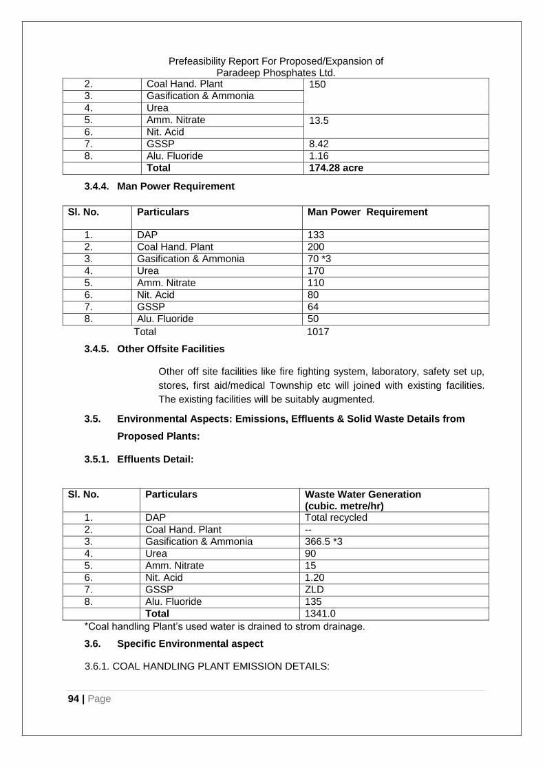
94 | Page
Prefeasibility Report For Proposed/Expansion of Paradeep Phosphates Ltd.
2. Coal Hand. Plant 150 3. Gasification & Ammonia
4. Urea
5. Amm. Nitrate 13.5 6. Nit. Acid
7. GSSP 8.42
8. Alu. Fluoride 1.16 Total 174.28 acre
3.4.4. Man Power Requirement
Sl. No. Particulars Man Power Requirement
1. DAP 133
2. Coal Hand. Plant 200
3. Gasification & Ammonia 70 *3
4. Urea 170
5. Amm. Nitrate 110
6. Nit. Acid 80
7. GSSP 64
8. Alu. Fluoride 50
Total 1017
3.4.5. Other Offsite Facilities
Other off site facilities like fire fighting system, laboratory, safety set up,
stores, first aid/medical Township etc will joined with existing facilities.
The existing facilities will be suitably augmented.
3.5. Environmental Aspects: Emissions, Effluents & Solid Waste Details from
Proposed Plants:
3.5.1. Effluents Detail:
Sl. No. Particulars Waste Water Generation
(cubic. metre/hr) 1. DAP Total recycled
2. Coal Hand. Plant --
3. Gasification & Ammonia 366.5 *3
4. Urea 90
5. Amm. Nitrate 15
6. Nit. Acid 1.20
7. GSSP ZLD
8. Alu. Fluoride 135 Total 1341.0
*Coal handling Plant’s used water is drained to strom drainage.
3.6. Specific Environmental aspect
3.6.1. COAL HANDLING PLANT EMISSION DETAILS:
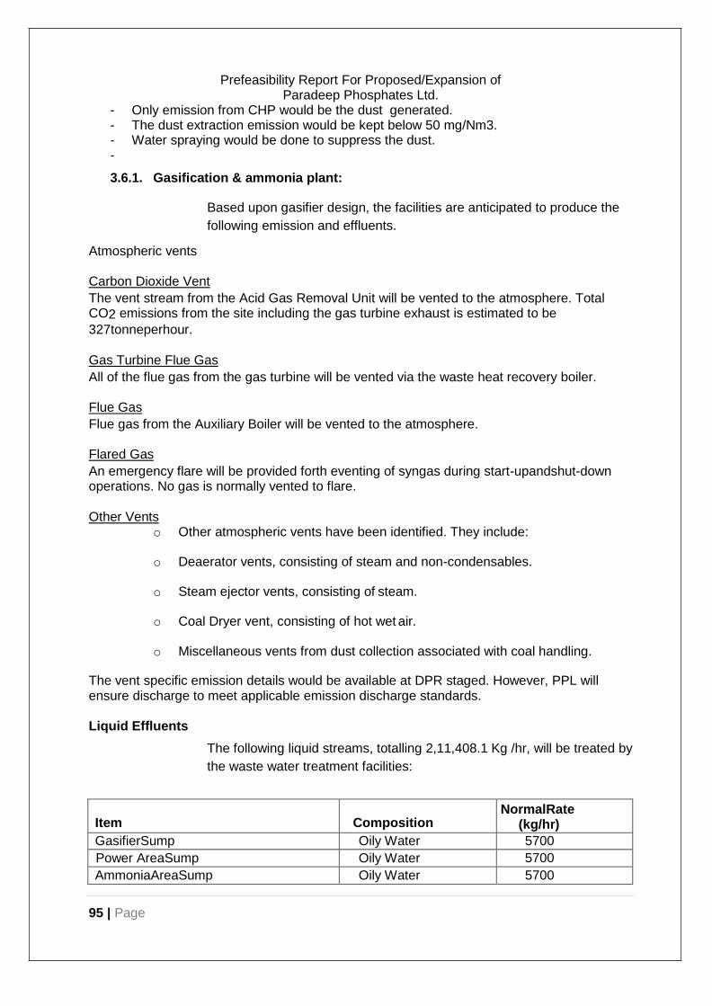
95 | Page
Prefeasibility Report For Proposed/Expansion of Paradeep Phosphates Ltd.
- Only emission from CHP would be the dust generated. - The dust extraction emission would be kept below 50 mg/Nm3. - Water spraying would be done to suppress the dust. -
3.6.1. Gasification & ammonia plant:
Atmospheric vents
Based upon gasifier design, the facilities are anticipated to produce the
following emission and effluents.
Carbon Dioxide Vent
The vent stream from the Acid Gas Removal Unit will be vented to the atmosphere. Total CO2 emissions from the site including the gas turbine exhaust is estimated to be
327tonneperhour.
Gas Turbine Flue Gas
All of the flue gas from the gas turbine will be vented via the waste heat recovery boiler.
Flue Gas
Flue gas from the Auxiliary Boiler will be vented to the atmosphere.
Flared Gas
An emergency flare will be provided forth eventing of syngas during start-upandshut-down operations. No gas is normally vented to flare.
Other Vents
o Other atmospheric vents have been identified. They include:
o Deaerator vents, consisting of steam and non-condensables.
o Steam ejector vents, consisting of steam.
o Coal Dryer vent, consisting of hot wet air.
o Miscellaneous vents from dust collection associated with coal handling.
The vent specific emission details would be available at DPR staged. However, PPL will ensure discharge to meet applicable emission discharge standards.
Liquid Effluents
The following liquid streams, totalling 2,11,408.1 Kg /hr, will be treated by
the waste water treatment facilities:
Item
Composition
NormalRate (kg/hr)
GasifierSump Oily Water 5700
Power AreaSump Oily Water 5700
AmmoniaAreaSump Oily Water 5700
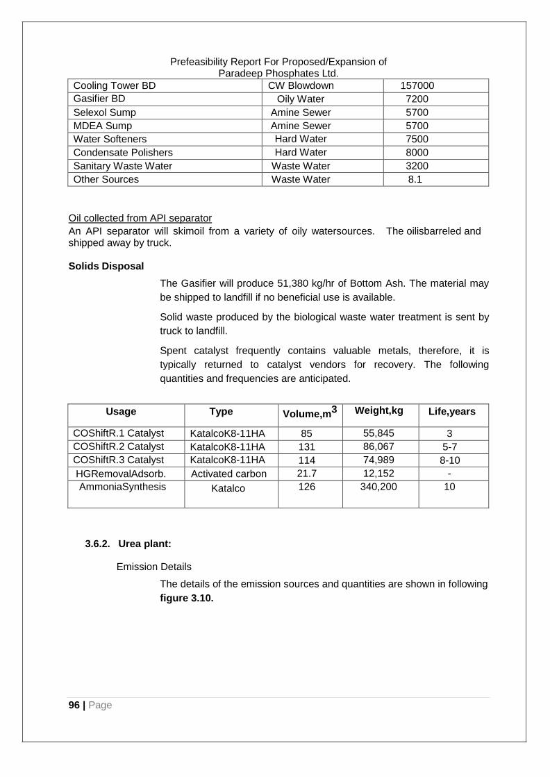
96 | Page
Prefeasibility Report For Proposed/Expansion of Paradeep Phosphates Ltd.
Cooling Tower BD CW Blowdown 157000
Gasifier BD Oily Water 7200
Selexol Sump Amine Sewer 5700
MDEA Sump Amine Sewer 5700
Water Softeners Hard Water 7500
Condensate Polishers Hard Water 8000
Sanitary Waste Water Waste Water 3200
Other Sources Waste Water 8.1
Oil collected from API separator
An API separator will skimoil from a variety of oily watersources. The oilisbarreled and shipped away by truck.
Solids Disposal
The Gasifier will produce 51,380 kg/hr of Bottom Ash. The material may
be shipped to landfill if no beneficial use is available.
Solid waste produced by the biological waste water treatment is sent by
truck to landfill.
Spent catalyst frequently contains valuable metals, therefore, it is
typically returned to catalyst vendors for recovery. The following
quantities and frequencies are anticipated.
Usage Type Volume,m3 Weight,kg Life,years
COShiftR.1 Catalyst KatalcoK8-11HA 85 55,845 3
COShiftR.2 Catalyst KatalcoK8-11HA 131 86,067 5-7
COShiftR.3 Catalyst KatalcoK8-11HA 114 74,989 8-10
HGRemovalAdsorb. Activated carbon 21.7 12,152 -
AmmoniaSynthesis Katalco 126 340,200 10
3.6.2. Urea plant:
Emission Details
The details of the emission sources and quantities are shown in following
figure 3.10.
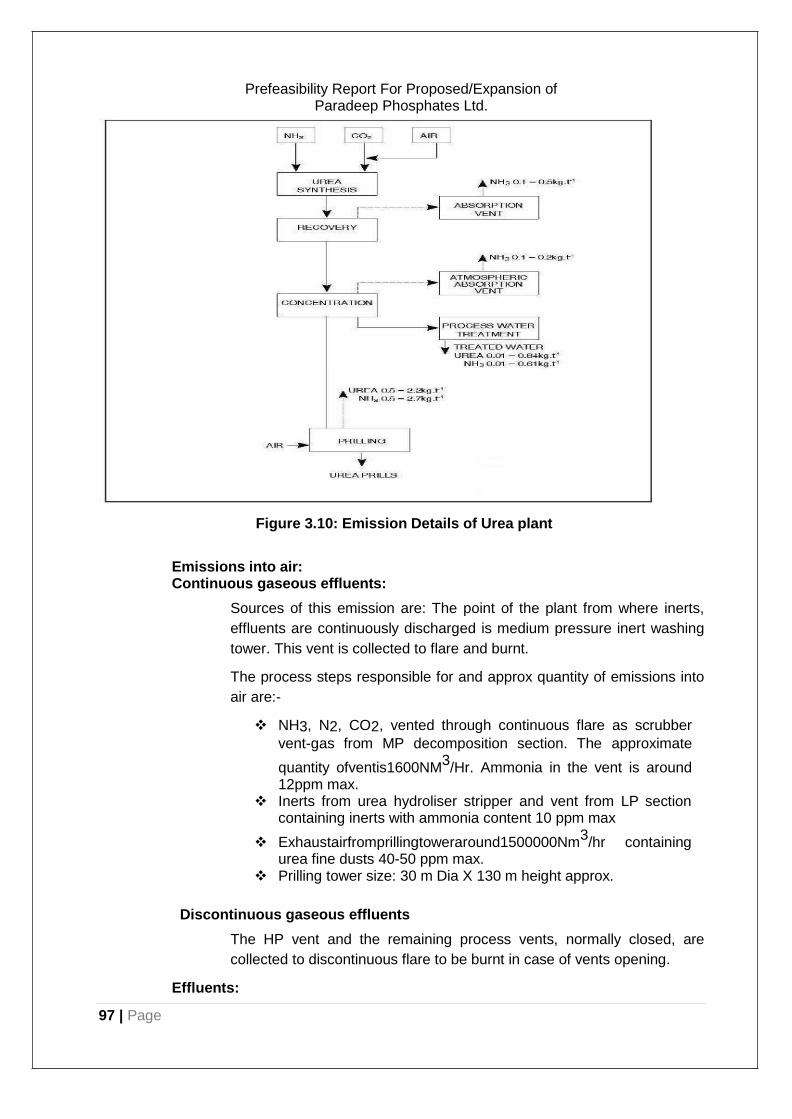
97 | Page
Prefeasibility Report For Proposed/Expansion of Paradeep Phosphates Ltd.
Figure 3.10: Emission Details of Urea plant
Emissions into air: Continuous gaseous effluents:
Sources of this emission are: The point of the plant from where inerts,
effluents are continuously discharged is medium pressure inert washing
tower. This vent is collected to flare and burnt.
The process steps responsible for and approx quantity of emissions into
air are:-
❖ NH3, N2, CO2, vented through continuous flare as scrubber
vent-gas from MP decomposition section. The approximate
quantity ofventis1600NM3/Hr. Ammonia in the vent is around
12ppm max. ❖ Inerts from urea hydroliser stripper and vent from LP section
containing inerts with ammonia content 10 ppm max
❖ Exhaustairfromprillingtoweraround1500000Nm3/hr containing
urea fine dusts 40-50 ppm max. ❖ Prilling tower size: 30 m Dia X 130 m height approx.
Discontinuous gaseous effluents
The HP vent and the remaining process vents, normally closed, are
collected to discontinuous flare to be burnt in case of vents opening.
Effluents:
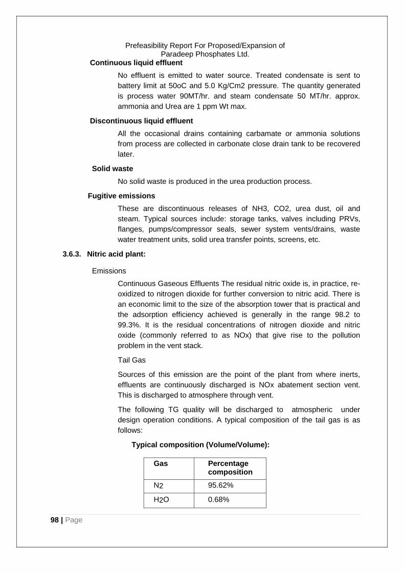
98 | Page
Prefeasibility Report For Proposed/Expansion of Paradeep Phosphates Ltd.
Continuous liquid effluent
No effluent is emitted to water source. Treated condensate is sent to
battery limit at 50oC and 5.0 Kg/Cm2 pressure. The quantity generated
is process water 90MT/hr. and steam condensate 50 MT/hr. approx.
ammonia and Urea are 1 ppm Wt max.
Discontinuous liquid effluent
All the occasional drains containing carbamate or ammonia solutions
from process are collected in carbonate close drain tank to be recovered
later.
Solid waste
No solid waste is produced in the urea production process.
Fugitive emissions
These are discontinuous releases of NH3, CO2, urea dust, oil and
steam. Typical sources include: storage tanks, valves including PRVs,
flanges, pumps/compressor seals, sewer system vents/drains, waste
water treatment units, solid urea transfer points, screens, etc.
3.6.3. Nitric acid plant:
Emissions
Continuous Gaseous Effluents The residual nitric oxide is, in practice, re-
oxidized to nitrogen dioxide for further conversion to nitric acid. There is
an economic limit to the size of the absorption tower that is practical and
the adsorption efficiency achieved is generally in the range 98.2 to
99.3%. It is the residual concentrations of nitrogen dioxide and nitric
oxide (commonly referred to as NOx) that give rise to the pollution
problem in the vent stack.
Tail Gas
Sources of this emission are the point of the plant from where inerts,
effluents are continuously discharged is NOx abatement section vent.
This is discharged to atmosphere through vent.
The following TG quality will be discharged to atmospheric under
design operation conditions. A typical composition of the tail gas is as
follows:
Typical composition (Volume/Volume):
Gas Percentage composition
N2 95.62%
H2O 0.68%
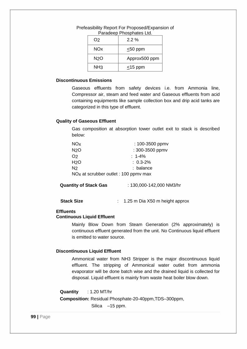
99 | Page
Prefeasibility Report For Proposed/Expansion of Paradeep Phosphates Ltd.
O2 2.2 %
NOx <50 ppm
N2O Approx500 ppm
NH3 <15 ppm
Discontinuous Emissions
Gaseous effluents from safety devices i.e. from Ammonia line,
Compressor air, steam and feed water and Gaseous effluents from acid
containing equipments like sample collection box and drip acid tanks are
categorized in this type of effluent.
Quality of Gaseous Effluent
Gas composition at absorption tower outlet exit to stack is described
below:
NOx : 100-3500 ppmv
N2O : 300-3500 ppmv
O2 : 1-4%
H2O : 0.3-2%
N2 : balance
NOx at scrubber outlet : 100 ppmv max
Quantity of Stack Gas : 130,000-142,000 NM3/hr
Stack Size : 1.25 m Dia X50 m height approx
Effluents Continuous Liquid Effluent
Mainly Blow Down from Steam Generation (2% approximately) is
continuous effluent generated from the unit. No Continuous liquid effluent
is emitted to water source.
Discontinuous Liquid Effluent
Ammonical water from NH3 Stripper is the major discontinuous liquid
effluent. The stripping of Ammonical water outlet from ammonia
evaporator will be done batch wise and the drained liquid is collected for
disposal. Liquid effluent is mainly from waste heat boiler blow down.
Quantity : 1.20 MT/hr
Composition: Residual Phosphate-20-40ppm,TDS–300ppm,
Silica –15 ppm.
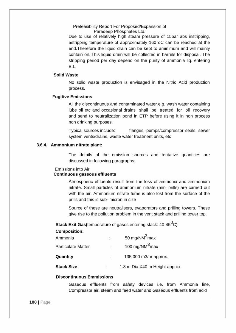
100 | Page
Prefeasibility Report For Proposed/Expansion of Paradeep Phosphates Ltd.
Due to use of relatively high steam pressure of 15bar abs instripping,
astripping temperature of approximately 160 oC can be reached at the
end.Therefore the liquid drain can be kept to aminimum and will mainly
contain oil. This liquid drain will be collected in barrels for disposal. The
stripping period per day depend on the purity of ammonia liq. entering
B.L.
Solid Waste
No solid waste production is envisaged in the Nitric Acid production
process.
Fugitive Emissions
All the discontinuous and contaminated water e.g. wash water containing
lube oil etc and occasional drains shall be treated for oil recovery
and send to neutralization pond in ETP before using it in non process
non drinking purposes.
Typical sources include: flanges, pumps/compressor seals, sewer
system vents/drains, waste water treatment units, etc
3.6.4. Ammonium nitrate plant:
The details of the emission sources and tentative quantities are
discussed in following paragraphs:
Emissions into Air Continuous gaseous effluents
Atmospheric effluents result from the loss of ammonia and ammonium
nitrate. Small particles of ammonium nitrate (mini prills) are carried out
with the air. Ammonium nitrate fume is also lost from the surface of the
prills and this is sub- micron in size
Source of these are neutralisers, evaporators and prilling towers. These
give rise to the pollution problem in the vent stack and prilling tower top.
Stack Exit Gas(temperature of gases entering stack: 40-450C)
Composition:
Ammonia : 50 mg/NM3max
Particulate Matter : 100 mg/NM3max
Quantity : 135,000 m3/hr approx.
Stack Size : 1.8 m Dia X40 m Height approx.
Discontinuous Emmissions
Gaseous effluents from safety devices i.e. from Ammonia line,
Compressor air, steam and feed water and Gaseous effluents from acid
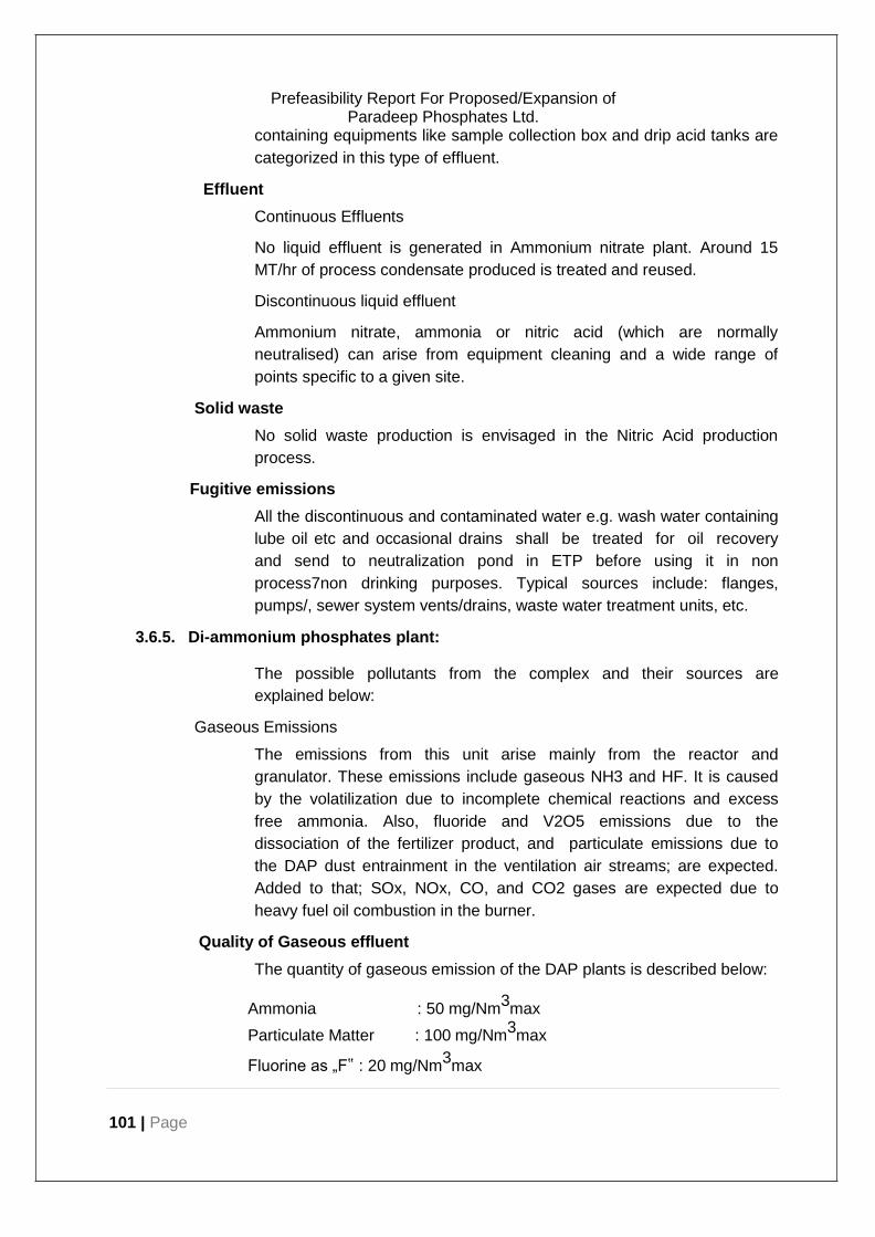
101 | Page
Prefeasibility Report For Proposed/Expansion of Paradeep Phosphates Ltd.
containing equipments like sample collection box and drip acid tanks are
categorized in this type of effluent.
Effluent
Continuous Effluents
No liquid effluent is generated in Ammonium nitrate plant. Around 15
MT/hr of process condensate produced is treated and reused.
Discontinuous liquid effluent
Ammonium nitrate, ammonia or nitric acid (which are normally
neutralised) can arise from equipment cleaning and a wide range of
points specific to a given site.
Solid waste
No solid waste production is envisaged in the Nitric Acid production
process.
Fugitive emissions
All the discontinuous and contaminated water e.g. wash water containing
lube oil etc and occasional drains shall be treated for oil recovery
and send to neutralization pond in ETP before using it in non
process7non drinking purposes. Typical sources include: flanges,
pumps/, sewer system vents/drains, waste water treatment units, etc.
3.6.5. Di-ammonium phosphates plant:
The possible pollutants from the complex and their sources are
explained below:
Gaseous Emissions
The emissions from this unit arise mainly from the reactor and
granulator. These emissions include gaseous NH3 and HF. It is caused
by the volatilization due to incomplete chemical reactions and excess
free ammonia. Also, fluoride and V2O5 emissions due to the
dissociation of the fertilizer product, and particulate emissions due to
the DAP dust entrainment in the ventilation air streams; are expected.
Added to that; SOx, NOx, CO, and CO2 gases are expected due to
heavy fuel oil combustion in the burner.
Quality of Gaseous effluent
The quantity of gaseous emission of the DAP plants is described below:
Ammonia : 50 mg/Nm3max
Particulate Matter : 100 mg/Nm3max
Fluorine as „F‟ : 20 mg/Nm3max
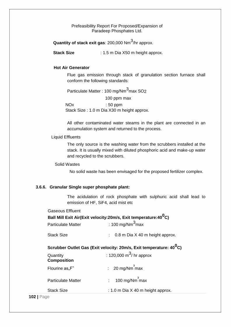
102 | Page
Prefeasibility Report For Proposed/Expansion of Paradeep Phosphates Ltd.
Quantity of stack exit gas: 200,000 Nm3/hr approx.
Stack Size : 1.5 m Dia X50 m height approx.
Hot Air Generator
Flue gas emission through stack of granulation section furnace shall
conform the following standards:
Particulate Matter : 100 mg/Nm3max SO2
100 ppm max
NOx : 50 ppm
Stack Size : 1.0 m Dia X30 m height approx.
All other contaminated water steams in the plant are connected in an
accumulation system and returned to the process.
Liquid Effluents
The only source is the washing water from the scrubbers installed at the
stack. It is usually mixed with diluted phosphoric acid and make-up water
and recycled to the scrubbers.
Solid Wastes
No solid waste has been envisaged for the proposed fertilizer complex.
3.6.6. Granular Single super phosphate plant:
The acidulation of rock phosphate with sulphuric acid shall lead to
emission of HF, SiF4, acid mist etc
Gaseous Effluent
Ball Mill Exit Air(Exit velocity:20m/s, Exit temperature:400C)
Particulate Matter : 100 mg/Nm3max
Stack Size : 0.8 m Dia X 40 m height approx.
Scrubber Outlet Gas (Exit velocity: 20m/s, Exit temperature: 400C)
Quantity : 120,000 m3/ hr approx
Composition
Flourine as„F‟ : 20 mg/Nm³max
Particulate Matter : 100 mg/Nm³max
Stack Size : 1.0 m Dia X 40 m height approx.
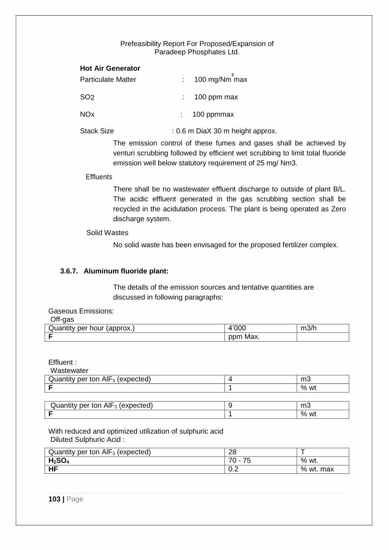
103 | Page
Prefeasibility Report For Proposed/Expansion of Paradeep Phosphates Ltd.
Hot Air Generator
Particulate Matter : 100 mg/Nm³max
SO2 : 100 ppm max
NOx : 100 ppmmax
Stack Size : 0.6 m DiaX 30 m height approx.
The emission control of these fumes and gases shall be achieved by
venturi scrubbing followed by efficient wet scrubbing to limit total fluoride
emission well below statutory requirement of 25 mg/ Nm3.
Effluents
There shall be no wastewater effluent discharge to outside of plant B/L.
The acidic effluent generated in the gas scrubbing section shall be
recycled in the acidulation process. The plant is being operated as Zero
discharge system.
Solid Wastes
No solid waste has been envisaged for the proposed fertilizer complex.
3.6.7. Aluminum fluoride plant:
The details of the emission sources and tentative quantities are
discussed in following paragraphs:
Gaseous Emissions: Off-gas
Quantity per hour (approx.) 4’000 m3/h
F ppm Max.
Effluent : Wastewater
Quantity per ton AlF3 (expected) 4 m3
F 1 % wt
Quantity per ton AlF3 (expected) 9 m3
F 1 % wt
With reduced and optimized utilization of sulphuric acid Diluted Sulphuric Acid :
Quantity per ton AlF3 (expected) 28 T
H2SO4 70 - 75 % wt.
HF 0.2 % wt. max
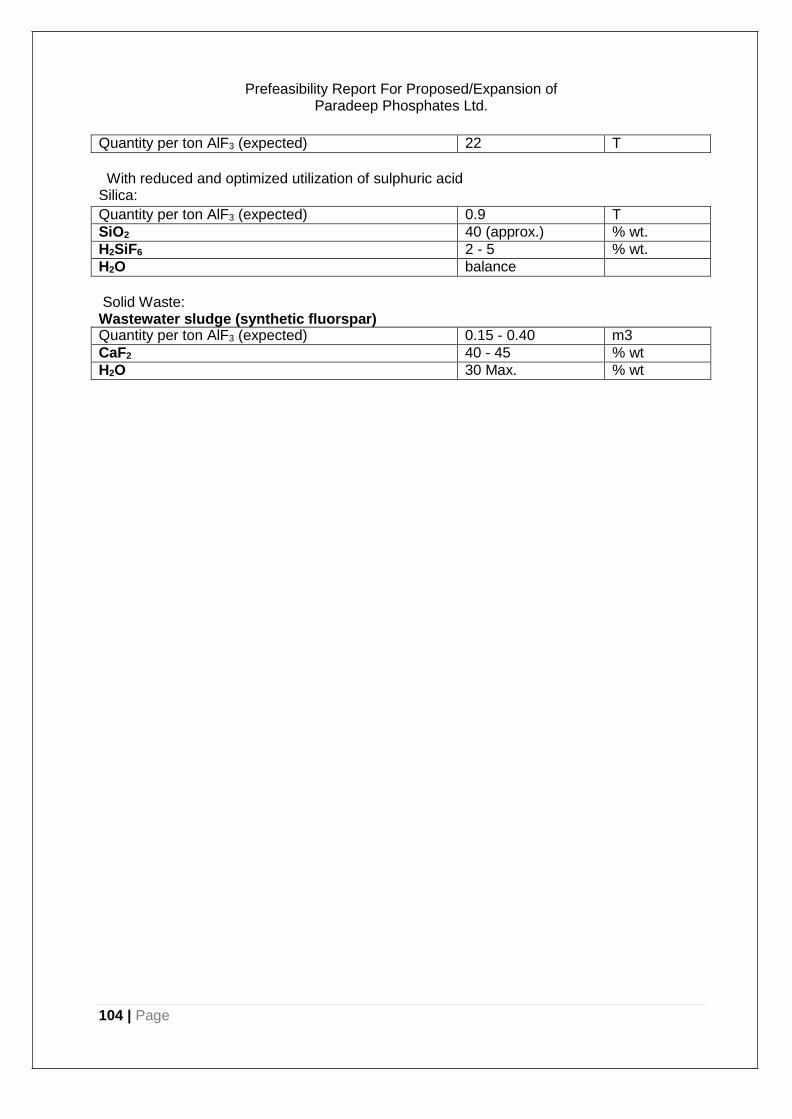
104 | Page
Prefeasibility Report For Proposed/Expansion of Paradeep Phosphates Ltd.
Quantity per ton AlF3 (expected) 22 T
With reduced and optimized utilization of sulphuric acid Silica:
Quantity per ton AlF3 (expected) 0.9 T
SiO2 40 (approx.) % wt.
H2SiF6 2 - 5 % wt.
H2O balance
Solid Waste: Wastewater sludge (synthetic fluorspar) Quantity per ton AlF3 (expected) 0.15 - 0.40 m3
CaF2 40 - 45 % wt
H2O 30 Max. % wt
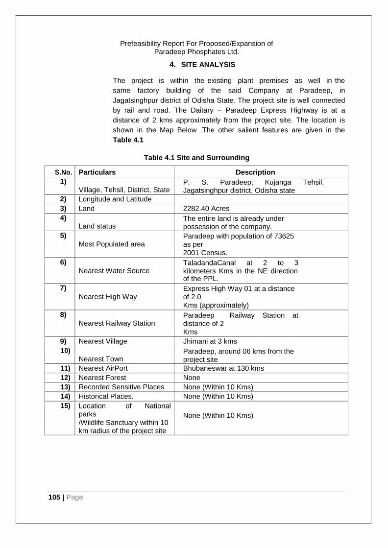
105 | Page
Prefeasibility Report For Proposed/Expansion of Paradeep Phosphates Ltd.
4. SITE ANALYSIS
The project is within the existing plant premises as well in the
same factory building of the said Company at Paradeep, in
Jagatsinghpur district of Odisha State. The project site is well connected
by rail and road. The Daitary – Paradeep Express Highway is at a
distance of 2 kms approximately from the project site. The location is
shown in the Map Below .The other salient features are given in the
Table 4.1
Table 4.1 Site and Surrounding
S.No. Particulars Description
1) Village, Tehsil, District, State
P. S. Paradeep, Kujanga Tehsil, Jagatsinghpur district, Odisha state
2) Longitude and Latitude
3) Land 2282.40 Acres
4) Land status
The entire land is already under possession of the company.
5) Most Populated area
Paradeep with population of 73625 as per 2001 Census.
6) Nearest Water Source
TaladandaCanal at 2 to 3 kilometers Kms in the NE direction of the PPL.
7) Nearest High Way
Express High Way 01 at a distance of 2.0
Kms (approximately)
8) Nearest Railway Station
Paradeep distance of 2 Kms
Railway Station at
9) Nearest Village Jhimani at 3 kms
10) Nearest Town
Paradeep, around 06 kms from the project site
11) Nearest AirPort Bhubaneswar at 130 kms
12) Nearest Forest None
13) Recorded Sensitive Places None (Within 10 Kms)
14) Historical Places. None (Within 10 Kms)
15) Location of National parks
/Wildlife Sanctuary within 10 km radius of the project site
None (Within 10 Kms)

106 | Page
Prefeasibility Report For Proposed/Expansion of Paradeep Phosphates Ltd.
Figure 4.1: Satellite view of Site

107 | Page
Prefeasibility Report For Proposed/Expansion of Paradeep Phosphates Ltd.
Figure 4.2: Road Network Map
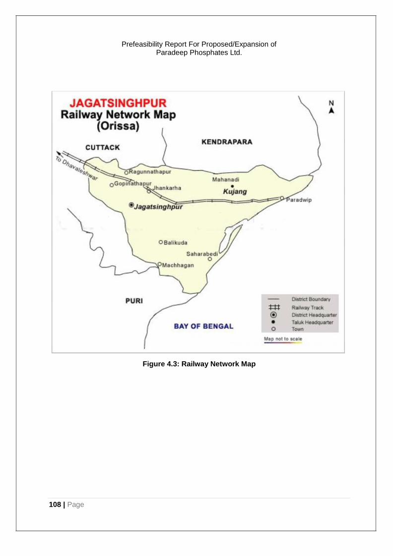
108 | Page
Prefeasibility Report For Proposed/Expansion of Paradeep Phosphates Ltd.
Figure 4.3: Railway Network Map
109 | Page
Prefeasibility Report For Proposed/Expansion of Paradeep Phosphates Ltd.
5. REHABILITATION AND RESETTLEMENT
The objectives of the National Rehabilitation and Resettlement Policy
are: to minimize displacement and to promote, as far as possible, non-
displacing or least- displacing alternatives; to ensure adequate
rehabilitation package and expeditious' implementation of the
rehabilitation process with the active participation of the affected families;
to ensure that special care is being taken for protecting the rights of the
weaker sections of society, especially members of the Scheduled Castes
and Scheduled Tribes, and to create. obligations on the State for their
treatment with concern and sensitivity; to provide a better standard of
living, making concerted efforts for providing sustainable income to the
affected families; to integrate rehabilitation concerns into the
development planning and implementation process; and where
displacement is on account of land acquisition, to facilitate harmonious
relationship between the requiring body and affected families through
mutual cooperation.
In view of above, it is apodictic fact that the proposed project is not
going to acquire any additional land thereby displacing any permanent
settlement. The proposed project shall be installed within the boundary
limit of Paradeep Phosphates Limited fertilizer complex which is located
at Port town of Paradeep in Jagatsinghpur District of Odisha.
This proposed project has been considered to be installed in vacant area
of existing fertilizer complex. Hence Rehabilitation and Resettlement
(R&R) Plan in respect of the affected persons including home
oustees, land oustees and landless labourers does not arise for the
proposed project
110 | Page
Prefeasibility Report For Proposed/Expansion of Paradeep Phosphates Ltd.
6. PROJECT COST AND SCHEDULE
The estimated cost (in Rupees / US dollar) of the proposed project
(plant wise) and the estimated expenditure on pollution control measure
are as given below:
Sl. No.
Plants Cost in Rupees Environmental Measures Cost
1 CHP 2750 Million Adequate provision will be made for meeting the required environmental costs requirements. However this is expected to be of the order of 5-7% of project costs.
2 Ammonia 54489 Million
3 Urea 17605.6 Million
4 Nitric Acid 7907.7 Million
5 Ammonium Nitrate 5839.5 Million
6 Di-Ammonium Phosphate
4417.4 Milliom
7 Granulated single super phosphate
1484 Million
8 Aluminium fluoride 1860000 USD(98.5 million INR)
6.1. Environmental measure expenditure by PPL:
Year Wise Expenditure for implementation of environmental safeguard :
Items Details 2014-15 2015-16 2016-17
Expenditure for implementation of environmental safeguard
269.59 Lakhs 2089.92 Lakhs 10010.2 Lakhs
6.2. Project Implementation schedule:
The proposed project shall be implemented based on either LSTK
(Lump Sum Turnkey) mode or EPCM mode. In LSTK mode, the owner
can engage LSTK engineering contractor for B/L proposed plant, or, if
found more economical or more convenient, PPL may adopt EPCM
mode (cost plus fee mode). In either mode of implementation the overall
project monitoring, progress review, reporting and coordination between
the different agencies could be entrusted to an independent Project
Management consultant. Alternatively, these functions could be
performed by experienced project group, specially set up by the owners
for this purpose.
6.3. Pre-Project Activities
The pre-project activities to be completed before the physical execution
of the project are briefly enumerated below:
a) Preparation of feasibility report and submission of same to DoF for
getting clearance
b) Clearance and approval of the project, by the board of the company.
111 | Page
Prefeasibility Report For Proposed/Expansion of Paradeep Phosphates Ltd.
c) Firming up of arrangement for supply of power & water, ifrequired,
from concerned agency.
d) Preparation of ITB for selection of LSTK/EPCM Contractor for B/L
Plants by appointing an experienced engineering consultant.
e) Selection of Prime Engineering Consultant (PEC). PEC will mainly
prepare engineering packages for all off site and utility units and assist
the Owner in procurement, construction and commissioning
supervision.
f) Soil investigation work for ascertaining soil characteristics of the area
identified for location of the new facilities.
g) Preparation of Environment Impact Assessment (EIA) study and
clearance by State and Central Pollution Control Boards.
h) Preparation of DFR/DPR based on selected LSTK Contractor for B/L
Plants.
i) Preparation of Risk Analysis Study.
j) Final approval of the project by Government.
k) Obtaining financial clearance and commitment from financial
institutions and creditors for financial closure of the project.
All the project execution related activities, as mentioned earlier, are
interlinked and have impact on the final outcome. The execution of the
relevant project activities has to be planned and controlled in such a
way that the goals of the project are achieved in the set time frame.
During the execution, the main time consuming activity is delivery of
critical equipment and machineries. The implementation time is for
mechanical completion & commissioning.
Sl. No. Projects Project Implementation Period
1. Coal Handling Plant 30 Months
2. Gasification based Ammonia Plant 36 Months
3. Urea Plant 36 Months
4. Nitric Acid Plant 24 Months
5. Ammonium Nitrate Plant 24 Months
6. Di-ammonium Phosphate Plant capacity expansion
48 Months
7. Single Super Phosphate Plant 18 Months
8. Aluminium Fluoride Plant 24 Months
Recommended