KOLBENSCHMIDT PIERBURG
MSI Motor Service International GmbH
Hamburger Strasse 15D-41540 DormagenPhone +49 21 33 - 2 67 - 1 00Fax +49 21 33 - 2 67 - 1 11
Untere NeckarstrasseD-74172 NeckarsulmPhone +49 71 32 - 33 33 33Fax +49 71 32 - 33 28 64
Technical Market Service
Phone +49 21 33 - 2 67 - 1 67Fax +49 21 33 - 2 67 - 1 11
Fuel SystemsComponents and solutions for
universal applications
Service
8.40002.57.0 04/03
Tips & Information
2 | Fuel Systems MSI Motor Service International
Fuel Systems
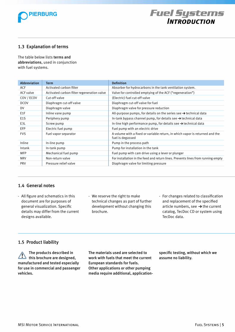
1 Introduction........................................................................................4
1.1 Preface .........................................................................................4
1.2 Pictograms and symbols...............................................................4
1.3 Explanation of terms.....................................................................5
1.4 General notes ...............................................................................5
1.5 Product liability ............................................................................5
1.6 General notes on safety ................................................................6
2 Most Common Fuel Systems ..........................................................7
3 Components..........................................................................................8
3.1 Overview ......................................................................................8
3.2 Electric all-purpose fuel pumps (EFP) ...........................................8
3.2.1 Type E1F .......................................................................................9
3.2.2 Type E1S.....................................................................................10
3.2.2.1 Comments on pre-feeder pumps.................................................10
3.2.3 Type E3L .....................................................................................11
3.2.4 Accessories for pumps................................................................12
3.2.5 Safety shut-off (12 V operation)..................................................13
3.3 Non-return valve (NRV) ...............................................................14
3.4 Fuel cut-off valve (COV/ECOV).....................................................15
3.5 Fuel vapor separator (FVS)..........................................................16
3.6 Pressure relief valve (PRV) ..........................................................17
3.7 Additional accessories for fuel systems ......................................18
3.7.1 Selections from our catalog “Tools & Testing Instruments”........18
3.7.2 Specialist trade items .................................................................18
4 Common Applications .....................................................................19
4.1 General notes .............................................................................19
4.2 Installation of an E1F to replace a mechanical
fuel pump (gasoline engine) .......................................................20
4.3 Gasoline engine with an E1F electric fuel pump ..........................21
4.4 Gasoline engine with two E1F electric fuel pumps.......................22
4.5 Backup pump for gasoline and diesel engines ............................22
4.6 E1F/E1S as a pre-feeder pump (diesel engine) ............................23
4.7 Transfer system/auxiliary tanks..................................................24
4.8 Boat operation............................................................................25
4.9 Fuel supply in heating systems ...................................................25
5 Information on Other Documents.............................................26
6 Tools and Testing Equipment ......................................................27
7 Frequently Asked Questions .......................................................28
Table of Contents

MSI Motor Service International Fuel Systems | 3
Fuel SystemsTable of Contents
8 Troubleshooting Tips.....................................................................30
8.1 General notes .............................................................................30
8.2 Malfunctions, possible causes, remedies ...................................30
8.2.1 General malfunctions .................................................................30
8.2.2 Malfunctions after the installation of new pumps .......................31
8.2.3 Malfunctions particular to diesel operation ................................31
8.2.4 Malfunctions when replacing a mechanical fuel pump
with an E1F (particularly with antique cars).................................32
8.2.5 Notes on operation with biodiesel ..............................................33
9 MSI Training Program
9.1 The MSI training concept ............................................................34
9.2 Scheduled courses for MSI training ............................................34
9.2.1 For engine rebuilders ..................................................................35
9.2.2 For automotive workshops..........................................................36
10 Contact Information.......................................................................37
Subject to change and deviation from the illustrations.
© MSI Motor Service International GmbHVersion 04.03First printingArticle no. 8.40002.57.0

4 | Fuel Systems MSI Motor Service International
Indicates hazardous situations
with possible injury to persons
or damage to vehicle components.
Notes regarding environmental
protection.
Fuel SystemsIntroduction
1 Introduction Please note:
This brochure is intended only for
qualifi ed personnel.
1.1 Preface
Typically gasoline (petrol) or diesel
fuel is required for the operation of
combustion engines.
In addition to that, fuels are also used
for heat generation, as is the case with
heating oil. The fuels must be stored,
transported, transferred and supplied
to the motor or heating system.
The components used to accomplish
this are referred to in general as
“fuel systems”. For mass production
vehicles these systems as well as the
corresponding components are
developed and tested for special-
ized applications. For small series or
1.2 Pictograms and symbols
The following pictograms and symbols
are used in this information brochure:
Qualifi ed personnel are persons
who have, based on their specialist
training, experience and instruction,
suffi cient knowledge of
- safety regulations,
- accident prevention regulations and
- guidelines and accepted rules of
technology (such as standards).
special applications this is often not
the case.
In such cases, the user puts the sys-
tem together according to his needs
and knowledge.
In all cases the fuel pump along with
the reserve fuel container (tank) is the
key component of a fuel system.
Pierburg offers a series of all-purpose
pumps and components.
In the course of our technical consul-
tation and from questions from cus-
tomers, we fi nd time and again that
there are often questions related to
the various systems or that avoidable
problems arise due to mistakes during
installation.
In this brochure we offer a multitude
of information and hints to help you
achieve optimal results and avoid
errors.
Please note:
Information regarding fuel
systems for injection engines can be
found in our brochure “Service Tips &
Info - Fuel Supply for Injection
Engines”
Indicates useful suggestions,
explanations and supplemental
information for use.
Cross reference to another part
of the document.
➔
MSI Motor Service International Fuel Systems | 5
Fuel SystemsIntroduction
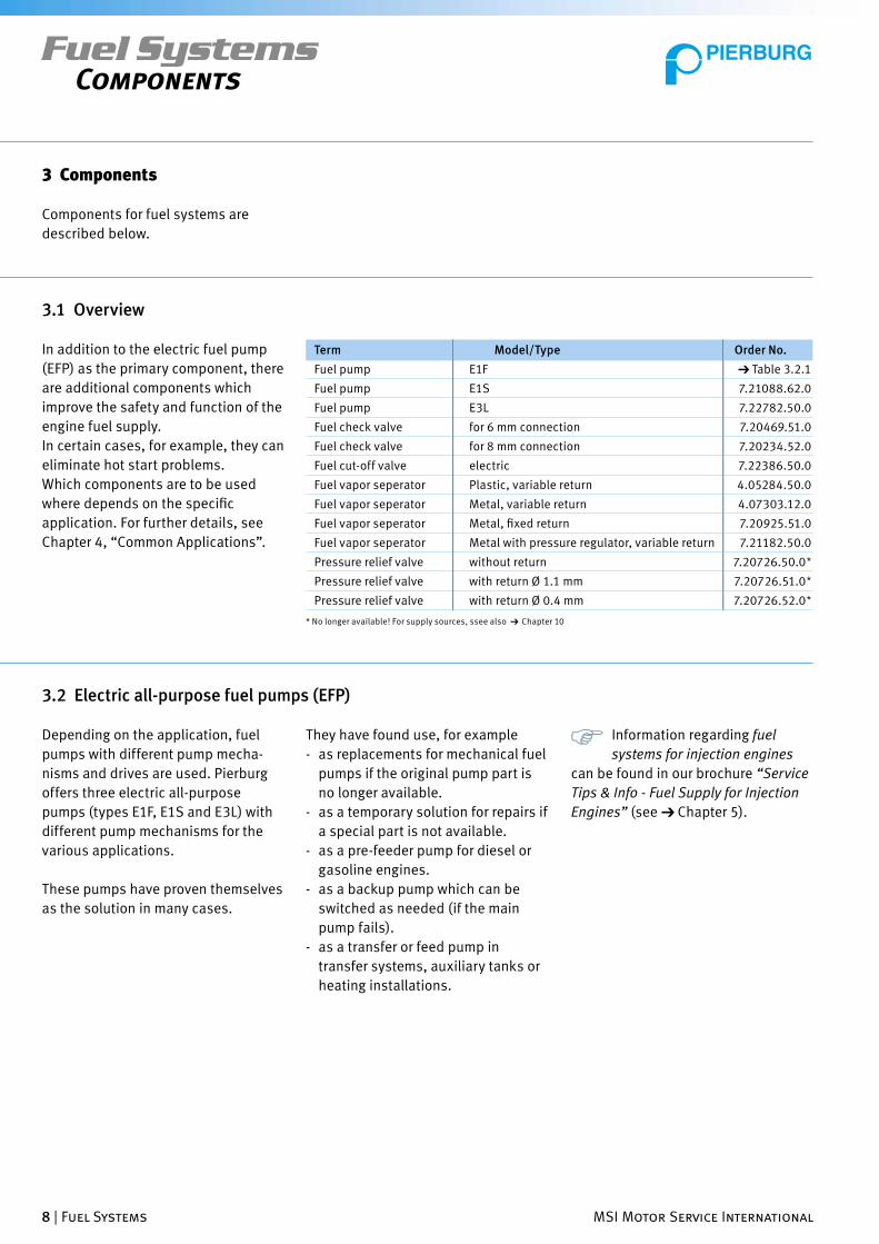
1.3 Explanation of terms
The table below lists terms and
abbreviations, used in conjunction
with fuel systems.
ACF Activated carbon fi lter Absorber for hydrocarbons in the tank ventilation system.
ACF valve Activated carbon fi lter regeneration valve Valve for controlled emptying of the ACF (“regeneration”)
COV / ECOV Cut-off valve (Electric) fuel cut-off valve
DCOV Diaphragm cut-off valve Diaphragm cut-off valve for fuel
DV Diaphragm valve Diaphragm valve for pressure reduction
E1F Inline vane pump All-purpose pumps, for details on the series see ➔ technical data
E1S Periphery pump In-tank bypass channel pump, for details see ➔ technical data
E3L Screw pump In-line high performance pump, for details see ➔ technical data
EFP Electric fuel pump Fuel pump with an electric drive
FVS Fuel vapor separator A volume with a fi xed or variable return, in which vapor is returned and the fuel is degassed
Inline In-line pump Pump in the process path
Intank In-tank pump Pump for installation in the tank
MFP Mechanical fuel pump Fuel pump with cam drive using a lever or plunger
NRV Non-return valve For installation in the feed and return lines. Prevents lines from running empty
PRV Pressure relief valve Diaphragm valve for limiting pressure
Abbreviation Term Defi nition
1.5 Product liability
The products described in
this brochure are designed,
manufactured and tested especially
for use in commercial and passenger
vehicles.
The materials used are selected to
work with fuels that meet the current
European standards for fuels.
Other applications or other pumping
media require additional, application-
specifi c testing, without which we
assume no liability.
1.4 General notes
- All fi gure and schematics in this
document are for purposes of
general visualization. Specifi c
details may differ from the current
designs available.
- We reserve the right to make
technical changes as part of further
development without changing this
brochure.
- For changes related to classifi cation
and replacement of the specifi ed
article numbers, see ➔ the current
catalog, TecDoc CD or system using
TecDoc data.

6 | Fuel Systems MSI Motor Service International
In addition, all country-specifi c safety
regulations must be followed.
Please note that the operating permit
for the vehicle may be voided if
changes are made which
- change the vehicle type approved in
the operating permit,
- may lead to the endangerment of
road users or
- degrade the exhaust or noise
characteristics.
In case of individual changes
contrary to the applicable regu-
lations, the operating permit must be
renewed after obtaining a certifi ed
evaluation from a qualifi ed technical
expert, which should be included in
the vehicle‘s documentation.
Fuel SystemsIntroduction
1.6 General notes on safety
There must be suffi cient ventilation in
the work area.
• Use only fuel lines which meet the
current applicable regulations.
• After work on fuel tanks, test to be
sure that they are free from leaks.
• When working on the fuel system,
the instructions from the vehicle
manufacturer must be followed at all
times
• Use only the appropriate tools for
refi tting work.
• Before beginning work, allow any hot
components in the engine to cool
down.
• Remove all packing material, fasten-
ings and seals for transport, such as
plugs, from the new fuel pumps only
when they are ready to be installed.
• Install only clean parts.
• Keep the work area clean in order to
ensure that no contamination gets
into the fuel system.
Use personal safety equipment
as needed or required by law.
Dispose of lubricants, clean-
ing agents and wastes in an
environmentally appropriate
manner.
• For safety reasons, disassembly and
installation of electric fuel pumps
should only be carried out by a
qualifi ed workshop.
• Personnel responsible for refi tting
must read and understand this
brochure before beginning the work,
especially the parts pertaining to
the subject of safety.
• The applicable country-specifi c
legal provisions and relevant safety
regulations must also be complied
with.
• Safety equipment is not to be dis-
abled or bypassed.
Follow the safety guidelines for
the working with fuel and fuel
vapors. Fuel and fuel vapors are
highly fl ammable.
- smoking,
- open fl ame,
- exposed lights and
- spark-producing actions are strictly
forbidden.

MSI Motor Service International Fuel Systems | 7
Fuel SystemsMost Common Fuel Systems
2 Most Common Fuel Systems
Figure 1 Fuel system of a carburetor engine (until about 1976)
Figure 2 Design of a fuel system with expanded features (about 1976 to 1992)
carburetor
mechanical fuel pump
fuel tank
fuel tank
mechanical fuel pump
non-return valve
fuel vapor separator
pressure regulationg valve
carburetor
Figure 3 Fuel system for an injection engine (after about 1985)
fuel tank
electric fuel pump (in-line)
non-return valve
fuel fi lter
fuel pressure regulator
pre-feeder pump(in tank)
pulsation damper
fuell distributor
activated carbon fi lter regeneration valve
activated carbon fi lter
Fuel systems are built in various ways
for different applications.
Figures 1 to 3 show the design of fuel
systems for the most common auto-
motive applications.
In addition to these applications,
there are many application scenarios
which require a very different de-
sign and selection of parts. Details
of these are described in Chapter 4,
“Common Applications”.
8 | Fuel Systems MSI Motor Service International
Fuel SystemsComponents
3 Components
Fuel pump E1F ➔ Table 3.2.1
Fuel pump E1S 7.21088.62.0
Fuel pump E3L 7.22782.50.0
Fuel check valve for 6 mm connection 7.20469.51.0
Fuel check valve for 8 mm connection 7.20234.52.0
Fuel cut-off valve electric 7.22386.50.0
Fuel vapor seperator Plastic, variable return 4.05284.50.0
Fuel vapor seperator Metal, variable return 4.07303.12.0
Fuel vapor seperator Metal, fi xed return 7.20925.51.0
Fuel vapor seperator Metal with pressure regulator, variable return 7.21182.50.0
Pressure relief valve without return 7.20726.50.0*
Pressure relief valve with return Ø 1.1 mm 7.20726.51.0*
Pressure relief valve with return Ø 0.4 mm 7.20726.52.0*
Term Model/Type Order No.
3.2 Electric all-purpose fuel pumps (EFP)
They have found use, for example
- as replacements for mechanical fuel
pumps if the original pump part is
no longer available.
- as a temporary solution for repairs if
a special part is not available.
- as a pre-feeder pump for diesel or
gasoline engines.
- as a backup pump which can be
switched as needed (if the main
pump fails).
- as a transfer or feed pump in
transfer systems, auxiliary tanks or
heating installations.
Information regarding fuel
systems for injection engines
can be found in our brochure “Service
Tips & Info - Fuel Supply for Injection
Engines” (see ➔ Chapter 5).
3.1 Overview
In addition to the electric fuel pump
(EFP) as the primary component, there
are additional components which
improve the safety and function of the
engine fuel supply.
In certain cases, for example, they can
eliminate hot start problems.
Which components are to be used
where depends on the specifi c
application. For further details, see
Chapter 4, “Common Applications”.
Depending on the application, fuel
pumps with different pump mecha-
nisms and drives are used. Pierburg
offers three electric all-purpose
pumps (types E1F, E1S and E3L) with
different pump mechanisms for the
various applications.
These pumps have proven themselves
as the solution in many cases.
Components for fuel systems are
described below.
* No longer available! For supply sources, ssee also ➔ Chapter 10

0 0.2 0.4 0.6 0.8 1.0 1.2 1.4 1.6 1.8 2.0 p [bar]
0 5 10 15 20 25 p [psi]
120
90
60
30
0
4.8
3.6
2.4
1.2
0
E
BC
D
A
Q [
l/h
]
I [
A]
I (12 V)
I (24 V)
2 31
MSI Motor Service International Fuel Systems | 9
Figure 4 Electric fuel pump, type E1F, dimensions and characteristic curves
3.2.1 Type E1F
The most frequently used pump is the
E1F, an in-line positive displacement
pump with a vane pump mechanism,
for system pressures of 0.1 to 1.0 bar
and 12 or 24 V operation.
This is an all-purpose pump that is
placed in the fuel line.
Maximum suction head:
500 mm (with filled lines).
For 6 volt operation (such as with
vintage cars) we recommend the E1F
no. 7.21440.53.0. When operating at
6 volts, the pressure and flow rate are
reduced to about half.
7.21440.51.0 1 12 0.27–0.38 95 0.10 Ø 38 133.5 84.5 Ø 8 Ø 8 M 2.00 500
7.21440.53.0 2 12* 0.44–0.57 100 0.15 Ø 38 133.5 84.5 Ø 8 Ø 8 M 2.05 500
7.21440.63.0 2 24 0.44–0.57 100 0.15 Ø 38 134.2 84.5 Ø 8 Ø 8 M 1.35 500
7.21440.78.0 3 12 > 1.85 95 1.00 Ø 38 141.5 91.0 Ø 12 Ø 8 M 4.30 500
7.21440.68.0 3 24 > 1.85 95 1.00 Ø 38 139.5 90.5 Ø 8 Ø 8 M 3.00 500
*) also suited for 6 V operation
E1F technical data
Pierburg No.: rated Stat. P at Flow System Installation or Connection Dim. Current Max.
V Q = 0 l/h Rate Pressure (see ➔ Figure 4) Draw Suction
at Head
[bar] [l/h] [bar] A B C D E [A] [mm]
Cu
rve
Fuel SystemsComponents
Q = fl ow rate; p = pump pressure; I = current input

0 0.1 0.2 0.3 0.4 p [bar]
0 1 2 3 4 5 p [psi]
400
300
200
100
0
4
3
2
1
0E
BC
D
A
Q [
l/h
]
I [
A]
Ø 54.5
Q
I
10 | Fuel Systems MSI Motor Service International
Maximum suction head: 0 mm
The pump must be placed in
the medium to be pumped.
3.2.2 Type E1S
For installation in a fuel tank, there
is the 12 volt version of the E1S, a
fl ow pump with a side channel pump
mechanism. This pump is preferably
used as a pre-feeder pump (up to
approx. 220 l/h).
3.2.2.1 Comments on pre-feeder pumps
cause vapor bubbles to form, leading
to malfunctions. Wear and tear and
damage to the pump can result.
Pre-feeder pumps (such as type E1S,
see ➔ section 3.2.2) are used in order
to avoid this.
Pumps of type E1S can be used as a
pre-feeder pump for up to a fl ow rate
of 220 l/h.
Pre-feeder pumps deliver the medium
to the main pump at lower pressure.
This prevents a vacuum from occur-
ring on the intake side of the main
pump.
Flow pumps are the typical choice for
pre-feeder pumps. They are not self-
priming and must therefore be placed
in the tank.
Installation example, see ➔
section 4.6
Figure 5 Electric fuel pump, type E1S, dimensions and characteristic curve (including prefi lter)
Fuel SystemsComponents
A pressure differential arises between
the fuel tank and the intake side of
in-line fuel pumps.
It is dependent on
- the “free cross section” (internal
diameter) of the intake line,
- the viscosity of the medium to be
pumped and
- the fl ow rate.
As a result of this pressure differen-
tial, the vacuum which occurs may
Q = fl ow rate; p = pump pressure; I = current input
7.21088.62.0 12 – 75 0.24 Ø 38 100 75.3 Ø 9.5 Ø 19 2.00 0
E1S technical data
Pierburg No.: Rated Stat. P at Flow System Installation or Connection Dim. Current Max.
voltage Q=0 l/h Rate Pressure (see ➔ Figure 5) Draw Suction
at Head
[V] [bar] [l/h] [bar] A B C D E [A] [mm]

7 8 9 10 11 12 13 14 15 16
360
320
280
240
200
160
120
80
40
0
E
BC
D
A
Q [
l/h
]
I [
A]
Ø 54.5
18
16
14
12
10
8
6
4
2
0
U [V]
Q
I
MSI Motor Service International Fuel Systems | 11
Maximum suction head:
500 mm (with fi lled lines).
3.2.3 Type E3L
The E3L pump is an in-line pump with
a screw pump mechanism. This pump
is particularly effi cient, quiet and uses
comparatively little power even at
high pressures.
It is suited for system pressures up to
4 bar and has an output of up to
280 l/h (depending on pressure) with
a current consumption of 8 A (for 12 V
operation).
Fuel SystemsComponents
Figure 6 Electric fuel pump, type E3L, dimensions and characteristic curves (at 1.8 bar, 20°C)
Q = fl ow ratee; U = voltage; I = current input
7.22782.50.0 12 – 280–120 - 4.00 Ø 43.5 199.5 156 Ø 9 Ø 9 8.00 500
E3L technical data
Pierburg No. Rated Stat. P Flow System Installation or Connection Dim. Current Max.
voltage at Q=0 l/h Rate Pressure (See ➔ Fig. 6) Draw Suction
at Head
[Volt] [bar] [l/h] [bar] A B C D E [A] [mm]
See also our ➔ catalog “Tools
and Testing Instruments”
35
15
M 6
Ø 2
2
8 mm
6 mm
57
Ø 6.7
10
Ø 6
1.5
Ø 38
12 | Fuel Systems MSI Motor Service International
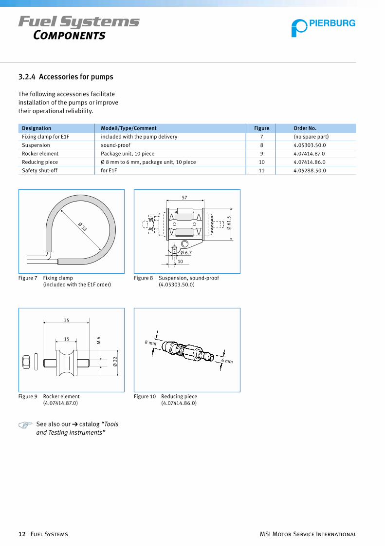
Figure 8 Suspension, sound-proof (4.05303.50.0)
Figure 7 Fixing clamp (included with the E1F order)
Figure 9 Rocker element (4.07414.87.0)
Fuel SystemsComponents
3.2.4 Accessories for pumps
The following accessories facilitate
installation of the pumps or improve
their operational reliability.
Fixing clamp for E1F included with the pump delivery 7 (no spare part)
Suspension sound-proof 8 4.05303.50.0
Rocker element Package unit, 10 piece 9 4.07414.87.0
Reducing piece Ø 8 mm to 6 mm, package unit, 10 piece 10 4.07414.86.0
Safety shut-off for E1F 11 4.05288.50.0
Designation Modell/Type/Comment Figure Order No.
Figure 10 Reducing piece (4.07414.86.0)
1 2 3
654
7 8 9
MSI Motor Service International Fuel Systems | 13
Fuel SystemsComponents
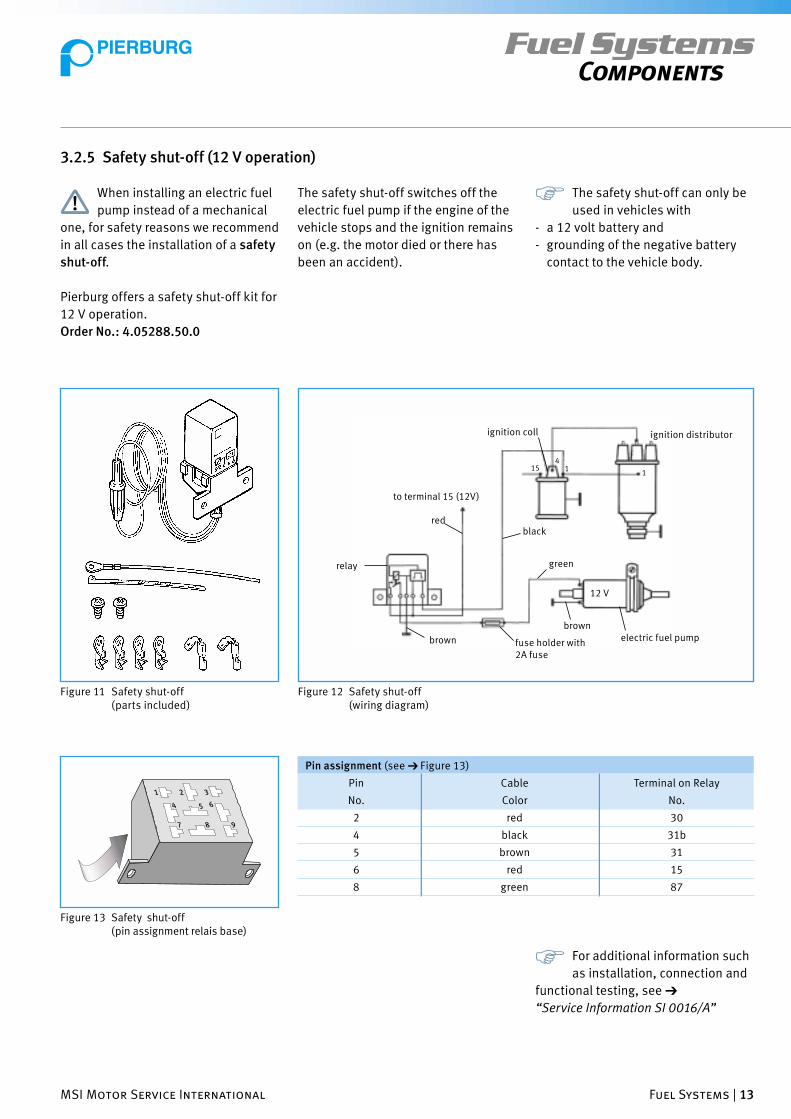
Figure 11 Safety shut-off (parts included)
Figure 12 Safety shut-off(wiring diagram)
to terminal 15 (12V)
red
relay
brown fuse holder with 2A fuse
brownelectric fuel pump
ignition distributor ignition coll
black
green
154
11
12 V
Figure 13 Safety shut-off (pin assignment relais base)
2 red 30
4 black 31b
5 brown 31
6 red 15
8 green 87
Pin Cable Terminal on Relay
No. Color No.
3.2.5 Safety shut-off (12 V operation)
The safety shut-off switches off the
electric fuel pump if the engine of the
vehicle stops and the ignition remains
on (e.g. the motor died or there has
been an accident).
The safety shut-off can only be
used in vehicles with
- a 12 volt battery and
- grounding of the negative battery
contact to the vehicle body.
When installing an electric fuel
pump instead of a mechanical
one, for safety reasons we recommend
in all cases the installation of a safety
shut-off.
Pierburg offers a safety shut-off kit for
12 V operation.
Order No.: 4.05288.50.0
For additional information such
as installation, connection and
functional testing, see ➔
“Service Information SI 0016/A”
Pin assignment (see ➔ Figure 13)

Ø 7
2.5
Ø 6
Ø 4
Ø 18
Ø 4
Ø 6
Ø 7
4
20
62
20
2.5
4
Ø 9
Ø 6
Ø 8
Ø 8
Ø 6
Ø 9
Ø 18
61
.5
20
20
2.5
2.5
14 | Fuel Systems MSI Motor Service International
3.3 Non-return valve (NRV)
Non-return valves are used in various
parts of fuel systems.
For additional information and
details, see ➔ “Service Infor-
mation SI 0044”
Application examples for non-return
valves
(For further details, see ➔ Chapter 5)
• NRV in the supply line
They prevent line voids not only for
carburetor engines, but for injection
and diesel engines as well.
The installation (between the tank
and pump, near the tank), also as a
retrofi t, reduces starting problems,
because the engine fuel lines are
already fi lled when the engine starts.
• NRV in both supply lines
For multiple pumps, regardless of
whether they have a parallel or
separate power supply, in order to
avoid uncontrolled supply circulation.
Fuel SystemsComponents
Figure 15 Non-return valve, 8 mm (7.20234.52.0)
• NRV in the return line
- Used as a safety valve near the tank
in order to prevent it from draining if
a line ruptures.
- Used near the carburetor or before
the fuel vapor separator, to avoid
fl ooding the fl oat chamber from the
return line if the vehicle tilts sharply.
• NRV in the intake line
For diesel engines, an auxiliary tank
or transfer system, the NRV prevents
emptying of the intake line. In some
cases another NRV must be placed on
the tank end of the fuel line.
Figure 14 Non-return valve, 6 mm (7.20469.51.0)

Ø 8
Ø 8
Ø 8
Ø 8
MSI Motor Service International Fuel Systems | 15
Fuel SystemsComponents
Figure 16 Fuel cut-off valve (7.22386.50.0)
3.4 Fuel cut-off valve (COV/ECOV)
Fuel cut-off valves are used in the
supply line.
Depending on the control, they are
used as follows:
- Drain locks to prevent fuel running
out when the motor is turned off.
- Safety shut-offs
- Anti-theft devices
There are two valves available currently:
Connection 1
Connection 2
Ø 8
Connection 2 Connection 1
Connection 3
Figure 17 Fuel cut-off valve (7.22687.07.0)
Technical data
Rated voltage 12 [V]
Pull-in voltage 8 [V]
Connections 2, Ø 8 [mm]
Flow rate at 0.3 bar <_ 100 [l/h]
Length 78.5 [mm]
- The valve is closed in an unpowered
state
- Connection 1 is the pressure inlet.
- Mounting with a clip or custom
bracket supplied by the customer.
Technical data
Rated voltage 12 [V]
Pull-in voltage 8 [V]
Connections 3, Ø 8 [mm]
Flow rate at 0.3 bar <_ 100 [l/h]
Length 85 [mm]
- Without power the path between
connections 1 and 3 of the valve is
open.
- Without power the path between
connections 2 and 3 of the valve is
closed.
- Connection 2 is the pressure inlet.
- Connection 3 is the pressure outlet
When used as a cut-off valve,
connection 1 must be securely
closed.
Ø 7
Ø 7
Ø 7 R
Ø 7
Ø 7
Ø 7
R
R
Ø 7
Ø 7R
Ø 7
Ø 9
Ø 7
Ø 9
R
16 | Fuel Systems MSI Motor Service International
Fuel SystemsComponents
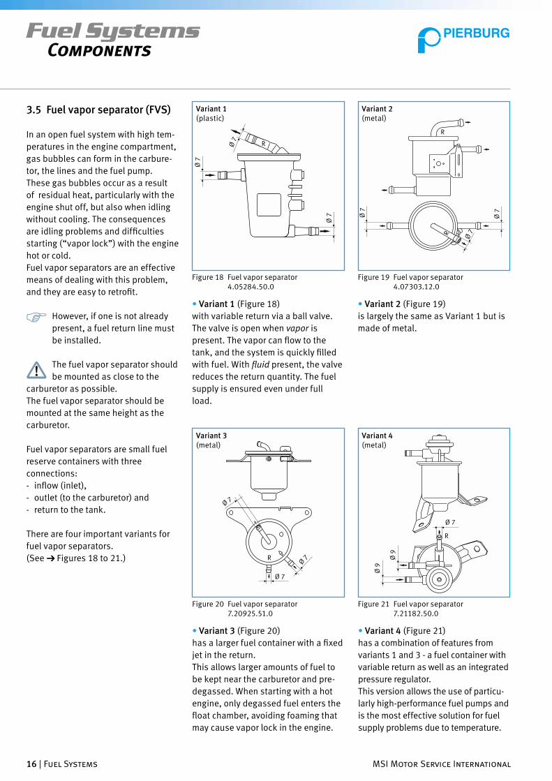
3.5 Fuel vapor separator (FVS)
In an open fuel system with high tem-
peratures in the engine compartment,
gas bubbles can form in the carbure-
tor, the lines and the fuel pump.
These gas bubbles occur as a result
of residual heat, particularly with the
engine shut off, but also when idling
without cooling. The consequences
are idling problems and diffi culties
starting (“vapor lock”) with the engine
hot or cold.
Fuel vapor separators are an effective
means of dealing with this problem,
and they are easy to retrofi t.
However, if one is not already
present, a fuel return line must
be installed.
The fuel vapor separator should
be mounted as close to the
carburetor as possible.
The fuel vapor separator should be
mounted at the same height as the
carburetor.
Fuel vapor separators are small fuel
reserve containers with three
connections:
- infl ow (inlet),
- outlet (to the carburetor) and
- return to the tank.
There are four important variants for
fuel vapor separators.
(See ➔ Figures 18 to 21.)
Variant 1(plastic)
Figure 18 Fuel vapor separator 4.05284.50.0
Variant 2(metal)
Figure 19 Fuel vapor separator 4.07303.12.0
• Variant 1 (Figure 18)
with variable return via a ball valve.
The valve is open when vapor is
present. The vapor can fl ow to the
tank, and the system is quickly fi lled
with fuel. With fl uid present, the valve
reduces the return quantity. The fuel
supply is ensured even under full
load.
• Variant 2 (Figure 19)
is largely the same as Variant 1 but is
made of metal.
Variant 3(metal)
Figure 20 Fuel vapor separator7.20925.51.0
Variant 4(metal)
Figure 21 Fuel vapor separator7.21182.50.0
• Variant 3 (Figure 20)
has a larger fuel container with a fi xed
jet in the return.
This allows larger amounts of fuel to
be kept near the carburetor and pre-
degassed. When starting with a hot
engine, only degassed fuel enters the
fl oat chamber, avoiding foaming that
may cause vapor lock in the engine.
• Variant 4 (Figure 21)
has a combination of features from
variants 1 and 3 - a fuel container with
variable return as well as an integrated
pressure regulator.
This version allows the use of particu-
larly high-performance fuel pumps and
is the most effective solution for fuel
supply problems due to temperature.

Ø 9
Ø 33
Ø 9
Ø 42
52
Ø 9
Ø 33
Ø 9
Ø 42
Ø 7
52
MSI Motor Service International Fuel Systems | 17
Fuel SystemsComponents
3.6 Pressure relief valve (PRV)
Pressure relief valves reduce the fuel
pressure to about 35 to 45% of the
inlet pressure. They are installed in
the supply line before the carburetor.
There are PRVs with and without
return.
When using a fuel vapor sepa-
rator, only pressure relief valves
without a return may be used.
The use of a pressure relief valve has
three advantages.
1. The level in the fl oat chamber
remains largely constant.
2. Foaming of the fuel is prevented
when starting the engine hot.
3. Fuel pumps with higher pressure
and greater delivery rates can be
used.
Figure 22 Pressure relief valve without return (7.20726.50.0*)
Fuel inlet pressure: approx. 0.3 bar
Fuel outlet pressure: approx. 0.13 bar
Figure 23 Pressure relief valve with return(7.20726.51.0*)
Fuel inlet pressure: approx. 0.3 bar
Fuel outlet pressure: approx. 0.13 bar
* No longer available! For supply sourcess, see also ➔ Chapter 10

18 | Fuel Systems MSI Motor Service International
Fuel SystemsComponents
3.7 Additional accessories for fuel systems
In this chapter you will fi nd additional
accessories to make refi tting easier
3.7.1 Selections from our catalog “Tools & Testing Instruments”
T-piece 6 mm Ø 10 units 4.07413.99.0
Y-piece 6 mm Ø 10 units 4.07413.98.0
Tee 8 mm Ø 10 units 4.07414.01.0
Y-piece 8 mm Ø 10 units 4.07414.00.0
Fuel hose (rubber) 5.5 mm Ø 20 m 4.07371.05.0
Fuel hose (rubber) 7.5 mm Ø 20 m 4.07371.06.0
Assortment of hose connectors and clamps * 4.00005.01.0
Filter sieve 4.00030.80.0
*) Contents sorted, 285 connectors and 80 clamps
Article Quantity Order No.
Figure 24 Filter sieve
3.7.2 Specialist trade items
In addition, we recommend that the
following commercially available ac-
cessories be used.
- Fuel line (plastic, white) Ø 6 mm
- Fuel line (plastic, black) Ø 6 mm
- Bulkhead fi tting, straight DS-K 6L
- Elbow bulkhead fi tting DS-L 6L
- Bulkhead fi tting, straight DS-K 8L
- Elbow bulkhead fi tting DS-L 8L
Use only fuel lines which meet
the current applicable
regulations!
Figure 25 Straight bulkhead fi tting
Figure 26 Elbow bulkhead fi tting
and increase operational reliability.
We offer the following accessories for
installation.
tank wall
sealing rings
tank wall
sealing rings
DS-K 6LDS-K 8L
DS-K 6LDS-K 8L

MSI Motor Service International Fuel Systems | 19
Fuel SystemsCommon Applications
4 Common Applications
In sections 4.2 to 4.9 of this chap-
ter, the most common applications
and installation scenarios for fuel
system pumps and components are
described, taken from the range of
applications of our customers.
First, however, section 4.1 presents
some general information which must
be taken into account.
Depending on the application we strong-
ly recommend running tests to ensure
that the fuel system functions reliably.
The comments on the illustrations
(application-specifi c notes) apply only
to the application being shown.
4.1 General notes
In order to ensure operational reliabil-
ity, the following must be considered
when designing fuel systems, particu-
larly with respect to the installation of
the electric fuel pump:
- The pumps of type E1F and E3L are
in-line pumps. They are placed in
the line.
- The E1S, an in-tank pump, may only
be installed in the tank.
- All modern pumps are driven elec-
tromotively. The engines “run wet”,
which means that the fuel passes
through the drive and serves as a
coolant at the same time.
There must always be a fl ow to
maintain proper function and
cooling.
Generally this can only be achieved
with a return line.
The pumps are electrically wired
such that they feed continuously
when there is current available.
With low or no throughput, the
current consumption increases, but
little cooling takes place.
The consequences of this are vapor
formation in the pump, problems
with the fuel supply for the engine,
and subsequent excessive wear on
the pump.
A return is needed to avoid this.
- In contrast to modern pumps,
mechanical pumps or older
electromagnetic models switch
off when the target pressure is
reached and turn on again when
the pressure drops. Diaphragm or
piston pumps work even at higher
suction heads. Larger pressure
heads on the other hand are a
problem.
- For modern electric pumps the
reverse is true; they pressurize well.
Suction heads however should be
avoided. They may cause the pump
to run dry.
Dry running very quickly causes
damage to the pump mecha-
nism. To avoid this, the pumps must
be mounted low (“wet”, under the
fl uid level), near the tank. This avoids
intake bottlenecks.
If this is not possible, an E1S should
be placed in the tank as a pre-feeder
pump (see ➔ section 3.2.2.1).
- With periphery pumps like the E1S,
there is a direct relationship be-
tween voltage, RPM, pressure and
fl uid delivery rate.
A stable voltage supply is a
prerequisite for trouble-free
operation.
Please turn the page. Continued on page 20.
- Positive displacement pumps are
sensitive to contamination. Con-
tamination causes wear and tear,
in some cases even jamming of the
pump mechanism and shutdown of
the pump motor. The power con-
sumption increases, cooling fails
and the pump is destroyed. To avoid
this, a fi lter sieve must be placed in
the fuel line before the pump on the
intake side. This fi lter should have
a suffi ciently large fi ltering surface
(depends on the application) and a
porosity of 60 to 100 µm (microns).
Paper fi lters are not suitable.
When used with diesel en-
gines, the sieve insert must be
removed from the pump connection
tube on the intake side.

20 | Fuel Systems MSI Motor Service International
Fuel SystemsCommon Applications
- When retrofi tting an electric fuel
pump, it is necessary to install a
safety shut-off
(see ➔ section 3.2.5).
As long as the ignition is
switched on, the pump delivers
fuel.
In order that the carburetor does not
fl ood if the engine shuts down or fuel
spill if a line ruptures, we recommend
the installation of safety shut-off
4.05288.50.0! (See ➔ Service Infor-
mation “SI 0016/A” )
The safety shut-off ensures that the
fuel pump will be cut off when the
engine is not running.
- Use only fuel-proof materials for
exposed parts (such as rubber
seals).
- Take care during installation that no
materials are put together that can
cause contact corrosion. Thus, for
example, the pump housing (made
of aluminum) may not come in con-
tact with galvanized surfaces.
Follow the safety guidelines
in ➔ section 1.6.
4.2 Installation of an E1F to replace a mechanical fuel pump (gasoline engine)
Older vehicles with gasoline engines
usually have a mechanical fuel pump
driven directly by the engine.
Figure 27 shows a fuel system of the
type built until about 1976 for a
carburetor engine, consisting of the
tank, mechanical fuel pump and
carburetor.
If the mechanical fuel pump is replaced
by an E1F, the system must be extend-
ed accordingly, as shown in Figure 28.
Figure 28 shows the fuel system with
a retrofi tted E1F electric fuel pump,
expanded to include a fi lter sieve, fuel
vapor separator, pressure relief valve
and non-return valve.
This design, albeit with mechanical
fuel pumps, was standard for most
carburetor engines after about 1980.
Installation of an E1F in such a system
is possible without additional retro-
fi tting.
Application-specifi c notes:
The return can be run parallel to the
supply line.
The discharge into the tank should be
via a “bulkhead fi tting”
(see ➔ section 3.7).
If possible it should be mounted on
a cover for the tank (for example the
cover of the tank sensor).
The outlet for the fuel return line
should be down below the normal
level in the tank. If no fuel vapor
separator is used, the return must be
calibrated with a jet so as to ensure
the fuel supply even at at full load.
The mechanical Pump can be by-
passed or removed. If it is removed,
the opening on the engine side must
be sealed oil-tight.
If it is bypassed, the inlet and outlet
should be connected with a piece of
hose to prevent contamination from
getting in.
fuel tank
mechanicalfuel pump
carburetor
air fi lter
Figure 27 Fuel system of a carburetor engine (until about 1976)
If it is desired to keep the “original”
look (for example with antique cars),
the pump can remain in the system
and have the fl ow pass through it, as
long as it does not leak or hinder the
fl ow of fuel.
However this can lead to heat
build-up and the formation of
vapor bubbles.

MSI Motor Service International Fuel Systems | 21
Fuel SystemsCommon Applications
fuel tank electric fuelpump (E1F)
non-return valve
fi lter sieve
mechanicalfuel pump
carburetor
pressurerelief valve
fuel vaporseparatornon-return valve
Figure 28 Fuel system with retrofi t E1F electric fuel pump
With older carburetors having an inade-
quately sized fl oater gauge, installation
of a pressure relief valve is recommend-
ed. This is also the case for installation
of an E1F with higher performance.
Keep in mind the general
comments in ➔ section 4.1.
In 6 volt systems, the pump runs at
half the RPM. The fuel throughput and
pressure are then only about half that
found for 12 volt operation.
Exercise caution when working
on the fuel supply.
There is a danger of explosion!
Follow all applicable safety regulations.
Do not allow contamination to get into
the system.
We recommend the installation of the
safety shut-off 4.05288.50.0!
See ➔ section 3.2.5
4.3 Gasoline engine with an E1F electric fuel pump
Vehicles with a carburetor engine in
which, due to their particular design,
the length of the lines or high tem-
peratures, problems with the fuel
supply may occur oten are equipped
with an electric fuel pump as standard
equipment.
In many cases, the original pump can
be replaced with an E1F without dif-
fi culty.
In these cases, installation of a fuel
vapor separator, pressure relief valve
and non-return valve are also recom-
mended if these are not already part
of the system.
fuel tank non-return valve
fi lter sieve
carburetor
pressuree relief valve
non-return valve
Figure 29 Fuel system with an electric fuel pump (gasoline engine)
electric fuel pump (E1F)
calibrated jet (valve)in the return line
Figure 29 shows a fuel system for a
carburetor engine with an electric fuel
pump (E1F), pressure relief valve and
two non-return valves.
The return is “calibrated” or restricted
with a jet (1.0 to 2.0 mm depending on
the requirements of the engine at full
load). For pressure relief valves with
calibration, the return is connected to
the pressure relief valve.
We recommend the instal-
lation of the safety shut-off
4.05288.50.0!
See ➔ section 3.2.5.
Keep in mind the general
comments in ➔ section 4.1.
22 | Fuel Systems MSI Motor Service International
Fuel SystemsCommon Applications
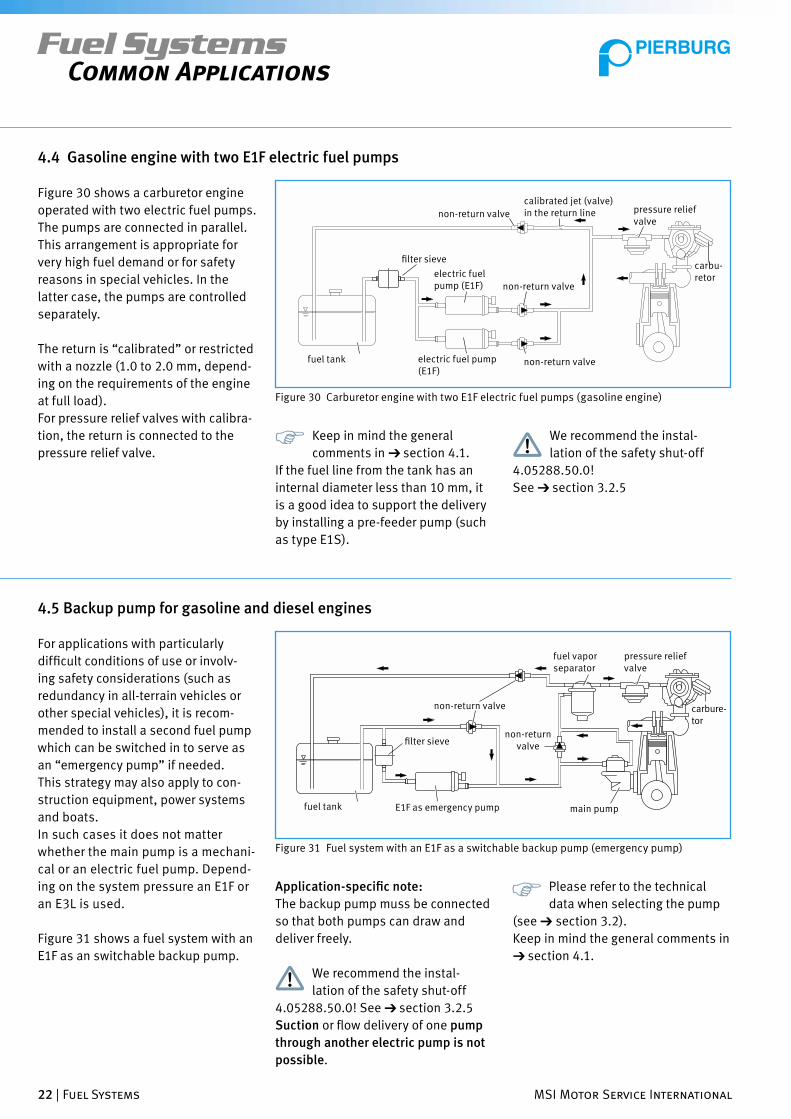
4.4 Gasoline engine with two E1F electric fuel pumps
Figure 30 shows a carburetor engine
operated with two electric fuel pumps.
The pumps are connected in parallel.
This arrangement is appropriate for
very high fuel demand or for safety
reasons in special vehicles. In the
latter case, the pumps are controlled
separately.
The return is “calibrated” or restricted
with a nozzle (1.0 to 2.0 mm, depend-
ing on the requirements of the engine
at full load).
For pressure relief valves with calibra-
tion, the return is connected to the
pressure relief valve.
fuel tank non-return valve
fi lter sievecarbu-retor
pressure relief valve
non-return valve
Figure 30 Carburetor engine with two E1F electric fuel pumps (gasoline engine)
electric fuel pump (E1F)
calibrated jet (valve) in the return line
non-return valve
electric fuel pump (E1F)
Keep in mind the general
comments in ➔ section 4.1.
If the fuel line from the tank has an
internal diameter less than 10 mm, it
is a good idea to support the delivery
by installing a pre-feeder pump (such
as type E1S).
We recommend the instal-
lation of the safety shut-off
4.05288.50.0!
See ➔ section 3.2.5
4.5 Backup pump for gasoline and diesel engines
For applications with particularly
diffi cult conditions of use or involv-
ing safety considerations (such as
redundancy in all-terrain vehicles or
other special vehicles), it is recom-
mended to install a second fuel pump
which can be switched in to serve as
an “emergency pump” if needed.
This strategy may also apply to con-
struction equipment, power systems
and boats.
In such cases it does not matter
whether the main pump is a mechani-
cal or an electric fuel pump. Depend-
ing on the system pressure an E1F or
an E3L is used.
Figure 31 shows a fuel system with an
E1F as an switchable backup pump.
fuel tank main pump
fi lter sieve
carbure-tor
pressure relief valve
non-return valve
Figure 31 Fuel system with an E1F as a switchable backup pump (emergency pump)
E1F as emergency pump
non-return valve
fuel vapor separator
Application-specifi c note:
The backup pump muss be connected
so that both pumps can draw and
deliver freely.
We recommend the instal-
lation of the safety shut-off
4.05288.50.0! See ➔ section 3.2.5
Suction or fl ow delivery of one pump
through another electric pump is not
possible.
Please refer to the technical
data when selecting the pump
(see ➔ section 3.2).
Keep in mind the general comments in
➔ section 4.1.

MSI Motor Service International Fuel Systems | 23
Fuel SystemsCommon Applications
4.6 E1F/E1S as a pre-feeder pump (diesel engine)
Figure 32 shows the standard equip-
ment fuel system for a diesel engine
with an in-line injection pump and
attached mechanical fuel pump (MFP)
as a pre-feeder pump.
For information regarding
pre-feeder pumps, see also
➔ section 3.2.2.1
Figure 33 shows the same system as
Figure 32 with an electric pre-feeder
pump. Instead of the mechanical pre-
feeder pump an E1F is used here. In
addition, a fi lter has been put in the
intake line in front of the E1F. In place
of the E1F an E1S can be used in the
tank.
Application-specifi c note:
The fi lter must have a porosity of 60 to
100 µm (microns) and an area suf-
fi cient to handle the expected amount
of particulate (such as Pierburg fi lter
sieves, see ➔ section 3.7.1)
For diesel operation, the sieve
insert in the pump intake
(intake connection ) be removed be-
fore starting operation.
Figure 34 shows a possible electric
connection method load for a pump of
type E1F in a diesel engine.
fuel tank
non-return valve
Figure 32 Diesel engine with in-line injection pump and attached pre-feeder pump (MFP)
fuel stage fi lter(provided by the customer)
mechanical fuel pump as a pre-feeder pump
fuel tank
non-return valve
Figure 33 Diesel engine with in-line injection pump and attached pre-feeder pump (E1F)
E1F as a pre-feeder pump
MFP as a pre-feeder pump
fuel stage fi lter (pro-vided by the customer)
fi lter sieve
drive switch
starter glow switch
glow plug indicator heat plug resistor
glow plugs, 2 pole
glow plugs, 1 pole
electric fuel pump
fuse holderwith fuse
Figure 34 Electrical connection for an E1F (diesel engine)
Please turn the page. Continued on page 24.
15+30
50
15
19
19 17
17

24 | Fuel Systems MSI Motor Service International
Fuel SystemsCommon Applications
Figure 35 shows an installation
example for a pre-feeder pump.
After work on fuel tanks, test to
be sure that they are free from
leaks.
Use only fuel-proof materials for
exposed parts (such as rubber seals).
Take care during installation that no
material combinations are used that
can cause contact corrosion (such as
aluminum with galvanized surfaces).
Figure 35 Installation example for an in-tank pre-feeder pump.
Keep in mind the general
comments in ➔ section 4.1.
4.7 Transfer system/auxiliary tanks
Long-distance commercial vehicles
are frequently equipped with auxiliary
tanks. During travel, fuel is trans-
ferred as required from the auxiliary
tanks to refi ll the operating tank.
Figure 36 shows a fuel system with
auxiliary tank, in which two electric
fuel pumps are used for transferring
large volumes into the operating tank.
Keep in mind the general
comments in ➔ section 4.1.
For larger delivery volumes or higher
pressures, an E3L can be used instead
of an E1F (only with 12 volt operation).
Ensure that the pumps do not
run dry.
Dry running will quickly lead to
destruction of the pumps.
auxiliary tank E1F (connected in parallel)
fuel tanknon-return valve
E1F (connected in parallel)
non-return valvefi lter sieve
Figure 36 Fuel system with auxiliary tank
MSI Motor Service International Fuel Systems | 25
Fuel SystemsCommon Applications
4.8 Boat operation
For use in boots, installation of an E1F
can be done as shown in Figures 28
and 33. At higher fuel pressure and/or
higher output an E3Lis to be used.
Water in the fuel system leads
to damage and subsequent
destruction of the pump.
The housing of the fuel pumps is not
salt water proof!
We recommend the installation of the
safety shut-off 4.05288.50.0!
See ➔ section 3.2.5
Please refer to the technical
data when selecting the pump
(see ➔ section 3.2).
For use in boat engines, a water
separator is recommended in addition
to a fi lter sieve. Before storage for the
winter the entire system should be
purged of water.
Keep in mind the general comments in
➔ section 4.1.
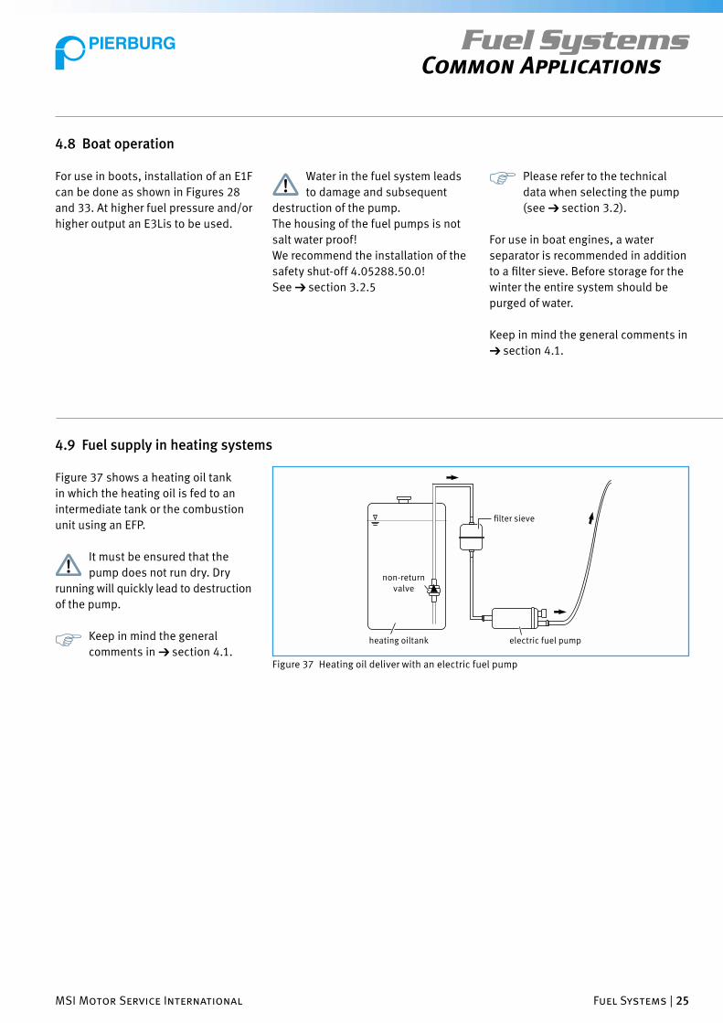
Figure 37 shows a heating oil tank
in which the heating oil is fed to an
intermediate tank or the combustion
unit using an EFP.
It must be ensured that the
pump does not run dry. Dry
running will quickly lead to destruction
of the pump.
Keep in mind the general
comments in ➔ section 4.1. heating oiltank electric fuel pump
fi lter sieve
non-return valve
Figure 37 Heating oil deliver with an electric fuel pump
4.9 Fuel supply in heating systems

26 | Fuel Systems MSI Motor Service International
Fuel SystemsInformation on Other Documents
5 Information on Other Documents
The following additional information
is available on the subject of “fuel
supply”. The documents are updated
and expanded on an on-going basis.
• Catalogs
- Fuel supply article no. 8.40002.47.0
- Tools & Testing Instruments
article no. 50 003 931-02
- MSI Training Program
article no. 50 003 646
• Brochures
- Service, Tips & Info “Fuel Supply for
Injection Engines”
article no. 8.40002.37.0
• Products information PI
- PI 0005 “Fuel pressure tester”
- PI 0007 “Add-ons for the fuel
pressure tester”
- PI 0013 “Electric fuel pump E1F”
- PI 0014 “Fuel pump tester”
- PI 0015 “Electric in-tank fuel pump
E1S”
- PI 0016 “Diesel-resistant electric
universal pump E3L” (for system
pressures up to 4 bar)
• Service Information SI
- SI 0016A “Safety shut-off for
electric fuel pumps”
- SI 0044 “Fuel non-return valves”
- SI 0062 “Installation of an electric
fuel pump E1F to replace a mechani-
cal fuel pump”.
- SI 0063 “Installation of an electric
fuel pump E1F as a backup pump”
• Installation instructions for electric
fuel pumps (included with the
products)
• Installation instructions for safety
shut-off (included with the product)
• Publication 002/2002 “E1F - a pump
for many applications”
• Publication 003/2002 “A pump
solution for antique cars”
Product information (PI) and
service information (SI) are
found on the Pierburg CD (article no.
8.40002.62.0) or as a collection in
“Folder I” (article no. 8.40002.03.0).
They can also be downloaded free of
charge from our Web site
www.msi-motor-service.com
There you will also fi nd additional
information on the subject.
Pierburg sales and service information
can also be obtained from your local
Pierburg distributor or ordered on our
Web site.
MSI Motor Service International Fuel Systems | 27
Fuel SystemsTools and Testing Equipment
6 Tools and Testing Equipment
No special tools are needed for install-
ing or removing the pumps described.
Pierburg offers tool and instruments
that are needed for working on fuel
systems.
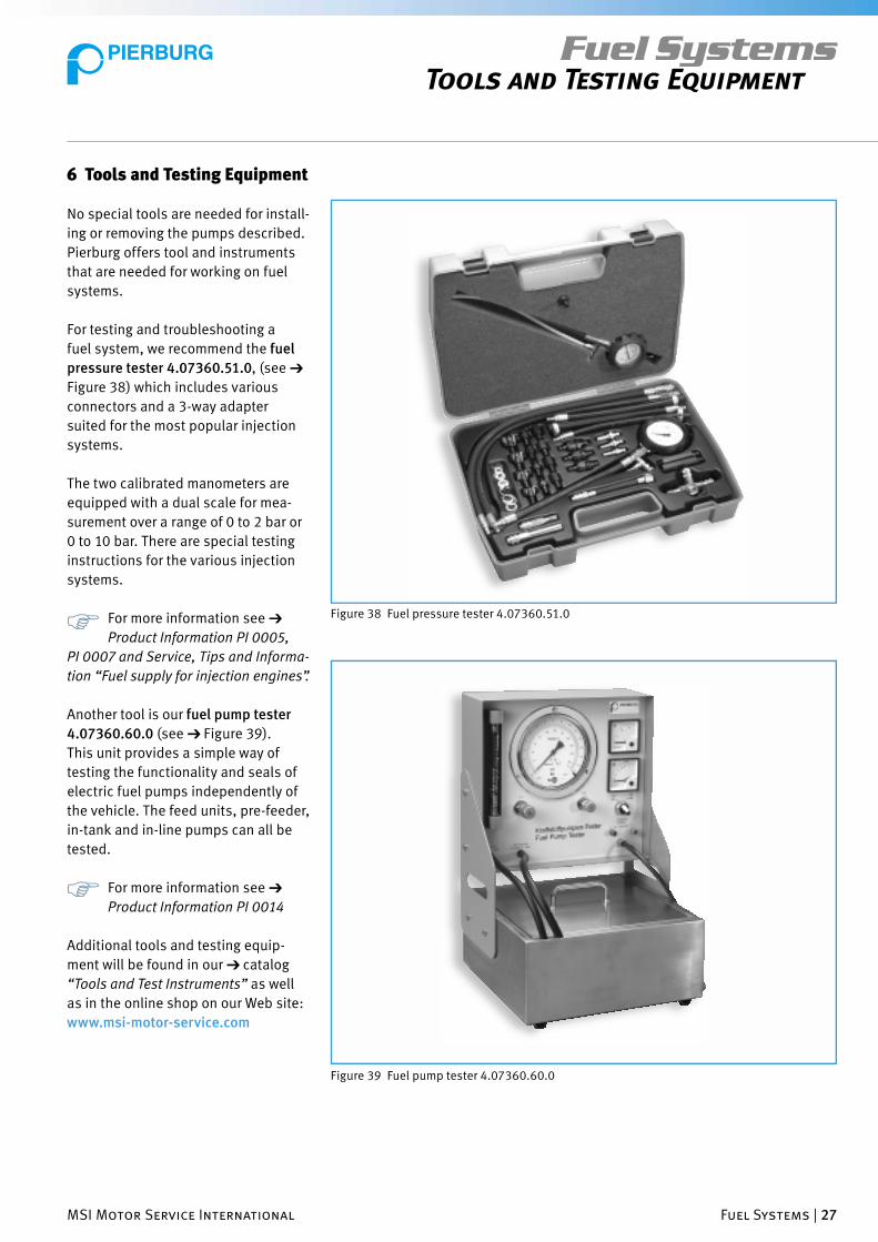
For testing and troubleshooting a
fuel system, we recommend the fuel
pressure tester 4.07360.51.0, (see ➔
Figure 38) which includes various
connectors and a 3-way adapter
suited for the most popular injection
systems.
The two calibrated manometers are
equipped with a dual scale for mea-
surement over a range of 0 to 2 bar or
0 to 10 bar. There are special testing
instructions for the various injection
systems.
For more information see ➔
Product Information PI 0005,
PI 0007 and Service, Tips and Informa-
tion “Fuel supply for injection engines”.
Another tool is our fuel pump tester
4.07360.60.0 (see ➔ Figure 39).
This unit provides a simple way of
testing the functionality and seals of
electric fuel pumps independently of
the vehicle. The feed units, pre-feeder,
in-tank and in-line pumps can all be
tested.
For more information see ➔
Product Information PI 0014
Additional tools and testing equip-
ment will be found in our ➔ catalog
“Tools and Test Instruments” as well
as in the online shop on our Web site:
www.msi-motor-service.com
Figure 38 Fuel pressure tester 4.07360.51.0
Figure 39 Fuel pump tester 4.07360.60.0

28 | Fuel Systems MSI Motor Service International
Fuel SystemsFrequently Asked Questions
7 Frequently Asked Questions
In the following section we have listed
some of the questions we often
encounter in the fi eld.
In addition to brief answers to these
The following abbreviations are
used:
SI Service Information
PI Products Information
See also ➔ Chapter 5 “Information on
Other Documents”.
questions, you will fi nd references to
additional information available from
us that give more details on the
corresponding subject.
Which pump should I use as a replacement The pressure and fl ow rate of the replacement pump ➔ PI 0013, 0015, 0016
pump should correspond to that of the original pump as ➔ SI 0062, 0068
closely as possible. ➔ Catalog: “Fuel Supply”
How high is the fl ow rate of the pump? See ➔ technical data in sections 3.2.1–3.2.3 ➔ PI 0013, 0015, 0016
How high is the pump pressure? ➔ SI 0062, 0063, 0064
How high is the current consumption
of the pump?
What do I do with the existing mechanical By-pass it, hook the inlet and outlet to each other ➔ SI 0062, 0063
pump when retrofi tting with an E1F or remove it and seall the connection fl ange on the ➔ Section 4.1 ”General notes“
electric fuel pump? engine to prevent oil leakage.
How high a suction head can the pumps Type E1F max. 500 mm (with fi lled lines). ➔ SI 0062, 0063, 0064
attain? Type E3L max. 500 mm (with fi lled lines).
Type E1S 0 mm (pressure only!)
Does the E1F electricc fuel pump switch off No, the pumps feed as long as they receive current. ➔ SI 0062, 0063
if the fl oat chamber of the carburetor is full? However the pumps have an overfl ow valve that opens ➔ Section 4.1 “General notes”
when the target pressure is reached. This applies for
pumps only up to < 0.6 bar.
Pumps with higher pressure may only be operated
in a system with a return line.
Does the pump also operate at 6 volts in Yes, but at lower RPM. Thiss also results in lower ➔ SI 0062, 0063
antique cars? pressure and fl ow rate.. For 6 volt operation
(such as with vintage cars) we recommend the
E1F no. 7.21440.53.0.
Can the pump also be used on older Yes. However the electrical connection must be The safety shut-off cannot be
English vehicles where the voltage is set up accordingly (positive connection of the pump used in this case.
supplied via the body? to the body).
The applicable legal provisions and relevant safety
regulations must also be followed.
Is a safeety shut-off necessary? Depending on the regulations of the country in question ➔ SI 0016/A
it may be mandatory. ➔ Section 3.2.5
Is a return line necessary? A return is not mandatory, but for maintaining ➔ SI 0062, 0063
trouble-free function, especially when running hot, ➔ Chapter 4. “Common
a return line is essential. Applications”
Can the pump run “dry” (without fuel) Fundamentally: NO! All pumps run “wet”, i.e. fuel ➔ Section 4.1 “General notes”
for a short time? passes through them. The pumped medium also
provides lubrication and cooling. Dry running will
quckly lead to destruction of the pump.
Questions Answers Additional Information

MSI Motor Service International Fuel Systems | 29
Fuel SystemsFrequently Asked Questions
Is a fuel fi lter necessary? Yes. A prefi lter (fi lter sieve) should be placed in the ➔ SI 0062, 0063
fuel line before the pump on the intake side. Porosity ➔ Section 4.1 “General notes”
of 60 to 100 µm (microns) and particularly for diesel
operation a large fi lter area (such as Pierburg fi lter sieves,
see ➔ section 3.7.1).
Does a 24 volt pump have a longer service No.
life than a 12 volt pump?
The intake port of the pump has a fi lter - what This little fi lter is a protective fi lter. It can be left on for ➔ Section 4.1 “General notes”
about it? gasoline operation. However it must be removed for
diesel operation, because the higher viscosity of diesel
engine at low temperature can lead to problems.
Is it possible to pump through an existing If it is desired to keep the “original” look (for example ➔ Publication 003/2002
pump? with antique cars), a mecanical pump can remain in the “A pump solution for antique
system and have the fl ow pass through it, as long as cars”
it does not leak or hinder the fl ow of fuel. ➔ SI 0062, 0063
Electric fuel pumps, which are designed as positive ➔ Section 4.1 “General notes”
displacement pumps, cannot be in the pumping path.
Questions Answers Additional Information
If you have additional questions,
please contact us at:
Phone +49 21 33 - 2 67 - 1 67
Fax +49 21 33 - 2 67 - 1 11
E-Mail technical.servicePG@ msi-motor-service.com

30 | Fuel Systems MSI Motor Service International
Fuel SystemsTroubleshooting Tips
8 Troubleshooting Tips
Below you will fi nd a table with tips
for troubleshooting. This table only
8.1 General notes
Only cases considered here are those
which could arise in the special appli-
cations previously described. The em-
phasis is on pumps of the E1F series,
simply because of their prevalence.
Malfunctions in injection en-
gines with “standard” equip-
ment are handled in our ➔ brochure
“Service Tips & Information, Fuel
Supply for Injection Engines”.
8.2 Malfunctions, possible causes, remedies
Because this brochure in intended
for qualifi ed personnel, malfunctions
and causes which should be familiar
8.2.1 General malfunctions
applies to malfunctions whose causes
are found in the fuel system.
to persons of this background are not
discussed.
Sympton Malfunction Possible Cause Remedy/Comments
Engine cannot start No fl ow from the pump Voltage supply to the Visual inspection.
cold/warm EFP is faulty. Test the voltage
supply.
Bad fuse. Check and replace if necessary.
Disruption in the line. Check and correct any problems found.
Defective pump relay. Check and replace if necessary
Electrical malfunction Check by measuring resistance
in the pump. or direct current.
Ground (earth) fault Replace the pump if
there is a ground fault.
The engine starts briefl y, No fl ow from the pump. Safety shut-off not working Check the safety shut-off
then dies. properly. for proper function.
Check connections, cables
and ignition signal.
Fuel fi lter/fi lter sieve Check fuel pressure and
clogged. fl ow rate, replace fi lter.
Best performance not achieved, Fuel pressure/fl ow rate fuel fi lter/fi lter sieve Check fuel pressure and
shaking under full load. too low. clogged. fl ow rate, replace fi lter.
Fuel line pinched/bent. Inspect visually, replace as needed.
Faulty tank ventilation. Check tank ventilation
and clean or recondition as
needed.

MSI Motor Service International Fuel Systems | 31
Fuel SystemsTroubleshooting Tips
No fl ow from the new pump. Voltage supply faulty. Fuse burned out. Replace the fuse.
New pump makes noise. Higher resistance on the Filter clogged. Replace the fi lter.
pressure side.
Improper installation. Resonance Check the mounting.
New pump stops after Pump mechanism jammed. Contamination in the fuel If the pump in the vehicle has failed
running briefl y. system. due to contamination, it is absolutely
necessary that the entire fuel
system be cleaned before installing
a new pump. More than 95% of
all complaints are caused by
contamination.
Commutator deposit Unsuitable medium to be Replace the pump.
pumped (see ➔ section 8.2.5).
Symptom Malfunction Possible Cause Remedy/Comments
8.2.3 Malfunctions particular to diesel operation
The engine misfi res. The fl ow rate is too low (often The fi lter in the intake port Remove the fi lter.
after just a short time running). is clogged or was not
This can occur particularly with removed.
biodiese (see ➔ section 8.2.5). The fi lter sieve is clogged. Clean or replaced the fi lter sieve.
Incorrect fi lter sieve Install a fi lter sieve with larger
(paper fi lter) fi ltering surface (100µm porosity).
Contamination in the tank Clean the fuel system.
or fuel system.
Contamination in the tank system, Clean the tank system.
especially with above-ground If using biodiesel,
systems (for example yard tanks). disinfect (if necessary).
Engine won‘t start. Fuel pump delivers no fuel The intake side is completely Eliminate the cause.
or stops after running a short clogged. The pump mechanism Replace the pump.
time. is jammed due to contamination. Only pump the fl uids permitted.
The pump housing or electric Occurs particularly with biodiesel
components are corroded. (see ➔ section 8.2.5).
Commutator deposit, carbon
deposits and material damage as a
result of improper medium pumped.
The engine won‘t start after No fl ow from the fuel pump. The pump mechanism is stuck Replace the pump.
not running a short time. due to unsuitable fl uid medium. Only use permitted fl uids.
Fuel leaks. The pump housing is corroded Improper material for mounting Replace the pump and use
through. caused contact corrosion. appropriate mountings.
Seals are damaged. Unsuitable pumping medium Replace the pump.
(see ➔ section 8.2.5).
Engine or heater (small consumer) Amount of fuel/combustion The fl ow rate is too high or the Reduce the fl ow rate and
misfi res or won‘t stop. material too low. branch to the consumption point consequently the fl ow to the
is not good. This can lead to a consumption point at the branch
vacuum stream effect in the connection (for example with a
branch connection, which valve in the supply line or bypass
interferes with the supply fl ow. between the supply and return line).
Symptom Malfunction Possible Cause Remedy/Comments
8.2.2 Malfunctions after the installation of new pumps

32 | Fuel Systems MSI Motor Service International
8.2.4 Malfunctions when replacing a mechanical fuel pump with an E1F (particularly with antique cars)
After installation of an E1F the The carburetor is fl ooding. The pump pressure is too high Use a pump with lower pressure.
engine dies when idling and (fl oat needle valve is Install a return line. Install a
restarts with diffi culty or “overpressured”) or the pressure relief valve or fuel
smokes (due to too much fl oat is too small. vapor separator with a pressure
lubrication). relief valve.
Higher fuel consumption. Repair the carburetor.
The engines dies after starting Fuel is sprayed from the carburetor Foaming of the fuel in the fl oat Install a fuel vapor separator
hot and is diffi cult to restart. in the fi lter, and the engine chamber as a result of too fast and if necessary also a pressure
fl oods. supply fl ow. relief valve.
The engine misfi res, The fl ow rate is insuffi cient. Incorrect confi guration of the Confi gure the pumps in parallel.
even though two fuel pumps (pumps are connected Install a non-return valve to prevent
pumps are used. in series). supply circulation problems
(see ➔ section 3.6)
The cross section of the fuel line see ➔ section 4.4
on the intake side is too small.
Engine misfi res, Pump fails prematurely. Wear and tear in the pump due to Replace the pump and correct
stops. contamination in the pump the problem (contamination/
mechanism or incorrect location).
placement. For installation information see also:
➔ SI 0062 und 0063
➔ Installation examples in Chapter 4
Engine misfi res. Flow rate too low. Improper installation location, Install the pump low, below the fuel
for example in the engine level (“wet”)
compartment (the pump draws). See also:
The lines are too long. The open ➔ SI 0062 und 0063
cross section is too low. The ➔ Installation examples in Chapter 4
pump is mounted too high
(the pump draws).
The pump feeds through the Reduce pressure losses:
mechanical fuel pump (in cases clean the inside of the mechanical
where the mechanical pump is fuel pump, perhaps remove valves
kept on the engine as and fi lters from the mechanical
“original equipment” ) fuel pump.
The pump makes noise The pump delivers fuel, but At low throughput the delivery Install a return line, if necessary a
when idling and gets hot. The too little is consumed (low pressure and current consumption fuel vapor separator. Correct the
engine misfi res. throughput, idle consumption), increase. Because the pumps are restriction in the line.
or there is a restriction on the cooled by fuel fl owing through
pressure side (fl ow is hindered). them, this causes the pump to
get hot.
Vapor bubbles form and lead to
wear and tear on the pump. The
supply fl ow becomes irregular.
Symptom Malfunction Possible Cause Remedy/Comments
Fuel SystemsTroubleshooting Tips
MSI Motor Service International Fuel Systems | 33
Fuel SystemsTroubleshooting Tips
8.2.5 Notes on operation with biodiesel
Operation with biodiesel can lead
more frequently and quickly to
damage and malfunctions than is
the case with fossil fuels.
• Typical damages are:
- Seals swell or disintegrate
- Fuel hoses swell or disintegrate
- Diaphragms and valve inserts
disintegrate
- Deposits clog the fi lter and jam the
pump mechanism
- The pump mechanism is stuck after
not running for a while
- Deposits on the commutator have
an insulating effect
- Carbon brushes burn off after a
short time in service
- The pump housing is corroded
- Contact corrosion destroys metal
parts
• The reasons for this are:
- The biofuel used does not meet
standards.
- Biofuels are subject to aging.
- Under unfavorable conditions,
uncontrolled changes can occur
very quickly and cause damage.
• Remedy:
Only use fuels which meet the
applicable stadards (such as
DIN EN 14214) at the time of
their use.
Biofuels may only be used in
systems if all components/
devices of these systems have been
approved for biofuels.

34 | Fuel Systems MSI Motor Service International
Fuel SystemsMSI Training Program
9.1 The MSI training concept
The number of new components and
modules developed for use with
engines is constantly increasing.
Systems are extended in design and
function, electronically controlled,
networked and monitored. Without
the corresponding expertise,
purposeful work on modern engines
is hardly possible. The risk of error is
too great. The MSI training concept
was developed for engine rebuilders
and automotive repair shops. Through
various fundamental courses it offers
employees of these companies to get
practical information about the
current state of the technology.
9.2 Scheduled courses for MSI training
• The MSI training brochure for
engine rebuilders and automotive
workshops
50 003 648 German
50 003 646 English
Article No. Language
Figure 40 MSI training brochure
9 MSI Training Program
Our training courses provide indepen-
dent workshops and engine rebuilders
with fi rst-hand information, helping to
ensure their competitiveness for the
future.

MSI Motor Service International Fuel Systems | 35
Fuel SystemsMSI Training Program
9.2.1 For engine rebuilders
• Training courses (includes a hands-on segment)
Engine reconditioning: trucks
- Short block and cylinder head machining
Engine reconditioning: passenger cars
- Short block and cylinder head machining
Special course 1: engine reconditioning for trucks (Mercedes)
- Actros, engine series OM 500
Short block and cylinder head machining
Special course 2: engine reconditioning for trucks (Mercedes)
- Atego, engine series OM 900
Short block and cylinder head machining
Training course for precision tooling machines
- Machinist training for short block and cylinder head repair
Special courses
- Crankshaft welding and grinding
- Other topics, content and emphases can be arranged individually.
• Seminars (without a hands-on part)
Machining
- Boring, honing and brush honing of grey cast engine blocks
- Reconditioning aluminium engine blocks -
General
- Reconditioning aluminium engine blocks -
Alusil machining
Product training
- Product training covering the design and function of each fuel system product group
such as pistons, piston rings, engine bearings, cylinder liners, valves, valve guides,
valve seat inserts and fi lters.
Installation training
- Basic seminar covering the installation of each fuel system product group such as
pistons, piston rings, engine bearings, cylinder liners, valves, valve guides and valve
seat inserts.
From the fi eld for the fi eld
- Training covering practical examples of engine damage and causes of damage with
respect to pistons, cylinder liners, engine bearings, piston rings and valves
Other seminars
- Engine running-in
- New engine designs (gasoline/diesel)
- Oil consumption (in preparation)
- Other topics, content and emphases can be arranged individually.
36 | Fuel Systems MSI Motor Service International
Fuel SystemsMSI Training Program
9.2.2 For automotive workshops
• Training courses (includes a hand-on segment)
On board diagnosis (OBD, EOBD) - integrated engine monitoring and diagnosis
- Design, function, specifi cations and technology
- Reading faults and interpreting codes
- Previous experience
- Malfunction diagnosis in the engine and its environment
Exhaust emission testing courses*
(updated for the latest legislation for vehicles up to 7.5 t allowed total weight).
- introductory course
- update course
Special courses
- The topics, content and emphases can be arranged individually.
*) Only for staff of Pierburg service centers
• Seminars (without a hand-on part)
Module 1: OBD, EOBD - integrated engine monitoring and diagnosis
- Scope and function, specifi cations and technology, fault codes and test modes
- OBD monitored Pierburg products
Module 2: Fuel supply and service
- Design and function of modern fuel systems, fuel pumps,pressure regulators and
valves
- Possible problems, causes and remedies
- Testing of a system on injection engines using a fuel pressure tester
Module 3: Vacuum supply
- Vacuum pumps are safety components
- Design, application, feature and service
- Testing vacuum pumps with the vacuum pump tester
- Identifying and correcting possible malfunctions and their causes
Module 4: Emission reduction
- Exhaust gas recirculation and secondary air system design.
- Components in the system: EGR valves, SL pumps, function and control.
- Possible malfunctions, checking components and functions.
- To what extent is OBD helpful? Interpreting fault codes correctly.
All MSI training courses (for
automotive workshops and for
engine rebuilders) are offered at our
customer service school in Neuss, in
Neckarsulm or also at the customer‘s
site.
By request technical seminars for
owners, buyers, inside and outside
sales personnel can be given.
Additional information regarding our
training can be found in our training
catalog, or questions can be directed
to our e-mail address:
MSI Motor Service International Fuel Systems | 37
Fuel SystemsContact Information
10 Contact Information
Please note:
Local contact information for Pierburg
products can be found on our Web site
www.msi-motor-service.com
under “Contact > Contacts world-wide”
or by calling us.
Product information (PI) and service
information (SI) are found on the
Pierburg CD (article no. 8.40002.62.0)
or as a collection in “Folder I”.
They can also be downloaded free of
charge from our Web site
www.msi-motor-service.com
For changes related to classifi cation
and replacement of the specifi ed article
numbers, see ➔ the current catalog,
TecDoc CD or system using TecDoc data.
For questions regarding antique car
applications, please contact:
Bosch Car Service Küppers
Rurstrasse 44
52441 Linnich, Germany
Telephone +49 (0)2462 1404
Fax +49 (0)2462 5342
E-mail [email protected]
38 | Fuel Systems MSI Motor Service International
Fuel SystemsNotes
MSI Motor Service International Fuel Systems | 39
Fuel SystemsNotes

KOLBENSCHMIDT PIERBURG
MSI Motor Service International GmbH
Hamburger Strasse 15D-41540 DormagenPhone +49 21 33 - 2 67 - 1 00Fax +49 21 33 - 2 67 - 1 11
Untere NeckarstrasseD-74172 NeckarsulmPhone +49 71 32 - 33 33 33Fax +49 71 32 - 33 28 64
Technical Market Service
Phone +49 21 33 - 2 67 - 1 67Fax +49 21 33 - 2 67 - 1 11
Fuel SystemsComponents and solutions for
universal applications
Service
8.40002.57.0 04/03
Tips & Information
Recommended