Fluidised Powder Rig Developments
Work by:Chris Densham, Peter Loveridge & Ottone Caretta (RAL)
Tom Davies (Exeter University)Richard Woods (Gericke Ltd.)
With special thanks to EPSRC Engineering Instrument Poolwww.eip.rl.ac.uk
Presented by Peter [email protected]
UKNF Meeting, LancasterApril 2009
Why a Powder Target?
• A fluidised powder could be considered for future high power target scenarios:
– Neutrino Factory target• Open (or contained?) jet in solenoid• Alternative to liquid Mercury baseline
– Superbeam• Contained flowing powder + horn• To go beyond “power limit” in solid
graphite targets
• Tungsten Powder test programme launched– Test rig commissioned Dec 2008 at RAL– First results Mar 2009
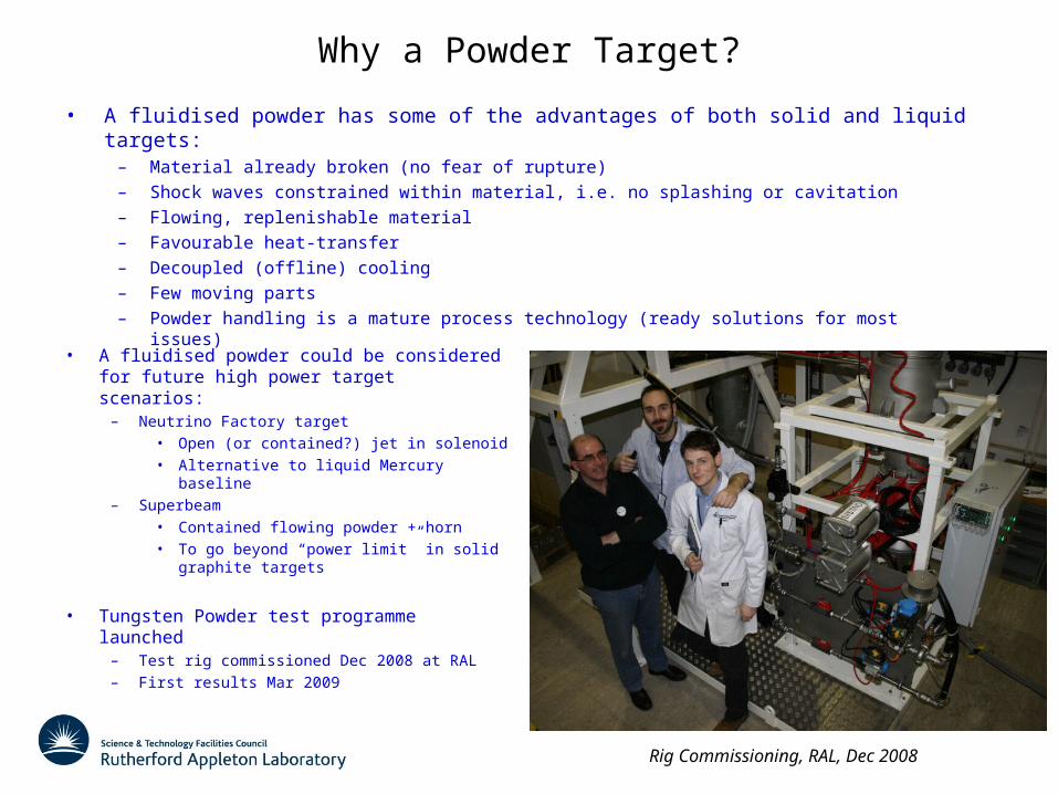
Rig Commissioning, RAL, Dec 2008
• A fluidised powder has some of the advantages of both solid and liquid targets:– Material already broken (no fear of rupture)– Shock waves constrained within material, i.e. no splashing or cavitation– Flowing, replenishable material– Favourable heat-transfer– Decoupled (offline) cooling– Few moving parts– Powder handling is a mature process technology (ready solutions for most issues)
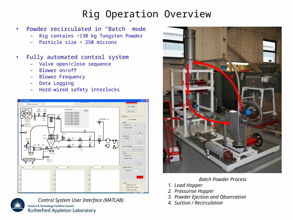
Rig Operation Overview• Powder recirculated in “Batch” mode
– Rig contains ~130 kg Tungsten Powder– Particle size < 250 microns
• Fully automated control system– Valve open/close sequence– Blower on/off– Blower Frequency– Data Logging– Hard-wired safety interlocks
Batch Powder Process1. Load Hopper2. Pressurise Hopper3. Powder Ejection and Observation4. Suction / RecirculationControl System User Interface (MATLAB)
1
2
3
4

Summary of Data runs 18 March – 01 April
• Total ~3,000 kg powder ejected– 31 suction/ejection cycles
• Parameters Varied:– Conveying pressure range 2 to 5 bar– Coaxial flow geometry– Coaxial flow velocity 10 – 30 m/s
• Powder jet recorded using High-speed camera– Vision Research PHANTOM 7.1– 5000 fps
• Rig instrumentation data logged throughout– Pressure– Flowrate– Temperature– Mass
High speed camera setup
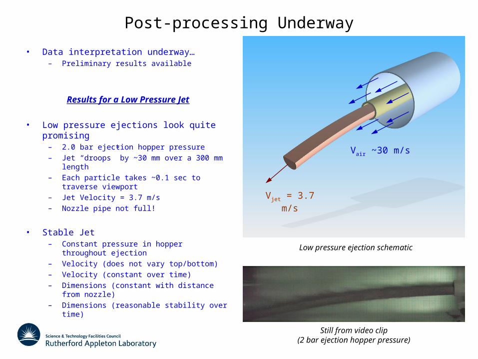
Post-processing Underway
• Data interpretation underway…– Preliminary results available
Results for a Low Pressure Jet
• Low pressure ejections look quite promising– 2.0 bar ejection hopper pressure– Jet “droops” by ~30 mm over a 300 mm length– Each particle takes ~0.1 sec to traverse
viewport– Jet Velocity = 3.7 m/s– Nozzle pipe not full!
• Stable Jet– Constant pressure in hopper throughout
ejection– Velocity (does not vary top/bottom)– Velocity (constant over time)– Dimensions (constant with distance from
nozzle)– Dimensions (reasonable stability over time)
Low pressure ejection schematic
Vjet = 3.7 m/s
Vair ~30 m/s
Still from video clip(2 bar ejection hopper pressure)

Video Clip
High-Speed Video Clip(2 bar ejection hopper pressure)
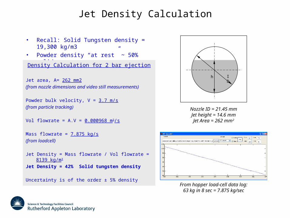
Jet Density Calculation
From hopper load-cell data log:63 kg in 8 sec = 7.875 kg/sec
h ID
Nozzle ID = 21.45 mmJet height = 14.6 mmJet Area = 262 mm2
• Recall: Solid Tungsten density = 19,300 kg/m3
• Powder density “at rest” ~ 50% solid
Density Calculation for 2 bar ejection
Jet area, A= 262 mm2
(from nozzle dimensions and video still measurements)
Powder bulk velocity, V = 3.7 m/s
(from particle tracking)
Vol flowrate = A.V = 0.000968 m3/s
Mass flowrate = 7.875 kg/s
(from loadcell)
Jet Density = Mass flowrate / Vol flowrate = 8139 kg/m3
Jet Density = 42% Solid tungsten density
Uncertainty is of the order ± 5% density

Summary
• Rig commissioning complete in 1st (simple) configuration
• Data runs Mar/Apr 2009
• Preliminary results indicate a jet density 42 ± 5 % is feasible– 42% Tungsten density is equivalent to 60% Mercury Density
Next Steps
• Ongoing evaluation of data runs
• Hardware– Reconfigure rig for vertical powder lift (without 90 degree bend
in suction line)– Install nozzle pressure sensors
• Experiments– Powder flotation, minimise velocity and wear in suction cycle– Nozzle pressure drop– Test minimum flow velocity (for contained powder target)
• Next EIP camera slot in June?
Suc
tion
Gra
vity
Next Configuration (vertical powder lift)
Recommended