FlexPod Datacenter with Oracle Real Application Clusters 12c Release 1 and NetApp All Flash FAS
Reference Architecture Business Processing Workloads Group, NetApp September 2016 | TR-4552
2 FlexPod Datacenter with Oracle Real Application Clusters 12c Release 1 and NetApp All Flash FAS Reference Architecture
© 2016 NetApp, Inc. All rights reserved.
TABLE OF CONTENTS
1 Executive Summary.............................................................................................................................. 5
1.1 FlexPod Program Benefits ..............................................................................................................................5
2 Solution Overview ................................................................................................................................ 6
2.1 Target Audience ..............................................................................................................................................6
2.2 Solution Technology .......................................................................................................................................7
2.3 Use Case Summary ........................................................................................................................................9
3 Technology Overview........................................................................................................................... 9
3.1 FlexPod ...........................................................................................................................................................9
3.2 Cisco Unified Computing System .................................................................................................................. 11
3.3 Cisco Nexus 9000 Series Switches .............................................................................................................. 15
3.4 NetApp AFF .................................................................................................................................................. 15
3.5 Oracle RAC 12c Release 1 ........................................................................................................................... 24
4 Technology Requirements ................................................................................................................ 24
4.1 Hardware Components ................................................................................................................................. 24
4.2 Software Components .................................................................................................................................. 25
5 Solution Design .................................................................................................................................. 26
5.1 Cisco Nexus Network Design ........................................................................................................................ 26
5.2 Cisco UCS Design ........................................................................................................................................ 28
5.3 NetApp AFF Storage Design......................................................................................................................... 31
5.4 Oracle RAC 12c Release 1 Design ............................................................................................................... 38
6 Solution Verification ........................................................................................................................... 39
6.1 Technology Requirements ............................................................................................................................ 40
6.2 Performance Validation ................................................................................................................................. 40
6.3 SnapCenter Validation .................................................................................................................................. 43
6.4 NetApp Storage System Plug-In for Oracle Enterprise Manager: Validation ................................................ 52
6.5 Resiliency Validation ..................................................................................................................................... 57
Conclusion ................................................................................................................................................ 59
Appendix .................................................................................................................................................... 60
Linux Kernel Parameter Settings .......................................................................................................................... 60
Oracle Parameter Settings ................................................................................................................................... 61
Best Practices ....................................................................................................................................................... 62
3 FlexPod Datacenter with Oracle Real Application Clusters 12c Release 1 and NetApp All Flash FAS Reference Architecture
© 2016 NetApp, Inc. All rights reserved.
Acknowledgements .................................................................................................................................. 63
References ................................................................................................................................................. 63
Cisco Unified Computing System ......................................................................................................................... 63
Cisco Nexus Networking ...................................................................................................................................... 63
NetApp FAS Storage ............................................................................................................................................ 63
NetApp SnapCenter ............................................................................................................................................. 64
NetApp Storage System Plug-In for Oracle Enterprise Manager .......................................................................... 64
Interoperability Matrixes ....................................................................................................................................... 64
Version History ......................................................................................................................................... 64
LIST OF TABLES
Table 1) Hardware components. .................................................................................................................................. 25
Table 2) Solution software components. ...................................................................................................................... 25
Table 3) NetApp AFF8000 storage system technical specifications. ............................................................................ 32
Table 4) Storage aggregate configuration. ................................................................................................................... 34
Table 5) Volume and LUN configuration....................................................................................................................... 35
Table 6) Supported storage types: SnapCenter Plug-In for Oracle. ............................................................................. 38
Table 7) Production Oracle RAC node configuration. ................................................................................................... 39
Table 8) Database LUN and volume configuration. ...................................................................................................... 41
Table 9) Validated database performance.................................................................................................................... 43
Table 10) Linux Kernel parameter settings. .................................................................................................................. 60
Table 11) Oracle Init.ora parameter settings. ............................................................................................................... 61
Table 12) Oracle 12c RAC on FlexPod best practices. ................................................................................................ 62
LIST OF FIGURES
Figure 1) FlexPod Datacenter solution component families. ..........................................................................................5
Figure 2) High-level solution architecture. ......................................................................................................................8
Figure 3) FCoE direct-connection topology. ................................................................................................................. 11
Figure 4) Cisco UCS components (graphic supplied by Cisco). ................................................................................... 12
Figure 5) ONTAP data management software. ............................................................................................................ 18
Figure 6) SnapCenter architecture. .............................................................................................................................. 21
Figure 7) Overall solution topology. .............................................................................................................................. 27
Figure 8) Cisco UCS backplane configurations: VIC 1340. .......................................................................................... 30
Figure 9) Server logic configuration. ............................................................................................................................. 31
Figure 10) ONTAP data management software in a SAN-only environment. ............................................................... 31
Figure 11) ONTAP data management software in a NAS-only environment. ............................................................... 32
Figure 12) Multipath HA to DS2246 SSD shelves. ....................................................................................................... 34
Figure 13) SnapCenter application plug-ins. ................................................................................................................ 37
4 FlexPod Datacenter with Oracle Real Application Clusters 12c Release 1 and NetApp All Flash FAS Reference Architecture
© 2016 NetApp, Inc. All rights reserved.
Figure 14) Row count of table testcf1. .......................................................................................................................... 43
Figure 15) Backup of dataset initiated. ......................................................................................................................... 44
Figure 16) Successful completion of backup. ............................................................................................................... 45
Figure 17) Table dropped. ............................................................................................................................................ 46
Figure 18) Choose a backup to restore. ....................................................................................................................... 47
Figure 19) Database recovery scope. .......................................................................................................................... 48
Figure 20) Successful completion of restore operation. ............................................................................................... 49
Figure 21) Table testcf1 restored. ................................................................................................................................ 50
Figure 22) List of databases (including two clones). ..................................................................................................... 51
Figure 23) Full functionality of database clone. ............................................................................................................ 52
Figure 24) Oracle Enterprise Manager NetApp performance summary page............................................................... 53
Figure 25) Oracle Enterprise Manager storage aggregate utilization report. ................................................................ 54
Figure 26) Oracle Enterprise Manager storage aggregate space utilization report. ..................................................... 54
Figure 27) Oracle Enterprise Manager volumes in aggregate report. ........................................................................... 55
Figure 28) Oracle Enterprise Manager aggregate space utilization in percentage report. ............................................ 55
Figure 29) Oracle Enterprise Manager cluster node overview report. .......................................................................... 56
Figure 30) Oracle Enterprise Manager SVM volumes and space utilization report. ..................................................... 57
Figure 31) IOPS during FCoE link failure test. .............................................................................................................. 58
Figure 32) Observed IOPS during controller failover test. ............................................................................................ 59
Figure 33) Observed IOPS during fabric interconnect failover test. .............................................................................. 59

5 FlexPod Datacenter with Oracle Real Application Clusters 12c Release 1 and NetApp All Flash FAS Reference Architecture
© 2016 NetApp, Inc. All rights reserved.
1 Executive Summary
This document describes a reference architecture for Oracle Real Application Clusters (RAC) 12c
Release 1 built on the NetApp® All Flash FAS (AFF) FlexPod® model. This solution includes Cisco UCS
B200 M4 and M3 blade servers and the NetApp AFF8080 EX storage array. The other major highlights of
this solution are the use of NetApp SnapCenter® enterprise software for application-integrated database
backup, recovery, and cloning; NetApp Storage System Plug-In for Oracle Enterprise Manager; and Cisco
Nexus 9000 series switches for client traffic.
This document also discusses design choices and best practices for this shared infrastructure platform.
These design considerations and recommendations are not limited to the specific components described
in this document and are also applicable to other versions.
1.1 FlexPod Program Benefits
FlexPod is a predesigned, best practices data center architecture that is built on the Cisco Unified
Computing System (Cisco UCS), the Cisco Nexus family of switches, and NetApp FAS and AFF systems.
FlexPod is a suitable platform for running a variety of virtualization hypervisors as well as bare-metal
operating systems (OSs) and enterprise workloads. FlexPod delivers a baseline configuration and can
also be sized and optimized to accommodate many different use cases and requirements. Figure 1
shows the FlexPod Datacenter solution component families.
Figure 1) FlexPod Datacenter solution component families.
6 FlexPod Datacenter with Oracle Real Application Clusters 12c Release 1 and NetApp All Flash FAS Reference Architecture
© 2016 NetApp, Inc. All rights reserved.
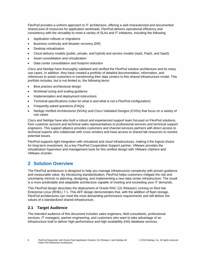
FlexPod provides a uniform approach to IT architecture, offering a well-characterized and documented
shared pool of resources for application workloads. FlexPod delivers operational efficiency and
consistency with the versatility to meet a variety of SLAs and IT initiatives, including the following:
Application rollouts or migrations
Business continuity and disaster recovery (DR)
Desktop virtualization
Cloud delivery models (public, private, and hybrid) and service models (IaaS, PaaS, and SaaS)
Asset consolidation and virtualization
Data center consolidation and footprint reduction
Cisco and NetApp have thoroughly validated and verified the FlexPod solution architecture and its many
use cases. In addition, they have created a portfolio of detailed documentation, information, and
references to assist customers in transforming their data centers to this shared infrastructure model. This
portfolio includes, but is not limited to, the following items:
Best practice architectural design
Workload sizing and scaling guidance
Implementation and deployment instructions
Technical specifications (rules for what is and what is not a FlexPod configuration)
Frequently asked questions (FAQs)
NetApp Verified Architectures (NVAs) and Cisco Validated Designs (CVDs) that focus on a variety of use cases
Cisco and NetApp have also built a robust and experienced support team focused on FlexPod solutions,
from customer account and technical sales representatives to professional services and technical support
engineers. This support alliance provides customers and channel services partners with direct access to
technical experts who collaborate with cross vendors and have access to shared lab resources to resolve
potential issues.
FlexPod supports tight integration with virtualized and cloud infrastructures, making it the logical choice
for long-term investment. As a key FlexPod Cooperative Support partner, VMware provides the
virtualization hypervisor and management tools for this verified design with VMware vSphere and
VMware vCenter.
2 Solution Overview
The FlexPod architecture is designed to help you manage infrastructure complexity with proven guidance
and measurable value. By introducing standardization, FlexPod helps customers mitigate the risk and
uncertainty intrinsic to planning, designing, and implementing a new data center infrastructure. The result
is a more predictable and adaptable architecture capable of meeting and exceeding your IT demands.
This FlexPod design describes the deployment of Oracle RAC 12c Release1 running on Red Hat
Enterprise Linux (RHEL) 7.1. This AFF design demonstrates that, with the addition of flash storage,
FlexPod architectures can meet the most demanding performance requirements and still deliver the
values of a standardized shared infrastructure.
2.1 Target Audience
The intended audience of this document includes sales engineers, field consultants, professional
services, IT managers, partner engineering, and customers who want to take advantage of an
infrastructure built to deliver high-performance and high availability (HA) database services.

7 FlexPod Datacenter with Oracle Real Application Clusters 12c Release 1 and NetApp All Flash FAS Reference Architecture
© 2016 NetApp, Inc. All rights reserved.
2.2 Solution Technology
The Oracle Database 12c R1 Enterprise Edition is the result of more than 30 years of innovation in the
area of relational database management. It provides industry-leading performance, scalability, security,
and reliability in meeting the business needs of critical enterprise applications.
Oracle RAC technology addresses the challenges of rapidly increasing amounts of data while continuing
to provide high performance. To accomplish this, Oracle RAC 12c Release 1 uses a scale-out model in
which multiple servers work in an active-active configuration to deliver high performance, scalability, and
availability.
In addition, Oracle Automatic Storage Management (ASM) provides an integrated clustered file system
with a rich set of volume-management features, including the following:
Automatic file and volume management
Performance of raw I/O
Automatic data distribution and balancing across storage
Mirroring
Another important feature of Oracle RAC 12c Release 1 is Oracle Enterprise Manager. Oracle Enterprise
Manager is integrated into Oracle’s product stack to provide management and automation support for
Oracle databases. With Oracle Enterprise Manager, both on-premises and cloud-based Oracle IT can be
monitored and managed from a single interface.
This solution is based on a 4-node Oracle RAC 12c Release1 database using Oracle ASM, running on
RHEL 7.1.
Figure 2 shows the high-level solution architecture, including the Oracle RAC instances and the
SnapCenter repository.

8 FlexPod Datacenter with Oracle Real Application Clusters 12c Release 1 and NetApp All Flash FAS Reference Architecture
© 2016 NetApp, Inc. All rights reserved.
Figure 2) High-level solution architecture.
This design enables you to leverage the processing bandwidth of four RHEL 7.1 servers to service online
transaction processing (OLTP) workloads on a single database, providing the scalability to avoid
processing bottlenecks. It also provides server redundancy in the event that one of the Oracle RAC nodes
becomes unavailable.
This solution uses a NetApp AFF8080 EX storage array, which provides the resources and functionality
for data storage, data protection, high-performance I/O, and backup and recovery. When FCoE is used,
LUNs are provisioned for use as both RHEL 7.1 OS boot disks and Oracle ASM disks for data storage.
By using this technology, Oracle RAC 12c Release 1 databases deliver excellent performance, and native
application integration using NetApp SnapCenter 1.1 enables seamless backup, recovery, and cloning.
The solution also uses the NetApp Oracle Enterprise Manager Plug-In version 12.1.0.3.1 to consolidate
information about Oracle on NetApp environments into the Oracle Enterprise Manager Cloud Control
Console, providing one interface to monitor both databases and NetApp storage systems.
Cisco UCS fabric interconnects and B-Series servers enhance this configuration by providing flexibility
and availability in the compute layer. Redundant hardware and software components eliminate single
9 FlexPod Datacenter with Oracle Real Application Clusters 12c Release 1 and NetApp All Flash FAS Reference Architecture
© 2016 NetApp, Inc. All rights reserved.
points of failure and make sure that data traffic is uninterrupted in the event of a component failure. Cisco
UCS Service profiles ease deployment and maintenance activities by creating consistent configurations
that are easily updated and can be moved between physical blades as needed for maintenance or
upgrades.
Cisco Nexus 9000 switches act as the access layer for the primary and secondary database
environments. Cisco Nexus 9396PX switches are deployed in pairs, and the Cisco UCS fabric
interconnects are connected with virtual port channels (vPCs) for maximum availability. Cisco Nexus 9000
switches provide 40Gb of switching capability and can participate in the Cisco Application Centric
Infrastructure (ACI). However, these switches do not support the FC or FCoE storage protocols. To
enable FCoE in this solution, storage controllers are connected directly to the Cisco UCS fabric
interconnects with redundant connections for each controller.
When combined into a complete infrastructure, this solution delivers the following benefits:
Tier 1 Oracle 12cR1 database performance on a standardized, shared infrastructure
Database-level availability by using Oracle RAC 12c Release 1
Integrated backup and recovery of Oracle RAC 12c Release 1 databases with SnapCenter software
Integrated cloning of databases for secondary processing or testing and development using SnapCenter software
Consolidated and automated monitoring of both Oracle and NetApp environments by Oracle Enterprise Manager, with results being accessible through the Oracle Enterprise Manager Cloud Control Console
Hardware-level redundancy for all of the major components by using Cisco UCS, Cisco Nexus, and NetApp availability features
2.3 Use Case Summary
The FlexPod Datacenter, Oracle RAC 12c, and NetApp AFF solution is designed to provide enterprises
with the performance, manageability, and reliability necessary for tier 1 application databases. The
following use cases have been configured and tested in the lab to demonstrate the performance and
functionality of this design:
Four-node Oracle RAC 12c database configuration, which generated 150,000 to 200,000 IOPS with an average read latency below 1ms for a typical OLTP workload
Unified monitoring of database and storage resources using Oracle Enterprise Manager with the NetApp Storage System Plug-In for Oracle Enterprise Manager
Backup and recovery of Oracle RAC 12c databases with NetApp SnapCenter 1.1 and the SnapCenter Plug-In for Oracle Database; backups were created while the database was online, causing no disruption in database availability
Cloning of Oracle RAC 12c databases with SnapCenter software for use in application testing and development environments
Failure testing of various infrastructure components while the environment is operating under a typical OLTP workload to verify the resiliency and reliability of the overall architecture
3 Technology Overview
3.1 FlexPod
FlexPod is a best practice data center architecture that includes three core components:
Cisco UCS
Cisco Nexus switches

10 FlexPod Datacenter with Oracle Real Application Clusters 12c Release 1 and NetApp All Flash FAS Reference Architecture
© 2016 NetApp, Inc. All rights reserved.
NetApp FAS and AFF systems
These components are connected and configured according to the best practices of both Cisco and
NetApp and provide the ideal platform for running a variety of enterprise workloads with confidence.
FlexPod can scale up for greater performance and capacity (adding compute, network, or storage
resources individually as needed). FlexPod can also scale out for environments that need multiple
consistent deployments (for example, rolling out additional FlexPod stacks). Although FlexPod delivers a
baseline configuration, it can also be flexibly sized and optimized to accommodate many different use
cases.
Typically, the more scalable and flexible a solution is, the more difficult it becomes to maintain a single
unified architecture capable of offering the same features and functionality across each implementation.
This is one of the key benefits of FlexPod. Each of the component families shown in Figure 3 offers
platform and resource options to scale the infrastructure up or down. They also support the same features
and functionality that are required by the configuration and connectivity best practices of FlexPod.
FlexPod addresses four primary design principles: application availability, scalability, flexibility, and
manageability. These architecture goals are as follows:
Application availability. Makes sure that services are accessible and ready to use.
Scalability. Addresses increasing demands with appropriate resources.
Flexibility. Provides new services or recovers resources without infrastructure modification requirements.
Manageability. Facilitates efficient infrastructure operations through open standards and APIs.
FlexPod: FCoE Direct-Connect Design
As noted previously, flexibility is a key design principle of FlexPod. Although the Cisco Nexus 9000 series
switches used in this design do not support FCP or FCoE, FlexPod can still support these protocols by
connecting unified target adapter (UTA) ports on the NetApp storage controllers directly to the Cisco UCS
fabric interconnects. This arrangement uses the FC features of the fabric interconnects to provide name
services and zoning capabilities. As a result, Cisco UCS servers can boot from and access FC or FCoE
storage without additional FC switches. Figure 3 shows the basic topology of this direct-connection
design.

11 FlexPod Datacenter with Oracle Real Application Clusters 12c Release 1 and NetApp All Flash FAS Reference Architecture
© 2016 NetApp, Inc. All rights reserved.
Figure 3) FCoE direct-connection topology.
3.2 Cisco Unified Computing System
The Cisco UCS is a next-generation data center platform that unites computing, networking, storage
access, and virtualization resources into a cohesive system designed to reduce the total cost of
ownership and increase business agility. The system integrates a low-latency, lossless 10 Gigabit
Ethernet (10GbE) unified network fabric with enterprise-class, x86-architecture servers. The system is an
integrated, scalable, multichassis platform in which all resources participate in a unified management
domain. Figure 4 shows an overview of Cisco UCS components.

12 FlexPod Datacenter with Oracle Real Application Clusters 12c Release 1 and NetApp All Flash FAS Reference Architecture
© 2016 NetApp, Inc. All rights reserved.
Figure 4) Cisco UCS components (graphic supplied by Cisco).
The main components of the Cisco UCS are as follows:
Compute. The system is based on an entirely new class of computing system that incorporates rack-mount and blade servers based on Intel Xeon 2600 v2 series processors.
Network. The system is integrated onto a low-latency, lossless, 10Gbps unified network fabric. This network foundation consolidates LANs, SANs, and high-performance computing networks that are typically configured as separate networks today. The unified fabric lowers costs by reducing the number of network adapters, switches, and cables and by reducing power and cooling requirements.
Virtualization. This system unleashes the full potential of virtualization by enhancing the scalability, performance, and operational control of virtual environments. Cisco security, policy enforcement, and diagnostic features are now extended into virtualized environments to better support changing business and IT requirements.
Storage access. The system provides consolidated access to both SAN storage and network-attached storage (NAS) over the unified fabric. By unifying storage access, the Cisco UCS can access storage over Ethernet (SMB 3.0 or iSCSI), FC, and FCoE. This provides customers with storage choices and investment protection. In addition, server administrators can preassign storage access policies to storage resources for simplified storage connectivity and management, which lead to increased productivity.
Management. The system integrates all system components so that the entire solution can be managed as a single entity by Cisco UCS Manager. Cisco UCS Manager has an intuitive GUI, a CLI, and a powerful scripting library module for Microsoft PowerShell built on a robust API. These different methods can manage all system configuration and operations.
Cisco UCS fuses access layer networking and servers. This high-performance, next-generation server
system provides a data center with a high degree of workload agility and scalability.
13 FlexPod Datacenter with Oracle Real Application Clusters 12c Release 1 and NetApp All Flash FAS Reference Architecture
© 2016 NetApp, Inc. All rights reserved.
Cisco UCS 6248UP Fabric Interconnects
The fabric interconnects provide a single point of connectivity and management for the entire system.
Typically deployed as an active-active pair, the system’s fabric interconnects integrate all components
into a single, highly available management domain controlled by Cisco UCS Manager. The fabric
interconnects manage all I/O efficiently and securely at a single point, resulting in deterministic I/O latency
independent of the topological location of a server or VM in the system.
Cisco UCS 6200 Series fabric interconnects support the system’s 10Gbps unified fabric with low-latency,
lossless, cut-through switching that supports IP, storage, and management traffic with a single set of
cables. The fabric interconnects feature virtual interfaces that terminate both physical and virtual
connections equivalently, establishing a virtualization-aware environment in which blades, rack servers,
and VMs are interconnected by the same mechanisms. The Cisco UCS 6248UP is a 1 rack unit (1RU)
fabric interconnect that features up to 48 universal ports that can support 10GbE, FCoE, or native FC
connectivity.
Cisco UCS 5108 Blade Server Chassis
The Cisco UCS 5100 Series blade server chassis is a crucial building block of the Cisco UCS, delivering
a scalable and flexible chassis. The Cisco UCS 5108 blade server chassis is 6RU high and can mount in
an industry-standard, 19-inch rack. A single chassis can house up to eight half-width Cisco UCS B-Series
blade servers and can accommodate both half-width and full-width blade form factors.
Four single-phase, hot-swappable power supplies are accessible from the front of the chassis. These
power supplies are 92% efficient and can be configured to support nonredundant configurations, N + 1
redundant configurations, and grid-redundant configurations. The rear of the chassis contains eight hot-
swappable fans, four power connectors (one per power supply), and two I/O bays for Cisco UCS 2200 XP
fabric extenders. A passive midplane provides up to 40Gbps of I/O bandwidth per server slot and up to
80Gbps of I/O bandwidth for two slots.
Cisco UCS 2204XP Fabric Extenders
The Cisco UCS 2204XP has four 10GbE, FCoE-capable, enhanced small form-factor pluggable (SFP+)
ports that connect the blade chassis to the fabric interconnect. Each Cisco UCS 2204XP has 16 x 10GbE
ports connected through the midplane to the half-width slot in the chassis. When configured in pairs for
redundancy, 2 x 2204XP fabric extenders provide up to 80Gbps to the chassis.
Cisco UCS B200 M4 Blade Servers
The enterprise-class Cisco UCS B200 M4 blade server extends the capabilities of the Cisco UCS portfolio
in a half-width blade form factor. The Cisco UCS B200 M4 is powered by the latest Intel Xeon E5-2600 v4
Series processor family CPUs. This server contains up to 1536GB of RAM (using 64GB DIMMs), two
solid-state drives (SSDs) or hard-disk drives (HDDs), and up to 80Gbps throughput connectivity. The
Cisco UCS B200 M4 blade server mounts in a Cisco UCS 5100 Series blade server chassis or a Cisco
UCS Mini blade server chassis. It supports one connector for Cisco’s Virtual Interface Card (VIC) 1340 or
VIC 1240 adapter, which provides Ethernet and FCoE.
Cisco VIC 1340
The Cisco UCS VIC 1340 is a 2-port 40Gbps Ethernet or dual 4 x 10Gbps Ethernet, FCoE-capable
modular LAN on motherboard (mLOM) designed exclusively for the M4 generation of Cisco UCS B-Series
blade servers. When used in combination with an optional port expander, the capabilities of the Cisco
UCS VIC 1340 are extended to two 40Gbps Ethernet ports.
The Cisco UCS VIC 1340 enables a policy-based, stateless, agile server infrastructure that can present
over 256 PCIe standards-compliant interfaces to the host. These interfaces can be dynamically
configured as either network interface cards (NICs) or host bus adapters (HBAs). In addition, the Cisco

14 FlexPod Datacenter with Oracle Real Application Clusters 12c Release 1 and NetApp All Flash FAS Reference Architecture
© 2016 NetApp, Inc. All rights reserved.
UCS VIC 1340 supports Cisco Data Center Virtual Machine Fabric Extender (VM-FEX) technology, which
extends the Cisco UCS fabric interconnect ports to VMs, simplifying server virtualization deployment and
management.
Cisco UCS Manager
Cisco UCS Manager provides unified, centralized, embedded management of all Cisco UCS software and
hardware components across multiple chassis and thousands of VMs. Administrators use this software to
manage the entire Cisco UCS as a single logical entity through an intuitive GUI, a CLI, or an XML API.
The Cisco UCS Manager resides on a pair of Cisco UCS 6200 Series fabric interconnects in a clustered,
active-standby configuration for HA. The software provides administrators with a single interface for
performing server provisioning, device discovery, inventory, configuration, diagnostics, monitoring, fault
detection, auditing, and statistics collection. Cisco UCS Manager service profiles and templates support
versatile role-based and policy-based management.
You can export system configuration information to configuration management databases to facilitate
processes based on IT Infrastructure Library (ITIL) concepts. Service profiles benefit both virtualized and
nonvirtualized environments. They increase the mobility of nonvirtualized servers, such as when you
move workloads from server to server or take a server offline for service or upgrade. You can also use
profiles in conjunction with virtualization clusters to bring new resources online easily, complementing
existing VM mobility.
Key elements managed by Cisco UCS Manager include the following:
Cisco UCS Integrated Management Controller (IMC) firmware
RAID controller firmware and settings
BIOS firmware and settings, including server universal user ID (UUID) and boot order
Converged network adapter firmware and settings, including MAC addresses, worldwide names (WWNs), and SAN boot settings
Virtual port groups used by VMs, with Cisco Data Center VM-FEX technology
Interconnect configuration, including uplink and downlink definitions, MAC address and WWN pinning, virtual local area networks (VLANs), virtual storage area networks, quality of service (QoS), bandwidth allocations, Cisco Data Center VM-FEX settings, and EtherChannels to upstream LAN switches
For more information, see the Cisco UCS Manager site.
A server’s identity is made up of many properties, including the UUID; the boot configuration; the BIOS
configuration; the number of NIC, MAC, and IP addresses; the number of HBAs; HBA WWNs; and so on.
Some of these parameters reside in the hardware of the server itself, including the BIOS firmware
version, the BIOS settings, the boot order, the FC boot settings, and so on. Other settings are kept on
your network and storage switches, such as VLAN assignments, FC fabric assignments, QoS settings,
ACLs, and so on. These configurations result in the following server deployment challenges:
The response to business needs is slow because of lengthy and tedious deployment processes.
Every deployment requires coordination between the server, storage, and network teams:
Firmware and settings for hardware components
Appropriate LAN and SAN connectivity
Settings tied to physical ports and adapter identities
Manual, error-prone processes that are difficult to automate
Complexity leads to higher opex costs:
Outages caused by human errors
Static infrastructure, leading to overprovisioning
15 FlexPod Datacenter with Oracle Real Application Clusters 12c Release 1 and NetApp All Flash FAS Reference Architecture
© 2016 NetApp, Inc. All rights reserved.
Complexity, which causes limited OS and application mobility
Cisco UCS has addressed these challenges with the introduction of service profiles, which enable
integrated, policy-based infrastructure management. Cisco UCS service profiles hold nearly all of the
configurable parameters that are required to set up a physical server. A set of user-defined policies
(rules) allows quick, consistent, repeatable, and secure deployments of Cisco UCS servers.
Cisco UCS service profiles contain values for a server's property settings, including virtual network
interface cards (vNICs), MAC addresses, boot policies, firmware policies, fabric connectivity, external
management, and high-availability information. When these settings are abstracted from the physical
server into a Cisco service profile, the service profile can then be deployed to any physical compute
hardware within the Cisco UCS domain. Furthermore, service profiles can be migrated at any time from
one physical server to another. This logical abstraction of the server personality removes dependency on
the hardware type or model and is a result of Cisco’s unified fabric model rather than the overlying
software tools on top.
Cisco is the only hardware provider to offer a truly unified management platform, with Cisco UCS service
profiles and hardware abstraction capabilities extending to both blade and rack servers. Some of the key
features and benefits of Cisco UCS service profiles are discussed in the following sections.
Service Profiles and Templates
Service profile templates are stored in the Cisco UCS 6200 Series fabric interconnects for reuse by
server, network, and storage administrators. Service profile templates consist of server requirements and
the associated LAN and SAN connectivity. Service profile templates allow different classes of resources
to be defined and applied to a number of resources, each with its own unique identities assigned from
predetermined pools.
Cisco UCS Manager can deploy a service profile on any physical server at any time. When a service
profile is deployed to a server, Cisco UCS Manager automatically configures the server, adapters, fabric
extenders, and fabric interconnects to match the configuration specified in the service profile. A service
profile template parameterizes the UUIDs that differentiate server instances.
This automation of device configuration reduces the number of manual steps required to configure
servers, NICs, HBAs, and LAN and SAN switches.
3.3 Cisco Nexus 9000 Series Switches
The Cisco Nexus 9000 Series delivers proven high performance, high density, low latency, and
exceptional power efficiency in a broad range of compact form factors. These switches, running in NX-OS
software mode, offer both modular and fixed 10/40/100GbE switch configurations with scalability up to
30Tbps of nonblocking performance. They provide less than 5-microsecond latency; 1,152 x 10Gbps or
288 x 40Gbps nonblocking layer 2 and layer 3 Ethernet ports; and wire-speed VXLAN gateway, bridging,
and routing support.
The Cisco Nexus 9396X switch delivers comprehensive line-rate layer 2 and layer 3 features in a 2RU
form factor. It supports line-rate 1/10/40GbE with 960Gbps of switching capacity. It is ideal for top-of-rack
and middle-of-row deployments in both traditional and Cisco ACI-enabled enterprise, service provider,
and cloud environments.
For more information, see the Cisco Nexus 9000 Series Switch product page.
3.4 NetApp AFF
Built on more than 20 years of innovation, ONTAP data management software has evolved to meet the
changing needs of customers and help drive their success. ONTAP software provides a rich set of data
management features and clustering for scale-out, operational efficiency, and nondisruptive operations to
offer customers one of the most compelling value propositions in the industry. The IT landscape is

16 FlexPod Datacenter with Oracle Real Application Clusters 12c Release 1 and NetApp All Flash FAS Reference Architecture
© 2016 NetApp, Inc. All rights reserved.
undergoing a fundamental shift to IT as a service (ITaaS). This model requires a pool of compute,
network, and storage to serve a wide range of applications and deliver a wide range of services.
Innovations such as ONTAP® data management software are fueling this revolution.
NetApp storage systems offer a completely unified storage architecture. The term unified refers to a
family of storage systems that simultaneously support SAN and NAS across many operating
environments, including VMware, Windows, Linux, and UNIX. This single architecture provides access to
data by using industry-standard protocols, including NFS, CIFS, iSCSI, FCP, and FCoE. Connectivity
options include standard Ethernet (10/100/1000 or 10GbE), FCoE (10Gb), and native FC (2, 4, 8, or
16Gbps).
This FlexPod Datacenter solution includes the NetApp AFF8000 series unified scale-out storage system.
Powered by NetApp clustered Data ONTAP® 8.3.1, the AFF8000 series unifies the SAN and NAS
storage infrastructure with the performance of SSD. The AFF8000 features a multiprocessor Intel chipset
and leverages high-performance memory modules, NVRAM to accelerate and optimize writes, and an
I/O-tuned PCIe gen3 architecture that maximizes application throughput. The AFF8000 series comes with
integrated UTA2 ports that support 16Gb FC, 10GbE, and FCoE.
If your storage requirements change over time, NetApp storage provides you with the flexibility to change
quickly without expensive and disruptive forklift upgrades. For example, a LUN can be changed from FC
access to iSCSI access without moving or copying data. Only a simple dismount of the FC LUN and a
mount of the same LUN with iSCSI are required. In addition, a single copy of data can be shared between
Windows and UNIX systems while allowing each environment to access the data through native protocols
and applications.
NetApp storage solutions provide redundancy and fault tolerance through clustered storage controllers;
hot-swappable redundant components such as cooling fans, power supplies, disk drives, and shelves;
and multiple network interfaces. This highly available and flexible architecture enables customers to
manage all data under one common infrastructure and achieve their mission requirements. The NetApp
unified storage architecture allows data storage with higher availability and performance, easier dynamic
expansion, and easier management than with any other solution.
Outstanding Performance
The NetApp AFF solution shares the same unified storage architecture, ONTAP data management
software, management interface, rich data services, and advanced feature set as the rest of the FAS
product families. The unique combination of all-flash media with ONTAP software delivers the consistent
low latency and high IOPS of all-flash storage with the industry-leading capabilities of the ONTAP data
management software. This combination offers proven enterprise availability, reliability, and scalability;
storage efficiency proven in thousands of deployments; unified storage with multiprotocol access;
advanced data services; and operational agility through tight application integration.
Enhancing Flash
ONTAP data management software has been leveraging flash technologies since 2009 and has
supported SSDs since 2010. This relatively long experience in dealing with SSDs has allowed NetApp to
tune ONTAP features to optimize SSD performance and enhance flash media endurance.
ONTAP FlashEssentials is the power behind the performance and efficiency of AFF. ONTAP is a well-
known data management software tool, but it is not widely known that ONTAP software with the WAFL®
(Write Anywhere File Layout) file system is natively optimized for flash media.
ONTAP and WAFL include the following key features to optimize SSD performance and endurance:
NetApp storage efficiency technologies deliver space savings of up to tenfold or more. Features include inline compression, deduplication, and thin provisioning. Savings can be further increased by using NetApp Snapshot® and NetApp FlexClone® technologies.

17 FlexPod Datacenter with Oracle Real Application Clusters 12c Release 1 and NetApp All Flash FAS Reference Architecture
© 2016 NetApp, Inc. All rights reserved.
Multiple writes are coalesced and written as a unit. The resulting reduction in storage overhead during write workloads improves performance and flash media longevity.
AFF systems include a flash-optimized I/O path to maximize performance in a pure flash environment.
With advanced drive partitioning, SSDs can be shared among controllers, increasing usable capacity and allowing more flexibility in configuration.
AFF controllers can be used within a larger ONTAP cluster, enabling nondisruptive workload migration between the flash and hybrid tiers.
QoS capability safeguards service-level objectives in multiworkload and multitenant environments.
The parallelism built into ONTAP data management software, combined with multicore CPUs and large
system memories in the NetApp AFF8000 storage controllers, takes full advantage of SSD performance.
With the media optimizations built into ONTAP software, NetApp provides up to a five-year warranty with
all SSDs with no restrictions on the number of drive writes.
NetApp ONTAP
With ONTAP data management software, NetApp provides enterprise-ready, unified scale-out storage.
Developed from a solid foundation of proven ONTAP technology and innovation, ONTAP data
management software is the basis for large virtualized shared storage infrastructures that are architected
for nondisruptive operations over the lifetime of the system. Controller nodes are deployed in HA pairs
that participate in a single storage domain or cluster.
NetApp ONTAP scale-out is one way to respond to growth in a storage environment. All storage
controllers have physical limits to their expandability. The number of CPUs, memory slots, and space for
disk shelves dictates the maximum capacity and controller performance. If more storage or performance
capacity is needed, it might be possible to add CPUs and memory or install additional disk shelves, but
ultimately the controller becomes completely populated, with no further expansion possible. At this stage,
the only option is to acquire another controller.
If the original controller must be completely replaced by a newer and larger controller, data migration is
required to transfer the data from the old controller to the new one. This process is time consuming and
potentially disruptive and most likely requires configuration changes on all of the attached host systems.
If the newer controller can coexist with the original controller, you now have two storage controllers that
must be individually managed, and there are no native tools that can balance or reassign workloads
across them. The situation becomes even more difficult as the number of controllers increases. If the
scale-up approach is used, the operational burden increases consistently as the environment grows, and
the end result is a very unbalanced and difficult-to-manage environment. Technology refresh cycles
require substantial planning in advance, lengthy outages, and configuration changes, which introduce risk
into the system.
Scale-Out
In contrast, the use of scale-out means that as the storage environment grows, additional controllers are
added seamlessly to the resource pool residing on a shared storage infrastructure. Host and client
connections as well as datastores can move seamlessly and nondisruptively anywhere in the resource
pool. Therefore, existing workloads can be easily balanced over the available resources, and new
workloads can be easily deployed. Technology refreshes (replacing disk shelves or adding or completely
replacing storage controllers) are accomplished in an environment that remains online and continues
serving data.
The benefits of scale-out include the following:
Nondisruptive operations
The ability to add additional workloads with no effect on existing services

18 FlexPod Datacenter with Oracle Real Application Clusters 12c Release 1 and NetApp All Flash FAS Reference Architecture
© 2016 NetApp, Inc. All rights reserved.
Operational simplicity and flexibility
Although scale-out products have been available for some time, these products were typically subject to
one or more of the following shortcomings:
Limited protocol support (NAS only)
Limited hardware support (supported only a particular type of storage controller or a very limited set)
Little or no storage efficiency (thin provisioning, deduplication, and compression)
Little or no data replication capability
Therefore, although these products are well positioned for certain specialized workloads, they are less
flexible, less capable, and not robust enough for broad deployment throughout the enterprise.
As is depicted in Figure 5, NetApp ONTAP data management software is the first product to offer a
complete scale-out solution with an adaptable, always-available storage infrastructure for today’s highly
virtualized environment. An ONTAP system can scale up to 24 nodes, depending on platform and
protocol, and can contain different disk types and controller models in the same storage cluster.
Figure 5) ONTAP data management software.
Nondisruptive Operations
The move to shared infrastructure has made it nearly impossible to schedule downtime for routine
maintenance. ONTAP data management software is designed to eliminate the planned downtime needed
for maintenance operations and lifecycle operations as well as unplanned downtime caused by hardware
and software failures.
Three standard tools make this elimination of downtime possible:
NetApp DataMotion™ for Volumes (vol move) allows data volumes to be moved from one aggregate to another on the same or a different cluster node.
Logical interface (LIF) migrate allows the physical Ethernet interfaces in ONTAP to be virtualized. LIF migrate also allows LIFs to be moved from one network port to another on the same or a different cluster node.
Aggregate relocate (ARL) allows complete aggregates to be transferred from one controller in an HA pair to the other without data movement.
Used individually and in combination, these tools allow you to nondisruptively perform a wide range of
operations, from moving a volume from a faster to a slower disk all the way up to a complete controller
and storage technology refresh.
19 FlexPod Datacenter with Oracle Real Application Clusters 12c Release 1 and NetApp All Flash FAS Reference Architecture
© 2016 NetApp, Inc. All rights reserved.
As storage nodes are added to the system, all physical resources—including CPUs, cache memory,
network I/O bandwidth, and disk I/O bandwidth—can be easily kept in balance. NetApp clustered Data
ONTAP 8.3.1 enables you to perform the following tasks:
Add or remove storage shelves (over 23PB in an 8-node cluster and up to 69PB in a 24-node cluster)
Move data between storage controllers and tiers of storage without disrupting users and applications
Dynamically assign, promote, and retire storage, while providing continuous access to data as administrators upgrade or replace storage
These capabilities allow administrators to increase capacity while balancing workloads and can reduce or
eliminate storage I/O hot spots without the need to remount shares, modify client settings, or stop running
applications.
Availability
Shared storage infrastructure can provide services to thousands of VMs. In such environments, downtime
is not an option. The NetApp AFF solution eliminates sources of downtime and protects critical data
against disaster with two key features:
HA. A NetApp HA pair provides seamless failover to its partner in the case of hardware failure. Each of the two identical storage controllers in an HA pair serves data independently during normal operation. During an individual storage controller failure, the data service process is transferred from the failed storage controller to the surviving partner.
NetApp RAID DP® data protection technology. During any virtualized server deployment, data protection is critical because RAID failures can affect hundreds of servers, resulting in lost productivity. RAID DP provides performance comparable to that of RAID 10, yet it requires fewer disks to achieve equivalent protection. RAID DP provides protection against double disk failure, in contrast to RAID 5, which can protect against only one disk failure per RAID group. RAID DP in effect provides RAID 10 performance and protection at a RAID 5 price point.
NetApp Advanced Data Management Capabilities
This section describes the storage efficiencies, multiprotocol support, VMware integrations, and
replication capabilities of the NetApp AFF solution.
Storage Efficiencies
Storage efficiency enables you to store the maximum amount of data within the smallest possible space
at the lowest possible cost. The following NetApp storage efficiency technologies can help you to realize
maximum space savings:
Inline compression. Data compression reduces the disk space required, regardless of storage protocol, application, or storage tier. Inline compression also reduces the data that must be moved to SSDs, thereby reducing wear on SSDs.
Inline zero elimination and always-on deduplication. Data deduplication cuts storage requirements by reducing redundancies in primary, backup, and archival data. Inline deduplication of zeros speeds up VM provisioning by 20% to 30%. Combined with always-on deduplication running at all times, this deduplication method provides more space savings than postprocess deduplication.
Snapshot technology. NetApp Snapshot technology provides low-cost, instantaneous, point-in-time copies of the file system (volume) or LUN by preserving the ONTAP architecture and WAFL consistency points without affecting performance. NetApp SnapCenter integrates with the Oracle ASM interface to create application-consistent Snapshot copies of production-level Oracle databases with no downtime for the production database.
Thin provisioning. Thin provisioning, implemented by NetApp at the NetApp FlexVol® volume level and at the LUN level, defers storage purchases by keeping a common pool of free storage available to all applications.

20 FlexPod Datacenter with Oracle Real Application Clusters 12c Release 1 and NetApp All Flash FAS Reference Architecture
© 2016 NetApp, Inc. All rights reserved.
Thin replication. Thin replication is at the center of the NetApp data protection software portfolio, which includes NetApp SnapMirror® and NetApp SnapVault® software. SnapVault thin replication enables more frequent backups that use less storage capacity because no redundant data is moved or stored. SnapMirror thin replication protects business-critical data while minimizing storage capacity requirements.
RAID DP. RAID DP technology protects against double disk failure without sacrificing performance or adding disk-mirroring overhead.
FlexClone volumes. FlexClone virtual cloning reduces the need for storage by creating multiple, instant, space-efficient, writable copies.
Advanced Storage Features
NetApp ONTAP data management software provides a number of additional features leverageable in an
Oracle database environment whether for the infrastructure supporting the database servers or for the
database servers themselves. These features include the following:
NetApp Snapshot copies. Manual or automatically scheduled point-in-time copies that write only changed blocks, with no performance penalty. Snapshot copies consume minimal storage space because only changes to the active file system are written. Individual files and directories can easily be recovered from any Snapshot copy, and the entire volume can be restored back to any Snapshot state in seconds.
Compression. Compression of data blocks on disk to provide space savings instead of or in addition to savings obtained with deduplication.
LIF. A logical interface that is associated with a physical port, an interface group (ifgrp), or a VLAN interface. More than one LIF can be associated with a physical port at the same time. There are three types of LIFs: NFS LIFs, iSCSI LIFs, and FC LIFs.
LIFs are logical network entities that have the same characteristics as physical network devices but are not tied to physical objects. LIFs used for Ethernet traffic are assigned specific Ethernet-based details such as IP addresses and iSCSI qualified names and are then associated with a specific physical port capable of supporting Ethernet. LIFs used for FC-based traffic are assigned specific FC-based details such as worldwide port names (WWPNs) and are then associated with a specific physical port capable of supporting FC or FCoE. NAS LIFs can be nondisruptively migrated to any other physical network port throughout the entire cluster at any time, either manually or automatically (by using policies). SAN LIFs rely on multipath input/output and asymmetric logical unit access (ALUA) to notify clients of any changes in the network topology.
Storage virtual machines (SVMs). An SVM is a secure virtual storage server that contains data volumes and one or more LIFs through which it serves data to clients. An SVM securely isolates the shared virtualized data storage and network and appears as a single dedicated server to its clients. Each SVM has a separate administrator authentication domain and can be managed independently by an SVM administrator.
Multiprotocol Support
By supporting all common NAS and SAN protocols on a single platform, NetApp unified storage enables
the following:
Direct access to storage by each client
Network file sharing across different platforms
Simple and fast data storage and data access for all client systems
Fewer storage systems
Greater efficiency from each deployed system

21 FlexPod Datacenter with Oracle Real Application Clusters 12c Release 1 and NetApp All Flash FAS Reference Architecture
© 2016 NetApp, Inc. All rights reserved.
ONTAP data management software can support several protocols concurrently in the same storage
system. Unified storage is important to all VMware vSphere solutions, such as CIFS/SMB for user data,
NFS or SAN for the VM datastores, and guest-connect iSCSI LUNs for Windows applications.
The following protocols are supported:
NFS v3, v4, and v4.1 (including pNFS)
iSCSI
FC
FCoE
CIFS
NetApp SnapCenter
NetApp SnapCenter software is a unified, scalable platform for application-consistent data protection and
clone management. SnapCenter simplifies backup, restore, and clone lifecycle management with
application-integrated workflows. With storage-based data management, SnapCenter enables increased
performance and availability and reduced testing and development times.
Simple
NetApp SnapCenter includes both the SnapCenter Server and individual lightweight application,
database, and OS plug-ins, which are all controlled from a central management console. The SnapCenter
Server is actually able to push the relevant SnapCenter plug-ins to the appropriate database hosts. The
management console delivers a consistent user experience across all applications and databases. It
incorporates a single GUI to support critical functions, such as job monitoring, event notification, logging,
dashboard, reporting, scheduling, and policy management for all application and database plug-ins.
SnapCenter Figure 6 depicts the SnapCenter architecture.
Figure 6) SnapCenter architecture.

22 FlexPod Datacenter with Oracle Real Application Clusters 12c Release 1 and NetApp All Flash FAS Reference Architecture
© 2016 NetApp, Inc. All rights reserved.
SnapCenter Server also includes Snapshot catalog management to facilitate easy rollback to point-in-
time copies. SnapCenter Server checks application, database, and OS interoperability and then
nondisruptively installs and upgrades software plug-ins on application and database hosts. Those plug-
ins can then be managed from the central management console.
In addition, SnapCenter Server allows you to run custom scripts either before or after common operations
such as backup, cloning, and restore by using Perl, Python, or PowerShell.
Scalable
SnapCenter is designed with ease of use in mind, with the added ability to scale capacity and
performance to meet the needs of large enterprises. You can transparently add SnapCenter Servers to
address requirements for HA and load balancing, with support for thousands of applications and
databases. By adding another SnapCenter Server or multiple servers, you can protect against any one
server failing. Therefore, you can add multiple servers to increase resiliency, and they are all managed as
a single server. The added servers also increase the level of performance for your backup infrastructure
because performance is transparently balanced across servers.
Backup and restore performance is also increased by leveraging the onboard capabilities of NetApp
storage-based Snapshot copies. Offloading this functionality not only simplifies operation, but also
offloads Snapshot functions from the host.
By leveraging the embedded functionality of the NetApp ONTAP platform to perform space-efficient
FlexClone management, SnapCenter also improves the performance of testing and development.
Application, database, and virtual infrastructure administrators can initiate FlexClone volumes
independently of storage administrators through the same GUI console. The self-service feature of space-
efficient cloning reduces testing and development time and puts more capability into the hands of
application owners.
Empowering
IT organizations face the challenge of providing self-service capabilities to individual administrators while
also retaining oversight and control of the storage infrastructure by the storage administrator. SnapCenter
uses role-based access control to delegate functionality to application and database owners while
retaining oversight and control by a central storage infrastructure administrator. This level of control and
security frees storage administrators from tedious tasks that application and database owners can do for
themselves. At the same time, it protects the overall infrastructure from bullying applications or from
infrastructure abuse from even the best-intended colleagues.
As IT organizations continue to grow with the size of the overall business, IT specialists play an important
role in the data center. SnapCenter provides application-specific or database-specific workflows tailored
to meet the needs of application, database, and virtualization infrastructure administrators. Because each
application or database has a unique workflow, application and database owners should find that their
delegated workflows are familiar and well suited to their use models.
SnapCenter is also built to be open by offering REST APIs for the integration of third-party orchestration
and cloud management software.
Administrators can use the SnapCenter plug-ins for applications and databases so that the application or
database is consistent at all levels, which promotes maximum recoverability. Plug-ins for SnapCenter
allow a variety of restore capabilities. They can roll forward logs and enable application or database
administrators to clone or recover to the latest information available or to a specific point in time.
SnapCenter also leverages NetApp storage-based backup and replication functions, such as SnapVault
and SnapMirror. All SnapCenter plug-ins can perform cloning and restore operations from both primary
and secondary locations.
23 FlexPod Datacenter with Oracle Real Application Clusters 12c Release 1 and NetApp All Flash FAS Reference Architecture
© 2016 NetApp, Inc. All rights reserved.
SnapCenter Plug-In for Oracle Database
Some of the key features for SnapCenter plug-in for Oracle Database include backup, verification,
restore, recovery, and clone of Oracle Database 11g R2 and 12cR1:
Standalone
RAC
ASM
Data guard and active data guard configurations
Virtualized Oracle databases running on VMware (raw device mapping [RDM] LUNs and virtual machine disks [VMDKs]), through integration with NetApp Virtual Storage Console (VSC) version 6.2
NFS, DNFS, and SAN protocols with NetApp ONTAP data management software
Databases running under applications on Linux, including SAP
Running on Linux:
RHEL
Oracle Linux
SUSE Linux
Support for Oracle Database 12c R1 multitenant option
Container database backup
Restoration of entire container database or individual pluggable databases
Automatic discovery of Oracle databases on a host
Advanced Oracle RAC awareness
Cloud and hybrid cloud integration
NetApp Private Storage
NetApp Cloud ONTAP®
NetApp Storage System Plug-In for Oracle Enterprise Manager
The NetApp Storage System Plug-In for Oracle Enterprise Manager adds NetApp storage monitoring
capabilities to Oracle Enterprise Manager. With the plug-in, NetApp storage systems can be monitored
from the same single interface from which Oracle resources are managed and monitored.
Plug-In Features
Deploying the plug-in in an Oracle Cloud Control environment provides the following management
features for NetApp storage systems:
Comprehensive availability and performance monitoring
Detailed information about NetApp storage capacity, volumes, and Snapshot copies
Graphical information about CIFS and NFS protocols, network load, and CPU statistics
Configuration information about NetApp storage products, licenses, and disks
Consolidated information about NetApp storage and Oracle database in the form of a database to NetApp storage mapping report
Comparison of configuration management information and generation of differential data reports
Alerts and violations based on thresholds set for the monitored data
Availability and Performance Metrics
The following NetApp storage component availability and performance metrics are collected:
Spare disks and failed disks

24 FlexPod Datacenter with Oracle Real Application Clusters 12c Release 1 and NetApp All Flash FAS Reference Architecture
© 2016 NetApp, Inc. All rights reserved.
Storage node capacity metrics for all volumes and for the overall storage node
RAID configuration
Volume allocation details
Aggregate usage details
Network interface statistics
CIFS and NFS operations
Storage controller CPU utilization
SnapMirror settings and status
Space reserved and available for Snapshot copies
System load
Configuration Metrics
The following NetApp storage component configuration information is collected by the SnapCenter Plug-
In for Oracle Database:
NetApp storage controller product information, including model, firmware version, and vendor
NetApp license information
Disk summary for the NetApp storage system
3.5 Oracle RAC 12c Release 1
The Oracle Database 12c Enterprise Edition provides industry-leading performance, scalability, security,
and reliability on clustered or single servers with a wide range of options to meet the business needs of
critical enterprise applications. Oracle RAC 12c Release 1 brings an innovative approach to the
challenges of rapidly increasing amounts of data and demand for high performance. Oracle RAC uses a
scale-out model in which active-active clusters use multiple servers to deliver high performance,
scalability, and availability.
Oracle ASM provides an integrated cluster file system and volume-management features that remove the
need for third-party volume management tools and reduce the complexity of the overall architecture.
Some of the key Oracle ASM features include:
Automatic file and volume management
Database file system with performance of raw I/O
Automatic distribution and striping of data
A choice of external (array-based) data protection, two-way, and three-way mirror protection
Control over which copy of mirrored data should be used preferentially
With these capabilities, Oracle ASM provides an alternative to the third-party file system and volume-
management solutions for database storage management tasks, such as creating or laying out databases
and managing the use of disk space. Oracle ASM provides load balancing of I/O across all LUNs or files
in an Oracle ASM disk group by distributing the contents of each data file evenly across the entire pool of
storage in the disk group.
4 Technology Requirements
4.1 Hardware Components
Table 1 lists the hardware components used to validate the solution. The hardware components used in
any particular implementation of the solution might vary based on customer requirements.

25 FlexPod Datacenter with Oracle Real Application Clusters 12c Release 1 and NetApp All Flash FAS Reference Architecture
© 2016 NetApp, Inc. All rights reserved.
Table 1) Hardware components.
Hardware Configuration
Cisco UCS 6200 Series fabric interconnects
2 x Cisco UCS 6248UP fabric interconnects
Includes Cisco UCS Manager
Cisco UCS B200 M4 4 x blades, each equipped with:
2 x Intel Xeon CPU E5-2630 v3 at 2.40GHz (8 cores each)
128GB RAM
1 x VIC 1340
Used as Oracle RAC nodes
Cisco UCS B200 M3 2 x blades, each equipped with:
2 x Intel Xeon CPU E5-2650 0 at 2.00GHz (8 cores/each)
96GB RAM
1 x VIC 1340
Used as workload generator and SnapCenter Servers
Cisco UCS 5108 chassis Includes 2 x Cisco UCS-IOM 2204XP
Cisco Nexus 9396PX No expansion modules
NetApp AFF8080 EX 2 x controllers, HA
NetApp DS2246 disk shelves 2 x disk shelves, one per controller
SSD 1.6TB 24 x SSDs per DS2246 shelf (48 total)
4.2 Software Components
Table 2 lists the software components used to implement the solution. The software components used in
any particular implementation of the solution might vary based on customer requirements.
Table 2) Solution software components.
Software/Firmware Version
Compute
Cisco UCS Manager 2.2(5b)
Networking
Cisco Nexus 9396PX NX-OS software release 7.0(3)I1(3)
Storage
NetApp clustered Data ONTAP 8.3.1
NetApp System Manager 8.3.1
NetApp SnapCenter Server 1.1
SnapCenter Plug-In for UNIX 1.1
SnapCenter Plug-In for Oracle Database 1.1
26 FlexPod Datacenter with Oracle Real Application Clusters 12c Release 1 and NetApp All Flash FAS Reference Architecture
© 2016 NetApp, Inc. All rights reserved.
Software/Firmware Version
Database Server
RHEL 7.1
Oracle Database 12cR1 12.1.0.2.0
Oracle Enterprise Manager Cloud control 13c Release 1 for Linux x86-64 13.1.0.0
NetApp Storage System Plug-In for Oracle Enterprise Manager software 12.1.0.3.1
SLOB (Silly Little Oracle Benchmark)
https://my.syncplicity.com/share/ize90aqgqy9yj1d/2015.07.16.slob_2.3.0.3-1.tar
2.3.0.3-1
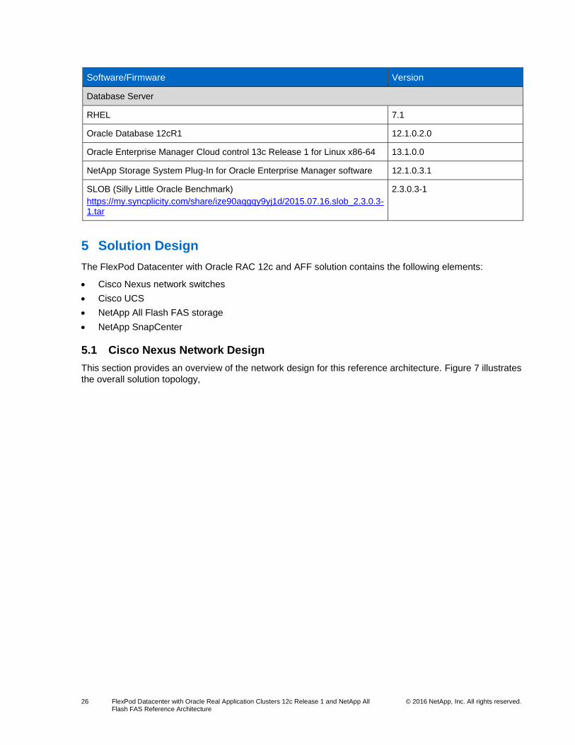
5 Solution Design
The FlexPod Datacenter with Oracle RAC 12c and AFF solution contains the following elements:
Cisco Nexus network switches
Cisco UCS
NetApp All Flash FAS storage
NetApp SnapCenter
5.1 Cisco Nexus Network Design
This section provides an overview of the network design for this reference architecture. Figure 7 illustrates
the overall solution topology,

27 FlexPod Datacenter with Oracle Real Application Clusters 12c Release 1 and NetApp All Flash FAS Reference Architecture
© 2016 NetApp, Inc. All rights reserved.
Figure 7) Overall solution topology.
Network Design Overview
As seen in Figure 7, Cisco Nexus 9396PX switches serve as the access layer for the Oracle RAC
database instances. The Cisco UCS fabric interconnects and storage systems are connected to the Cisco
Nexus 9000 access switches with vPCs for maximum availability. FCoE connectivity is provided by direct
links between the storage controllers and fabric interconnects. For this validation, a single pair of Cisco
Nexus switches was used.
Network Switching
Two Cisco Nexus 9396PX switches running NX-OS software release 7.0(3)I1(3) were used in this
solution design. These switches were chosen because of their 10/40GbE switching capability and their
ability to participate in Cisco ACI networks. Other Cisco Nexus 9000 switches can be used depending on
port count requirements, or additional pairs could be added to extend the pod even further.
The switches are configured as vPC peers. vPCs are used to provide switch-level redundancy to the
Cisco UCS fabric interconnects and AFF systems without requiring special configuration on those
devices. The switches in this solution are operating in NX-OS mode but could also be configured as
leaves in an ACI network.
Although Cisco Nexus 9000 series switches do not support FC or FCoE, FlexPod systems using these
switches can still support these protocols. FCoE links from the storage array are directly connected to the
Cisco UCS fabric interconnects operating in FC switch mode. Ports from each controller are connected to

28 FlexPod Datacenter with Oracle Real Application Clusters 12c Release 1 and NetApp All Flash FAS Reference Architecture
© 2016 NetApp, Inc. All rights reserved.
each fabric interconnect, and zoning is performed on the fabric interconnects to provide an industry-
standard, dual-fabric SAN topology.
Host Server Networking
As seen in Figure 7, the service profile for each Cisco UCS B200 blade is configured with two virtual FC
ports and two virtual Ethernet ports. Four of the blades use FCoE to boot up as RHEL 7.1 hosts from the
AFF8080 EX storage array as well as accessing LUNs for Oracle database storage. In the same way,
another blade boots RHEL 7.1 and is used as the workload application server, while another blade boots
Windows Server 2012 R2, for use as the SnapCenter Server. For Ethernet access, all hosts are
configured with one standard vSwitch with two uplink ports that use originating port ID load balancing.
Storage Networking
All storage traffic in this reference architecture uses FCoE. Each controller is connected with one FCoE
link directly to each fabric interconnect, providing four paths from the hosts to the storage. FCoE ports
operate independently, with ALUA providing multipathing and load balancing, and initiator groups
(igroups) on the storage system mapping the appropriate LUNs to each Linux host. FCoE bandwidth can
be increased in this topology by adding additional FCoE links between the controllers and fabric
interconnects.
For Ethernet traffic, each controller is connected to both Cisco Nexus 9396PX switches by using two
ports in a multimode LACP interface group on the controller and vPCs across both switches. FlexPod
specifications require Ethernet connectivity for storage even if the primary storage protocol is FC/FCoE to
provide flexibility for the overall architecture. For example, during this validation, temporary NFS
datastores were used to store ISO images and other static data files due to the ease of use and the
flexibility of the connections.
5.2 Cisco UCS Design
The FlexPod design simultaneously supports both B-Series and C-Series deployments. This section of
the document discusses only the integration and design of B-Series deployments into FlexPod.
Cisco UCS: B-Series Server and Fabric Interconnect Design
The Cisco UCS supports the virtual server environment by providing a robust, highly available, and
extremely manageable compute resource. In this solution, Cisco UCS 6248UP fabric interconnects are
the foundation of the Cisco UCS. Cisco UCS 5108 blade chassis with 2204XP IOM-FEX modules are
used to support B200-M4/M3 blades with VIC 1340 adapters. Each I/O module (IOM) is connected to its
respective fabric interconnect with 4 x 10GbE unified fabric links. The fabric interconnects are connected
to the Cisco Nexus 9396PX switches for Ethernet connectivity and directly to the NetApp AFF8080 EX
storage arrays by using FCoE for storage access. Figure 9 shows the Ethernet and FCoE connectivity of
the Oracle servers and SnapCenter Server.
Cisco UCS Fabric Interconnect Connectivity
As seen in Figure 7, the FlexPod FCoE direct-attach topology supports any storage protocol a customer
might want to use. As is typical of all FlexPod architectures, fabric interconnects are connected to the
FlexPod Ethernet switches with port channels and vPCs. On each fabric interconnect, two 10GbE ports
are configured as uplink ports and port channels.
One port is connected to each 9396PX 10GbE switch. The switch ports are configured as vPCs, providing
both link-level and switch-level redundancy for traffic to each fabric interconnect. Additional 10GbE ports
can be added to the port channel uplinks to increase network bandwidth to the blades as needed.
For SAN connectivity, the fabric interconnects are connected directly to the AFF8080 EX storage array.
For this validation, each fabric interconnect has one 10Gb FCoE link to each storage controller. We

29 FlexPod Datacenter with Oracle Real Application Clusters 12c Release 1 and NetApp All Flash FAS Reference Architecture
© 2016 NetApp, Inc. All rights reserved.
created a dual-fabric SAN topology because there are no data links between the fabric interconnects and
the vHBAs configured on each blade map to one FI or the other. As with network bandwidth, FCoE
bandwidth can be increased by adding additional links, although the four FCoE links in use were not used
significantly during the workload testing of this architecture.
To support the FCoE storage port type, you must configure the fabric interconnects for FC switch mode,
which requires a reboot of the fabric interconnect to take effect. FC switch mode enables the fabric
interconnect to perform some FC switch functions, such as name services and zoning. After the fabric
interconnect is in FC switch mode, two ports on each fabric interconnect are configured as FCoE storage
ports, and each fabric interconnect is connected to each controller. This effectively creates an industry-
standard, dual-fabric SAN topology that uses the fabric interconnect as FC switches. Additional links to
each storage controller can be added to increase the available bandwidth. Zoning in this configuration is
managed through the storage connection policies created in Cisco UCS Manager and applied to the
service profiles and/or templates. These policies define the set of storage target ports to which a given
vHBA is zoned.
A balanced and predictable fabric is critical within any data center environment. As designed, the FlexPod
system accommodates a myriad of traffic types (vMotion, NFS, FCoE, control traffic, and so on) and is
capable of absorbing traffic spikes and protecting against traffic loss. Cisco UCS and Cisco Nexus QoS
system classes and policies deliver this functionality. In this solution verification effort, the FlexPod
system was configured to support jumbo frames with an MTU size of 9,000. Enabling jumbo frames
allows the FlexPod environment to optimize throughput between devices while simultaneously reducing
the consumption of CPU resources. This class was assigned to the best effort class. With regard to jumbo
frames, you must make sure that MTU settings are applied uniformly across the stack to prevent
fragmentation and negative performance implications that inconsistent MTUs can introduce.
Cisco UCS 5108 Chassis Connectivity
FlexPod allows organizations to adjust the individual components of the system to meet their particular
scale or performance requirements. One key design decision in the Cisco UCS domain is the selection of
I/O components. There are numerous combinations of I/O adapter, Cisco UCS Extenders IOM, and Cisco
UCS fabric interconnect available. Therefore, you should understand the effect that these selections have
on the overall flexibility, scalability, and resiliency of the fabric.
Figure 8 illustrates the available backplane connections in the Cisco UCS 5100 series chassis as tested
in this solution. Each of the two Cisco UCS 2204XP Series fabric extenders installed in each blade
chassis has four 10GbE, FCoE-capable, SFP+ ports that connect the blade chassis to the fabric
interconnect. Each 2204XP fabric extender also has four 10GBASE KR (802.3ap) standardized Ethernet
backplane paths available for connection to each half-width blade slot. Two paths go to the mLOM slot,
and two go to the mezzanine card slot. This solution was tested with 2204XP FEX modules, VIC 1340
mLOM cards without expansion ports, and no mezzanine cards. Each blade was provisioned with 20Gb
of available bandwidth shared between Ethernet and FCoE traffic. To increase the bandwidth available to
each blade, the 2208XP IOM can be installed along with other Cisco UCS adapter card options to
increase the available bandwidth to 80Gb per half-width blade.
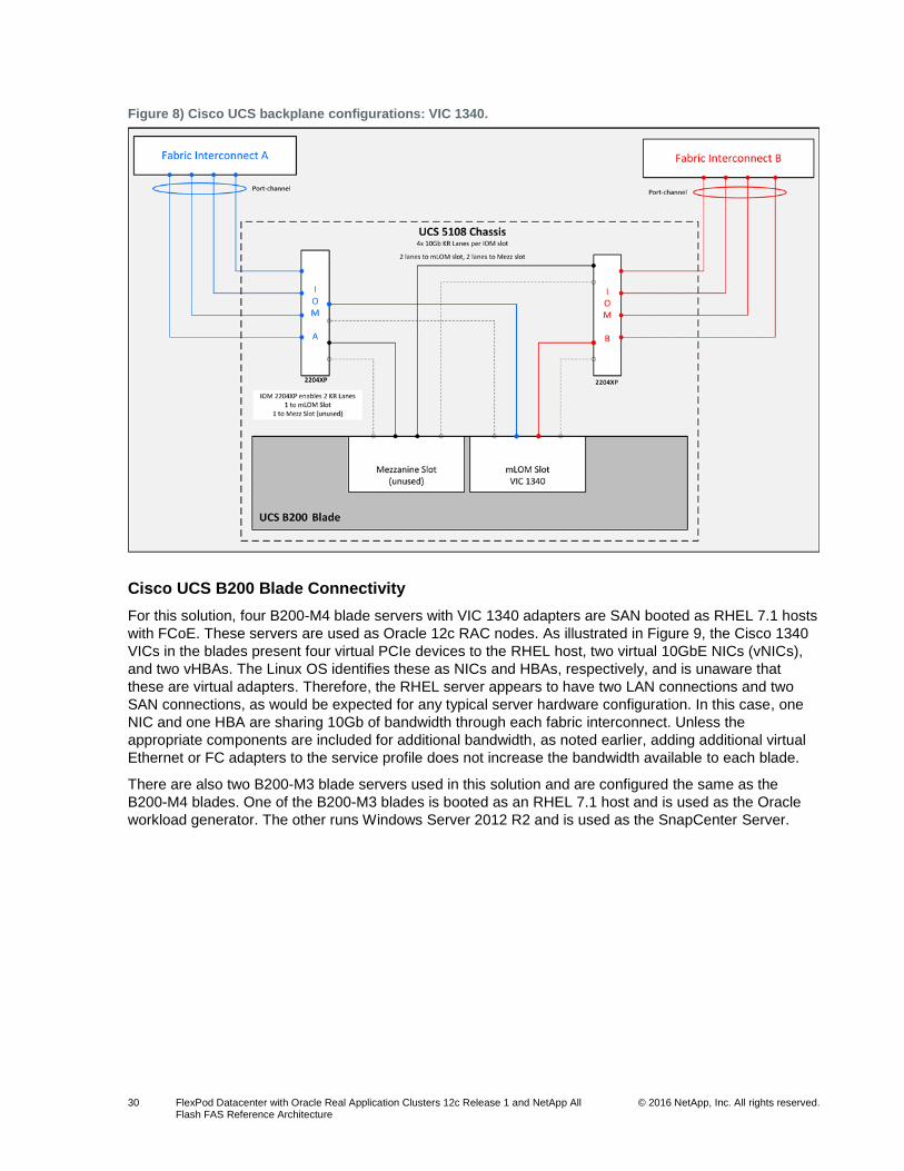
30 FlexPod Datacenter with Oracle Real Application Clusters 12c Release 1 and NetApp All Flash FAS Reference Architecture
© 2016 NetApp, Inc. All rights reserved.
Figure 8) Cisco UCS backplane configurations: VIC 1340.
Cisco UCS B200 Blade Connectivity
For this solution, four B200-M4 blade servers with VIC 1340 adapters are SAN booted as RHEL 7.1 hosts
with FCoE. These servers are used as Oracle 12c RAC nodes. As illustrated in Figure 9, the Cisco 1340
VICs in the blades present four virtual PCIe devices to the RHEL host, two virtual 10GbE NICs (vNICs),
and two vHBAs. The Linux OS identifies these as NICs and HBAs, respectively, and is unaware that
these are virtual adapters. Therefore, the RHEL server appears to have two LAN connections and two
SAN connections, as would be expected for any typical server hardware configuration. In this case, one
NIC and one HBA are sharing 10Gb of bandwidth through each fabric interconnect. Unless the
appropriate components are included for additional bandwidth, as noted earlier, adding additional virtual
Ethernet or FC adapters to the service profile does not increase the bandwidth available to each blade.
There are also two B200-M3 blade servers used in this solution and are configured the same as the
B200-M4 blades. One of the B200-M3 blades is booted as an RHEL 7.1 host and is used as the Oracle
workload generator. The other runs Windows Server 2012 R2 and is used as the SnapCenter Server.
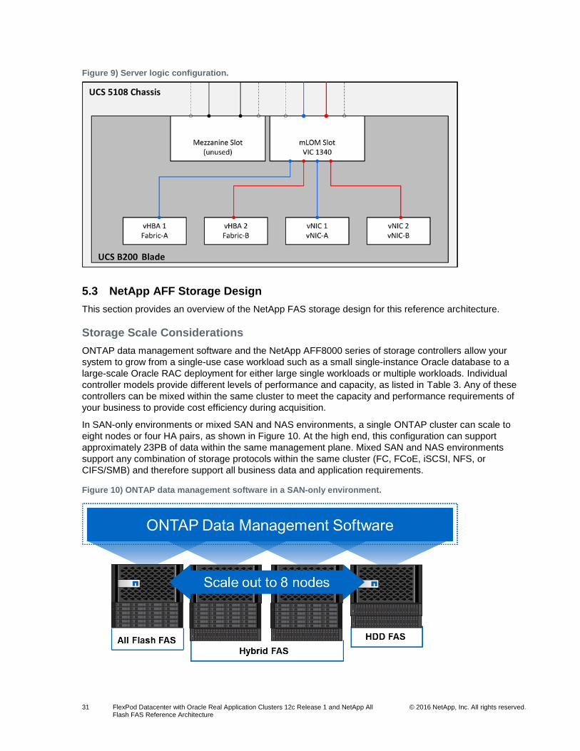
31 FlexPod Datacenter with Oracle Real Application Clusters 12c Release 1 and NetApp All Flash FAS Reference Architecture
© 2016 NetApp, Inc. All rights reserved.
Figure 9) Server logic configuration.
5.3 NetApp AFF Storage Design
This section provides an overview of the NetApp FAS storage design for this reference architecture.
Storage Scale Considerations
ONTAP data management software and the NetApp AFF8000 series of storage controllers allow your
system to grow from a single-use case workload such as a small single-instance Oracle database to a
large-scale Oracle RAC deployment for either large single workloads or multiple workloads. Individual
controller models provide different levels of performance and capacity, as listed in Table 3. Any of these
controllers can be mixed within the same cluster to meet the capacity and performance requirements of
your business to provide cost efficiency during acquisition.
In SAN-only environments or mixed SAN and NAS environments, a single ONTAP cluster can scale to
eight nodes or four HA pairs, as shown in Figure 10. At the high end, this configuration can support
approximately 23PB of data within the same management plane. Mixed SAN and NAS environments
support any combination of storage protocols within the same cluster (FC, FCoE, iSCSI, NFS, or
CIFS/SMB) and therefore support all business data and application requirements.
Figure 10) ONTAP data management software in a SAN-only environment.

32 FlexPod Datacenter with Oracle Real Application Clusters 12c Release 1 and NetApp All Flash FAS Reference Architecture
© 2016 NetApp, Inc. All rights reserved.
In NAS-only environments, a single ONTAP cluster can scale up to 24 nodes or 12 HA pairs, as shown in
Figure 11. At the high end, this configuration supports approximately 69PB of data within the same
management plane. NAS environments can take advantage of NFS and CIFS/SMB storage protocols,
providing support for both business file data, virtualization data, and Oracle databases.
Figure 11) ONTAP data management software in a NAS-only environment.
In addition to scale, separate clusters provide an additional level of fault isolation, disparate management
domains, and support for multiple geographic locations. At this time, individual clusters are bound to
individual sites, though cross-cluster (intercluster) replication is supported for any geographic distance.
In this reference architecture, a single cluster was used, with data for the Oracle RAC database being
spread evenly across both storage nodes. This provided the highest level of performance and resiliency
for the overall solution. This environment supports additional controllers and/or workloads, and the
storage cluster can scale as workload requirements demand.
NetApp AFF8000 Technical Specifications
Table 3 provides the technical specifications for the four NetApp AFF series storage controllers:
AFF8020, AFF8040, AFF8060, and AFF8080 EX.
Note: All data in this table applies to active-active, dual-controller configurations.
Table 3) NetApp AFF8000 storage system technical specifications.
AFF8080 EX AFF8060 AFF8040 AFF8020
Maximum SSD 240 240 240 240
Maximum raw capacity: all flash
384TB/349TiB 384TB/349TiB 384TB/349TiB 384TB/349TiB
Effective capacity 1565.3TB/1423TiB 1565.3TB/1423TiB 1565.3TB/1423TiB 1565.3TB/1423TiB
Controller form factor
Dual-enclosure HA
2 controllers and 2 x IOXMs in 2 x 6U chassis
Total of 12U or single-enclosure HA
2 controllers in single 6U chassis
Dual-enclosure HA
2 controllers and 2 IOXMs in two 6U chassis
Total of 12U or single-enclosure HA
2 controllers in single 6U chassis
Single-enclosure HA
2 controllers in single 6U chassis
Single-enclosure HA
2 controllers in single 3U chassis

33 FlexPod Datacenter with Oracle Real Application Clusters 12c Release 1 and NetApp All Flash FAS Reference Architecture
© 2016 NetApp, Inc. All rights reserved.
AFF8080 EX AFF8060 AFF8040 AFF8020
Memory 256GB 128GB 64GB 48GB
NVRAM 32GB 16GB 16GB 8GB
PCIe expansion slots
6 or 24 8 or 24 8 4
Onboard I/O: UTA2 (10GbE/FCoE, 16Gb FC)
8 8 8 4
Onboard I/O: 10GbE
8 8 8 4
Onboard I/O: GbE 8 8 8 4
Onboard I/O: 6Gb SAS
8 8 8 4
Storage networking supported
FC, FCoE, iSCSI, NFS, pNFS, and CIFS/SMB
OS version Data ONTAP 8.3 or later; Data ONTAP 8.3.1 or later for AFF8080 EX single-chassis HA
Storage Network Connectivity
NetApp AFF systems with ONTAP data management software can support almost any storage protocol in
use today. FlexPod architectures support this flexibility throughout the infrastructure; therefore, you can
choose the option most appropriate for your application or environment.
For this solution, primary storage access is provided by FCoE. UTA2 ports on each storage controller are
connected directly to each Cisco UCS fabric interconnect. The fabric interconnects operate in FC switch
mode with no connectivity between them in a typical dual-fabric SAN topology. Zoning and name services
are provided by the fabric interconnect to control FC host access to the storage targets. While this
topology only supports access by hosts connected to the attached fabric interconnects, you can connect
additional ports to other Cisco UCS fabric interconnects or other FC SAN switches. Alternatively,
additional ports can be added to the existing fabric interconnects to increase the available FCoE
bandwidth.
Although FCoE provides primary storage access in this solution, each storage controller is also
connected to the Cisco Nexus 9396PX network switches. Two ports on each controller are configured as
an LACP ifgroup, with one port connected to each switch. The switch ports are configured as vPCs to
provide switch-level resiliency on top of the link-level redundancy provided by the ifgroup. This network
uplink can be used to support NFS connectivity to Oracle databases (including support for the Oracle
Direct NFS client), user home directories, or other CIFS shares or iSCSI access for other servers or
applications. As with FCoE, additional 10GbE links can be added to the ifgroup to increase the available
network bandwidth as required.
Back-End Storage Connectivity Overview
Figure 12 illustrates the connectivity between the AFF8080 EX storage controllers and the DS2246 disk
shelves for both primary and secondary storage systems. Each AFF8080 EX controller is 6RU, and each
DS2246 is 2RU, so the primary and secondary systems occupy 16RU each.

34 FlexPod Datacenter with Oracle Real Application Clusters 12c Release 1 and NetApp All Flash FAS Reference Architecture
© 2016 NetApp, Inc. All rights reserved.
Figure 12) Multipath HA to DS2246 SSD shelves.
Disk Assignment
To maximize the SSD performance on AFF systems, the disks should be assigned to the controllers in a
way that is different from the default ONTAP disk assignment. As seen in Figure 12, each controller has
four SAS loops connected to the disk shelves. The default behavior of ONTAP is to assign an entire disk
shelf to each controller, which provides two SAS connections from the active controller to 24 disks (A and
D to 24 disks in shelf 1). By assigning half of the disks in each shelf to each controller, each controller has
four SAS connections to 24 disks (A and D to 12 disks in shelf 1, B and C to 12 disks in shelf 2), providing
additional bandwidth between the disks and controllers.
Aggregate, LUN, and Volume Configuration
AFF systems support NetApp advanced disk partitioning, which allows drives to be partitioned and then
shared between root aggregates and data aggregates. This avoids duplication of parity drives and
maximizes the usable capacity of the available SSDs. This process is done by dividing the disks into two
partitions: a small partition used to build root aggregate RAID groups and a larger partition used to build
data aggregate RAID groups. In this configuration with 24 SSDs per controller, 23 data partitions are used
to build one data aggregate per controller, with one spare drive on each. Table 4 shows the storage
aggregate configuration used in this solution.
Table 4) Storage aggregate configuration.
Storage Aggregate Name Volume Name
Vol Size (GB)
Description
Fvl1-8080-01 Aggr1_node01 Advanced drive partitioning
21 data partitions + 2 parity partitions
RAID DP total aggregate size = 27TB
1 spare drive
Aggr0_fvl1_8080_01_0 Root 348GB Total aggregate size = 368GB
Fvl1-8080-02 Aggr1_node02 Advanced drive partitioning
21 data partitions + 2 parity partitions
RAID DP total aggregate size = 27TB
1 spare drive

35 FlexPod Datacenter with Oracle Real Application Clusters 12c Release 1 and NetApp All Flash FAS Reference Architecture
© 2016 NetApp, Inc. All rights reserved.
Storage Aggregate Name Volume Name
Vol Size (GB)
Description
Aggr0_fvl1_8080_02_0 Root 348GB Total aggregate size = 368GB
It is a NetApp best practice to create a dedicated FlexVol volume for each LUN, unless LUN data is
expected to be fairly static and could benefit from volume-level storage efficiencies such as deduplication.
For OS (Linux and Windows Server) boot LUNs, NetApp created a single volume with several LUNs
because the LUNs were small in size, did not change often, deduplicated well, and did not require
granular Snapshot copies or replication.
Due to their size, comparatively lower level of I/O, and the Oracle ASM I/O balancing behavior, one-to-
one LUN to volume mapping was not necessary. Two redo log LUNs were created per volume with one
volume on each storage node. Also, due to the static nature of archive logs, LUNs for the flash recovery
area were also created with multiple LUNs to a single volume, one volume per storage node.
For data LUNs, individual volumes were created with only a single LUN in each volume. This
configuration allows granular management of Snapshot and replication schedules, and it is a requirement
for using SnapCenter to back up, clone, and restore Oracle databases. To support the Oracle grid
infrastructure, two voting LUNs were created, one LUN to a volume with one volume on each controller.
All database LUNs were created for use as Oracle ASM disks in ASM disk groups, with ASM balancing
storage and I/O across all LUNs in each disk group. Table 5 shows the volumes and LUNs that were
used during testing of this solution.
Table 5) Volume and LUN configuration.
Aggregate Name
Volume Name Vol Size (GB) LUN Name LUN Size (GB)
Mount Point/Description
Fvl1-8080-01 Boot01 618GB Lun01 200GB Linux boot LUN
Fvl1-8080-01 Boot02 618GB Lun02 200GB Linux boot LUN
Fvl1-8080-01 Boot03 618GB Lun03 200GB Linux boot LUN
Fvl1-8080-02 Boot04 618GB Lun04 200GB Linux boot LUN
Fvl1-8080-02 Boot05 618GB Lun05 200GB Linux boot LUN
Fvl1-8080-02 Boot06 618GB Lun06 200GB Windows Server boot LUN
Fvl1-8080-01 Data01 2110GB Lun_data_01 2048GB Oracle data LUN
Fvl1-8080-01 Data02 2110GB Lun_data_02 2048GB Oracle data LUN
Fvl1-8080-01 Data03 2110GB Lun_data_03 2048GB Oracle data LUN
Fvl1-8080-01 Data04 2110GB Lun_data_04 2048GB Oracle data LUN
Fvl1-8080-02 Data05 2110GB Lun_data_05 2048GB Oracle data LUN
Fvl1-8080-02 Data06 2110GB Lun_data_06 2048GB Oracle data LUN
Fvl1-8080-02 Data07 2110GB Lun_data_07 2048GB Oracle data LUN
Fvl1-8080-02 Data08 2110GB Lun_data_08 2048GB Oracle data LUN
Fvl1-8080-01 Redo01 164GB Lun_redo_01
Lun_redo_02
80GB
80GB
Redo log LUN
Redo log LUN
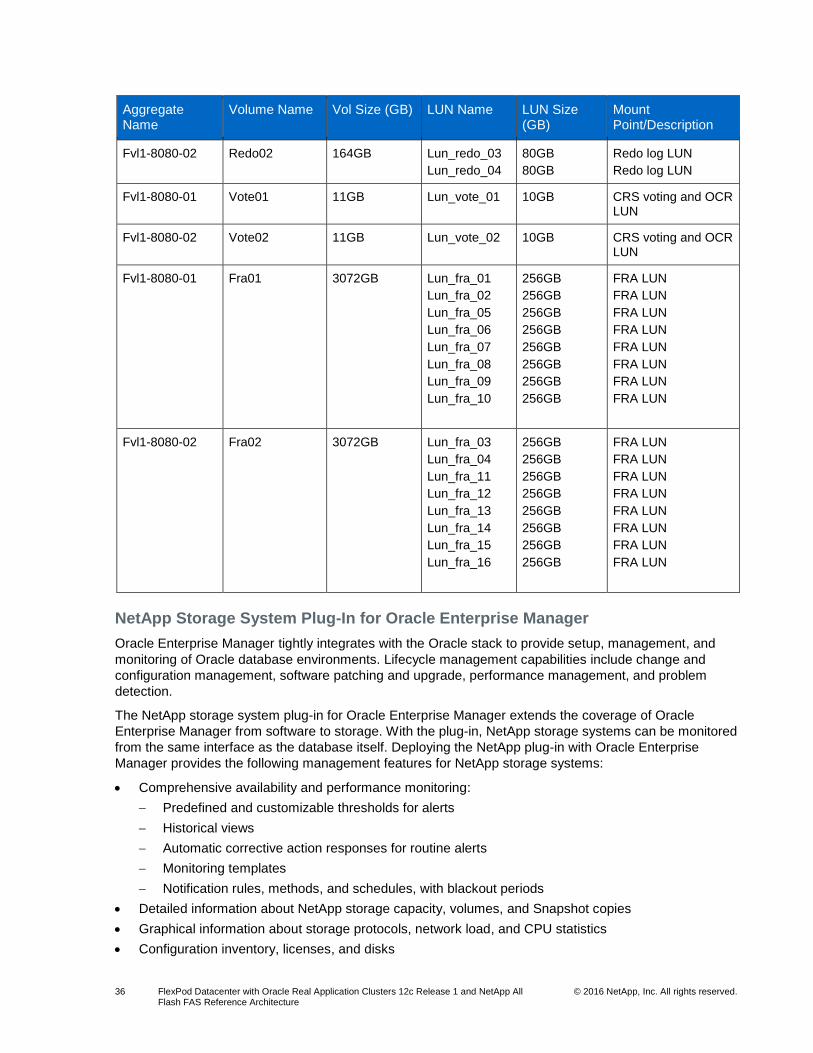
36 FlexPod Datacenter with Oracle Real Application Clusters 12c Release 1 and NetApp All Flash FAS Reference Architecture
© 2016 NetApp, Inc. All rights reserved.
Aggregate Name
Volume Name Vol Size (GB) LUN Name LUN Size (GB)
Mount Point/Description
Fvl1-8080-02 Redo02 164GB Lun_redo_03
Lun_redo_04
80GB
80GB
Redo log LUN
Redo log LUN
Fvl1-8080-01 Vote01 11GB Lun_vote_01 10GB CRS voting and OCR LUN
Fvl1-8080-02 Vote02 11GB Lun_vote_02 10GB CRS voting and OCR LUN
Fvl1-8080-01 Fra01 3072GB Lun_fra_01
Lun_fra_02
Lun_fra_05
Lun_fra_06
Lun_fra_07
Lun_fra_08
Lun_fra_09
Lun_fra_10
256GB
256GB
256GB
256GB
256GB
256GB
256GB
256GB
FRA LUN
FRA LUN
FRA LUN
FRA LUN
FRA LUN
FRA LUN
FRA LUN
FRA LUN
Fvl1-8080-02 Fra02 3072GB Lun_fra_03
Lun_fra_04
Lun_fra_11
Lun_fra_12
Lun_fra_13
Lun_fra_14
Lun_fra_15
Lun_fra_16
256GB
256GB
256GB
256GB
256GB
256GB
256GB
256GB
FRA LUN
FRA LUN
FRA LUN
FRA LUN
FRA LUN
FRA LUN
FRA LUN
FRA LUN
NetApp Storage System Plug-In for Oracle Enterprise Manager
Oracle Enterprise Manager tightly integrates with the Oracle stack to provide setup, management, and
monitoring of Oracle database environments. Lifecycle management capabilities include change and
configuration management, software patching and upgrade, performance management, and problem
detection.
The NetApp storage system plug-in for Oracle Enterprise Manager extends the coverage of Oracle
Enterprise Manager from software to storage. With the plug-in, NetApp storage systems can be monitored
from the same interface as the database itself. Deploying the NetApp plug-in with Oracle Enterprise
Manager provides the following management features for NetApp storage systems:
Comprehensive availability and performance monitoring:
Predefined and customizable thresholds for alerts
Historical views
Automatic corrective action responses for routine alerts
Monitoring templates
Notification rules, methods, and schedules, with blackout periods
Detailed information about NetApp storage capacity, volumes, and Snapshot copies
Graphical information about storage protocols, network load, and CPU statistics
Configuration inventory, licenses, and disks
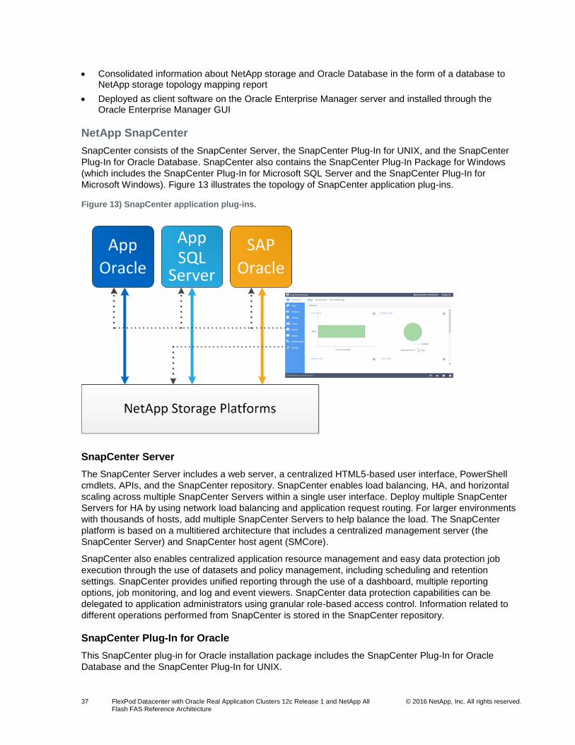
37 FlexPod Datacenter with Oracle Real Application Clusters 12c Release 1 and NetApp All Flash FAS Reference Architecture
© 2016 NetApp, Inc. All rights reserved.
Consolidated information about NetApp storage and Oracle Database in the form of a database to NetApp storage topology mapping report
Deployed as client software on the Oracle Enterprise Manager server and installed through the Oracle Enterprise Manager GUI
NetApp SnapCenter
SnapCenter consists of the SnapCenter Server, the SnapCenter Plug-In for UNIX, and the SnapCenter
Plug-In for Oracle Database. SnapCenter also contains the SnapCenter Plug-In Package for Windows
(which includes the SnapCenter Plug-In for Microsoft SQL Server and the SnapCenter Plug-In for
Microsoft Windows). Figure 13 illustrates the topology of SnapCenter application plug-ins.
Figure 13) SnapCenter application plug-ins.
SnapCenter Server
The SnapCenter Server includes a web server, a centralized HTML5-based user interface, PowerShell
cmdlets, APIs, and the SnapCenter repository. SnapCenter enables load balancing, HA, and horizontal
scaling across multiple SnapCenter Servers within a single user interface. Deploy multiple SnapCenter
Servers for HA by using network load balancing and application request routing. For larger environments
with thousands of hosts, add multiple SnapCenter Servers to help balance the load. The SnapCenter
platform is based on a multitiered architecture that includes a centralized management server (the
SnapCenter Server) and SnapCenter host agent (SMCore).
SnapCenter also enables centralized application resource management and easy data protection job
execution through the use of datasets and policy management, including scheduling and retention
settings. SnapCenter provides unified reporting through the use of a dashboard, multiple reporting
options, job monitoring, and log and event viewers. SnapCenter data protection capabilities can be
delegated to application administrators using granular role-based access control. Information related to
different operations performed from SnapCenter is stored in the SnapCenter repository.
SnapCenter Plug-In for Oracle
This SnapCenter plug-in for Oracle installation package includes the SnapCenter Plug-In for Oracle
Database and the SnapCenter Plug-In for UNIX.

38 FlexPod Datacenter with Oracle Real Application Clusters 12c Release 1 and NetApp All Flash FAS Reference Architecture
© 2016 NetApp, Inc. All rights reserved.
SnapCenter Plug-In for Oracle Database
The plug-in for Oracle is a host-side component of the NetApp integrated storage solution, offering
application-aware backup management of Oracle databases. With the plug-in for Oracle installed on the
Oracle host, SnapCenter automates backup, restore, recovery, verify, mount, unmount, and clone
operations.
SnapCenter fully supports Oracle databases that are on VMDKs or RDMs. The user experience in
SnapCenter is the exact same as in physical environments. To work with virtualized Oracle environments,
perform a one-time connection between VSC 6.2 and SnapCenter by using the SnapCenter Add Hosts
wizard or the VSC Configure SnapCenter Server dialog box.
You can also use the plug-in for Oracle to manage Oracle databases for SAP; however, SAP BR*Tools
integration is not supported at this time.
SnapCenter Plug-In for UNIX
The plug-in for UNIX handles the underlying host storage stack. It works with the SnapCenter plug-in for
Oracle to enable backup, restore, clone, mount, and unmount operations of Oracle databases that are
running on a Linux host. SnapCenter for UNIX supports the NFS and SAN protocols on a storage system
that is running ONTAP.
Table 6 lists the supported storage configurations for SQL Server databases supported by SnapCenter
and the plug-in for Oracle.
Table 6) Supported storage types: SnapCenter Plug-In for Oracle.
Machine Storage Type Support Notes
Physical server FC-connected LUNs
iSCSI-connected LUNs
NFS-connected volumes
VMware ESX RDM LUNs connected by an FC or iSCSI HBA
Register VSC with SnapCenter before using SnapCenter to back up databases on RDM LUNs.
iSCSI LUNs connected directly to the guest system by iSCSI initiator
VMDKs on VMFS or NFS datastores Register VSC with SnapCenter before using SnapCenter to back up databases on VMDKs.
NFS volumes connected directly to the guest system
5.4 Oracle RAC 12c Release 1 Design
There are a number of design considerations when deploying Oracle RAC 12c Release 1. For this
validation, Oracle was deployed on bare-metal servers running RHEL 7.1 as the host OS.
Linux Server Configuration
When configuring Linux servers for Oracle RAC databases, make sure that the following hardware,
network, storage, and software requirements are met before installing the Oracle relational database
management system:
Adequate number and speed of CPU cores

39 FlexPod Datacenter with Oracle Real Application Clusters 12c Release 1 and NetApp All Flash FAS Reference Architecture
© 2016 NetApp, Inc. All rights reserved.
Adequate physical memory
Sufficient swap space to support physical memory size
Sufficient storage for OS, software, and configuration files
Sufficient network bandwidth for RAC node interconnect between Oracle RAC node servers
Required Linux kernel settings
Required Linux packages
For more information, see the Oracle Database Online Documentation 12c Release 1 (12.1).
Table 7 contains a configuration summary of the Oracle RAC node servers used for this validation.
Table 7) Production Oracle RAC node configuration.
Oracle RAC Node Server Configuration
OS RHEL 7.1
CPU 2 x Intel Xeon CPU E5-2630 v3 at 2.40GHz (8 cores/each)
Memory 128GB
RAC node interconnect network 10GbE
Storage 200GB, including 35GB swap storage
Linux packages Listed in the Oracle installation guide
Linux kernel settings Listed in the appendix of this document
Oracle Database Storage Configuration
The following storage options are commonly used and supported for Oracle RAC Release 1 deployments
on RHEL 7.1:
NFS volumes (with both Oracle DNFS and Linux kernel NFS)
iSCSI LUNs with Oracle ASM
FC LUNs with Oracle ASM
FCoE LUNs with Oracle ASM
This configuration is based on FCoE LUNs with Oracle ASM, with each server having dual FCoE ports
using Linux DM-multipath.
The database for this validation consisted of four Oracle RAC nodes, configured per Table 7.
6 Solution Verification
This reference architecture is based on a standard FlexPod infrastructure hosting Oracle RAC 12c
databases. Cisco Nexus 9396PX switches in NX-OS mode connect the Cisco UCS compute nodes and
NetApp storage arrays to the Ethernet network for client and NAS storage access. The storage arrays are
connected directly to the Cisco UCS fabric interconnects for FCoE storage access. Cisco UCS B200-M4
blades running RHEL 7.1 use dedicated FCoE LUNs for database storage. Specific details of the
configuration can be found in the section Oracle RAC 12c Release 1.
The Oracle Database 12c Enterprise Edition provides industry-leading performance, scalability, security,
and reliability on clustered or single servers with a wide range of options to meet the business needs of
critical enterprise applications. Oracle RAC 12c Release 1 brings an innovative approach to the

40 FlexPod Datacenter with Oracle Real Application Clusters 12c Release 1 and NetApp All Flash FAS Reference Architecture
© 2016 NetApp, Inc. All rights reserved.
challenges of rapidly increasing amounts of data and demand for high performance. Oracle RAC uses a
scale-out model in which active-active clusters use multiple servers to deliver high performance,
scalability, and availability.
Oracle ASM provides an integrated cluster file system and volume-management features that remove the
need for third-party volume management tools and reduce the complexity of the overall architecture.
Some of the key Oracle ASM features include:
Automatic file and volume management
Database file system with performance of raw I/O
Automatic distribution and striping of data
A choice of external (array-based) data protection, two-way, and three-way mirror protection
Control over which copy of mirrored data should be used preferentially
With these capabilities, Oracle ASM provides an alternative to the third-party file system and volume-
management solutions for database storage management tasks, such as creating or laying out databases
and managing the use of disk space. Oracle ASM provides load balancing of I/O across all LUNs or files
in an Oracle ASM disk group by distributing the contents of each data file evenly across the entire pool of
storage in the disk group.
6.1 Technology Requirements
To provide enterprise-class performance, management, and reliability, this solution was validated for the
following test cases:
The performance of the Oracle RAC database was validated with the SLOB (Silly Little Oracle Benchmark) tool, configured to generate a random workload consisting of a 75% reads and 25% writes. Successful validation required that the Oracle RAC databases deliver 150,000 to 200,000 I/O operations per second with an average read latency below 1ms.
NetApp SnapCenter was used to take application-integrated Snapshot copies of the Oracle database while a workload was being applied to the RAC infrastructure.
NetApp SnapCenter was used to recover databases from Snapshot copies after accidental deletion of a table.
NetApp SnapCenter was used to clone the database and to mount the clone for validation or test/development purposes.
The infrastructure was subjected to a number of hardware resiliency tests while under the same workload used for performance validation to make sure that the workload would continue to run during the following failure and maintenance scenarios:
Disconnection of an FCoE link between the storage array and the fabric interconnect
Failover of a storage controller and subsequent takeover by the partner controller
Reboot of the primary fabric interconnect
During solution testing, Cisco UCS blade servers were used to host the infrastructure and the Oracle RAC
nodes. The database and infrastructure servers were hosted on discrete compute resources so that the
workload to the NetApp AFF system could be precisely measured.
6.2 Performance Validation
The performance requirements for this solution were the delivery of 150,000 to 200,000 IOPS with a
submillisecond read latency by using an Oracle RAC 12c database using Oracle ASM. The following
sections describe the methodology and design considerations used to test the AFF8080 EX running a
standard Oracle workload.

41 FlexPod Datacenter with Oracle Real Application Clusters 12c Release 1 and NetApp All Flash FAS Reference Architecture
© 2016 NetApp, Inc. All rights reserved.
Database Configuration
For this validation, a single 8TB Oracle RAC 12c Release 1 database was used to host the simulated
OLTP environment. Each storage system controller had a single data aggregate of 23 x 1.6TB SSDs, as
shown in Table 8. LUNs were balanced across the controllers.
The database layout is shown in Table 8. Five Oracle ASM disk groups were created as follows:
+DATA, spread evenly across both storage nodes, containing the following files:
One 8TB data file for user data
Two control files
One temp file for the temporary tablespace
Four undo tablespace files, one for each Oracle RAC instance
One system tablespace data file
One sysaux tablespace data file
+ REDO01 and +REDO02 for redo log groups:
One redo log group for each Oracle RAC instance
Two redo log members for each redo log group
For redundancy, each redo log group has one member on each of the two storage nodes
+GRID for the Oracle clusterware files:
OCR file
Three voting files
Grid infrastructure management repository
+FRA (flash recovery area) for archive logs
Table 8) Database LUN and volume configuration.
ASM Disk Group Name
Aggregate Name LUN Name LUN Size (GB)
+DATA Fvl1-8080-01 /vol/data01/lun_data_01
/vol/data02/lun_data_02
/vol/data03/lun_data_03
/vol/data04/lun_data_04
2048GB
2048GB
2048GB
2048GB
Fvl1-8080-02 /vol/data05/lun_data_05
/vol/data06/lun_data_06
/vol/data07/lun_data_07
/vol/data08/lun_data_08
2048GB
2048GB
2048GB
2048GB
+REDO01 Fvl1-8080-01 /vol/redo01/lun_redo_01
/vol/redo02/lun_redo_02
80GB
80GB
+REDO02 Fvl1-8080-02 /vol/redo02lun_redo_03
/vol/redo02lun_redo_04
80GB
80GB
+GRID Fvl1-8080-01 /vol/vote01/lun_vote_01 10GB

42 FlexPod Datacenter with Oracle Real Application Clusters 12c Release 1 and NetApp All Flash FAS Reference Architecture
© 2016 NetApp, Inc. All rights reserved.
ASM Disk Group Name
Aggregate Name LUN Name LUN Size (GB)
Fvl1-8080-02 /vol/vote02lun_vote_02 10GB
+FRA Fvl1-8080-01 /vol/fra01/lun_fra_01
/vol/fra01/lun_fra_02
/vol/fra01/lun_fra_05
/vol/fra01/lun_fra_06
/vol/fra01/lun_fra_07
/vol/fra01/lun_fra_08
/vol/fra01/lun_fra_09
/vol/fra01/lun_fra_10
256GB
256GB
256GB
256GB
256GB
256GB
256GB
256GB
Fvl1-8080-02 /vol/fra02/lun_fra_03
/vol/fra02/lun_fra_04
/vol/fra02/lun_fra_11
/vol/fra02/lun_fra_12
/vol/fra02/lun_fra_13
/vol/fra02/lun_fra_14
/vol/fra02/lun_fra_15
/vol/fra02/lun_fra_16
256GB
256GB
256GB
256GB
256GB
256GB
256GB
256GB
Test Methodology
For this validation, the Oracle SLOB tool was used to generate an OLTP workload against the Oracle
RAC 12c test configuration. SLOB generated a random workload of approximately 75% reads and 25%
writes against the Oracle database in the test configuration. The goal of these tests was not to measure
the maximum performance of the configuration, but rather to validate that the performance available at a
generally acceptable read latency of approximately 1ms was within the limits specified for the solution of
150,000 to 200,000 IOPS.
The database was provisioned as previously discussed. An 8TB SLOB database was then created so
that both the data and the workload would be evenly spread across both storage nodes. A separate
RHEL 7.1 server was used for workload generation.
With the Oracle 12c RAC database and SLOB as a workload generator, a heavy random workload was
applied to the test configuration for a period of 20 hours for steady state performance. After that,
performance of the database was measured under successively heavier workloads using a 75% read,
25% write random I/O mix until the read latency as observed by the database servers exceeded 1ms.
Then the workload was reduced until the read latency was under 1ms. This configuration was used for all
use-case testing. Each performance test was run for a total of 30 minutes.
The Oracle automated workload repository (AWR) was used for reporting IOPS and latencies. The IOPS
and latencies reported were captured in the Oracle AWR reports created by the SLOB workload
generator.
Test Results
The results of the testing are listed in Table 9. In all cases, the performance observed at the database
level met or exceeded the requirements set for validation and demonstrate that an Oracle RAC database
environment based on FlexPod is capable of delivering enterprise-class throughput and latencies for the
most demanding applications.

43 FlexPod Datacenter with Oracle Real Application Clusters 12c Release 1 and NetApp All Flash FAS Reference Architecture
© 2016 NetApp, Inc. All rights reserved.
Table 9 shows the baseline performance test results from the Oracle database with a 75% read, 25%
write random workload applied.
Table 9) Validated database performance.
AWR Results
IOPS 239,890
Read latency 0.99ms
In addition to the performance data described earlier, we observed average storage CPU utilization to be
at 80% on both controllers, indicating that the workload was evenly spread across both storage nodes.
6.3 SnapCenter Validation
To demonstrate the industry-leading data management capabilities of this solution, NetApp SnapCenter
was used to create backups of the running database, restore and recover the database, and clone the
database for data verification or test/dev purposes.
After a backup of the database was created, a table was manually dropped from the database.
SnapCenter was then used to restore from the Snapshot copy and recover to a point in time before the
table had been dropped. Subsequent verification revealed that the dropped table had been restored.
We began by establishing a point of reference in the database. Figure 14 shows an Oracle SQLPlus
session where a row count was performed on table testcf1, which consisted of 200 rows.
Figure 14) Row count of table testcf1.
Next, we performed a backup of the dataset. A dataset is a collection of databases and/or database
objects to be managed by SnapCenter. In this example, there was only one database in the dataset
dataset_iops. Figure 15 shows the start of a backup.
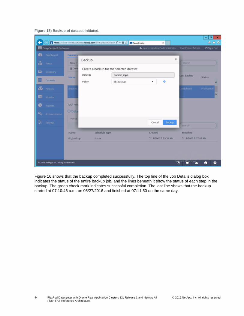
44 FlexPod Datacenter with Oracle Real Application Clusters 12c Release 1 and NetApp All Flash FAS Reference Architecture
© 2016 NetApp, Inc. All rights reserved.
Figure 15) Backup of dataset initiated.
Figure 16 shows that the backup completed successfully. The top line of the Job Details dialog box
indicates the status of the entire backup job, and the lines beneath it show the status of each step in the
backup. The green check mark indicates successful completion. The last line shows that the backup
started at 07:10:46 a.m. on 05/27/2016 and finished at 07:11:50 on the same day.
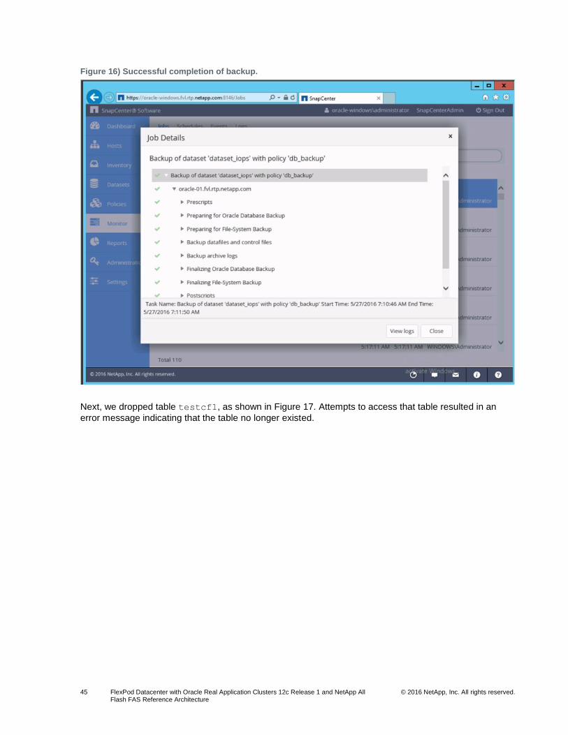
45 FlexPod Datacenter with Oracle Real Application Clusters 12c Release 1 and NetApp All Flash FAS Reference Architecture
© 2016 NetApp, Inc. All rights reserved.
Figure 16) Successful completion of backup.
Next, we dropped table testcf1, as shown in Figure 17. Attempts to access that table resulted in an
error message indicating that the table no longer existed.

46 FlexPod Datacenter with Oracle Real Application Clusters 12c Release 1 and NetApp All Flash FAS Reference Architecture
© 2016 NetApp, Inc. All rights reserved.
Figure 17) Table dropped.
In this example, we assumed that the table drop was a mistake and the data it contained was needed.
SnapCenter provides different options for restoring a table. We could have restored the table from a
backup, but for this example, the entire database was restored to a point in time right before the table was
dropped. Figure 18 shows a list of available backups for the recovery. The first entry in the list
corresponds in time to the backup that was performed before the table was mistakenly dropped.
Note: The Oracle system change number (SCN) has a value of 366331951.

47 FlexPod Datacenter with Oracle Real Application Clusters 12c Release 1 and NetApp All Flash FAS Reference Architecture
© 2016 NetApp, Inc. All rights reserved.
Figure 18) Choose a backup to restore.
From the Choose Recovery Scope dialog box, we chose the scope of the restore operation to include all
data files and control files. Figure 19 shows that the Until SCN option was selected. This option
determines which archive logs to apply. Selecting the All Logs option would result in all logs being
applied, which would recover the database up to the present time. Our dropped table does not exist at the
present time, so selecting that option would not restore the lost table. We specified the SCN for the last
backup performed before the table was lost and clicked Next to proceed with the restore operation.

48 FlexPod Datacenter with Oracle Real Application Clusters 12c Release 1 and NetApp All Flash FAS Reference Architecture
© 2016 NetApp, Inc. All rights reserved.
Figure 19) Database recovery scope.
Figure 20 shows that the restore option completed successfully.

49 FlexPod Datacenter with Oracle Real Application Clusters 12c Release 1 and NetApp All Flash FAS Reference Architecture
© 2016 NetApp, Inc. All rights reserved.
Figure 20) Successful completion of restore operation.
Figure 21 shows another Oracle SQLPlus session. Table testcf1 has been restored, and we can now
execute queries on it. Also, the row count for the table is the same as before it was dropped.

50 FlexPod Datacenter with Oracle Real Application Clusters 12c Release 1 and NetApp All Flash FAS Reference Architecture
© 2016 NetApp, Inc. All rights reserved.
Figure 21) Table testcf1 restored.
SnapCenter was also used to create a clone of the database. The clone was mounted as a separate
database instance, and I/O was performed on it to demonstrate the usefulness of a database clone for
other activities such as data analytics or test/development activities. Figure 22 shows a list of existing
databases, including the original RAC database IOPS, and two clones (iopscl and latest), which were
created from backups of the IOPS database.

51 FlexPod Datacenter with Oracle Real Application Clusters 12c Release 1 and NetApp All Flash FAS Reference Architecture
© 2016 NetApp, Inc. All rights reserved.
Figure 22) List of databases (including two clones).
Clones of RAC databases are created as single-instance databases. In Figure 22, iopscl is highlighted.
Database clones are fully functional database instances and are independent of the original database.
Figure 23 shows that we are able to log in to the iopscl database clone, execute a query, and then create
a new table. We completed the following tasks:
1. Set the Oracle System ID (ORACLE_SID) environmental variable to the SID of the clone (iopscl)
2. Opened a SQLPlus session and queried the v$instance view to verify that we are connected to the database clone
3. Queried an existing table, testcf1, to make sure it existed and contained data
4. Created a copy of that table, demonstrating that our database clone was writable
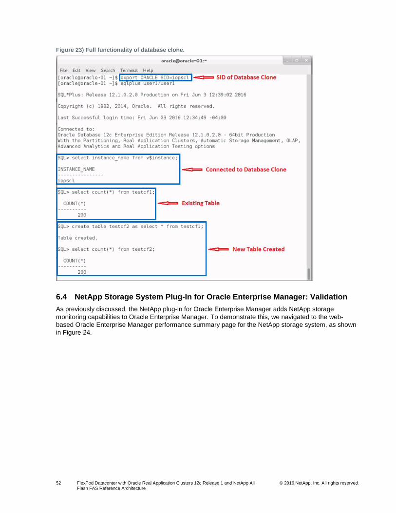
52 FlexPod Datacenter with Oracle Real Application Clusters 12c Release 1 and NetApp All Flash FAS Reference Architecture
© 2016 NetApp, Inc. All rights reserved.
Figure 23) Full functionality of database clone.
6.4 NetApp Storage System Plug-In for Oracle Enterprise Manager: Validation
As previously discussed, the NetApp plug-in for Oracle Enterprise Manager adds NetApp storage
monitoring capabilities to Oracle Enterprise Manager. To demonstrate this, we navigated to the web-
based Oracle Enterprise Manager performance summary page for the NetApp storage system, as shown
in Figure 24.

53 FlexPod Datacenter with Oracle Real Application Clusters 12c Release 1 and NetApp All Flash FAS Reference Architecture
© 2016 NetApp, Inc. All rights reserved.
Figure 24) Oracle Enterprise Manager NetApp performance summary page.
From the screen capture in Figure 14, we viewed the status of the storage system, including the following
information with corresponding numerical identification:
1. Storage system status (indicating that the storage system is up)
2. Name of the storage cluster (fvl1-8080)
3. Serial number of the storage cluster
4. Number of storage nodes (2)
5. Storage capacity and aggregate space utilization; in this example, the aggregate capacity was 54.92TB. The total aggregate capacity used was 6.35TB (11.56%), with 48.56TB (88.43%) remaining.
6. CPU utilization by node, which has ramped up to about 73%, reflecting the application of a heavy OLTP workload
7. Network load, showing some I/O; however, the network I/O was pretty low, peaking at 90KBps.
Note: Low network throughput was expected because we used FC for database I/O.
8. Throughput by aggregate, showing a throughput of about 80,000 x 4KB blocks per second, per controller, once again indicating a that heavy workload has been applied
9. Throughput by physical port, indicating the presence of workload
Note: These are Ethernet ports, so as with network load, the I/O was low.
10. Incidents and problems, indicating that none were reported
11. Additional reports
Drilling down, we were also able to view additional reports.

54 FlexPod Datacenter with Oracle Real Application Clusters 12c Release 1 and NetApp All Flash FAS Reference Architecture
© 2016 NetApp, Inc. All rights reserved.
Figure 25 shows storage aggregate utilization and the number of volumes for the storage system.
Figure 25) Oracle Enterprise Manager storage aggregate utilization report.
For clarity, the Aggregate Space Utilization section of Figure 25 was broken out and presented in Figure
26, which provides a graphical report on aggregate space utilization. Per the graphic and the tabular data
in Figure 25, there are two data aggregates, aggr1_node01 and aggr1_node02. Each aggregate has a
total capacity of 27756GB. Aggr1_node01 has 24806GB of available space, with 2950GB being used;
and aggr1_node02 has 24896GB of available space, with 2860GB being used. Each aggregate is within
the 10% to 11% utilization range.
Figure 26) Oracle Enterprise Manager storage aggregate space utilization report.

55 FlexPod Datacenter with Oracle Real Application Clusters 12c Release 1 and NetApp All Flash FAS Reference Architecture
© 2016 NetApp, Inc. All rights reserved.
For clarity, the Volumes in Aggregate and Aggregate Space Utilization in Percentage sections of Figure
25 were been broken out, as shown in Figure 27 and Figure 28, respectively.
Figure 27) Oracle Enterprise Manager volumes in aggregate report.
In Figure 27, the Oracle Enterprise Manager screen shows the number of volumes per storage
aggregate. Aggr_node01 has 12 volumes, and aggr_node02 has 10 volumes. Figure 28 shows
percent space utilization for each aggregate in pie chart format.
Figure 28) Oracle Enterprise Manager aggregate space utilization in percentage report.

56 FlexPod Datacenter with Oracle Real Application Clusters 12c Release 1 and NetApp All Flash FAS Reference Architecture
© 2016 NetApp, Inc. All rights reserved.
Oracle Enterprise Manager also provides a storage cluster node overview, as shown in Figure 29. It
shows the following information about the storage cluster nodes:
Node name
IP address
Uptime
ONTAP version
Model
Node ID
Serial number
Number of CPUs per node
Figure 29) Oracle Enterprise Manager cluster node overview report.
In Figure 29, the colors blue and orange are used to distinguish between the two storage nodes. On the
Cluster Node Overview screen, the first node has an uptime of 42 days, and the second node has an
uptime of 49 days. Also, each node has 20 processors, and each node is running clustered Data ONTAP
Release 8.3.1.
Finally, the Oracle Enterprise Manager screen shown in Figure 30 provides details of space utilization at
the SVM level.

57 FlexPod Datacenter with Oracle Real Application Clusters 12c Release 1 and NetApp All Flash FAS Reference Architecture
© 2016 NetApp, Inc. All rights reserved.
Figure 30) Oracle Enterprise Manager SVM volumes and space utilization report.
More specifically, the Oracle Enterprise Manager screen in Figure 30 shows that there is only one SVM
named Infra-SVM. It has 22 volumes and 20225GB of storage, with 5553GB used and 14671GB
remaining.
The reports in this section are just a few of the reports available with Oracle Enterprise Manager and the
NetApp Oracle Enterprise Manager plug-in. Many of these reports are real time, and all of them are rich in
detail and graphical content.
6.5 Resiliency Validation
To demonstrate the enterprise-class resiliency of this FlexPod solution, a variety of failure scenarios were
induced into the system while the database servers and storage were subjected to the identical workload
used for performance validation. The goal of this validation was to subject the FlexPod infrastructure to a
heavy workload and measure the effect of the specific failure scenario on the overall performance and
stability of the system. To pass each of these tests, the database and storage had to continue to serve
I/O for the duration of the event. Some of these tests were extremely disruptive. Therefore, minimal drops
in overall performance were considered acceptable as long as the overall system continued to function
nominally and performance returned to prefailure levels after the failure was corrected.
Link Failure Tests
These validation tests were intentionally disconnected and then reconnected to a single FCoE link in the
environment while under a heavy OLTP workload of approximately 240,000 IOPS. The workload was
allowed to run for eight minutes to make sure of a steady state before introducing the first failure. The
workload was then allowed to run for five minutes before the failure was corrected.
Figure 31 shows the IOPS during these tests, with a red arrow to indicate when the failure occurred and a
green arrow to indicate when the link was restored. As shown in Figure 31, the observed impact on I/O
was minimal.

58 FlexPod Datacenter with Oracle Real Application Clusters 12c Release 1 and NetApp All Flash FAS Reference Architecture
© 2016 NetApp, Inc. All rights reserved.
Figure 31) IOPS during FCoE link failure test.
Storage Controller Failover Tests
In these failover tests, a catastrophic failure was intentionally induced into one controller of the AFF8080
EX storage system while a 240,000 IOPS OLTP workload was in process. The surviving storage
controller was then required to service the entire prefailure workload.
The failover tests used the following methodology:
1. The OLTP workload was applied with both controllers active for about eight minutes to establish steady state performance.
2. After about eight minutes, a failure was induced on controller 2, forcing controller 1 to service the entire workload. During this time, controller 2 rebooted to a preoperational state and then entered a wait period. After the wait period, the system started an automatic giveback, and controller 2 resumed normal operations several minutes later.
Figure 32 shows the IOPS observed during this failover test. A red arrow indicates when the controller
went offline. Green arrows indicate when the controller came back online and when giveback was
complete. The following observations were made during the failover tests:
As expected, there was a noticeable, sudden drop in IOPS at the moment controller 2 went offline.
I/O resumed after takeover was complete, but was on average approximately 25% lower than when both controllers were online. Storage controller CPU utilization was approximately 93% while in takeover mode, compared to 80% while in active-active mode.
After the failed controller was restored, performance quickly returned to prefailure levels.
At no time were any issues observed with the database or database application. The database remained open and available, and the database job completed successfully without any errors.

59 FlexPod Datacenter with Oracle Real Application Clusters 12c Release 1 and NetApp All Flash FAS Reference Architecture
© 2016 NetApp, Inc. All rights reserved.
Figure 32) Observed IOPS during controller failover test.
Cisco UCS Fabric Interconnect Failover Test
The Cisco UCS fabric interconnect failover test intentionally rebooted the primary Cisco UCS fabric
interconnect while it ran the 240,000 IOPS OLTP workload. During the failure, all I/O was forced to
traverse the secondary fabric interconnect. For this failover test, the workload was allowed to run for
about five minutes at steady state before the fabric interconnect was rebooted. During this test, a brief
drop in IOPS occurred before a quick recovery to near prefailure levels was observed, with another brief
drop in IOPS when the fabric interconnect resumed operation. Figure 33 shows the IOPS observed
during this test, with a red arrow indicating when the fabric interconnect went offline. A green arrow
indicates a return to steady state after the failed fabric interconnect came back online.
Figure 33) Observed IOPS during fabric interconnect failover test.
Conclusion
FlexPod Datacenter is the optimal infrastructure foundation on which to deploy Oracle databases. Cisco
and NetApp have created a platform that is both flexible and scalable for multiple use cases and designs.

60 FlexPod Datacenter with Oracle Real Application Clusters 12c Release 1 and NetApp All Flash FAS Reference Architecture
© 2016 NetApp, Inc. All rights reserved.
The flexibility and scalability of FlexPod allow you to start out with a right-sized infrastructure that can
grow with and adapt to your evolving business requirements, from single-instance Oracle databases to
large-scale Oracle RAC data warehouses.
In the verification tests of this reference architecture, the total IOPS and latency as measured at the
database exceeded performance expectations. The NetApp FlexPod Datacenter configuration with AFF
reached over 200,000 combined IOPS and read latencies of less than 1ms. In addition, this verification
demonstrated that the solution as documented could maintain these performance levels even in the event
of a storage, host, or network failure.
Appendix
Linux Kernel Parameter Settings
Table 10) Linux Kernel parameter settings.
Linux Sysctl.conf Settings
Parameter Name Value
kernel.msgmnb 65536
kernel.msgmax 65536
kernel.shmmax 202659594240
kernel.shmall 4294967296
kernel.shmmni 4096
kernel.sem 8192 48000 8192 8192
fs.file-max 6815744
net.ipv4.ip_local_port_range 9000 65500
net.core.rmem_default 4194304
net.core.rmem_max 16777216
net.core.wmem_default 262144
net.core.wmem_max 16777216
net.ipv4.ipfrag_high_thresh 524288
net.ipv4.ipfrag_low_thresh 393216
net.ipv4.tcp_rmem 4096 524288 16777216
net.ipv4.tcp_wmem 4096 524288 16777216
net.ipv4.tcp_timestamps 0
net.ipv4.tcp_sack 0
net.ipv4.tcp_window_scaling 1
net.core.optmem_max 524287
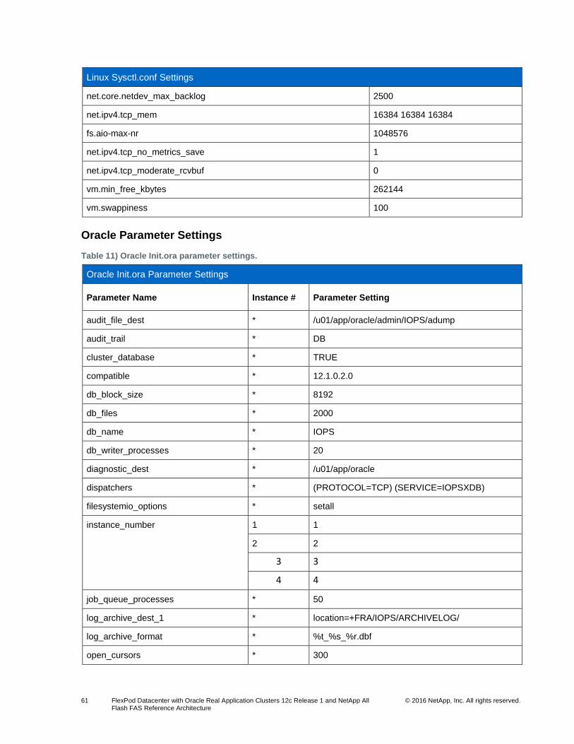
61 FlexPod Datacenter with Oracle Real Application Clusters 12c Release 1 and NetApp All Flash FAS Reference Architecture
© 2016 NetApp, Inc. All rights reserved.
Linux Sysctl.conf Settings
net.core.netdev_max_backlog 2500
net.ipv4.tcp_mem 16384 16384 16384
fs.aio-max-nr 1048576
net.ipv4.tcp_no_metrics_save 1
net.ipv4.tcp_moderate_rcvbuf 0
vm.min_free_kbytes 262144
vm.swappiness 100
Oracle Parameter Settings
Table 11) Oracle Init.ora parameter settings.
Oracle Init.ora Parameter Settings
Parameter Name Instance # Parameter Setting
audit_file_dest * /u01/app/oracle/admin/IOPS/adump
audit_trail * DB
cluster_database * TRUE
compatible * 12.1.0.2.0
db_block_size * 8192
db_files * 2000
db_name * IOPS
db_writer_processes * 20
diagnostic_dest * /u01/app/oracle
dispatchers * (PROTOCOL=TCP) (SERVICE=IOPSXDB)
filesystemio_options * setall
instance_number 1 1
2 2
3 3
4 4
job_queue_processes * 50
log_archive_dest_1 * location=+FRA/IOPS/ARCHIVELOG/
log_archive_format * %t_%s_%r.dbf
open_cursors * 300

62 FlexPod Datacenter with Oracle Real Application Clusters 12c Release 1 and NetApp All Flash FAS Reference Architecture
© 2016 NetApp, Inc. All rights reserved.
Oracle Init.ora Parameter Settings
optimizer_adaptive_features * FALSE
parallel_max_servers * 8
parallel_min_servers * 0
pga_aggregate_target * 2147483648
processes * 900
remote_listener * flexrac.fvl.rtp.netapp.com:1521, flexrac.fvl.rtp.net
remote_login_passwordfile * EXCLUSIVE
session_cached_cursors * 200
sga_max_size * 4294967296
sga_target * 4294967296
shared_pool_size * 486539264
thread 1 1
2 2
3 3
4 4
undo_tablespace 1 UNDOTS01
2 UNDOTS02
3 UNDOTS03
4 UNDOTS04
control_files * +DATA/IOPS/control01.ctl
* +DATA/IOPS/control02.ctl
Best Practices
Table 12 lists the recommended NetApp best practices for designing or implementing Oracle 12c RAC
databases running on FlexPod Datacenter with RHEL 7.1.
Table 12) Oracle 12c RAC on FlexPod best practices.
Best Practice Area Best Practice Details
Cisco UCS design Verify that there is sufficient bandwidth to each Cisco UCS blade by selecting appropriate IOM and adapter cards.
Configure the fabric interconnects for FC switch mode before completing configuration. FC switch mode requires a reboot of the fabric interconnect.
NetApp storage with Oracle Databases
Review best practice details for NetApp storage with Oracle databases in TR-3633: Oracle Databases on Data ONTAP.

63 FlexPod Datacenter with Oracle Real Application Clusters 12c Release 1 and NetApp All Flash FAS Reference Architecture
© 2016 NetApp, Inc. All rights reserved.
Acknowledgements
This document is a result of the work, prior documentation, and assistance from David Arnette, Dave
Derry, Ebin Kadavy, Chris Lemmons, Troy Mangum, and the entire Integrated Infrastructures team at
NetApp.
References
This section provides links to additional information and reference material for the subjects contained in
this document.
Cisco Unified Computing System
Cisco Design Zone for FlexPod http://www.cisco.com/c/en/us/solutions/enterprise/data-center-designs-cloud-computing/landing_flexpod.html
Cisco Unified Computing System http://www.cisco.com/c/en/us/products/servers-unified-computing/index.html
Cisco UCS 6200 Series Fabric Interconnects http://www.cisco.com/en/US/products/ps11544/index.html
Cisco UCS 5100 Series Blade Server Chassis http://www.cisco.com/en/US/products/ps10279/index.html
Cisco UCS B-Series Blade Servers http://www.cisco.com/c/en/us/products/servers-unified-computing/ucs-b-series-blade-servers/index.html
Cisco UCS Adapters http://www.cisco.com/en/US/products/ps10277/prod_module_series_home.html
Cisco UCS Manager http://www.cisco.com/en/US/products/ps10281/index.html
Cisco Nexus Networking
Cisco Nexus 9000 Series Switches http://www.cisco.com/c/en/us/products/switches/nexus-9000-series-switches/index.html
Cisco Nexus 9396PX Switch information http://www.cisco.com/c/en/us/support/switches/nexus-9396px-switch/model.html
NetApp FAS Storage
Clustered Data ONTAP 8.3.1 Documentation http://mysupport.netapp.com/documentation/docweb/index.html?productID=62175&language=en-US
TR-3982: NetApp Clustered Data ONTAP 8.3 http://www.netapp.com/us/media/tr-3982.pdf
TR-4514: NetApp AFF8080A EX Storage Efficiency and Performance with Oracle Database http://www.netapp.com/us/media/tr-4514.pdf
TR-4490: Oracle Database 12c Performance: Protocol Comparison Using Clustered Data ONTAP
http://www.netapp.com/us/media/tr-4490.pdf
TR-3633: Oracle Databases on Data ONTAP
http://www.netapp.com/us/media/tr-3633.pdf

64 FlexPod Datacenter with Oracle Real Application Clusters 12c Release 1 and NetApp All Flash FAS Reference Architecture
© 2016 NetApp, Inc. All rights reserved.
NetApp SnapCenter
NetApp SnapCenter Software Resources: http://mysupport.netapp.com/snapcenter/resources
NetApp Storage System Plug-In for Oracle Enterprise Manager
Description: NetApp Storage System Plug-In for Oracle Enterprise Manager
http://mysupport.netapp.com/tools/info/ECMLP2437366I.html?productID=61952/
NetApp Storage System Plug-In for Oracle Enterprise Manager
http://community.netapp.com/t5/FAS-and-Data-ONTAP-Articles-and-Resources/NetApp-Storage-
System-Plug-in-for-Oracle-Enterprise-Manager/ta-p/86546
NetApp Storage System Plug-In 12.1.0.3.0 for Oracle Enterprise Manager 12c Installation and
Administration Guide
http://community.netapp.com/t5/FAS-and-Data-ONTAP-Articles-and-Resources/NetApp-Storage-
System-Plug-in-for-Oracle-Enterprise-Manager/ta-p/86546
Interoperability Matrixes
Cisco UCS Hardware and Software Interoperability Tool http://www.cisco.com/web/techdoc/ucs/interoperability/matrix/matrix.html
NetApp Interoperability Matrix Tool http://support.netapp.com/matrix
Version History
Version Date Document Version History
Version 1.0 September 2016 Initial release

65 FlexPod Datacenter with Oracle Real Application Clusters 12c Release 1 and NetApp All Flash FAS Reference Architecture
© 2016 NetApp, Inc. All rights reserved.
Refer to the Interoperability Matrix Tool (IMT) on the NetApp Support site to validate that the exact product and feature versions described in this document are supported for your specific environment. The NetApp IMT defines the product components and versions that can be used to construct configurations that are supported by NetApp. Specific results depend on each customer’s installation in accordance with published specifications.
Copyright Information
Copyright © 1994–2016 NetApp, Inc. All rights reserved. Printed in the U.S. No part of this document covered by copyright may be reproduced in any form or by any means—graphic, electronic, or mechanical, including photocopying, recording, taping, or storage in an electronic retrieval system—without prior written permission of the copyright owner.
Software derived from copyrighted NetApp material is subject to the following license and disclaimer:
THIS SOFTWARE IS PROVIDED BY NETAPP “AS IS” AND WITHOUT ANY EXPRESS OR IMPLIED WARRANTIES, INCLUDING, BUT NOT LIMITED TO, THE IMPLIED WARRANTIES OF MERCHANTABILITY AND FITNESS FOR A PARTICULAR PURPOSE, WHICH ARE HEREBY DISCLAIMED. IN NO EVENT SHALL NETAPP BE LIABLE FOR ANY DIRECT, INDIRECT, INCIDENTAL, SPECIAL, EXEMPLARY, OR CONSEQUENTIAL DAMAGES (INCLUDING, BUT NOT LIMITED TO, PROCUREMENT OF SUBSTITUTE GOODS OR SERVICES; LOSS OF USE, DATA, OR PROFITS; OR BUSINESS INTERRUPTION) HOWEVER CAUSED AND ON ANY THEORY OF LIABILITY, WHETHER IN CONTRACT, STRICT LIABILITY, OR TORT (INCLUDING NEGLIGENCE OR OTHERWISE) ARISING IN ANY WAY OUT OF THE USE OF THIS SOFTWARE, EVEN IF ADVISED OF THE POSSIBILITY OF SUCH DAMAGE.
NetApp reserves the right to change any products described herein at any time, and without notice. NetApp assumes no responsibility or liability arising from the use of products described herein, except as expressly agreed to in writing by NetApp. The use or purchase of this product does not convey a license under any patent rights, trademark rights, or any other intellectual property rights of NetApp.
The product described in this manual may be protected by one or more U.S. patents, foreign patents, or pending applications.
RESTRICTED RIGHTS LEGEND: Use, duplication, or disclosure by the government is subject to restrictions as set forth in subparagraph (c)(1)(ii) of the Rights in Technical Data and Computer Software clause at DFARS 252.277-7103 (October 1988) and FAR 52-227-19 (June 1987).
Trademark Information
NetApp, the NetApp logo, Go Further, Faster, AltaVault, ASUP, AutoSupport, Campaign Express, Cloud
ONTAP, Clustered Data ONTAP, Customer Fitness, Data ONTAP, DataMotion, Flash Accel, Flash
Cache, Flash Pool, FlashRay, FlexArray, FlexCache, FlexClone, FlexPod, FlexScale, FlexShare, FlexVol,
FPolicy, GetSuccessful, LockVault, Manage ONTAP, Mars, MetroCluster, MultiStore, NetApp Fitness,
NetApp Insight, OnCommand, ONTAP, ONTAPI, RAID DP, RAID-TEC, SANshare, SANtricity,
SecureShare, Simplicity, Simulate ONTAP, SnapCenter, SnapCopy, Snap Creator, SnapDrive,
SnapIntegrator, SnapLock, SnapManager, SnapMirror, SnapMover, SnapProtect, SnapRestore,
Snapshot, SnapValidator, SnapVault, SolidFire, StorageGRID, Tech OnTap, Unbound Cloud, WAFL, and
other names are trademarks or registered trademarks of NetApp, Inc. in the United States and/or other
countries. All other brands or products are trademarks or registered trademarks of their respective holders
and should be treated as such. A current list of NetApp trademarks is available on the web at
http://www.netapp.com/us/legal/netapptmlist.aspx. TR-4552-0919
Recommended