2 Siemens HA 35.41 · 2006
Fixed-Mounted Circuit-Breaker Switchgear Type NXPLUS C, up to 24 kV, Gas-Insulated
Contents Application
Types
© Siemens AG 2006
Page
Application
Types, typical uses,ratings 2 to 4
Requirements
Features, safety, technology 4 and 5
Technical Data
Electrical data 6 and 7Room planning 8Shipping data, classification 9
Dimensions
Front views, sections,floor openings, fixing points 10 to 16
Product Range
Single-busbar panels 17 to 19Double-busbar panels 20
Design
Basic panel design 21
Components
Vacuum circuit-breaker 22 and 23Three-position switch 24 and 25HV HRC fuse assembly 26 and 27Vacuum contactor, motor protection 28Busbars 29Current and voltage transformers 30 and 31Panel connection 32 to 35Indicating and measuring equipment 36 to 39
Standards
Standards, specifications, guidelines 40 and 41
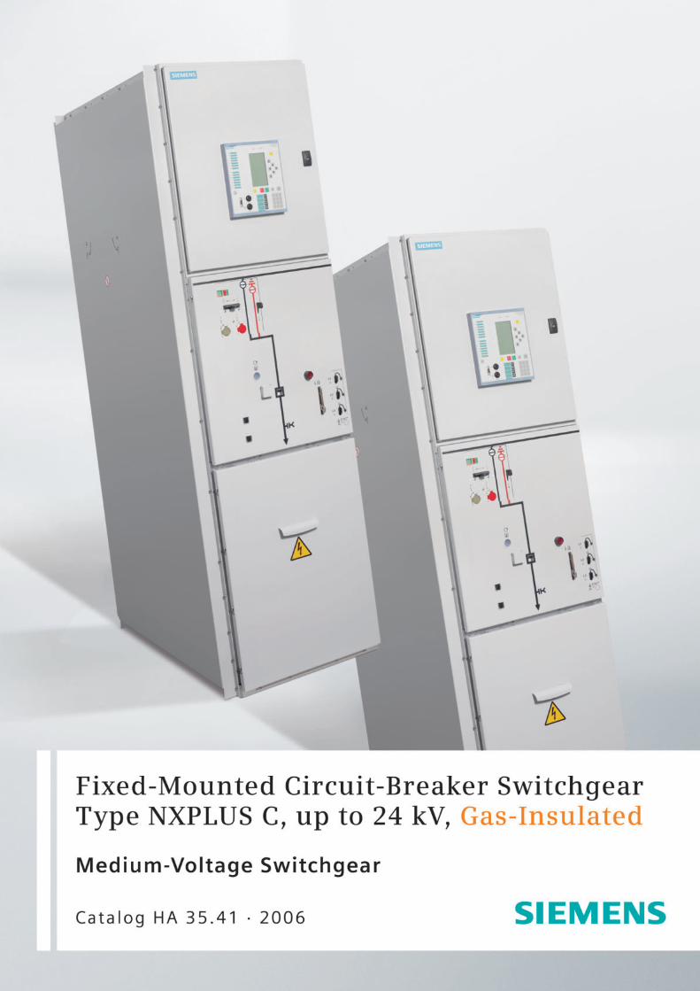
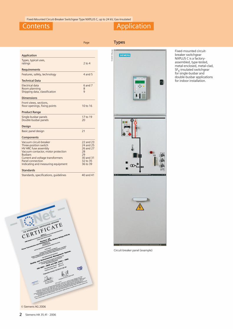
Fixed-mounted circuit-breaker switchgearNXPLUS C is a factory-assembled, type-tested,metal-enclosed, metal-clad,SF6-insulated switchgearfor single-busbar anddouble-busbar applicationsfor indoor installation.
Circuit-breaker panel (example)
R-HA
35-1
05a
eps
3Siemens HA 35.41 · 2006
Fixed-Mounted Circuit-Breaker Switchgear Type NXPLUS C, up to 24 kV, Gas-Insulated
R-HA
35-1
07.e
ps
R-HA
35-1
06.e
ps
R-HA35-109.eps
R-HA
35-1
23.e
ps
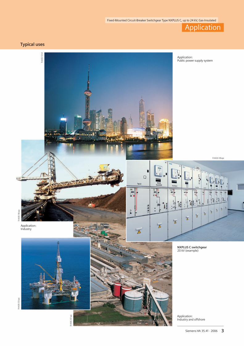
Typical uses
Application
Application:Public power supply system
NXPLUS C switchgear20 kV (example)
Application:Industry
Application:Industry and offshore
R-HA
35-1
22.ti
f

4 Siemens HA 35.41 · 2006
Fixed-Mounted Circuit-Breaker Switchgear Type NXPLUS C, up to 24 kV, Gas-Insulated
Typical uses, ratings Features
Environmental independence
Welded switchgear vesselsmade of stainless steel withoutseals make NXPLUS C switch-gear
• Insensitive to aggressiveambient conditions, such as
– Salt water– Air humidity– Dust– Temperature
• Hermetically tight to ingressof foreign bodies, such as
– Dust– Dirt– Small animals
• Independent of site altitude
Compact design
Thanks to the SF6-insulation,compact dimensions arepossible
Thus,
• Existing switchgear roomscan be used effectively
• New constructions cost little
• Costly city-area space is saved
Maintenance-free design
Switchgear vessels designedas sealed pressure systems,maintenance-free switchingdevices and enclosed cableplugs ensure
• Maximized power supplyreliability
• Personnel safety
• Sealed-for-life design accord-ing to IEC 62 271-200 (sealedpressure system)
• Installation, operation, exten-sion and replacement with-out SF6-gas work
• Reduced operating costs
• Cost-efficient investment
• No maintenance cycles
Innovations
The use of digital second-ary systems and com-bined protection andcontrol devices ensures
• Clear integration in proc-ess control systems
• Flexible and highly sim-plified adaptation to newsystem conditions andthus to cost-efficientoperation
Fixed-mounted circuit-breaker switchgearNXPLUS C is used in transformerand switching substations, e.g., in:
■ Power supply companies■ Power stations■ Cement industry■ Automobile industry■ Iron and steel works■ Rolling mills■ Mining industry■ Textile, paper and food industries■ Chemical industry■ Petroleum industry■ Pipeline installations■ Offshore installations■ Electrochemical plants■ Petrochemical plants■ Shipbuilding industry■ Diesel power plants■ Emergency power supply installations■ Lignite open-cast mines■ Traction power supply systems
1) 42 kV/95 kV according to somenational requirements
2) 1200 mm for rated normalfeeder currents of 2000 A,2300 A and 2500 A
Application Requirements
Electrical data (maximum values) and dimensions
Rated voltage kV 7.2 12 15 17.5 24
Rated frequency Hz 50/60 50/60 50/60 50/60 50/60
Rated short-duration power-frequency withstand voltage
kV 20 28 1) 36 38 50
Rated lightning impulsewithstand voltage
kV 60 75 1) 95 95 125
Rated peak withstand current kA 80 80 80 63 63
Rated short-circuit makingcurrent
kA 80 80 80 63 63
Rated short-timewithstand current 3 s
kA 31.5 31.5 31.5 25 25
Rated short-circuit breakingcurrent
kA 31.5 31.5 31.5 25 25
Rated normal current of busbar A 2500 2500 2500 2500 2500
Rated normal current offeeders
A 2500 2500 2500 2000 2000
Width mm 600 2) 600 2) 600 2) 600 2) 600 2)
Depth – without pressurerelief duct at the rear
– with pressurerelief duct at the rear
mm
mm
1100
1225
1100
1225
1100
1225
1100
1225
1100
1225
Height mm 2250 2250 2250 2250 2250
5Siemens HA 35.41 · 2006
Fixed-Mounted Circuit-Breaker Switchgear Type NXPLUS C, up to 24 kV, Gas-Insulated
Safety Technology
Requirements
Personal safety
• Safe-to-touch and hermetical-ly sealed primary enclosure
• Cable terminations, busbarsand voltage transformers aresurrounded by earthed layers
• All high-voltage parts includ-ing the cable terminations,busbars and voltage trans-formers are metal enclosed
• Capacitive voltage detectionsystem for verification of safeisolation from supply
• Operating mechanisms andauxiliary switches safely ac-cessible outside the primaryenclosure (switchgear vessel)
• Due to design an operationis only possible with closedenclosure
• Standard degree of protec-tion IP 65 for all high-voltageparts of the primary circuit,IP 3XD for the switchgearenclosure according toIEC 60 529 and VDE 0470-1
• High resistance to internalarcs by logical mechanicalinterlocks and testedswitchgear enclosure
• Arc-fault tested panelsup to 31.5 kA
• Logical mechanical interlocksprevent maloperation
• Make-proof earthing bymeans of the vacuum circuit-breaker
Security of operation
• Hermetically sealed primaryenclosure independent ofenvironmental effects (dirt,moisture and small animals)
• Maintenance-free inan indoor environment(IEC 60 694 andVDE 0670-1000)
• Operating mechanisms ofswitching devices accessibleoutside the primary enclo-sure (switchgear vessel)
• Metal-coated, plug-in induc-tive voltage transformersmounted outside the gascompartments
• Ring-core current transform-ers mounted outside the gascompartments
• Complete logical mechanicalinterlocking system
• Welded switchgear vessels,sealed for life
• Minimum fire load
• Type and routine-tested
• Standardized, NC productionprocesses
• Quality assurance in accord-ance with DIN EN ISO 9001
• More than 300,000switchgear panels of Siemensin operation worldwide formany years
• Option: Aseismic design
Reliability
• Type and routine-tested
• Standardized, NC productionprocesses
• Quality assurance in accord-ance with DIN EN ISO 9001
• More than 300,000switchgear panels of Siemensin operation worldwide formany years
General
• Three-pole enclosure of theprimary part consisting of aswitchgear vessel made ofstainless steel
• Insulating gas SF6
• Three-position switch asbusbar disconnector andfeeder earthing switch
• Make-proof earthing bymeans of the vacuum circuit-breaker
• Compact dimensions due toSF6-insulation
• Hermetically welded switch-gear vessel made of stainlesssteel without seals
• Single-pole, solid-insulated,screened busbars, plug-intype
• Cable connection with out-side-cone plug-in system, orfor connection of solid-insu-lated bars
• Wall-standing or free-stand-ing arrangement
• Cable connection access fromfront
• Option: Cable connectionaccess from rear (only circuit-breaker panel 1250 A)
• Installation and extension ofexisting switchgear on bothsides without gas work andwithout modification of exist-ing panels
Interlocks
• According to IEC 62 271-200and VDE 0671-200
• Logical mechanical interlocksprevent maloperation
• Three-position disconnectorcan only be operated with cir-cuit-breaker in OPEN position
• Circuit-breaker or contactorcan only be operated withthree-position switch in endposition and operating leverremoved
• Switch-disconnector, contac-tor, ring-main and meteringpanels are not interlockeddue to their own switchingcapacity
• Three-position disconnectorinterlocked against the cir-cuit-breaker in circuit-breakerpanels and in bus sectionali-zers with one panel width
• Locking device for feeder
• Locking device for three-position switch
• Cable compartment cover(access to HV HRC fuses)always interlocked againstthe three-position switch-disconnector in panels withHV HRC fuses (switch-discon-nector panel, metering paneland contactor panel withfuses)
• Option: Cable compartmentcover interlocked against thethree-position switch (circuit-breaker panel, disconnectorpanel, contactor panel with-out fuses, ring-main panel)
• Option: Electromagneticinterlocks
• Option: Actuating openingscan be locked with padlocks
• Option: Locking device for“feeder earthed”
Modular design
• Panel replacement possiblewithout SF6-gas work
• Low-voltage compartmentcan be removed, plug-in buswires
Transformers
• Current transformers notsubjected to dielectric stress
• Easy replacement of ring-corecurrent transformers
• Metal-coated, plug-in anddisconnectable voltage trans-formers
Vacuum circuit-breaker
• Maintenance-free undernormal ambient conditionsaccording to IEC 60 694 andVDE 0670-1000
• No relubrication or readjust-ment
• Up to 10,000 operatingcycles
• Vacuum-tight for life
Secondary systems
• Standard protection,measuring and controlequipment
• Option: Digital multifunctionprotection relay with inte-grated protection, control,communication, operatingand monitoring functions
• Can be integrated in processcontrol systems
6 Siemens HA 35.41 · 2006
Fixed-Mounted Circuit-Breaker Switchgear Type NXPLUS C, up to 24 kV, Gas-Insulated
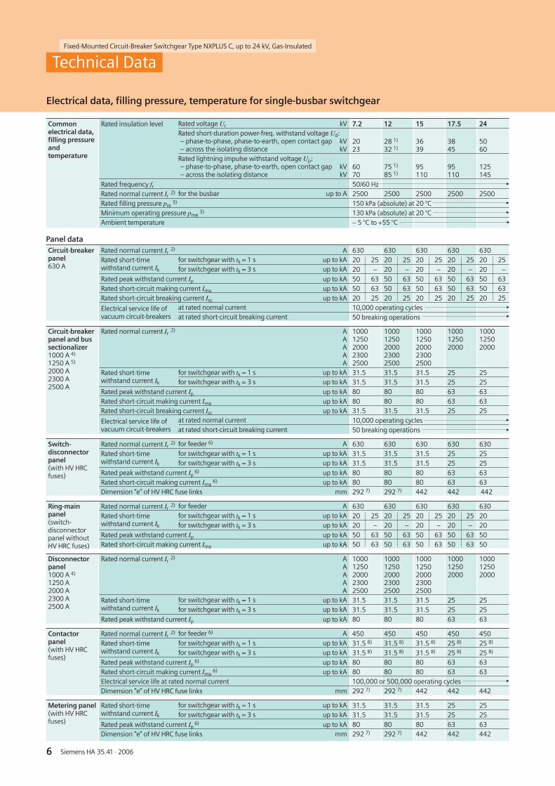
Electrical data, filling pressure, temperature for single-busbar switchgear
Technical Data
Commonelectrical data,filling pressureandtemperature
Rated insulation level Rated voltage Ur kV 7.2 12 15 17.5 24Rated short-duration power-freq. withstand voltage Ud:– phase-to-phase, phase-to-earth, open contact gap kV– across the isolating distance kV
2023
28 1)
32 1)3639
3845
5060
Rated lightning impulse withstand voltage Up:– phase-to-phase, phase-to-earth, open contact gap kV– across the isolating distance kV
6070
75 1)
85 1)95110
95110
125145
Rated frequency fr 50/60 HzRated normal current Ir
2) for the busbar up to A 2500 2500 2500 2500 2500Rated filling pressure pre
3) 150 kPa (absolute) at 20 °CMinimum operating pressure pme
3) 130 kPa (absolute) at 20 °CAmbient temperature – 5 °C to +55 °C
Panel dataCircuit-breakerpanel630 A
Rated normal current Ir2) A 630 630 630 630 630
Rated short-timewithstand current Ik
for switchgear with tk = 1 s up to kA 20 25 20 25 20 25 20 25 20 25for switchgear with tk = 3 s up to kA 20 – 20 – 20 – 20 – 20 –
Rated peak withstand current Ip up to kA 50 63 50 63 50 63 50 63 50 63Rated short-circuit making current Ima up to kA 50 63 50 63 50 63 50 63 50 63Rated short-circuit breaking current Isc up to kA 20 25 20 25 20 25 20 25 20 25
Electrical service life ofvacuum circuit-breakers
at rated normal current 10,000 operating cyclesat rated short-circuit breaking current 50 breaking operations
Circuit-breakerpanel and bussectionalizer1000 A 4)
1250 A 5)
2000 A2300 A2500 A
Rated normal current Ir2) A
AAAA
10001250200023002500
10001250200023002500
10001250200023002500
100012502000
100012502000
Rated short-timewithstand current Ik
for switchgear with tk = 1 s up to kA 31.5 31.5 31.5 25 25for switchgear with tk = 3 s up to kA 31.5 31.5 31.5 25 25
Rated peak withstand current Ip up to kA 80 80 80 63 63Rated short-circuit making current Ima up to kA 80 80 80 63 63Rated short-circuit breaking current Isc up to kA 31.5 31.5 31.5 25 25
Electrical service life ofvacuum circuit-breakers
at rated normal current 10,000 operating cyclesat rated short-circuit breaking current 50 breaking operations
Switch-disconnectorpanel(with HV HRCfuses)
Rated normal current Ir2) for feeder 6) A 630 630 630 630 630
Rated short-timewithstand current Ik
for switchgear with tk = 1 s up to kA 31.5 31.5 31.5 25 25for switchgear with tk = 3 s up to kA 31.5 31.5 31.5 25 25
Rated peak withstand current Ip6) up to kA 80 80 80 63 63
Rated short-circuit making current Ima6) up to kA 80 80 80 63 63
Dimension ”e” of HV HRC fuse links mm 292 7) 292 7) 442 442 442
Ring-mainpanel(switch-disconnectorpanel withoutHV HRC fuses)
Rated normal current Ir2) for feeder A 630 630 630 630 630
Rated short-timewithstand current Ik
for switchgear with tk = 1 s up to kA 20 25 20 25 20 25 20 25 20for switchgear with tk = 3 s up to kA 20 – 20 – 20 – 20 – 20
Rated peak withstand current Ip up to kA 50 63 50 63 50 63 50 63 50Rated short-circuit making current Ima up to kA 50 63 50 63 50 63 50 63 50
Disconnectorpanel1000 A 4)
1250 A2000 A2300 A2500 A
Rated normal current Ir2) A
AAAA
10001250200023002500
10001250200023002500
10001250200023002500
100012502000
100012502000
Rated short-timewithstand current Ik
for switchgear with tk = 1 s up to kA 31.5 31.5 31.5 25 25for switchgear with tk = 3 s up to kA 31.5 31.5 31.5 25 25
Rated peak withstand current Ip up to kA 80 80 80 63 63
Contactorpanel(with HV HRCfuses)
Rated normal current Ir2) for feeder 6) A 450 450 450 450 450
Rated short-timewithstand current Ik
for switchgear with tk = 1 s up to kA 31.5 8) 31.5 8) 31.5 8) 25 8) 25 8)
for switchgear with tk = 3 s up to kA 31.5 8) 31.5 8) 31.5 8) 25 8) 25 8)
Rated peak withstand current Ip6) up to kA 80 80 80 63 63
Rated short-circuit making current Ima6) up to kA 80 80 80 63 63
Electrical service life at rated normal current 100,000 or 500,000 operating cyclesDimension ”e” of HV HRC fuse links mm 292 7) 292 7) 442 442 442
Metering panel(with HV HRCfuses)
Rated short-timewithstand current Ik
for switchgear with tk = 1 s up to kA 31.5 31.5 31.5 25 25for switchgear with tk = 3 s up to kA 31.5 31.5 31.5 25 25
Rated peak withstand current Ip6) up to kA 80 80 80 63 63
Dimension ”e” of HV HRC fuse links mm 292 7) 292 7) 442 442 442
7Siemens HA 35.41 · 2006
Fixed-Mounted Circuit-Breaker Switchgear Type NXPLUS C, up to 24 kV, Gas-Insulated
Footnotes for pages 6 and 7
1) Higher values for rated short-duration power-frequencywithstand voltage available with:– 42 kV for phase-to-phase,
phase-to-earth, open contactgap as well as
– 48 kV across the isolatingdistance
Higher values for rated lightningimpulse withstand voltage:– 95 kV for phase-to-phase, phase-to-
earth, open contact gap as well as– 110 kV across the isolating distance
2) The rated normal currents applyto ambient temperatures ofmax. 40 °C. The 24-hour meanvalue is max. 35 °C(acc. to IEC 60 694 / VDE 0670-1000)2300 A with natural ventilation2500 A with forced ventilation
3) Pressure values for SF6-insulatedswitchgear vessels
4) Bus sectionalizer panel 1000 A anddisconnector panel 1000 A only possiblewith rated short-time withstand current Ik
25 kA, 1 s and 3 s, rated peak with-stand current Ip 63 kA and rated short-circuit breaking current ISC 25 kA
5) Bus sectionalizer panel 1250 A in2 panel width only possible with ratedshort-time withstand current Ik 25 kA,1 s and 3 s, rated peak withstand current Ip
63 kA and rated short-circuit breakingcurrent ISC 25 kA
6) Depending on the HV HRC fuselink, observe max. permissible cut-offcurrent ID of HV HRC fuse links
7) Extension tube (150 mm long)required additionally
8) Applies to vacuum contactor andHV HRC fuse combination:Vacuum contactor without HV HRC fusereaches rated short-time withstandcurrent Ik 8 kA, 1 s, and rated peakwithstand current Ip 20 kA (applies tothe complete switchgear)
Technical Data
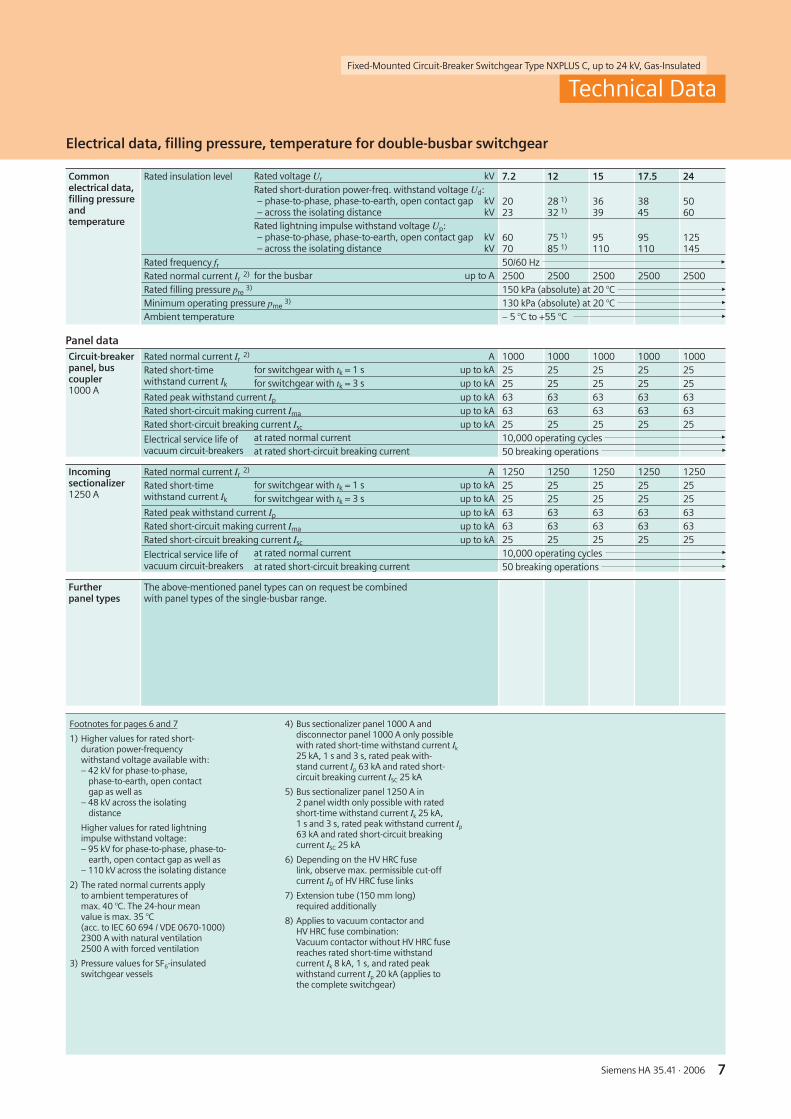
Electrical data, filling pressure, temperature for double-busbar switchgear
Commonelectrical data,filling pressureandtemperature
Rated insulation level Rated voltage Ur kV 7.2 12 15 17.5 24Rated short-duration power-freq. withstand voltage Ud:– phase-to-phase, phase-to-earth, open contact gap kV– across the isolating distance kV
2023
28 1)
32 1)3639
3845
5060
Rated lightning impulse withstand voltage Up:– phase-to-phase, phase-to-earth, open contact gap kV– across the isolating distance kV
6070
75 1)
85 1)95110
95110
125145
Rated frequency fr 50/60 HzRated normal current Ir
2) for the busbar up to A 2500 2500 2500 2500 2500Rated filling pressure pre
3) 150 kPa (absolute) at 20 °CMinimum operating pressure pme
3) 130 kPa (absolute) at 20 °CAmbient temperature – 5 °C to +55 °C
Panel dataCircuit-breakerpanel, buscoupler1000 A
Rated normal current Ir2) A 1000 1000 1000 1000 1000
Rated short-timewithstand current Ik
for switchgear with tk = 1 s up to kA 25 25 25 25 25for switchgear with tk = 3 s up to kA 25 25 25 25 25
Rated peak withstand current Ip up to kA 63 63 63 63 63Rated short-circuit making current Ima up to kA 63 63 63 63 63Rated short-circuit breaking current Isc up to kA 25 25 25 25 25
Electrical service life ofvacuum circuit-breakers
at rated normal current 10,000 operating cyclesat rated short-circuit breaking current 50 breaking operations
Incomingsectionalizer1250 A
Rated normal current Ir2) A 1250 1250 1250 1250 1250
Rated short-timewithstand current Ik
for switchgear with tk = 1 s up to kA 25 25 25 25 25for switchgear with tk = 3 s up to kA 25 25 25 25 25
Rated peak withstand current Ip up to kA 63 63 63 63 63Rated short-circuit making current Ima up to kA 63 63 63 63 63Rated short-circuit breaking current Isc up to kA 25 25 25 25 25
Electrical service life ofvacuum circuit-breakers
at rated normal current 10,000 operating cyclesat rated short-circuit breaking current 50 breaking operations
Furtherpanel types
The above-mentioned panel types can on request be combinedwith panel types of the single-busbar range.
8 Siemens HA 35.41 · 2006
Fixed-Mounted Circuit-Breaker Switchgear Type NXPLUS C, up to 24 kV, Gas-Insulated��������������������������������������������������� � ������������������������������������� � � ��������������� ������������������������������������������������ ����
���
���
�
����
���
������
�����
��� ��������������������������������������������������� � ������������������������������ � ����������������� �
����
����
��
�
��
���
����
����
���
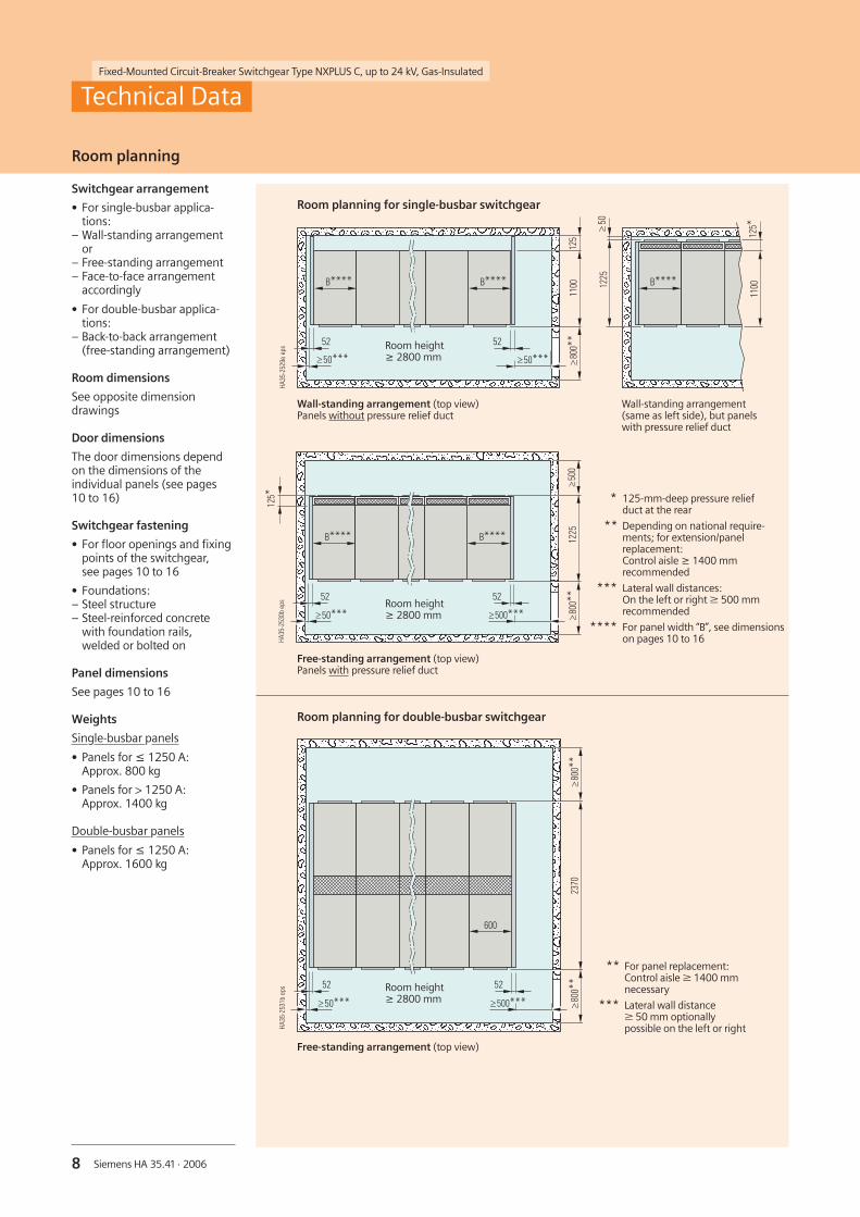
** For panel replacement:Control aisle W 1400 mmnecessary
*** Lateral wall distanceW 50 mm optionallypossible on the left or right
Room planning for double-busbar switchgear��������������������������������������������������� � ������������������������������ � ����������� � �� ����� ������������������������������������������ ����
����
����
��� ����
����
���
Free-standing arrangement (top view)
* 125-mm-deep pressure reliefduct at the rear
** Depending on national require-ments; for extension/panelreplacement:Control aisle ≥ 1400 mmrecommended
*** Lateral wall distances:On the left or right W 500 mmrecommended
**** For panel width “B”, see dimensionson pages 10 to 16
Room height≥ 2800 mm
Room planning
Technical Data
Switchgear arrangement
• For single-busbar applica-tions:
– Wall-standing arrangementor
– Free-standing arrangement– Face-to-face arrangement
accordingly
• For double-busbar applica-tions:
– Back-to-back arrangement(free-standing arrangement)
Room dimensions
See opposite dimensiondrawings
Door dimensions
The door dimensions dependon the dimensions of theindividual panels (see pages10 to 16)
Switchgear fastening
• For floor openings and fixingpoints of the switchgear,see pages 10 to 16
• Foundations:– Steel structure– Steel-reinforced concrete
with foundation rails,welded or bolted on
Panel dimensions
See pages 10 to 16
Weights
Single-busbar panels
• Panels for ≤ 1250 A:Approx. 800 kg
• Panels for > 1250 A:Approx. 1400 kg
Double-busbar panels
• Panels for ≤ 1250 A:Approx. 1600 kg
Wall-standing arrangement (top view)Panels without pressure relief duct
Room planning for single-busbar switchgear
Wall-standing arrangement(same as left side), but panelswith pressure relief duct
Free-standing arrangement (top view)Panels with pressure relief duct
Room height≥ 2800 mm
Room height≥ 2800 mm

9Siemens HA 35.41 · 2006
Fixed-Mounted Circuit-Breaker Switchgear Type NXPLUS C, up to 24 kV, Gas-Insulated
Transport
NXPLUS C switchgear is deliver-ed in form of individual panels.
The following must be noted:
• Transport facilities on site
• Transport dimensions andweights
• Size of door openings inbuilding
In case of double-busbar panelsthe A and B sides are suppliedseparately.
Packing
Place of destination insideGermany or other Europeancountries
• Method of transport:Rail and truck
• Type of packing:– Panels on open pallets– Open packing with PE
protective foil
Place of destination overseas
• Method of transport:Ship
• Type of packing:– Panels on open pallets– In closed crates with sealed
upper and lower PEprotective foil
– With desiccant bags– With sealed wooden floor– Max. storage time: 6 months
Shipping data, classification
Technical Data
1) Average values depending onthe degree to which panels areequipped
2) The loss of service continuity cate-gory always refers to the completeswitchgear, i.e. the panel with thelowest category determines theloss of service continuity categoryof the complete switchgear.
Transport dimensions, transport weights 1)
Panel width
mm
Transport dimensionsWidth x Height x Depth
mm x mm x mm
Transport weightwith packing without packing
approx. kg approx. kg
Single-busbar switchgearTransport inside Germany or to other European countries
1 x 600 1100 x 2470 x 1450 900 800
1 x 1200 1450 x 2470 x 1450 1500 1400
1 x 600 (cable connection top rear) 1100 x 2470 x 2100 900 800
Transport overseas
1 x 600 1130 x 2650 x 1450 900 800
1 x 1200 1480 x 2650 x 1450 1500 1400
1 x 600 (cable connection top rear) 1130 x 2650 x 2100 900 800
Double-busbar switchgearTransport inside Germany or to other European countries
1 x 600 1100 x 2470 x 1450 900 800
Transport overseas
1 x 600 1130 x 2650 x 1450 900 800
Classification of the NXPLUS C switchgear according to IEC 62 271-200
Internal arc classification
Class– Free-standing arrangement– Wall-standing arrangement
7.2 kV, 12 kV, 15 kVIAC A FLR 31.5 kA, 1 sIAC A FL 31.5 kA, 1 s
17.5 kV, 24 kVIAC A FLR 25 kA, 1 sIAC A FL 25 kA, 1 s
Degree of accessibility A
– F– L– R
Switchgear in closed electrical service location,access only for properly instructed personnelFrontLateralRear
Test current 25 kA, 31.5 kA
Test duration 1 s
Construction and design
Partition class PM
Loss of service continuity category 2)
Panels– Without HV HRC fuses– With HV HRC fuses
LSC 2BLSC 2A
Accessibility to compartments– Busbar compartment– Switching-device compartment– Low-voltage compartment– Cable connection compartment– Without HV HRC fuses– With HV HRC fuses
Tool-basedNot accessibleTool-based
Tool-basedInterlock-based and tool-based
10 Siemens HA 35.41 · 2006
Fixed-Mounted Circuit-Breaker Switchgear Type NXPLUS C, up to 24 kV, Gas-Insulated
����
���
�����������
��������
���
���
���
���
����
���
���
�����
��
��
�
�
��
�
���
�������
���
����
����
���
�������
����
����
���
���
�������
����
����
���
���
�������
����
���
����
����
���
���
�����������
��������
���
���
����
��
��
�
�
�
��
�
���
����
���
���
���
����
���� ���
����
���
����
����
���
����
������������
���������
���
���
���
���
����
���
���
�����
��
��
�
�
��
�
���
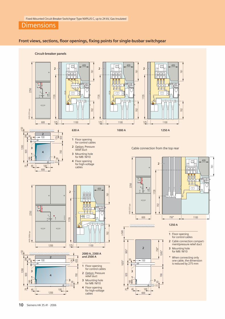
1250 A
2000 A, 2300 Aand 2500 A
1 Floor openingfor control cables
2 Option: Pressurerelief duct
3 Mounting holefor M8 / M10
4 Floor openingfor high-voltagecables
1 Floor openingfor control cables
2 Option: Pressurerelief duct
3 Mounting holefor M8 / M10
4 Floor openingfor high-voltagecables
1 Floor openingfor control cables
2 Cable connection compart-ment/pressure relief duct
3 Mounting holefor M8 / M10
* When connecting onlyone cable, the dimensionis reduced by 275 mm
Dimensions
Front views, sections, floor openings, fixing points for single-busbar switchgear
Circuit-breaker panels
Cable connection from the top rear
630 A 1000 A 1250 A
�������
����
���
����
����
���
���
������������
��������
���
���
���
���
����
���
���
�����
��
��
�
�
��
�
���
�������
���
����
����
���
���� ���
����
���
����
����
���
����
������������
���������
���
���
���
���
����
���
���
�����
��
��
�
�
��
�
���
Fixed-Mounted Circuit-Breaker Switchgear Type NXPLUS C, up to 24 kV, Gas-Insulated
11Siemens HA 35.41 · 2006
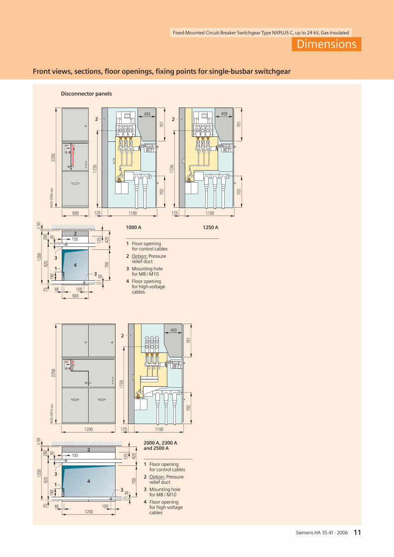
Disconnector panels
2000 A, 2300 Aand 2500 A
1 Floor openingfor control cables
2 Option: Pressurerelief duct
3 Mounting holefor M8 / M10
4 Floor openingfor high-voltagecables
1 Floor openingfor control cables
2 Option: Pressurerelief duct
3 Mounting holefor M8 / M10
4 Floor openingfor high-voltagecables
Dimensions
Front views, sections, floor openings, fixing points for single-busbar switchgear
1000 A 1250 A
�������
����
����
����
���
���
��������
���
���
���
���
����
���
���
�����
��
�
�
�
����
���������
�������
����
����
����
���
���
�
���
Fixed-Mounted Circuit-Breaker Switchgear Type NXPLUS C, up to 24 kV, Gas-Insulated
12 Siemens HA 35.41 · 2006
���������
���
���
���
���
����
���
���
�����
��
�
�
�
��
�
���
������������
���� ���
����
����
����
���
����
������������
���� ���
����
����
����
���
����
���������
���
���
���
���
����
���
���
�����
��
�
�
�
��
�
���
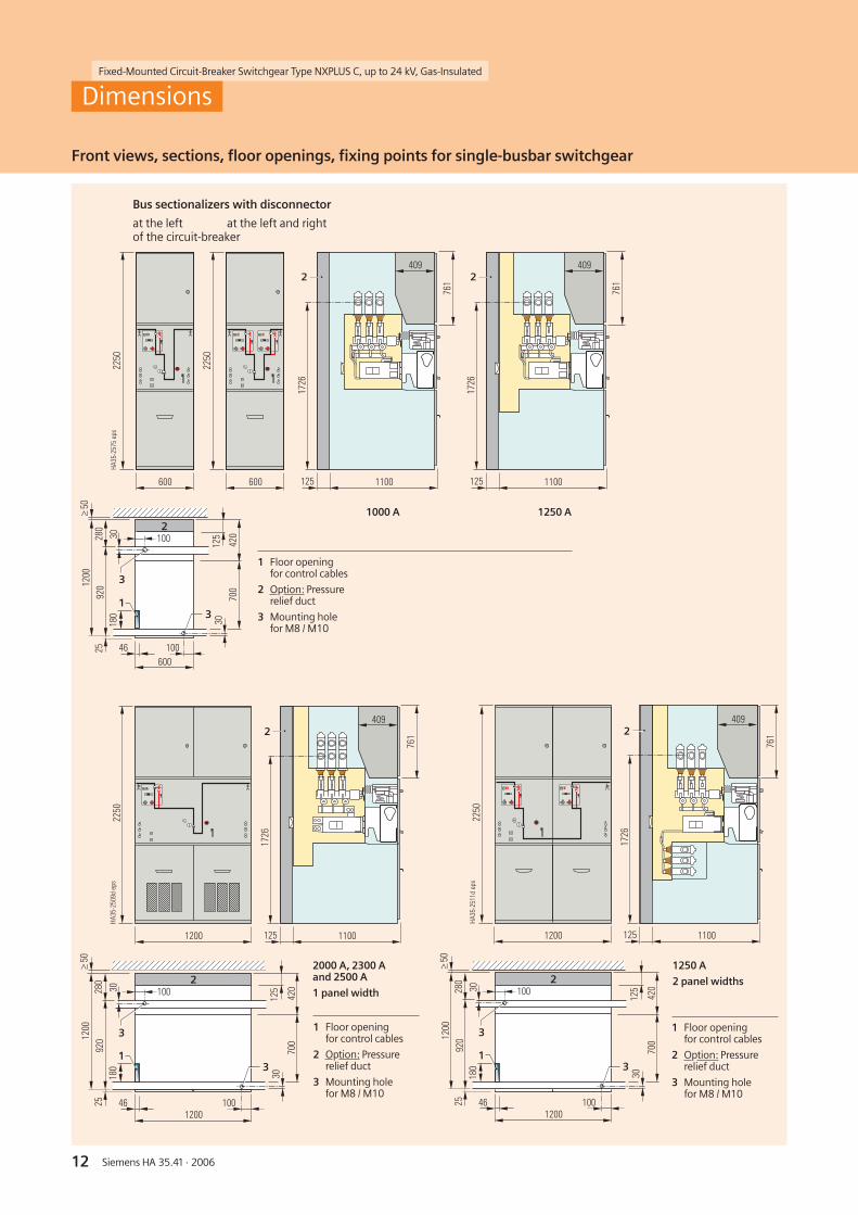
1250 A
2 panel widths
2000 A, 2300 Aand 2500 A
1 panel width
1 Floor openingfor control cables
2 Option: Pressurerelief duct
3 Mounting holefor M8 / M10
1 Floor openingfor control cables
2 Option: Pressurerelief duct
3 Mounting holefor M8 / M10
Front views, sections, floor openings, fixing points for single-busbar switchgear
Dimensions
1000 A 1250 A
1 Floor openingfor control cables
2 Option: Pressurerelief duct
3 Mounting holefor M8 / M10
Bus sectionalizers with disconnector
at the left at the left and rightof the circuit-breaker
Fixed-Mounted Circuit-Breaker Switchgear Type NXPLUS C, up to 24 kV, Gas-Insulated
13Siemens HA 35.41 · 2006
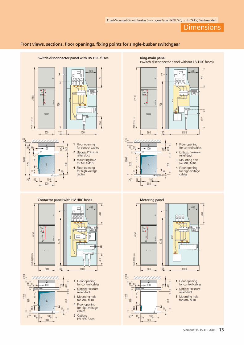
Front views, sections, floor openings, fixing points for single-busbar switchgear
Switch-disconnector panel with HV HRC fuses
��������
���
���
���
���
����
���
���
�����
��
��
�
�
����
����������
�������
����
���
����
����
���
���
�
���
������������
�����������
���
����
����
���
���
��������
���
���
���
���
����
���
���
�����
���
�
�
�
��
�
���
������������
�������
����
���
����
����
���
���
��������
���
���
���
���
����
���
���
�����
��
��
�
�
��
�
���
�
������������
�������
����
����
����
���
���
��������
���
���
���
���
����
���
���
�����
��
�
�
�
��
�
���
Ring-main panel(switch-disconnector panel without HV HRC fuses)
Contactor panel with HV HRC fuses Metering panel
1 Floor openingfor control cables
2 Option: Pressurerelief duct
3 Mounting holefor M8 / M10
4 Floor openingfor high-voltagecables
1 Floor openingfor control cables
2 Option: Pressurerelief duct
3 Mounting holefor M8 / M10
4 Floor openingfor high-voltagecables
1 Floor openingfor control cables
2 Option: Pressurerelief duct
3 Mounting holefor M8 / M10
1 Floor openingfor control cables
2 Option: Pressurerelief duct
3 Mounting holefor M8 / M10
4 Floor openingfor high-voltagecables
5 Option:HV HRC fuses
Dimensions
Fixed-Mounted Circuit-Breaker Switchgear Type NXPLUS C, up to 24 kV, Gas-Insulated
14 Siemens HA 35.41 · 2006
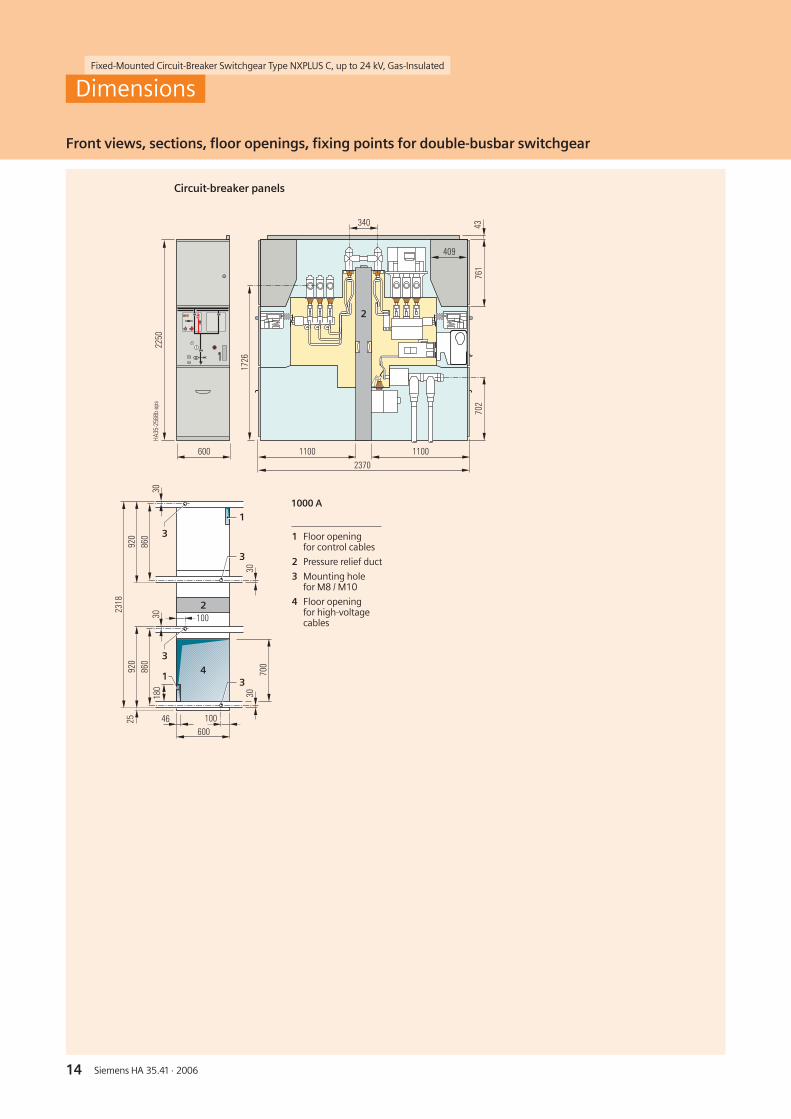
Circuit-breaker panels
��������
���
���
���
����
��
��
��
���
��
��
���
���
���
����
������������
��
����
��� ����
���
���
���
��������
���
��
��
�
�
�
�
�
1 Floor openingfor control cables
2 Pressure relief duct
3 Mounting holefor M8 / M10
4 Floor openingfor high-voltagecables
Front views, sections, floor openings, fixing points for double-busbar switchgear
Dimensions
1000 A

Fixed-Mounted Circuit-Breaker Switchgear Type NXPLUS C, up to 24 kV, Gas-Insulated
15Siemens HA 35.41 · 2006
Incoming sectionalizer
��������
���
���
���
����
��
��
��
���
��
��
���
���
���
����
����
���
���
������������
��
����
���
���
���
��������
���
��
��
�
�
�
�
�
�
1 Floor openingfor control cables
2 Pressure relief duct
3 Mounting holefor M8 / M10
4 Floor openingfor high-voltagecables
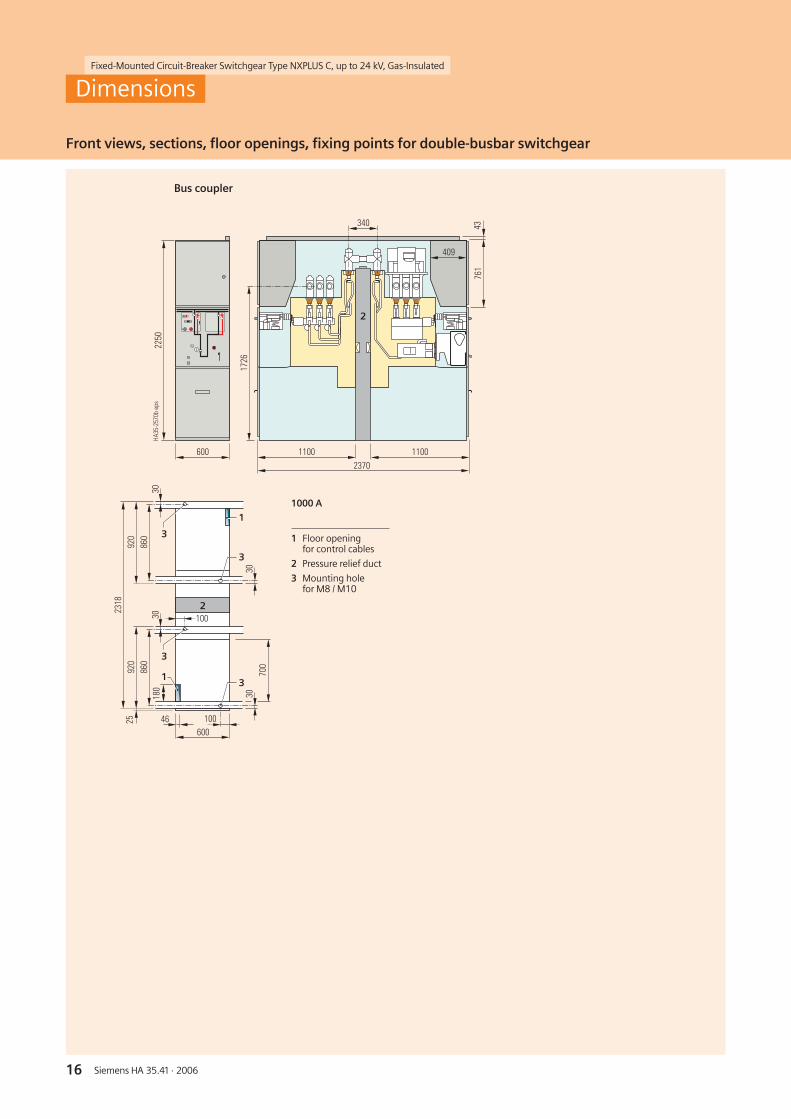
Front views, sections, floor openings, fixing points for double-busbar switchgear
Dimensions
1250 A
Fixed-Mounted Circuit-Breaker Switchgear Type NXPLUS C, up to 24 kV, Gas-Insulated
16 Siemens HA 35.41 · 2006
Bus coupler
��������
���
���
���
����
��
��
��
���
��
��
���
���
���
����
������������
����
���
���
��������
��� ��
����
���
�
��
�
�
�
�
�
1 Floor openingfor control cables
2 Pressure relief duct
3 Mounting holefor M8 / M10
Front views, sections, floor openings, fixing points for double-busbar switchgear
Dimensions
1000 A
Fixed-Mounted Circuit-Breaker Switchgear Type NXPLUS C, up to 24 kV, Gas-Insulated
17Siemens HA 35.41 · 2006
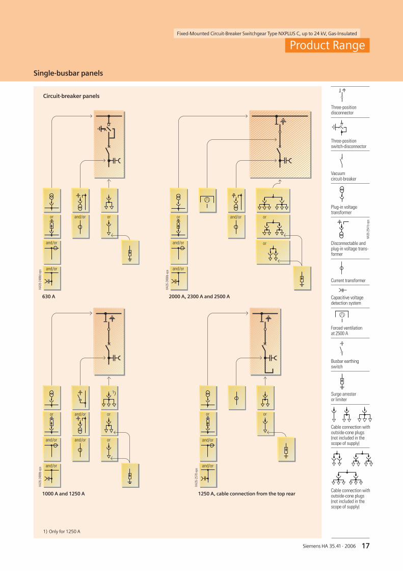
Circuit-breaker panels
1) Only for 1250 A
������������
�������� ��
������
������
������������
������ ��
��
��
������
������
������������
��
������ ����
������ ��������
������
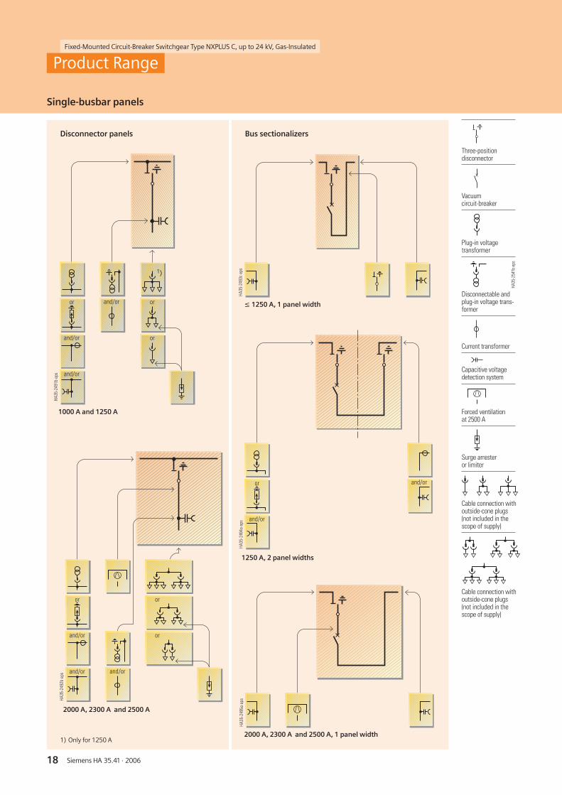
Single-busbar panels
Product Range
1250 A, cable connection from the top rear
����
����
��
�
������
��
������
��
2000 A, 2300 A and 2500 A
1000 A and 1250 A
630 A
Vacuumcircuit-breaker
Three-positionswitch-disconnector
Three-positiondisconnector
Capacitive voltagedetection system
Disconnectable andplug-in voltage trans-former
Forced ventilationat 2500 A
Busbar earthingswitch
Plug-in voltagetransformer
Current transformer
Surge arresteror limiter
Cable connection withoutside-cone plugs(not included in thescope of supply)
Cable connection withoutside-cone plugs(not included in thescope of supply)
HA35
-254
1bep
s
Fixed-Mounted Circuit-Breaker Switchgear Type NXPLUS C, up to 24 kV, Gas-Insulated
18 Siemens HA 35.41 · 2006
������������
��
��
������
������
������ ��
��
������������
������������
��
������
������ ������
��
��
������������
��
������
������
������������
Single-busbar panels
Disconnector panels Bus sectionalizers
Product Range
1000 A and 1250 A
1250 A, 2 panel widths
≤ 1250 A, 1 panel width
2000 A, 2300 A and 2500 A
2000 A, 2300 A and 2500 A, 1 panel width1) Only for 1250 A
Three-positiondisconnector
Capacitive voltagedetection system
Disconnectable andplug-in voltage trans-former
Forced ventilationat 2500 A
Plug-in voltagetransformer
Vacuumcircuit-breaker
Current transformer
Surge arresteror limiter
Cable connection withoutside-cone plugs(not included in thescope of supply)
Cable connection withoutside-cone plugs(not included in thescope of supply)
HA35
-254
1bep
s

Fixed-Mounted Circuit-Breaker Switchgear Type NXPLUS C, up to 24 kV, Gas-Insulated
19Siemens HA 35.41 · 2006
Ring-main panel
Contactor panel Metering panel
Single-busbar panels
Product Range
Switch-disconnector panel
1) Only possible when contactor panelis designed without fuse
Contactor panel
2)
����
����
����
��
��
������
������
�� ������
����
����
����
��
������
������
������������
��
������
������
��
����
����
����
��
������
������
��������
Plug-in voltagetransformer
Vacuum contactor
HV HRC fuses
Three-positionswitch-disconnector
Cable connection withoutside-cone plugs(not included in thescope of supply)
Surge arresteror limiter
Capacitive voltagedetection system
Disconnectable andplug-in voltage trans-former
Current transformer
2nd earthingswitch for fuses
HA35
-254
1bep
s

20 Siemens HA 35.41 · 2006
Fixed-Mounted Circuit-Breaker Switchgear Type NXPLUS C, up to 24 kV, Gas-Insulated
Circuit-breaker panels Incoming sectionalizer
Single-busbar panel, prepared for laterextension to double-busbar panel: Bus coupler
Double-busbar panels
Product Range��
����������
������
��
������
������
��������
��
��
������
������
������������
������
��
������
������
��
��
��
������
������
1250 A1000 A
������������
������
��
������
������
��
������
������
1000 A
������������
��
������
������
��
��
������
1000 A
Abbreviations
SS1 = Busbar 1SS2 = Busbar 2
Three-positiondisconnector
Capacitive voltagedetection system
Disconnectable andplug-in voltage trans-former
Plug-in voltagetransformer,mounted separately
Current transformer
Surge arresteror limiter
Vacuumcircuit-breaker
Cable connection withoutside-cone plugs(not included in thescope of supply)
Panel bars
Plug-in voltagetransformer
HA35
-254
1bep
s

21Siemens HA 35.41 · 2006
Fixed-Mounted Circuit-Breaker Switchgear Type NXPLUS C, up to 24 kV, Gas-Insulated
������������
�
�
�
��
��
��
�
�
��
��
��
��
��
��
��
�
��
��
�
��
��
��
��
��
�
�
��
��
��
���
�
��
��
�
Basic panel design
Design
Insulating system
• Switchgear vessel filled with SF6-gas
• Features of SF6-gas:– Non-toxic– Odourless and colourless– Non-inflammable– Inert– Heavier than air– Electronegative (high-quality
insulator)
• Pressure of SF6-gas in theswitchgear vessel (absolute values):
– Rated filling pressure: 150 kPa– Design pressure: 180 kPa– Design temperature
of SF6-gas: 80 °C– Operating pressure of rupture
diaphragm: ≥ 300 kPa– Bursting pressure: ≥ 550 kPa
Panel design
• Factory-assembled, type-tested
• Metal-enclosed, metal-clad
• Hermetically welded switchgearvessel made of stainless steel,without seals
• Single-pole, solid-insulated,screened busbars, plug-in type
• Maintenance-free
• Degree of protection– IP 65 for all high-voltage parts
of the primary circuit– IP 3XD for the switchgear enclosure
• Vacuum circuit-breaker orvacuum contactor
• Three-position disconnector fordisconnecting and earthing bymeans of the circuit-breaker
• Make-proof earthing by meansof the vacuum circuit-breaker
• Three-position switch-disconnector
• Cable connection withoutside-cone plug-in systemaccording to DIN EN 50 181
• Wall-standing or free-standingarrangement
• Installation and possible later exten-sion of existing panels without gaswork
• Replacement of switchgear vesselwithout gas work
• Replacement of instrument trans-formers without gas work, as theyare mounted outside the gascompartments
• Enclosure made of galvanized sheet-steel, front cover, rear cover and endwalls painted in colour ”light basic”(SN 700)
• Low-voltage compartment remov-able, plug-in bus wires
• Lateral, metallic wiring ducts forcontrol cables
Circuit-breaker panel (example)
Front view
Detail Z:
Sectional view (cable connection from the front)
1 Low-voltagecompartment
2 Multifunction protectionrelay SIPROTEC 4 (example)
3 Switch position indicationfor circuit-breaker
4 Actuating opening forcharging the circuit-breaker springs
5 ON pushbutton forcircuit-breaker
6 ”Spring charged”indication
7 Operating cycle counterfor circuit-breaker
8 Switch position indicationfor ”disconnecting”function of three-positionswitch
9 Ready-for-serviceindication
10 Switch positionindication for ”ready-to-earth” function ofthree-position switch
11 Control gate andlocking device for”disconnecting/earthing”functions of three-position switch
12 Interrogation lever
13 Actuating openingfor ”disconnecting”function of three-positionswitch
14 Actuating openingfor ”ready-to-earth”function of three-positionswitch
15 Option: Busbar voltagetransformer, plug-in type
16 Busbars, single-pole,fully-insulated, plug-intype, earthed on theoutside
17 Option: Busbar currenttransformer
18 Switchgear vessel,hermetically welded,filled with SF6-gas
19 Three-positiondisconnector
20 OFF pushbutton forcircuit-breaker
21 Vacuum interrupter ofcircuit-breaker
22 Pressure relief(rupture diaphragm)
23 Capacitive voltagedetection system
24 Locking device for feeder(suitable for locking withpadlock)
25 Disconnecting facility forfeeder voltage transformer
26 Bushing for feeder voltagetransformer
27 Option: Feeder voltagetransformer
28 Option: Pressure relief duct
29 Cable connectioncompartment
30 Operating mechanism forthree-position switch
31 Operating mechanism forcircuit-breaker
32 Feeder current transformer
33 Cable connection withoutside-cone T-plug
34 Operation of disconnectingfacility of the feeder voltagetransformer
35 Earthing busbar withearthing connection
36 Air guides cable connection
22 Siemens HA 35.41 · 2006
Fixed-Mounted Circuit-Breaker Switchgear Type NXPLUS C, up to 24 kV, Gas-Insulated
Vacuum circuit-breaker
����
����
����
�� �� �� �� � � ��
��
R-HA
35-0
50ep
s
7
8
9
10
11
6
5
4
3
2
1
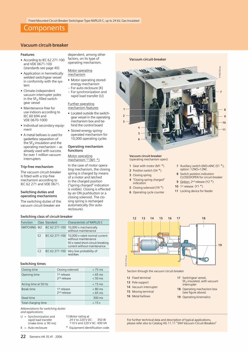
Vacuum circuit-breaker
Components
Features
• According to IEC 62 271-100and VDE 0671-100(standards see page 40)
• Application in hermeticallywelded switchgear vesselin conformity with the sys-tem
• Climate-independentvacuum interrupter polesin the SF6-filled switch-gear vessel
• Maintenance-free foruse indoors according toIEC 60 694 andVDE 0670-1000
• Individual secondary equip-ment
• A metal bellows is used forgasketless separation ofthe SF6-insulation and theoperating mechanism – asalready used with successfor over 1 million vacuuminterrupters
Trip-free mechanism
The vacuum circuit-breakeris fitted with a trip-freemechanism according toIEC 62 271 and VDE 0671.
Switching duties andoperating mechanisms
The switching duties of thevacuum circuit-breaker are
dependent, among otherfactors, on its type ofoperating mechanism.
Motor operatingmechanism
• Motor operating stored-energy mechanism
– For auto-reclosure (K)– For synchronization and
rapid load transfer (U)
Further operatingmechanism features
• Located outside the switch-gear vessel in the operatingmechanism box and be-hind the control board
• Stored-energy spring-operated mechanism for10,000 operating cycles
Operating mechanismfunctions
Motor operatingmechanism 1) (M1 *)
In the case of motor opera-ting mechanism, the closingspring is charged by meansof a motor and latchedin the charged position(”spring charged” indicationis visible). Closing is effectedby an ON pushbutton or aclosing solenoid. The clo-sing spring is rechargedautomatically (for auto-reclosure).
Abbreviations for switching dutiesand applications:
U = Synchronization andrapid load transfer(make time ≤ 90 ms)
K = Auto-reclosure
1) Motor rating at24 V to 220 V DC: 350 W110 V and 220 V AC: 400 VA
* Equipment identification code
For further technical data and description of typical applications,please refer also to Catalog HG 11.11 ”3AH Vacuum Circuit-Breakers”
12 Fixed terminal
13 Pole support
14 Vacuum interrupter
15 Moving terminal
16 Metal bellows
17 Switchgear vessel,SF6-insulated, with vacuuminterrupter
18 Operating mechanism box(see figure above)
19 Operating kinematics
Section through the vacuum circuit-breaker
Vacuum circuit-breaker(operating mechanism open)
1 Gear with motor (M1 *)
2 Position switch (S4 *)
3 Closing spring
4 ”Closing spring charged”indication
5 Closing solenoid (Y9 *)
6 Operating cycle counter
7 Auxiliary switch 6NO+6NC (S1 *),option: 12NO+12NC
8 Switch position indicationCLOSED/OPEN for circuit-breaker
9 Option: 2nd release (Y2 *)
10 1st release (Y1 *)
11 Locking device for feeder
Switching class of circuit-breaker
Function Class Standard Characteristic of NXPLUS C
SWITCHING M2 IEC 62 271-100 10,000 x mechanicallywithout maintenance
E2 IEC 62 271-100 10,000 x rated normal currentwithout maintenance50 x rated short-circuit breakingcurrent without maintenance
C2 IEC 62 271-100 Very low probability ofrestrikes
Switching times
Closing time Closing solenoid < 75 ms
Opening time 1st release2nd release
< 65 ms< 50 ms
Arcing time at 50 Hz < 15 ms
Break time 1st release2nd release
< 80 ms< 65 ms
Dead time 300 ms
Total charging time < 15 s
23Siemens HA 35.41 · 2006
Fixed-Mounted Circuit-Breaker Switchgear Type NXPLUS C, up to 24 kV, Gas-Insulated
Vacuum circuit-breaker
�����
�����
����
����
����
���
��
��
��
���
���
�� �� ����� � ���
����
����
��
�
Perm
issi
ble
oper
atin
gcy
cles
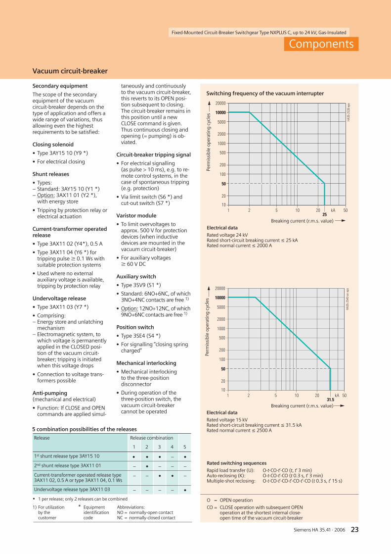
Rated switching sequences
Rapid load transfer (U): O-t-CO-t'-CO (t, t' 3 min)Auto-reclosing (K): O-t-CO-t'-CO (t 0.3 s, t' 3 min)Multiple-shot reclosing: O-t-CO-t'-CO-t'-CO-t'-CO (t 0.3 s, t' 15 s)
�����
�����
����
����
����
���
��
��
��
���
���
�� �� ����� � �����
����
����
���
��
5 combination possibilities of the releases
Release Release combination
1 2 3 4 5
1st shunt release type 3AY15 10 • • • – •
2nd shunt release type 3AX11 01 – • – – –
Current-transformer operated release type3AX11 02, 0.5 A or type 3AX11 04, 0.1 Ws
– – • • –
Undervoltage release type 3AX11 03 – – – – •
• 1 per release; only 2 releases can be combined
Components
taneously and continuouslyto the vacuum circuit-breaker,this reverts to its OPEN posi-tion subsequent to closing.The circuit-breaker remains inthis position until a newCLOSE command is given.Thus continuous closing andopening (= pumping) is ob-viated.
Circuit-breaker tripping signal
• For electrical signalling(as pulse > 10 ms), e.g. to re-mote control systems, in thecase of spontaneous tripping(e.g. protection)
• Via limit switch (S6 *) andcut-out switch (S7 *)
Varistor module
• To limit overvoltages toapprox. 500 V for protectiondevices (when inductivedevices are mounted in thevacuum circuit-breaker)
• For auxiliary voltagesW 60 V DC
Auxiliary switch
• Type 3SV9 (S1 *)
• Standard: 6NO+6NC, of which3NO+4NC contacts are free 1)
• Option: 12NO+12NC, of which9NO+6NC contacts are free 1)
Position switch
• Type 3SE4 (S4 *)
• For signalling ”closing springcharged”
Mechanical interlocking
• Mechanical interlockingto the three-positiondisconnector
• During operation of thethree-position switch, thevacuum circuit-breakercannot be operated
Secondary equipment
The scope of the secondaryequipment of the vacuumcircuit-breaker depends on thetype of application and offers awide range of variations, thusallowing even the highestrequirements to be satisfied:
Closing solenoid
• Type 3AY15 10 (Y9 *)
• For electrical closing
Shunt releases
• Types:– Standard: 3AY15 10 (Y1 *)– Option: 3AX11 01 (Y2 *),
with energy store
• Tripping by protection relay orelectrical actuation
Current-transformer operatedrelease
• Type 3AX11 02 (Y4*), 0.5 A
• Type 3AX11 04 (Y6 *) fortripping pulse W 0.1 Ws withsuitable protection systems
• Used where no externalauxiliary voltage is available,tripping by protection relay
Undervoltage release
• Type 3AX11 03 (Y7 *)
• Comprising:– Energy store and unlatching
mechanism– Electromagnetic system, to
which voltage is permanentlyapplied in the CLOSED posi-tion of the vacuum circuit-breaker; tripping is initiatedwhen this voltage drops
• Connection to voltage trans-formers possible
Anti-pumping(mechanical and electrical)
• Function: If CLOSE and OPENcommands are applied simul-
1) For utilizationby thecustomer
Abbreviations:NO = normally-open contactNC = normally-closed contact
* Equipmentidentificationcode
Switching frequency of the vacuum interrupter
Electrical data
Rated voltage 24 kVRated short-circuit breaking current ≤ 25 kARated normal current ≤ 2000 A
Breaking current (r.m.s. value)
Perm
issi
ble
oper
atin
gcy
cles
Breaking current (r.m.s. value)Electrical data
Rated voltage 15 kVRated short-circuit breaking current ≤ 31.5 kARated normal current ≤ 2500 A
O = OPEN operation
CO = CLOSE operation with subsequent OPENoperation at the shortest internal close-open time of the vacuum circuit-breaker

24 Siemens HA 35.41 · 2006
Fixed-Mounted Circuit-Breaker Switchgear Type NXPLUS C, up to 24 kV, Gas-Insulated
R-HA
35-0
47ep
sR-
HA35
-040
aep
s
4
3
2
1
5
6
7
8
�����������
����
����
��
�
8
9
Components
Three-position switch
Common features
• According toIEC 62 271-102 andVDE 0671-102(standards see page 40)
• Application in hermeti-cally welded switchgearvessel in conformity withthe system
• Climate-independentswitching elements inthe SF6-filled switchgearvessel
• Maintenance-free foruse indoors according toIEC 60 694 andVDE 0670-1000
• Individual secondaryequipment
• A metal bellows is usedfor gasketless separationof the SF6-insulation andthe operating mecha-nism – as already usedwith success for over1 million vacuum inter-rupters
• Compact design due toshort contact gaps inSF6-gas
• Operation via gas-tightwelded metal bellows atthe front of the switch-gear vessel
• Reliable switch positionup to the operating frontof the panel
Three-positiondisconnector
• Application in– Circuit-breaker panel from
1000 A to 2500 A (withinterlock against thecircuit-breaker)
– Disconnector panel from1000 A to 2500 A
– Bus sectionalizer from1000 A to 2500 A
• 1000 mechanical operat-ing cycles for CLOSED /OPEN / READY-TO-EARTH
Three-positionswitch-disconnector
• Application in– Circuit-breaker panel 630 A
(as disconnector withinterlock against thecircuit-breaker)
– Switch-disconnector panel– Ring-main panel– Contactor panel– Metering panel
• 1000 mechanical operat-ing cycles for CLOSED /OPEN / EARTHED
• Switching functions asgeneral-purpose switch-disconnector according to
– IEC 60 265-1– VDE 0670-301– IEC 62 271-102– VDE 0671-102
(Standards see page 40)
• Designed as a multi-cham-ber switch incorporatingthe functions
– Switch-disconnector and– Make-proof earthing
switch
• Additional switch-discon-nector functions:
– 10 closing operations atrated short-circuit makingcurrent (demandedaccording to IEC / VDE:2 closing operations)
– 100 operating cycles atrated normal current
Switch positions of the three-position switches
Three-position disconnector(in OPEN position)with vacuum circuit-breaker arranged below(view into the switchgear vessel opened at the rear)
1 Fixed contact at the busbar
2 Swinging contact blade
3 Fixed contact for ”feeder EARTHED”
4 Operating shaft
CLOSED
OPEN
FeederEARTHED
Switch positions
Three-position switch-disconnector(exploded view)
5 Fixed contacts to earth
6 Rotary contact blade
7 Operating shaft
8 Fixed contact to the feeder
9 Fixed contact to the busbar
CLOSED
OPEN
FeederEARTHED
Switch positions

25Siemens HA 35.41 · 2006
Fixed-Mounted Circuit-Breaker Switchgear Type NXPLUS C, up to 24 kV, Gas-Insulated
����
����
��
�
�
�
����
����
��
�
�
�
1) By closing the circuit-breaker
Components
Three-position switch
Interlocks
• Selection of permissibleswitching operations bymeans of a control gatewith mechanically inter-locked vacuum circuit-breaker
• Corresponding operatingshafts are not releasedat the operating frontuntil they have been pre-selected with the controlgate
• Operating lever cannotbe removed until switch-ing operation has beencompleted
• Circuit-breaker cannot beclosed until control gate isin neutral position again
• Switchgear interlockingsystem also possible withelectromechanical inter-locks if switchgear isequipped with motoroperating mechanisms(mechanical interlockingfor manual operation re-mains)
Switch positions
• ”CLOSED”, ”OPEN”,”EARTHED” or“READY-TO-EARTH”
• In circuit-breaker panels,the cable connection isearthed and short-circuited by closing thevacuum circuit-breaker
Operating mechanism
• Spring-operated mecha-nism operated via operat-ing lever at the operatingfront of the panel
• Separate operating shaftsfor the functionsDISCONNECTING andEARTHING or READY-TO-EARTH
• Option: Motor operatingmechanism for the func-tions DISCONNECTING andEARTHING or READY-TO-EARTH
• Spring-operated/stored-energy mechanism for theswitch-disconnector func-tion with fuses:Opening spring pre-charged (after closing)
• Maintenance-free due tonon-rusting design ofparts subjected tomechanical stress
• Bearings which require nolubrication
Transmission principle foroperating mechanisms(see opposite drawings)
• Transmission of operatingpower from outside intothe gas-filled switchgearvessel by means of a metalbellows
• Gas-tight
• Maintenance-free
Transmission principle for operating mechanisms
Three-positiondisconnector
1 Gas-filled switchgear vessel
2 Gas-tight welded metal bellows
Three-positionswitch-disconnector
1 Gas-filled switchgear vessel
2 Gas-tight welded metal bellows
Switching class of three-position disconnector
Function Class Standard Characteristic of NXPLUS C
DISCONNECTING M0 IEC 62 271-102
1000 x mechanicallywithout maintenance
READY-TO-EARTH
1000 x mechanicallywithout maintenance
EARTHING E2 1) IEC 62 271-102
50 x rated short-circuitmaking current Imawithout maintenance
Switching class of three-position switch-disconnector
Function Class Standard Characteristic of NXPLUS C
DISCONNECTING M0 IEC 62 271-102
1000 x mechanicallywithout maintenance
LOADSWITCHING
M1
E3
IEC 60 265-1
IEC 60 265-1
1000 x mechanicallywithout maintenance100 x rated mainly activeload breaking current I1without maintenance
5 x rated short-circuitmaking current Imawithout maintenance
EARTHING E2 IEC 62 271-102
5 x rated short-circuitmaking current Imawithout maintenance

26 Siemens HA 35.41 · 2006
Fixed-Mounted Circuit-Breaker Switchgear Type NXPLUS C, up to 24 kV, Gas-Insulated
�� �
� �
� ��
������
��
���
������
��
�
Components
HV HRC fuse assembly
Features
• Application in– Switch-disconnector
panel– Contactor panel– Metering panel
• HV HRC fuse linksaccording to DIN 43 625(main dimensions) withstriker pin in ”medium”version acc. to IEC 60 282 /VDE 0670-4
– As short-circuit protectionbefore transformers inthe switch-disconnectorpanel
– As short-circuit protectionbefore motors in thecontactor panel
– As short-circuit protectionbefore voltage trans-formers in the meteringpanel
– With selectivity(depending on correctselection) to upstreamand downstreamconnected equipment
– Single-pole insulated
• Requirements accordingto IEC 62 271-105 andVDE 0671-105 fulfilledby combination of HVHRC fuses with thethree-position switch-disconnector
• Climate-independent andmaintenance-free, withfuse boxes made of castresin
• Fuse assembly connectedto the three-positionswitch-disconnector viawelded bushings andconnecting bars
• Location of fuse assemblybelow the switchgearvessel
• Fuse can only be replacedif feeder is earthed
• Option:“Fuse tripped” indicationfor remote electrical indi-cation with one normally-open contact (1NO)
Mode of operation
In the event that an HV HRCfuse link has tripped, theswitch is tripped via an arti-culation which is integratedinto the cover of the fusebox (see figure).
In the event that the fusetripping fails, e.g. if the fusehas been inserted incorrect-ly, the fuse box is protectedby thermal protection. Theoverpressure generated byoverheating trips the switchvia the diaphragm in thecover of the fuse box and viaan articulation. This breaksthe current before the fusebox incurs irreparabledamage.
The above thermal protec-tion works independently ofthe type and design of theHV HRC fuse used. Like thefuse itself, it is maintenance-free and independent of anyoutside climatic effects.
Furthermore, the SiemensHV HRC fuses release thestriker pin independently ofthe temperature and trip thethree-position switch-dis-connector as early as in thefuse overload range. Imper-missible heating of the fusebox can be avoided in thisway.
Replacementof HV HRC fuse links
• Isolating and earthing ofthe transformer feeder
• Subsequent manual re-placement of the HV HRCfuse link after removingthe cable compartmentcover
HV HRC fuse assembly
Basic design
1 Bushing
2 Switchgear vessel
3 Sealing cover with seal
4 Tripping pin for spring-operated/stored-energy mechanism
5 Fuse box
6 HV HRC fuse link
7 Striker pin of the HV HRC fuse link andarticulation for tripping of thespring-operated/stored-energy mechanism
Schematic sketchesfor fuse tripping
Fuse linkin service condition
Fuse trippedby striker pin
Fuse tripped by overpressure,e.g. if HV HRC fuse linkhas been inserted incorrectly
27Siemens HA 35.41 · 2006
Fixed-Mounted Circuit-Breaker Switchgear Type NXPLUS C, up to 24 kV, Gas-Insulated
Components
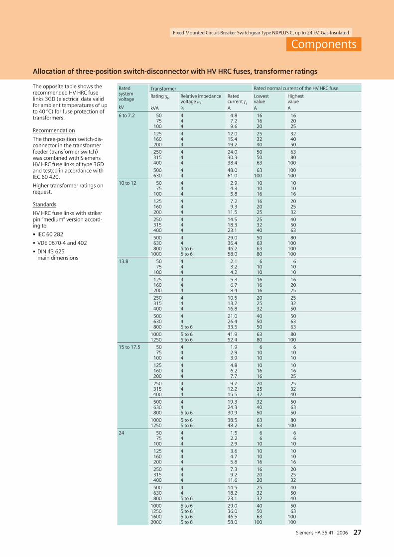
Allocation of three-position switch-disconnector with HV HRC fuses, transformer ratings
The opposite table shows therecommended HV HRC fuselinks 3GD (electrical data validfor ambient temperatures of upto 40 °C) for fuse protection oftransformers.
Recommendation
The three-position switch-dis-connector in the transformerfeeder (transformer switch)was combined with SiemensHV HRC fuse links of type 3GDand tested in accordance withIEC 60 420.
Higher transformer ratings onrequest.
Standards
HV HRC fuse links with strikerpin ”medium” version accord-ing to
• IEC 60 282
• VDE 0670-4 and 402
• DIN 43 625main dimensions
Ratedsystemvoltage
kV
Transformer Rated normal current of the HV HRC fuse
Rating SN
kVA
Relative impedancevoltage uk
%
Ratedcurrent I1
A
LowestvalueA
HighestvalueA
6 to 7.2 5075
100
444
4.87.29.6
161620
162025
125160200
444
12.015.419.2
253240
324050
250315400
444
24.030.338.4
505063
6380
100
500630
44
48.061.0
63100
100100
10 to 12 5075
100
444
2.94.35.8
101016
101016
125160200
444
7.29.3
11.5
162025
202532
250315400
444
14.518.323.1
253240
405063
500630800
1000
445 to 65 to 6
29.036.446.258.0
50636380
80100100100
13.8 5075
100
444
2.13.24.2
61010
61010
125160200
444
5.36.78.4
161616
162025
250315400
444
10.513.216.8
202532
253250
500630800
445 to 6
21.026.433.5
405050
506363
10001250
5 to 65 to 6
41.952.4
6380
80100
15 to 17.5 5075
100
444
1.92.93.9
61010
61010
125160200
444
4.86.27.7
101616
101625
250315400
444
9.712.215.5
202532
253240
500630800
445 to 6
19.324.330.9
324050
506350
10001250
5 to 65 to 6
38.548.2
6363
80100
24 5075
100
444
1.52.22.9
66
10
66
10
125160200
444
3.64.75.8
101016
101016
250315400
444
7.39.2
11.6
162020
202532
500630800
445 to 6
14.518.223.1
253232
405040
1000125016002000
5 to 65 to 65 to 65 to 6
29.036.046.558.0
405063
100
5063
100100

Fixed-Mounted Circuit-Breaker Switchgear Type NXPLUS C, up to 24 kV, Gas-Insulated
28 Siemens HA 35.41 · 2006
����
����
����
� ��� �� �� ��
5
4
32
1
�����������
���
R-HA
35-1
10ep
s
Components
Vacuum contactor, motor protection
Features
• According to IEC 60 470 andVDE 0670-501 (standards seepage 40)
• Application in hermeticallywelded switchgear vessel inconformity with the system
• Climate-independent vacuuminterrupter poles in theSF6-filled switchgear vessel
• Maintenance-free foruse indoors according toIEC 60 694 andVDE 0670-1000
• Individual secondary equip-ment
• A metal bellows is used forgasketless separation of theSF6 insulation and the oper-ating mechanism – as al-ready used with success forover 1 million vacuum inter-rupters
• Magnet coil for operationlocated outside the switch-gear vessel
• 100,000 or 500,000 operat-ing cycles at rated normalcurrent
• Option: (only with 100,000operating cycles) Electro-mechanical closing latch withelectrical unlocking
Short-circuit and overloadprotection in connection withmotors
In circuits subjected to short-circuit currents, HV HRC fuselinks protect switching deviceswithout short-circuit breakingcapacity (e.g. vacuum contac-tors).
The max. stress for HV HRCfuses arises during motorstarting (starting currents,starting times and startingfrequency).
Fuses must not operate or bepre-damaged during motorstarting.
The opposite table shows thepermissible motor starting cur-rents according to the startingtime and starting frequencyof downstream connected HVmotors with the associatedHV HRC fuses.
Vacuum contactor
Vacuum contactor(operating mechanism open)
1 Metal bellows
2 Pole support
3 Vacuum interrupter
4 Operating mechanism box with magnet coil
5 Base plate (welded into the switchgear vessel)
Section through the vacuum contactor
Motor protection table
Numberof startsper hour
Maximum permissible motor starting current in A
at rated normal current of fuse
40 A 63 A 100 A 125 A 160 A 250 A
HV motorswith starting timesup to 5 s
2 90 135 255 360 480 740
4 80 120 235 330 440 675
8 75 110 215 300 400 615
16 65 100 190 270 360 550
HV motorswith starting timesup to 15 s
2 85 120 225 310 430 635
4 75 110 205 285 400 580
8 70 100 185 260 360 530
16 60 90 165 235 325 475
HV motorswith starting timesup to 30 s
2 80 120 215 300 420 600
4 70 105 190 265 370 530
8 65 90 165 230 320 460
16 55 80 145 200 280 400
6 Fixed terminal
7 Pole support
8 Vacuum interrupter
9 Moving terminal
10 Switchgear vessel,SF6-insulated, with vacuuminterrupter
11 Metal bellows
12 Operating mechanism box(see figure above)
13 Operating kinematics

29Siemens HA 35.41 · 2006
Fixed-Mounted Circuit-Breaker Switchgear Type NXPLUS C, up to 24 kV, Gas-Insulated
����
����
����
�������������������
�
�
�
�
�
�
��
R-HA
35-0
51ep
s
�����������
�������������������������������������
�
�
�
�
�
��
�
�
�
�
�
�
�
Components
Busbars
Features
• Single-pole, plug-in design
• Consisting of round-barcopper, insulated by meansof silicone rubber
• Busbar joints with cross andend adapters, insulated bymeans of silicone rubber
• Field control by means ofelectrically conductive layerson the silicone-rubber insula-tion (both internally and ex-ternally)
• Safe-to-touch by earthingthe external layers with theswitchgear vessel
• Insensitive to pollution andcondensation
• Safe-to-touch as a result ofuse of metallic covers
• Switchgear extension orpanel replacement withoutSF6-gas work
Possible fittings
• Current transformers
• Voltage transformers
• Surge arresters
• Cables with– Straight plug or– T-plug
• Fully-insulated bars(e.g. make Duresca)
Legend
1 Cap
2 Busbar insulation made ofsilicone rubber
3 Clamps
4 Busbar (round-bar copper)
5 End adapter
6 Switchgear vessel
7 Metal cover of busbars
8 Cross adapter
9 Earthing connection
10 Bushing
Section of busbar 1250 A (basic design)(panel width 600 mm)
Plug-in busbars (example)
Section of tandem busbar 1600 A, 2000 A or 2500 A (basic design)(panel width 600 mm)
Busbars 1250 A, plug-in type, fully insulated(as front view of three panels, without low-voltage compartments)

Fixed-Mounted Circuit-Breaker Switchgear Type NXPLUS C, up to 24 kV, Gas-Insulated
30 Siemens HA 35.41 · 2006
R-HA
35-0
52ep
s
1
Components
Current transformers
Features
• According to IEC 60 044-1and VDE 0414-1
• Designed as ring-core currenttransformers, single-pole
• Free of dielectrically stressedcast-resin parts (due todesign)
• Insulation class E
• Inductive type
• Certifiable
• Climate-independent
• Secondary connection bymeans of a terminal strip in-side the panel
Installation
• Arranged outside the primaryenclosure (switchgear vessel)
Mounting locations
• At the busbar (1)
• At the panel connection (2)
• Around the cable (3)
Current transformer types
• Busbar current transformer (1):– Inside diameter of
transformer56 mm / ≤ 1250 A and56 x 300 mm / > 1250 A
– Usable height max. 170 mm
• Feeder current transformer (2):– Inside diameter of
transformer106 mm / ≤ 1250 A and106 x 240 mm / > 1250 A
– Max. usable height 214 mm
• Cable-type current trans-former (3) for shielded cables:
– Inside diameter oftransformer 55 mm
– Max. usable height 170 mm
• Bus-type current transformer(4) underneath the panels(included in the scope ofsupply); on-site installation
1 Busbar current transformer
2 Feeder current transformerat the panel connection
3 Cable-type current transformer
4 Bus-type current transformer
Current transformers
Busbar current transformersExample 1250 A
Designation Type 4MC
Multiratio (secondary) 200 – 100 A to2500 – 1250 A
Core data according torated primary current:Measuring Ratingcore Class
Overcurrentfactor
max. 3 cores
2.5 VA to 30 VA0.2 to 1
FS 5, FS 10
Protection Ratingcore Class
Overcurrentfactor
2.5 VA to 30 VA5 P or 10 P
10 to 30
Permissible ambienttemperature
max. 60 °C
Insulation class E
Electrical data
Designation Type 4MC
Operating voltage max. 0.8 kV
Rated short-durationpower-frequency withstandvoltage (winding test)
3 kV
Rated frequency 50/60 Hz
Rated continuous thermalcurrent
max. 1.2 xrated current(primary)
Rated thermalshort-time current,max. 3 s
max. 31.5 kA
Rated current dynamicprimary
secondary
unlimited40 A to2500 A1 A and 5 A
�
�
�
�
�
�
�
�
���
����������
��
�
Front views:
Panel with busbar1250 A
630 A, 1000 A 2000 A, 2300 A and 2500 A Panel with busbarand 1250 A 2500 A
Current transformer fitting (basic design)
�
������������
Side views:
Fixed-Mounted Circuit-Breaker Switchgear Type NXPLUS C, up to 24 kV, Gas-Insulated
31Siemens HA 35.41 · 2006
R-HA
35-1
20ep
s
�
������������
� �
�
�
�
������������
�
�
�
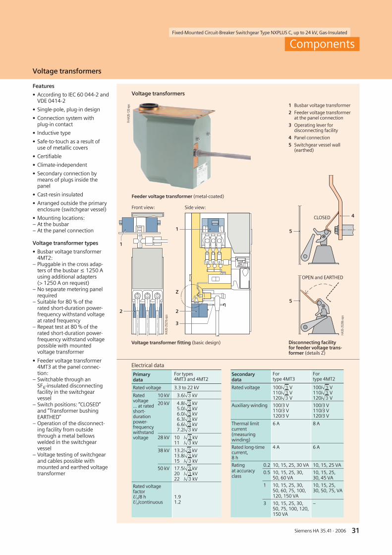
Electrical data
Primarydata
For types4MT3 and 4MT2
Rated voltage 3.3 to 22 kV
Ratedvoltage... at ratedshort-durationpower-frequencywithstandvoltage
10 kV 3.6/ 3 kV
20 kV 4.8/ 3 kV5.0/ 3 kV6.0/ 3 kV6.3/ 3 kV6.6/ 3 kV7.2/ 3 kV
28 kV 10 / 3 kV11 / 3 kV
38 kV 13.2/ 3 kV13.8/ 3 kV15 / 3 kV
50 kV 17.5/ 3 kV20 / 3 kV22 / 3 kV
Rated voltagefactorUn/8 hUn/continuous
1.91.2
Secondarydata
Fortype 4MT3
Fortype 4MT2
Rated voltage 100/ 3 V110/ 3 V120/ 3 V
100/ 3 V110/ 3 V120/ 3 V
Auxiliary winding 100/3 V110/3 V120/3 V
100/3 V110/3 V120/3 V
Thermal limitcurrent(measuringwinding)
6 A 8 A
Rated long-timecurrent,8 h
4 A 6 A
Ratingat accuracyclass
0.2 10, 15, 25, 30 VA 10, 15, 25 VA
0.5 10, 15, 25, 30,50, 60 VA
10, 15, 25,30, 45 VA
1 10, 15, 25, 30,50, 60, 75, 100,120, 150 VA
10, 15, 25,30, 50, 75, VA
3 10, 15, 25, 30,50, 75, 100, 120,150 VA
–
Components
Voltage transformers
Front view: Side view:
Voltage transformers
Feeder voltage transformer (metal-coated)
Features
• According to IEC 60 044-2 andVDE 0414-2
• Single-pole, plug-in design
• Connection system withplug-in contact
• Inductive type
• Safe-to-touch as a result ofuse of metallic covers
• Certifiable
• Climate-independent
• Secondary connection bymeans of plugs inside thepanel
• Cast-resin insulated
• Arranged outside the primaryenclosure (switchgear vessel)
• Mounting locations:– At the busbar– At the panel connection
Voltage transformer types
• Busbar voltage transformer4MT2:
– Pluggable in the cross adap-ters of the busbar ≤ 1250 Ausing additional adapters(> 1250 A on request)
– No separate metering panelrequired
– Suitable for 80 % of therated short-duration power-frequency withstand voltageat rated frequency
– Repeat test at 80 % of therated short-duration power-frequency withstand voltagepossible with mountedvoltage transformer
• Feeder voltage transformer4MT3 at the panel connec-tion:
– Switchable through anSF6-insulated disconnectingfacility in the switchgearvessel
– Switch positions: ”CLOSED”and ”Transformer bushingEARTHED”
– Operation of the disconnect-ing facility from outsidethrough a metal bellowswelded in the switchgearvessel
– Voltage testing of switchgearand cables possible withmounted and earthed voltagetransformer
Voltage transformer fitting (basic design)
CLOSED
OPEN and EARTHED
1 Busbar voltage transformer
2 Feeder voltage transformerat the panel connection
3 Operating lever fordisconnecting facility
4 Panel connection
5 Switchgear vessel wall(earthed)
Disconnecting facilityfor feeder voltage trans-former (details Z)
Fixed-Mounted Circuit-Breaker Switchgear Type NXPLUS C, up to 24 kV, Gas-Insulated
32 Siemens HA 35.41 · 2006
������� �
�� �� ��
��� ��� ������
������������
� �
������� �
�� �� ��
������������
� �
�
� �
���
�
�� �� ��
����
����
����
� � �
� �
���
����
����
����
�� �� ��
��� ��� ������ ��� ��� ���
� �� �
� �
���
������������
�� �� ��
� � �
� �
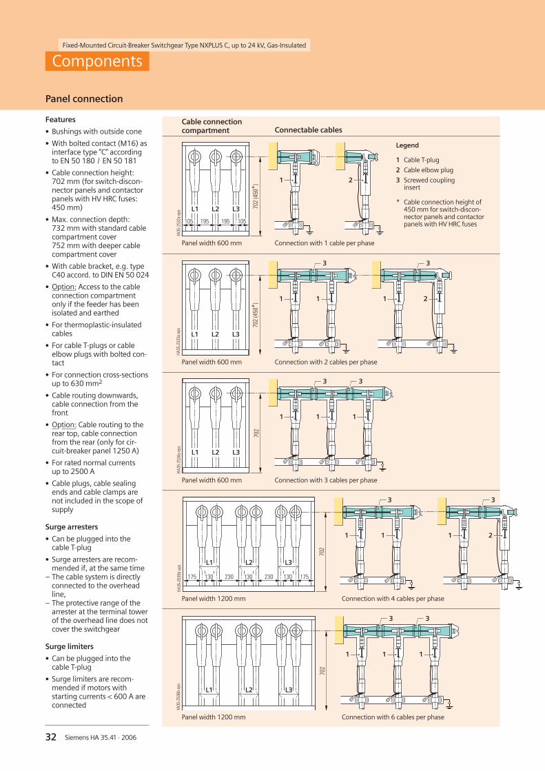
Components
Features
• Bushings with outside cone
• With bolted contact (M16) asinterface type ”C” accordingto EN 50 180 / EN 50 181
• Cable connection height:702 mm (for switch-discon-nector panels and contactorpanels with HV HRC fuses:450 mm)
• Max. connection depth:732 mm with standard cablecompartment cover752 mm with deeper cablecompartment cover
• With cable bracket, e.g. typeC40 accord. to DIN EN 50 024
• Option: Access to the cableconnection compartmentonly if the feeder has beenisolated and earthed
• For thermoplastic-insulatedcables
• For cable T-plugs or cableelbow plugs with bolted con-tact
• For connection cross-sectionsup to 630 mm2
• Cable routing downwards,cable connection from thefront
• Option: Cable routing to therear top, cable connectionfrom the rear (only for cir-cuit-breaker panel 1250 A)
• For rated normal currentsup to 2500 A
• Cable plugs, cable sealingends and cable clamps arenot included in the scope ofsupply
Surge arresters
• Can be plugged into thecable T-plug
• Surge arresters are recom-mended if, at the same time
– The cable system is directlyconnected to the overheadline,
– The protective range of thearrester at the terminal towerof the overhead line does notcover the switchgear
Surge limiters
• Can be plugged into thecable T-plug
• Surge limiters are recom-mended if motors withstarting currents < 600 A areconnected
Panel width 600 mm
Panel width 600 mm
Panel width 600 mm
Panel width 1200 mm
Panel width 1200 mm
Cable connectioncompartment
Connection with 2 cables per phase
Connection with 3 cables per phase
Connection with 4 cables per phase
Connection with 6 cables per phase
Legend
1 Cable T-plug
2 Cable elbow plug
3 Screwed couplinginsert
* Cable connection height of450 mm for switch-discon-nector panels and contactorpanels with HV HRC fuses
Connection with 1 cable per phase
Connectable cables
Panel connection

33Siemens HA 35.41 · 2006
Fixed-Mounted Circuit-Breaker Switchgear Type NXPLUS C, up to 24 kV, Gas-Insulated
Installation possibilities for cable connections and surge arresters
Numberof cablesper paneland phase
Make Core cross-section 1)
mm2
Insula-tion
Cableelbow plugs
bolted
CableT-plugs
bolted
Coupling inserts /coupling plugs
bolted
Surge arresters with coupling insertsArresters Coupling inserts
additionally additionally
• Circuit-breaker panel 630 A, 1000 A • Switch-disconnector panel 630 A • Disconnector panel 1000 A • Ring-main panel 630 A• Contactor panel • Circuit-breaker panel with cable connection from the rear top 1250 A
1 Euromold 35 to 300 EPDM – 1x(K)400 TB/G – 1x156SA-X or1x400PB-5/10-SA-X
K400RTPA–
185 to 630 EPDM – 1x(K)440 TB/G – 1x156SA-X or1x400PB-5/10-SA-X
K400RTPA–
up to 240 Silicone – 1xAGT 10(20),metal housing
– – –
up to 240 Silicone – 1xAGT L10(20),w/o metal housing
– – –
up to 300 EPDM 1x(K)400 LB/G – – – –
Südkabel (ABB) 25 to 240 Silicone – 1xSET 12 – 1xMUT 23 –
25 to 240 Silicone – 1xSET 24 – 1xMUT 23 –
300 to 500 Silicone – 1xSEHDT 13 – 1xMUT 33 1xKU 33
300 to 500 Silicone – 1xSEHDT 23 – 1xMUT 33 1xKU 33
nkt cables 25 to 300 Silicone – 1xCB/AB 24 630 – 1xCSA/ASA –
400 to 630 Silicone – 1xCB 36/630 – 1xCSA 12/24-x –
Tyco ElectronicsRaychem
25 to 300 Silicone – 1xRSTI-L56xx – 1xRSTI-CC-L56SAxx05/10 –
400 to 630 Silicone – 1xRSTI-xxLxx – 1xRSTI-L56SAxx05/10 1xRSTI-66CP-M16
2 2) Euromold 35 to 300 EPDM – 2x(K)400 TB/G 1x(K)400CP – –
up to 300 EPDM 1x(K)400 LB/G 1x(K)400 TB/G 1x(K)400CP-LB – –
185 to 630 EPDM – 2x(K)440 TB/G 1x(K)440CP – –
up to 240 Silicone – 2xAGT 10(20),metal housing
1xCP-AGT(L) – –
up to 240 Silicone – 2xAGT 10(20),w/o metal housing
1xCP-AGT(L) – –
Südkabel (ABB) 25 to 240 Silicone – 2xSET 12 1xKU23.2 1xMUT 23 –
25 to 240 Silicone – 2xSET 24 1xKU23.2 1xMUT 23 –
300 to 500 Silicone – 2xSEHDT 13 1xKU23 – –
300 to 500 Silicone – 2xSEHDT 23 1xKU23 – –
nkt cables 25 to 300 Silicone – 2xCB/AB 24 630 1xCP630C/A 1xCSA/ASA –
25 to 300 Silicone – 1xCB/AB 24 630+1xCC/AC 24 630
– 1xCSA/ASA –
400 to 630 Silicone – 2xCB 36/630 1xCP630C 1xCSA 12/24x –
400 to 630 Silicone – 1xCB 36/630+1xCC 36/630
– 1xCSA 12/24x –
Tyco ElectronicsRaychem
25 to 300 Silicone – 1xRSTI-L56xx 1xRSTI-CC-L56xx 1xRSTI-CC-L56SAxx05/10 –
400 to 630 Silicone – 2xRSTI-xxLxx 1xRSTI-66CP-M16 1xRSTI-L56SAxx05/10 1xRSTI-66CP-M16
• Circuit-breaker panel 1250 A 3) • Disconnector panel 1250 A 3)
1 Same combination options as in the table above
2 Euromold 35 to 300 EPDM – 2x(K)400 TB/G 1x(K)400CP 1x156SA-X –
185 to 630 EPDM – 2x(K)440 TB/G 1x(K)440CP 1x400PB-5/10-SA-X –
Otherwise same combination options as in the table above
3 Euromold 35 to 300 4) EPDM – 3x(K)400 TB/G 2x(K)440CP – –
Südkabel (ABB) 25 to 240 Silicone – 3xSET 12 2xKU23.2 1xMUT 23 –
25 to 240 Silicone – 3xSET 24 2xKU23.2 1xMUT 23 –
nkt cables 25 to 300 Silicone – 1xCB/AB 24/630+2xCC/AC 24/630
– 1xCSA/ASA –
400 to 630 Silicone – 1xCB 36/630+2xCC 36/630
– 1xCSA/ASA –
Tyco ElectronicsRaychem
25 to 300 Silicone – 1xRSTI-L56xx 2xRSTI-CC-L56xx 1xRSTI-CC-L56SAxx05/10 –
400 to 630 Silicone – 3xRSTI-xxLxx 2xRSTI-66CP-M16 1xRSTI-L56SAxx05/10 1xRSTI-66CP-M16
1) Observe the actual short-circuit and current carrying capacity of the cables and sealing ends.
2) The use of arresters is not possible for cable connection panels 1250 A with cable connection from the rear/top.
3) For the 1250 A version only sealing ends with silver-plated or nickel-plated cable lugs are permissible.
4) Only possible with deeper cable compartment cover.
Components
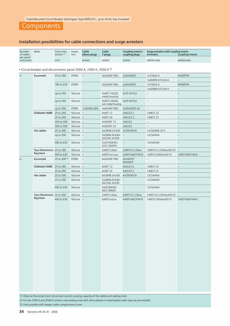
34 Siemens HA 35.41 · 2006
Fixed-Mounted Circuit-Breaker Switchgear Type NXPLUS C, up to 24 kV, Gas-Insulated
Installation possibilities for cable connections and surge arresters
1) Observe the actual short-circuit and current carrying capacity of the cables and sealing ends.
2) For the 2300 A and 2500 A version only sealing ends with silver-plated or nickel-plated cable lugs are permissible.
3) Only possible with deeper cable compartment cover.
Numberof cablesper paneland phase
Make Core cross-section 1)
mm2
Insula-tion
Cableelbow plugs
bolted
CableT-plugs
bolted
Coupling inserts /coupling plugs
bolted
Surge arresters with coupling insertsArresters Coupling inserts
additionally additionally
• Circuit-breaker and disconnector panel 2000 A, 2300 A, 2500 A 2)
4 Euromold 35 to 300 EPDM – 4x(K)400 TB/G 2x(K)400CP 1x156SA-X K400RTPA
1x400PB-5/10-SA-X –
185 to 630 EPDM – 4x(K)440 TB/G 2x(K)400CP 1x156SA-X K400RTPA
– 1x400PB-5/10-SA-X –
up to 240 Silicone – 4xAGT 10(20),metal housing
2xCP-AGT(L) – –
up to 240 Silicone – 4xAGT L10(20),w/o metal housing
2xCP-AGT(L) – –
up to 300 EPDM 1x(K)400 LB/G 4x(K)400 TB/G 2x(K)400CP-LB – –
Südkabel (ABB) 25 to 240 Silicone – 4xSET 12 2xKU23.2 1xMUT 23 –
25 to 240 Silicone – 4xSET 24 2xKU23.2 1xMUT 23 –
300 to 500 Silicone – 4xSEHDT 13 2xKU23 – –
300 to 500 Silicone – 4xSEHDT 23 2xKU23 – –
nkt cables 25 to 300 Silicone – 4xCB/AB 24 630 2xCP630C/A 1xCSA/ASA 24-5 –
up to 300 Silicone – 2xCB/AB 24 630+2xCC/AC 24 630
– 1xCSA/ASA –
400 to 630 Silicone – 2xCB 36/630+2xCC 36/630
– 1xCSA/ASA –
Tyco ElectronicsRaychem
25 to 300 Silicone – 2xRSTI-L56xx 2xRSTI-CC-L56xx 1xRSTI-CC-L56SAxx05/10 –
400 to 630 Silicone – 4xRSTI-xx-Lxx+ 2xRSTI-66CP-M16 1xRSTI-L56SAxx05/10 1xRSTI-66CP-M16
6 Euromold 35 to 300 3) EPDM – 6x(K)400 TB/G (K)440CP/(K)400CP
– –
Südkabel (ABB) 25 to 240 Silicone – 6xSET 12 4xKU23.2 1xMUT 23 –
25 to 240 Silicone – 6xSET 24 4xKU23.2 1xMUT 23 –
nkt cables 25 to 300 Silicone – 6xCB/AB 24 630 4xCP630C/A 1xCSA/ASA –
25 to 300 Silicone – 2xCB/AB 24 630+4xCC/AC 24 630
– 1xCSA/ASA –
400 to 630 Silicone – 2xCB 36/630+4xCC 36/630
– 1xCSA/ASA –
Tyco ElectronicsRaychem
25 to 300 Silicone – 2xRSTI-L56xx 4xRSTI-CC-L56xx 1xRSTI-CC-L56SAxx05/10 –
400 to 630 Silicone – 6xRSTI-xxLxx 4xRSTI-66CP-M16 1xRSTI-L56SAxx05/10 1xRSTI-66CP-M16
Components

Fixed-Mounted Circuit-Breaker Switchgear Type NXPLUS C, up to 24 kV, Gas-Insulated
35Siemens HA 35.41 · 2006
Panel connection (cable sealing ends available on the market)
1) T = Cable T-plug, W = Cable elbow plug
Cable type Cable sealing end (further types on request) Comment
Make Type Design Cross-sectionT/W 1) mm2
Thermoplastic-insulated cables 12 kV according to IEC 60502-2 and VDE 0276-620
1-core cable,PE and XLPE-insulated
N2YSY (Cu) andN2XSY (Cu)
or
NA2YSY (AI) andNA2XSY (AI)
Euromold 400 TB/G T 35–300 EPDM (conductive)
400 LB/G W 35–300 EPDM (conductive)
440 TB/G T 185–630 EPDM (conductive)
AGT 10 T up to 240 Silicone with metal housing
AGTL 10 T up to 240 Silicone (conductive)
nkt cables CB 24-630 T 25–300 Silicone (conductive), option: with metal housing
Südkabel (ABB) SET 12 T 25–240 Silicone (conductive), option: with metal housing
SEHDT 13 T 300–500 Silicone (conductive), option: with metal housing
Tyco ElectronicsRaychem
RSTI L56.. T 25–300 Silicone (conductive), with capacitive measuring point
RSTI-xxLxx.. T 400–630 Silicone (conductive), with capacitive measuring point
Thermoplastic-insulated cables 15/17.5/24 kV according to IEC 60502-2 and VDE 0276-620
1-core cable,PE and XLPE-insulated
N2YSY (Cu) andN2XSY (Cu)
or
NA2YSY (AI) andNA2XSY (AI)
Euromold K400 TB/G T 35–300 EPDM (conductive)
K400 LB/G W 35–300 EPDM (conductive)
K440 TB/G T 185–630 EPDM (conductive)
AGT 20 T up to 240 Silicone with metal housing, multi-range design
AGTL 20 T up to 240 Silicone (conductive)
nkt cables CB 24-630 T 25–300 Silicone (conductive), option: with metal housing
Südkabel (ABB) SET 24 T 25–240 Silicone (conductive), option: with metal housing
SEHDT 23 T 300–500 Silicone (conductive), option: with metal housing
for single-core cables RSTI L56.. T 25–300 Silicone (conductive), with capacitive measuring point
RSTI-xxLxx.. T 400–630 Silicone (conductive), with capacitive measuring point
Components
TycoElectronicsRaychem

Fixed-Mounted Circuit-Breaker Switchgear Type NXPLUS C, up to 24 kV, Gas-Insulated
36 Siemens HA 35.41 · 2006
Components
Indicating and measuring equipment
Voltage detection systemsacc. to IEC 61243-5 orVDE 0682-415
• To verify safe isolation fromsupply
• Detection systems– LRM system with plug-in
indicator– LRM system with integrated
indicator type VOIS+– LRM system with integrated
indicator, with integratedrepeat test of the interface,with integrated function testtype CAPDIS-S1+
– LRM system with integratedindicator, with integratedrepeat test of the interface,with integrated function test,with integrated signallingrelay type CAPDIS-S2+
LRM system
• Verification of safe isolationfrom supply phase by phaseby insertion in each socketpair
• Indicator suitable forcontinuous operation
• Safe-to-touch
• Routine-tested
• Measuring system and volt-age indicator can be tested
• Voltage indicator flasheswhen high voltage is present
VOIS+
• Integrated display, withoutauxiliary power
• With indication “A1” to “A3”,(see legend)
• Maintenance-free
• With integrated 3-phase testsocket for phase comparison(also suitable for plug-in volt-age indicator)
• Degree of protection IP 67,temperature range -25 °C to+55 °C
CAPDIS-Sx+
Common features
• Maintenance-free
• Integrated display, withoutauxiliary power
• Integrated repeat test of theinterfaces (self-testing)
• With integrated function test(without auxiliary power) bypressing the “Device-Func-tion-Test” pushbutton
plugged-inLRMsystem
Voltage indicationwith capacitive voltage divider (principle)
– C1 Capacity integrated into bushing
– C2 Capacity of the connection leads andof the voltage indicator to earth
R-HA
40-1
03ep
sR-
HA40
-102
aep
s
Plug-in voltage indicatorper phase atthe panel front
Integrated voltage detection systemCAPDIS-S1+, -S2+
�����������
���
��� ��� ��
����
�
mountedCAPDIS
Voltage indicators and detection systems
R-HA
40-1
04ep
s
Integrated voltage indicatorVOIS+
A0
A1
A2
A3
A4
A5
A6
A0 CAPDIS-S2+: Operating voltagenot present
A1 Operating voltage present
A2 – Operating voltage not present– For CAPDIS-S2+:
Auxiliary power not present
A3 Failure in phase L1, operating voltageat L2 and L3 (for CAPDIS-Sx+ alsoindication: Earth fault)
A4 Voltage (not operating voltage)present
A5 Indication “Device-Function-Test”passed
A6 Indication “ERROR”, e.g. in case ofmissing auxiliary voltage(see: “error indication M4“)
Symbols shown
VOIS+ CAPDIS-S1+ CAPDIS-S2+
���� �� ���� ��
�����
���� ��
������������
• With integrated 3-phase testsocket for phase comparison(also suitable for plug-involtage indicator)
• Degree of protection IP 54,temperature range –25 °C to+55 °C
• With circuit capacity
Features of CAPDIS-S1+
• Without auxiliary power
• With indication “A1” to “A5”(see legend)
• Without ready-for-servicemonitoring
• Without signalling relay (thuswithout auxiliary contacts)
• With integrated signalling re-lay for signalling “M1” to “M4”(auxiliary power required):
– “M1”: Operating voltagepresent at phases L1, L2, L3
– “M2”: Voltage not present atL1, L2 and L3 (= active zeroindication)
– “M3”: Earth fault or voltagefailure, e.g. in one phase
– “M4”: External auxiliarypower missing (operatingvoltage present or not)
Features of CAPDIS-S2+
• With indication “A0” to “A6”(see legend)
• Only by pressing the“Device-Function-Test”pushbutton: “ERROR” indica-tion (A6), e.g. in case ofmissing auxiliary voltage
• With ready-for-servicemonitoring (external auxiliarypower required)
• Separate circuit capacity
ULE = UN / 3 during rated operationin the three-phase system
U2 = UA= Voltage at the capacitive interfaceof the switchgear or at the voltage indicator
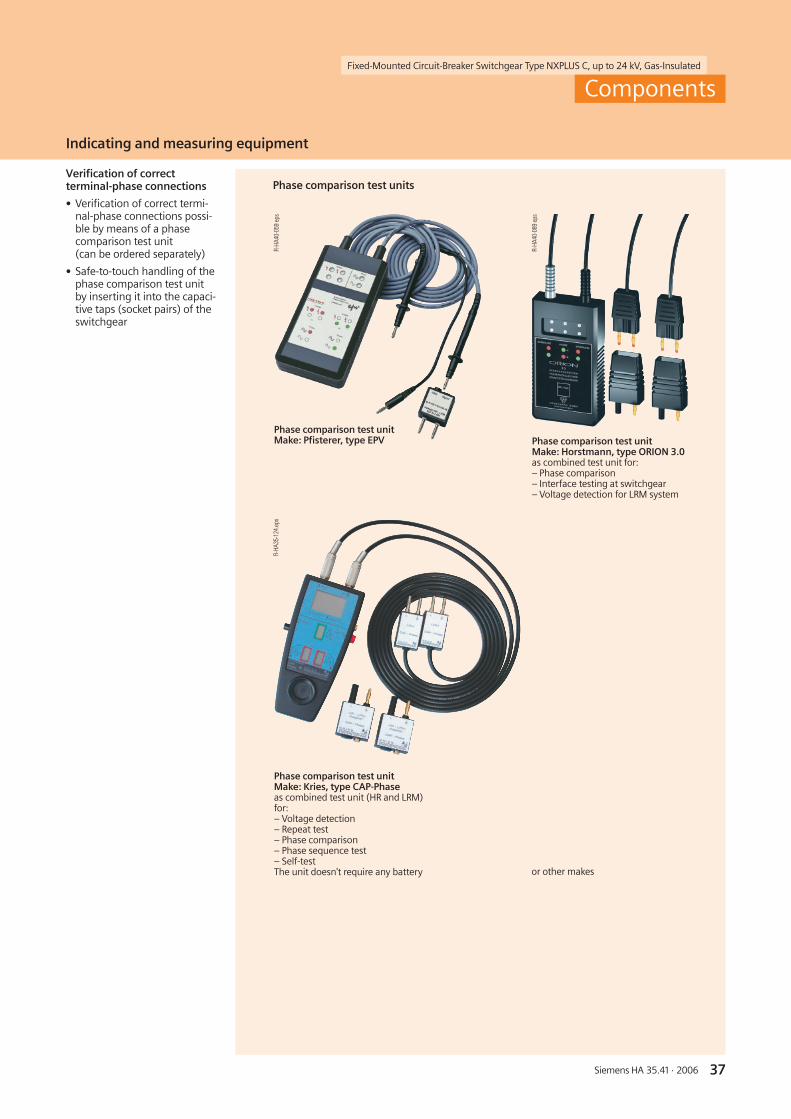
Fixed-Mounted Circuit-Breaker Switchgear Type NXPLUS C, up to 24 kV, Gas-Insulated
37Siemens HA 35.41 · 2006
Verification of correctterminal-phase connections
• Verification of correct termi-nal-phase connections possi-ble by means of a phasecomparison test unit(can be ordered separately)
• Safe-to-touch handling of thephase comparison test unitby inserting it into the capaci-tive taps (socket pairs) of theswitchgear
Phase comparison test units
R-HA
40-0
59ep
s
Phase comparison test unitMake: Pfisterer, type EPV
R-HA
40-0
89ep
s
Indicating and measuring equipment
Components
Phase comparison test unitMake: Horstmann, type ORION 3.0as combined test unit for:– Phase comparison– Interface testing at switchgear– Voltage detection for LRM system
Phase comparison test unitMake: Kries, type CAP-Phaseas combined test unit (HR and LRM)for:– Voltage detection– Repeat test– Phase comparison– Phase sequence test– Self-testThe unit doesn't require any battery
R-HA
35-1
24.e
ps
or other makes

Fixed-Mounted Circuit-Breaker Switchgear Type NXPLUS C, up to 24 kV, Gas-Insulated
38 Siemens HA 35.41 · 2006
�
��
�
�����������
Gas monitoring
R-HA
35-1
05ep
s
1
R-HA
35-1
12a
eps
Components
Indicating and measuring equipment
Ready-for-service indicator
Features
• Self-monitoring; easy to read
• Independent of temperatureand pressure variations
• Independent of site altitude
• Only responds to changes ingas density
• Option: Alarm switch ”1NO +1NC” for remote electrical in-dication
Mode of operation
For the ready-for-service indi-cator, a gas-tight measurementbox is installed inside theswitchgear vessel.
A coupling magnet, which isfitted to the bottom end of themeasurement box, transmits itsposition to an outside armaturethrough the non-magnetizablestainless-steel switchgearvessel. This armature movesthe ready-for-service indicatorof the switchgear.
While changes in the gas densi-ty during the loss of gas, whichare decisive for the insulatingcapacity, are displayed, tempe-rature-dependent changes inthe gas pressure are not. Thegas in the measurement boxhas the same temperature asthat in the switchgear.
The temperature effect is com-pensated via the same pressurechange in both gas volumes.
Low-voltage compartment
• Accommodates equipmentfor protection, control,measuring and metering
• Separated from the high-voltage part of the panel,safe-to-touch
• Low-voltage compartmentcan be removed, bus wiresand control cables areplugged in
• Option: High low-voltagecompartment (1161 mminstead of 761 mm) possible
Low-voltage compartment
Control board (detail)with red/green ready-for-serviceindicator
Low-voltage compartment withmultifunction protection relay SIPROTEC 4 7SJ61(example)
Descriptionof the SIPROTEC 4 multifunction protection relays,see page 39.
1 Ready-for-service indicator
2 Measurement box
3 Magnetic coupling
4 Red indication:not ready for service
5 Green indication:ready for service
Principle of operationof gas monitoringwith ready-for-service indicator
Stainless-steel vesselfilled with SF6-gas,gauge pressure50 kPa at 20 °C
Ready-for-serviceindicator
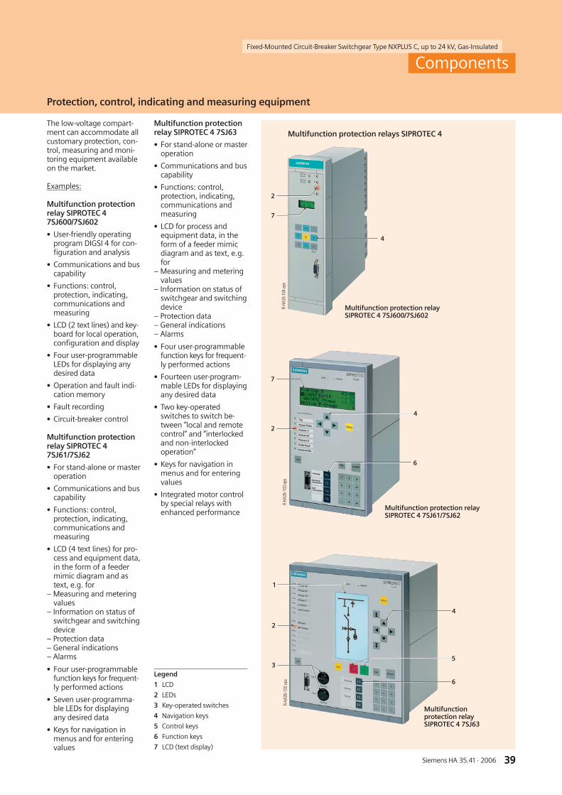
39Siemens HA 35.41 · 2006
Fixed-Mounted Circuit-Breaker Switchgear Type NXPLUS C, up to 24 kV, Gas-Insulated
39
4
5
6
2
3
R-HA
35-1
02ep
sR-
HA35
-104
eps
R-HA
35-1
03ep
s
1
7
2
6
4
4
2
7
Components
Protection, control, indicating and measuring equipment
Multifunction protectionrelay SIPROTEC 4 7SJ63
• For stand-alone or masteroperation
• Communications and buscapability
• Functions: control,protection, indicating,communications andmeasuring
• LCD for process andequipment data, in theform of a feeder mimicdiagram and as text, e.g.for
– Measuring and meteringvalues
– Information on status ofswitchgear and switchingdevice
– Protection data– General indications– Alarms
• Four user-programmablefunction keys for frequent-ly performed actions
• Fourteen user-program-mable LEDs for displayingany desired data
• Two key-operatedswitches to switch be-tween ”local and remotecontrol” and ”interlockedand non-interlockedoperation”
• Keys for navigation inmenus and for enteringvalues
• Integrated motor controlby special relays withenhanced performance
The low-voltage compart-ment can accommodate allcustomary protection, con-trol, measuring and moni-toring equipment availableon the market.
Examples:
Multifunction protectionrelay SIPROTEC 47SJ600/7SJ602
• User-friendly operatingprogram DIGSI 4 for con-figuration and analysis
• Communications and buscapability
• Functions: control,protection, indicating,communications andmeasuring
• LCD (2 text lines) and key-board for local operation,configuration and display
• Four user-programmableLEDs for displaying anydesired data
• Operation and fault indi-cation memory
• Fault recording
• Circuit-breaker control
Multifunction protectionrelay SIPROTEC 47SJ61/7SJ62
• For stand-alone or masteroperation
• Communications and buscapability
• Functions: control,protection, indicating,communications andmeasuring
• LCD (4 text lines) for pro-cess and equipment data,in the form of a feedermimic diagram and astext, e.g. for
– Measuring and meteringvalues
– Information on status ofswitchgear and switchingdevice
– Protection data– General indications– Alarms
• Four user-programmablefunction keys for frequent-ly performed actions
• Seven user-programma-ble LEDs for displayingany desired data
• Keys for navigation inmenus and for enteringvalues
Legend
1 LCD
2 LEDs
3 Key-operated switches
4 Navigation keys
5 Control keys
6 Function keys
7 LCD (text display)
Multifunctionprotection relaySIPROTEC 4 7SJ63
Multifunction protection relaySIPROTEC 4 7SJ61/7SJ62
Multifunction protection relaySIPROTEC 4 7SJ600/7SJ602
Multifunction protection relays SIPROTEC 4
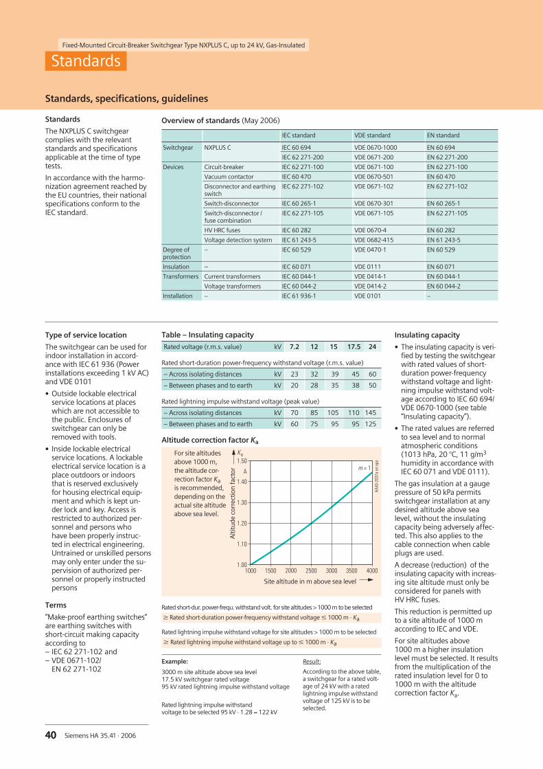
40 Siemens HA 35.41 · 2006
Fixed-Mounted Circuit-Breaker Switchgear Type NXPLUS C, up to 24 kV, Gas-Insulated
40
For site altitudesabove 1000 m,the altitude cor-rection factor Kais recommended,depending on theactual site altitudeabove sea level.
����������������
����
����
����
����
�������� ���� ����
�
����
� �
��
����
����
�����
�
Result:
According to the above table,a switchgear for a rated volt-age of 24 kV with a ratedlightning impulse withstandvoltage of 125 kV is to beselected.
Overview of standards (May 2006)
IEC standard VDE standard EN standard
Switchgear NXPLUS C IEC 60 694 VDE 0670-1000 EN 60 694
IEC 62 271-200 VDE 0671-200 EN 62 271-200
Devices Circuit-breaker IEC 62 271-100 VDE 0671-100 EN 62 271-100
Vacuum contactor IEC 60 470 VDE 0670-501 EN 60 470
Disconnector and earthingswitch
IEC 62 271-102 VDE 0671-102 EN 62 271-102
Switch-disconnector IEC 60 265-1 VDE 0670-301 EN 60 265-1
Switch-disconnector /fuse combination
IEC 62 271-105 VDE 0671-105 EN 62 271-105
HV HRC fuses IEC 60 282 VDE 0670-4 EN 60 282
Voltage detection system IEC 61 243-5 VDE 0682-415 EN 61 243-5
Degree ofprotection
– IEC 60 529 VDE 0470-1 EN 60 529
Insulation – IEC 60 071 VDE 0111 EN 60 071
Transformers Current transformers IEC 60 044-1 VDE 0414-1 EN 60 044-1
Voltage transformers IEC 60 044-2 VDE 0414-2 EN 60 044-2
Installation – IEC 61 936-1 VDE 0101 –
Standards, specifications, guidelines
Standards
The NXPLUS C switchgearcomplies with the relevantstandards and specificationsapplicable at the time of typetests.
In accordance with the harmo-nization agreement reached bythe EU countries, their nationalspecifications conform to theIEC standard.
Alti
tude
corr
ectio
nfa
ctor
Site altitude in m above sea level
Type of service location
The switchgear can be used forindoor installation in accord-ance with IEC 61 936 (Powerinstallations exceeding 1 kV AC)and VDE 0101
• Outside lockable electricalservice locations at placeswhich are not accessible tothe public. Enclosures ofswitchgear can only beremoved with tools.
• Inside lockable electricalservice locations. A lockableelectrical service location is aplace outdoors or indoorsthat is reserved exclusivelyfor housing electrical equip-ment and which is kept un-der lock and key. Access isrestricted to authorized per-sonnel and persons whohave been properly instruc-ted in electrical engineering.Untrained or unskilled personsmay only enter under the su-pervision of authorized per-sonnel or properly instructedpersons
Terms
”Make-proof earthing switches”are earthing switches withshort-circuit making capacityaccording to– IEC 62 271-102 and– VDE 0671-102/
EN 62 271-102Example:
3000 m site altitude above sea level17.5 kV switchgear rated voltage95 kV rated lightning impulse withstand voltage
Rated lightning impulse withstandvoltage to be selected 95 kV · 1.28 = 122 kV
Standards
Altitude correction factor Ka
Table – Insulating capacity
Rated voltage (r.m.s. value) kV 7.2 12 15 17.5 24
Rated short-duration power-frequency withstand voltage (r.m.s. value)
– Across isolating distances kV 23 32 39 45 60
– Between phases and to earth kV 20 28 35 38 50
Rated lightning impulse withstand voltage (peak value)
– Across isolating distances kV 70 85 105 110 145
– Between phases and to earth kV 60 75 95 95 125
Rated short-dur. power-frequ. withstand volt. for site altitudes > 1000 m to be selected
W Rated short-duration power-frequency withstand voltage w 1000 m · Ka
Rated lightning impulse withstand voltage for site altitudes > 1000 m to be selected
W Rated lightning impulse withstand voltage up to w 1000 m · Ka
Insulating capacity
• The insulating capacity is veri-fied by testing the switchgearwith rated values of short-duration power-frequencywithstand voltage and light-ning impulse withstand volt-age according to IEC 60 694/VDE 0670-1000 (see table“Insulating capacity”).
• The rated values are referredto sea level and to normalatmospheric conditions(1013 hPa, 20 °C, 11 g/m3
humidity in accordance withIEC 60 071 and VDE 0111).
The gas insulation at a gaugepressure of 50 kPa permitsswitchgear installation at anydesired altitude above sealevel, without the insulatingcapacity being adversely affec-ted. This also applies to thecable connection when cableplugs are used.
A decrease (reduction) of theinsulating capacity with increas-ing site altitude must only beconsidered for panels withHV HRC fuses.
This reduction is permitted upto a site altitude of 1000 maccording to IEC and VDE.
For site altitudes above1000 m a higher insulationlevel must be selected. It resultsfrom the multiplication of therated insulation level for 0 to1000 m with the altitudecorrection factor Ka.
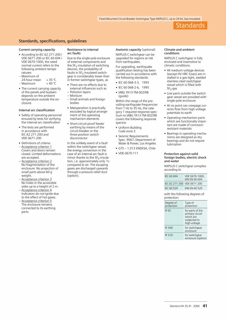
Fixed-Mounted Circuit-Breaker Switchgear Type NXPLUS C, up to 24 kV, Gas-Insulated
41Siemens HA 35.41 · 2006 41
Climate and ambientconditions
NXPLUS C switchgear is fullyenclosed and insensitive toclimatic conditions.
• All medium-voltage devices(except HV HRC fuses) are in-stalled in a gas-tight, weldedstainless steel switchgearvessel which is filled withSF6-gas
• Live parts outside the switch-gear vessel are provided withsingle-pole enclosure
• At no point can creepage cur-rents flow from high-voltagepotentials to earth
• Operating mechanism partswhich are functionally impor-tant are made of corrosion-resistant materials
• Bearings in operating mecha-nisms are designed as drybearings and do not requirelubrication
Protection against solidforeign bodies, electric shockand water
NXPLUS C switchgear compliesaccording to
with the following degrees ofprotection:
Resistance to internalarc faults
Due to the single-pole enclosureof external components andthe SF6-insulation of switchingdevices, the probability offaults in SF6-insulated switch-gear is considerably lower thanin former switchgear types, as
• There are no effects due toexternal influences such as
– Pollution layers– Moisture– Small animals and foreign
bodies
• Maloperation is practicallyexcluded by logical arrange-ment of the operatingmechanism elements
• Short-circuit-proof feederearthing by means of thecircuit-breaker or thethree-position switch-disconnector
In the unlikely event of a faultwithin the switchgear vessel,the energy conversion in thecase of an internal arc fault isminor thanks to the SF6-insula-tion, i.e. approximately only 1/3compared to air. The escapinggases are discharged upwardsthrough a pressure relief duct(option).
Current carrying capacity
• According to IEC 62 271-200 /VDE 0671-200 or IEC 60 694 /VDE 0670-1000, the ratednormal current refers to thefollowing ambient tempe-ratures:
– Maximum of24-hour mean + 35 °C
– Maximum + 40 °C
• The current carrying capacityof the panels and busbarsdepends on the ambienttemperature outside the en-closure.
Internal arc classification
• Safety of operating personnelensured by tests for verifyingthe internal arc classification
• The tests are performedin accordance withIEC 62 271-200 andVDE 0671-200
• Definitions of criteria:– Acceptance criterion 1
Covers and doors remainclosed. Limited deformationsare accepted.
– Acceptance criterion 2No fragmentation of theenclosure. No projection ofsmall parts above 60 gweight.
– Acceptance criterion 3No holes in the accessiblesides up to a height of 2 m.
– Acceptance criterion 4Indicators do not ignite dueto the effect of hot gases.
– Acceptance criterion 5The enclosure remainsconnected to its earthingparts.
Aseismic capacity (optional)
NXPLUS C switchgear can beupgraded for regions at riskfrom earthquakes.
For upgrading, earthquakequalification testing has beencarried out in accordance withthe following standards:
• IEC 60 068-3-3, 1993
• IEC 60 068-2-6, 1995
• IABG TA13-TM-002/98(guide)
Within the range of the pre-vailing earthquake frequenciesfrom 1 Hz to 35 Hz, the cate-gory 1 required response spec-trum to IABG TA13-TM-002/98covers the following responsespectra:
• Uniform BuildingCode zone 3
• Seismic RequirementsSpec. 9067; Department ofWater & Power, Los Angeles
• GTS – 1.013 ENDESA, Chile
• VDE 0670-111
Standards
Standards, specifications, guidelines
IEC 60 694 VDE 0670-1000,DIN EN 60 694
IEC 62 271-200 VDE 0671-200
IEC 60 529 DIN EN 60 529
Degree ofprotection
Type ofprotection
IP 65 for parts of theprimary circuitwhich aresubjected tohigh-voltage
IP 3XD for switchgearenclosure
IP 31D for switchgearenclosure (option)

42 Siemens HA 35.41 · 2006
Fixed-Mounted Circuit-Breaker Switchgear Type NXPLUS C, up to 24 kV, Gas-Insulated
Responsible for
Technical contents:Oliver NöldnerSiemens AG, Dept. PTD M 2 PPMErlangen
General editing:Gabriele PollokSiemens AG, Dept. PTD CC MErlangen


Siemens AGPower Transmission and DistributionMedium Voltage DivisionPostfach 32 40
91050 ErlangenGermany
www.siemens.com/medium-voltage-switchgear
If you have any questions aboutPower Transmission and Distribution,our Customer Support Centeris available around the clock
Tel.: +49 180 / 524 70 00Fax: +49 180 / 524 24 71
(Subject to charges, e.g.: 12 ct/min.)
E-Mail: [email protected]/energy-support
Printed in GermanyKG 06.06 0.0 40 En 101879 6101/C6080
If not stated otherwise on the individual pages of thiscatalog, we reserve the right to include modifications,especially regarding the stated values, dimensions andweights.
Drawings are not binding.
All product designations used are trademarksor product names of Siemens AGor other suppliers.
If not stated otherwise, all dimensions in thiscatalog are given in mm.
The information in this document contains generaldescriptions of the technical options available,which do not always have to be present in individualcases.The required features should therefore be specified ineach individual case at the time of closing the contract.
Recommended