Finite Element Modeling Of Reinforced Concrete
Columns Strengthened Externally With
CFRP Sheets
الخارج بألواح الفايبر نمذجة االعمدة الخرسانية المقواة من الكربونية باستخدام العناصر المحددة
Ahmed Jehad Ayyad
Supervised by
Dr. Mohammed Arafa
Associate prof. of Civil Engineering
Dr. Mamoun Alqedra
Associate prof. of Civil Engineering
A thesis submitted in partial fulfillment
of the requirements for the degree of
Master of Science in Civil Engineering
October /2016
زةــغ –ةــالميــــــت اإلســـــــــامعـالج
والدراسبث العليبشئىن البحث العلمي
الهنــــــــــدســــــــت ة ــــــــــــــــــــليـك
هندســــــــت مدنيــــــــت ر ـــــــمبجستي
The Islamic University–Gaza
Research and Postgraduate Affairs
Faculty of Engineering
Master of Civil Engineering

I
إقــــــــــــــرار
:أنا الموقع أدناه مقدم الرسالة التي تحمل العنوان
Finite Element Modeling Of Reinforced Concrete
Columns Strengthened Externally With
CFRP Sheets
نمذجة االعمدة الخرسانية المقواة من الخارج بألواح الفايبر الكربونية باستخدام العناصر المحددة
الة ككل أو أي أقر بأن ما اشتملت عليو ىذه الرسالة إنما ىو نتاج جيدي الخاص، باستثناء ما تمت اإلشارة إليو حيثما ورد، وأن ىذه الرس
.لنيل درجة أو لقق علمم أو بحثم لدد أي ممسسة تتليمية أو بحثية أخرد االخرين جزء منيا لم يقدم من قبل
1 Declaration
I understand the nature of plagiarism, and I am aware of the University’s policy on this.
The work provided in this thesis, unless otherwise referenced, is the researcher's own work, and
has not been submitted by others elsewhere for any other degree or qualification.
:اسم الطالق :Student's name احمد جهاد عياد
:التوقيع
Signature:
:التاريخ 16/10/2016 Date:


II
2 Abstract
Rehabilitation of old buildings is more economical than rebuilding them. That`s why the
behavior of strengthening techniques should be understood to make the best decision for
rehabilitation in order to save time and cost. The behavior of reinforced concrete column
strengthened externally with carbon fiber reinforced Polymers (CFRP) is highly affected by the
way in which these composites are applied to the column.
This study presents a simple finite element model (FE) able to estimate the load-carrying
capacity and ductility of reinforced concrete (RC) square columns strengthened with externally
bonded fiber reinforced polymer (FRP) plates / sheets.
The finite element model of reinforced concrete columns was developed for columns externally
strengthened with carbon fiber reinforced polymers (CFRP) using the commercial Finite Element
Modeling software ANSYS, in order to investigate the behavior of these columns.
The column which size was 250×250×500 mm is modeled and analyzed using a non-linear finite
element method. Two parameters of wrap thickness and fiber orientation were considered. The
finite element analysis results were in good agreement with experimental data presented by other
researchers.
The analysis results demonstrated significant enhancement in the compressive strength and
ductility of the FRP-wrapped rectangular RC columns compared to unstrengthened RC columns.
It was observed that the behavior of the columns was greatly affected by the analysis parameters.
The gain in axial compressive strength was observed to be the highest in the columns wrapped
with the hoop orientation; but the highest axial strain and ductility were observed in the columns
wrapped with the fiber orientation of ±45° with respect to the horizontal.

III
الولخص 3
قشاس أفضلالحخار األبيتباءها لهزا السبب يبغي فهن طشق دعن إعادةاقخصادا هي أمثشحأهيل الوباي القذيوت هى إعادة
.إلعادة حأهل حلل الوباي و رلل لخىفيش الىقج و الخنلفت
فيها وضعسيقت الخي يخن الفايبش النشبىيت حخأثش بصىسة مبيشة بالظ ألىاذالوذعوت هي الخاسج الخشاسايت األعوذةسلىك إى
.الفايبش ألىاذ
الوشبعت الوذعوت هي الخشسايت األعوذةو هشوت حسولبسيظ بطشيقت العاصش الوسذدة لخسذيذ قىة لوىرجو هز الذساست
.الخاسج بألىاذ الفايبش النشبىيت
، رلل هي 14 اإلصذاس ANSYSبشاهح خذامباسجالخشسايت الوذعن بألىاذ الفايبش النشبىيت األعوذةو حن حطىيش وىرج
. األعوذةاخل دساست سلىك حلل
هليوخش ص و قذ اخز بعيي االعخباس 500×250×250العوىد الخشساي الوسخخذم في وىرج العاصش الوسذدة هي أبعاد
.الفايبش النشبىيت ألىاذالوعياساى سوامت و احدا
خائح حسليل الوىرج دعن مبيش في قىة الخسول و أوضسجوقذ . وقذ خاء هزا الخسليل هخىافقا هع البيااث الوقذهت هي البازثيي
.الغيش هذعوت باألعوذةالوذعوت بالفاييبش هقاست األعوذةهشوت
أى قىة حسول األعوذة الوغطاة بألىاذ ، موا يخأثش بشنل واضر بوعاييش الخسليل األعوذةسلىك حلل إىوقذ ماى هي الولسىظ
. 45 بضاويت الخفاف باأللىاذالوغطاة األعوذةمىى األمثش بيوا حضداد الوشوت أمثش في ثالفايبش بطشيقت دائشيت

IV
4 Dedication
To my father
To my mother
To my sisters
To my wife ,
To my friends,
For their endless support

V
5 Acknowledgments
I thank almighty Allah for giving me patience, strength, and determination to accomplish this
work.
I also would like to express my sincere appreciation to my supervisors, Dr. Mohammed Arafa
and Dr. Mamoun AlQedra for their guidance and strong support throughout the duration of this
thesis.
Deep thanks and gratitude are due to my father, Mr. Jehad Ayyad and my mother Asmaa abu
baker for their infinite support and encouragement.
I would like to express my thanks to my wife Dr.Israa batta for her patience and support
during the time in which this work was done.
I also thank my sisters Huda , Hadeel and Tamam, and my friends for their encouragement.

VI
6 List of Contents
1 Declaration ............................................................................................................................... I
2 Abstract ................................................................................................................................... II
III ...........................................................................................................................الملخص 3
4 Dedication ............................................................................................................................. IV
5 Acknowledgments.................................................................................................................. V
6 List of Contents ..................................................................................................................... VI
7 List Of Tables ....................................................................................................................... IX
8 List Of Figures ....................................................................................................................... X
9 List Of Symbols And Abbreviation ...................................................................................... XII
1 Chapter1 Introduction ............ 2
1.1 Background ...................................................................................................................... 2
1.2 Problem statement ............................................................................................................ 2
1.3 Aim and objectives ........................................................................................................... 3
1.4 Methodology .................................................................................................................... 3
1.5 Layout of the thesis .......................................................................................................... 4
2 Chapter 2 Literature Review ........... 6
2.1 Introduction ...................................................................................................................... 6
2.2 Constituents of Fiber Reinforced Polymers ..................................................................... 6
2.3 Advantages and Disadvantages of Fiber Reinforced Polymers ....................................... 7
2.4 Types of FRP Materials Used in Construction Applications ........................................... 7
2.4.1 Glass fibers................................................................................................................ 7
2.4.2 Aramid fibers ............................................................................................................ 9
2.5 FRP Applications for External Strengthening of RC Columns ....................................... 9
2.5.1 Axial Compression.................................................................................................... 9
2.5.2 Tensile Strengthening ............................................................................................. 12
2.5.3 Ductility .................................................................................................................. 12
2.6 Strengthening Techniques using FRP ............................................................................ 14
2.6.1 Basic technique ....................................................................................................... 14

VII
2.7 Previous Works in the FE Modeling of RC Columns Strengthened with CFRP. .......... 17
2.8 Concluding Remarks ...................................................................................................... 20
3 CHAPTER 3 Numerical Modeling of
Reinforced ..................................................................................................................................... 23
3 Concrete Material.................................................................................................................. 23
3.1 Introduction .................................................................................................................... 23
3.2 Mechanical Behavior of Materials ................................................................................. 23
3.2.1 Concrete .................................................................................................................. 23
3.2.2 Steel Reinforcement ................................................................................................ 26
3.2.3 Fiber Reinforced Polymer (FRP) ............................................................................ 27
3.3 Finite Element Modeling of Materials ........................................................................... 28
3.3.1 Finite Element Modeling of Concrete ..................................................................... 28
3.3.2 Finite Element Modeling of Cracks in Concrete .................................................... 30
3.3.3 Finite Element Failure Criteria of Concrete............................................................ 33
3.3.4 Reinforcing Steel Models ....................................................................................... 34
3.3.5 Finite Element Modeling of FRP ............................................................................ 36
4 CHAPTER 4 BUILDING OF ANSYS
FINITE ELEMENT MODELS ..................................................................................................... 38
4.1 Introduction .................................................................................................................... 38
4.2 Modeling Assumptions .................................................................................................. 38
4.3 Selection of Element Types Using ANSYS ................................................................... 39
4.3.1 Concrete .................................................................................................................. 39
4.3.2 Steel Reinforcement ................................................................................................ 39
4.3.3 Loading and Supporting Steel Plates ...................................................................... 40
4.3.4 Carbon Fiber Reinforced Polymer (CFRP)............................................................. 40
4.4 Material Properties ......................................................................................................... 41
4.4.1 Concrete .................................................................................................................. 41
4.4.2 Steel Reinforcement ................................................................................................ 45
4.4.3 Carbon Fiber Reinforced Polymer (CFRP)............................................................. 47
4.5 Description of Experimental columns ............................................................................ 49
4.5.1 Geometry................................................................................................................. 50

VIII
4.5.2 Study Specimens Naming ...................................................................................... 50
4.6 Meshing .......................................................................................................................... 52
4.6.1 Concrete .................................................................................................................. 52
4.6.2 Reinforcement ......................................................................................................... 52
4.6.3 CFRP Fabric Layer ................................................................................................. 52
4.7 Loads and Boundary Conditions .................................................................................... 53
4.8 Setting Nonlinear Solution Parameters .......................................................................... 53
4.8.1 Applied Loads ......................................................................................................... 55
5 CHAPTER 5 Results and
discussion ...................................................................................................................................... 59
5.1 Introduction .................................................................................................................... 59
5.2 Validation (comparison FE results with experimental data) .......................................... 59
5.3 Parametric study ............................................................................................................. 60
5.3.1 Effect of wrap thickness.......................................................................................... 60
5.3.2 Effect of fiber orientation........................................................................................ 63
6 CHAPTER 6 CONCLUSIONS AND
RECOMMENDATIONS .............................................................................................................. 67
6.1 Conclusions .................................................................................................................... 67
6.2 Recommendations .......................................................................................................... 67
7 The Reference List ................................................................................................................ 70

IX
7 List Of Tables
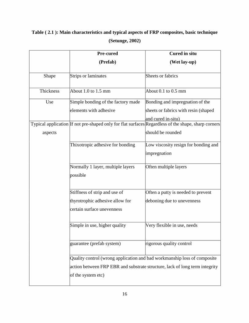
Table ( 2.1 ): Main characteristics and typical aspects of FRP composites, basic technique
(Setunge, 2002) ............................................................................................................................. 16
Table ( 4.1 ): Element Types for ANSYS Models ........................................................................ 41
Table ( 4.2 ): Material Properties of Concrete for ANSYS column Model ................................. 43
Table ( 4.3 ): material properties of steel reinforcement .............................................................. 46
Table ( 4.4 ): Material Properties of CFRP for ANSYS. .............................................................. 48
Table ( 4.5 ): Study Specimens Naming ...................................................................................... 50
Table ( 4.6 ):Nonlinear Analysis Control Commands in ansys .................................................... 56
Table ( 4.7 ):Output Control Commands. ..................................................................................... 56
Table ( 4.8 ): Nonlinear Algorithm and Convergence Criteria Parameters. ................................. 57
Table ( 4.9 ): Advanced Nonlinear Control Settings .................................................................... 57
Table ( 5.1 ): Comparison of the finite element modeling and experimental data ....................... 60
Table ( 5.2 ):Ductility ratios.......................................................................................................... 62
Table ( 5.3 ):Effect of fiber orientation ......................................................................................... 65

X
8 List Of Figures
Figure ( 2.1 ) Glass fiber fabric Carbon fibers ................................................................................ 8
Figure ( 2.2 ):Carbon fiber fabric .................................................................................................... 9
Figure ( 2.3 ): Single aramid fiber and ramid fiber fabric ........................................................... 11
Figure ( 2.4 ): the difference confinement actions provided by steel and FRP wrapping ............ 11
Figure ( 2.5 ): Triaxial state of stress in FRP jackets .................................................................... 12
Figure ( 2.6 ): Column failures in Kobe 1995 earthquake ............................................................ 13
Figure ( 2.7 ): (a) Hand lay-up CFRP sheets. (b) Application of prefabricated strips .................. 15
Figure ( 3.1 ): Response of concrete in compression ................................................................... 24
Figure ( 3.2 ): Stress-deflection relation for concrete in tension .................................................. 25
Figure ( 3.3 ): Stress-deflection relation for reinforced tension.................................................... 26
Figure ( 3.4 ): Tensile Stress‐strain Curve for Typical Reinforcing Steel Bar (ASTM A615, 1995)
....................................................................................................................................................... 27
Figure ( 3.5 ): Stress‐Strain Relationships for FRP, (ISIS, 2006)................................................. 28
Figure ( 3.6 ): Uniaxial Stress‐Strain Behavior of Concrete ......................................................... 29
Figure ( 3.7 ): Modified Hognestad Model (Basappa & and Rajagopal, 2013)............................ 29
Figure ( 3.8 ): Change in Topology of Finite Elements ................................................................ 30
Figure ( 3.9 ): Fixed Crack Model ................................................................................................ 32
Figure ( 3.10 ): Rotated Crack Model ........................................................................................... 33
Figure ( 3.11 ): 3D failure Surface for Concrete, [ANSYS 2014]. ............................................... 34
Figure ( 3.12 ): Linear Elastic-Perfect Plastic Model ................................................................... 35
Figure ( 4.1 ): Solid65 Geometry (ANSYS Mechanical APDL Manual Set, 2014) ..................... 39
Figure ( 4.2 ): Link180 Geometry (ANSYS Mechanical APDL Manual Set, 2014).................... 40
Figure ( 4.3 ): SOLID181 Homogeneous Structural Solid Geometry (ANSYS Mechanical APDL
Manual Set, 2014) ......................................................................................................................... 40
Figure ( 4.4 ): Shell181 Geometry (ANSYS Mechanical APDL Manual Set, 2014) ................... 41
Figure ( 4.5 ): Compressive Uniaxial Stress‐Strain Curve for Concrete ...................................... 42
Figure ( 4.6 ):Stress‐Strain Curve for Steel Reinforcement .......................................................... 47
Figure ( 4.7 ):Geomertry ............................................................................................................... 51
Figure ( 4.8 ): Volumes Created in ANSYS ‐ column Model. ..................................................... 51
Figure ( 4.9 ): Mesh of the Concrete and Steel Plates – column Model ...................................... 53
Figure ( 4.10 ): Meshing of CFRP Layer in ANSYS – column Model ........................................ 54
Figure ( 4.11 ): Plane of Symmetry – column Model ................................................................... 54
Figure ( 4.12 ): Loading Plate – column Model............................................................................ 55
Figure ( 5.1 ): Comparison of the stress-strain of the finite element modelling and experimental
tests ............................................................................................................................................... 59
Figure ( 5.2 ): Definition of ductility ratio .................................................................................... 61

XI
Figure ( 5.3 ): Stress-strain curves of square RC columns ........................................................... 62
Figure ( 5.4 ): Contours of axial compressive stress of concrete at mid-height of square columns
....................................................................................................................................................... 63
Figure ( 5.5 ):FRP tensile strain distribution in specimen A–3 .................................................... 64
Figure ( 5.6 ):Effect of fiber orientation ....................................................................................... 65

XII
9 List Of Symbols And Abbreviation
fcʹ Concrete compressive strength.
Ec Modulus elasticity of concrete.
fc Uniaxial crushing strength of concrete.
ft Ultimate uniaxial tensile strength of concrete.
fcb Ultimate biaxial compressive strength of concrete.
f1 Ultimate compressive strength of concrete for a state of biaxial
compression superimposed on hydrostatic stress state σha.
f2 Ultimate compressive strength of concrete for a state of uniaxial
compression superimposed on hydrostatic stress state.
Es Modulus elasticity of steel.
fy Yield strength of steel.
εy The strain at which steel yields.
fu Peak strength of steel.
εu The strain at which peak strength of steel is achieved.
fs The strain at which steel facture occurs.
εmax The strain at which fracture of steel occurs.
fs The stress at which steel facture occurs.
ν Poisson’s ratio.
EX Modulus of elasticity in x‐direction.
FRP Fiber-reinforced polymer.
RC Rinforced concrete
CFRP Carbon Fiber-Reinforced Polymers
μ Ductility ratios

1
Chapter 1
Introduction

2
1 Chapter1
Introduction
1.1 Background
The strengthening of reinforced concrete (RC) structures using advanced fiber-reinforced
polymer (FRP), and in particular the behavior of FRP-strengthened RC structures is a topic
which has become very popular in recent years. This popularity has arisen due to the need to
maintain and upgrade essential infrastructure in all parts of the world, combined with the well-
known advantages of FRP, such as good corrosion resistance and ease for site handling due to
their light weight. The continuous reduction in the material cost of FRP composites has also
contributed to their popularity. Reinforced concrete (RC) Columns with carbon fiber-reinforced
polymer CFRP composites offer an attractive solution to enhance the strengthening of columns.
(Teng, Chen, Smith, & Lam, 2001)
While experimental methods of investigation are extremely useful in obtaining information about
the composite behavior of FRP and reinforced concrete, the use of numerical models helps in
developing a good understanding of the behavior at lower costs .
In this research, a three dimensional non-linear finite element analysis model for strengthening
of reinforced concrete columns with carbon fiber reinforced polymers (CFRP) will be presented.
The model will make use of the commercial Finite Element modeling software ANSYS to study
the effects of different parameters that are important in the response of the strengthened columns.
1.2 Problem statement
Rehabilitation of old building is more economical than rebuilding them . That`s why the
behavior of strengthening techniques should be understood to make the best decision for
rehabilitation and helpful to save time and cost.
The behavior of reinforced concrete column strengthened externally with CFRP is highly
affected by the way in which these composites are applied to the column. In this research, a
nonlinear finite element model of RC column strengthened with CFRP will be investigated in
order to achieve the best utilization of this strengthening technique in terms of load bearing
capacity and possible failure modes.

3
1.3 Aim and objectives
The aim of this research is to develop a 3D non linear finite element model of reinforced
concrete columns externally strengthened with CFRP using the commercial Finite Element
Modeling software ANSYS, in order to investigate behavior of these columns. The following
objectives are set to achieve the aim of the study:
1. Identify the suitable consecutive element types available in ANSYS library that are capable
of modeling the behavior of RC columns externally strengthened with CFRP. (Concrete, steel
reinforcement bars, interface between concrete and steel, loading plates, CFRP, and interface
between concrete and CFRP).
2. Develop three dimensional finite element model to simulate the behavior of reinforced
concrete columns externally strengthened with CFRP.
3. Conduct a validation and a verification process of the model by comparing results obtained
from the model with observations obtained from experimental columns tests available in the
literature.
4. Conduct a parametric study using ANSYS to evaluate the effect of different parameters on
the behavior of strengthened columns.
1.4 Methodology
To complete this work the following steps were conducted:
Step 1: Review for available literature for the finite element modeling and experimental works related
to strengthening of reinforced concrete column with Carbon Fiber-Reinforced polymers
(CFRP) will be conducted.
Step 2: A non-linear three dimensional finite element model will be developed to simulate the behavior
of reinforced concrete columns externally strengthened with Carbon Fiber-Reinforced Polymers
(CFRP), using the commercial finite element modeling software ANSYS
Step 3: Analysis of the model.
Step 4: Draw conclusions and suggest recommendations.

4
1.5 Layout of the thesis
This thesis consists of six chapters, which are arranged in a logical sequence for the reader to
follow. Chapter 1: discusses The plan of this thesis Chapter 2 a background about Fiber
Reinforced Polymers FRP and concrete and reinforcement . Chapter 3 Mechanical Behavior and
Finite Element Modeling of Materials. Chapter 4 Building of ANSYS Finite Element Models,
Chapter 5: Verification of ANSYS Finite Element Models and Parametric Study, and Chapter 6:
Conclusions and Recommendations .

5
Chapter 2
Literature Review

6
2 Chapter 2
Literature Review
2.1 Introduction
In this chapter, a background about Fiber Reinforced Polymers FRP (constituents, advantages,
disadvantages, types) is presented. Typical applications of CFRP for external strengthening
of RC columns, installation techniques of CFRP in strengthening applications, and finally,
literature works about FE analysis of RC columns strengthened with CFRP using ANSYS
are be presented.
2.2 Constituents of Fiber Reinforced Polymers
Fiber-reinforced polymer(FRP), also Fiber-reinforced plastic, is a composite material made of a
polymer matrix reinforced with fibers. The fibers are usually glass, carbon, or aramid, although
other fibers such as paper or wood or asbestos have been sometimes used. The polymer is
usually an epoxy, vinylester or polyester thermosetting plastic, and phenol formaldehyde resins
are still in use. FRPs are commonly used in the aerospace, automotive, marine, and construction
industries. Composite materials are engineered or naturally occurring materials made from two
or more constituent materials with significantly different physical or chemical properties which
remain separate and distinct within the finished structure. Most composites have strong, stiff
fibers in a matrix which is weaker and less stiff. The objective is usually to make a component
which is strong and stiff, often with a low density. Commercial material commonly has glass or
carbon fibers in matrices based on thermosetting polymers, such as epoxy or polyester resins.
Sometimes, thermoplastic polymers may be preferred, since they are moldable after initial
production. There are further classes of composite in which the matrix is a metal or a ceramic.
For the most part, these are still in a developmental stage, with problems of high manufacturing
costs yet to be overcome. Furthermore, in these composites the reasons for adding the fibers (or,
in some cases, particles) are often rather complex; for example, improvements may be sought in
creep, wear, fracture toughness, thermal stability, etc (Martin, 2013).

7
2.3 Advantages and Disadvantages of Fiber Reinforced Polymers
FRP materials for use in concrete strengthening applications have a number of key advantages
over conventional reinforcing steel. Some of the most important advantages include (CSC.TR-
N55, 2000) :
1. Do not corrode electrochemically, and have demonstrated excellent durability in a
number of harsh environmental condition.
2. Have extremely high strength‐to weight ratios (typically weigh less than one fifth the
weight of steel, with tensile strengths that can be as much as 8 to 10 times as high).
3. Their installation is easy and simple with no need for temporary support.
4. Have low thermal conductivity.
FRP materials also have a number of potential disadvantages (ACI 440R‐07., 2007):
1. The relatively high cost of the materials.
2. The risk of fire, vandalism or accidental damage, unless the strengthening
is protected.
3. The relatively low elastic modulus of FRPs as compared with steel.
2.4 Types of FRP Materials Used in Construction Applications
The type of fibers used as the reinforcement is the basics for classification of FRP composites.
There are three types of fibers dominating civil engineering industry: glass, carbon and aramid
fibers.
2.4.1 Glass fibers
Glass fibers are a processed form of glass, which is composed of a number of oxides (mostly
silica oxide), together with other raw materials (such as limestone, fluorspar, boric acid, clay).
They are manufactured by drawing those melted oxides into filaments ranging from 3 Mm to 24
Mm ,Figure (2.1) shows the glass fiber fabric. There are five forms of glass fibers used as the
reinforcement of the matrix material: chopped fibers, chopped strands, chopped strand mats,
woven fabrics, and surface tissue. The glass fiber strands and woven fabrics are the forms most
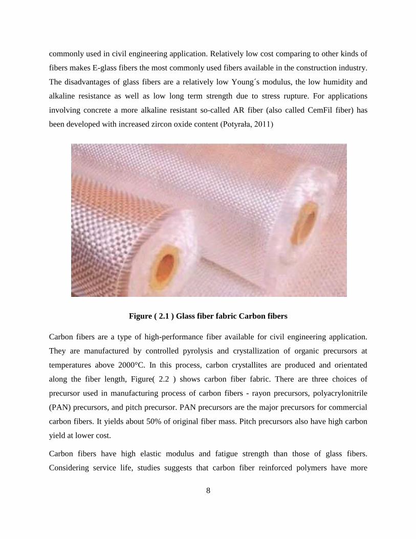
8
commonly used in civil engineering application. Relatively low cost comparing to other kinds of
fibers makes E-glass fibers the most commonly used fibers available in the construction industry.
The disadvantages of glass fibers are a relatively low Young´s modulus, the low humidity and
alkaline resistance as well as low long term strength due to stress rupture. For applications
involving concrete a more alkaline resistant so-called AR fiber (also called CemFil fiber) has
been developed with increased zircon oxide content (Potyrała, 2011)
Figure ( 2.1 ) Glass fiber fabric Carbon fibers
Carbon fibers are a type of high-performance fiber available for civil engineering application.
They are manufactured by controlled pyrolysis and crystallization of organic precursors at
temperatures above 2000°C. In this process, carbon crystallites are produced and orientated
along the fiber length, Figure( 2.2 ) shows carbon fiber fabric. There are three choices of
precursor used in manufacturing process of carbon fibers - rayon precursors, polyacrylonitrile
(PAN) precursors, and pitch precursor. PAN precursors are the major precursors for commercial
carbon fibers. It yields about 50% of original fiber mass. Pitch precursors also have high carbon
yield at lower cost.
Carbon fibers have high elastic modulus and fatigue strength than those of glass fibers.
Considering service life, studies suggests that carbon fiber reinforced polymers have more

9
potential than aramid and glass fibers. Their disadvantages include inherent anisotropy (reduced
radial strength), comparatively high energy requirements in their production as well as relatively
high costs (Potyrała, 2011)
Figure ( 2.2 ):Carbon fiber fabric
2.4.2 Aramid fibers
Aramid or aromatic polyamide fiber is one of the two high-performance fibers used in civil
engineering application. It is manufactured by extruding a solution of aromatic polyamide at a
temperature between -50°C and -80°C into a hot cylinder at 200°C. Fibers left from evaporation
are then stretched and drawn to increase their strength and stiffness. During this process, aramid
molecules become highly oriented in the longitudinal direction , Figure(2.3) shows Single aramid
fiber and aramid fiber fabric . Aramid fibers have high static, dynamic fatigue, and impact
strengths. The disadvantages are: low compressive strength (500-1000 MPa), reduced long-term
strength (stress rupture) as well as sensitivity to UV radiation. Another drawback of aramid
fibers is that they are difficult for cutting and machining (Potyrała, 2011)
2.5 FRP Applications for External Strengthening of RC Columns
2.5.1 Axial Compression
Strength enhancement can be achieved by using steel confinement as well as FRP confinement.
However FRP-strengthened concrete behaves differently from steel- strengthened concrete.

10
Therefore already established design guidelines for steel strengthened concrete columns cannot
be applied for FRP strengthened columns. As shown in Figure(2.4), the confinement actions
provided by steel and FRP wrapping are different. This behavior is due to the linear behavior
(without any yield points) of carbon fiber composites. After the initial linearly elastic phase,
steel displays a yielding plateau. Therefore after reaching the maximum stress corresponding to
yielding, the confining pressure remains constant. In the contrary, FRP wrapping continues
to provide continuously increasing confining pressure until it fails (elastic behavior).In designing
the FRP strengthening system for columns, it is necessary to estimate the strength enhancement
of concrete due to FRP composite confinement. This confining action depends on the strain in
FRP composite which is same as the lateral strain of concrete (lateral dilation).
Therefore the passive confining pressure provided by the externally bonded FRP composites
depends on the lateral dilation of concrete. Therefore constitutive model for concrete which can
predict the lateral dilation of concrete is ideal in estimating the passive confining pressure
provided by the FR The maximum confining pressure provided by FRP composites is related to
the amount and strength of FRP and the diameter of the strengthened concrete core. However,
the ultimate strength of the strengthened concrete is closely related to the failure strain of
the FRP wrapping reinforcement.
As the FRP is subjected to tension in hoop direction, eventual failure occurs when its hoop
tensile strength is reached. Many researchers have noted that the strain measured in the
confining FRP at rupture is in many cases lower than the ultimate strain of FRP tested for
tensile strength. The recorded hoop strains corresponding to rupture had a range of 50 to 80%
of the failure strain obtained in the tensile tests This reduction is due to the following reasons:
The triaxial state of stress of the wrapping reinforcement.The quality of the execution
If the surface preparation for FRP application is not good enough, some part of the
circumferential strain is used to stretch the fibers. Moreover, fibers may be damaged at
improperly rounded edges or local protrusionThe curve shape of the wrapping
reinforcement
Size effects when applying multiple layers
Figure (2-5) shows the concept of composite action, where the FRP jacket provides
longitudinal load carrying capacity as well as lateral confinement (it undergoes both longitudinal

11
and lateral strains). This behavior depends on the fiber arrangement and bond interface
characteristics. The ultimate stress and strain are reduced with a possibility of micro-
buckling and de-lamination. Therefore failure of the member occurs at a lower circumferential
strain than in case of no composite action. In case of no composite action, the FRP jacket is
subjected to lateral strain only and fails due to either fiber collapse or de- lamination
between plies. This failure takes place at a circumferential strain lower than the ultimate strain.
Depending on the loading condition (axial loading, shear and bending) the load- carrying
capacity of the column should be calculated according to appropriate confinement models.
(Setunge, 2002)
Figure ( 2.3 ): Single aramid fiber and ramid fiber fabric
Figure ( 2.4 ): the difference confinement actions provided by steel and FRP wrapping

12
Transverse compressive stress when in composite action
Confining pressure
Axial tensile stress due to lateral expansion
Figure ( 2.5 ): Triaxial state of stress in FRP jackets
2.5.2 Tensile Strengthening
FRP composites can be used to provide additional tensile strength to concrete members. It
depends on the design tensile strength of FRP and the ability to transfer stress into the substrate .
The tensile strength contribution of FRP can be directly calculated using Hooke’s law because of
its linear-elastic behavior. (Setunge, 2002)
2.5.3 Ductility
The collapse of and severe damage to many buildings and bridges in recent earthquakes have
highlighted the need for the seismic retrofit of seismically inefficient structures. Most of
the structural failures during recent earthquakes were attributed to poor column behavior.
Figure (2.6) shows three photos of column failures during Kobe 1995 earthquake. These failures
are due to inadequacy of confining reinforcement and bad detailing, which resulted in improper
confinement. In concrete structures, the ability to withstand strong earthquakes depends mainly
on the formation of plastic hinges and their capability of energy absorption and dissipation
without a major loss of strength capacity.
Within the plastic hinge, all the inelastic deformations are assumed to occur. The region outside
the hinge is assumed to remain elastic at all times. It is preferable to design structures with strong
columns and weak beams with plastic hinges forming in the beams and not in columns.
However, it may not always be possible to design structures Using steel reinforcement is the
traditional method of increasing ductility. Recent advances in FRP technology have proven that

13
FRP composites can be used to increase the ductility of like this, and hinges may develop in
columns.
Figure ( 2.6 ): Column failures in Kobe 1995 earthquake
concrete columns. Methods of improving ductility using FRP composites are described here in
brief .The purpose of seismic retrofit of RC columns is to achieve a sufficient level of
deformation ductility to dissipate seismic energy before one of the failure modes becomes
critical. The displacement ductility factor or the curvature ductility factor has been commonly
used to quantify the ductility of the seismic performance of a structure. In order to achieve a
target displacement ductility factor, μΔ, it is possible to find the thickness of the FRP jacket. The
method is explained in FIB Bulletin 14, 2001 and is as follows.
Equivalent plastic hinge length Lp for a given column is calculated based on the yield stress and
diameter of longitudinal rebars.

14
2.6 Strengthening Techniques using FRP
The strengthening techniques are concerned with the application of FRP as structural
reinforcement bonded to an existing concrete substrate structure. The technique can be used
under different conditions and at different locations of the structural member taking into account
all specifications and requirements.
2.6.1 Basic technique
The most widely used FRP strengthening technique is the manual application of wet lay-up
(hand lay-up) or prefabricated systems using cold cured adhesive bonding. The main and the
important feature of this technique is that the fibers of externally bonded FRP composites are in
parallel as practicable with the direction of principal tensile stresses. Typical applications of the
hand lay-up and prefabricated systems are illustrated in Figure( 2.7).
The basic technique of FRP strengthening described here refers to the manual application of
FRP reinforcement to an existing member. A two-part cold cured bonding agent (normally
epoxy-based) is used to achieve bonding. The basic technique involves three acting elements
Substrate and Adhesive/Resin and FRP reinforcement
FRP composite is bonded to an existing structure to enhance its strength. The material type of
that structure is the substrate. The behavior of the thus strengthened structure heavily depends on
a good concrete substrate and the preparation of the concrete surface. the initial conditions of the
concrete surface in terms of strength, carbonation, unevenness, imperfections,cracks, type and
possible corrosion of internal steel reinforcement, humidity, level of chloride and sulphate ions,
etc. should be known.
reinforcement. It may have to impregnate “wet lay-up” types of FRP system depending on the
type of FRP reinforcement.
For example in MBrace FRP strengthening systems, they use cold curing epoxy resin systems.
MBT-MBrace Resicem is a newly developed cementitious epoxy matrix FRP reinforcement
Depending on the application of the FRP composites, they can be categorized as follows:

15
Figure ( 2.7 ): (a) Hand lay-up CFRP sheets. (b) Application of prefabricated strips
2.6.1.1 Prefab or pre-cured strips or laminates
These FRP strips are provided as fully cured composites, which have their final shape, strength
and stiffness. They are mostly available as thin strips or laminates (thickness about 1.0 to 1.5
mm), similar to steel plates. For this type of strip the adhesive provides the bond between the
strip and the concrete only.
2.6.1.2 Wet lay-up (hand lay-up) or cured in situ sheets or fabrics
These FRP materials are available as “dry fiber”, which means that no resin is inside the FRP
before applying, or “prepreg”, having a very small amount of resin already inside the sheet
before applying. In the latter case, the amount of resin is not sufficient for polymerization.
For these types of sheets the application of the adhesive is required to both bond the sheet to the
concrete and to impregnate the sheet.
16
Table ( 2.1 ): Main characteristics and typical aspects of FRP composites, basic technique
(Setunge, 2002)
Pre-cured
(Prefab)
Cured in situ
(Wet lay-up)
Shape Strips or laminates Sheets or fabrics
Thickness About 1.0 to 1.5 mm About 0.1 to 0.5 mm
Use Simple bonding of the factory made
elements with adhesive
Bonding and impregnation of the
sheets or fabrics with resin (shaped
and cured in-situ) Typical application
aspects
If not pre-shaped only for flat surfaces Regardless of the shape, sharp corners
should be rounded
Thixotropic adhesive for bonding Low viscosity resign for bonding and
impregnation
Normally 1 layer, multiple layers
possible
Often multiple layers
Stiffness of strip and use of
thyrotrophic adhesive allow for
certain surface unevenness
Often a putty is needed to prevent
deboning due to unevenness
Simple in use, higher quality Very flexible in use, needs
guarantee (prefab system) rigorous quality control
Quality control (wrong application and bad workmanship loss of composite
action between FRP EBR and substrate structure, lack of long term integrity
of the system etc)
17
2.7 Previous Works in the FE Modeling of RC Columns Strengthened with
CFRP.
(Tavio & Tata, 2009) worked on predicting nonlinear behavior and stress-strain relationship of
rectangular strengthened reinforced concrete columns with ANSYS. a nonlinear finite element
modeling and analysis of rectangular normal-strength reinforced concrete columns strengthened
with transverse steel under axial compressive loading. In this study, the columns were modeled
as discrete elements using ANSYS nonlinear finite element software. Concrete was modeled
with 8-noded SOLID65 elements that can translate either in the x-, y-, or z-axis directions from
ANSYS element library. Longitudinal and transverse steels were modeled as discrete elements
using 3D-LINK8 bar elements available in the ANSYS element library. The nonlinear
constitutive law of each material was also implemented in the model. The results indicate that the
stress-strain relationships obtained from the analytical model using ANSYS are in good
agreement with the experimental data. This has been confirmed with the insignificant difference
between the analytical and experimental, i.e. 5.65 and 2.80 percent for the peak stress and the
strain at the peak stress, respectively. The comparison shows that the ANSYS nonlinear finite
element program is capable of modeling and predicting the actual nonlinear behavior of
strengthened concrete column under axial loading. The actual stress-strain relationship, the
strength gain and ductility improvement have also been confirmed to be satisfactorily.
(Saravanan, 2014) worked on analytical modeling for confinement of high strength concrete
columns with glass fiber reinforced polymer wrapping fiber reinforced polymer strengthened
columns have been developed for new construction rehabilitation of concrete structures such as
piers or piles in civil engineering field. The design oriented confinement model predominant in
designing FRP strengthened concrete columns. The design model is directly based on in
interpretation of experimental result. In this study one model is presented for reinforced concrete
columns externally reinforced with fiber reinforced polymer wraps using finite element method
adopted by ANSYS software. The finite element model was developed using for concrete and
the three dimensional layer elements for the fiber reinforced polymer composites. The result
obtained from those finite element analysis results were compared on the experimental data for
respective concrete column with different conditions from researcher. The prediction of ANSYS
model agreed with the experimental results.

18
(Julien & Emmanuel, 2015)Worked on experimental study on rc columns retrofitted by frp and
subjected to seismic loading. Evaluate the strength and ductility enhancement resulting from the
use of longitudinally bonded FRP. For this purpose, the paper presents the results of
experimental investigation conducted on six real scale RC columns tested under a quasi-static
loading path intended to be representative of a seismic solicitation: reversed lateral cyclic
loading and constant axial load. The main parameter tested was the FRP configuration. Those
tests helped us to analyze the behavior of RC columns depending on the FRP confinement
(CFRP jacket) and on flexural reinforcement (carbon plates) and allowed us to determine the
influence of these parameters on the ultimate strength, on ductility, on stiffness, on dissipated
energy, and then to conclude about the behavior of the externally reinforced columns.
(Barbato & Hu,D., 2014) Worked on simple and efficient finite element modeling of reinforced
concrete columns strengthened with fiber-reinforced polymers a frame finite element (FE) that
is able to accurately estimate the load-carrying capacity and ductility of reinforced concrete (RC)
circular columns strengthened with externally-bonded fiber-reinforced polymers (FRP). This
frame FE can model collapse mechanisms due to concrete crushing, reinforcement steel yielding,
and FRP rupture. The adopted FE considers distributed plasticity with fiber discretization of the
cross-sections in the context of a force-based formulation, and uses advanced nonlinear material
constitutive models for reinforcing steel and unstrengthened, steel-strengthened, and FRP-
strengthened concrete.
(Jijin & Preetha, 2012) Worked on effect of gfrp jacketing & cfrp jacketing on rc columns of
different cross-sectional shapes frp is an advanced composite material (ACM) that is relatively
new material to civil engineering. It holds a better choice than reinforcing steel in certain
applications. In order to attain large deformation before failure occurs and to enhance an
adequate load resistance capacity, RC columns has to be laterally jacketed. Jacketing RC column
with FRP improves column performance not only by carrying some fraction of axial load applied
to it but also by providing lateral confining pressure to the column externally. In this work effect
of circular, rectangular and square columns on GFRP jacketing and CFRP jacketing having same
cross-sectional area were analysed. RC columns were analysed in ANSYS 15. The percentage
area reduction of concrete in RC columns when FRP jacketing is provided is found out.

19
(Feng, 2002) worked on experimental research and finite element analysis of square concrete
columns strengthened by FRP sheets under uniaxial compression In order to investigate the
behavior of square concrete columns strengthened by fiber reinforced polymer (FRP) sheets, five
specimens were tested and analyzed using finite element method (FEM). The loading behaviors
of the strengthened concrete columns under uniaxial compression can be divided into three
phases. As confirmed by experimental results, finite element analysis (FEA) can effectively
simulate the behavior of square columns strengthened by FRP sheets when the proper numerical
model is adopted. Based on the test and FEA, the stress distributions and the stress development
are obtained. This provides theoretical understanding for establishing the stress-strain curve
model. It is suggested that the FEM is a powerful method for further research on numerical test
and parameter analysis.
(Prabhakaran, 2015) worked on comparative study on gfrp jacketed rc columns and cfrp
jacketed rc columns of different shapes . Column jacketing with FRP sheets plays an important
role in enhancing the performance of RC column. FRP is an Advanced Composite Material
(ACM) that is relatively new material to civil engineering. It holds a better choice than
reinforcing steel in certain applications. In order to attain large deformation before failure occurs
and to enhance an adequate load resistance capacity, RC columns has to be laterally jacketed.
Jacketing RC column with FRP improves column performance not only by carrying some
fraction of axial load applied to it but also by providing lateral confining pressure to the column
externally. In this work a comparative study on GFRP jacketed RC columns and CFRP jacketed
RC columns of different shapes having same cross-sectional area were analyzed. Buckling
analysis on RC columns of circular, rectangular and square cross-sectional shapes has been done
in ANSYS 15. FRP Jacketing increases the load carrying capacity of all RC columns. CFRP
Jacketed RC columns shows a better load carrying capacity than GFRP Jacketed RC Columns
when both axial and eccentric loadings were applied in circular, rectangular and square cross-
sectional shapes.
(Athanasios, Theodoros, & Georgia, 2007) worked on three-dimensional finite element analysis
of reinforced concrete columns strengthened by fiber reinforced polymer sheets . an analytical
investigation of concrete columns with conventional longitudinal and transverse steel
reinforcement and external confinement by FRP sheets is performed. The study focuses on the

20
behavior of old type columns with extremely low concrete strength and stirrup spacing leading to
bars’ elastic buckling failure when compressed. The investigation includes also viability of the
use of external FRP confinement in delaying or preventing elastic buckling of bars under
compression. A Drucker – Prager type model with an advanced approach in estimating plasticity
parameters is inserted in finite element (FE) code. Results from numerical analyses are compared
against performed experiments. Stress concentrations in concrete core and on FRP jacket are also
investigated for analyses cases that have been carried out.
(Hajsadeg & Alaee, 2010) worked on numerical analysis of rectangular reinforced concrete
columns strengthened with FRP jacket under eccentric loading . The paper is devoted to
investigate the behavior of square RC columns strengthened with FRP wraps using ANSYS
software. A total of four prisms of size 150×300×500mm and 210×210×500mm were simulated
by the FE model and the results were compared with the experimental test results reported in
literature. Very good agreement was found between the model results and the test results.
Therefore, the mod-el was validated. As predicted, it was found that the effectiveness of FRP
jackets under eccentric loads is re-duced in comparison with concentric loads. In the next step,
the interaction diagrams of axial force and bend-ing moment for columns strengthened with FRP
wrap was obtained from the model results. They were compared with the interaction diagrams
proposed by the design guideline of ACI 440.2R-08. It was found that the load carrying
capacities resulted from the model are generally higher than those recommended by ACI 440.2R-
08.
2.8 Concluding Remarks
1. The studies showed that FRP effective in strengthening the concrete columns
2. Some of the researcher use ANSYS to develop their models
3. The FRP jacketing is a very good alternative for strengthening of existing square, circular
and rectangular RC column and it helps in economical construction by concrete reduction
in designing new RC columns
4. Finite element analysis is used to study the mechanical behaviour of reinforced concrete
columns with bars suffering from premature buckling under compression as well as the
effect of external confinement by FRP sheet jacket.

21
5. The model provides accurate prediction for concrete columns under uniform elastic
confinement by FRP materials

22
CHAPTER 3
Numerical Modeling of
Reinforced Concrete Material

23
3 CHAPTER 3
Numerical Modeling of Reinforced
3 Concrete Material
3.1 Introduction
In this chapter, the mechanical behavior and finite element modeling basics of materials will be
discussed as concrete, steel reinforcement, and carbon fiber reinforced polymer (CFRP) are
presented. Further, failure criteria and modeling approaches for each material are introduced
3.2 Mechanical Behavior of Materials
The mechanical behavior of concrete , steel plates , steel reinforcement and FRP are explained
in the following sections .
3.2.1 Concrete
3.2.1.1 Reinforced Concrete in Compression
Concrete as a material consists of hard particles of rocks mixed with cement paste to glue these
particles together. When the concrete is subjected to compression, the stresses will seek through
the hard particles. In compression the concrete starts to crack when the capacity of the glue
between the particles is reached. This happens long before the strength of the concrete is
exceeded.
At first the cracks are micro cracks between the hard particles and the paste. The micro cracks
are the reason for some of the strains in the concrete. They will continue to develop, and at some
point they become macro cracks and a fracture occurs. The stiffness of concrete decreases as the
number of cracks increases. This is called the softening of the concrete, and it is the reason for
the concave response of the material. When dealing with compression in reinforced concrete . A
compression response for normal strength concrete is shown on Figure (3.1). The figure also
shows important parameters for modelling with concrete in compression.
To calculate the stiffness for a certain stress in the concrete the secant modulus of elasticity has
to be known. Approximate values for the secant modulus E = 0-0.4as listed in the design codes.

24
The compressive strength of the concrete is fan and the modulus of elasticity at this stress level is
shown as E on the figure (3.1). (Rasmussen, 2012)
Figure ( 3.1 ): Response of concrete in compression
3.2.1.2 Reinforced Concrete in Tension
The first part of the stress-strain curve resembles the response of the uncracked concrete. The
compatible strains in the concrete and reinforcement result in a linear elastic response, where the
influence of the reinforcement is, most often, insignificant .The strain capacity is negative in the
beginning due to shrinkage.
The second part of the curve starts when the tensile capacity of the concrete is reached, and the
concrete starts to crack. The cracks will form one by one at locations where the concrete's
strength is exceeded. Where the cracks form, the stress level in the concrete will drop, because
the reinforcement is taking over. Due to this, the stress distribution in the steel and concrete in
the length of the member is no longer uniform.
While cracks are forming, there will still be concrete tensile stresses in the cracked sections. As
the width of the cracks become larger, stresses will decrease. They vanish when there is no more
cohesion in a crack. At this point the reinforcement has taken over completely in the cracked
sections. The decrease of the concrete's stiffness due to cracking is called the softening of the
concrete.

25
In the areas between adjacent cracks the concrete is still able to carry tensile stress, because
stress in the reinforcement is transmitted to the concrete by means of bond shear stresses. This is
the effect called tension stiffening, which indicates that the concrete applies stiffness to the
member in addition to the stiffness of the bare reinforcement. (Rasmussen, 2012)
When the applied load increases, the amount of tension stresses in the concrete will decrease
with the increase in number of cracks, because more areas become crack zones. The tension-
stiffening effect will also be decreased due to internal cracking.
At a certain level the member will stabilize and no more cracks will form. The tension-stiffening effect
will drop and the response of the member will approach the one of a fully cracked when the reinforcement
swim to yield. Around when yielding the reinforcement happens the elongated of the reinforcement bar
will affects the bond strength.
The bar thickness has been reduced due to Poisson's ratio and therefore the bond strength is reduced as
well. Due to additional stiffness from the concrete between cracks, the response will never be coincident
with the bare reinforcement bar, (Rasmussen, 2012)
Figure ( 3.2 ): Stress-deflection relation for concrete in tension

26
Figure ( 3.3 ): Stress-deflection relation for reinforced tension.
3.2.2 Steel Reinforcement
Figure (3.4) shows a typical stress‐strain relationship for reinforcing steel. Steel is initially
linear‐elastic for stress less than the initial yield stress. At ultimate tensile strain, the
reinforcement begins to neck and strength is reduced. At a maximum strain, the steel
reinforcement fractures and load capacity is lost.
This steel response may be defined by a few material parameters. These include the elastic
modulus (Es), the yield strength (fy), the strain at which peak strength is achieved (εu), the peak
strength (fu), the strain at which fracture occurs (εmax), and the capacity prior to steel fracture (fs),
(ASTM A615, 1995).For general engineering applications, an elastic‐plastic constitutive
relationship, either with or without strain hardening, is normally assumed for ductile reinforcing
steel.
In an elastic hardening model it is assumed that steel shows some hardening after it yields.An
elastic‐perfectly plastic model generally yields acceptable results for the response prediction of
RC members (Neale, Ebead, Abdel Baky, Elsayed, & Godat, 2005).

27
Figure ( 3.4 ): Tensile Stress‐strain Curve for Typical Reinforcing Steel Bar (ASTM A615,
1995)
3.2.3 Fiber Reinforced Polymer (FRP)
FRP composite materials are not homogeneous. Their properties are dependent on many factors,
the most important of which are, (ISIS, 2006):
1. The relative proportions of fiber and matrix (volume fractions).
2. The mechanical properties of the constituent materials (fiber, matrix, and any additives).
3. The orientation of the fibers within the matrix.
4. The method of manufacture
Figure (3.5) shows typical stress‐strain curves for fibers, matrices, and the FRP materials that
result from the combination of fibers and matrix.
Unidirectional FRP materials are typically linear elastic up to failure, and do not exhibit the
yielding behavior that is displayed by conventional reinforcing steel, (ISIS, 2006).

28
Figure ( 3.5 ): Stress‐Strain Relationships for FRP, (ISIS, 2006).
3.3 Finite Element Modeling of Materials
The finite element modeling of materials are explined in following sections , crack models are
explained for materials but it weren’t taken in the validation of results.
3.3.1 Finite Element Modeling of Concrete
The uniaxial stress‐strain behavior of concrete in compression is shown in Figure
(3.6).Various mathematical models are available to approximate this nonlinear behavior namely:
linearly elastic‐perfectly plastic model, inelastic‐ perfectly plastic, Hognestad, and piecewise
linear model. In the present study a modified Hognestad mathematical model figure(3.7) has
been used for the approximation of the stress‐strain behavior of concrete,
1. Initial tangent modulus of elasticity increases with an increase in compressive
strength. So, the elastic modulus (EC) is given by (ACI 8.5.1):
Ec=4700 f cʹ (3 – 1)
Where 𝑓𝑐 is compressive strength of concrete at 28 days in MPa. The stress-strain relation
initially must satisfy the Hooke’s law.

29
Figure ( 3.6 ): Uniaxial Stress‐Strain Behavior of Concrete
Figure ( 3.7 ): Modified Hognestad Model (Basappa & and Rajagopal, 2013)
2. The strain at maximum stress increases as the compressive strength increases:
ɛo=2fC
Ec (3-2)
3. The raising portion of the stress strain curve resembles a parabola with vertex
at the maximum stress:
f =EC ɛ
1+(ε
ε0)2
(3-3)

30
Where, (f) is stress for a value of strain in stress‐strain relationship of concrete. The stress‐strain
behavior of concrete under tension includes raising part and descending part. The raising part is
slightly curved, approximated either as straight lines or parabola. The descending part drops
rapidly with increased elongation after the maximum stress is crossed.
3.3.2 Finite Element Modeling of Cracks in Concrete
3.3.2.1 Discrete crack model
The discrete crack model assumes a separation between element edges. The approach suffers
from two drawback. First, it implies a continuous change in nodal connectivity, which does not
fit the nature of the finite element displacement method. Secondly, the crack is constrained to
follow predefined path along the element edges. A class of problems exists, however, whereby
the orientation of the discrete crack is not necessarily the prime subject of interest. One may
think of fracture in the form of a straight separation band, the location of which is known in
advance, or of discrete cracks along the interface between concrete and reinforcement.
Furthermore, engineering problems exist whereby a mechanism of discrete cracks can be
imagined to occur in a fashion similar to yield line mechanisms. For suck cases, the above
drawbacks vanish and one may use a simple form of discrete cracks with a predefined
orientation.
Figure ( 3.8 ): Change in Topology of Finite Elements

31
With the change of topology and the redefinition of nodal points, the narrow bandwidth of the
stiffness matrix is destroyed and a greatly increased computational effort results in this model
figure(3.8). Moreover, the lack of generality in crack orientation has made the discrete crack
model unpopular. In spite of these shortcomings, the use of discrete crack models in finite
element analysis offers
certain advantages over the other methods. For those problems that involve a few dominant
cracks, the discrete crack approach offers a more realistic description of the cracks, which
represent strain discontinuities in the structure. Such discontinuities are correctly characterized
by the discrete crack model (Kotsovos & Pavlovic, 1995).
3.3.2.2 Smeared Crack Model
The need for a crack model that offers automatic generation of cracks and complete generality
in crack orientation, without the need of redefining the finite element topology, has led the
majority of investigators to adopt the smeared crack model. Rather than representing a single
crack, the smeared crack model represents many finely spaced cracks perpendicular to the
principal stress direction.
This approximation of cracking behavior of concrete is quite realistic, since the fracture
behavior of concrete is very different from that of metals. In concrete fracture is preceded by
microcracking of material in the fracture process zone, which manifests itself as strain
softening. This zone is often very large relative to the cross section of the member due to the
large size of aggregate.
With this continuum approach, the local displacement discontinuities at cracks are distributed
over some tributary area within the finite element. In contrast to the discrete crack concept, the
smeared crack concept fits the nature of the finite element displacement method, since the
continuity of the displacement field remains intact.
Although this approach is simple to implement and is, therefore, widely used. It has
nevertheless a major drawback, which is the dependency of the results on the size of the finite
element mesh used in the analysis. When large finite elements are used, each element has a
large effect on the structural stiffness. When a single element cracks, the stiffness of the entire
structure is greatly reduced. Higher order elements in which the material behavior is

32
established at a number of integration points do not markedly change this situation, because, in
most cases, when a crack takes place at one integration point, the element stiffness is reduced
enough so that a crack will occur at all other integration points of the element in the next
iteration. Thus, a crack at an integration point does not relieve the rest of the material in the
element, since the imposed strain continuity increases the strains at all other integration
points.
The overall effect is that the formation of a crack in a large element results in the softening
of a large portion of the structure. The difficulty stems from the fact that a crack represents a
strain discontinuity, which cannot be modeled correctly within a single finite element in which
the strain varies continuous.
Smeared crack models can be categorized into: 1. Fixed smeared crack model as shown
figure(3.9), 2. Rotating smeared crack model as shown figure(3.10). The Orientation of a crack
in the fixed smeared crack model is fixed during the entire computational process. While, a
rotating smeared crack model allows the orientation of the crack to co-rotate with the axes of
principal strain (Rots & Blaauwendraad, 1989).
Figure ( 3.9 ): Fixed Crack Model

33
Figure ( 3.10 ): Rotated Crack Model
3.3.3 Finite Element Failure Criteria of Concrete
Figure (3.11) represents the 3‐ D failure surface for states of stress that are biaxial or nearly
biaxial. If the most significant nonzero principal stresses are in the σxp and σyp directions, the
three surfaces presented are for σzp slightly greater than zero, σzp equal to zero, and σzp
slightly less than zero.
Although the three surfaces, shown as projections on the σxp ‐ σyp plane, are nearly equivalent
and the 3‐D failure surface is continuous, the mode of material failure is a function of the sign
of σzp. For example, if σxp and σyp are both negative and σzp is slightly positive, cracking would be
predicted in a direction perpendicular to the σzp direction. However, if σzp is zero or slightly
negative the material is assumed to crush, (ANSYS, 2014).
In ANSYS, a concrete element cracks when the principal tensile stress in any direction lies
outside the failure surface. After cracking, the elastic modulus of the concrete element is set to
zero in the direction parallel to the principal tensile stress direction.
Crushing occurs when all principal stresses are compressive and lie outside the failure surface;
subsequently, the elastic modulus is set to zero in all directions and the element effectively
disappears, (ANSYS, 2014).

34
Figure ( 3.11 ): 3D failure Surface for Concrete, [ANSYS 2014].
3.3.4 Reinforcing Steel Models
Modeling steel reinforcement is much easier than modeling concrete since it is not
environmental conditions or time dependent. A uniaxial stress-strain relationship would
suffice to define the material properties needed to carry out the analysis of reinforced
concrete structures. For practical purposes, reinforcing steel exhibit the same behavior in
tension as in compression,. The behavior of steel exhibits a linear elastic behavior as shown
in figure (3.12). Since steel reinforcement is used in concrete construction in the form of
reinforcing bars or wire, it is not necessary to introduce the complexities of three-
dimensional constitutive relations for steel. For computational convenience, it even often
suffices to idealize the one dimensional stress-strain relation for steel.
Reinforcing steel can be modeled as:
1. Smeared model
2. Embedded model
3. Discrete model

35
In the Smeared model, the reinforcing steel is assumed to be distributed over the concrete
element at a certain orientation angle. A composite concrete-steel constitutive relation is
used in this case, which, however, requires that perfect bond be assumed between concrete
and steel. An embedded steel model is useful in connection with higher order isoparametric
concrete elements.
The reinforcing steel is considered as an axial member built into the isoperimetric element
such that its displacements are consistent with those of the element. Such a model again
implies perfect bond between concrete and steel. A drawback to this model is the high
computational effort and time required to the analysis. The most widely used model
represents the reinforcement with discrete one-dimensional truss elements, which are
assumed to be pin connected and possess two degrees of freedom at each node.
Alternatively, column elements can also be used, in which case, three degrees of freedom
are allowed at each end of the bar element. In either case, the one-dimensional reinforcing
bar elements can be easily superimposed on the two-dimensional concrete element mesh.
A significant advantage of the discrete representation, in addition to its simplicity, is that it
can include the slip of reinforcing steel with respect to the surrounding concrete.
Figure ( 3.12 ): Linear Elastic-Perfect Plastic Model

36
3.3.5 Finite Element Modeling of FRP
the unidirectional lamina has three mutually orthogonal planes of material properties (i.e., xy, xz,
and yz planes). The xyz coordinate axes are referred to as the principal material coordinates
where the x direction is the same as the fiber direction, and the y and z directions are
perpendicular to the x direction. It is a so‐called orthotropic material, [Barbero,2014, Kaw,
2006]. CFRP composites can be modeled either using isotropic linear elastic model or
orthotropic linear elastic model (Mohammad H. , 2015), In this study, the properties of the CFRP
composites were nearly the same in any direction perpendicular to the fibers. Thus, the
properties in the y direction were the same as those in the z direction. Orthotropic linear elastic
model for CFRP composites was used throughout this study.
Failure criteria are used to assess the possibility of failure of a material. Doing so allows the
consideration of orthotropic materials, which might be much weaker in one direction than
another, (ANSYS Mechanical APDL Manual Set, 2014).
Failure criteria are used to learn if a layer has failed due to the applied loads. Many failure
criteria are used in FE software packages for composite materials. The most used criteria are:
maximum strain failure criteria, maximum stress failure criterion, Tsai‐Wu failure criteria, and
physical failure criteria, like: Hashin fiber failure criterion, Hashin matrix failure criterion, Puck
fiber failure criterion, and Puck matrix failure criterion (ANSYS Mechanical APDL Manual Set,
2014).

37
CHAPTER 4
BUILDING OF
ANSYS FINITE
ELEMENT MODELS

38
4 CHAPTER 4
BUILDING OF ANSYS FINITE ELEMENT MODELS
4.1 Introduction
The finite element method is a numerical analysis technique for obtaining approximate
solutions to a wide variety of engineering problems. ANSYS is a general purpose finite
element modeling package for numerically solving a wide variety of problems which
include static/dynamic structural analysis (both linear and nonlinear), heat transfer and
fluid problems, as well as acoustic and electro‐magnetic problems.
The external strengthening of reinforced concrete columns with carbon fiber reinforced
polymers (CFRP) had been analyzed using finite element models in ANSYS 14. Many
self‐learning tutorials and manuals were used as references in preparing the FE models using
ANSYS.
The experimental investigations were used to model and verify the strengthening of RC
column with CFRP using ANSYS. (Mohammad, Farshid, & Amir, 2010)
4.2 Modeling Assumptions
The following are the modeling assumptions made column models in the present study
to provide reasonably good simulations for columns the complex behavior:
1. Concrete and steel are modeled as isotropic and homogeneous materials.
2. Poisson’s ratio is assumed to be constant throughout the loading history.
3. Steel is assumed to be an elastic‐perfectly plastic material and identical in
tension and compression.
4. Perfect bond exists between concrete and steel reinforcement.
5. Perfect bond exists between concrete and CFRP fabric. The perfect bond
assumption used in the structural modeling doesnʹt cause a significant error in the
predicted load‐deflection response.
6. The CFRP material is assumed to be especially orthotropic‐transversely
isotropic. That is, the material properties in the two directions that are both
perpendicular to the fiber direction are identical.
7. The CFRP fabric is assumed to carry stress along its axis only.

39
8. Time‐dependent nonlinearities such as creep, shrinkage, and temperature
change are not included in this study.
4.3 Selection of Element Types Using ANSYS
In this section, the description of element types used for all materials used in ANSYS models
is presented. These materials are: concrete, steel reinforcement, and carbon fiber reinforced
polymer (CFRP). Elements used in thesis models are widely used and recommended by
ANSYS and previous researchers.
4.3.1 Concrete
An eight‐node solid element, Solid65, was used to model the concrete. The solid element
has eight nodes with three degrees of freedom at each node: translations in the nodal
local x, y, and z directions. The element is capable of plastic deformation, cracking in three
orthogonal directions, and crushing. The geometry and node locations for this element type
are shown in Figure (4‐1), (ANSYS Mechanical APDL Manual Set, 2014).
4.3.2 Steel Reinforcement
A Link180 element was used to model steel reinforcement. The element is a uniaxial
tension‐compression element with three degrees of freedom at each node: translations in the
nodal x, y, and z directions. Plasticity, creep, rotation, large deflection, and large strain
capabilities are included. This element is shown in Figure (4‐2), (ANSYS Mechanical
APDL Manual Set, 2014).
Figure ( 4.1 ): Solid65 Geometry (ANSYS Mechanical APDL Manual Set, 2014)

40
4.3.3 Loading and Supporting Steel Plates
The Solid185 element is used for the modeling of loading and supporting steel plates. This
element is defined by eight nodes having three degrees of freedom at each node: translations
in the nodal x, y, and z directions. The element is capable of plasticity, hyperelasticity, stress
stiffening, creep, large deflection, and large strain capabilitiess. This element is shown in
Figure (4‐3).
Figure ( 4.2 ): Link180 Geometry (ANSYS Mechanical APDL Manual Set, 2014)
4.3.4 Carbon Fiber Reinforced Polymer (CFRP)
Shell181 element is used for the modeling Carbon Fiber Reinforced Polymer (CFRP). It is a
four‐node element with six degrees of freedom at each node: translations in the x, y, and z
directions, and rotations about the x, y, and z‐ axes. SHELL41 is well‐suited for linear,
large rotation, and/or large strain nonlinear applications. The geometry, node locations,
and the coordinate system are shown in Figure (4‐4), [ANSYS, 2014].
Figure ( 4.3 ): SOLID181 Homogeneous Structural Solid Geometry (ANSYS Mechanical
APDL Manual Set, 2014)

41
Figure ( 4.4 ): Shell181 Geometry (ANSYS Mechanical APDL Manual Set, 2014)
The element types used for modeling of model is summarized in Table (4‐1).
Table ( 4.1 ): Element Types for ANSYS Models
Material Type ANSYS Element
Reinforced Concrete Soild65
Steel Reinforcement Link180
Carbon Fiber Reinforced
Polymer(CFRP)
Shell181
4.4 Material Properties
The following sections will be explained the matilials properties of finite elements model
with ANSYS , and the failure criterias for each material .
4.4.1 Concrete
Material Model refers to the Solid65 element. The Solid65 element requires linear isotropic
and multilinear isotropic material properties, in addition to selection of failure criteria of
concrete.
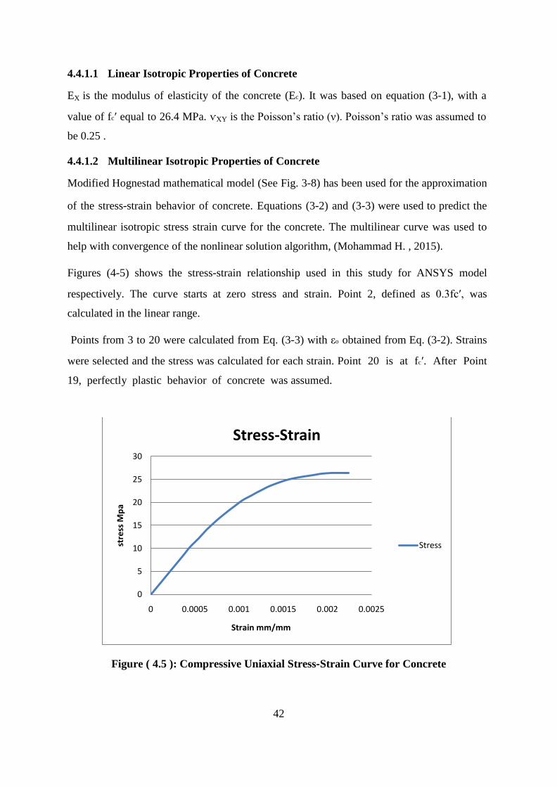
42
4.4.1.1 Linear Isotropic Properties of Concrete
EX is the modulus of elasticity of the concrete (Ec). It was based on equation (3‐1), with a
value of fcʹ equal to 26.4 MPa. ѵXY is the Poisson’s ratio (ν). Poisson’s ratio was assumed to
be 0.25 .
4.4.1.2 Multilinear Isotropic Properties of Concrete
Modified Hognestad mathematical model (See Fig. 3‐8) has been used for the approximation
of the stress‐strain behavior of concrete. Equations (3‐2) and (3‐3) were used to predict the
multilinear isotropic stress strain curve for the concrete. The multilinear curve was used to
help with convergence of the nonlinear solution algorithm, (Mohammad H. , 2015).
Figures (4‐5) shows the stress‐strain relationship used in this study for ANSYS model
respectively. The curve starts at zero stress and strain. Point 2, defined as 0.3fcʹ, was
calculated in the linear range.
Points from 3 to 20 were calculated from Eq. (3‐3) with εo obtained from Eq. (3‐2). Strains
were selected and the stress was calculated for each strain. Point 20 is at fcʹ. After Point
19, perfectly plastic behavior of concrete was assumed.
Figure ( 4.5 ): Compressive Uniaxial Stress‐Strain Curve for Concrete
0
5
10
15
20
25
30
0 0.0005 0.001 0.0015 0.002 0.0025
stre
ss M
pa
Strain mm/mm
Stress-Strain
Stress

43
Parameters needed to define the material model for concrete in ANSYS models are shown in
Tables (4‐2).
Table ( 4.2 ): Material Properties of Concrete for ANSYS column Model
Element Type Material Properties
Soild65
Linear Isotropic
EX 24500 (MPa)
ѵXY 0.25
Multilinear Isotropic
Point Strain Stress (MPa)
1 0 0
2 0.00034 7.92
Soild65 3 0.00044 10.16
4 0.00054 12.23
5 0.00064 14.16
6 0.00074 15.96
7 0.00084 17.60
8 0.00094 19.08
9 0.00104 20.40
10 0.00114 21.57
11 0.00124 22.58
12 0.00134 23.46
13 0.00144 24.19
14 0.00154 24.80
15 0.00164 25.30
16 0.00184 25.98
17 0.00194 26.19
18 0.00204 26.32
19 0.00214 26.39
20 0.0022 26.40

44
Table ( 4.2 ): Continue Material Properties of Concrete for ANSYS column Model
Concrete
Open Shear Transfer Coef. 0
Closed Shear Transfer Coef. 1
Uniaxial Cracking Stress 2.7 MPa
Uniaxial Crushing Stress 26.4 MPa
Biaxial Crushing Stress Default
Hydrostatic Pressure Default
Hydro Biax Crushing Stress Default
Tensile Crack Factor 0.8
4.4.1.3 Failure Criteria of Concrete
Implementation of the Willam and Warnke (1975) concrete material model in ANSYS requires
that different constants to be defined. These constants are: (ANSYS Mechanical APDL Manual
Set, 2014)
1. Shear transfer coefficients for an open crack;
2. Shear transfer coefficients for a closed crack;
3. Uniaxial tensile cracking stress;
4. Uniaxial crushing stress (positive);
5. Biaxial crushing stress (positive);
6. Ambient hydrostatic stress state for use with constants 7 and 8; 7. Biaxial
crushing stress (positive) under the ambient hydrostatic stress state (constant 6);
8. Uniaxial crushing stress (positive) under the ambient hydrostatic stress state (constant 6);
9. Stiffness multiplier for cracked tensile condition.
The shear transfer coefficient represents a shear strength reduction factor for subsequent loads
that induce sliding (shear) across the crack face, [Chansawat et al., 2009]. Typical shear
transfer coefficients range from 0.0 to 1.0, with 0.0 representing a smooth crack (complete
loss of shear transfer) and 1.0 representing a rough crack (no loss of shear transfer), (ANSYS

45
Mechanical APDL Manual Set, 2014). For an open crack, the shear transfer coefficient varied
between 0.05 and 0.50 in many studies of reinforced concrete structures, (Mohammad H. , 2015).
In this study, many analysis attempts had been done to determine the appropriate values of shear
transfer coefficients based on comparison of FE load‐displacement values with experimental
results. The open and closed cracks shear transfer coefficients used in this study for column
models are shown in Tables (4‐2).
The uniaxial cracking stress of concrete (tensile strength) is based upon the modulus of rupture.
Modulus of rupture of concrete is a more variable property than the compressive strength and is
about 8 to 15 percent of the compressive strength, (Mohammad H. , 2015). In ANSYS, when
cracking occurs at an integration point of Solid65 element, material properties are adjusted to
effectively model a “smeared band” of cracks, rather than discrete cracks.
When a principal stress at an integration point in a concrete element exceeds the tensile
strength, stiffness is reduced to zero in that principal direction perpendicular to the cracked plane
(ANSYS Mechanical APDL Manual Set, 2014). In this study, values of uniaxial cracking stress
of concrete used for column models are shown in Tables (4‐2).
In ANSYS, crushing of concrete element occurs when all principal stresses are
compressive and lies outside the failure surface; subsequently, the elastic modulus is
set to zero in all directions, and the element effectively disappears, (Mohammad H. , 2015). The
uniaxial crushing stress of concrete in is based on the uniaxial compressive strength tested in the
experimental investigations. The failure surface of concrete can be specified with a minimum of
two constants, ft and fc. The remainder of the variables in the concrete model was left to
default based on (Basappa & Rajagopa, 2013) equations.
4.4.2 Steel Reinforcement
Material model the Link180 element. Material model number 2 is used to model the
reinforcement, while material model number 3 is used to model the stirrups.
The Link180 element is assumed to be bilinear isotropic and is based on the von Mises failure
criteria, (ANSYS Mechanical APDL Manual Set, 2014). The bilinear model requires the

46
Yield Stress (fy), as well as the Hardening Modulus (tangent modulus of the plastic region) of
steel to be defined. Elastic Modulus (EX) was also defined, and Poisson’s Ratio (ѵx) was
assumed to be 0.3.Tables (4‐3) show material properties of steel reinforcement used for
ANSYS column models respectively.
Table ( 4.3 ): material properties of steel reinforcement
Element Type
Material Properties
Link180
Linear Isotropic
𝐸𝑋 200000 MPa
ѵ𝑋𝑌 0.3
Bilinear Isotropic
Yield stress 476 MPa
Tangent Modulus 20 MPa
Section (SECID: 1, SECTYPE: link Shell)
(in ANSYS)
Link180
Linear Isotropic
𝐸𝑋 200000 MPa
ѵ𝑋𝑌 0.3
Bilinear Isotropic
Yield stress 345 MPa
Tangent Modulus 20 MPa
The steel for the finite element models was assumed to be an elastic‐perfectly plastic material
and identical in tension and compression. Figure (4‐6) shows the assumed stress‐strain curve for
steel reinforcement, (Mohammad H. , 2015).

47
4.4.3 Carbon Fiber Reinforced Polymer (CFRP)
Material model refer to CFRP fabric which was modeled using the shell181 element. CFRP
composites were assumed to be especially orthotropic and transversely isotropic; that is,
mechanical properties are the same in any direction perpendicular to the fibers. Definition of
CFRP in ANSYS model requires definition of linear isotropic material properties,
sectionproperties, and failure criteria. Parameters needed to define the material model for CFRP
in ANSYS column models are shown in Tables (4‐4).
Figure ( 4.6 ):Stress‐Strain Curve for Steel Reinforcement
4.4.3.1 Linear Orthotropic Properties
The stress‐strain relationship of CFRP is roughly linear up to failure. In this study, it was
assumed that the stress‐strain relationship for the CFRP laminates is linearly elastic.
To define the linear orthotropic model of CFRP in ANSYS, the following properties are
specified:

48
Elastic modulus in three directions (EX, EY and EZ).
Shear modulus for three planes (GXY, GXZ and GYZ).
Major Poisson’s ratio for three planes (ѵXY, ѵXZ and ѵYZ).
Table ( 4.4 ): Material Properties of CFRP for ANSYS.
Element Type Material Properties
Shell181
Linear Orthotropic
𝐸𝑋 230000 MPa
𝐸𝑌 12000 MPa
𝐸𝑍 12000 MPa
ѵ𝑋𝑌 0.3
ѵ𝑌𝑍 0.45
ѵ𝑋𝑍 0.3
𝐺𝑋𝑌 7000 MPa
𝐺𝑌𝑍 7000 MPa
𝐺ѵ𝑋𝑍 7000 MPa
Section (SECID: 3, SECTYPE: Shell)
Layer No. 1
Thickness of
layer
0.165 mm
Orientation 0 degree
Failure Criteria
Stress – XTEN 3430 MPa
Strain – XTEN 0.015

49
A local coordinate system for the CFRP shell element was defined where the x direction is the
same as the fiber direction, while the y and z directions were perpendicular to the x direction.
The elastic modulus in the fiber direction of the unidirectional CFRP material used in the
experimental studies was specified by the manufacturer, major Poissonʹs ratio was assumed, and
then, the elastic modulus in directions perpendicular to the fiber direction, minor Poissonʹ ratio,
and shear modulus were predicted using Rule of Mixture, as shown in tables (4‐4) .
4.4.3.2 Section Properties
The most important characteristic of a composite material is its layered configuration. Each
layer may be made of a different orthotropic material and may have its principal directions
oriented differently. For laminated composites, the fiber directions determine layer
orientation, (ANSYS Mechanical APDL Manual Set, 2014). To define the layered
configuration of CFRP fabric, the following shall be specified:
Number of layers.
Thickness of each layer (TK).
Orientation of the fiber direction for each layer (THETA).
4.4.3.3 Failure Criteria of CFRP
CFRP fabrics were modeled as linear elastic materials up to failure. Maximum strain failure
criteria and maximum stress failure criteria were used based on the longitudinal tensile
strength and maximum strain of the used CFRP fabrics,
4.5 Description of Experimental columns
In this section geometric details of column. The experimental investigation of (Mohammad,
Farshid, & Amir, 2010)was used to simulate the strengthening model in ANSYS. This
Experiment presents the results of the numerical analysis of square/rectangular reinforced
concrete (RC) columns strengthened with FRP jackets. The size of column 250×250×500 mm
was modeled and analysis was carried out using a non-linear finite element method. Two
parameters of wrap thickness and fiber orientation were considered.

50
4.5.1 Geometry
By taking advantage of the symmetry of the column , a quarter of full column was used for
modeling. This approach reduced computational time and computer disk space requirements
significantly. The concrete column was modeled as volumes, CFRP layers were modeled as
areas, and steel reinforcement were modeled as lines figure (4-7). Since a quarter of the column
is being modeled, the model is 500 mm long, with a cross‐section of 125 mm x 125 mm. The
CFRP fabric layer bonded to the column soft was modeled as an areas. The quarter of the
entire model including the created volumes for column model is shown in Figure (4‐8).
4.5.2 Study Specimens Naming
To discuss my results , naming of models to show the results it is important as show in table (4-
5)
Table ( 4.5 ): Study Specimens Naming
Name Data Number of layers
NS-R-1-200-0-40 Experimental 0
A-3 Experimental/Model 3
A-1 Model 1
A-3 Model 3
A-5 Model 5

51
Figure ( 4.7 ):Geomertry
Figure ( 4.8 ): Volumes Created in ANSYS ‐ column Model.

52
4.6 Meshing
Meshing of concrete , steel reinforcement , and FRP in Analyses model explain in the following
section .
4.6.1 Concrete
To obtain good results from the Solid65 element, the use of a rectangular mesh is
recommended (Wolanski, 2004; Kachlakev et al., 2001). Therefore, the mesh is set up such that
square or rectangular elements are created. The overall mesh of the concrete column model is
shown in Figure (4‐9)
4.6.2 Reinforcement
Ideally, the bond strength between the concrete and steel reinforcement should be considered.
However, in this study, perfect bond between materials was assumed.
To provide the perfect bond, the link element for the steel reinforcing was connected between
nodes of each adjacent concrete solid element, so the two materials shared the same nodes,
(Wolanski, 2004; Kachlakev et al., 2001).
The meshing of the reinforcement is a special case compared to the concrete volumes. No mesh
of the reinforcement is needed because individual elements are created in the modeling through
the nodes created by the mesh of the concrete volumes.
However, the necessary mesh attributes need to be set before each section of the reinforcement
is created.
4.6.3 CFRP Fabric Layer
CFRP sheets were meshed as shell elements as shown in figure (4-10) in such a way that its
nodes were oriented with adjacent concrete solid elements in order to satisfy the perfect bond
assumption. The command ʺmerge itemsʺ was used to merge separate nodes that have the same
location.
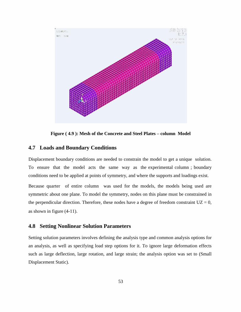
53
Figure ( 4.9 ): Mesh of the Concrete and Steel Plates – column Model
4.7 Loads and Boundary Conditions
Displacement boundary conditions are needed to constrain the model to get a unique solution.
To ensure that the model acts the same way as the experimental column ; boundary
conditions need to be applied at points of symmetry, and where the supports and loadings exist.
Because quarter of entire column was used for the models, the models being used are
symmetric about one plane. To model the symmetry, nodes on this plane must be constrained in
the perpendicular direction. Therefore, these nodes have a degree of freedom constraint UZ = 0,
as shown in figure (4‐11).
4.8 Setting Nonlinear Solution Parameters
Setting solution parameters involves defining the analysis type and common analysis options for
an analysis, as well as specifying load step options for it. To ignore large deformation effects
such as large deflection, large rotation, and large strain; the analysis option was set to (Small
Displacement Static).

54
Figure ( 4.10 ): Meshing of CFRP Layer in ANSYS – column Model
Figure ( 4.11 ): Plane of Symmetry – column Model

55
Figure ( 4.12 ): Loading Plate – column Model
4.8.1 Applied Loads
The force, P, applied at the steel plate is applied across the entire centerline of the loading
plate, as shown in figures (4‐12) .
In nonlinear analysis, the load applied to the structures must be increased gradually to
avoid non‐convergence. The total load applied to a finite element model is divided into a series
of load increments called load steps. At the completion of each incremental solution, the
stiffness matrix of the model is adjusted to reflect nonlinear changes in structural stiffness
before proceeding to the next load increment, (ANSYS Mechanical APDL Manual Set, 2014).
The ANSYS program uses Newton– Raphson equilibrium iterations for updating the model
stiffness.

56
Automatic time stepping in the ANSYS program predicts and controls load step sizes.
Based on the previous solution history and the physics of the models, if the convergence
behavior is smooth, automatic time stepping will increase the load increment up to a selected
maximum load step size. If the convergence behavior is abrupt, automatic time stepping will
bisect the load increment until it is equal to a selected minimum load step size. The maximum
and minimum load step sizes are required for the automatic time stepping, (ANSYS Mechanical
APDL Manual Set, 2014).
Nonlinear static snalysis type was utilized for columns models. Typical commands utilized in
the analysis are shown in Table (4‐6).
Table ( 4.6 ):Nonlinear Analysis Control Commands in ansys
Analysis Options Small Displacement Static
Calculate Prestress Effects No
Time at End of Load Step 1
Automatic Time Stepping On
Time Step Size 0.05
Minimum Time Step 0.001
Maximum Time Step 0.05
Write Items to Results File All Solution Items
Frequency Write Every Sub Step
The commands used to control the solver and outputs are shown in Table (4‐7).
Table ( 4.7 ):Output Control Commands.
Equation Solvers Sparse Direct
Number of Restart Files 1
Frequency Write Every Sub Step
The commands used for the nonlinear algorithm and convergence criteria are shown in Table
(4‐8). All values for the nonlinear algorithm are set to defaults.

57
Table (4‐9) shows the command used for the advanced nonlinear settings. ANSYS program
behavior upon non‐convergence for this analysis was set such that the program will terminate but
not exit. The rest of the commands were set to defaults
Table ( 4.8 ): Nonlinear Algorithm and Convergence Criteria Parameters.
Line Search On
DOF solution predictor Program Chosen
Maximum number of
iteration
100
Cutback control Cutback according to predicted number of iter.
Equiv. Plastic Strain 0.15
Explicit Creep ratio 0.1
Implicit Creep ratio 0
Incremental displacement 1,00,00,000
Points per cycle 13
Set Convergence Criteria
Label F U
Ref. Value Calculated Calculated
Tolerance 0.005 0.05
Norm L2 L2
Min. Ref. Not applicable Not applicable
Table ( 4.9 ): Advanced Nonlinear Control Settings
Program Behavior Upon Non‐convergence Terminate but do not exit
Nodal DOF Sol’n 0
Cumulative Iterations 0
Elapsed time 0
CPU time 0

58
CHAPTER 5
Results and discussion

59
5 CHAPTER 5
Results and discussion
5.1 Introduction
In this chapter, comparison FE results with experimental data are presented and discussion the
parametric study of the Effect of wrap thickness and Effect of fiber orientation .
5.2 Validation (comparison FE results with experimental data)
The validation of the FE analysis of the FRP-wrapped RC columns was checked with an
experimental study reported. specimens of A-3 (square) was selected for the validation of the FE
models. These specimen was the same as A-3 in our FE models, respectively. Fig.5.1 shows a
comparison between the stress-strain response of the control specimens obtained from the tests
and that resulted from the FE analysis (Mohammad, Farshid, & Amir, 2010).
Figure ( 5.1 ): Comparison of the stress-strain of the finite element modelling and
experimental tests
For better understanding of the FRP jacket effect on the behavior of the strengthened columns,
the stress-strain responses of unstrengthened specimens (NS-R-1-200-0-40) are also shown in
Fig. 5.1. In addition, the comparison of the finite element analysis (FEA) and the experimental
0
5
10
15
20
25
30
35
40
45
50
0 0.01 0.02 0.03 0.04
Stre
ss M
pa
Strain mm/mm
NS-R-1-200-3-40 (Exp)
A-3
NS-R-1-200-0-40 (Exp)
NS-R-1-200-0-40:experimental unstrengthened specimens.NS-R-1-200-3-40:experimental unstrengthened specimens.

60
results are presented in Table 5.1; in which f’cc and ɛccu are the maximum compressive stress and
strain of the strengthened columns, respectively. It can be seen that the FE analysis results are
very close to the test results. This means that the FE model is valid for predicting the behaviour
of specimens and can be used to conduct a parametric study.
Table ( 5.1 ): Comparison of the finite element modeling and experimental data
Specimens A-3
f’cc Exp 41.85 Mpa 4.6%
FE 43.84 Mpa
ɛccu Exp 0.0331 mm/mm 3.0%
FE 0.0341 mm/mm
5.3 Parametric study
This section discuss the effect of warp thickness and the orientation of FRP comparing with the
model results that have been done on A-3 .
5.3.1 Effect of wrap thickness
In this section, the effects of various wrap thicknesses on the behavior of the FRP-wrapped RC
columns are investigated. To assess the confinement effect on the ductility of the specimens, the
ductility ratios of all of the specimens were calculated. Ductility can be assessed by the ductility
ratio (Mohammad, Farshid, & Amir, 2010), μ, which is defined by:
𝝁 =𝐔𝐥𝐭𝐢𝐦𝐚𝐭𝐞 𝐝𝐢𝐬𝐩𝐥𝐚𝐜𝐞𝐦𝐞𝐧𝐭
𝐄𝐥𝐚𝐬𝐭𝐢𝐜 𝐝𝐢𝐬𝐩𝐥𝐚𝐜𝐞𝐦𝐞𝐧𝐭 (5-1)
The ultimate displacement is defined as the point at which the load drops 20% from the peak
load. The yield displacement is the yield point of an equivalent bi-linear response curve that
provides an equal area to that of the response curve, as shown in Fig. 5.2.
For specimens without a post-peak behaviour and for which the column failed at the peak point,
the last point is used for the ultimate displacement Fig. 5.3 and show the stress-strain response of
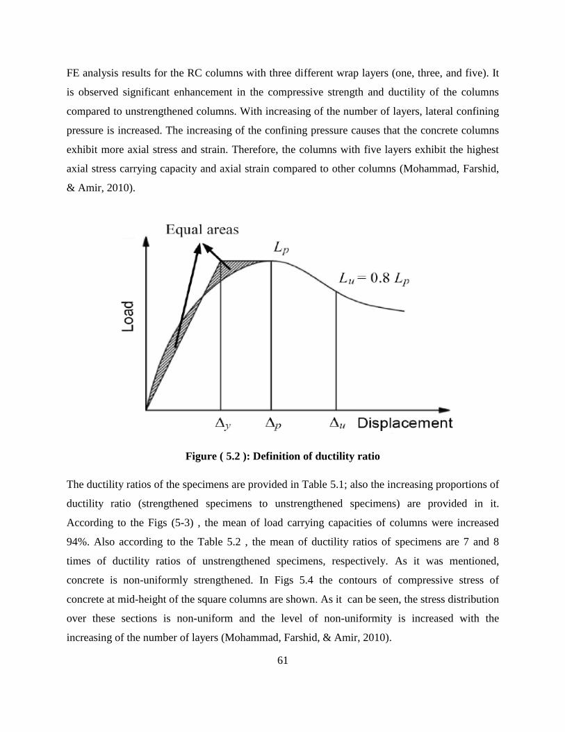
61
FE analysis results for the RC columns with three different wrap layers (one, three, and five). It
is observed significant enhancement in the compressive strength and ductility of the columns
compared to unstrengthened columns. With increasing of the number of layers, lateral confining
pressure is increased. The increasing of the confining pressure causes that the concrete columns
exhibit more axial stress and strain. Therefore, the columns with five layers exhibit the highest
axial stress carrying capacity and axial strain compared to other columns (Mohammad, Farshid,
& Amir, 2010).
Figure ( 5.2 ): Definition of ductility ratio
The ductility ratios of the specimens are provided in Table 5.1; also the increasing proportions of
ductility ratio (strengthened specimens to unstrengthened specimens) are provided in it.
According to the Figs (5-3) , the mean of load carrying capacities of columns were increased
94%. Also according to the Table 5.2 , the mean of ductility ratios of specimens are 7 and 8
times of ductility ratios of unstrengthened specimens, respectively. As it was mentioned,
concrete is non-uniformly strengthened. In Figs 5.4 the contours of compressive stress of
concrete at mid-height of the square columns are shown. As it can be seen, the stress distribution
over these sections is non-uniform and the level of non-uniformity is increased with the
increasing of the number of layers (Mohammad, Farshid, & Amir, 2010).

62
Table ( 5.2 ):Ductility ratios
DUCTILITY Unstrengthened
Ductility ratio
(mm/mm)
Strengthened
Ductility ratio
(mm/mm)
Proportion
Strengthened 𝜇unstrengthened 𝜇
Square columns 1.8 A-1 6 3.33
A-3 13.4 7.44
A-5 22.2 12.34
Figure ( 5.3 ): Stress-strain curves of square RC columns
This phenomenon is caused by the shape of the cross section. In fact, at any location of the cross
section different lateral pressure from FRP wrap is applied and therefore, the distribution of
compressive stress becomes non-uniform. In all models, the maximum axial compressive stress
occurs in the neighborhood of the corners and its minimum happens at the middle of the larger
sides. Also it is evident that the square specimens in comparison with rectangular specimens
0
10
20
30
40
50
60
0 0.01 0.02 0.03 0.04 0.05 0.06 0.07
Stre
ss M
pa
Strain mm/mm
Stress-strain curves
A-1
A-3
A-5

63
have more effective area of cross section in carrying higher compressive stress (see Figs 4 and 5)
that leads to the square specimens have more axial load carrying capacities in comparison with
the rectangular specimens. In Fig. 5.4 contour of strain for FRP jacket in hoop direction for
specimen R–3 is shown. All column models wrapped with one, three, or five layers of FRP failed
due to the rupture of FRP at near mid-height of the columns. Intensive stress concentration
occurred at the corners where contact between concrete and FRP was the highest. This high
outward contact force produced tensile strains in the FRP wrap in hoop direction (Mohammad,
Farshid, & Amir, 2010).
Figure ( 5.4 ): Contours of axial compressive stress of concrete at mid-height of square
columns
5.3.2 Effect of fiber orientation
In this section, the effect of fiber orientation of FRP jacket on the stress-strain response of
specimens A-3is considered. The fiber orientation 0°, ±15°, ±30°, and ±45° with respect to
horizon were considered. Fig (5-6) show the effect of the fiber orientation on the stress-strain

64
response of specimens A-3. Table 5.3 shows ductility ratios of the specimens A-3versus the fiber
orientation of the wrap. It was observed that the fiber orientation of wrap strongly affects the
stress-strain response of the specimens (Mohammad, Farshid, & Amir, 2010).
The hoop orientation of fibers (0°) results in the largest gain in ultimate stress, while the fiber
orientation of ±45° leads to the largest ultimate strain. The specimen shows lower decreasing of
axial load-carrying capacity in comparison with specimen A-3 however, they are not much
different in increasing of axial strain and ductility (Mohammad, Farshid, & Amir, 2010).
When the fiber-wrapped concrete is subjected to an axial compression loading, due to bonding
between concrete core and FRP jacket, FRP is deformed. In this case, considering the fiber
orientation of wrap more than 0°. the deformation causes the compression deformation of the
fibers and leading FRP wrap fail with more lateral expanding concrete core. This phenomenon
causes increasing the axial strain of specimens . However, fiber orientation (more than 0°) leads
to the applying less confining pressure to concrete core and concrete specimens exhibit less axial
stress. The increasing of the fiber orientation causes that the concrete specimens exhibit more
axial strain and less axial stress (Mohammad, Farshid, & Amir, 2010).
Figure ( 5.5 ):FRP tensile strain distribution in specimen A–3

65
Figure ( 5.6 ):Effect of fiber orientation
Table ( 5.3 ):Effect of fiber orientation
Specimens Fiber orientation
±0° ±15° ±30° ±45°
A-3 (𝜇 mm/mm) 13.4 12.9 20.5 44.2
0
5
10
15
20
25
30
35
40
45
50
0 0.05 0.1 0.15 0.2
Stre
ss M
pa
strain mm/mm
Effect of fibre orientation
0⁰
15⁰
30⁰
45⁰

66
CHAPTER 6
CONCLUSIONS AND
RECOMMENDATIONS

67
6 CHAPTER 6
CONCLUSIONS AND RECOMMENDATIONS
6.1 Conclusions
The important conclusions drawn from the study are listed below:
1. The finite element analysis results showed substantial increase in the axial compressive
strength and ductility of the FRP-wrapped RC columns compared with the unstrengthened
columns.
2. Strengthening the RC column by bonding a single layer of CFRP to the tension face
of the column increases strength of the column by 20%.
3. Increasing number of CFRP layers bonded to the column soffit increases the stiffness
of the column , increases its ultimate capacity.
4. Strengthening the RC column by bonding two layers of CFRP to faces of the
column increases the strength of the column by 25%.
5. Strengthening the RC column by bonding three layers of CFRP fabric to faces of the
column increases the strength of the column by 32%.
6. The gain in axial compressive strength was observed to be the highest in the columns
wrapped with the hoop orientation; but the highest axial strain and ductility were observed
in the columns wrapped with the fiber orientation of ±45° with respect to the horizon.
7. The wrap thickness has a significant effect on the strength and ductility of the columns.
Increasing the wrap thickness increases the strength and ductility of columns, considerably.
Increasing of axial load-carrying capacity of the square specimens is significantly higher
than that for rectangular specimens.
6.2 Recommendations
1. In this study, the commercial Finite Element analysis software (ANSYS) was used in
the analysis process. Comparative studies using other available Finite Element softwares
can be conducted to investigate which one can give more precise results comparing with
experimental investigations.
68
2. In this study, the external strengthening of RC column with CFRP was investigated.
Strengthening with other available Fiber Reinforced Polymer (FRP) materials
like Glass Fiber Reinforced Polymer (GFRP) can be studied to investigate the efficiency
of the strengthening technique using different materials with different properties.
3. In this study, the bond between concrete and CFRP fabric was assumed to be perfect.
Although this assumption did not cause a significant error in the obtained results
comparing with experimental investigations; the behavior of the concrete‐CFRP bond
and de‐bonding issues can be studied analytically to get more precise results especially
regarding failure modes.
4. In this study, the influence of some parameters on the overall response of the
strengthened RC columns has been investigated. These parameters are: effect of number
of CFRP layers, effect of CFRP length, and effect of CFRP inclination. Effect of other
parameters as column stiffness, column geometry, CFRP stiffness, and CFRP width on
the behavior of the strengthened RC columns can be also studied.

69
The Reference List

70
7 The Reference List
ACI 440R‐07. (2007). Report on Fiber‐Reinforced Polymer (FRP) Reinforcement for Concrete
Structures.
ANSYS Mechanical APDL Manual Set. (2014). Release 14.5. Southpointe: ANSYS Inc.
ASTM A615. (1995). Standard specification for deformed and plain billet steel bars for concrete
reinforcing. Newyourk: American society for testing and material.
Athanasios, I., Theodoros, C., & Georgia, E. (2007, July 16-18). Three-dimensional finite
element analysis of reinforced concrete columns strengthened by fiber reinforced polymer
sheets. Laboratory of Reinforced Concrete , pp. 1-10.
Barbato, M., & Hu,D. (2014). Simple and efficient finite element modeling of reinforced
concrete columns confined with fiber-reinforced polymers. Engineering Structures , 72, 113–
122.
Basappa, U., & Rajagopa, A. (2013). Modeling of CFRP Strengthened RCC Beam Using the
Nonlinear Finite Element Method. Journal of Structural Engineering , 40 (23), 169‐184.
Chansawa, K., Potisuk, T., Miller, T., Yim, S., & Kachlakev, D. (2009). E Models of GFRP and
CFRP Strengthening of Reinforced Concrete beams. Advances in Civil Engineering , 2009
(2009), 13.
Hajsadeg, M., & Alaee, F. J. (2010). Numerical analysis of rectangular reinforced concrete
columns confined with FRP jacket under eccentric loading. Advances in FRP Composites in
Civil Engineering , 658-661.
ISIS. (2006). An Introduction to FRP Composites for Construction. Canada: ISIS Educational
Module.
Jijin, V., & Preetha, P. (2012). Comparative study on GFRP jacketed rc columns and CFRP
jacketed rc columns of different shapes. International Journal of Engineering Research and
General Science. International Journal of Engineering Research and General Science , 3 (7),
475-488.
Julien, M., & Emmanuel, F. (2015). experimental study on rc columns retrofitted by frp and
subjected to seismic loading. Paris: Université Paris Est.
Kotsovos, D. M., & Pavlovic, M. N. (1995). Finite-element analysis for limit-state design.
Wiltshire: Thomas Telford.
Martin, A. M. (2013). Introduction of Fiber-Reinforced Polymers − Polymers and Composites:
Concepts, Properties and Processes. london: ISBN.

71
Mohammad, H. (2015). Non‐linear Finite Element Analysis of Reinforced. gaza, Palestine,
Palestine: The Islamic University of gaza.
Mohammad, H., Farshid, J. A., & Amir, S. (2010). Investigation on behaviour of
square/rectangular reinforced concrete columns retrofitted with frp jacket. Journal of Civil
Engineering & Management , 17 (3), p400-408.
Mohammed, A. (2015). Nonlinear Finite Element Analysis of RC Beams Strengthened with
Steel Fiber-Reinforced Concrete (SFRC) overlays. gaza, Palestine, Palestine: Islamic
university of gaza.
Neale, K., Ebead, U., Abdel Baky, H., Elsayed, W., & Godat, A. (2005). Modeling of Debonding
Phenomena in FRP‐Strengthened Concrete Beams and Slabs. Proceedings of the
International Symposium on Bond Behavior of FRP .
Potyrała, P. (2011). Use of Fiber Reinforced Polymer Composites in Bridge Construction. State
of the Art in Hybrid and All-Composite. catlonia: Construcció.
Prabhakaran, P. (2015). comparative study on GFRP jacketed rc columns and CFRP jacketed rc
columns of different shapes. International Journal of Engineering Research and General
Science .
Rasmussen, A. B. (2012). analytical and numerical midel of reinforced concrete in servicability
limit stat. Aarhus: AARHUS UNIVERSITY.
Rots, J. G., & Blaauwendraad, J. (1989). Crack Models for Concrete. Delft: HERON.
Saravanan, J. (2014). Experimental Study on RC Columns Wrapped With Hybrid FRP Sheets.
Journal of Structural Engineering , 1-15.
Setunge. (2002). Review of strengthening techniques using externally bonded FRP composites.
CRC.
Tavio, T., & Tata, A. (2009). Predicting Nonlinear Behavior and Stress-Strain Relationship of
Rectangular Confined Reinforced Concrete Columns with ANSYS.
Teng, J., Chen, F., Smith, S. T., & Lam, L. (2001). FRP: Strengthened RC Structures. london:
WileyCDA.
Recommended