Failure, Repair and Overhaul of 5 MW Right Angle Reduction Gear Box
Authors:
Haseeb Bukhari
Ahtsham Ahmed
Presenter/Author
Haseeb Bukhari: The author has more than 7 years experience in maintenance and Reliability of Turbomachinery. The author has also written Technical Paper in other Journals as well. Author has carried out RCAs for equipment failures and have also been part of many Projects Ahtsham Ahmed: Author has been associated with Turbomachinery for the past 05 years. Author posses good knowledge of Reliability and specializes in RCA Studies
Abstract L-1403A &B are 5 MW Right Angle –Double reductions gearboxes installed between Turbine (TP-1403) and Cooling water Pump (P-1403). Both gearboxes reported high vibration after 15 months of continuous operation one after the other. Vibration had a continuous increasing trend. CSI® was used to check the gearboxes that both showed looseness spectrum.
During inspection of L-1403 B Gear Box, broken tooth of LS Bevel Gear was observed. While L-1403 A inspection revealed pitting on HS gears. Gearboxes were repaired in house by increasing interference of bevel pinion with shaft.
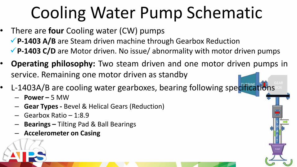
Cooling Water Pump Schematic • There are four Cooling water (CW) pumps P-1403 A/B are Steam driven machine through Gearbox Reduction P-1403 C/D are Motor driven. No issue/ abnormality with motor driven pumps
• Operating philosophy: Two steam driven and one motor driven pumps in service. Remaining one motor driven as standby
• L-1403A/B are cooling water gearboxes, bearing following specifications – Power – 5 MW – Gear Types - Bevel & Helical Gears (Reduction) – Gearbox Ratio – 1:8.9 – Bearings – Tilting Pad & Ball Bearings – Accelerometer on Casing
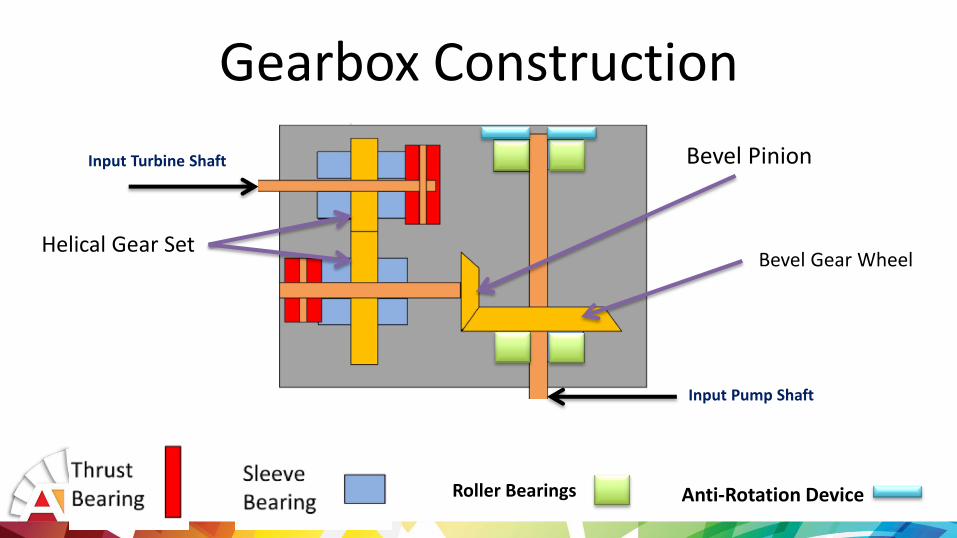
Gearbox Construction
Helical Gear Set
Bevel Pinion
Bevel Gear Wheel
Roller Bearings Anti-Rotation Device
Input Turbine Shaft
Input Pump Shaft
Observations and Anomalies • On Jan,14 Abnormal noise from L-1403A gearbox and increased gear
backlash was observed during window inspection • Similar abnormal noise with lower extent observed from L-1403B
(damaged one) Gearbox. Hence its inspection was planned for latter • Surveillance Frequency was increased on Both pumps post this
incident • Accelerometer probes Vibrations reading on both increased but
remained under Alarm limits

Observations and Anomalies • On March 12th, during startup , L-1403 B was reported to have very
high vibration Data was collected using CSI® • Data showed high vibration and failure of Gears. It was then
immediately shutdown and inspected.
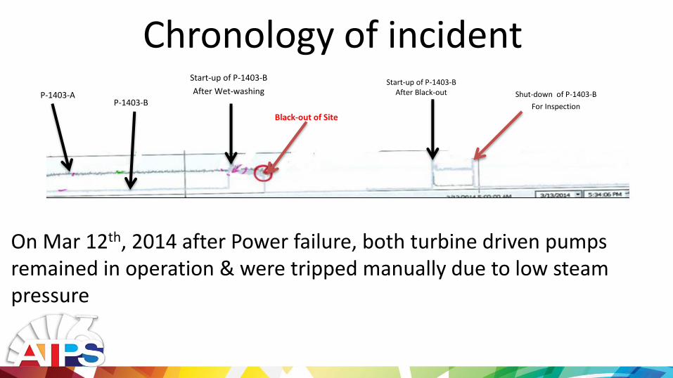
Chronology of incident P-1403-A
P-1403-B
Start-up of P-1403-B
After Wet-washing
Black-out of Site
Start-up of P-1403-B After Black-out Shut-down of P-1403-B
For Inspection
On Mar 12th, 2014 after Power failure, both turbine driven pumps remained in operation & were tripped manually due to low steam pressure
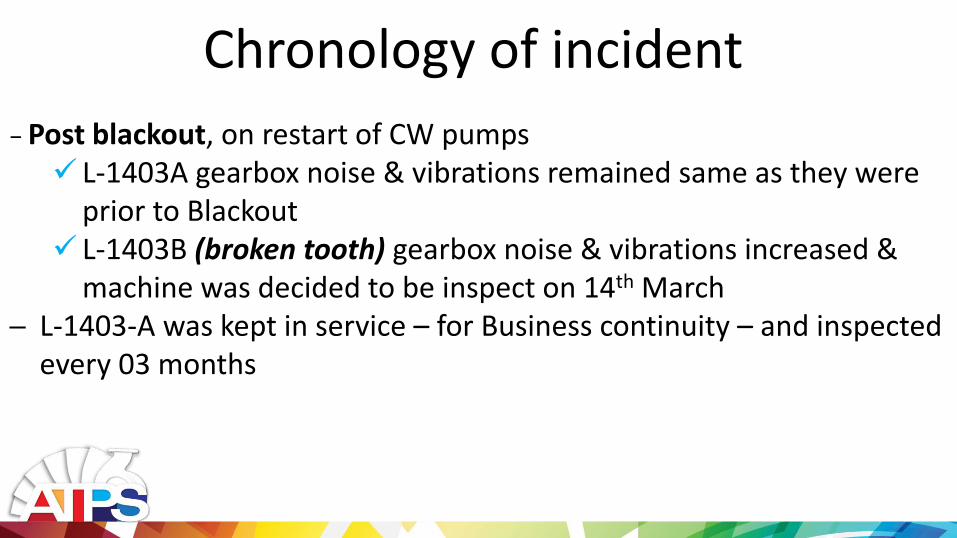
− Post blackout, on restart of CW pumps L-1403A gearbox noise & vibrations remained same as they were
prior to Blackout L-1403B (broken tooth) gearbox noise & vibrations increased &
machine was decided to be inspect on 14th March ─ L-1403-A was kept in service – for Business continuity – and inspected
every 03 months
Chronology of incident

CSI Trends
Typical trend of Broken tooth-Fish Tail wave forms

Observation and Wear Pattern
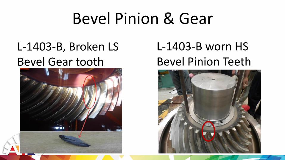
Bevel Pinion & Gear
L-1403-B, Broken LS Bevel Gear tooth
L-1403-B worn HS Bevel Pinion Teeth
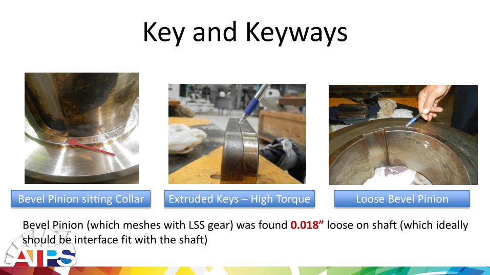
Key and Keyways
Bevel Pinion (which meshes with LSS gear) was found 0.018” loose on shaft (which ideally should be interface fit with the shaft)
Extruded Keys – High Torque Loose Bevel Pinion Bevel Pinion sitting Collar

Bevel Pinions Wear
L-1403-B L-1403-A
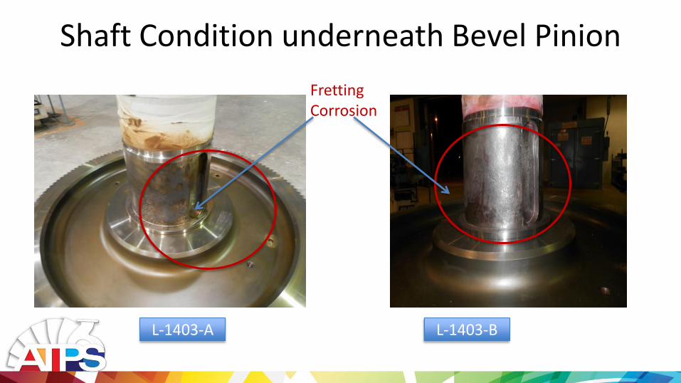
Shaft Condition underneath Bevel Pinion
L-1403-B L-1403-A
Fretting Corrosion

Other Observations
• All Bearings – Normal
• Clearances in Bearings – Within Range
• Anti-Rotation Device – Normal
• Roller Bearings - Normal
• Casing Internals - Normal
Root Cause Analysis

RCA-Fretting Corrosion
• One of the critical observation taken during the removal of HS Bevel Pinion was the evidence of fretting in the Hub of Bevel gear and Shaft.
• "Fretting is a special wear process that occurs at the contact area between two materials under load and subject to minute relative motion by vibration or some other force." ASM Handbook

• Fretting Corrosion aggravates in • Presence of lubrication • Cyclic loading • High Torque
• All of the above was present in this case. • Case was then taken up with OEM for his review and in
parallel in house repairs were done. • Immediate solution to address this was to increase the Fit.
RCA-Fretting Corrosion
Fretting Corrosion

In-house Repair Methodology • Machining of Internal Diameter of Bevel Pinion to ensure
uniform Diameter • Build-up of Shaft using Electrode E-6010 followed by
PWHT • New Keys and Keyway Machining. Keys to be Snug fit • DPT & MPI of all parts • Increased interference to 0.003” between shaft and
pinion • Smoothening of broken tooth area on Bevel Gear.
Removing material thru pencil grinder and reuse Bevel Gear.

RCA
K.F

Route Waveform
25-May-15 03:16:52
P-P = 1.86
PK(+/-) = 1.41/1.38
CRESTF= 2.15
0 10 20 30 40 50 60
-1.6
-1.2
-0.8
-0.4
0.0
0.4
0.8
1.2
1.6
Time in mSecs
Ac
ce
lera
tio
n i
n G
-s
12 - CW Pump B
14TP-1403B-G3H Shaft 02 Inboard Horizontal
Route Spectrum
25-May-15 03:16:52
OVERALL= 1.06 V-DG
PK = 1.06
LOAD = 100.0
RPM = 5100. (85.00 Hz)
0 100 200 300 400 500
0
0.1
0.2
0.3
0.4
0.5
0.6
0.7
0.8
Frequency in Orders
PK
Ve
loc
ity
in
mm
/Se
c
1.7
02
.90
3.7
44
.64
6.0
27
.94
10
.17
11
.44
12
.03
18
.02
20
.37
27
.48
Route Waveform
03-Jun-15 15:53:15
P-P = 1.79
PK(+/-) = 1.63/1.33
CRESTF= 2.57
0 10 20 30 40 50 60
-1.5
-1.0
-0.5
0
0.5
1.0
1.5
2.0
Time in mSecs
Ac
ce
lera
tio
n i
n G
-s
12 - CW Pump B
14TP-1403B-G4H Shaft 02 Outboard Horizontal
Route Spectrum
03-Jun-15 15:53:15
OVERALL= .8532 V-DG
PK = .8493
LOAD = 100.0
RPM = 5100. (85.00 Hz)
0 100 200 300 400 500
0
0.1
0.2
0.3
0.4
0.5
0.6
0.7
Frequency in Orders
PK
Ve
loc
ity
in
mm
/Se
c
1.6
42
.85
4.0
14
.37
6.0
51
0.2
61
2.0
51
8.1
32
0.5
02
7.6
63
4.7
6
55
.31
Analysis: • The maximum vibration recorded post startup was less than 1 mm/sec RMS
value. With PK-PK value of about 1.8 mm/sec. • No impacting in waveforms
Pot Repair startup

Conclusion and Lesson Learnt

Conclusion • Loose pinion on shaft had resulted in repeated cyclic loading on the LS
gear which eventually generated the high stress points on gear teeth
• During Startups, the initial torque on gears are normally high, therefore post black out, upon TP-1403B startup the high stressed portion on a LS gear teeth had given away, resulting in high noise & vibration
• Bevel gear pinion interference with the shaft was not adequate (which is a design Work-man ship related flaw). That further aggravates during the course of time & eventually resulted in failure.

• OEM latter accepted the fault and increased tolerance from 270 H7/n5(transition fit) to 270 H7 270 r6 shaft leads to a min interference of 0.0018” and a max of 0.005”. It was hence a design error.
• The gear set has been running from 03 years with no increase in
vibration level and within acceptable noise levels
Conclusion

Lessons Learnt • Fit Type to be given due consideration during design phase
• FAT to be carried out to asses design considerations
• No reliance on Accelerometer
• Proper Vibration Monitoring Regime Development
• Use of Sound meter for Noise Monitoring
• Oil analysis for metallic particle through a Gear Box Return Oil drain to be made part of routine monitoring
Recommended