1 TD26_CC_SiC
06-September-2011
Assembly procedure of TD26_CC_SiCF. Rossi

2 TD26_CC_SiC
INTRODUCTION
ACCELERATING STRUCTURE PETS
Vacuum flange
Manifold
RF flange and waveguide
Wakefield monitor
Cooling circuit
Interconnection bellow
AS
Damping load
500 mm
220 mm
REQUIREMENTS
• COAXILITY ERROR: < 10 µm
• ALIGNMENT ERROR BETWEEN MANIFOLDS AND DISKS STACK: ±10 µm
ON-OFF mechanism
Vacuum flange
RF flange
Coupler
Cooling circuit
Octant with damping material
FrictionalcontactFrictional
contactEBW EBW
EBW EBW
REQUIREMENTS
• COAXILITY ERROR: < 25 µm

3 TD26_CC_SiC
INTRODUCTION
Main technologies involved in the assembly procedure:
Bonding (atmosphere: H2, temperature: ~1000 °C)
Brazing (atmosphere: H2 or vacuum, temperature: ~1000 °C, brazing alloy: AuCu or AgCu)
EBW
(Laser welding)
4 TD26_CC_SiC
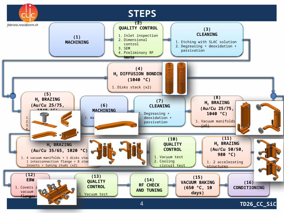
STEPS
(1)MACHINING
(3)CLEANING
1. Etching with SLAC solution2. Degreasing + deoxidation + passivation
(4)H2 DIFFUSION BONDING
(1040 °C)
1. Disks stack (x2)
(2)QUALITY CONTROL
1. Inlet inspection2. Dimensional control3. SEM4. Preliminary RF tests
(5)H2 BRAZING
(Au/Cu 25/75, 1040 °C)
1. Manifold cover (x2)2. WFM (x4)3. Waveguides (x8)4. Cooling system (x8)
(6)MACHINING
1. Waveguides (x8)
(7)CLEANING
1. Degreasing + deoxidation + passivation
(8)H2 BRAZING
(Au/Cu 25/75, 1040 °C)
1. Vacuum manifolds (x6)
(9)H2 BRAZING
(Au/Cu 35/65, 1020 °C)
1. 4 vacuum manifolds + 1 disks stack + 1 interconnection flange + 8 steel inserts + tuning studs (x2)
(11)H2 BRAZING
(Au/Cu 50/50, 980 °C)
1. 2 accelerating structures
(15)VACUUM BAKING(650 °C, 10 days)
(14)RF CHECK AND
TUNING
(16)CONDITIONING
(10)QUALITY CONTROL
1. Vacuum test2. Cooling circuit test
(12)EBW
1. Covers and vacuum flanges
(13)QUALITY CONTROL
1. Vacuum test

5 TD26_CC_SiC
WORKFLOW: AS 1
5. H2 brazing(AuCu 25/75,
1040 °C)
8. H2 brazing(AuCu 25/75,
1040 °C)
6. Machining
7. Cleaning
10. QC
4. H2 bonding(1040 °C)
9. H2 brazing(AuCu 35/65,
1020 °C)
Disks stack
Waveguide WaveguideManifold WFM Manifold Manifold cover
1. Vacuum test2. Cooling circuit test

6 TD26_CC_SiC
WORKFLOW: AS 2
5. H2 brazing(AuCu 25/75,
1040 °C)
6. Machining
7. Cleaning
4. H2 bonding(1040 °C)
Disks stack
Waveguide WaveguideManifold Manifold Manifold cover
8. H2 brazing(AuCu 25/75,
1040 °C)
10. QC
9. H2 brazing(AuCu 35/65,
1020 °C)
1. Vacuum test2. Cooling circuit test

7 TD26_CC_SiC
WORKFLOW
12. EBW
11. H2 brazing(AuCu 50/50,
980 °C)
13. QC 1. Vacuum test
8 TD26_CC_SiC
ASSEMBLY PROCEDURE
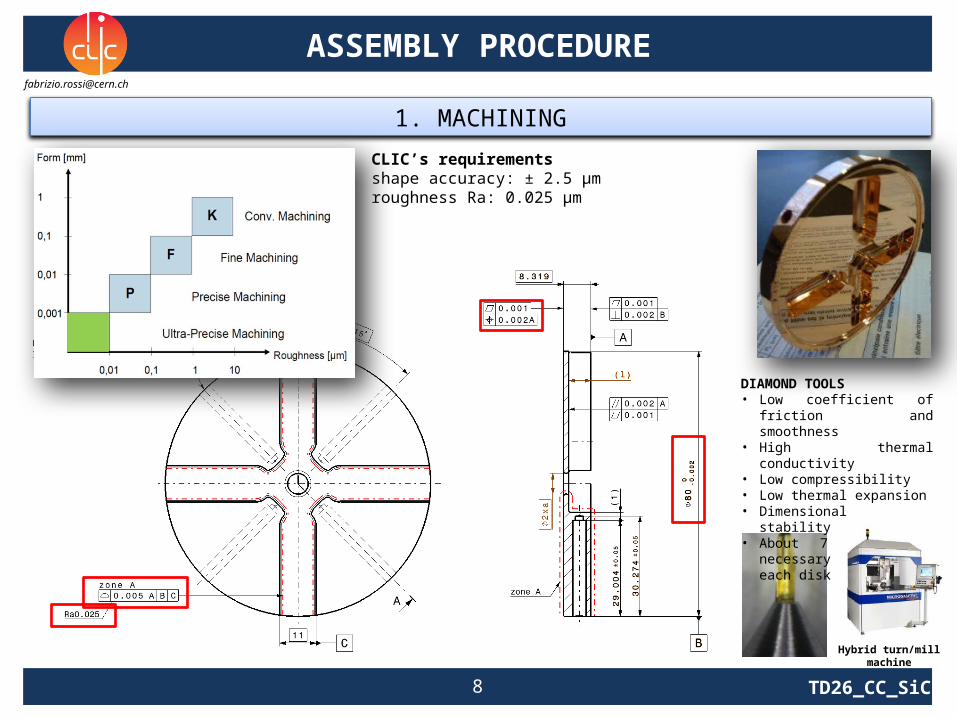
CLIC’s requirements shape accuracy: ± 2.5 µmroughness Ra: 0.025 µm
1. MACHINING
DIAMOND TOOLS• Low coefficient of friction and
smoothness• High thermal conductivity• Low compressibility• Low thermal expansion• Dimensional stability• About 7 tools are necessary to
machine each disk
Hybrid turn/mill machine

9 TD26_CC_SiC
ASSEMBLY PROCEDURE
2. QUALITY CONTROL
• The inspection takes place in specific room, with all the important issues (clean air, gloves, shoes with gloves, specific glasses and specific machines), in order to check the surface for scratches, dents, pits, cracks. The pieces are also organized in photo archives.
• If parts are not clean enough, cleaning procedure should be done again. If parts are not clean, measurement can’t be done because any oil or dust could have an influence on measurement machines.
Inlet inspection
Dimensional control
CERN workshop metrology laboratory• Class 1 according to VDE/VDI 2627 standard
• Reference temperature: 20 °C• Temperature gradients: 0.2 K/hour, 0.4 K/day, 0.1 K/meter
• Conditioner with high accuracy of temperature and humidity control (± 0.5 K)• Filters needed to prevent dust in the dimensional control room
• Vibrations control
SEM analysis
• Identify the machining quality (machining marks, burrs) and the general surface quality (contaminations, handling marks, faceting) before operation at high power.
• Characterize the surface (craters, smoothening, waves, peaks, projections, oxidation).
New Leitz PMM-C Infinity• Dimensional control of disks• Accuracy: ±(0.3 + L/1000) μm• Pieces up to 1.2 m• Probe head has adjustable force (0.02-0.26 N)
VEECO• Roughness and flatness measurements• Uses white light, lens and CCD camera
• Two hours to measure 80 mm disk and two hours to process the images
10 TD26_CC_SiC
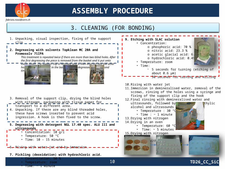
9. Etching with SLAC solution• Concentration:
o phosphoric acid: 70 %o nitric acid: 23.3 %o acetic glacial acid: 6.6 %o hydrochloric acid: 0.49 %
• Temperature: room• Time:
- 5 seconds for turning (etching of about 0.6 µm)- 30 seconds for turning and milling
10. Rising with water jet11. Immersion in demineralised water, removal of the screws, rinsing of the
holes using a syringe and fixing of the support clip and the hook12. Final rinsing with demineralised water and ultrasounds, followed by
rinsing with ethylic alcohol and ultrasounds• Temperature : 30 °C• Time : ~ 1 minute
13. Drying with nitrogen14. Drying in an oven
• Temperature: 60 °C• Time: ~ 5 minutes
15. Drying with nitrogen 16. Packaging with tissue paper
ASSEMBLY PROCEDURE
3. CLEANING (FOR BONDING)
1. Unpacking, visual inspection, fixing of the support clip
2. Degreasing with solvents Topklean MC 20A and Promosolv 71IPAThis treatment is repeated twice if there are more than two blind holes. After the first degreasing the piece is removed from the basket and it put onto tissue paper. The support clip is removed and is then inserted into the other holes. The disk is placed in the basket and is degreased for the second time.
3. Removal of the support clip, drying the blind holes with nitrogen, packaging with tissue paper for transport to a different area.
4. Unpacking. If there are any blind threaded holes, these have screws inserted to prevent acid ingression. A hook is then fixed to the screw.
5. Degreasing with detergent NGL 17.40 spec. ALU III and ultrasounds
• Concentration: 10 g/l• Temperature: 50 °C• Time: 10 – 15 minutes
6. Rising with water jet and by immersion.
7. Pickling (deoxidation) with hydrochloric acid.• Concentration: 50 %• Temperature: room• Time: ~ 1 minute
8. Rising with water jet and by immersion.

11 TD26_CC_SiC
ASSEMBLY PROCEDURE
4. H2 DIFFUSION BONDING (1040 °C)
PRE-ASSEMBLY
STRAIGTHNESS MEASUREMENTS
• Once the assembly procedure is completed, straightness measurements are performed using the Mitutoyo Linear Height LH-600.
• The measurements are done with the accelerating structure on the V-support and considering two reference lines, called REF A and REF B.
• The measurement is done before and after transport to the oven and they are organized in charts.
• Accuracy of V-shape column: ± 1.5 µm
REF A REF BMitutoyo Linear Height LH-600Measuring range: 0-972 mm Resolution: 0.1 µmAccuracy: (1.1+0.6L[mm]/600) µmMeasuring force: 1N

12 TD26_CC_SiC
ASSEMBLY PROCEDURE
4. H2 DIFFUSION BONDING (1040 °C)
TRANSPORT TO FURNACE
1. Load (0.28 MPa) is applied to the disks stack using the load device and thermocouples are mounted to measure the temperature history during the heat treatment .
3. Bonded disks stack 4. Particular of the grains aspect after the heat treatment. Grains size order of few millimeters.
2. Bonding inside the furnace:• atmosphere: H2
• temperature: 1040 °C
Before each bonding cycle, a outgassing cycle is performed.
LOAD APPLICATION
13 TD26_CC_SiC
ASSEMBLY PROCEDURE
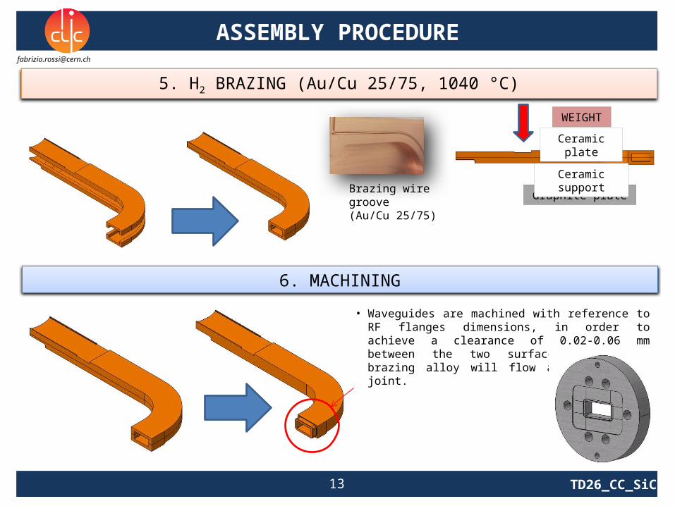
5. H2 BRAZING (Au/Cu 25/75, 1040 °C)
6. MACHINING
• Waveguides are machined with reference to RF flanges dimensions, in order to achieve a clearance of 0.02-0.06 mm between the two surfaces where the brazing alloy will flow and create the joint.
Graphite plate
Ceramic support
Ceramic plate
WEIGHT
Brazing wire groove(Au/Cu 25/75)

14 TD26_CC_SiC
ASSEMBLY PROCEDURE
9. H2 BRAZING (Au/Cu 35/65, 1020 °C)
Rod
Nut
Lower plate
Lateral support
Lateral spring
Lateral plate
Upper support
Upper spring
Wedges
• Upper spring (graphite): apply a vertical force on the manifolds through the upper support and allow thermal expansion of the assembly during the brazing cycle.
• Rod (stainless steel): connect upper support and lower plate.• Lower plate (graphite): support the assembly during alignment operations and brazing cycle.• Wedges (ceramic): allow small adjustment of manifolds in the vertical direction.• Lateral springs (graphite): apply an horizontal force to the manifolds through the lateral
plates and allow thermal expansion of the assembly during the brazing cycle.• Lateral supports (stainless steel): support the springs.

15 TD26_CC_SiC
ASSEMBLY PROCEDURE
10. H2 BRAZING (Au/Cu 50/50, 980 °C)
Ceramic
Inox plate
Ceramic
Inox plate
3 DOF
1st structure 2nd structure and measurement
Auxiliary frame Alignment Tooling ready for transport to furnace
TOOLING
Mitutoyo Linear Height LH-600

16 TD26_CC_SiC
ASSEMBLY PROCEDURE
12. EBW
Cover
Small cover
Vacuum flange
EBW machine(CERN workshop)
EBW machine chunk
TOOLING

17 TD26_CC_SiC
ASSEMBLY PROCEDURE
13. QUALITY CONTROL
Vacuum test
14. RF CHECK AND TUNING
• After bonding and brazing processes, accelerating structures must be tuned to compensate the different assembly errors.
• Tuning is performed modifying by plastic deformation the cell walls and checking, at the same time, the results of this operation by means of a network analyser.
• Plastic deformation is achieved by pushing or pull the tuning studs brazed in the accelerating structure. 0.05
0.1
0.15
30
210
60
240
90
270
120
300
150
330
180 0
• Leak detector and Helium are used for vacuum tests.
• Helium is pumped around the accelereting structure and if a leak is present is detected by the machine.

18 TD26_CC_SiC
ASSEMBLY PROCEDURE
15. VACUUM BAKING (650 °C, 10 days)
16. CONDITIONING
Muffle
Accelerating structure
Tooling
• The accelerating structure is positioned inside a container with a protective atmosphere (N2) to prevent copper oxidation.
acel Serial vb732 on Station 4 on 10-JUN-08
1.00E-10
1.00E-09
1.00E-08
1.00E-07
1.00E-06
1.00E-05
1.00E-04
0.75 1.75 2.80 3.73 4.76 5.81 6.85 7.89 8.93 9.97 11.01 12.06 13.10 14.14 15.18 16.22 17.26 18.23 19.27
Days on Station
To
rr
tubePres
acel Serial vb732 on Station 4 on 10-JUN-08
0
100
200
300
400
500
600
700
0.75 1.75 2.80 3.73 4.76 5.81 6.85 7.89 8.93 9.97 11.01 12.06 13.10 14.14 15.18 16.22 17.26 18.23 19.27
Days on Station
Deg
re
es
C
Avg.Temp
19 TD26_CC_SiC
CONCLUSIONS
• Requirements for disks machining are very strict (shape accuracy: ± 2.5 µm, roughness Ra: 0.025 µm)
• These requirements should be preserved after each step of the assembly procedure
• Toolings are necessary to fulfill these accuracy needs during the different steps
• Nevertheless, assembly errors are present at the end and the final RF tuning of the accelerating structure is performed to compensate them.
Main critical issues:
- Alignment of manifolds and AS for brazing
- Residual deformations after heat treatments at ~ 1000 °C

20 TD26_CC_SiC
PROPOSALS
Mectalent
• Manufacturing of toolings for brazing and EBW. For what regards brazing, a close collaboration with Loval is required.
• Timetable: April 2012.
Loval
• Furnaces will be adapted to perform H2 brazing at 25 mbar. In the meantime, brazing tests can be done for those components for which H2 atmosphere is not mandatory (like cooling circuits, waveguides, WFM).
• Timetable: mid of 2012

21 TD26_CC_SiC
THANKS
G. Riddone
A. Samoshkin (Engineering design)
P. Piirainen (Engineering design)
A. Solodko (Engineering design)
S. Lebet (Assembly and brazing)
S. Atieh (Machining)
A. Olyunin (Quality control)
M. Malabaila (Cleaning)
J. Shi (RF check and tuning)
Recommended