11/20/2017
1
EVE 402 Air Pollution Generation and Control
Chapter #5 Lectures (Part 6)
Fabric Filtration
• One of the oldest and most widely-used methods for separating particles from a gas stream
• Particle-laden gas flows through a number of filter bags, leaving the particles retained on the fabric
• Constructed of any material compatible with gas and particulate
• May be cleanable or non-cleanable (discarded after use)
Typical Dimensions Dirty gas flows into page
Fabric material may be woven, felted, or knitted

11/20/2017
2
Woven Fabric
• Particles deposit on surface of fabric
• Woven fabric has lower collection efficiency
• Dust layer presents a significant surface for collection
Felt Fabric
• Surface of felt supports dust cake
• Used in pulse jet filters
The Pros and Cons • Pros
– High collection efficiency even for small particles – Can operate on a wide variety of dust types – Wide choices of filters depending on application – Simultaneous removal of particles and some gases – Modular in design (simplifies maintenance) – Can operate over an extremely wide range of volumetric flow
rates (100 – 5x106 ft3/m) – Requires reasonably low pressure drop – Lower capital cost than an electrostatic precipitator (ESP)
• Cons – Requires large foot print – Fabric can be harmed by high temperatures or corrosive gases – Inappropriate for moist environments – Potential for fire or explosion from static charge – Higher annual cost than an ESP – Higher pressure drop compared to an ESP
11/20/2017
3
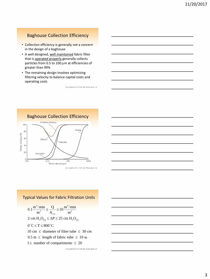
Baghouse Collection Efficiency
• Collection efficiency is generally not a concern in the design of a baghouse
• A well designed, well maintained fabric filter that is operated properly generally collects particles from 0.5 to 100 mm at efficiencies of greater than 99%
• The remaining design involves optimizing filtering velocity to balance capital costs and operating costs
Baghouse Collection Efficiency
Typical Values for Fabric Filtration Units
3 3
2 2
x-s
2 2l l
m min Q m min0.1 10
m A m
2 cm H O 25 cm H O
0 C T 800 C
10 cm diameter of filter tube 30 cm
0.5 m length of fabric tube 10 cm
1 number of compartments 20
P
m

11/20/2017
4
Baghouses are named according to how the dirty bags are cleaned:
• Reverse-air
• Shaker
• Pulse-jet
• Cartridge filter designs
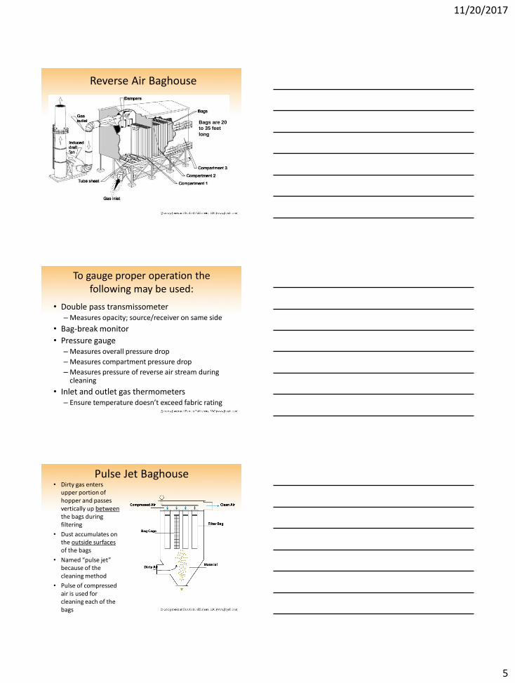
Reverse Air Baghouse • Uses compartmentalized
designs
• Named “reverse air” from the cleaning method
• During cleaning the gas flow through a compartment is stopped, and filtered gas is passed in a reverse direction through the bags
• Bags are hung from top of compartments
• Bags attached by springs on top
Reverse Air Baghouse
• Bottoms of bags are attached to a plate called tube sheet mounted right above the hopper
• Dirty air enters the inside of each reverse air bag
• The dust cake accumulates on the interior surfaces of the bags
• The dust cake causes most of the filtration
Dust cake
Air flow inlet
Tube sheet
11/20/2017
5
Reverse Air Baghouse
Bags are 20
to 35 feet
long
To gauge proper operation the following may be used:
• Double pass transmissometer – Measures opacity; source/receiver on same side
• Bag-break monitor
• Pressure gauge – Measures overall pressure drop
– Measures compartment pressure drop
– Measures pressure of reverse air stream during cleaning
• Inlet and outlet gas thermometers – Ensure temperature doesn’t exceed fabric rating
Pulse Jet Baghouse • Dirty gas enters
upper portion of hopper and passes vertically up between the bags during filtering
• Dust accumulates on the outside surfaces of the bags
• Named “pulse jet” because of the cleaning method
• Pulse of compressed air is used for cleaning each of the bags

11/20/2017
6
Pulse Jet Bags
• Cleaned air enters the cylindrical bags and moves upward into the clean gas plenum at the top of the baghouse
• The outlet duct from the plenum takes the cleaned air to the fan and out to the stack
Dirty Air Flow
Treated Air Outlet Treated Air Outlet
Particles collect
Pulse Jet Baghouse
Looking up into an array of bags in a Pulse Jet Baghouse

11/20/2017
7
Pulse Jet Baghouse • Bags are cleaned by
introducing a high-pressure pulse of compressed air at the top of each bag
• Pulse generates a pressure wave that travels down inside the bag
• This cracks the dust cake on the outside of the bags and causes some of the dust to fall into the hopper
• Cleaning is done row by row while baghouse is operating
Shaker Baghouses
• Shaking bag in a simple harmonic or sinusoidal motion on the order of a few inches
• Every 30 sec to few minutes
Bags and Support Structure
Midwesco, Inc. Bagsandcages.com

11/20/2017
8
With pulse-jet cleaning, no bags have to be taken out of service (astecinc.com)
Aget Dust Collection Bag House $800 Model # FT-40 33" x 51" x 120" tall bag house 40 @ 5" dia. x 88" long bags 13" dia. air intake 240v or 460v 3 ph. shaker motor 37" x 58" x 72" welded steel stand No blower or cyclone
Baghouse cage 4.5” x 48” $60.00
Filter Characteristics
• Filter medium serves as a structural support rather than impaction surface
• Packing Density
fiber volume1 porosity
total volume
For fiber filter, 0.1
For woven filter, ~ 0.3
Filter Materials
• Woven fabric – Interlaced yarn type
• Felted fabric – Randomly oriented fibers
• Membranes – PTFE laminated to a woven fabric or felt
• Sintered metal fibers – Small metal fibers randomly oriented on a cylinder
• Ceramic cartridges – Fabricated on honeycomb or cylinder

11/20/2017
9
Filter Materials
PTFE laminated
Ceramic
Sintered metal
Material Characteristics
Stop
Pressure Drops • Pressure drop across the baghouse is given as
• The flow through the filter and cake layer is assumed to be viscous (i.e., mg is important)
– Thus ΔP may be represented by Darcy’s equation:
∆P = ∆PF + ∆PC + ∆PS Eq. 5 − 89, p. 253
where: ∆PF = pressure drop across fabric
∆PC = pressure drop across particle or cake layer
∆PS = pressure drop across the structure (negligible)
0
∆P = ∆PF + ∆PC =μgxFV
KF+
μgxCV
KC

11/20/2017
10
Pressure Drops (2)
where mg = gas viscosity xF, xC = filter and cake layer thicknesses, respectively KF, KC = filter and cake layer permeabilities, respectively V = superficial filtering velocity (air-to-cloth ratio)
∆P = ∆PF + ∆PC =μgxFV
KF+
μgxCV
KC
Air-to-Cloth Ratio
3
2
volumetric gas flow rate, m min
cloth area, m
QV
A
Q
A
Superficial filtration velocity (average velocity) also known as the air-to-cloth ratio
Baghouse Cleaning Method Air-to-Cloth Ratio
Shaking 2 – 6 (ft3/min)/ft2
Reverse air 1 – 3 (ft3/min)/ft2
Pulse jet 5 – 15 (ft3/min)/ft2
Typical Air-to-Cloth Ratios
Dust Cake Growth • Over time, the depth of the dust layer (dust
cake) increases
ic
c
3
i
3
c
c p
C Vtχ Eqn 5-91 , p. 254
ρ
where:
C dust loading, kg m
V filtration velocity, m s
t time of operation, min
ρ bulk density of the particulate layer, kg m
ρ ρ c
c = packing density

11/20/2017
11
Pressure Drop
3
1 2 i i
i
1 2
1 2
Pressure drop through the baghouse
ΔP K V K C Vt V C dust loading, kg/m
Areal Dust Density W = C Vt
Filter drag
ΔPS S=K + K W in Pa-min/m
V
K and K to be determined empirically (resistan
R c sP P P P
R
c
s
ce factor)
ΔP fabric pressure drop
ΔP = particle cake layer pressure drop
ΔP structure pressure drop
Typical filter drag, S, vs. areal dust density curves for various degrees of cleaning
K1
K2
‘
‘
Variation of ΔP with Time tf = N(tr+tc)-tc
where, tf = filtration time (the elapsed time a compartment runs between cleanings) tr = run time (the time elapsed between cleanings of any two compartments) tc = cleaning time (the time required to clean one compartment) N = total number of compartments When one compartment is taken
offline for cleaning, all gas flows through the remaining compartments. So, ΔP increases suddenly.
Just as ΔP reaches its max, the cleaned compartment is returned to service and ΔP decreases suddenly.
11/20/2017
12
Applications • A baghouse for a 250 MW utility boiler may have 5,000
separate bags with a total fabric area approaching 500,000 square feet
• Most cement plants have between 40 and 80 separate fabric filter control systems ranging in size from 30 actual cubic meters per minute capacity to more than 100,000 actual cubic meters per minute capacity
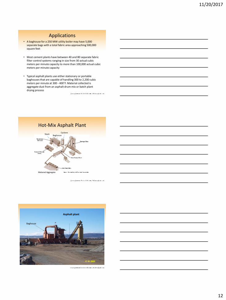
• Typical asphalt plants use either stationary or portable baghouses that are capable of handling 300 to 2,200 cubic meters per minute at 300 - 400˚F. Material collected is aggregate dust from an asphalt drum mix or batch plant drying process
Hot-Mix Asphalt Plant
Metered Aggregate
Cyclone Baghouse
Stack
Asphalt plant
Baghouse

11/20/2017
13
Asphalt Plant
Asphalt drum
Baghouse
Baghouse
Asphalt Plant
Inlet to baghouse
Pulse jet baghouse
Asphalt Plant
Cyclone
Flow
baghouse
11/20/2017
14
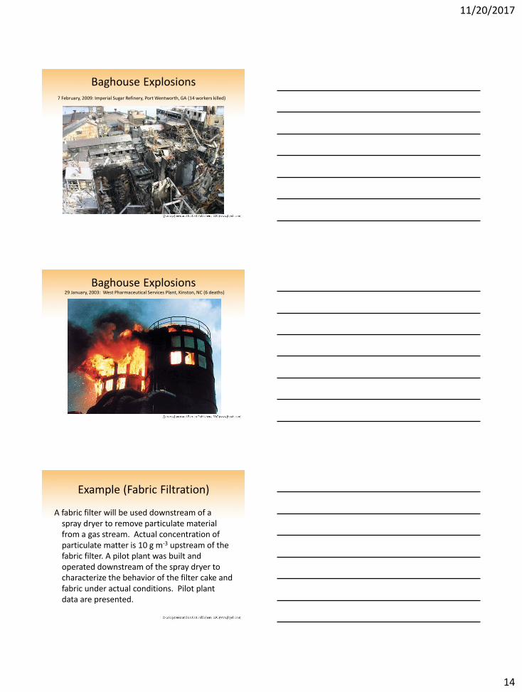
Baghouse Explosions 7 February, 2009: Imperial Sugar Refinery, Port Wentworth, GA (14 workers killed)
Baghouse Explosions 29 January, 2003: West Pharmaceutical Services Plant, Kinston, NC (6 deaths)
Example (Fabric Filtration)
A fabric filter will be used downstream of a spray dryer to remove particulate material from a gas stream. Actual concentration of particulate matter is 10 g m-3 upstream of the fabric filter. A pilot plant was built and operated downstream of the spray dryer to characterize the behavior of the filter cake and fabric under actual conditions. Pilot plant data are presented.

11/20/2017
15
Filter Drag (s) [cm H2O(l) cm-1 sec]
Areal Dust Loading (w) [g m-2]
8.0 0.0
13.2 0.5
15.3 1.0
16.8 1.5
18.3 2.0
19.9 2.5
21.4 3.0
22.9 3.5
24.5 4.0
a. Determine the value of the effective residual filter drag (K1) with units of cm H20(l) cm-1 sec. b. Determine the value of the filter cake resistance factor (K2) with units of ((cm H2O(l)/(cm/sec))/(g/m2).
Recommended