32
www.basor.comEU DECLARATION OF CONFORMITY
DECLARACIÓN UE DE CONFORMIDAD
The company / La Empresa:
BASOR ELECTRIC, S.A.
Address / Dirección:
Av. Alcodar, 45-47, 46700. Gandía (VLC), Spain.
Declares that the product:
Declara que el producto:BASORFIL BFR
Installed in accordance to the installa! on standards, manufacturer’s instruc! ons and professional rules, duly maintained and used for the applica! ons as intended.
Instalado de acuerdo con las normas de instalación, instrucciones del fabricante y conforme a las reglas profesionales, debidamente mantenido y u! lizado en las aplicaciones para las que está previsto.
Complies with the essen! al requirements of the Council Direc! ves:
Cumple con los requisitos esenciales de las Direc! vas del Consejo:2014/35/UE (Low Voltage Direc! ve) / (Direc� va de Baja Tensión)
Incorporated in the Spanish Legisla! on in: R.D. 7/1988 and its modifi ca! on R.D. 154/1995.
Incorporado en la Legislación Española en: R.D. 7/1988 y su modifi cación R.D. 154/1995.
And it is suitable and safe for the intended use and it is in conformity with the following standard:
Es adecuado y seguro para el uso a que está des! nado y es conforme con la siguiente norma:UNE EN 61537
Addi! onal informa! on:
Información adicional:
This product is intended to be installed and maintained by skilled persons, it may be used by ordinary persons only as a replacement part, to subs! tute for an iden! cal device.
Este producto está previsto para ser instalado y mantenido por un profesional, puede ser usado por una persona no formada para reemplazamiento de uno idén! co.
Place and date:
Lugar y fecha:
Gandía April 2016
Gandía Abril 2016
Technical department / Departamento Técnico

35
DATA SHEET BASORFIL BFR
UNE-EN 61537 REV.12/02/2018
www.basor.com
ER 50x50+TAPABF/BFR
ASSEMBLING INSTRUCTIONS
Models (BxH):
60x35; 100x35; 150x35; 200x35; 300x35; 60x65; 100x65; 150x65; 200x65; 300x65; 400x65; 500x65; 600x65; 200x105; 300x105; 400x105; 500x105; 600x105.
Materials/Coatings: EZ, HDG.
Characteristics of the cable tray:
- Metallic
- No-fl ame propagating component
- System with electrical continuity
- Electrically conductive component
- Minimum temperature of -50 ˚C
- Maximum temperature of 150 ˚C
- With metallic coating, resistance to corrosion:
EZ coating: class 3
HDG coating: class 7
- Impact strength: 20J
- Comply with RoHS, 2002/95/CE
Base Models Classifi cation
60 Z
100 Y
150 Y
200 Y
300 Y
400 Y
500 Y
600 Y
Classifi cation acc. to the free base area
Accessories:This product family has a wide range of accessories: cover, divider PS, drop out plate BJC.Union acc.: URBF Quick Joint, CGBF Bolt&Staple Set, ULA Set, TBF Bolt Set and MU multiunion plate.Support acc.: SSC, SL, SLS, Universal Box Support SUC, mini Universal Box Support SUCM.
- To assemble 2 trays 1BF bolt&Staple Set are needed in each wing of the tray.
- For trays wider than 200 mm (8”) an additional BF Bolt&Staple Set is needed in the center of the base.
- Models of 65 mm (2”) and 105 mm (4”) in height could use one Quick Joint BF 65/105 (or ULA Set) in each wing of the tray instead of BF bolt&staple set.
- Tray installation for an electrical system should NOT run under other types of canalisations such as water, vapour or gas.
- To guarantee a good ventilation we recommend installing the trays keeping a minimum distance of 250 mm (10”) between each tray.
- Trays which are placed on supports shall have to keep a gap of 20 mm (4/5”) from the wall to allow for a proper ventilation of the cables.
- Is recommended to install the union joints between L/4 to L/5 of the distance between supports.
This technical data sheet issued accordingly to the fulfi llment of the product Standard, is itself a necessary analyses of the electric risks according to the low tension Directive 2014/35/UE of February 26th 2014, in eff ect from April 20th 2016

36
SAFE WORKING LOAD
5
10
15
20
25
30
35
40
45
50
55
CTA BFR B=500..600
CTA BF B=500..600
CTA BFR B=100..400
CTA BF B=100..400
Def
CTA
(K
g/m
)
10
20
30
40
50
60
70
80
90
100
110
Def (m
m)
d (m)
1.0 1.1 1.2 1.3 1.4 1.5 1.6 1.7 1.8 1.9 2.0 2.1 2.2 2.3 2.4 2.5
BFR / BF H=65 mm
10
20
30
40
50
60
70
CTA BFR B=400..600
CTA BF B=400..600
CTA BFR B=100..300
CTA BF B=100..300
Def
CTA
(K
g/m
)
20
40
60
80
100
120
140
Def (m
m)
d (m)
1.0 1.1 1.2 1.3 1.4 1.5 1.6 1.7 1.8 1.9 2.0 2.1 2.2 2.3 2.4 2.5
BFR / BF H=105 mm
1,0 1,1 1,2 1,3 1,4 1,5 1,6 1,7 1,8 1,9 2,0
0
5
10
15
20
25
30
CTA BFR
CTA BF
Def
d (m)
CT
A (
Kg
/m)
BFR / BF 60x65
0
5
10
15
20
25
30
De
f (m
m)
10
15
20
25
30
35
40
CTA BFR
CTA BF
Def
CTA
(K
g/m
)
10
15
20
25
30
35
40
De
f (m
m)
d (m)
1.0 1.1 1.2 1.3 1.4 1.5 1.6 1.7 1.8 1.9 2.0
BFR / BF H=35 mm
8
www.basor.comEU DECLARATION OF CONFORMITY
DECLARACIÓN UE DE CONFORMIDAD
The company / La Empresa:
BASOR ELECTRIC, S.A.
Address / Dirección:
Av. Alcodar, 45-47, 46700. Gandía (VLC), Spain.
Declares that the product:
Declara que el producto:BASORFIL BF2R
Installed in accordance to the installa! on standards, manufacturer’s instruc! ons and professional rules, duly maintained and used for the applica! ons as intended.
Instalado de acuerdo con las normas de instalación, instrucciones del fabricante y conforme a las reglas profesionales, debidamente mantenido y u! lizado en las aplicaciones para las que está previsto.
Complies with the essen! al requirements of the Council Direc! ves:
Cumple con los requisitos esenciales de las Direc! vas del Consejo:2014/35/UE (Low Voltage Direc! ve) / (Direc� va de Baja Tensión)
Incorporated in the Spanish Legisla! on in: R.D. 7/1988 and its modifi ca! on R.D. 154/1995.
Incorporado en la Legislación Española en: R.D. 7/1988 y su modifi cación R.D. 154/1995.
And it is suitable and safe for the intended use and it is in conformity with the following standard:
Es adecuado y seguro para el uso a que está des! nado y es conforme con la siguiente norma:UNE EN 61537
Addi! onal informa! on:
Información adicional:
This product is intended to be installed and maintained by skilled persons, it may be used by ordinary persons only as a replacement part, to subs! tute for an iden! cal device.
Este producto está previsto para ser instalado y mantenido por un profesional, puede ser usado por una persona no formada para reemplazamiento de uno idén! co.
Place and date:
Lugar y fecha:
Gandía April 2016
Gandía Abril 2016
Technical department / Departamento Técnico

18
DATA SHEET BASORFIL BF2R EZ1000
UNE-EN 61537REV.12/02/2018
www.basor.com
ER 50x50+TAPABF2R EZ1000
ASSEMBLING INSTRUCTIONS
SAFE WORKING LOAD
Models (BxH):
60x65; 100x65; 150x65; 200x65; 300x65; 400x65; 500x65; 600x65; 100x105; 150x105; 200x105; 300x105; 400x105; 500x105; 600x105.
Finishes: EZ1000
Characteristics of the cable tray
- Metallic
- Non-fl ame propagating component
- System with electrical continuity
- Electrically conductive component
- Minimum temperature of -50 ˚C
- Maximum temperature of 150 ˚C
- With metallic coating, resistance to corrosion:
EZ1000 coating: Class 8+
(>1000 hours salt spray test EN-ISO 9227)
- Impact strength: 20J
- Comply with RoHS, 2011/65/UE
Models Clasifi cation
60 Z
100 Y
150 Y
200 Y
300 Y
400 Y
500 Y
600 Y
Classifi cation acc. to the free base area:
1,0 1,5 2,0 2,5
0
5
10
15
20
25
30
35
CTA
Def
d (m)
CT
A (
kg/m
)
BF2R 60x65
0
5
10
15
20
25
30
35
Def (m
m)
- BASORFIL BF2R cable trays don’t need additional elements for the assembly. Each straight element include the union joints. To mount the trays place the cable tray with the union joints over the last tray end and apply pressure as shown in the picture.
- Installing an electrical conduit trays should not be performed under other pipelines such as water, steam, gas.
- To facilitate proper ventilation, we recommend installing the trays with a minimum distance between them of 250 mm.
- Must be separated from the wall 20 mm trays that are placed on supports, to allow optimum ventilation of the cables.
- Is recommended to install the union joints between L/4 to L/5 of the distance between supports.
Accesories:The family has a large range of accessories: Cover TERE/TEBFR, divider profi le PS, drop out plate BJC.Accessories for cut and works on site: Quick joint, bolt and staple set, lateral union set, bf bolt and nut set, multiunion joint.Support accessories: SSC central suspension, SL support, SLS, universal box support SUC, mini universal box support SUCM.
This technical data sheet issued accordingly to the fulfi llment of the product Standard, is itself a necessary analyses of the electric risks according to the low tension Directive 2014/35/UE of February 26th 2014, in eff ect from April 20th 2016

19
SAFE WORKING LOAD
10
15
20
25
30
CTA BF2R B=600
CTA BF2R B=500
CTA BF2R B=400
Def
CTA
(K
g/m
)
30
40
50
60
70
80
90
100
110
120
De
f (mm
)
d (m)
1.0 1.1 1.2 1.3 1.4 1.5 1.6 1.7 1.8 1.9 2.0
BF2R 400..600 H=65 mm
5
10
15
20
25CTA BF2R 300x105
CTA BF2R 200x105
CTA BF2R 100..150x105
Def
CTA
(K
g/m
)
20
30
40
50
60
70
80
90
100
110
De
f (mm
)
d (m)
1.0 1.1 1.2 1.3 1.4 1.5 1.6 1.7 1.8 1.9 2.0
BF2R B=100-300 H=105 mm
10
15
20
CTA BF2R B=600
CTA BF2R B=500
CTA BF2R B=400
Def
CTA
(K
g/m
)
50
60
70
80
90
100
110
120
130
140
150
160
170
180
190
De
f (mm
)
d (m)
1.0 1.1 1.2 1.3 1.4 1.5 1.6 1.7 1.8 1.9 2.0
BF2R B=400-600 H=105 mm
10
15
20
25
30CTA BF2R B=300
CTA BF2R B=200
CTA BF2R B=100..150
Def
CTA
(K
g/m
)
20
25
30
35
40
45
50
55
60
65
70
De
f (mm
)
d (m)
1.0 1.1 1.2 1.3 1.4 1.5 1.6 1.7 1.8 1.9 2.0
BF2R 100..300 H=65 mm
This technical data sheet issued accordingly to the fulfi llment of the product Standard, is itself a necessary analyses of the electric risks according to the low tension Directive 2014/35/UE of February 26th 2014, in eff ect from April 20th 2016

58
DATA SHEET BASORFIL BF2R
NEMA VE1 REV.20/04/2016
www.basor.com
ER 50x50+TAPABF2R
ASSEMBLY INSTRUCTIONS
Models (BxH):
2”x2” (60x65); 4”x2” (100x65); 6”x2” (150x65); 8”x2” (200x65); 12”x2” (300x65); 16”x2” (400x65); 18”x2” (450x65); 20”x2” (500x65); 24”x2” (600x65); 4”x4” (100x105); 8”x4” (200x105); 12”x4” (300x105); 16”x4” (400x105); 18”x4” (450x105); 20”x4” (500x105); 24”x4” (600x105).
Materials/Coatings: EZ, HDG, SS304.
Characteristics of the cable tray:
- Metallic
- No-! ame propagating component
- System with electrical continuity
- Electrically conductive component
- Minimum temperature of -50 ˚C
- Maximum temperature of 150 ˚C
- Impact strength: 20J
- To assemble 2 trays aditional pieces are not needed.
- BF2R wire-mesh cable trays include di" erent # xing points along the base of the tray to ensure a perfect assembly including the widest models.
- Tray installation for an electrical system should NOT run under other types of canalisations such as water, vapour or gas.
- To guarantee a good ventilation we recommend installing the trays keeping a minimum distance of 250 mm (10”) between each tray.
- Trays which are placed on supports shall have to keep a gap of 20 mm (4/5”) from the wall to allow for a proper ventilation of the cables.
- To be used as grounding conductor, models 4”x1”1/2 (100x35), 6”x1”1/2 (150x35), 8”x1”1/2 (200x35), 12”x1”1/2 (300x35), 2”x2” (60x65), 4”x2” (100x65), 6”x2” (150x65), 8”x2” (200x65) must be mounted with ground connection clamp (ref. 2/6796) and 10 AWG wire.
Accessories:Range accessories: Cover, Divider Pro# les, Drop-out plate.Union Elements: Quick Joints (H35&H65-105), BF Bolt&Staple Set, BF Bolt Set, multi-union plate.Supporting elements: SSC, Universal Box Support, Mini Universal Box Support, Conduit Drop-Out Plate.
APPROVALS
- BASORFIL wire-mesh cable trays are UL certi# ed for US and Canada by UL (File - E358301).
- UL certi# cation guarantees that BFR wire-mesh models, mounted following the assembly instructions, can be used as equipment-grounding conductor in accordance with Article 392 of NFPA 70 National Electric Code, and the CEC, Part 1, Canadian Electrical Code.

59
SAFE WORKING LOAD / NEMA CLASSIFICATION
Load Values & NEMA Classi! cation for EZ&HDG
SWL kg/m (lb/ft) Classifi cation
5 ft 8 ft 5 ft 8 ft
1,52 m 2,44 m 1,52 m 2,44 m
BF2R 2”x2” (60x65) 12,5 (8,4) 4,9 (3,3) - -
BF2R 4”x2” (100x65) 28,4 (19,1) 11,1 (7,5) - -
BF2R 6”x2” (150x65) 31,7 (21,3) 12,4 (8,3) - -
BF2R 8”x2” (200x65) 47,6 (32) 18,6 (12,5) 5AA -
BF2R 12”x2” (300x65) 57,1 (38,4) 22,3 (15) 5AA -
BF2R 16”x2” (400x65) 69,9 (47) 27,3 (18,3) 5AA -
BF2R 18”x2” (450x65) 66,7 (44,9) 26,1 (17,5) 5AA -
BF2R 20”x2” (500x65) 63,5 (42,7) 24,8 (16,7) 5AA -
BF2R 24”x2” (600x65) 79,4 (53,3) 31 (20,8) 5A -
BF2R 4”x4” (200x105) 48,0 (32,2) 18,8 (12,6) 5AA -
BF2R 8”x4” (200x105) 72,2 (48,5) 28,2 (18,9) 5AA -
BF2R 12”x4” (300x105) 76 (51,1) 29,7 (20) 5A -
BF2R 16”x4” (400x105) 111,1 (74,7) 43,4 (29,2) 5A 8AA
BF2R 18”x4” (450x105) 109,5 (73,5) 42,8 (28,8) 5A 8AA
BF2R 20”x4” (500x105) 107,8 (72,4) 42,1 (28,3) 5A 8AA
BF2R 24”x4” (600x105) 117,5 (79) 45,9 (30,8) 5A 8AA
Load Values & NEMA Classi! cation for SS304
SWL kg/m (lb/ft) Classifi cation
5 ft 8 ft 5 ft 8 ft
1,52 m 2,44 m 1,52 m 2,44 m
BF2R 2”x2” (60x65) 12,8 (8,6) 5 (3,4) - -
BF2R 4”x2” (100x65) 28,7 (19,3) 11,2 (7,5) - -
BF2R 6”x2” (150x65) 25,3 (17) 9,9 (6,7) - -
BF2R 8”x2” (200x65) 44,5 (29,9) 17,4 (11,7) 5AA -
BF2R 12”x2” (300x65) 54, (36,3) 21,1 (14,2) 5AA -
BF2R 16”x2” (400x65) 60,2 (40,4) 23,5 (15,8) 5AA -
BF2R 18”x2” (450x65) 58,7 (39,4) 22,9 (15,4) 5AA -
BF2R 20”x2” (500x65) 57,1 (38,4) 22,3 (15,0) 5AA -
BF2R 24”x2” (600x65) 54 (36,3) 21,1 (14,2) 5AA -
BF2R 4”x4” (100x105) 51,4 (34,6) 20,1 (13,5) 5AA -
BF2R 8”x4” (200x105) 73 (49) 28,5 (19,2) 5AA -
BF2R 12”x4” (300x105) 69,9 (47) 27,3 (18,3) 5AA -
BF2R 16”x4” (400x105) 76 (51,1) 29,7 (20) 5A -
BF2R 18”x4” (450x105) 74,5 (50,1) 29,1 (19,6) 5A -
BF2R 20”x4” (500x105) 73 (49) 28,5 (19,2) 5AA -
BF2R 24”x4” (600x105) 69,9 (47) 27,3 (18,3) 5AA 8AA
NOTE: Load Values and Classi! cation obtained according to Load to destruction test per NEMA VE1 with 1.5 Safety Factor

32
www.basor.comEU DECLARATION OF CONFORMITY
DECLARACIÓN UE DE CONFORMIDAD
The company / La Empresa:
BASOR ELECTRIC, S.A.
Address / Dirección:
Av. Alcodar, 45-47, 46700. Gandía (VLC), Spain.
Declares that the product:
Declara que el producto:BASORFIL BFR
Installed in accordance to the installa! on standards, manufacturer’s instruc! ons and professional rules, duly maintained and used for the applica! ons as intended.
Instalado de acuerdo con las normas de instalación, instrucciones del fabricante y conforme a las reglas profesionales, debidamente mantenido y u! lizado en las aplicaciones para las que está previsto.
Complies with the essen! al requirements of the Council Direc! ves:
Cumple con los requisitos esenciales de las Direc! vas del Consejo:2014/35/UE (Low Voltage Direc! ve) / (Direc� va de Baja Tensión)
Incorporated in the Spanish Legisla! on in: R.D. 7/1988 and its modifi ca! on R.D. 154/1995.
Incorporado en la Legislación Española en: R.D. 7/1988 y su modifi cación R.D. 154/1995.
And it is suitable and safe for the intended use and it is in conformity with the following standard:
Es adecuado y seguro para el uso a que está des! nado y es conforme con la siguiente norma:UNE EN 61537
Addi! onal informa! on:
Información adicional:
This product is intended to be installed and maintained by skilled persons, it may be used by ordinary persons only as a replacement part, to subs! tute for an iden! cal device.
Este producto está previsto para ser instalado y mantenido por un profesional, puede ser usado por una persona no formada para reemplazamiento de uno idén! co.
Place and date:
Lugar y fecha:
Gandía April 2016
Gandía Abril 2016
Technical department / Departamento Técnico

46
DATA SHEET BASORFIL BFR SS304/SS316
Accessories:This product family has a wide range of accessories: cover, divider PS, drop out plate, Ground Clamps TT&TTL.Union acc.: BF Bolt&Staple Set, ULA Set, BF Bolt Set and multiunion plate.Support acc.: SSC, SL, SLS, universal box support, mini universal box support.
UNE-EN 61537 REV.12/02/2018
www.basor.com
ER 50x50+TAPABFR SS304/SS316
ASSEMBLING INSTRUCTIONS
SAFE WORKING LOAD
Models (BxH):
60x35; 100x35; 150x35; 200x35; 300x35; 60x65; 100x65; 150x65; 200x65; 300x65; 400x65; 500x65; 600x65; 200x105; 300x105; 400x105; 500x105; 600x105.
Materials: SS304, SS316.
Characteristics of the cable tray:
- Metallic
- No-fl ame propagating component
- System with electrical continuity
- Electrically conductive component
- Minimum temperature of -50 ˚C
- Maximum temperature of 150 ˚C
- Resistance to corrosion:
SS304: class 9C
SS316: class 9D
- Impact Strength: 20J
- Comply with RoHS, 2011/65/UE
Base Modelos Class
60 Z
100 Y
150 Y
200 Y
300 Y
400 Y
500 Y
600 Y
Classifi cation acc. to the free base area:
10
20
30
40
50
60
70
CTA BFR
Def
CTA
(K
g/m
)
10
20
30
40
50
60
70
Def (m
m)
d (m)
1.0 1.1 1.2 1.3 1.4 1.5 1.6 1.7 1.8 1.9 2.0
BFR 60X65
5
10
15
20
25
30
35
40
45
50
55CTA BFR
Def
CTA
(K
g/m
)
5
10
15
20
25
30
35
40
45
50
55
Def (m
m)
d (m)
1.0 1.1 1.2 1.3 1.4 1.5 1.6 1.7 1.8 1.9 2.0
BFR H=35 mm
- To assemble 2 trays 1BF bolt&Staple Set are needed in each wing of the tray.
- For trays wider than 200 mm (8”) an additional BF Bolt&Staple Set is needed in the center of the base.
- Tray installation for an electrical system should NOT run under other types of canalisations such as water, vapour or gas.
- To guarantee a good ventilation we recommend installing the trays keeping a minimum distance of 250 mm (10”) between each tray.
- Trays which are placed on supports shall have to keep a gap of 20 mm (4/5”) from the wall to allow for a proper ventilation of the cables.
- Is recommended to install the union joints between L/4 to L/5 of the distance between supports.
This technical data sheet issued accordingly to the fulfi llment of the product Standard, is itself a necessary analyses of the electric risks according to the low tension Directive 2014/35/UE of February 26th 2014, in eff ect from April 20th 2016

47
SAFE WORKING LOAD
10
20
30
40
50
60CTA BFR B=100..400
CTA BFR B=500..600
Def
CTA
(K
g/m
)
10
20
30
40
50
60
70
80
90
100
110
120
130
Def (m
m)
d (m)
1.0 1.1 1.2 1.3 1.4 1.5 1.6 1.7 1.8 1.9 2.0 2.1 2.2 2.3 2.4 2.5
BFR H=65 mm
10
20
30
40
50
60
70
80
CTA BFR B=100..300
CTA BFR B=400..600
Def
CTA
(K
g/m
)
20
40
60
80
100
120
140
160
Def (m
m)
d (m)
1.0 1.1 1.2 1.3 1.4 1.5 1.6 1.7 1.8 1.9 2.0 2.1 2.2 2.3 2.4 2.5
BFR H=105 mm
This technical data sheet issued accordingly to the fulfi llment of the product Standard, is itself a necessary analyses of the electric risks according to the low tension Directive 2014/35/UE of February 26th 2014, in eff ect from April 20th 2016
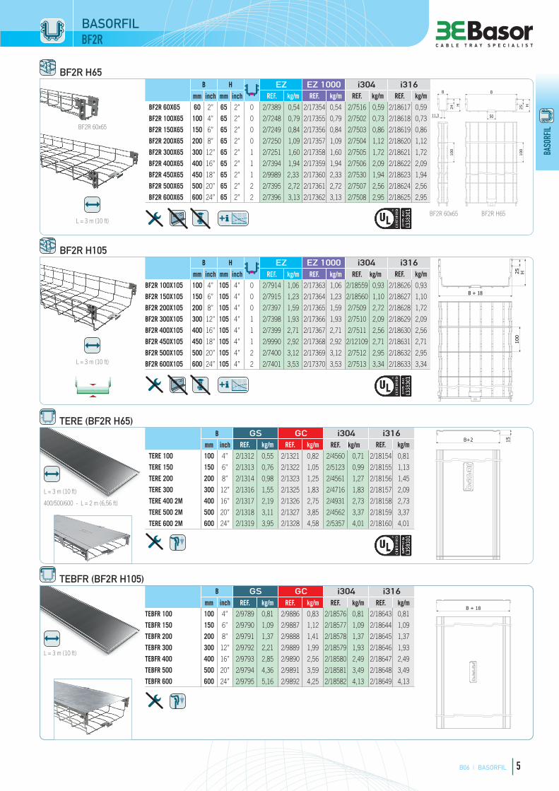
B06 I BASORFIL 5
BASO
RFIL
TERE (BF2R H65)B GS GC i304 i316
mm inch REF. kg/m REF. kg/m REF. kg/m REF. kg/mTERE 100 100 4” 2/1312 0,55 2/1321 0,82 2/4560 0,71 2/18154 0,81
TERE 150 150 6” 2/1313 0,76 2/1322 1,05 2/5123 0,99 2/18155 1,13
TERE 200 200 8” 2/1314 0,98 2/1323 1,25 2/4561 1,27 2/18156 1,45
TERE 300 300 12” 2/1316 1,55 2/1325 1,83 2/4716 1,83 2/18157 2,09
TERE 400 2M 400 16” 2/1317 2,19 2/1326 2,75 2/4931 2,73 2/18158 2,73
TERE 500 2M 500 20” 2/1318 3,11 2/1327 3,85 2/4562 3,37 2/18159 3,37
TERE 600 2M 600 24” 2/1319 3,95 2/1328 4,58 2/5357 4,01 2/18160 4,01
TEBFR (BF2R H105)B GS GC i304 i316
mm inch REF. kg/m REF. kg/m REF. kg/m REF. kg/mTEBFR 100 100 4” 2/9789 0,81 2/9886 0,83 2/18576 0,81 2/18643 0,81
TEBFR 150 150 6” 2/9790 1,09 2/9887 1,12 2/18577 1,09 2/18644 1,09
TEBFR 200 200 8” 2/9791 1,37 2/9888 1,41 2/18578 1,37 2/18645 1,37
TEBFR 300 300 12” 2/9792 2,21 2/9889 1,99 2/18579 1,93 2/18646 1,93
TEBFR 400 400 16” 2/9793 2,85 2/9890 2,56 2/18580 2,49 2/18647 2,49
TEBFR 500 500 20” 2/9794 4,36 2/9891 3,59 2/18581 3,49 2/18648 3,49
TEBFR 600 600 24” 2/9795 5,16 2/9892 4,25 2/18582 4,13 2/18649 4,13
BF2R H65B H EZ EZ 1000 i304 i316
mm inch mm inch REF. kg/m REF. kg/m REF. kg/m REF. kg/mBF2R 60X65 60 2” 65 2” 0 2/7389 0,54 2/17354 0,54 2/7516 0,59 2/18617 0,59
BF2R 100X65 100 4” 65 2” 0 2/7248 0,79 2/17355 0,79 2/7502 0,73 2/18618 0,73
BF2R 150X65 150 6” 65 2” 0 2/7249 0,84 2/17356 0,84 2/7503 0,86 2/18619 0,86
BF2R 200X65 200 8” 65 2” 0 2/7250 1,09 2/17357 1,09 2/7504 1,12 2/18620 1,12
BF2R 300X65 300 12” 65 2” 1 2/7251 1,60 2/17358 1,60 2/7505 1,72 2/18621 1,72
BF2R 400X65 400 16” 65 2” 1 2/7394 1,94 2/17359 1,94 2/7506 2,09 2/18622 2,09
BF2R 450X65 450 18” 65 2” 1 2/9989 2,33 2/17360 2,33 2/7530 1,94 2/18623 1,94
BF2R 500X65 500 20” 65 2” 2 2/7395 2,72 2/17361 2,72 2/7507 2,56 2/18624 2,56
BF2R 600X65 600 24” 65 2” 2 2/7396 3,13 2/17362 3,13 2/7508 2,95 2/18625 2,95
BF2R H105B H EZ EZ 1000 i304 i316
mm inch mm inch REF. kg/m REF. kg/m REF. kg/m REF. kg/mBF2R 100X105 100 4” 105 4” 0 2/7914 1,06 2/17363 1,06 2/18559 0,93 2/18626 0,93
BF2R 150X105 150 6” 105 4” 0 2/7915 1,23 2/17364 1,23 2/18560 1,10 2/18627 1,10
BF2R 200X105 200 8” 105 4” 0 2/7397 1,59 2/17365 1,59 2/7509 2,72 2/18628 1,72
BF2R 300X105 300 12” 105 4” 1 2/7398 1,93 2/17366 1,93 2/7510 2,09 2/18629 2,09
BF2R 400X105 400 16” 105 4” 1 2/7399 2,71 2/17367 2,71 2/7511 2,56 2/18630 2,56
BF2R 450X105 450 18” 105 4” 1 2/9990 2,92 2/17368 2,92 2/12109 2,71 2/18631 2,71
BF2R 500X105 500 20” 105 4” 2 2/7400 3,12 2/17369 3,12 2/7512 2,95 2/18632 2,95
BF2R 600X105 600 24” 105 4” 2 2/7401 3,53 2/17370 3,53 2/7513 3,34 2/18633 3,34
L = 3 m (10 ft)
BF2R 60x65
BF2R 60x65 BF2R H65
L = 3 m (10 ft)
B + 18
25 H10
0
BASORFILBF2R
B+2 15
L = 3 m (10 ft)
400/500/600 - L = 2 m (6,56 ft)
B + 18
L = 3 m (10 ft)
B
25 H
50
100
B
H
24
11,3
100

B06 I BASORFIL 11
BASO
RFIL
BASO
RFIL
B + 18
EBFR H65B H EZ GC
i304
i316
mm inch mm inch REF. kg/m REF. kg/mEBFR 100x65 100 4” 65 2” 2/7305 0,77 2/7326 0,83
EBFR 150x65 150 6” 65 2” 2/7306 0,82 2/7327 0,89
EBFR 200x65 200 8” 65 2” 2/7307 1,06 2/7328 1,15
EBFR 300x65 300 12” 65 2” 2/7308 1,57 2/7329 1,69
EBFR 400x65 400 16” 65 2” 2/7309 1,90 2/7330 2,05
EBFR 500x65 500 20” 65 2” 2/7310 2,46 2/7331 2,65
EBFR 600x65 600 24” 65 2” 2/7311 2,83 2/7332 3,05
B ≤ 200 2x CGBF (2/4364-EZ / 2/4360-GC)
B ≥300 3x CGBF (2/4364-EZ / 2/4360-GC)
L = 3 m (10 ft)
H-3
,5
50
B+18
100
TEBFRB GS GC
i304
i316
mm inch REF. kg/m REF. kg/mTEBFR 100 100 4” 2/9789 0,81 2/9886 1,05
TEBFR 150 150 6” 2/9790 1,09 2/9887 1,28
TEBFR 200 200 8” 2/9791 1,37 2/9888 1,61
TEBFR 300 300 12” 2/9792 2,21 2/9889 2,57
TEBFR 400 400 16” 2/9793 2,85 2/9890 3,31
TEBFR 500 500 20” 2/9794 4,36 2/9891 4,98
TEBFR 600 600 24” 2/9795 5,16 2/9892 5,89L = 3 m (10 ft)
BASORFILEBFR
EBFR H105B H EZ GC
i304
i316
mm inch mm inch REF. kg/m REF. kg/mEBFR 200x105 200 8” 105 4” 2/7312 1,57 2/7333 1,69
EBFR 300x105 300 12” 105 4” 2/7313 1,90 2/7334 2,05
EBFR 400x105 400 16” 105 4” 2/7314 2,46 2/7335 2,65
EBFR 500x105 500 20” 105 4” 2/7315 2,83 2/7336 3,05
EBFR 600x105 600 24” 105 4” 2/7316 3,20 2/7337 3,45
B ≤ 200 2x URBF (2/6217-EZ / 2/6219-GC)
B ≥300 2x URBF (2/6217-EZ / 2/6219-GC) + 1x CGBF (2/4364-EZ - 2/4360-GC)
L = 3 m (10 ft)
50
H+
4,5 24
B+18
100

B06 I BASORFIL 14
BASO
RFIL
BASO
RFIL
SSCEZ GC i304
REF. kg/ud REF. kg/ud REF. kg/udSSC 2/2064 0,03 2/0363 0,03 2/0340 0,03
M8
SSCEZ GC i304 i316
REF. kg/ud REF. kg/ud REF. kg/ud REF. kg/udSSC 2/2064 0,03 2/0363 0,03 2/0373 0,03 2/18553 0,03
M8
50
40
60
10
JUER-BFRi304 i316
REF. kg/ud REF. kg/udJUER-BFR 60/65 2/7018 0,18 2/18387 0,18
2 x CTBF + 2/100 x B1
35 55
30,5
10
3363
MUL GS i304 i316
mm REF. kg/ud REF. kg/ud REF. kg/udMU 500 500 2/0357 0,05 2/9872 0,06 2/14244 0,06
MU 275 275 2/10007 0,05
2 x CTBF
16
L25
18x7.5
GBFEZ GC i304 i316
REF. kg/ud REF. kg/ud REF. kg/ud REF. kg/udGBF 2/0337 0,01 2/0339 0,01 2/0340 0,01 2/1104 0,01
28
18
8x8
6
UCBFPap EZ GC i304Nm REF. kg/ud REF. kg/ud REF. kg/ud
UCBF 6 2/5059 0,025 2/5060 0,03 2/5093 0,03
Permite regulación
Conj. Torn. B1
BASORFIL
10
10

B06 I BASORFIL 15
BASO
RFIL
BASO
RFIL
SLGS GC i304
REF. kg/ud REF. kg/ud REF. kg/udSL 2/0355 0,08 2/0365 0,13 2/0375 0,08
Mod. 60x65 - 100x65.
6,50
10187
60 8025
1,50
13
SLSGS GC i304 i316
REF. kg/ud REF. kg/ud REF. kg/ud REF. kg/udSLS 2/0360 0,05 2/0370 0,05 2/0380 0,05 2/18561 0,05
BFR/BF2R 60x65 - 100x65 BFR/BF2R 60x65..200x65
30
12x8
18x7.5
2567 103
19
9
SSTGS
REF. kg/udSST 2/5724 0,03
H35 + VR8/VR10
STBFGS GC
REF. kg/ud REF. kg/udSTBF 100X35 2/9675 0,05 2/9857 0,07
STBF 60X65 2/17314 0,10
STBF 100X65 2/0886 0,13
1,5 25
31
10
11
25
5,5
120
70
7x7
9
30
BASORFIL

71
DATA SHEET SIMPLE LATERAL SUSPENSION (SLS)
UNE-EN 61537 REV.20/04/2016
www.basor.com
ER 50x50+TAPASIMPLE LATERAL SUSPENSION (SLS)
MOUNTING INSTRUCTIONS
Finishes: PG, HDG, SS304.
Characteristics:
- Metallic
- Non-! ame propagatinc component
- System with electrical continuity
- Electrically conductive component
- Minimum temperature of -50 ˚C
- Maximum temperature of 150 ˚C
- With metallic coating, resistance to corrosion:
PG coating: class 3
HDG coating: class 6
SS304 coating: class 9A
- The simple lateral suspension SLS is perfect for setting wall or ceiling installations trays BASORFIL 60x65 and 100x65 (width up to 200 for mounting to ceiling with threaded rod).
- For " xing to wall, the SLS has 8 mm holes for anchors or M6 hardware.
- To mount the trays to the ceiling, two SLS are required (one per wing). The SLS is mounted by passing the threaded rod (VR M8) and using two nuts M8 DIN 6923, one above and the other below.
- Maximum recommended distance between " xing points 1,5 m.
SAFE WORKING LOAD
Distance between
supports (m)
SWL*
(kg/m)
1 10
1,5 8
*NOTE: Loads for maximum de! ection of the tray in the attachment point to the support.
This technical data sheet issued accordingly to the ful" llment of the product Standard, is itself a necessary analyses of the electric risks according to the low tension Directive 2014/35/UE of February 26th 2014, in e# ect from April 20th 2016

B06 I BASORFIL 9
BASO
RFIL
BASO
RFIL
BASORFILBFR
TEREB GS GC i304 i316
mm inch REF. kg/m REF. kg/m REF. kg/m REF. kg/mTERE 100 100 4” 2/1312 0,55 2/1321 0,82 2/4560 0,71 2/18154 0,81
TERE 150 150 6” 2/1313 0,76 2/1322 1,14 2/5123 0,99 2/18155 1,13
TERE 200 200 8” 2/1314 0,98 2/1323 1,46 2/4561 1,27 2/18156 1,45
TERE 300 300 12” 2/1316 1,55 2/1325 2,11 2/4716 1,83 2/18157 2,09
TERE 400 2M 400 16” 2/1317 2,19 2/1326 2,75 - - - -
TERE 500 2M 500 20” 2/1318 3,11 2/1327 3,85 - - - -
TERE 600 2M 600 24” 2/1319 3,95 2/1328 4,58 - - - -
TERE 400 3M 400 16” - - - - 2/4931 2,73 2/18158 2,73
TERE 500 3M 500 20” - - - - 2/4562 3,37 2/18159 3,37
TERE 600 3M 600 24” - - - - 2/5357 4,01 2/18160 4,01
100/150/200/300
L = 3 m (10 ft)
TBF 60B GS GC i304
mm inch REF. kg/m REF. kg/m REF. kg/mTBF 60 1,5M 60 2” 2/6044 0,55 2/3614 0,63 2/5594 0,55
B+2
1500
L = 1,5 m (5 ft)

B06 I BASORFIL 13
BASO
RFIL
BASO
RFIL
ULAPap EZ GC i304Nm REF. kg/ud REF. kg/ud REF. kg/ud
ULA 65/105 6 2/4919 0,06 2/4363 0 ,08 2/4921 0,06
76
346
BASORFIL
JUBFR-AGS i304
REF. kg/ud Ref. kg/udJUBFR-A 65/105 2/9868 0,12 2/9869 0,12
2 x GBF (2/0337-EZ / 2/0340-i304) + 2 x B1 (2/4356-EZ / 2/4925-i304)
31 19
18x7,5
7
130
B1
CTBFPap EZ GC i304 i316Nm REF. kg/ud REF. kg/ud REF. kg/ud Ref. kg/ud
CTBF 6 2/4362 0,02 2/7132 0,02 2/4923 0,02 2/8229 0,02
20
M6
23
21
10
10
10

B06 I BASORFIL 12
BASO
RFIL
BASO
RFIL
URBFEZ GC
REF. kg/ud REF. kg/udURBF 65/105 2/6217 0,03 2/6219 0,03
URBF 35 2/7271 0,04 2/7272 0,04
65 / 105
105
65
52
52
25
12
34
46
4412
BASORFIL
UR BFR 65/105 EBFR 105
UR BFR 35
UREBFGS GC
REF. kg/ud REF. kg/udUREBF 65 2/9870 0,10 2/9871 0,11
65
24,5
8
9911
0
255
CGBFPap EZ GC i304 i316Nm REF. kg/ud REF. kg/ud REF. kg/ud REF. kg/ud
CGBF 6 2/4364 0,03 2/4360 0,03 2/4915 0,03 2/5358 0,03
CTBF + GBF
20
M6
28
18
10
URBF 65/105URBF 35
URBF 65/105
URBF 35
B<600
Recommended