Estimating Correspondences of Deformable Objects “In-the-wild”
Yuxiang Zhou⋆ Epameinondas Antonakos⋆ Joan Alabort-i-Medina⋆ Anastasios Roussos⋆
Stefanos Zafeiriou⋆,†
⋆Department of Computing, Imperial College London, U.K.†Center for Machine Vision and Signal Analysis, University of Oulu, Finland
yuxiang.zhou10, e.antonakos, ja310, troussos, [email protected]
Abstract
During the past few years we have witnessed the devel-
opment of many methodologies for building and fitting Sta-
tistical Deformable Models (SDMs). The construction of
accurate SDMs requires careful annotation of images with
regards to a consistent set of landmarks. However, the man-
ual annotation of a large amount of images is a tedious,
laborious and expensive procedure. Furthermore, for sev-
eral deformable objects, e.g. human body, it is difficult to
define a consistent set of landmarks, and, thus, it becomes
impossible to train humans in order to accurately annotate
a collection of images. Nevertheless, for the majority of
objects, it is possible to extract the shape by object segmen-
tation or even by shape drawing. In this paper, we show for
the first time, to the best of our knowledge, that it is pos-
sible to construct SDMs by putting object shapes in dense
correspondence. Such SDMs can be built with much less
effort for a large battery of objects. Additionally, we show
that, by sampling the dense model, a part-based SDM can
be learned with its parts being in correspondence. We em-
ploy our framework to develop SDMs of human arms and
legs, which can be used for the segmentation of the outline
of the human body, as well as to provide better and more
consistent annotations for body joints.
1. Introduction
Statistical Deformable Models (SDMs) of various ob-
jects is a well-studied and popular area in the intersection
of computer vision and machine learning [26, 24, 43, 54,
14, 64, 60]. Recently, we have witnessed tremendous de-
velopments on SDMs of human faces and bodies trained
with images that are captured under unconstrained condi-
tions, usually referred to as “in-the-wild” [14, 21, 64, 60,
11, 59, 12, 35, 2, 63, 8, 9, 3, 57]. This is attributed to:
• The abundance of complex visual data, spread through
web services (e.g. Youtube, Flickr, Google Images),
(a) MPII (b) Fashion (c) FLIC
Figure 1: Examples of inconsistent annotations of human
pose among different datasets. Blue markers denote the
original annotations. The arrows and green markers show
the correct location at which the points should be annotated.
Figure 2: Comparison of the standard landmark annotation
(red dots) with the curve annotation (blue lines) on arms,
ears and faces. It is evident that the curve annotations sur-
pass the inevitable inconsistency of sparse annotations.
which has led to the development of “in-the-wild”
databases of human faces and bodies [14, 37, 64, 20].
5791
• The manual annotation of such databases that has been
undertaken by several research teams [51, 22, 29, 7].
• The development of powerful visual features that are
able to describe objects and their parts in a robust man-
ner (e.g., SIFT [41], HoGs [27] ), as well as generative
and discriminative methodologies for learning SDMs.
However, there are two main drawbacks when building
SDMs directly on manually annotated landmarks:
• Annotating with regards to consistent landmarks is an
extremely time-consuming, tedious and labour inten-
sive work [52], which is usually performed by a trained
person. Furthermore, for various object classes, it re-
quires a highly skilled person in order to identify and
annotate landmarks in a consistent manner. For exam-
ple, the human ear has very complicated inner struc-
tures (helix, crus antihelicis, scapha, tragus, lobe etc.)
which remarkably differ between different ears. More-
over, certain ear parts, such as fossa triangularies and
crus helicis, do not appear in all ears and their visibil-
ity is highly sensitive to the head pose and illumination
variation. Another such example is the human body,
which is generally annotated with regards to a num-
ber of landmarks that intuitively correspond to a set of
body joints. For most body pose databases, the anno-
tation task was undertaken by a crowd-sourcing Inter-
net marketplace, so-called Amazon Mechanical Turk
(AMT). Unfortunately, this resulted in acquiring in-
consistent and inaccurate annotations, in many cases1
(please see Figure 1). As it was also recently pointed
out [56], the inconsistencies in body joint annotations
may also render the comparison between different hu-
man pose estimation methodologies irrelevant.
• The nature of many deformable objects does not allow
them to be annotated with regards to a consistent set
of landmarks (e.g., bottles, fruits etc.). Additionally,
it is very difficult to consistently annotate the outline
of certain objects such as faces, ears, body, since these
landmarks do not have any semantic meaning. That
is why many state-of-the-art methods opt to leave the
boundary out when reporting results [59, 12]. The ma-
jority of the state-of-the-art methods for model-based
landmark localisation [21, 64, 60, 59, 12] are not ap-
plicable to objects with inconsistent sets of landmarks.
To illustrate how time-consuming careful annotation of a
complex deformable object is, we lay down our own experi-
ence based on the human ear. A trained annotator needs an
average of 4 minutes per image for the manual annotation
1In the case of faces, the quality of annotations produced from AMT
are extremely inaccurate and cannot, by any means, be compared with the
ones provided by the recent 300W competition [52, 51].
of 55 landmarks. This means that the annotation of 1000
images requires a total of about 67 hours. Furthermore, the
quality of training as well as fatigue greatly influence the
annotation accuracy. Hence, a second pass on the anno-
tated data is, in many cases, necessary. Due to the fact that
manual annotation is a costly and labour-intensive proce-
dure, unsupervised learning of deformable models for the
task of object alignment has recently attracted some atten-
tion [30, 13, 25, 34, 32, 36, 33, 40, 62]. However, because
the problem of fully unsupervised discovery of the deforma-
tions of arbitrary objects is difficult and ill-posed, the lim-
ited number of methods that have been proposed for the task
cannot be directly applied to arbitrary collections of “in-the-
wild” images. On the other hand, the method of [10], which
can deal with “in-the-wild” images, requires a set of consis-
tently annotated sparse shapes to perform deformable face
congealing.
2. Contributions
In this paper, we propose a solution for annotating an
object with regards to its deformations that requires consid-
erably less effort compared to manual annotation and, at the
same time, can be used to define statistical deformations for
objects without a consistent set of landmarks. We employ
the proposed method in order to construct SDMs based on
the outline of human body parts (i.e., arms and legs). The
proposed SDM can also be used to provide accurate and
consistent annotations for several of the body joints (such
as wrist, elbow etc.). To this end, we argue and empirically
demonstrate that it is better to annotate an object with re-
gards to a set of continuous lines that describe its shape. An
example is provided in Figure 2, which compares the stan-
dard landmark annotations that are employed in the current
literature with the proposed curve annotations for arms, ears
and faces. It becomes evident that the curve annotations
avoid the inherent ambiguity of placing sparse landmarks
and offer a richer description of the object’s shape. Fur-
thermore, these curves can be automatically generated by
recently proposed methods that perform discriminative seg-
mentation of objects [42, 39]. Note that the work in [65]
is the only one that shows that training SDMs based on the
outline contours of the human body parts has considerable
advantages compared to using the sparse skeleton joints, as
done by the majority of existing SDMs for human pose.
Furthermore, we capitalise on recent advances on mul-
tiframe optical flow estimation [31, 49, 55] and show that
the relevant methodologies have matured enough to densely
annotate the proposed shapes using either simplistic or even
more sophisticated and robust shape representation methods
[44]. In particular, in order to build dense correspondences
between different shape instances of the same object class,
we jointly estimate the optical flow among all the instances
by imposing low-rank constrains, an approach that we call
5792

Shape Flow. Multiframe optical flow has originally been
applied on video sequences, relying on the assumptions of
colour consistency and motion smoothness [31]. However,
these assumptions do not hold in our case, where we have
a collection of shapes. Therefore, we introduce appropri-
ate modifications based on the consistency of image-based
shape representation, as well as low-rank priors.
Additionally, we show that the proposed methodology
can be applied on landmark localisation, even though it is
not tailored for that task, achieving particularly good per-
formance. Specifically, we explain how to build powerful
dense SDMs that are suitable for objects that have rich in-
terior texture but lack landmarks consistency. Furthermore,
we show how to build a powerful patch-based SDM on the
sparse outline landmarks of objects that do not have se-
mantically meaningful interior textures. Using the result-
ing outline patch-based SDM, we report state-of-the-art per-
formance on the task of human body parts localisation on
challenging databases. Finally, we show that the proposed
patch-based SDM can be used to provide consistent annota-
tions for different body parts.
In summary, the contributions of this paper are:
• We propose one of the first, to the best of our knowl-
edge, methodologies that constructs accurate SDMs
from a set of training data with inconsistent anno-
tations. We show that the proposed methodology
tremendously reduces the manual workload thanks to
the highly effective curve annotations.
• We illustrate the ability of the proposed method to gen-
erate consistent sparse landmark annotations for ob-
ject classes which, by nature, make it impossible to be
manually annotated in a consistent way.
• We show that it is more advantageous to model the hu-
man body parts (e.g. arms) with a set of sparse land-
marks on their outline, rather than on their skeleton
joints. This is because the outline landmarks, which
can be acquired by our method in a straightforward
way, exhibit better consistency compared to the in-
evitable inconsistency of the joint landmarks.
• We report state-of-the-art quantitative and qualitative
results on human body parts localisation by employing
a patch-based SDM trained on the outline landmarks
that are sampled by the dense correspondences. Our
proposed model outperforms all current state-of-the-
art techniques that are trained on skeleton joints.
• We show that the employed patch-based SDM corrects
the annotations that are currently provided for most
major human body pose databases 2.
2The corrected annotations are publicly available in
http://www.ibug.doc.ic.ac.uk/resources/
bodypose-anno-correction.
3. Constructing Deformable Models with
Shape Flow
This section presents the proposed method for establish-
ing dense correspondences among training shapes by only
using curve annotations. It takes as input a set of train-
ing images of a particular object class, along with the cor-
responding curve annotations. The steps of our pipeline,
which are also depicted in Figure 3, are the following:
Step 1: Represent the curve annotations in a consistent way
using a multichannel extension of the Support Vector Shape
(SVS) representation [44]. Apply the Iterative Closest Point
(ICP) algorithm [16] to achieve an initial alignment of the
SVS images.
Step 2: Construct a correspondence basis for the training
SVS images. This is acquired by applying the Non-rigid
ICP (NICP) algorithm of [5] on the densely sampled an-
notated curves, followed by Principal Component Analysis
(PCA).
Step 3: Establish dense correspondences between all the
shapes in the training set by feeding the multichannel
similarity-aligned SVS images into a multi-image subspace
flow estimation.
Step 4: Utilise the dense correspondences acquired by the
optical flow in order to automatically generate either dense
or sparse (on the outline) landmark annotations, depending
on the object class type. Then, build either a dense [48, 4, 6]
or a patch-based [59] AAM, respectively.
The upcoming sections discuss each of the aforemen-
tioned steps in further detail.
Step 1: Shape Representation Based on SupportVector Shapes
In order to fully capture the variability among most de-
formable objects’ shapes annotations, we use a represen-
tation based on SVS [44]. An SVS is a decision function
trained on shapes using Support Vector Machines (SVMs)
with Radial Basis Function (RBF) kernels. In this way,
a shape is represented as a classifier function, which has
several advantages: (a) the representation is completely
generic, e.g. it can be applied to sparse landmark points,
curves lines or a combination of the two, and (b) it fuses
inconsistent landmarks into consistent and directly compa-
rable decision functions. Furthermore, this representation is
also robust against noise, missing data and outliers [44].
The curve annotations for all training images are densely
sampled to yield a set of landmarks per image, with this set
being different for every training image. To train the SVM,
these landmarks are assigned as belonging to the ‘positive’
class, whereas randomly sampled points around them are
assigned as belonging to the ‘negative’ class. Since the
positive class has far less points than the negative class,
landmarks are assigned considerably larger weights so that
5793
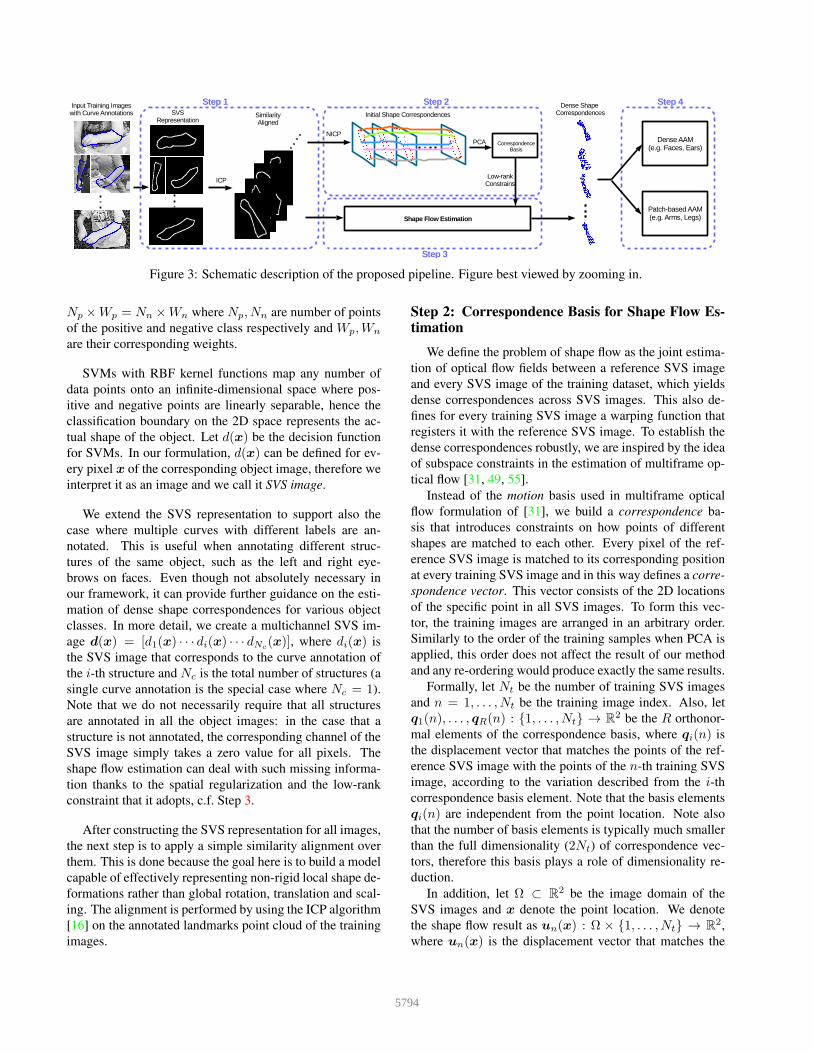
Figure 3: Schematic description of the proposed pipeline. Figure best viewed by zooming in.
Np ×Wp = Nn ×Wn where Np, Nn are number of points
of the positive and negative class respectively and Wp,Wn
are their corresponding weights.
SVMs with RBF kernel functions map any number of
data points onto an infinite-dimensional space where pos-
itive and negative points are linearly separable, hence the
classification boundary on the 2D space represents the ac-
tual shape of the object. Let d(x) be the decision function
for SVMs. In our formulation, d(x) can be defined for ev-
ery pixel x of the corresponding object image, therefore we
interpret it as an image and we call it SVS image.
We extend the SVS representation to support also the
case where multiple curves with different labels are an-
notated. This is useful when annotating different struc-
tures of the same object, such as the left and right eye-
brows on faces. Even though not absolutely necessary in
our framework, it can provide further guidance on the esti-
mation of dense shape correspondences for various object
classes. In more detail, we create a multichannel SVS im-
age d(x) = [d1(x) · · · di(x) · · · dNc(x)], where di(x) is
the SVS image that corresponds to the curve annotation of
the i-th structure and Nc is the total number of structures (a
single curve annotation is the special case where Nc = 1).
Note that we do not necessarily require that all structures
are annotated in all the object images: in the case that a
structure is not annotated, the corresponding channel of the
SVS image simply takes a zero value for all pixels. The
shape flow estimation can deal with such missing informa-
tion thanks to the spatial regularization and the low-rank
constraint that it adopts, c.f. Step 3.
After constructing the SVS representation for all images,
the next step is to apply a simple similarity alignment over
them. This is done because the goal here is to build a model
capable of effectively representing non-rigid local shape de-
formations rather than global rotation, translation and scal-
ing. The alignment is performed by using the ICP algorithm
[16] on the annotated landmarks point cloud of the training
images.
Step 2: Correspondence Basis for Shape Flow Estimation
We define the problem of shape flow as the joint estima-
tion of optical flow fields between a reference SVS image
and every SVS image of the training dataset, which yields
dense correspondences across SVS images. This also de-
fines for every training SVS image a warping function that
registers it with the reference SVS image. To establish the
dense correspondences robustly, we are inspired by the idea
of subspace constraints in the estimation of multiframe op-
tical flow [31, 49, 55].
Instead of the motion basis used in multiframe optical
flow formulation of [31], we build a correspondence ba-
sis that introduces constraints on how points of different
shapes are matched to each other. Every pixel of the ref-
erence SVS image is matched to its corresponding position
at every training SVS image and in this way defines a corre-
spondence vector. This vector consists of the 2D locations
of the specific point in all SVS images. To form this vec-
tor, the training images are arranged in an arbitrary order.
Similarly to the order of the training samples when PCA is
applied, this order does not affect the result of our method
and any re-ordering would produce exactly the same results.
Formally, let Nt be the number of training SVS images
and n = 1, . . . , Nt be the training image index. Also, let
q1(n), . . . , qR(n) : 1, . . . , Nt → R2 be the R orthonor-
mal elements of the correspondence basis, where qi(n) is
the displacement vector that matches the points of the ref-
erence SVS image with the points of the n-th training SVS
image, according to the variation described from the i-th
correspondence basis element. Note that the basis elements
qi(n) are independent from the point location. Note also
that the number of basis elements is typically much smaller
than the full dimensionality (2Nt) of correspondence vec-
tors, therefore this basis plays a role of dimensionality re-
duction.
In addition, let Ω ⊂ R2 be the image domain of the
SVS images and x denote the point location. We denote
the shape flow result as un(x) : Ω × 1, . . . , Nt → R2,
where un(x) is the displacement vector that matches the
5794

Figure 4: Exemplar deformation fields for the left arm, ob-
tained using the proposed pipeline. Figure best viewed by
zooming in.
point x of the reference SVS image with its corresponding
location at the n-th training SVS image.
Using the constructed correspondence basis, the shape
flow can be approximated as:
un(x) ≈∑R
i=1qi(n)vi(x) , (1)
where vi(x) is the weight that needs to be applied on the
i-th correspondence basis element, in order to get the corre-
spondence vector for the point location x. In other words,
the shape flow for every point x is described as a linear
combination of basis elements that is controlled by the co-
efficients vi(x). The values of the i-th coefficient for all
the points vi(x) can be interpreted as an image defined on
Ω. Using the correspondence basis, the determination of
the shape flow boils down to the determination of the set
of coefficients vi(x). The above representation of shape
flow, constrains the correspondence vectors to lie on a sub-
space and, therefore, acts as a low-rank prior that enforces
coherency of the shape registration result over the whole
training dataset of shapes.
To effectively build the correspondence basis, we first
transform the original annotations to sparse point clouds.
Then, we apply the NICP algorithm of [5] between the point
cloud of annotations in the reference shape and the one of
every shape of the training set. NICP iteratively deforms
the cloud of points of every shape to match the points of
the reference shape. This yields an initial estimation of the
correspondence vectors on the sparse locations of annotated
landmarks on the reference shape. Finally, the correspon-
dence basis is found by applying PCA on these correspon-
dence vectors and keeping only the first R principal compo-
nents.
Step 3: Shape Flow Estimation
As already mentioned, our shape flow estimation builds
upon robust methods for multiframe optical flow estima-
tion [31]. However, optical flow estimation typically works
based on the assumptions of brightness or colour constancy
and motion smoothness, whereas in our setting the input
training data correspond to shapes. For this reason, we pro-
pose to modify the formulation of [31] by using the corre-
spondence basis that we introduced in conjunction with the
SVS representation of shapes.
Let d(x;n), d(x; 0) : Ω → RNc be the n-th training
SVS image and the reference SVS image respectively. Fol-
lowing [31], we propose to estimate the shape flow over all
training images by minimizing the following energy:
Esf = α
∫Ω
Nt∑n=1
‖d(x+ un(x);n)− d(x; 0)‖dx (2)
+ β
∫Ω
Nt∑n=1
‖un(x)−R∑i=1
qi(n)vi(x)‖2dx (3)
+
∫Ω
R∑i=1
‖∇vi(x)‖ dx (4)
This energy consists of two sets of unknown shape flows
that are relatively close to each other: (i) un(x) which tries
to explain the data from the input SVS images, and (ii) the
shape flow determined by the correspondence basis coef-
ficients vi(x) that are spatially regularised and enforce a
low-rank prior.
The first term of the above energy (2) is a data attach-
ment term that uses the robust L1-norm. It is based on
the assumption that the values of the reference SVS image
d0(x) at every pixel x are preserved at its corresponding
locations on all training SVS images dn(x). The use of an
L1-norm improves the robustness of the method since it al-
lows deviations from this assumption, which might occur in
practice. The second term of the energy (3) penalizes the
difference between the two sets of shape flows and acts as a
coupling term between them. The third term of the energy
(4) corresponds to the spatial Total Variation regularization
[50] of the correspondence basis coefficients vi(x). This
term penalizes spatial oscillations of each coefficient caused
by distortions of the SVS images but not strong disconti-
nuities that are desirable in the borders of different object
regions. In addition, this term allows to fill in information
into regions where the shape information in the SVS images
is missing, due to e.g. regions with no annotations.
We implement the minimization of the energy Esf by us-
ing the optimization algorithm described in [31]. For more
details, please refer to the Supplementary Material. Fig-
ure 4 shows some examples of deformation fields derived
from the estimated shape flow computed by the aforemen-
Figure 5: Dense shape models build for faces and ears.
Dense shapes are presented as grid for better visualization.
5795

tioned method. These results correspond to exemplar train-
ing shapes in the case of an arm dataset. We observe that the
shape flow estimation captures the shape and deformations
of the human arm in a plausible way.
Step 4: Dense and PatchBased Deformable Models
The deformation fields obtained from Step 3 can be used
to naturally build two different kinds of effective Active Ap-
pearance Models (AAMs) [24, 43]: dense [48, 4, 6] and
patch-based [59]. The only difference between these two
AAM formulations is on the way that the shape is repre-
sented and, thus, the manner in which the texture is sam-
pled. Each one of them is suitable for object classes with
specific properties. The dense AAM provides an excep-
tionally effective modeling and fitting for non-articulated
objects, such as ears and faces, whose appearance has char-
acteristic structures that spread all over their region (even if
these structures cannot be consistently annotated). On the
other hand, there exist other challenging object classes, such
as arms and legs, that not only cannot be consistently an-
notated with landmarks, but their appearance is distinctive
only on the object’s outline and not in its interior region.
Especially in the case of human body parts, they are almost
always covered by clothes, which makes it impossible to
construct robust texture models.
Dense Active Appearance Model Since all the deforma-
tion fields acquired by Step 3 are defined for the pixels of
the reference SVS image, the spatial positions xi = (xi, yi)of these pixels can be treated as point landmarks and the de-
formation fields as dense annotations of the object’s shape.
Consequently, building a dense shape model reduces to nor-
malising these dense annotations with respect to a global
similarity transform (typically using Procrustes Analysis)
and applying PCA. A shape instance can be generated by
the resulting shape model as:
s(p) = s+ Sp (5)
where s is mean shape, and S and p are the shape bases and
shape parameters, respectively.
By making explicit use of the one-to-one correspon-
dence between pixels on the reference frame and on the
deformation fields, the motion model of sparse holistic
AAMs [24, 43] (piece-wise affine, thin-plates splines [17])
is replaced by sampling all pixel values onto the reference
frame. Let us define this sampling function, given a shape
instance s(p), as W(s(p)). Once the images have been
warped, the texture model is obtained by applying PCA on
them. A texture instance can be generated as:
t(c) = t+ Tc (6)
where t is the mean texture, and T and c are the texture
bases and texture parameters, respectively.
Given a test image I, the fitting process involves the min-
imization of the following cost function:
argminp,c
‖I(W(s(p)))− t(c)‖22 (7)
This optimization problem is typically solved using the
inverse-compositional Gauss-Newton algorithm, for which
different variations have been proposed [43, 45, 4, 58, 2].
Note that the existence of the sampling function W() in-
stead of a non-linear warping function has the advantage
that all existing efficient gradient descent algorithms be-
come exact.
Outline Patch-Based Active Appearance Model (PAAM)
The object classes for which the interior appearance does
not have specific structure are modeled using patch-based
AAMs [59] trained on a set of sparse landmarks. Especially
for human body parts (arms, legs), we strongly believe that
the points located to the outline of the object are more suit-
able compared to the internal ones that correspond to the
skeleton joints, which are commonly used by current litera-
ture [19, 22, 46, 61].
The main differences between the patch-based and dense
AAMs are that (a) the densified shape instances are sub-
sampled to include only the outline points, and (b) the tex-
ture representation involves the sampling a neighbourhood
around each point instead of a single pixel. Specifically, in
order to build the outline sparse shape model, we simply se-
lect the outline points on the SVS reference frame. Then,
by taking advantage of the dense correspondences obtained
by Step 3, the shape model is trained in a similar way as in
the dense case. Moreover, similar to the dense case, the tex-
ture model is built by sampling the image values from the
sparse shape locations, i.e. W(s(p)). However, contrary
to dense AAMs, we sample a patch that is centred around
each landmark point. These patches are then vectorised and
concatenated in a single texture vector. Note that the opti-
mization process remains exactly the same.
4. Experimental Evaluation
We evaluate the performance of the proposed methodol-
ogy for the task of human body pose correspondence esti-
mation, as well as non-rigid alignment “in-the-wild”. For
further experimental results, please refer to the supplemen-
tary material. Note that all steps of the proposed pipeline
were implemented using the Menpo Project [1].
4.1. Nonrigid Object Alignment IntheWild
Herein, we compare the fitting accuracy of the dAAMs
that are trained with our proposed framework with holistic
sparse AAMs [24, 43, 8]. We consider two object classes
that demonstrate rich texture: face and ear.
5796
SHOULDER
ELBOW
WRIST
2.20
2.28
2.36
2.44
2.52
Norm
alized
Sta
ndard
Devia
tion (
%)
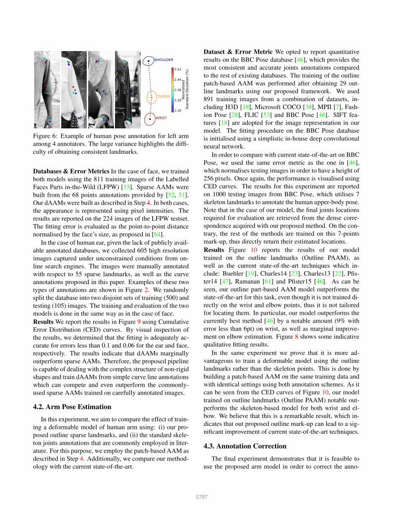
Figure 6: Example of human pose annotation for left arm
among 4 annotators. The large variance highlights the diffi-
culty of obtaining consistent landmarks.
Databases & Error Metrics In the case of face, we trained
both models using the 811 training images of the Labelled
Faces Parts in-the-Wild (LFPW) [15]. Sparse AAMs were
built from the 68 points annotations provided by [52, 51].
Our dAAMs were built as described in Step 4. In both cases,
the appearance is represented using pixel intensities. The
results are reported on the 224 images of the LFPW testset.
The fitting error is evaluated as the point-to-point distance
normalised by the face’s size, as proposed in [64].
In the case of human ear, given the lack of publicly avail-
able annotated databases, we collected 605 high resolution
images captured under unconstrained conditions from on-
line search engines. The images were manually annotated
with respect to 55 sparse landmarks, as well as the curve
annotations proposed in this paper. Examples of these two
types of annotations are shown in Figure 2. We randomly
split the database into two disjoint sets of training (500) and
testing (105) images. The training and evaluation of the two
models is done in the same way as in the case of face.
Results We report the results in Figure 9 using Cumulative
Error Distribution (CED) curves. By visual inspection of
the results, we determined that the fitting is adequately ac-
curate for errors less than 0.1 and 0.06 for the ear and face,
respectively. The results indicate that dAAMs marginally
outperform sparse AAMs. Therefore, the proposed pipeline
is capable of dealing with the complex structure of non-rigid
shapes and train dAAMs from simple curve line annotations
which can compete and even outperform the commonly-
used sparse AAMs trained on carefully annotated images.
4.2. Arm Pose Estimation
In this experiment, we aim to compare the effect of train-
ing a deformable model of human arm using: (i) our pro-
posed outline sparse landmarks, and (ii) the standard skele-
ton joints annotations that are commonly employed in liter-
ature. For this purpose, we employ the patch-based AAM as
described in Step 4. Additionally, we compare our method-
ology with the current state-of-the-art.
Dataset & Error Metric We opted to report quantitative
results on the BBC Pose database [46], which provides the
most consistent and accurate joints annotations compared
to the rest of existing databases. The training of the outline
patch-based AAM was performed after obtaining 29 out-
line landmarks using our proposed framework. We used
891 training images from a combination of datasets, in-
cluding H3D [18], Microsoft COCO [38], MPII [7], Fash-
ion Pose [28], FLIC [53] and BBC Pose [46]. SIFT fea-
tures [18] are adopted for the image representation in our
model. The fitting procedure on the BBC Pose database
is initialised using a simplistic in-house deep convolutional
neural network.
In order to compare with current state-of-the-art on BBC
Pose, we used the same error metric as the one in [46],
which normalises testing images in order to have a height of
256 pixels. Once again, the performance is visualised using
CED curves. The results for this experiment are reported
on 1000 testing images from BBC Pose, which utilises 7
skeleton landmarks to annotate the human upper-body pose.
Note that in the case of our model, the final joints locations
required for evaluation are retrieved from the dense corre-
spondence acquired with our proposed method. On the con-
trary, the rest of the methods are trained on this 7-points
mark-up, thus directly return their estimated locations.
Results Figure 10 reports the results of our model
trained on the outline landmarks (Outline PAAM), as
well as the current state-of-the-art techniques which in-
clude: Buehler [19], Charles14 [23], Charles13 [22], Pfis-
ter14 [47], Ramanan [61] and Pfister15 [46]. As can be
seen, our outline part-based AAM model outperforms the
state-of-the-art for this task, even though it is not trained di-
rectly on the wrist and elbow points, thus it is not tailored
for locating them. In particular, our model outperforms the
currently best method [46] by a notable amount (9% with
error less than 6pt) on wrist, as well as marginal improve-
ment on elbow estimation. Figure 8 shows some indicative
qualitative fitting results.
In the same experiment we prove that it is more ad-
vantageous to train a deformable model using the outline
landmarks rather than the skeleton points. This is done by
building a patch-based AAM on the same training data and
with identical settings using both annotation schemes. As it
can be seen from the CED curves of Figure 10, our model
trained on outline landmarks (Outline PAAM) notable out-
performs the skeleton-based model for both wrist and el-
bow. We believe that this is a remarkable result, which in-
dicates that out proposed outline mark-up can lead to a sig-
nificant improvement of current state-of-the-art techniques.
4.3. Annotation Correction
The final experiment demonstrates that it is feasible to
use the proposed arm model in order to correct the anno-
5797

Figure 7: Demonstration of annotation correction using our method for the experiment of Section 4.3. Red dots refer to
officially provided landmarks, and green dots are corrected position.
Figure 8: Demonstration of outline fitting of patch-based AAM on arms.
tations provided by current datasets. As mentioned above
there are inconsistencies in the annotations of MPII [7],
Fashion Pose [28] and FLIC [53]. Due to the large vari-
ance in arm pose, it is difficult even for trained annotators
to obtain consistent annotations between them. As proof of
concept, Figure 6 reports the standard deviation observed
between the annotations of 4 trained humans that were re-
quested to annotate 120 images of left arms from Fashion
Pose [28] with respect to the shoulder, elbow and wrist.
0.00 0.02 0.04 0.06 0.08 0.10Normalized Point-to-Point Error
0.0
0.2
0.4
0.6
0.8
1.0
Images Proportion
Face
0.00 0.02 0.04 0.06 0.08 0.10 0.12 0.14Normalized Point-to-Point Error
0.0
0.2
0.4
0.6
0.8
1.0
Images Proportion
Ears
Figure 9: CEDs of faces and ears fitting performance for the
experiment of Section 4.1.
0 5 10 15Normalized Point-to-Point Error
0.0
0.2
0.4
0.6
0.8
1.0
Images Proportion
Wrist
0 5 10 15Normalized Point-to-Point Error
0.0
0.2
0.4
0.6
0.8
1.0
Images Proportion
Elbow
Figure 10: CEDs over skeleton landmarks on BBC Pose
database for the experiment of Section 4.2.
By applying our outline patch-based AAM on the afore-
mentioned databases, we managed to greatly correct the
currently available annotations of the arm. Figure 7 shows
indicative examples of the corrected landmarks. There is no
doubt that points after correction demonstrate more consis-
tency among images. We make the corrected annotations
publicly available2.
5. Conclusion
Learning and fitting statistical deformable models
(SDMs) is one of the most important areas in computer vi-
sion. Generally, in order to train a SDM, a set of predefined
correspondences are required. In some objects, such as hu-
man face, semantically meaningful correspondences can be
found, but require laborious manual annotations; on other
objects it is very difficult, or even impossible. In this paper,
we propose one of the first comprehensive procedures for
establishing correspondences (that do not necessarily corre-
spond to semantically meaningful object landmarks) in ar-
bitrary objects with minimal amount of human annotation.
We apply the proposed approach for the construction of the
first, to the best of our knowledge, highly-descriptive SDM
for the human arm.
Acknowledgements The work of E. Antonakos was par-
tially funded by the EPSRC project EP/J017787/1 (4D-
FAB). The work of J. Alabort-i-Medina was partially
funded by an EPSRC DTA. The work of A. Roussos
was partially funded by the EPSRC project EP/N007743/1
(FACER2VM). The work of S. Zafeiriou was partially
funded by the FiDiPro program of Tekes (project num-
ber: 1849/31/2015), as well as by the European Community
Horizon 2020 [H2020/2014-2020] under grant agreement
no. 688520 (TeSLA).
5798

References
[1] J. Alabort-i-Medina, E. Antonakos, J. Booth, P. Snape, and
S. Zafeiriou. Menpo: A comprehensive platform for para-
metric image alignment and visual deformable models. In
Proceedings of the ACM International Conference on Multi-
media, MM ’14, pages 679–682, New York, NY, USA, 2014.
ACM. 6
[2] J. Alabort-i-Medina and S. Zafeiriou. Bayesian active ap-
pearance models. In Conference on Computer Vision and
Pattern Recognition (CVPR), 2014. 1, 6
[3] J. Alabort-i-Medina and S. Zafeiriou. Unifying holistic and
parts-based deformable model fitting. In Proceedings of
IEEE International Conference on Computer Vision and Pat-
tern Recognition (CVPR’15), Boston, MA, USA, June 2015.
1
[4] B. Amberg, A. Blake, and T. Vetter. On compositional image
alignment, with an application to active appearance models.
In Conference on Computer Vision and Pattern Recognition
(CVPR), 2009. 3, 6
[5] B. Amberg, S. Romdhani, and T. Vetter. Optimal step non-
rigid ICP algorithms for surface registration. In Conference
on Computer Vision and Pattern Recognition (CVPR), 2007.
3, 5
[6] R. Anderson, B. Stenger, and R. Cipolla. Using bounded
diameter minimum spanning trees to build dense active ap-
pearance models. International Journal of Computer Vision,
110(1):48–57, 2014. 3, 6
[7] M. Andriluka, L. Pishchulin, P. Gehler, and B. Schiele. 2d
human pose estimation: New benchmark and state of the art
analysis. In IEEE Conference on Computer Vision and Pat-
tern Recognition (CVPR), June 2014. 2, 7, 8
[8] E. Antonakos, J. Alabort-i-Medina, G. Tzimiropoulos, and
S. Zafeiriou. Feature-based lucas-kanade and active ap-
pearance models. IEEE Transactions on Image Processing,
24(9):2617–2632, September 2015. 1, 6
[9] E. Antonakos, J. Alabort-i-Medina, and S. Zafeiriou. Ac-
tive pictorial structures. In Proceedings of IEEE Interna-
tional Conference on Computer Vision and Pattern Recogni-
tion (CVPR’15), pages 5435–5444, Boston, MA, USA, June
2015. 1
[10] E. Antonakos and S. Zafeiriou. Automatic construction of
deformable models in-the-wild. In Proceedings of IEEE
International Conference on Computer Vision & Pattern
Recognition (CVPR’14), pages 1813–1820, Columbus, OH,
USA, June 2014. 2
[11] A. Asthana, S. Zafeiriou, S. Cheng, and M. Pantic. Ro-
bust discriminative response map fitting with constrained lo-
cal models. In Conference on Computer Vision and Pattern
Recognition (CVPR), 2013. 1
[12] A. Asthana, S. Zafeiriou, S. Cheng, and M. Pantic. Incre-
mental face alignment in the wild. In Conference on Com-
puter Vision and Pattern Recognition (CVPR), 2014. 1, 2
[13] S. Baker, I. Matthews, and J. Schneider. Automatic construc-
tion of active appearance models as an image coding prob-
lem. IEEE Transactions on Pattern Analysis and Machine
Intelligence, 26(10):1380, 2004. 2
[14] P. N. Belhumeur, D. W. Jacobs, D. J. Kriegman, and N. Ku-
mar. Localizing parts of faces using a consensus of exem-
plars. In Conference on Computer Vision and Pattern Recog-
nition (CVPR), 2011. 1
[15] P. N. Belhumeur, D. W. Jacobs, D. J. Kriegman, and N. Ku-
mar. Localizing parts of faces using a consensus of ex-
emplars. Pattern Analysis and Machine Intelligence, IEEE
Transactions on, 35(12):2930–2940, 2013. 7
[16] P. Besl and N. D. McKay. A method for registration of 3-d
shapes. Transactions on Pattern Analysis and Machine Intel-
ligence (TPAMI), 1992. 3, 4
[17] F. J. Bookstein. Principal warps: Thin-plate splines and
the decomposition of deformations. Transactions on Pattern
Analysis and Machine Intelligence (TPAMI), 11(6):567–585,
1989. 6
[18] L. Bourdev and J. Malik. Poselets: Body part detectors
trained using 3d human pose annotations. In International
Conference on Computer Vision, sep 2009. 7
[19] P. Buehler, M. Everingham, D. P. Huttenlocher, and A. Zis-
serman. Upper body detection and tracking in extended sign-
ing sequences. International journal of computer vision,
95(2):180–197, 2011. 6, 7
[20] X. P. Burgos-Artizzu, P. Perona, and P. Dollr. Robust face
landmark estimation under occlusion. In International Con-
ference on Computer Vision (ICCV), 2013. 1
[21] X. Cao, Y. Wei, F. Wen, and J. Sun. Face alignment by
explicit shape regression. In Computer Vision and Pattern
Recognition (CVPR), 2012. 1, 2
[22] J. Charles, T. Pfister, D. Magee, D. Hogg, and A. Zisserman.
Domain adaptation for upper body pose tracking in signed
tv broadcasts. In Proceedings of the British machine vision
conference, 2013. 2, 6, 7
[23] J. Charles, T. Pfister, D. Magee, D. Hogg, and A. Zisser-
man. Upper body pose estimation with temporal sequential
forests. In Proceedings of the British Machine Vision Con-
ference 2014, pages 1–12. BMVA Press, 2014. 7
[24] T. F. Cootes, G. J. Edwards, and C. J. Taylor. Active appear-
ance models. Transactions on Pattern Analysis and Machine
Intelligence (TPAMI), 2001. 1, 6
[25] T. F. Cootes, S. Marsland, C. J. Twining, K. Smith, and C. J.
Taylor. Groupwise diffeomorphic non-rigid registration for
automatic model building. In Computer Vision-ECCV 2004,
pages 316–327. Springer, 2004. 2
[26] T. F. Cootes, C. J. Taylor, D. H. Cooper, and J. Graham. Ac-
tive shape models: Their training and application. Computer
Vision and Image Understanding, 1995. 1
[27] N. Dalal and B. Triggs. Histograms of oriented gradients
for human detection. In Conference on Computer Vision and
Pattern Recognition (CVPR), pages 886–893, 2005. 2
[28] M. Dantone, J. Gall, C. Leistner, and L. Van Gool. Human
pose estimation using body parts dependent joint regressors.
In Computer Vision and Pattern Recognition (CVPR), 2013
IEEE Conference on, pages 3041–3048. IEEE, 2013. 7, 8
[29] M. Dantone, J. Gall, C. Leistner, and L. Van Gool. Body
parts dependent joint regressors for human pose estimation
in still images. Pattern Analysis and Machine Intelligence,
IEEE Transactions on, 36(11):2131–2143, 2014. 2
5799

[30] B. J. Frey, M. Jojic, and A. Kannan. Learning appearance
and transparency manifolds of occluded objects in layers. In
Computer Vision and Pattern Recognition, 2003. Proceed-
ings. 2003 IEEE Computer Society Conference on, volume 1,
pages I–45. IEEE, 2003. 2
[31] R. Garg, A. Roussos, and L. Agapito. A variational approach
to video registration with subspace constraints. International
Journal of Computer Vision, 104(3):286–314, 2013. 2, 3, 4,
5
[32] X. Huang, N. Paragios, and D. Metaxas. Shape registration
in implicit spaces using information theory and free form
deformations. Pattern Analysis and Machine Intelligence,
IEEE Transactions on, 28(8):1303–1318, Aug 2006. 2
[33] T. Jiang, F. Jurie, and C. Schmid. Learning shape prior mod-
els for object matching. In Computer Vision and Pattern
Recognition, 2009. CVPR 2009. IEEE Conference on, pages
848–855. IEEE, 2009. 2
[34] N. Jojic, J. Winn, and L. Zitnick. Escaping local minima
through hierarchical model selection: Automatic object dis-
covery, segmentation, and tracking in video. In Computer
Vision and Pattern Recognition, 2006 IEEE Computer Soci-
ety Conference on, volume 1, pages 117–124. IEEE, 2006.
2
[35] V. Kazemi and J. Sullivan. One millisecond face alignment
with an ensemble of regression trees. In Proceedings of the
IEEE Conference on Computer Vision and Pattern Recogni-
tion, pages 1867–1874, 2014. 1
[36] I. Kokkinos and A. Yuille. Unsupervised learning of object
deformation models. In Computer Vision, 2007. ICCV 2007.
IEEE 11th International Conference on, pages 1–8. IEEE,
2007. 2
[37] V. Le, B. Jonathan, Z. Lin, L. Boudev, and T. S. Huang. In-
teractive facial feature localization. In European Conference
on Computer Vision (ECCV), 2012. 1
[38] T.-Y. Lin, M. Maire, S. Belongie, J. Hays, P. Perona, D. Ra-
manan, P. Dollar, and C. L. Zitnick. Microsoft coco: Com-
mon objects in context. In Computer Vision–ECCV 2014,
pages 740–755. Springer, 2014. 7
[39] S. Liu, X. Liang, L. Liu, X. Shen, J. Yang, C. Xu,
L. Lin, X. Cao, and S. Yan. Matching-cnn meets
knn: Quasi-parametric human parsing. arXiv preprint
arXiv:1504.01220, 2015. 2
[40] X. Liu, Y. Tong, and F. W. Wheeler. Simultaneous alignment
and clustering for an image ensemble. In Computer Vision,
2009 IEEE 12th International Conference on, pages 1327–
1334. IEEE, 2009. 2
[41] D. G. Lowe. Object recognition from local scale-invariant
features. In Computer vision, 1999. The proceedings of the
seventh IEEE international conference on, volume 2, pages
1150–1157. Ieee, 1999. 2
[42] P. Luo, X. Wang, and X. Tang. Pedestrian parsing via deep
decompositional network. In Computer Vision (ICCV), 2013
IEEE International Conference on, pages 2648–2655. IEEE,
2013. 2
[43] I. Matthews and S. Baker. Active appearance models revis-
ited. International Journal of Computer Vision (IJCV), 2004.
1, 6
[44] H. V. Nguyen and F. Porikli. Support vector shape: A
classifier-based shape representation. Transactions on Pat-
tern Analysis and Machine Intelligence (TPAMI), 2013. 2,
3
[45] G. Papandreou and P. Maragos. Adaptive and constrained al-
gorithms for inverse compositional active appearance model
fitting. In Conference on Computer Vision and Pattern
Recognition (CVPR), 2008. 6
[46] T. Pfister, J. Charles, and A. Zisserman. Flowing con-
vnets for human pose estimation in videos. arXiv preprint
arXiv:1506.02897, 2015. 6, 7
[47] T. Pfister, K. Simonyan, J. Charles, and A. Zisserman. Deep
convolutional neural networks for efficient pose estimation
in gesture videos. In Computer Vision–ACCV 2014, pages
538–552. Springer, 2015. 7
[48] K. Ramnath, S. Baker, I. Matthews, and D. Raman. Increas-
ing the density of active appearance models. In Computer Vi-
sion and Pattern Recognition, 2008. CVPR 2008. IEEE Con-
ference on, pages 1–8. IEEE, 2008. 3, 6
[49] S. Ricco and C. Tomasi. Dense lagrangian motion estimation
with occlusions. In CVPR, pages 1800–1807, 2012. 2, 4
[50] L. Rudin, S. Osher, and E. Fatemi. Nonlinear total variation
based noise removal algorithms. Physica D, 60:259–268,
1992. 5
[51] C. Sagonas, E. Antonakos, G. Tzimiropoulos, S. Zafeiriou,
and M. Pantic. 300 faces in-the-wild challenge: Database
and results. Image and Vision Computing, Special Issue on
Facial Landmark Localisation “In-The-Wild”, 2016. 2, 7
[52] C. Sagonas, G. Tzimiropoulos, S. Zafeiriou, and M. Pantic.
300 faces in-the-wild challenge: The first facial landmark lo-
calization challenge. In Proceedings of IEEE International
Conference on Computer Vision (ICCV-W 2013), 300 Faces
in-the-Wild Challenge (300-W), Sydney, Australia, Decem-
ber 2013. 2, 7
[53] B. Sapp and B. Taskar. Modec: Multimodal decompos-
able models for human pose estimation. In Computer Vision
and Pattern Recognition (CVPR), 2013 IEEE Conference on,
pages 3674–3681. IEEE, 2013. 7, 8
[54] J. M. Saragih, S. Lucey, and J. F. Cohn. Deformable model
fitting by regularized landmark mean-shift. International
Journal of Computer Vision (IJCV), 2011. 1
[55] P. Snape, A. Roussos, Y. Panagakis, and S. Zafeiriou. Face
flow. In International Conference on Computer Vision
(ICCV), pages 2993–3001. IEEE, 2015. 2, 4
[56] J. Tompson, R. Goroshin, A. Jain, Y. LeCun, and C. Bre-
gler. Efficient object localization using convolutional net-
works. In Proceedings of the IEEE Conference on Computer
Vision and Pattern Recognition, pages 648–656, 2015. 2
[57] G. Tzimiropoulos. Project-out cascaded regression with an
application to face alignment. In Proceedings of IEEE Inter-
national Conference on Computer Vision and Pattern Recog-
nition (CVPR’15), pages 3659–3667. IEEE, 2015. 1
[58] G. Tzimiropoulos and M. Pantic. Optimization problems for
fast aam fitting in-the-wild. In International Conference on
Computer Vision (ICCV), 2013. 6
[59] G. Tzimiropoulos and M. Pantic. Gauss-newton deformable
part models for face alignment in-the-wild. In Conference on
5800

Computer Vision and Pattern Recognition (CVPR), 2014. 1,
2, 3, 6
[60] Xuehan-Xiong and F. De la Torre. Supervised descent
method and its application to face alignment. In Conference
on Computer Vision and Pattern Recognition (CVPR), 2013.
1, 2
[61] Y. Yang and D. Ramanan. Articulated human detection with
flexible mixtures of parts. Pattern Analysis and Machine In-
telligence, IEEE Transactions on, 35(12):2878–2890, 2013.
6, 7
[62] P. Zhang and T. Cootes. Automatic construction of
parts+geometry models for initializing groupwise registra-
tion. Medical Imaging, IEEE Transactions on, 31(2):341–
358, Feb 2012. 2
[63] S. Zhu, C. Li, C. Change Loy, and X. Tang. Face alignment
by coarse-to-fine shape searching. In Proceedings of the
IEEE Conference on Computer Vision and Pattern Recog-
nition, pages 4998–5006, 2015. 1
[64] X. Zhu and D. Ramanan. Face detection, pose estimation,
and landmark localization in the wild. In Conference on
Computer Vision and Pattern Recognition (CVPR), 2012. 1,
2, 7
[65] S. Zuffi, O. Freifeld, and M. J. Black. From pictorial struc-
tures to deformable structures. In Computer Vision and Pat-
tern Recognition (CVPR), 2012 IEEE Conference on, pages
3546–3553. IEEE, 2012. 2
5801
Recommended