A1B15EN2
Topics
Electrical parameters of power lines and ES elements DC and AC power lines LV, MV HV power lines, substitution elements Meshed grids Electrical waves on power lines Short-circuits Ground faults Transmission stability Electrical protections Substations Grounding Dimensioning

References
[1] www.powerwiki.cz [2] Blume, Steven Warren. Electric power system basics: for the nonelectrical
professional [online]. Hoboken: Wiley, 2007 [cit. 2013-02-08]. Dostupné z: <http://onlinelibrary.wiley.com/book/10.1002/9780470185810>. ISBN 978-0-470-18581-0.
[3] El-Hawary, M. E. Introduction to electrical power systems [online]. New York: Wiley, 2008. IEEE Press series on power engineering [cit. 2013-02-08]. Dostupné z: <http://onlinelibrary.wiley.com/book/10.1002/9780470411377>. ISBN 978-0-470-41137-7.
[4] Hase, Yoshihide. Handbook of power system engineering. Chichester: Wiley, ©2007. xxvi, 548 s. ISBN 9780470033678.
[5] Saccomanno, Fabio. Electric power systems: analysis and control. Hoboken: Wiley, ©2003. xiii, 730 s. ISBN 0-471-23439-7.

[6] Kasicki, Ismail. Analysis and design of low-voltage power systems: an engineer's field guide. Weinheim: Wiley, ©2002. xxii, 387 s. ISBN 9783527602339.
[7] Kasikci, Ismail. Short circuits in power systems: a practical guide to IEC 60 909. Weinheim: Wiley, ©2002. xvi, 262 s. ISBN 9783527600465.
[8] Horowitz, Stanley H. a Arun G. Phadke. Power system relaying. 3rd ed. Chichester: Wiley, ©2008. xvi, 331 s. ISBN 9780470758786.

Overhead Power line Electrical Parameters
4 basic (primary) el. parameters (for each phase) Resistance R1 (Ω/km) Operational inductance L1 (H/km) Conductance G1 (S/km) Operational capacity C1 (F/km)
Secondary parameters inductive reactance
)km/(fL2LX 111 susceptance
)km/S(fC2CB 111 longitudinal impedance
)km/(jXRZ 111l

cross admittance )km/S(jBGY 111q
wave impedance
)(YZZ
1q
1lv
propagation constant )km(jYZˆ 1
1q1l
α – specific damping β – specific phase shift
Note: - we consider symmetrical supply and load - networks LV – mainly R
MV – R, L (in failures C) HV – R, L, G, C (distributed)

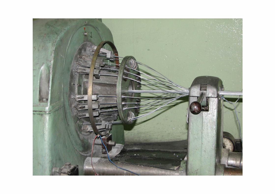
Overhead power line conductors - full cross section or twist (1 or more materials) - ropes Cu, Al, alloys, composites, optical wires, high-temperature
materials - ACSR (Aluminum Conductor Steel Reinforced) = carrying Fe core
+ conductive Al coat 2mm680;180S
- example of labeling 382-AL1/49-ST1A 350AlFe4 AlFe450/52
Rope Construction
Fe Al Rope Nb. of wires
Diameter of wire
Diameter of inner tube
Cross-section
Nb. Of wires
Diameter of wire
Cross-section Diameter Cross-
section RDC+20
ks mm mm mm2 ks mm mm2 mm mm2 ·km-1350 AlFe 4 1+6+12/12+18 19 2,36 11,80 83,11 30 3,75 331,34 26,80 414,45 0,087 450 AlFe 8 3+9/18+14+20 12 2,36 9,90 52,49 18+34 1,90+3,75 426,55 28,70 479,05 0,0674
AlFe 450/52 3+9/12+18+24 12 2,36 9,81 52,49 54 3,25 447,97 29,31 500,46 0,0646 382-AL1/49-ST1A 1+6/12+18+24 7 3,00 3,00 49,48 54 3,00 381,70 27,00 431,18 0,0758 476-AL1/62-ST1A 1+6/12+18+24 7 3,35 10,05 61,70 54 3,35 475,96 30,15 537,66 0,0608


Resistance
Value influenced by: conductor material, temperature, skin effect, elongation due to twisted wires, current density distribution along stripes, sag, unequal cross section, connections
With DC current (at 20C)
)km/(S
R 00dc1
Cu: )m(1078,1 80
Al: )m(1081,2 8
0
Fe: )m(108,12 80
FeAl
FeFeAlAlAlFeDC SS
SS

Temperature effect )()TT()TT(1k 2
0101T Cu: )K(1093,3 13 Al: )K(1003,4 13
Fe: )K(105,4 13 26 K10 → under normal ΔT neglected
Fe
FeFe
Al
AlAl
Fe
Fe
Al
Al
Al
AlFe
Fe
FeAl
Fe
Fe
Al
AlFeAl
SSSS
SSSS
Influence of AC current, e.g. 1
2
0dc12
1212ac m,m,Hz,m,m;
Rrfrr100375,01k

)(3,1004,1kac Empirically by the number of layers Al (Fe core 2÷3% of current)
two layers 04,1kac three layers 06,1kac four layers 05,1kac
In catalogue usually R1dc0 )km/(kkRR acT0dc11
km/2;05,0Rcca 0dc1
AlFe42 R1dc0 ~ 0,7 Ω/km AlFe210 R1dc0 ~ 0,14 Ω/km AlFe70 R1dc0 ~ 0,4 Ω/km AlFe350 R1dc0 ~ 0,09 Ω/km AlFe95 R1dc0 ~ 0,3 Ω/km AlFe450 R1dc0 ~ 0,07 Ω/km AlFe120 R1dc0 ~ 0,2 Ω/km AlFe680 R1dc0 ~ 0,04 Ω/km

Inductance and longitudinal impedance
Inductance and impedance in a loop
,, kkkkIIddldr

Internal inductance of a conductor (magnetic flux inside the conductor)
),,m/H;m/H(8
L rv0ik
17
0 mH104 rv ....... relative permeability of conductor α ......... inequality of current distribution through cross-section
External inductance of a conductor in a loop (magnetic flux outside the conductor)
)m,m,m/H;m/H(rdln
2L 0
ek
Self-inductance
rdln
28LLL 0rv0
ekikv
)m,m;kmmH(r
dlog46,0rdlog46,005,0L 1
rvv

ξ… coefficient of current density inequality in cross section and permeability
46,005,0
10
rv
826,0;809,0 for common ACSR ropes
Impedance of one conductor in a loop of two conductors
16k1kv m
rdlog1046,0jRZ

Self-impedance of a loop conductor-ground - Ground as a conductor of stationary AC current - Rüdenberg’s conception - Density of AC current in a ground is unequal, the maximum is under
the conductor
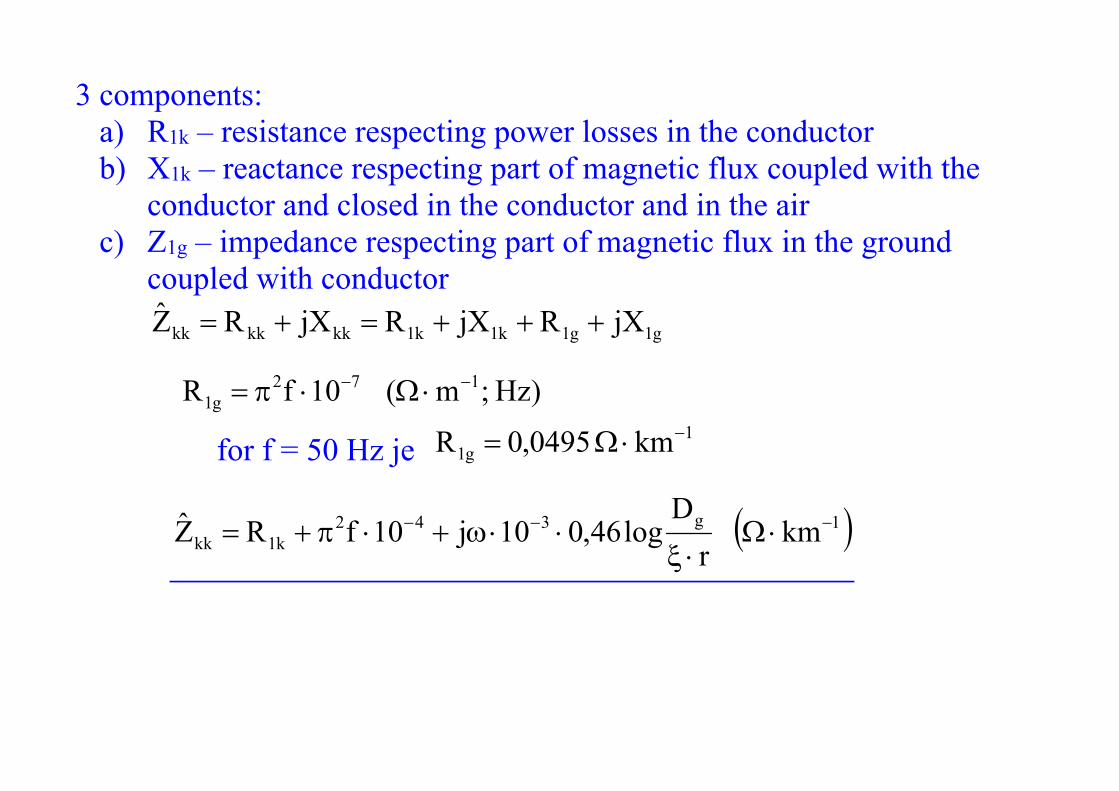
3 components: a) R1k – resistance respecting power losses in the conductor b) X1k – reactance respecting part of magnetic flux coupled with the
conductor and closed in the conductor and in the air c) Z1g – impedance respecting part of magnetic flux in the ground
coupled with conductor g1g1k1k1kkkkkk jXRjXRjXRZ
)Hz;m(10fR 172g1
for f = 50 Hz je
1g1 km0495,0R
1g342k1kk km
rD
log46,010j10fRZ

Fictitious conductor deep in the ground which has the same impacts as the real current in the ground
)Hz,m;m(f
10178,0D
7
g
Dg ~ 100x m, i.e. h<<Dg
ρ…ground resistivity
Type of soil ρ (Ω·m)peat 30 topsoil and clay 100 moist sand 200 - 300 dry gravel and sand 1000 - 3000 stony soil 3000 - 10000

Mutual impedance of two loops conductor-ground - double wire one-phase power line hdkm → return currents are compensated by each other

kmg dD → resulting electromagnetic impacts of return currents in the conductors k´, m´ on the real conductors k, m is almost zero
Impedance of one conductor in a loop mkmkkkkkvkv IZIZIZU
kmkkkvmk ZZZII Hence after substitutions
1g3g1k1kk km
rD
log46,010jRRZ
1km3k1kv km
rdlog1046,0jRZ
1
km
g3g1kvkkkm km
dD
log46,010jRZZZ

Configuration of n real conductors
Configuration of loops n real conductors and the ground is substituted by n real and n fictitious conductors in mutual distance Dg.
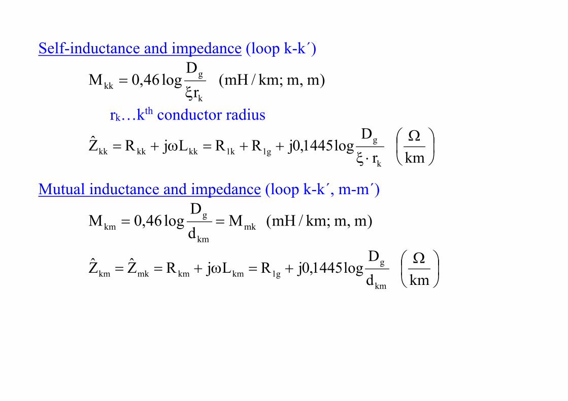
Self-inductance and impedance (loop k-k´)
)m,m;km/mH(r
Dlog46,0M
k
gkk
rk…kth conductor radius
kmrD
log1445,0jRRLjRZk
gg1k1kkkkkk
Mutual inductance and impedance (loop k-k´, m-m´)
)m,m;km/mH(MdD
log46,0M mkkm
gkm
kmd
Dlog1445,0jRLjRZZ
km
gg1kmkmmkkm

Voltage drop in kth conductor
)km/V(IZUn
1mmkmk
(for km is kkk rd ) Operational impedance (inductance) – for 1 single conductor, it causes the same voltage drop as in the system of n conductors (it can be a complex number, done by operating condition)
k
n
1mmkm
kkk
n
1mmkmk I
IZZIZIZU
k
n
1mmkm
k I
IML
n-conductor system ]I][M[j]U[ km

Simple (unbalanced) three-phase power line
Symmetrical loading
ac
a2
b
aa
IaI
IaI
II
0aa1
e23j
21a
e23j
21a
2
32j2
32j

Operational inductances
acab2
aaa
cacbabaaaa MaMaM
IIMIMIML
bc2
bbabb
cbcbbbaabb MaMMa
IIMIMIML
ccbcac2
c
cccbbcaacc MMaMa
IIMIMIML
Generally ccbbaa MMM acbcab MMM
cba LLL → unequal voltage drops (magnitude and phase) → voltage unbalance, active power transfer between phases through electromagnetic coupling without further sources loading → transposition

Transposition of three-phase power line
= conductors position exchange so that each one is in a definite position for 1/3 length
Voltage drops
c
b
a
111312
133323
122322
221223
121113
231333
332313
232212
131211
c
b
a
III
MMMMMMMMM
MMMMMMMMM
MMMMMMMMM
j31
UUU


Let’s mark
)MMM(31M 332211
)MMM(31'M 231312
Then
a
a2a
c
b
a
IaIa
I
M'M'M'MM'M'M'MM
jUUU
Phase operational inductances at transposed and symmetrically loaded power line are equal and real: 'Ma'MaML 2
a 'MMLLL cba

After substitution
)km/mH(r
Dlog46,0M g
)km/mH(d
Dlog46,0'M g
mean geometrical distance 3
231312 dddd
Finally
)km/mH(r
dlog46,0LLLL cba1
kmrdlog1445,0jRZZZ 11

Double power lines with two ground wires
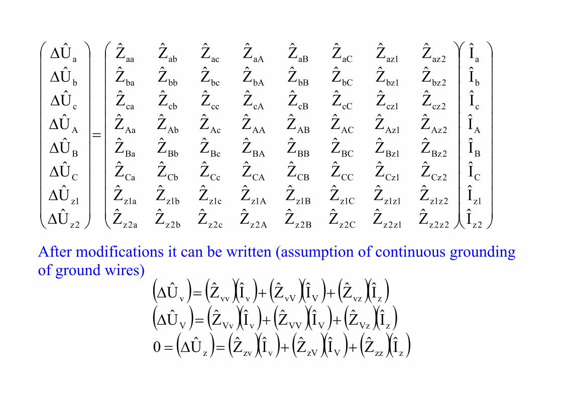
2z
1z
C
B
A
c
b
a
2z2z1z2zC2zB2zA2zc2zb2za2z
2z1z1z1zC1zB1zA1zc1zb1za1z
2Cz1CzCCCBCACcCbCa
2Bz1BzBCBBBABcBbBa
2Az1AzACABAAAcAbAa
2cz1czcCcBcAcccbca
2bz1bzbCbBbAbcbbba
2az1azaCaBaAacabaa
2z
1z
C
B
A
c
b
a
IIIIIIII
ZZZZZZZZZZZZZZZZZZZZZZZZZZZZZZZZZZZZZZZZZZZZZZZZZZZZZZZZZZZZZZZZ
UUUUUUUU
After modifications it can be written (assumption of continuous grounding of ground wires)
zzzVzVvzvz
zVzVVVvVvV
zvzVvVvvvv
IZIZIZU0
IZIZIZU
IZIZIZU

currents in ground wires VzVvzv
1
zzz IZIZZI
For modified power line
VzV
1
zzVzVVvzv
1
zzVzVvV
VzV
1
zzvzvVvzv
1
zzvzvvv
IZZZZIZZZZU
IZZZZIZZZZU
- it is an imaginary power line without ground wires which would act as a real power line with ground wires
- for impedances transfer to symmetrical components system

Power line with bundle conductors
Bundle conductor - each phase composed of n partial conductors connected in parallel - arranged in regular n-polygon - increases initial corona voltage - from voltage 400 kV higher
U (kV) 400 750 1150 1800 n 3 4 8 16
- a400kV = 40 cm

Czech Republic: 400 kV – triple-bundle conductor

Kladno (CR) 110 kV (2), Canada 750 kV (4), China 1000 kV (8)

Operational inductance
)km/mH(r
dlog46,0Lee
1
equivalent bundle radius
n
e RnrRr
equivalent coefficient n
e
→ bundle conductor decreases L, R (conductors in parallel), increases C
22 kV X ~ 0,35 /km 110 kV X ~ 0,35÷0,4 /km 220 kV X ~ 0,4 /km 400 kV X ~ 0,3 /km 750 kV X ~ 0,25 /km

Zero sequence reactance Fe grounding wires - X0 ~ (3,5÷5,5)X1 ACSR grounding wires - X0 ~ (2÷4)X1

Conductance
It causes active power losses by the conductance to the ground (through insulators, corona – dominant at overhead power lines). It depends on voltage, climatic conditions (p, T, humidity), conductors. Less dependant on loading.
Calculation from corona losses 12
12f1SfS kmWUGUG3IU3P
)V,km/W;km/S(UP
G 2S
1 16
118
1 kmS10BxkmS10G
U (kV) G1 (S/km) U (kV) G1 (S/km) 110 (3,6 ÷ 5)·10-8 750 (1,3 ÷ 2,5)·10-8
220 (2,5 ÷ 3,6)·10-8 1150 (1,0 ÷ 2)·10-8 400 (1,4 ÷ 2)·10-8
Recommended