NetSure™ Rectifier User Instructions
UM1R483500E (Issue AE, June 8, 2012)
SPEC. NOS. MODELS
1R483200 R48-3200
1R483200E R48-3200E
(High Efficiency eSure Rectifier)
1R483500E R48-3500E
(High Efficiency eSure Rectifier)
Business-Critical Continuity™, Emerson Network Power, and the Emerson Network Power logo are trademarks and service marks of Emerson Electric Co.
NetSure™, NetSpan™, NetReach™, NetXtend™, and NetPerform™
are trademarks of Emerson Network Power, Energy Systems, North America, Inc.
All other trademarks are the property of their respective owners.
The products covered by this instruction manual are manufactured and/or sold by Emerson Network Power, Energy Systems, North America, Inc.
The information contained in this document is subject to change without notice and may not be suitable for all applications. While every precaution has been taken to ensure the accuracy and completeness of this document, Emerson Network Power, Energy Systems, North America, Inc.
assumes no responsibility and disclaims all liability for damages resulting from use of this information or for any errors or omissions. Refer to other local practices or building codes as applicable for the correct
methods, tools, and materials to be used in performing procedures not specifically described in this document.
This document is the property of Emerson Network Power, Energy Systems, North America, Inc. and contains confidential and proprietary information owned by Emerson Network Power, Energy Systems, North America, Inc. Any copying, use or disclosure of it without the written permission
of Emerson Network Power, Energy Systems, North America, Inc. is strictly prohibited.
Copyright © 2012, Emerson Network Power, Energy Systems, North America, Inc.
All rights reserved throughout the world.
User Instructions UM1R483500E Spec. No. 1R483200 (Model R48-3200) Issue AE, June 8, 2012 Spec. No. 1R483200E (Model R48-3200E) Spec. No. 1R483500E (Model R48-3500E)
Page 1
This document is property of Emerson Network Power, Energy Systems, North America, Inc. and contains confidential and proprietary information owned by Emerson Network Power, Energy Systems, North America, Inc. Any copying, use, or disclosure of it without the written permission of Emerson Network Power, Energy Systems, North America, Inc. is strictly prohibited.
TABLE OF CONTENTS
Introduction .......................................................................................................................... 1
Overview ....................................................................................................................... 1
Specifications ................................................................................................................ 2
Operation ........................................................................................................................... 15
AC Input Protection Device Requirements/Recommendations .................................. 15
Local Indicators ........................................................................................................... 15
Rectifier High Voltage Shutdown and Lockout Restart ............................................... 16
Installing Rectifiers ...................................................................................................... 16
Troubleshooting and Repair .............................................................................................. 17
Troubleshooting .......................................................................................................... 17
Replacement Procedures ........................................................................................... 19
Revision Record ................................................................................................................ 22
INTRODUCTION
Overview
The Rectifiers provide load power, battery float current, and battery recharge current during normal operating conditions. The Rectifiers are a constant power design. This means that, within the normal operating ambient temperature range, the maximum output power available is a constant 3200W or 3500W (depending on Rectifier model). Within this ambient temperature range, the Rectifiers operate in one of three modes, depending upon load demands. Transition between modes is completely automatic.
Constant Voltage Mode: For any initial output voltage setting from 47 to 58 volts, output voltage remains constant regardless of load. This is the normal operating condition, in which loads are being supplied and batteries are float charged. Rectifiers operate in the Constant Voltage Mode unless load increases to the point where the product of load current and output voltage is approximately 3200W or 3500W (depending on Rectifier model).
Constant Power Mode: As load increases above approximately 3200W or 3500W (depending on Rectifier model) (non-adjustable), output current continues to increase, but output voltage decreases as required to maintain constant output power. Rectifiers operate in the Constant Power Mode unless load continues to increase to the point where the current limit setting is reached.
Constant Current Mode: If load increases to the current limit setting, output voltage decreases linearly to maintain output current at the current limit setting.

UM1R483500E User Instructions Issue AE, June 8, 2012 Spec. No. 1R483200 (Model R48-3200)
Spec. No. 1R483200E (Model R48-3200E) Spec. No. 1R483500E (Model R48-3500E)
Page 2
This document is property of Emerson Network Power, Energy Systems, North America, Inc. and contains confidential and proprietary information owned by Emerson Network Power, Energy Systems, North America, Inc. Any copying, use, or disclosure of it without the written permission of Emerson Network Power, Energy Systems, North America, Inc. is strictly prohibited.
Specifications
DC Output Ratings
Voltage: Nominal -48.0 VDC, Positive Ground.
a) Adjustment Range: The output voltage can be set within the range of -47V to -58V, adjustable via the Controller.
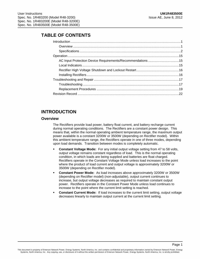
Output Power and Current:
a) Spec. No. 1R483200, Model R48-3200 and Spec. No. 1R483200E, Model R48-3200E: 3200W, maximum (55.2A @ -58 VDC to 66.6A @ -48 VDC).
b) Spec. No. 1R483500E, Model R48-3500E: 3500W, maximum (60.3A @ -58 VDC to 72.9A @ -48 VDC).
c) Refer to Figure 1, Figure 2, and Figure 3 for graphs of rectifier output voltage vs. output current.
Figure 1 Output Voltage vs. Output Current [R48-3200 (1R483200)]
R48-3200 Output Voltage vs. Output Current at Max. Power 3200W
0
10
20
30
40
50
60
0 5 10 15 20 25 30 35 40 45 50 55 60 65 70
For R48-3200 Output Current (A)
Ou
tpu
tV
olt
ag
e(V
)
User Instructions UM1R483500E Spec. No. 1R483200 (Model R48-3200) Issue AE, June 8, 2012 Spec. No. 1R483200E (Model R48-3200E) Spec. No. 1R483500E (Model R48-3500E)
Page 3
This document is property of Emerson Network Power, Energy Systems, North America, Inc. and contains confidential and proprietary information owned by Emerson Network Power, Energy Systems, North America, Inc. Any copying, use, or disclosure of it without the written permission of Emerson Network Power, Energy Systems, North America, Inc. is strictly prohibited.
Figure 2 Output Voltage vs. Output Current [R48-3200E (1R483200E)]
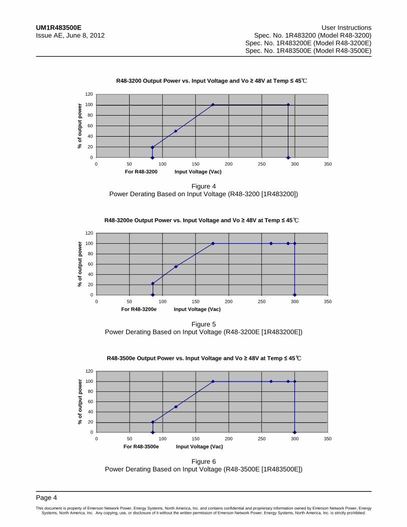
Figure 3 Output Voltage vs. Output Current [R48-3500E (1R483500E)]
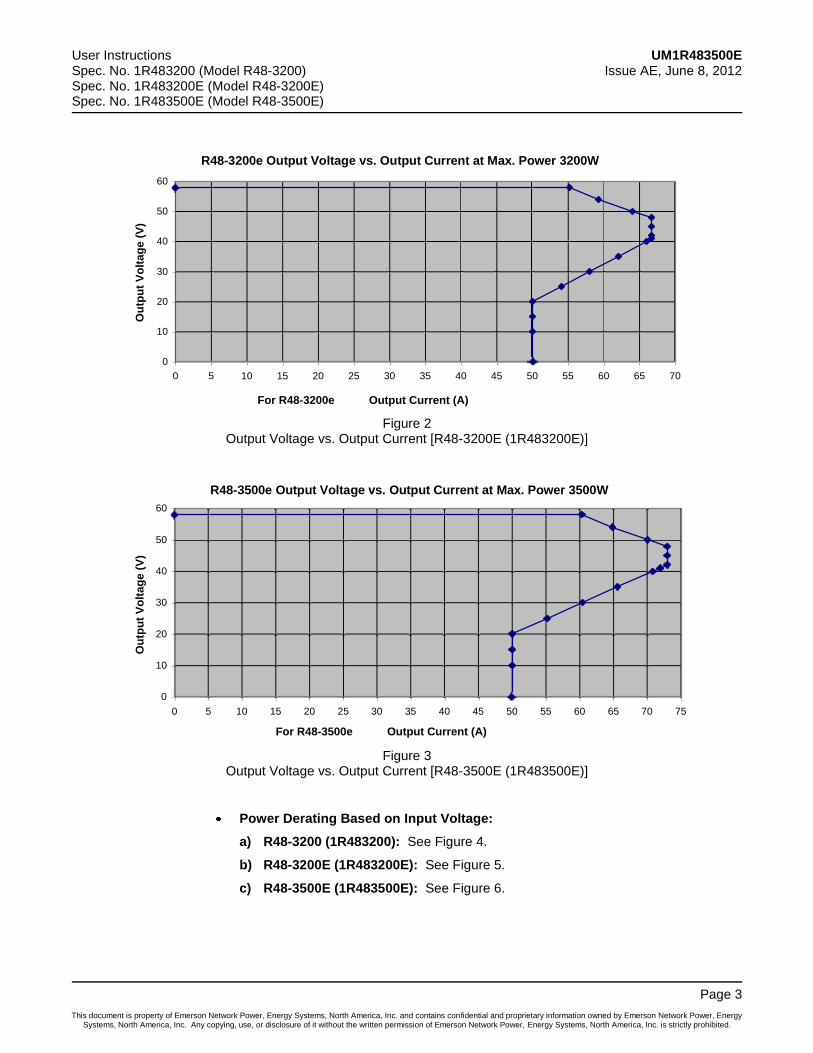
Power Derating Based on Input Voltage:
a) R48-3200 (1R483200): See Figure 4.
b) R48-3200E (1R483200E): See Figure 5.
c) R48-3500E (1R483500E): See Figure 6.
R48-3200e Output Voltage vs. Output Current at Max. Power 3200W
0
10
20
30
40
50
60
0 5 10 15 20 25 30 35 40 45 50 55 60 65 70
For R48-3200e Output Current (A)
Ou
tpu
tV
olt
ag
e(V
)
R48-3500e Output Voltage vs. Output Current at Max. Power 3500W
0
10
20
30
40
50
60
0 5 10 15 20 25 30 35 40 45 50 55 60 65 70 75
For R48-3500e Output Current (A)
Ou
tpu
tV
olt
ag
e(V
)
UM1R483500E User Instructions Issue AE, June 8, 2012 Spec. No. 1R483200 (Model R48-3200)
Spec. No. 1R483200E (Model R48-3200E) Spec. No. 1R483500E (Model R48-3500E)
Page 4
This document is property of Emerson Network Power, Energy Systems, North America, Inc. and contains confidential and proprietary information owned by Emerson Network Power, Energy Systems, North America, Inc. Any copying, use, or disclosure of it without the written permission of Emerson Network Power, Energy Systems, North America, Inc. is strictly prohibited.
Figure 4 Power Derating Based on Input Voltage (R48-3200 [1R483200])
Figure 5 Power Derating Based on Input Voltage (R48-3200E [1R483200E])
Figure 6 Power Derating Based on Input Voltage (R48-3500E [1R483500E])
R48-3200 Output Power vs. Input Voltage and Vo 48V at Temp 45℃
0
20
40
60
80
100
120
0 50 100 150 200 250 300 350
For R48-3200 Input Voltage (Vac)
%o
fo
utp
ut
po
wer
R48-3200e Output Power vs. Input Voltage and Vo 48V at Temp 45℃
0
20
40
60
80
100
120
0 50 100 150 200 250 300 350
For R48-3200e Input Voltage (Vac)
%o
fo
utp
ut
po
wer
R48-3500e Output Power vs. Input Voltage and Vo 48V at Temp 45℃
0
20
40
60
80
100
120
0 50 100 150 200 250 300 350
For R48-3500e Input Voltage (Vac)
%o
fo
utp
ut
po
wer
User Instructions UM1R483500E Spec. No. 1R483200 (Model R48-3200) Issue AE, June 8, 2012 Spec. No. 1R483200E (Model R48-3200E) Spec. No. 1R483500E (Model R48-3500E)
Page 5
This document is property of Emerson Network Power, Energy Systems, North America, Inc. and contains confidential and proprietary information owned by Emerson Network Power, Energy Systems, North America, Inc. Any copying, use, or disclosure of it without the written permission of Emerson Network Power, Energy Systems, North America, Inc. is strictly prohibited.
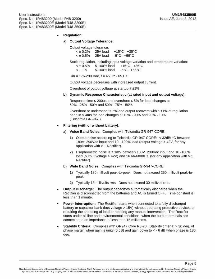
Regulation:
a) Output Voltage Tolerance:
Output voltage tolerance: < ± 0.2% 25A load +15°C - +35°C < ± 0.5% 25A load -5°C - +55°C
Static regulation, including input voltage variation and temperature variation: < ± 0.5% 5-100% load +15°C - +35°C < ± 1% 5-100% load -5°C - +55°C
Uin = 176-290 Vac, f = 45 Hz - 65 Hz
Output voltage decreases with increased output current.
Overshoot of output voltage at startup ≤ ±1%.
b) Dynamic Response Characteristic (at rated input and output voltage):
Response time ≤ 200us and overshoot ≤ 5% for load changes at 50% - 25% - 50% and 50% - 75% - 50%.
Overshoot or undershoot ≤ 5% and output recovers within ±1% of regulation band in ≤ 4ms for load changes at 10% - 90% and 90% - 10%. (Telcordia GR-947.)
Filtering (with or without battery):
a) Voice Band Noise: Complies with Telcordia GR-947-CORE.
1) Output noise according to Telcordia GR-947-CORE: < 32dBrnC between 180V~290Vac input and 10 - 100% load (output voltage > 42V, for any application with > 1 Rectifier).
2) Psophometric noise is ≤ 1mV between 180V~290Vac input and 10 -100% load (output voltage > 42V) and 16.66-6000Hz. (for any application with > 1 Rectifier).
b) Wide Band Noise: Complies with Telcordia GR-947-CORE.
1) Typically 130 millivolt peak-to-peak. Does not exceed 250 millivolt peak-to-peak.
2) Typically 13 millivolts rms. Does not exceed 30 millivolt rms.
Output Discharge: The output capacitors automatically discharge when the Rectifier is disconnected from the batteries and AC is turned OFF. Time constant is less than 1 minute.
Power Interruption: The Rectifier starts when connected to a fully discharged battery or capacitor bank (bus voltage > 15V) without operating protective devices or requiring the shedding of load or needing any manual intervention. The Rectifier starts under all line and environmental conditions, when the output terminals are connected to an impedance of less than 15 milliohms.
Stability Criteria: Complies with GR947 Core R3-20. Stability criteria: > 30 deg. of phase margin when gain is unity (0 dB) and gain down to < - 6 dB when phase is 180 deg.
UM1R483500E User Instructions Issue AE, June 8, 2012 Spec. No. 1R483200 (Model R48-3200)
Spec. No. 1R483200E (Model R48-3200E) Spec. No. 1R483500E (Model R48-3500E)
Page 6
This document is property of Emerson Network Power, Energy Systems, North America, Inc. and contains confidential and proprietary information owned by Emerson Network Power, Energy Systems, North America, Inc. Any copying, use, or disclosure of it without the written permission of Emerson Network Power, Energy Systems, North America, Inc. is strictly prohibited.
AC Input Ratings
Voltage: Nominal 208/240 volts AC, single phase, 50/60 Hz, with an operating range of 176 to 264 volts. Acceptable input frequency range is 45 to 65 Hz.
Safe Voltage: The system can tolerate 415 volts AC without damage.
Harmonic Content (THD): < 5% THD at 50% - 100% load. The voltage source must have a voltage THD of < 1.1%.
The Rectifier complies with EN61000-3-2.
Inrush Current: Peak does not exceed 1.5 times the steady state peak value of the input current at full load, nominal input voltage, and for any duration of AC input interrupts. Under the above conditions, standard AC distribution circuit breakers will not trip.
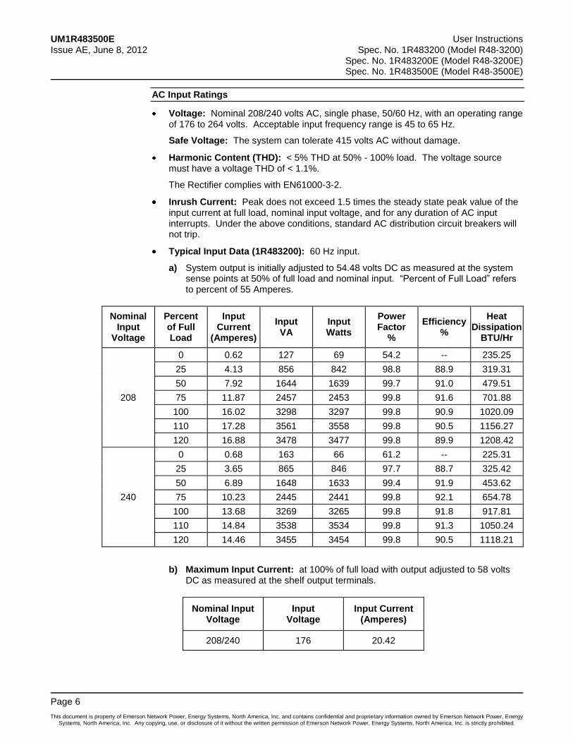
Typical Input Data (1R483200): 60 Hz input.
a) System output is initially adjusted to 54.48 volts DC as measured at the system sense points at 50% of full load and nominal input. “Percent of Full Load” refers to percent of 55 Amperes.
Nominal Input
Voltage
Percent of Full Load
Input Current
(Amperes)
Input VA
Input Watts
Power Factor
%
Efficiency %
Heat Dissipation
BTU/Hr
208
0 0.62 127 69 54.2 -- 235.25
25 4.13 856 842 98.8 88.9 319.31
50 7.92 1644 1639 99.7 91.0 479.51
75 11.87 2457 2453 99.8 91.6 701.88
100 16.02 3298 3297 99.8 90.9 1020.09
110 17.28 3561 3558 99.8 90.5 1156.27
120 16.88 3478 3477 99.8 89.9 1208.42
240
0 0.68 163 66 61.2 -- 225.31
25 3.65 865 846 97.7 88.7 325.42
50 6.89 1648 1633 99.4 91.9 453.62
75 10.23 2445 2441 99.8 92.1 654.78
100 13.68 3269 3265 99.8 91.8 917.81
110 14.84 3538 3534 99.8 91.3 1050.24
120 14.46 3455 3454 99.8 90.5 1118.21
b) Maximum Input Current: at 100% of full load with output adjusted to 58 volts DC as measured at the shelf output terminals.
Nominal Input Voltage
Input Voltage
Input Current (Amperes)
208/240 176 20.42
User Instructions UM1R483500E Spec. No. 1R483200 (Model R48-3200) Issue AE, June 8, 2012 Spec. No. 1R483200E (Model R48-3200E) Spec. No. 1R483500E (Model R48-3500E)
Page 7
This document is property of Emerson Network Power, Energy Systems, North America, Inc. and contains confidential and proprietary information owned by Emerson Network Power, Energy Systems, North America, Inc. Any copying, use, or disclosure of it without the written permission of Emerson Network Power, Energy Systems, North America, Inc. is strictly prohibited.
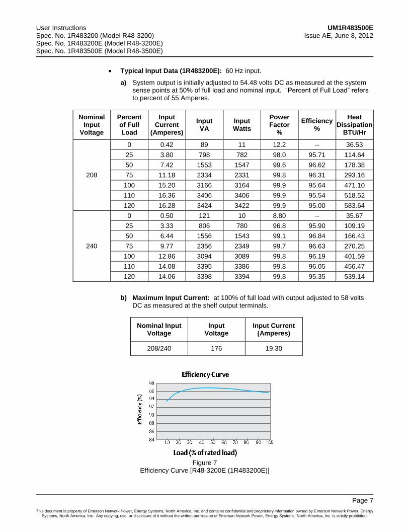
Typical Input Data (1R483200E): 60 Hz input.
a) System output is initially adjusted to 54.48 volts DC as measured at the system sense points at 50% of full load and nominal input. “Percent of Full Load” refers to percent of 55 Amperes.
Nominal Input
Voltage
Percent of Full Load
Input Current
(Amperes)
Input VA
Input Watts
Power Factor
%
Efficiency %
Heat Dissipation
BTU/Hr
208
0 0.42 89 11 12.2 -- 36.53
25 3.80 798 782 98.0 95.71 114.64
50 7.42 1553 1547 99.6 96.62 178.38
75 11.18 2334 2331 99.8 96.31 293.16
100 15.20 3166 3164 99.9 95.64 471.10
110 16.36 3406 3406 99.9 95.54 518.52
120 16.28 3424 3422 99.9 95.00 583.64
240
0 0.50 121 10 8.80 -- 35.67
25 3.33 806 780 96.8 95.90 109.19
50 6.44 1556 1543 99.1 96.84 166.43
75 9.77 2356 2349 99.7 96.63 270.25
100 12.86 3094 3089 99.8 96.19 401.59
110 14.08 3395 3386 99.8 96.05 456.47
120 14.06 3398 3394 99.8 95.35 539.14
b) Maximum Input Current: at 100% of full load with output adjusted to 58 volts DC as measured at the shelf output terminals.
Nominal Input Voltage
Input Voltage
Input Current (Amperes)
208/240 176 19.30
Figure 7 Efficiency Curve [R48-3200E (1R483200E)]
UM1R483500E User Instructions Issue AE, June 8, 2012 Spec. No. 1R483200 (Model R48-3200)
Spec. No. 1R483200E (Model R48-3200E) Spec. No. 1R483500E (Model R48-3500E)
Page 8
This document is property of Emerson Network Power, Energy Systems, North America, Inc. and contains confidential and proprietary information owned by Emerson Network Power, Energy Systems, North America, Inc. Any copying, use, or disclosure of it without the written permission of Emerson Network Power, Energy Systems, North America, Inc. is strictly prohibited.
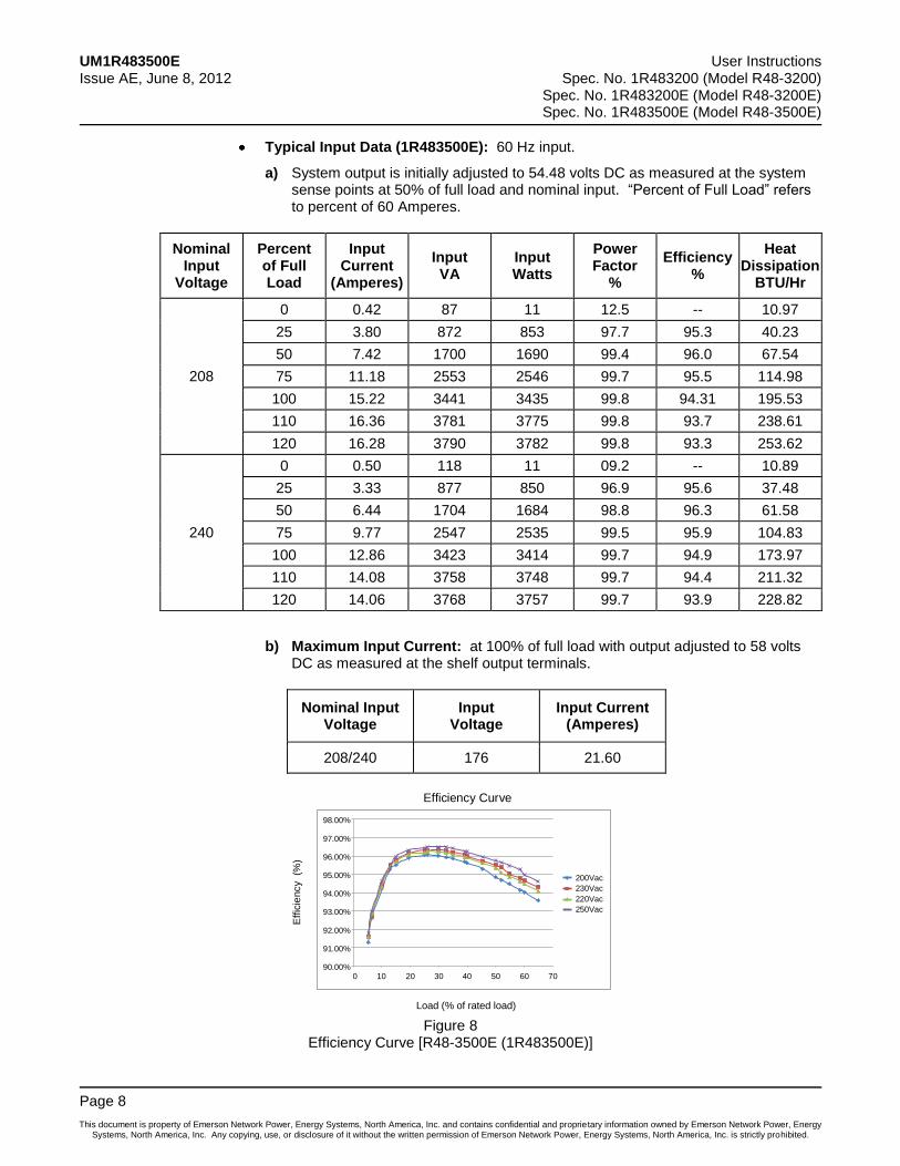
Typical Input Data (1R483500E): 60 Hz input.
a) System output is initially adjusted to 54.48 volts DC as measured at the system sense points at 50% of full load and nominal input. “Percent of Full Load” refers to percent of 60 Amperes.
Nominal Input
Voltage
Percent of Full Load
Input Current
(Amperes)
Input VA
Input Watts
Power Factor
%
Efficiency %
Heat Dissipation
BTU/Hr
208
0 0.42 87 11 12.5 -- 10.97
25 3.80 872 853 97.7 95.3 40.23
50 7.42 1700 1690 99.4 96.0 67.54
75 11.18 2553 2546 99.7 95.5 114.98
100 15.22 3441 3435 99.8 94.31 195.53
110 16.36 3781 3775 99.8 93.7 238.61
120 16.28 3790 3782 99.8 93.3 253.62
240
0 0.50 118 11 09.2 -- 10.89
25 3.33 877 850 96.9 95.6 37.48
50 6.44 1704 1684 98.8 96.3 61.58
75 9.77 2547 2535 99.5 95.9 104.83
100 12.86 3423 3414 99.7 94.9 173.97
110 14.08 3758 3748 99.7 94.4 211.32
120 14.06 3768 3757 99.7 93.9 228.82
b) Maximum Input Current: at 100% of full load with output adjusted to 58 volts DC as measured at the shelf output terminals.
Nominal Input Voltage
Input Voltage
Input Current (Amperes)
208/240 176 21.60
Figure 8 Efficiency Curve [R48-3500E (1R483500E)]
Efficiency Curve
Load (% of rated load)
Effic
iency
(%)
90.00%
91.00%
92.00%
93.00%
94.00%
95.00%
96.00%
97.00%
98.00%
0 10 20 30 40 50 60 70
200Vac
230Vac
220Vac
250Vac
User Instructions UM1R483500E Spec. No. 1R483200 (Model R48-3200) Issue AE, June 8, 2012 Spec. No. 1R483200E (Model R48-3200E) Spec. No. 1R483500E (Model R48-3500E)
Page 9
This document is property of Emerson Network Power, Energy Systems, North America, Inc. and contains confidential and proprietary information owned by Emerson Network Power, Energy Systems, North America, Inc. Any copying, use, or disclosure of it without the written permission of Emerson Network Power, Energy Systems, North America, Inc. is strictly prohibited.
Environmental Ratings
Climatic and Mechanical Environment:
Meets ETS 300 019-1-2, class 2.3.
Storage and handling: ETS 300 019-1-1, class 1.2.
Operation: ETS 300 019-1-3, class 3.2.
Transportation, storage and handling, operation: Telcordia GR-63-Core, chapter 4.
Earthquake: Telcordia GR-63-Core, Zone-4.
The Rectifier operates in an extended temperature with output derating according to Figure 9, Figure 10, and Figure 11.
Relative Humidity: ≤95% (no condensation).
a) Temperature:
1) Temperature:
-40 to +75 degrees C, operating temperature range.
-40 to +45 degrees C with 3200W or 3500W output (depends on rectifier module), +45 to +75 degrees C with derated output per Figure 9, Figure 10, and Figure 11.
-20 to +45 degrees C with full performance.
Rectifier starts at -40 degrees C, and continuously operates.
At fan failure the Rectifier shuts down. Does not rely on the temperature sensors.
2) Temperature Coefficient: 0.01% per degrees Celsius.
b) Dust Filter: No dust filter is used.
c) Airborne Contaminant: Erosion-proof coating is used on PCB boards.
1) Gas Contaminant Test (Corrosion Air): The Rectifier works normally in corrosion air condition according to Telcordia, GR63 ch. 4.5 and 5.5.3. Also complies with NEBS requirement of gas contaminant.
2) Hygroscopic Dust: Complies with NEBS requirement of hygroscopic dust.
d) Altitude (Air Pressure):
1) The maximum operating ambient temperature should be derated above altitude of 2000m.
2) Meets NEBS requirement of altitude per Telcordia GR-63-Core.
e) Office Vibration: Meets NEBS requirement of office vibration per Telcordia GR-63-Core.
f) Illumination: Meets NEBS requirement of illumination per Telcordia GR-63-Core.
Ventilation Requirements: The Rectifiers are fan cooled and utilize front to back forced ventilation. A Rectifier must be mounted so ventilating openings are not blocked and temperature of the air entering the Rectifier does not exceed the Operating Ambient Temperature Range stated above.
UM1R483500E User Instructions Issue AE, June 8, 2012 Spec. No. 1R483200 (Model R48-3200)
Spec. No. 1R483200E (Model R48-3200E) Spec. No. 1R483500E (Model R48-3500E)
Page 10
This document is property of Emerson Network Power, Energy Systems, North America, Inc. and contains confidential and proprietary information owned by Emerson Network Power, Energy Systems, North America, Inc. Any copying, use, or disclosure of it without the written permission of Emerson Network Power, Energy Systems, North America, Inc. is strictly prohibited.
Single Rectifier Audible Noise:
a) At 25°C ≤ 53dB(A) with fan in high speed; Measurement made at 0.6m distance in front of Rectifier and at same horizontal line of the middle of Rectifier.
b) At 25°C ≤ 45dB(A) with fan in low speed; Measurement made at 1m distance in front of Rectifier and at same horizontal line of the middle of Rectifier.
EMI/RFI Suppression:
a) Rectifiers operating in an approved Rectifier Mounting Shelf conform to the requirements of FCC rules Part 15, Subpart B, Class B for Radiated and Conducted emissions limits.
b) Rectifiers operating in an approved Rectifier Mounting Shelf conform to the requirements of European Norm, EN55022, Class B for Radiated and Conducted emissions limits.
Surge Protection: Compliance with EN61000-4-5 Installation Class 4, and capable of withstanding surges per ANSI/IEEE C 62.41 1980 Category B3 across the input terminals.
Note: This level of protection is a widely used standard for telecommunications power equipment. As with all such equipment, it is the end user's responsibility to provide an adequately sized Surge Suppression Device at the commercial power service entrance of the building that reduces all incoming surges to levels below the classes/categories stated for the equipment.
Compliance Information:
a) Safety Compliance: This unit meets the requirements of UL 60950-1, Standard for Information Technology Equipment, and is UL Recognized as a power supply for use in Telephone, Electronic Data Processing or Information Processing Equipment. This unit meets the requirements of CAN/CSA 22.2, No. 60950-00 and is tested and Certified by UL ("c UR")as a Component Type Power Supply.
b) The Rectifiers are RoHS compliant, 5/6.
ESD Protection: Meets EN 61000-4-2.
a) Requirements are 6kV contact and 8kV air for criteria B and 8kV/15kV for criteria C.
b) According Telcordia GR-1089-CORE R2-1, R2-2, R2-3, O2-4.
Electrical Fast Transient / Burst Immunity
a) Meets EN 61000-4-4:
1) Burst will be fulfilled for AC and DC terminals at 4kV with criteria B.
2) Burst will be fulfilled CAN-bus signals at 1kV with criteria B.
b) Meets GR-1089 O2-8:
1) Burst (EFT) will be fulfilled for AC and DC terminals at 0.5kV.
2) Burst will be fulfilled CAN-bus signals at 0.25kV.
User Instructions UM1R483500E Spec. No. 1R483200 (Model R48-3200) Issue AE, June 8, 2012 Spec. No. 1R483200E (Model R48-3200E) Spec. No. 1R483500E (Model R48-3500E)
Page 11
This document is property of Emerson Network Power, Energy Systems, North America, Inc. and contains confidential and proprietary information owned by Emerson Network Power, Energy Systems, North America, Inc. Any copying, use, or disclosure of it without the written permission of Emerson Network Power, Energy Systems, North America, Inc. is strictly prohibited.
Standard Features
Type of Power Conversion Circuit: High frequency.
Constant Voltage Mode: For any initial output voltage setting from 47 to 58 volts, output voltage remains constant regardless of load. This is the normal operating condition, in which loads are being supplied and batteries are float charged. Rectifiers operate in the Constant Voltage Mode unless load increases to the point where the product of load current and output voltage is approximately 3200W or 3500W (depending on Rectifier model).
Constant Power Mode: As load increases above approximately 3200W or 3500W (depending on Rectifier model) (non-adjustable), output current continues to increase, but output voltage decreases as required to maintain constant output power. Rectifiers operate in the Constant Power Mode unless load continues to increase to the point where the current limit setting is reached.
Constant Current Mode: If load increases to the current limit setting, output voltage decreases linearly to maintain output current at the current limit setting.
Input Protection:
a) Fuse: On the input, two UL recognized fuses are used, not user-replaceable.
b) Input Voltage Protection: Operating range is 85-290Vac. Derating from 85Vac to 176Vac. Withstand 415Vac input w/o damage.
1) The Rectifier will shut down at low or high voltage input; Low voltage disable point: 80V±3V; Hysteresis at least 15 VAC for restart. High voltage disable point: 295V±5V; Hysteresis at least 10 VAC for restart.
2) Between 85V and 176V the output power will be derated linearly according to input voltage per Figure 4, Figure 5, and Figure 6.
3) Over Voltage Isolation: The Rectifier will be disconnected from the AC input when a preset non-adjustable value is reached.
AC Fail Alarm: The Rectifier issues an "AC Fail Alarm" when AC input voltage drops below 164Vac. This alarm clears when AC input voltage recovers above 169Vac.
Output Protection:
a) Current Limiting: The maximum current delivered by the rectifier can be set via the Controller from 10% to 121% of its rating at maximum rated output voltage. Output Current Limit Error: ≤ ±1.5A.
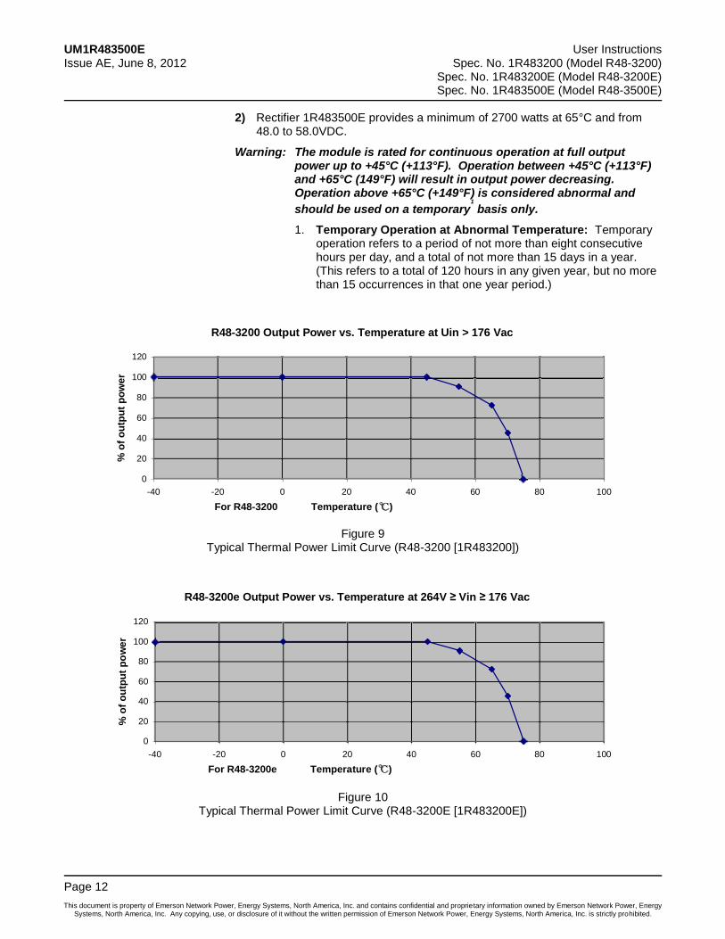
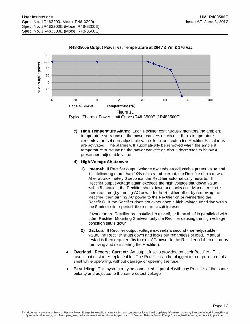
b) Thermal Power Limiting: Each Rectifier continuously monitors the ambient temperature surrounding the power conversion circuit. If this temperature for any reason (such as a high ambient temperature) increases above approximately +45°C (+113°F), the Rectifier will not shut down. Rather, the Rectifier will limit its maximum output power to maintain the temperature of the power conversion circuit within design parameters. Operation between +45°C (+113°F) and +65°C (149°F) will result in the output power being decreased. Full power capability is restored when the temperature decreases to below approximately +45°C (+113°F). Refer to the following curves (Figure 9, Figure 10, and Figure 11) illustrating typical operating parameters.
1) Rectifiers 1R483200 and 1R483200E provide a minimum of 2320 watts at 65°C and from 48.0 to 58.0VDC.
UM1R483500E User Instructions Issue AE, June 8, 2012 Spec. No. 1R483200 (Model R48-3200)
Spec. No. 1R483200E (Model R48-3200E) Spec. No. 1R483500E (Model R48-3500E)
Page 12
This document is property of Emerson Network Power, Energy Systems, North America, Inc. and contains confidential and proprietary information owned by Emerson Network Power, Energy Systems, North America, Inc. Any copying, use, or disclosure of it without the written permission of Emerson Network Power, Energy Systems, North America, Inc. is strictly prohibited.
2) Rectifier 1R483500E provides a minimum of 2700 watts at 65°C and from 48.0 to 58.0VDC.
Warning: The module is rated for continuous operation at full output power up to +45°C (+113°F). Operation between +45°C (+113°F) and +65°C (149°F) will result in output power decreasing. Operation above +65°C (+149°F) is considered abnormal and
should be used on a temporary1
basis only.
1. Temporary Operation at Abnormal Temperature: Temporary operation refers to a period of not more than eight consecutive hours per day, and a total of not more than 15 days in a year. (This refers to a total of 120 hours in any given year, but no more than 15 occurrences in that one year period.)
Figure 9 Typical Thermal Power Limit Curve (R48-3200 [1R483200])
Figure 10 Typical Thermal Power Limit Curve (R48-3200E [1R483200E])
R48-3200 Output Power vs. Temperature at Uin > 176 Vac
0
20
40
60
80
100
120
-40 -20 0 20 40 60 80 100
For R48-3200 Temperature (℃)
%o
fo
utp
ut
po
wer
R48-3200e Output Power vs. Temperature at 264V Vin 176 Vac
0
20
40
60
80
100
120
-40 -20 0 20 40 60 80 100
For R48-3200e Temperature (℃)
%o
fo
utp
ut
po
we
r
User Instructions UM1R483500E Spec. No. 1R483200 (Model R48-3200) Issue AE, June 8, 2012 Spec. No. 1R483200E (Model R48-3200E) Spec. No. 1R483500E (Model R48-3500E)
Page 13
This document is property of Emerson Network Power, Energy Systems, North America, Inc. and contains confidential and proprietary information owned by Emerson Network Power, Energy Systems, North America, Inc. Any copying, use, or disclosure of it without the written permission of Emerson Network Power, Energy Systems, North America, Inc. is strictly prohibited.
Figure 11 Typical Thermal Power Limit Curve (R48-3500E [1R483500E])
c) High Temperature Alarm: Each Rectifier continuously monitors the ambient temperature surrounding the power conversion circuit. If this temperature exceeds a preset non-adjustable value, local and extended Rectifier Fail alarms are activated. The alarms will automatically be removed when the ambient temperature surrounding the power conversion circuit decreases to below a preset non-adjustable value.
d) High Voltage Shutdown:
1) Internal: If Rectifier output voltage exceeds an adjustable preset value and it is delivering more than 10% of its rated current, the Rectifier shuts down. After approximately 6 seconds, the Rectifier automatically restarts. If Rectifier output voltage again exceeds the high voltage shutdown value within 5 minutes, the Rectifier shuts down and locks out. Manual restart is then required (by turning AC power to the Rectifier off or by removing the Rectifier, then turning AC power to the Rectifier on or reinserting the Rectifier). If the Rectifier does not experience a high voltage condition within the 5-minute time-period, the restart circuit is reset.
If two or more Rectifier are installed in a shelf, or if the shelf is paralleled with other Rectifier Mounting Shelves, only the Rectifier causing the high voltage condition shuts down.
2) Backup: If Rectifier output voltage exceeds a second (non-adjustable) value, the Rectifier shuts down and locks out regardless of load. Manual restart is then required (by turning AC power to the Rectifier off then on, or by removing and re-inserting the Rectifier).
Overload / Reverse Current: An output fuse is provided on each Rectifier. This fuse is not customer replaceable. The Rectifier can be plugged into or pulled out of a shelf while operating, without damage or opening the fuse.
Paralleling: This system may be connected in parallel with any Rectifier of the same polarity and adjusted to the same output voltage.
For R48-3500e Temperature (°C)
0
20
40
60
80
100
120
-40 -20 0 20 40 60 80 100
%o
fo
utp
ut
po
we
r
R48-3500e Output Power vs. Temperature at 264V Vin 176 Vac
UM1R483500E User Instructions Issue AE, June 8, 2012 Spec. No. 1R483200 (Model R48-3200)
Spec. No. 1R483200E (Model R48-3200E) Spec. No. 1R483500E (Model R48-3500E)
Page 14
This document is property of Emerson Network Power, Energy Systems, North America, Inc. and contains confidential and proprietary information owned by Emerson Network Power, Energy Systems, North America, Inc. Any copying, use, or disclosure of it without the written permission of Emerson Network Power, Energy Systems, North America, Inc. is strictly prohibited.
Output Current Walk-In:
a) Normal Start:
Start up time, defined as beginning at AC switch on and ending when full output power has been reached, consists of two time intervals, the delay period and the output voltage rampup period.
During the delay period the output voltage will be zero.
Start up time (AC on, till full power): ≤ 5 seconds.
Output voltage ramp up period, t: 50 ≤ t ≤ 150 ms. (10% to 90% of full power)
The Rectifier will not suffer any damage, when subjected to repetitive AC switch on / switch off operations.
b) Current Walk-In (if enabled via Controller):
90% load in > 8S, 100% load in < 124s.
According to Telcordia GR-947-CORE, R3-19.
Cooling: Front-to-back force air-cooling.
Fan Control:
When input voltage is within normal range, the fan’s speed is controlled based on the Rectifier's internal temperature.
The fan is turned off when input voltage is abnormal such as very low or high input voltage.
The fan starts at half speed when the Rectifier starts up.
A fan failure is detected and reported to Controller.
Full fan speed is customer selectable via the Controller.
Communication Failure: The Rectifier’s protection indicator (yellow) will flash should it experience a communication failure. The failure information will be reported to the Controller and the Controller will process the failure accordingly. During a communication failure, in order to protect the battery, the Rectifier output voltage will automatically be adjusted as follows. When used with the SCU+ Controller, Rectifier output voltage goes to a default value (53.5 V, which can be modified using the SCU+ Controller). When used with the ACU+ Controller, Rectifier output voltage goes to the ACU+ float voltage setting (this setting is stored in the Rectifier). The Rectifier will revert to normal operation once normal communication is restored.
External Control Circuits: Provided via the associated Controller. Refer to the separate Power System documentation for a complete description of available external control circuits.
External Alarm Circuits: Provided via the associated Controller. Refer to the separate Power System documentation for a description of available external alarms.
Dimensions:
a) Millimeters: 132.0 (Height) X 85.3 (Width) X 287.0 (Depth)
b) Inches: 5.2 (Height) X 3.36 (Width) X 11.3 (Depth)
Weight: 3.5 kg (7.7 lbs).
User Instructions UM1R483500E Spec. No. 1R483200 (Model R48-3200) Issue AE, June 8, 2012 Spec. No. 1R483200E (Model R48-3200E) Spec. No. 1R483500E (Model R48-3500E)
Page 15
This document is property of Emerson Network Power, Energy Systems, North America, Inc. and contains confidential and proprietary information owned by Emerson Network Power, Energy Systems, North America, Inc. Any copying, use, or disclosure of it without the written permission of Emerson Network Power, Energy Systems, North America, Inc. is strictly prohibited.
OPERATION
AC Input Protection Device Requirements/Recommendations
Refer to the system documentation supplied with the system the rectifier is installed in.
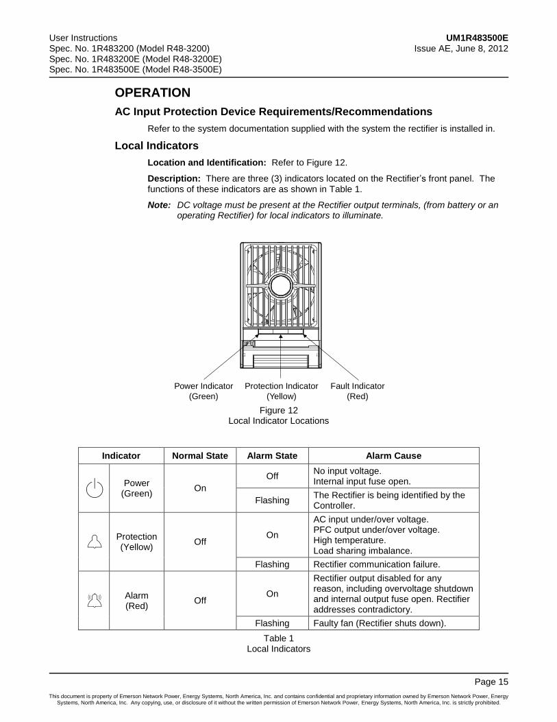
Local Indicators
Location and Identification: Refer to Figure 12.
Description: There are three (3) indicators located on the Rectifier’s front panel. The functions of these indicators are as shown in Table 1.
Note: DC voltage must be present at the Rectifier output terminals, (from battery or an operating Rectifier) for local indicators to illuminate.
Figure 12 Local Indicator Locations
Indicator Normal State Alarm State Alarm Cause
Power (Green)
On
Off No input voltage. Internal input fuse open.
Flashing The Rectifier is being identified by the Controller.
Protection (Yellow)
Off On
AC input under/over voltage. PFC output under/over voltage. High temperature. Load sharing imbalance.
Flashing Rectifier communication failure.
Alarm (Red)
Off On
Rectifier output disabled for any reason, including overvoltage shutdown and internal output fuse open. Rectifier addresses contradictory.
Flashing Faulty fan (Rectifier shuts down).
Table 1 Local Indicators
Power Indicator
(Green)
Protection Indicator
(Yellow)
Fault Indicator
(Red)
UM1R483500E User Instructions Issue AE, June 8, 2012 Spec. No. 1R483200 (Model R48-3200)
Spec. No. 1R483200E (Model R48-3200E) Spec. No. 1R483500E (Model R48-3500E)
Page 16
This document is property of Emerson Network Power, Energy Systems, North America, Inc. and contains confidential and proprietary information owned by Emerson Network Power, Energy Systems, North America, Inc. Any copying, use, or disclosure of it without the written permission of Emerson Network Power, Energy Systems, North America, Inc. is strictly prohibited.
Rectifier High Voltage Shutdown and Lockout Restart
Turn AC power to the Rectifier OFF or remove the Rectifier, wait 30 seconds or more, then turn AC power to the Rectifier ON or re-insert the Rectifier.
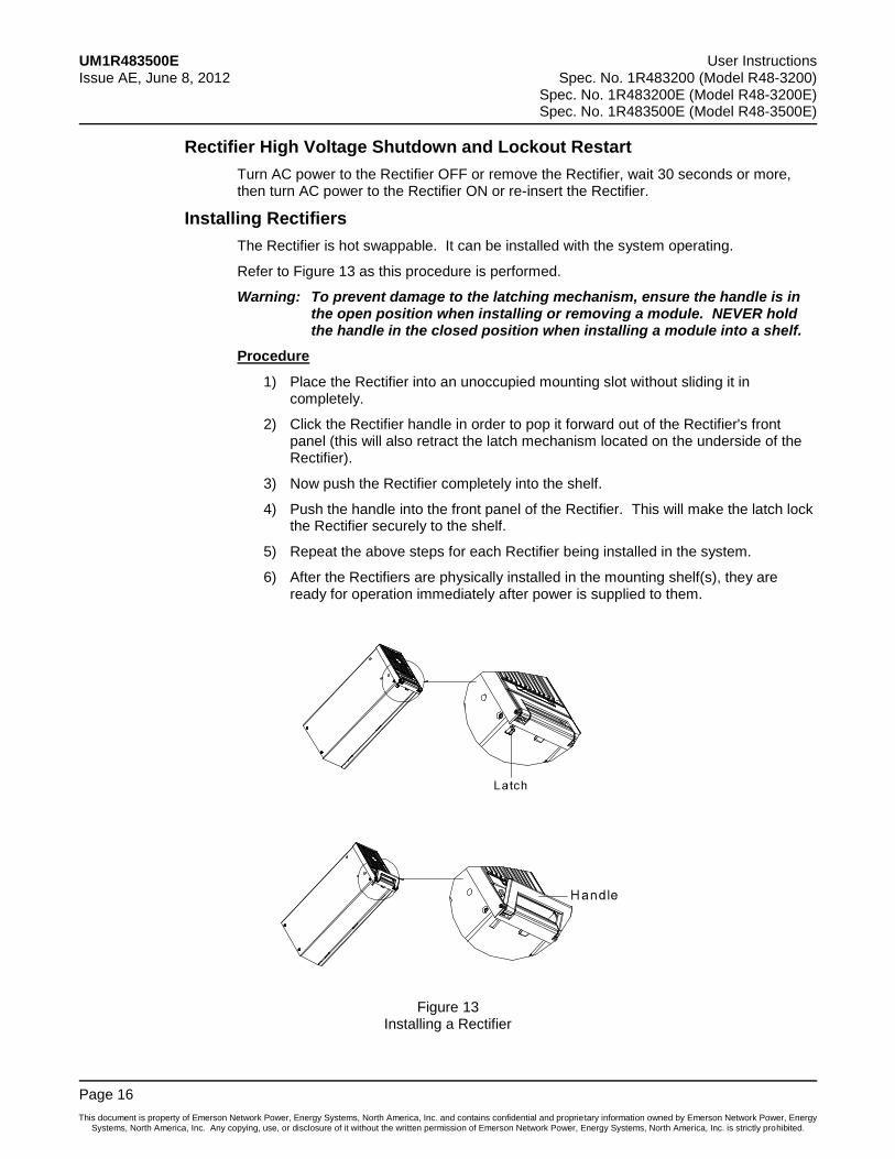
Installing Rectifiers
The Rectifier is hot swappable. It can be installed with the system operating.
Refer to Figure 13 as this procedure is performed.
Warning: To prevent damage to the latching mechanism, ensure the handle is in the open position when installing or removing a module. NEVER hold the handle in the closed position when installing a module into a shelf.
Procedure
1) Place the Rectifier into an unoccupied mounting slot without sliding it in completely.
2) Click the Rectifier handle in order to pop it forward out of the Rectifier's front panel (this will also retract the latch mechanism located on the underside of the Rectifier).
3) Now push the Rectifier completely into the shelf.
4) Push the handle into the front panel of the Rectifier. This will make the latch lock the Rectifier securely to the shelf.
5) Repeat the above steps for each Rectifier being installed in the system.
6) After the Rectifiers are physically installed in the mounting shelf(s), they are ready for operation immediately after power is supplied to them.
Figure 13 Installing a Rectifier
User Instructions UM1R483500E Spec. No. 1R483200 (Model R48-3200) Issue AE, June 8, 2012 Spec. No. 1R483200E (Model R48-3200E) Spec. No. 1R483500E (Model R48-3500E)
Page 17
This document is property of Emerson Network Power, Energy Systems, North America, Inc. and contains confidential and proprietary information owned by Emerson Network Power, Energy Systems, North America, Inc. Any copying, use, or disclosure of it without the written permission of Emerson Network Power, Energy Systems, North America, Inc. is strictly prohibited.
TROUBLESHOOTING AND REPAIR
Troubleshooting
Rectifier Imbalanced Current Sharing
When multiple Rectifiers are operating in parallel and the current sharing imbalance among them is greater than 3%, check if the Rectifier is properly seated in the shelf.
If the current sharing imbalance still persists following the verification suggested above, replace the Rectifier exhibiting the current imbalance.
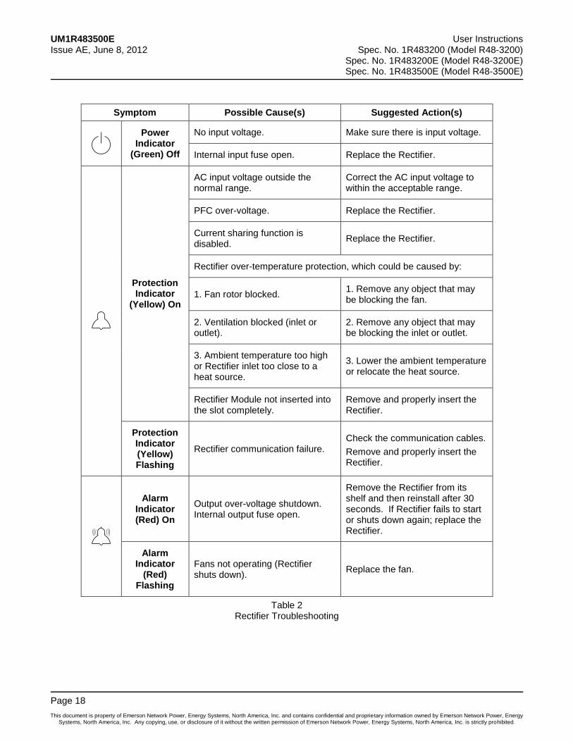
Rectifier Fault Symptoms and Troubleshooting
The fault indicators that can be displayed by the Rectifier are as follows: Power indicator (green) OFF, Protection indicator (yellow) ON, Protection indicator (yellow) flashing, Alarm indicator (red) ON, and Alarm indicator (red) flashing. Refer to Table 2 for a list of possible causes and corrective actions.
UM1R483500E User Instructions Issue AE, June 8, 2012 Spec. No. 1R483200 (Model R48-3200)
Spec. No. 1R483200E (Model R48-3200E) Spec. No. 1R483500E (Model R48-3500E)
Page 18
This document is property of Emerson Network Power, Energy Systems, North America, Inc. and contains confidential and proprietary information owned by Emerson Network Power, Energy Systems, North America, Inc. Any copying, use, or disclosure of it without the written permission of Emerson Network Power, Energy Systems, North America, Inc. is strictly prohibited.
Symptom Possible Cause(s) Suggested Action(s)
Power Indicator
(Green) Off
No input voltage. Make sure there is input voltage.
Internal input fuse open. Replace the Rectifier.
Protection Indicator
(Yellow) On
AC input voltage outside the normal range.
Correct the AC input voltage to within the acceptable range.
PFC over-voltage. Replace the Rectifier.
Current sharing function is disabled.
Replace the Rectifier.
Rectifier over-temperature protection, which could be caused by:
1. Fan rotor blocked. 1. Remove any object that may be blocking the fan.
2. Ventilation blocked (inlet or outlet).
2. Remove any object that may be blocking the inlet or outlet.
3. Ambient temperature too high or Rectifier inlet too close to a heat source.
3. Lower the ambient temperature or relocate the heat source.
Rectifier Module not inserted into the slot completely.
Remove and properly insert the Rectifier.
Protection Indicator (Yellow) Flashing
Rectifier communication failure. Check the communication cables.
Remove and properly insert the Rectifier.
Alarm Indicator (Red) On
Output over-voltage shutdown. Internal output fuse open.
Remove the Rectifier from its shelf and then reinstall after 30 seconds. If Rectifier fails to start or shuts down again; replace the Rectifier.
Alarm Indicator
(Red) Flashing
Fans not operating (Rectifier shuts down).
Replace the fan.
Table 2 Rectifier Troubleshooting
User Instructions UM1R483500E Spec. No. 1R483200 (Model R48-3200) Issue AE, June 8, 2012 Spec. No. 1R483200E (Model R48-3200E) Spec. No. 1R483500E (Model R48-3500E)
Page 19
This document is property of Emerson Network Power, Energy Systems, North America, Inc. and contains confidential and proprietary information owned by Emerson Network Power, Energy Systems, North America, Inc. Any copying, use, or disclosure of it without the written permission of Emerson Network Power, Energy Systems, North America, Inc. is strictly prohibited.
Replacement Procedures
Rectifier Replacement
Danger: Take care when removing a Rectifier that was in operation, as Rectifier surfaces could be very hot.
The Rectifier is hot swappable. It can be removed and installed with the system operating.
Warning: To prevent damage to the latching mechanism, ensure the handle is in the open position when installing or removing a module. NEVER hold the handle in the closed position when installing a module into a shelf.
Procedure
1) Performing this procedure may activate external alarms. Do one of the following. If possible, disable these alarms. If these alarms cannot be easily disabled, notify the appropriate personnel to disregard any alarms associated with this system while this procedure is performed.
2) On the Rectifier to be removed, click the Rectifier’s handle in order to pop it forward out of the Rectifier's front panel. This will retract the latch mechanism located on the underside of the Rectifier and thus unlock the Rectifier from the shelf. Refer to Figure 13 for latch mechanism illustration.
3) Slide the Rectifier out by pulling forward.
4) Place the replacement Rectifier into the mounting slot without sliding it in completely.
5) On the replacement Rectifier, click the Rectifier’s handle in order to pop it forward out of the Rectifier's front panel (this will also retract the latch mechanism located on the underside of the Rectifier).
6) Now push the Rectifier completely into the shelf.
7) Push the handle into the front panel of the Rectifier. This will lock the module securely to the shelf.
8) After the Rectifiers are physically installed in the mounting shelf(s), they are ready for operation immediately after power is supplied to them. Verify that the Rectifiers are operating normally.
9) Enable the external alarms, or notify appropriate personnel that this procedure is finished.
10) Ensure that there are no local or remote alarms active on the system.
UM1R483500E User Instructions Issue AE, June 8, 2012 Spec. No. 1R483200 (Model R48-3200)
Spec. No. 1R483200E (Model R48-3200E) Spec. No. 1R483500E (Model R48-3500E)
Page 20
This document is property of Emerson Network Power, Energy Systems, North America, Inc. and contains confidential and proprietary information owned by Emerson Network Power, Energy Systems, North America, Inc. Any copying, use, or disclosure of it without the written permission of Emerson Network Power, Energy Systems, North America, Inc. is strictly prohibited.
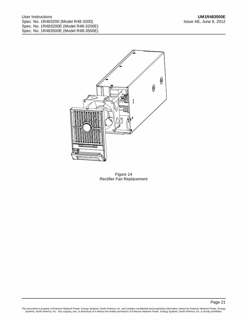
Rectifier Fan Replacement
Each Rectifier uses a fan (P/N 32010086 for 1R483200 rectifier module. P/N 32010109 for 1R483200E and 1R483500E rectifier module) for cooling. If fan replacement should become necessary, perform the following procedure.
Refer to Figure 14 as this procedure is performed.
Caution: In a system with NO redundant Rectifier, battery must have sufficient reserve to power the load(s) while the Rectifier is removed for fan replacement.
Note: When performing any step in this procedure that requires removal of existing hardware, retain all hardware for use in subsequent steps.
Procedure
1) Performing this procedure may activate external alarms. Do one of the following. If possible, disable these alarms. If these alarms cannot be easily disabled, notify the appropriate personnel to disregard any alarms associated with this system while this procedure is performed.
2) Remove the Rectifier from the shelf. Refer to a previous procedure for step-by-step instructions.
3) On this Rectifier, loosen the three (3) screws on the baffle (Rectifier front cover) and remove the baffle.
4) Unplug the power cable of the fan and remove the fan.
5) Place the new fan in the space vacated by the old fan.
6) Plug the fan power cable back into the corresponding socket. Push back the fan (the side with the tag facing inward). Position the front baffle back into place and fix it with the screws removed in step 3).
7) Replace the Rectifier into the shelf. Refer to the previous procedure for step-by-step instructions.
8) Enable the external alarms, or notify appropriate personnel that this procedure is finished.
9) Ensure that there are no local or remote alarms active on the system.
User Instructions UM1R483500E Spec. No. 1R483200 (Model R48-3200) Issue AE, June 8, 2012 Spec. No. 1R483200E (Model R48-3200E) Spec. No. 1R483500E (Model R48-3500E)
Page 21
This document is property of Emerson Network Power, Energy Systems, North America, Inc. and contains confidential and proprietary information owned by Emerson Network Power, Energy Systems, North America, Inc. Any copying, use, or disclosure of it without the written permission of Emerson Network Power, Energy Systems, North America, Inc. is strictly prohibited.
Figure 14 Rectifier Fan Replacement
UM1R483500E User Instructions Issue AE, June 8, 2012 Spec. No. 1R483200 (Model R48-3200)
Spec. No. 1R483200E (Model R48-3200E) Spec. No. 1R483500E (Model R48-3500E)
Page 22
This document is property of Emerson Network Power, Energy Systems, North America, Inc. and contains confidential and proprietary information owned by Emerson Network Power, Energy Systems, North America, Inc. Any copying, use, or disclosure of it without the written permission of Emerson Network Power, Energy Systems, North America, Inc. is strictly prohibited.
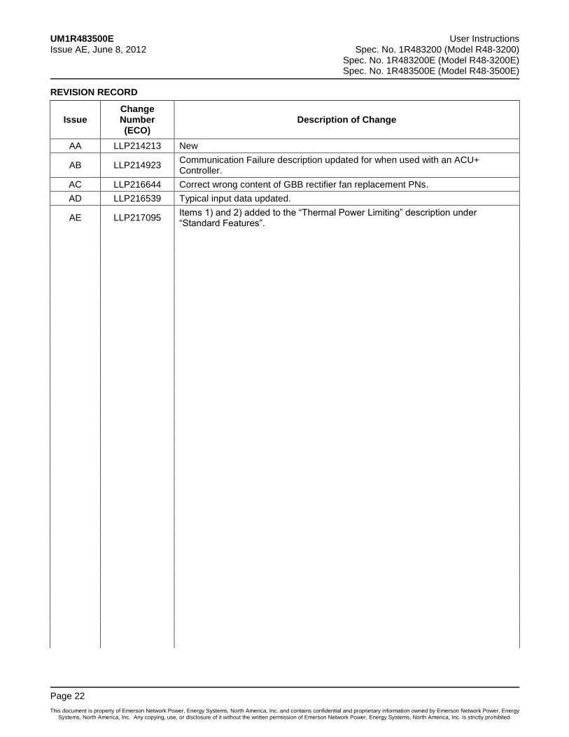
REVISION RECORD
Issue Change Number (ECO)
Description of Change
AA LLP214213 New
AB LLP214923 Communication Failure description updated for when used with an ACU+ Controller.
AC LLP216644 Correct wrong content of GBB rectifier fan replacement PNs.
AD LLP216539 Typical input data updated.
AE LLP217095 Items 1) and 2) added to the “Thermal Power Limiting” description under “Standard Features”.

NetPerform™ Optimization Services
At Emerson Network Power, we understand the importance of reliable equipment – it’s critical to both
your business and your bottom line. That is why we offer a wide array of services to meet all of your
network infrastructure needs.
Technical Support
Email [email protected]
Answers technical product and system
questions; determines status of warranties and
contractual agreements for repair. Phone 1.800.800.5260
Services - Design, Deployment & Optimization
Email [email protected] Provides quotes and bid responses, order
placement and scheduling for design, and
deployment and optimization services.
Download service & maintenance reports
online.
Phone 1.800.800.1280, option 7
FreedomCare Secure.EmersonNetworkPower.com
Spare Parts
Email [email protected]
Pricing and PO processing of spare parts,
including but not limited to breakers, cables,
fuses, rectifier fans, misc. breaker and fuse
panels, enclosure fans, doors & switches, etc. Phone 1.800.800.1280, option 5
DC Power Depot Repair
Email [email protected] Creates and processes RMAs, determines
lead times and pricing, provides repair
shipping information and status. Phone 1.800.800.1280, option 6
DC Power Product Training
Email [email protected] Requests for quotes, order placement and
scheduling. Phone 1.800.800.1280, option 8
For More Information To learn more about service offerings from Emerson Network Power, please contact your sales
representative, call 1-800-800-1280 option 7, email [email protected] or visit
www.EmersonNetworkPower.com/EnergySystems.

Recommended