ELEMENTYour Guid to Foundries in Pakistan
www.pfa.org.pk3rd Quarter 2015
Industrializing Pakistan


1
Pakistan Foundry Association is moving forward towards enhancing the
Technological levels of our foundry. I congratulate Dr. Fazal-e-Khalid,
Vice Chancellor of UET for being elected as the Chairman of Managing
Committee of Foundry Service Center and acknowledge the tireless effort
of Mr. Alamgir Chaudhry and SMEDA team. I look forward to a very
productive and efficient use of this facility and urge all our members to
visit and establish close liaison with Foundry Service Center.
I am delighted to announce the beginning of transition of conventional
foundries to modern foundries in Pakistan, with the training workshop on
“Iron Casting Methoding” by Mr. Nabeel Khan, a UK based global foundry technologist having 23 years of
international experience in the metal casting industry across the three continents and extensively
involved in the foundries. This way forward will play a vital role in enabling foundry men to do castings
based on calculated parameters and use modern software for value addition in castings. Based on success
of our first workshop, 4-5 more such workshops will be organized in near future.
I appreciate the sincere services of Mr. Nabeel Khan to stand alongside with Pakistan Foundry Association
and thank Mr. Asim Qadri for identifying him as a resource and support to Pakistani foundries.
Significance of year 2015 has further increased with installation and use of Magma soft in private sector
marking the beginning of modern foundry era and instilling a culture of consciousness and waste reduction
in the foundry sector.
-0300 8673873
Joint SecretaryPakistan Foundry Association
2
6
14
18
24
30
32
34
Pakistan Foundry Industry Current State and Strategy for Moving Forward
Aluminium low-pressure wheel production end to end solutions
Getting Hi-Tech
Common Questions, Expert Answers
Co2 cured phenolic, a new gas curing mold/core making system
Development of Compacted Graphite Cast Iron (CGI) in Ravi Autos
Pakistan Metal Casting and Manu-facturing Scene.
Re-establishing and Rehabilitating F o u n d r y a t K a r a c h i S h i p y a r d & Engineering Works Ltd.

2
foundry industry and spoke about the key
challenges our industry is confronted with.
Theinteractive session generated interest and
involvement among the audience who also added
towards defining the main issues and their
causes. He went on providing with a brief insight
into the trends in the modern foundry industry,
process control capabilities focusing on the role of
methoding engineer and the need to enhance
methoding engineering skills across the board.
He then concluded by suggesting the way
forward. Below is a brief review of his talk.
Pakistan Foundry Industry –Current State:
The main drivers of the Pakistani Foundry
Industry are Auto, Agri-implements including
tractors, Sugar, Cement, Mining and Defence
Castings. These are generally influenced by
quality, price, casting design and types.Millat
Tractor greatly influencesthe dynamics of ferrous
casting industry as most foundries are vendors
for Millat parts and quality, price, casting design
are driven by Millat. The industry is developing
at a very slow paceand is generally lacking
maturity in the areas of systems, processes and
process control. Huge inputis required to bring
these at par with global qualitysystems and
processes.
Key Issues and Challenges:
The foundry industry in Pakistan seems to be
suffering from status quo syndrome with little
willingness to undergo the change in mind set for
adopting new technology, Mr Nabeel Khan
emphasised. The skil l level of foundry
engineers/technicians is generally not up to the
mark. There is reluctance on the part of
engineers to start career in the Foundry industry.
The employers are also not keen to employand
retainqualified engineers or technicians
primarily due toi)lack of essential knowledge
about foundry practicesand processes, ii)
reluctance to spend time on the shop-floor and iii)
lack of initiative and innovative ideas.
Most foundries are cost driven. There is little
awareness about the quality parameters of the
cast products, therefore the cost driven culture
prevails.
The Pakistan Foundry Association organised a
presentation and interactive session on
17August on Skills, Capabilities, and Process
Control in Global Foundries - Way Forward for
Pakistani Foundry Industry, by Mr. Nabeel
Khan, a UK based global Foundry Technologist
with more than 23 years of experience in the
metal casting industry. Mr. Khan has been
extensively involved with global automotive
foundries most significantly in Australia, New
Zealand, Malaysia, Thailand, Indonesia, Iran,
towards the development of foundry systems and
process control measures for the production of
"zero defect castings".
Mr. Khan presented an overview of the Pakistani
Pakistan Foundry Industry
Current State And Strategy For Moving Forward
The clear issues which the
Pakistan foundry industry
m u s t t a c k l e a r e s k i l l s
development and adaptation
o f m o d e r n t e c h n o l o g y ,
delegates were informed

3
Foundries need some degree of automation–from
melting,moulding, pouring, fettlingto heat
t r e a t m e n t . O n l y a f e w u n i t s h a v e
automatic/semi-automatic moulding lines.
Melting/Pouring and Melt Treatment technology
(like auto pour/press pouringfurnaces/vacuum
treatment), methoding generally do not exist.
With the exception of few foundries the sand
quality level is questionable which limits the use
of organic binders systems and hence sand
reclamation levels are poor. Defect analysis
capability (simulation software / microscopy /
spectro-analysis labs / mechanical testing) is
seldom used and is only seen in limited foundries.
Trends in the Modern Foundry Industry:
The Role of Methoding Engineer in a Foundry
Elaborating on the role of methoding engineer in
the foundry, Mr. Khan commented: "The
methoding engineer is the link between the
pattern equipment, the moulding process, the
condition of the liquid metal, the mould filling,
the solidification process, the ways the foundry
clean (or "fettle") and even the heat treatment"of
a casting.
How do Modern Foundries Utilise SimulationSoftware
Areas Issues/Challanges

4
Driving the Industry Forward:
Mr. Khan strongly emphasised on the need forthe
PFA, Foundry Service Centre and Academia to
work together closely to develop a sustainable
foundry industry in the country.
Suggested initiatives:
Ÿ P r o m o t i o n o f c l u s t e r d e v e l o p m e n t
programmes.Creation of common facilities for
modern design, manufacturing tools,
simulation, defect analysis and testing.
Ÿ Conservation of natural resources, waste
reduction, sand recycling in clusters.
Ÿ PFA to act as a bridge between academia and
the foundry industry. Introduce Foundry
courses with collaboration of Academic
Institutes. Organise internships in foundry
sectors to encourage students to enter in the
foundry industry.
Ÿ Production of a foundry-man skills set list.
Ÿ Develop programs to uplift the skill levels of
the cluster foundry engineers.
Ÿ Methoding engineering skills to be enhanced
across the board.
Ÿ Signing of memorandum of understanding
with global Foundry Institutes (China, India)
for the exchange of information and
knowledge sharing.
Acknowledgements
Mr. Nabeel Khan concluded his talk by acknowledging and thanking Prof. Dr. M Iqbal Qureshi for providing an overview of the current state of our Foundry Industry and the challenges the industry is facing.
Mr. Khan also thanked Mr. Asim Qadri, Director Operations - Qadri Group of Foundries and Mr. Abdul Rasheed, secretary PFA for giving an insight into the state and issues of our Foundry Industry and appreciated their assistance in organising and facilitating this talk.


6
Roger Kendrick, Foseco Europe; Giorgio Muneratti, Vesuvius Italy; Martin Freyn, Vesuvius Slavia;
Philippe Kientzler, Foseco International; Gustavo Martinez, Foseco Mexico and Eiyu Tei, Foseco Japan
There has been huge growth in the production of aluminium road wheels over the past decade, with the
great majority being manufactured by the low-pressure diecasting process. The quality requirements of
these safety critical castings are as high as any aluminium component made today and Foseco has
developed a range of products aimed at improving the quality of the castings produced while also improving
the profitability of the process.
This concept of an integrated solution package for a particular casting and process will be further
developed in the future.
Fig.1 Tower melting furnace showing differentrefractories for different requirements
Aluminium Low-pressure Wheel Production
End To End Solutions Roger Kendrick Foseco,
Permitted by lynn Postle
Foundry Trade journal International.
7
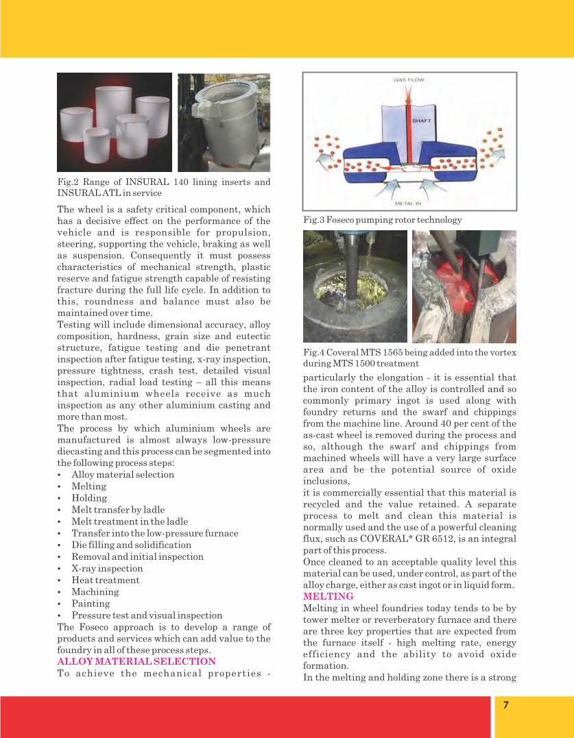
Fig.2 Range of INSURAL 140 lining inserts and INSURAL ATL in service
Fig.3 Foseco pumping rotor technology
Fig.4 Coveral MTS 1565 being added into the vortex during MTS 1500 treatment

8
AlSi7Mg as-melted before
treatment
AlSi7Mg after 10 minutes
FDU treatment
AlSi7Mg after 10 minutes
MTS 1500 treatment
Inclus
ion Inde
x
Featur
es
0.5 - 2
.5 m
icro
n
2.5 - 5
.0 m
icro
n
5.0 - 1
5 micro
n
15 - 30
micro
n
30 - 75
micro
n
> 75
micro
n
Num
ber
Fig.5 Graph showing relative effectiveness of cleaning from FDU and MTS 1500 treatment. Features are oxides and pores within the sample Fig.6 Dry dross after MTS 1500 treatment
Fig.7 Excessive dross from standard treatment
Fig.8 Reduced dross from COVERAL MTS 1565 treatment
Fig.9 Before treatment

9
Fig.10 After COVERAL MTS 1582 treatment
Fig.11 Low-pressure furnace showing different refractories used, LPS riser tube and heater protection tubes
Fig.12 Ceramic assembly
Fig.13 Typical INSURAL 50 inserts

10

11
Contact: Paul Jeffs, UK technical manager, Vesuvius UK Limited – Foseco Foundry Division, Tamworth, Staffordshire B78 3TL UK.Tel: +44 (0) 1827 289999,email: [email protected]: www.foseco.com
*COVERAL, ALUGARD, TRIAD, BLU-RAM, D U R A G U N , I N S U R A L , N U C L E A N T , THERMATEST, LITEWATE, ZYAROCK, ZYACAST, SEDEX, STELEX, SIVEX and DYCOTE are Trade Marks of the Vesuvius Group, registered in certain countries, used under licence.


14
rupees annually.
Since 1980s, manufacturing has been totally revolutionized. The use of Computers in making of Drawings (Computer Aided Drawing or CAD), running the machines (Computer Aided Manufacturing or CAM), and Analyzing the Engineering Process and Designs (Computer Aided Design/Computer Aided Engineering or CAE) by Simulation is considered a norm in any modern industry. During past 30-years, the use of computers has not only increased the efficiency of the machines, but it has also allowed the engineers and researchers to go into the depth of the manufacturing processes and apply their minds to fine tune the procedures. Resulting in a better product!
Let us see what is a Modern Flow for Design and Manufacturing of any component:
Step-1: Design of Part
Ÿ Concepts Designing on Paper with hand.
Ÿ Conversion of hand sketch to a 3D-Model Drawing on Computer using any 3D Modeling Software like Solidworks etc.
Ÿ Design Analys is /S imulat ions o f the Components (or complete machinery) on Computers by using any suitable/relevant software. For example for Foundry/Casting Procedures one may use ProCAST or MagmaSoft etc and for Stress Analysis or Motion Studies one can use Solidworks etc.
Ÿ Design Analysis is an iterative process, and in case of not achieving desired results, the Part/Machine's design can be altered on Computers.
Ÿ Upon achieving desired results on computer Simulations for the whole machinery, one may proceed with the individual component's manufacturing process optimization by the above mentioned software.
Ÿ One may spend some extra buck to get a pre-sample by using 3D Printing techniques. This step alone may save millions at the later stage. This helps in quickly making the component or machinery at this stage in Plastic or some Synthetic materials to ascertain the correctness of the component or fitting of the
Ever seen Grass cutting the Steel?
Not only that it is possible, the same is experienced by those who have used the Grass Chopper commonly known as "Toka". It is one of the high in-demand products of Pakistan and is manufactured from sand casting. The commonly used Toka in Pakistan and India is a state of the art engineering design. However, the primitive manufacturing technology combined with the non-adherence to the basic Quality manu-facturing procedures while Machining and Assembling Processes result in a massively "Mis-Aligned Machiner" which is "Forced" to be rotated under high inertia by using a heavilyover-rated electric motor. The resultant is a very quick wear of its gears and start of a chain reaction of changing the components and so on…
So is the case with almost every Agricultural Imp lement and Mach inery . From the metallurgical problems of as simple a part as a 'Till' (or "phallee") to the fancy-fabricated Harvesters and Wheat Threshers, all items are being produced in Pakistan without any Design Analysis and Due Engineering Calculations. One finds it quite interesting to see that the prime factor in selecting a Wheat Thresher by its buyers is its weight. It is a general perspective that the heavier the thresher, better it would be. It is totally ignored that the real parameter to see in selection of such machinery is its production efficiency and its components' life viz-a-viz its fuel consumption and maintenance required. There are no Standard Procedures to qualify and grade any implement on the basis of its efficiency and manufacturing quality.
This results in massive wastages as follows:
Ÿ Poor Production processes result in huge production loss to the manufacturers.
Ÿ Lack of Quality Procedures result in poorly manufactured machinery, resulting in very high running costs.
Ÿ Low quality components result in lesser machinery life, resulting huge replacement costs.
It would not be surprising to estimate the above mentioned losses running in many billions of
Getting Hi-TechMaj(r) M. Arfaeen Iqbal,
Electrical Engineer

15
components.
Do note that till this stage, everything is in the Digital format on Computers. But the thoroughly simulated and corrected design that we would have in the end of this stage will leave a little margin for Design errors once it is physically manufactured.
Stage-2:Manufacturing of Patterns / Dies / Molds and Machining
Ÿ The resultant of simulations and corrections of Stage-1 will be a verified CAD models in 3D format. These can easily be fed to CNC machines for making of the Casting patterns or Molds etc according to the procedure.
Stage-3:Production of Components
Ÿ The selection of right tooling, right machinery and process for production is critical of the Development Cycle. Computer Aided Engineering once again can save the design engineer from the hassles of doing repeated mistakes by carrying out all simulations of Machining processes on computers before selecting the machines. Today, one can easily run a tool-path simulation for all machining processes.
Ÿ For production process optimization, depending upon the volume or production and the desired precision tolerances, one may select the appropriate CNC or Special Purpose Machinery (SPM).
Ÿ There may be a possibility that in some large volume production cases, certain machining steps could be carried out by making a smart Machining fixture for a manual hand operated machine instead of using a CNC. A smart Design engineer or an experienced person can easily decide it.
Ÿ The use of computers in the supply chain management for the production process is a great help. Very complex decision making steps can be automated, like re-order levels of raw materials, stock positions in the inventory, wastage calculations, inward-outward flow control in the stores etc. Many ERP software tools are available for such purposes.
Stage-4: Quality Assurance and Process Optimization
Ÿ Proper use of modern portable gauges and
portable CMM machines have eased out the life for quality inspectors. Now, with the help of 3D CAD drawings on computers, one can easily run a comparison of dimensions on a produced component with that of the original design in 3D model.
Ÿ Process optimization is a continuous process which must be going on forever. Effective use of Feedback Data, Strict eye on Production rejections and losses is very helpful in improving in the yield of production and saving that extra dime.
Ÿ Most importantly, if one look at the rejections and production losses of any metal working setup (especially production foundries), one will notice the exorbitant numbers of rejections due to wrong pattern design or wrong casting parameters. We have seen the casting rejections of high-production foundries to be anywhere from 10% to 40%. All these can easily be brought down by employing the Computer Aided Design Analysis Software.
Another Rapidly upcoming technology in the manufacturing is 3D Printing. In a very short span of 15-years, 3D-Printing has taken over the world. Explaining this technology require separate space, but it is envisaged that very soon, metal-components manufacturing/production will be done on 3D Printers instead of in foundries or castings!!! Do you hear the tolling bells?
It is pertinent to note that modern Computer Aided Tools are amply available in Pakistan, but due to non-patronizing by the manufacturers, the young technicians and engineers are forced to use Pirated Software. Due to same reason, the Manufacturers of the Software are turning away from promoting their products in Pakistan.
There are a few Public-Sector organizations working in Pakistan to help the manufacturers in CAD/CAM sector, but these are not enough and these are not 'effectively affordable'. Today's manufacturers must come up with the investment on the Computer Aided Techniques under the licensed regime and help themselves come at par with the modern world.
The Engineering Universities and Technical Colleges have already given enough introduction and knowledge to the young graduates to work under a Supervised Design Setups based on

CAD/CAM technologies. It is the duty of the Industrialists to provide grooming environment to these graduates and technicians and to give them right direction…and….take advantage out of the Technology! If properly driven, The advantages in terms of time-lead and effort saving will soon make you forget the cost incurred on the acquiring the technology.
Maj(r) M. Arfaeen Iqbal, is an Electrical Engineer and working as a Manufacturing Technologist since past many years. During 22 years of his professional career, he has done different post-g r a d u a t e c o u r s e s i n C o m p u t e r A i d e d Technologies from Pakistan and Abroad. Based in Lahore, he can be reached by email at [email protected]
IMAGES FOR CAD and CAE
Design of Inspection fixture for Center Housing Casting
Simulation of Heat Flow from the Heat-Exchanger
Stress Analysis of a Connecting Rod in Design Phase
Loading and Bending Stress Analysis of a Bracket
Complex Component made by 3D Printing
Evaluating the Results of Casting Process Simulation
16

18
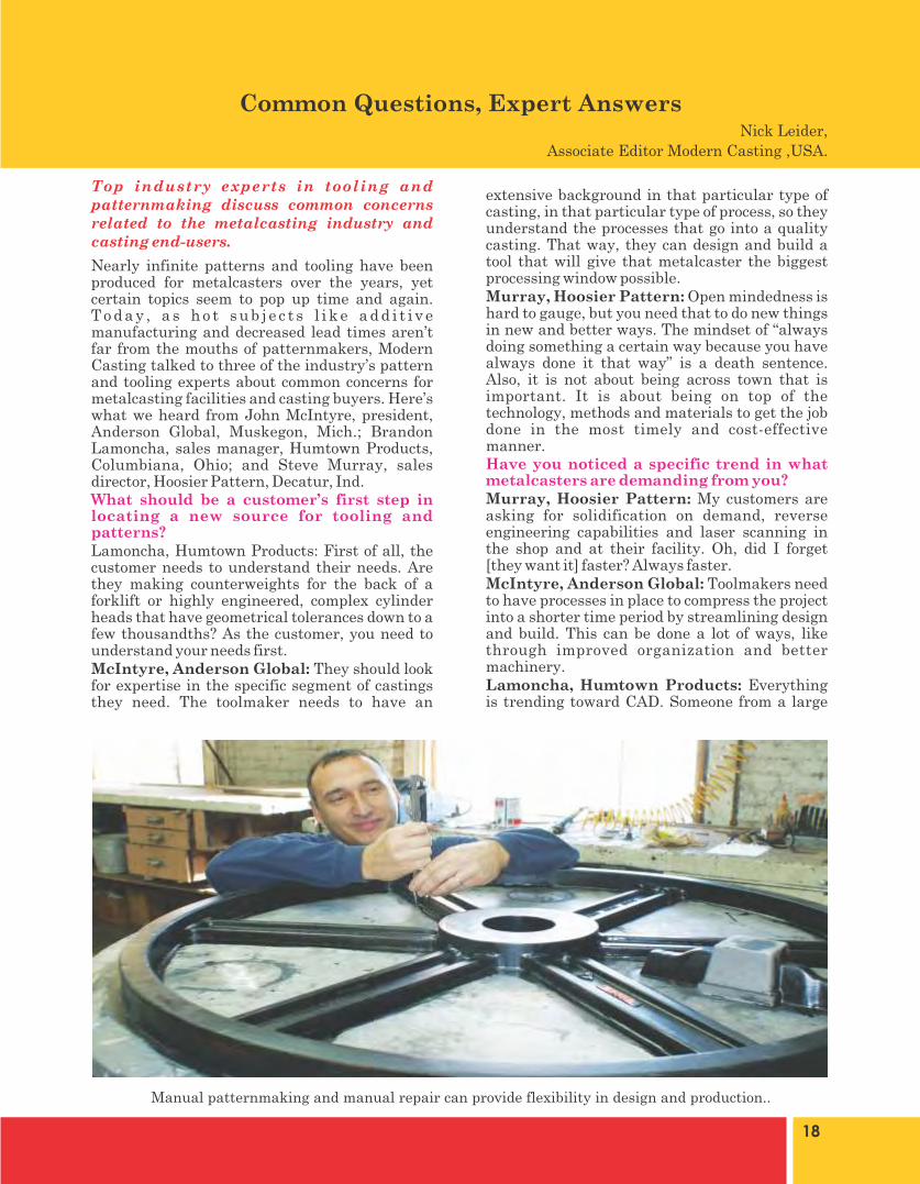
extensive background in that particular type of casting, in that particular type of process, so they understand the processes that go into a quality casting. That way, they can design and build a tool that will give that metalcaster the biggest processing window possible.Murray, Hoosier Pattern: Open mindedness is hard to gauge, but you need that to do new things in new and better ways. The mindset of “always doing something a certain way because you have always done it that way” is a death sentence. Also, it is not about being across town that is important. It is about being on top of the technology, methods and materials to get the job done in the most timely and cost-effective manner.Have you noticed a specific trend in what metalcasters are demanding from you?Murray, Hoosier Pattern: My customers are asking for solidification on demand, reverse engineering capabilities and laser scanning in the shop and at their facility. Oh, did I forget [they want it] faster? Always faster.McIntyre, Anderson Global: Toolmakers need to have processes in place to compress the project into a shorter time period by streamlining design and build. This can be done a lot of ways, like through improved organization and better machinery.Lamoncha, Humtown Products: Everything is trending toward CAD. Someone from a large
Nearly infinite patterns and tooling have been produced for metalcasters over the years, yet certain topics seem to pop up time and again. T o d a y , a s h o t s u b j e c t s l i k e a d d i t i v e manufacturing and decreased lead times aren’t far from the mouths of patternmakers, Modern Casting talked to three of the industry’s pattern and tooling experts about common concerns for metalcasting facilities and casting buyers. Here’s what we heard from John McIntyre, president, Anderson Global, Muskegon, Mich.; Brandon Lamoncha, sales manager, Humtown Products, Columbiana, Ohio; and Steve Murray, sales director, Hoosier Pattern, Decatur, Ind.What should be a customer’s first step in locating a new source for tooling and patterns?Lamoncha, Humtown Products: First of all, the customer needs to understand their needs. Are they making counterweights for the back of a forklift or highly engineered, complex cylinder heads that have geometrical tolerances down to a few thousandths? As the customer, you need to understand your needs first.McIntyre, Anderson Global: They should look for expertise in the specific segment of castings they need. The toolmaker needs to have an
Common Questions, Expert Answers
Manual patternmaking and manual repair can provide flexibility in design and production..
Top industry experts in tooling and patternmaking discuss common concerns related to the metalcasting industry and casting end-users.
Nick Leider,
Associate Editor Modern Casting ,USA.

19
OEM asked me: Is it the drawing or the CAD model that we’re working toward? For the most part, I don’t even get drawings anymore. When my grandfather made patterns off a drawing, he had to have that interaction with the foundry. Now, it’s a little bit different. If they see an area that has to be chilled or might shrink, they’re going to deal with that immediately.How can a casting buyer determine a good pattern from a bad one? What are key things to look for to ensure quality?McIntyre, Anderson Global: Depending on the personality of the casting buyer, he can insist on dimensional certification and proof that proper materials and heat treatment were used.Lamoncha, Humtown Products: We’ve gotten away from simple measurements and verniers. We just do a scan of our pattern with a laser. We do a comparison and send that along with the pattern. The proof ’s in the pudding. Everybody knows the pattern is not going to be absolutely perfect. But if you show you’re within the tolerances, they know if there’s any variation in a casting, it most likely is an in-house problem.What missed opportunities/misconceptions do you see from customers?McIntyre, Anderson Global: Not asking to participate. Many times, metalcasters will want a tool—and they won’t explain whether the castings will be low volume or high volume or they won’t detail its key characteristics. If that information isn’t communicated, the customer will get a generic tool that wasn’t specifically made to help them reach the goals of the casting.Murray, Hoosier Pattern: Mixing and matching materials and manufacturing methods to get the best fit for the specific need is OK. Pattern shops are here to help with questions on
new technologies, methods and materials. Ask why we still do things such-andsuch way. Explore your options.Lamoncha, Humtown Products: When people think of a patternmaker, they imagine someone gluing wood segments together or using a lathe. These are great tools that obviously still have their place, but we have so much more to offer. Our advanced methods are just additional tools in the toolbox. We are much more dynamic than that. We want to utilize all the technologies available. We want to have a CNC tooling shop and an advanced manufacturing shop in addition to our traditionalpattern shop.What should be the major considerations when choosing between offshore and domestic pattern suppliers?Murray, Hoosier Pattern: The same things you use to choose between domestic suppliers. We compete in a world marketplace today. You must be on your game to be competitive and have the services your customers require.McIntyre, Anderson Global: Materials. For overseas pattern shops, labor is inexpensive, so they focus on saving in terms of materials, which can lead to cutting corners. Also, being in the same time zone where you are speaking the same language can reduce compl icat ions in communication.Lamoncha, Humtown Products: The biggest consideration is time. I don’t think anyone can deal with the time lag [with overseas suppliers]. If there’s a revision or a change, it takes way too l ong to go back and f or th . How have advancements in additive manufacturing affected your business?Murray, Hoosier Pattern: It is not just another
Traditional pattern materials, such as metal and wood, remain relatively unchanged.

20
tool in the toolbox. It is another drawer in your toolbox. We want to show customers where and when to apply the technology and guide the customer through that maze of technological hype versus reality. Yes, we can print a pattern or corebox for low volume production, but you have to do a cost-benefit reality check. It has to make sense dollar and cents-wise.Lamoncha, Humtown Products: We want our customers to understand that advanced manufacturing isn’t only additive, but it’s a fundamental tool. It’s the ruler, the tape measure—something you’ll be using very frequently. But some people get enamored with one technology and won’t look elsewhere. By keeping an open mind, you will be able to get better castings at a much lower cost. What’s one surprising way for metalcasters to utilize pattern shops to streamline the supply chain?McIntyre, Anderson Global: Have the toolmaker visit your foundry, your coreroom, your molding line. Have them talk to in-house maintenance people to find out what problems they’ve had in the past, what problems they’ve had in the foundry, so the tooling shop can use that knowledge to produce a better tool.Murray, Hoosier Pattern: Establish standard prices so you know what you are getting into before you do something. Things like re-rigging, remounting and core box maintenance should all be fairly predictable. Try to eliminate surprises in that regard.Lamoncha, Humtown Products: In terms of the supply chain, you really have to look at a pattern shop like a partner and not just a supplier. In the end, the goal is to make the end customer happy. If a tool shows up and it’s not working as expected, it’s easy to start pointing fingers and that’s counterproductive.
What’s a common misconception you encounter regarding tooling ownership and/or storage?Murray, Hoosier Pattern: Tools will last forever and storage is free. The truth is much different. Old wood patterns and coreboxes dry out and degrade. Iron will rust and corrode. Regarding storage, there is a cost to bring tooling out of storage after many years and getting it ready for production.What’s one unexpected benefit for a metal casting facility to out source its production of patterns and tooling?Murray, Hoosier Pattern: Speed. If you can outsource a part when it makes sense, you can use the technologies offered by the pattern shop without owning the machinery.Lamoncha, Humtown Products: You gain a lot of knowledge working with a pattern shop that builds tooling for all different industries. I’ve built 30-40 tools in the last few months in all different industries, so I have a different way of looking at a particular corebox or casting.
This rapid prototype, produced in just 17 days, is an example of patternmakers and metalcastersworking together to streamline the supply chain.
Metalcasters should work with pattern shops to choose the best material and process for theintended casting.


24
process is still being used ,particularly in areas
like thin sectioned and rangy cores like water
jacket , oil passage and molds for two wheeler
cylinder assembly ,molds and cores for cam shaft
etc for variety of reasons like ease of ejection , un
match able handl ing strength, unique
collapsibility , near perfect dimensional accuracy
of castings etc.
In automotive sector , it's common practice to
make molds by green sand and cores by Shell or
PUCB mainly because of viable economy. With
passage of time, more and more complicated cores
are being converted from Shell to PUCB for
obvious benefits using special sands like mix of
silica and Chromite, Mullite etc.
Whereas CO2 cured Phenolic can't enter into
area of Shell for automotive castings, it can
partially substitute PUCB in many cases. One of
the main reasons for this switch over is
continuous increase in cost of PUCB making the
new system, once costlier, becoming increasingly
viable. The other being impact on environment,
where it outplays PUCB.
It 's another area of application can be
substitution of sodium Silicate, curing agent
(CO2) remaining same. Sodium silicate or water
glass system is probably first synthetic sand
binder system introduced in foundries for making
molds and cores. In spite of it' s several
advantages over ancient binders like cereal
binders, baking oils, green sand process etc, being
inorganic in nature , de coring and poor surface
finish of castings, requiring re work remains a
problem. Thus, with introduction of organic sand
binders from time to time , silicate has been
continuously replaced by modern organic binders
.CO2 cured Phenolic is seen as replacement of
Sodium silicate system ,which ,being organic in
nature ,gives excellent collapsibility of core/mold
assembly, post pouring of castings.
System in brief:
Like Sodium silicate, binder component is single
part; a typical resole type Phenol Formaldehyde
resin.CO2, in gaseous form is the curing agent.
Thus, basically it is two component systems.
Abstract:
Organic binders , baking and no bake ,self-sets
and gas curing types, have been introduced
periodically by replacing inorganic binders like
water glass (sodium silicate) & phosphates and
cereals like starch, vegetable oils , molasses etc.
to meet requirements of modern Foundries like
high productivity, least possible cleaning
operations, close dimensional accuracy and
surface finish of castings with near perfection.
Many of these binders have been phased out by
newer ones providing overall advantages and
demand for many are growing continuously.
Some are not having much popularity but are
being used in limited number of Foundries.
Co2 cured Phenolic, introduced in Foundries
towards end of 20th century has started gaining
popularity at beginning of 21st century in
Foundries in India and sub continent.
Low energy consumption for making molds/cores
by this process combined with fast productivity
,clean working place environment, ease of knock
out and excellent casting finish for ferrous and
non ferrous metals are some of the features
attracting Foundrymen to prefer this system over
others.
This paper will deal with possible future of this
comparatively new gas curing organic binder
system with emphasis on its possible areas of
application, alone or in combination with water
glass system.
Introduction:
While discussing about possible areas of
application of this modern gas cured binder
system, we need to review about existing systems
which can be substituted.
In automotive sector ,repetitive thick sectioned
cores like blocks and heads ,once being produced
by Hot box and Shell process, both heat curing,
have largely been substituted by amine cured
Cold box process (PUCB) over a period of time,
mainly to save energy and faster productivity.
However, whereas Hot box is almost nonexistent
in Indian Foundries pouring ferrous metal, Shell
Co2 Cured Phenolic, A New Gas Curing Mold/Core Making
System D .Ghosh, Director(technical)
For Ace Polymers India [email protected]

25
Resin properties:
Appearance : Yellow colored liquid
Viscosity : 40-60 secs
(Ford cup no 4, 30 DC)
Water miscibility : Unlimited
Sp.gr : 1.28-1.32
PH : 14
Free Phenol : <_ 1%
Free formaldehyde : <_ 0.1%
Advantages offered
Ÿ Resin is water soluble
Ÿ Compatible with silica, zircon and Chromite
sand
Ÿ Short curing cycle
Ÿ Good flow ability of mixed sand
Ÿ Unique storage stability of mixed sand -
more than 4 hours
Ÿ Long shelf life of binder
Ÿ Molds/cores are resistant to atmospheric
degradation
Ÿ Suitable for batch as well as continuous
mixers
Ÿ Over gassing does not reduce strength of
molds/cores
Ÿ Binder is non flammable
Ÿ N, S and P free system
Ÿ Suitable for Ferrous as well as non Ferrous
metals
Ÿ Castings are usually free from veining and
lustrous carbon defects
Ÿ Excellent post casting breakdown properties
Ÿ Excellent work place environment
Ÿ Viable economy
Binder/CO2 demand
Usual binder demand is 2.5-3.0 % by weight of
sand.CO2 demand is 0.5-2% by weight of sand.
Process and possible areas of application
Sand can be mixed in all types of mixers .Mixed
sand can be used like sodium silicate mixed sand
by passing CO2 through molds/cores through
holes made.
Mixed sand can be stored safely up to 4 hours
without deterioration of properties. If kept
covered with wet jute bags, it has been found to
remain usable up to 24 hrs.
Typical CO2 flow rate and pressure requirements
are 5-20 lts/minute and 0.5-1 kg/sq cm
respectively.
It can find four distinct areas of application,
which is as follows:
a) Substitution of PUCB
Originally found to be costlier than PUCB
because of higher binder demand, sharp increase
in raw material prices for PUCB has made the
new system competitive.
Practical example of producing cores for
automotive castings in automatic core shooters
with this new system in green sand molds
,although not common so far ,exists in India
.Casting results are absolutely satisfactory
,surface finish being better than that obtained
using PUCB. Working environment is much
cleaner.
b) Substitution of Water glass process
Whereas process of application of both the
processes are same, resin binder enjoys series of
benefits over silicate. These are:
Increased Bench life of mixed sand
Better flow ability of mixed sand
Non reversal in strength on over gassing
Increased storage life of cores
Better casting finish
Better collapsibility- and many more
c) Substitution of so called beta set core
In foundries practicing so called alpha set mold/
beta set core system ,core making can be replaced
by this system producing cores of better quality
without affecting reclaim ability by attrition,
working environment being far better.
d) Hybrid system optimizing economy and
casting quality
Molds with resin sand at facing and silicate at
backing can be co cured by CO2.These molds
when used with resin/CO2 cores ,produces
casting offered by sophisticated organic binders
with working environment matching silicate
system.

26
Two halves of molds made with 3% CO2 cured
Phenolic facing and 5.5% CO2 silicate sand
Core made with 3% CO2 cured Phenolic sand
Bottom mold core assembly
Valve body casting (steel , WCB) using above
mold/core assembly
Coating practice:
It has been found that castings of reasonably good
quality can be obtained without application of
refractory coatings using molds and cores made
with this system. However , both water and
thinner based coatings are compatible for the
system.
Strength:
Typical dry compression (Kg/sq cm) of the system
@3.0% binder level in crushed quartz of AFS 46.
Immediate after gassing : 8-9
1 hr .after gassing : 12-14
4 hrs : 14-16
24 hrs : 17-18
Compatibility with green sand:
There are practical examples in India where
castings are being produced with green sand
molds and CO2 cured Phenolic cores .Core sand
on mixing with green sand does not poison
bentonite.
Casting Quality:
Ferrous castings produced with this system have
been found to be free from veining, lustrous
carbon, hot tear and pinhole defects .Copper and
aluminium alloys are successfully poured with
this system.

27
Environment:
Mixing area is free from obnoxious fumes usually
experienced with other organic binders.BTX
emission in pouring area is much lesser
compared to cases using most of the organic
binders.
Drawbacks:
The system is not compatible with Olivine sand
which is usually used in facing area of molds
producing Mn steel castings.
When compared with PUCB, this system offers
poor flow ability of mixed sand leading to
comparatively porous cores.
Thin and rangy cores and molds like water
jacket, oil passage, inlet exhaust port core, brake
disc etc cannot be made of this system.
Conclusion:
One more gas curing system has been made
available to Foundries in Indian subcontinent
with existing PUCB .This system has got lots of
positive features a good binder system should
have. These include fast productivity of
molds/cores as well as castings, excellent work
place environment, suitable for pouring ferrous
and non ferrous castings and favorable economy.
Few drawbacks are non compatibility with
Olivine sand, poor flow ability of mixed sand and
comparatively inferior handling strength
compared to many organic binders.
Thus, with its strength and weakness, this
binder system, considered to have combined
benefits of organic and in organic binders, is
going to cement it's place in many of foundries in
India and sub continent in years to come.


30
Comparison:
Comparison of mechanical & physical properties between Grey, Compacted graphite & ductile irons.
Benefits:
CG Iron V/S Grey Iron
Ÿ The Strengths and Impact toughness of CG Iron are much higher than that of Grey Irons.
Ÿ Tensile strength of CG Iron is greater than Grey Iron.
Ÿ It has Damping properties like grey Iron
Ÿ The heat resistance fatigue performance is much higher for CG Iron than Grey Iron.
Ÿ Wear resistance of CG iron is more than grey Iron
CG Iron V/S Ductile Iron
Ÿ Hardness of CG iron is nearly equal to Ductile Iron.
Ÿ Its elongation is lower than Ductile Iron.
Ÿ CG iron has ductility as Ductile Iron.
Ÿ No Warpage due to heating/cooling over the time due to its matrix
Main Applications:
Ÿ The first commercial application for compacted graphite iron was for the Brake Discs for high speed rail Trains
Ÿ More recently compacted graphite iron has been used for Diesel Engine Blocks
Ÿ It is also used for Turbo Housings and Exhaust Manifolds.
Ÿ Fly Wheels of high efficiency cars.
Introduction:
The shape of free carbon in the metal matrix determines the category of cast iron such as Grey iron, SG Iron or CG Iron. Shape of graphite in Compacted Graphite Irons is like a worm or stubby form with rounded edges. It is also known as vermicular graphite cast iron. The production method is similar as that of ductile iron. Some rare earth element and an alloying element such as titanium are required to minimize the formation of Spheroidal Graphite.
Mechanical properties of SG Iron depend on Nodularity and ferrite-pearlite content in the matrix. While the flake shape and flake size decides the mechanical properties in Grey Iron. In CG Iron, the vermicular or compacted shape of graphite makes it fall in-between GI or SG Iron.
The term "vermicular" is derived from the worm like shape of free graphite in matrix and is used to illustrate compacted graphite iron. Generally the term "compacted" is used to describe this kind of structure as it easy to understand.
Why Developed:
With the growing needs of Automobile amenities, it is required to upgrade automotive industry with the new and improved materials that can work more efficiently in severe conditions. CG Iron is the upcoming addition in automotive parts manufacturing industry as it has mechanical properties intermediate between gray iron and ductile iron.
Keeping in mind the international trends in material development and usage, it was observed that in Auto Industry the future of CGI is very bright, which is also evident from the table below.
Trends in United States Diesel Penetration Predictions for future.
Table:
Development of Compacted Graphite Cast Iron (CGI) in
Ravi AutosPrepared By: Ijaz Ali Behar (M.Sc Metallurgy & Materials Science)
M. Mubbashir Saeed (B.Sc Metallurgy & Materials Science) Qaisar Nawaz (B.Sc Metallurgy & Materials Science)
Special Thanks: Mr. Pervaiz Mahmood (G.M. Foundry Ravi Autos)Presented By: Ijaz Ali Behar (Manager Foundry Ravi Autos)

31
Development at Ravi:
CG Iron can be produced by the following two methods.
First method is called under-treatment by magnesium (keeping in mind the ductile iron Mg treatment process) and second method is known as Mg + Ti treatment. Following is the brief description of these two techniques and discussion on the results of these techniques which were observed during production of CGI in Ravi Autos.
1. Under treatment method
Typically residual magnesium ranges from 0.035% to 0.065% in ductile iron, depending on the type of castings and section thickness of casting being made. In case of compacted graphite irons, the residual Magnesium ranges from 0.015 % to 0.022%. This composition can be achieved using standard FeMgSi alloys. But practically this method is very difficult and requires strong control on the Mg treatment process. If Mg content is too high, it will result in high nodule count. Too low Mg will lead to the formation of flake structures, particularly in thicker sections. In castings of multiple section thicknesses, this method is practically impossible to control and is not widely used.
At Ravi Autos we tried with different Mg content in the melt to obtain compacted graphite structure, but it was partially successful, the main reason being inconsistency in CG structure.
The metal was tapped at temp varying from 1470 °C to 1500 °C. Metal behavior with respect to shrinkage was like Ductile Iron, as such the Gating System was designed accordingly. As in SG iron the metal was consumed in 5 minutes. In the initial days of this experiment we completed the pouring in min possible time so that Mg can retain in the metal composition and flake formation could be avoided. But it resulted in complete nodule formation. To avoid this we delayed pouring practice so that only required content of Mg could retain. But we could not get the desired consistency.
2. Magnesium plus titanium treatments
In this method the melt is prepared and magnesium treatment is performed similarly to that of Ductile Iron. The difference is low Mg content in the melt and addition of Titanium to the process. This Ti may be in the form of Fe-Ti or
combined with Fe-Mg-Si. Typical range of residual Ti is 0.07% to 0.10 %. Titanium is a flake promoter element and this method gives a wider production range than the Mg under-treatment method. That is why CG structures can be obtained in both thin and thicker sections.
The Titanium was added with a trace amount of Cerium Misch-metall. With this method the results attained were consistent having better control of CG Iron structure.
Tapping temperature was kept at 1480 °C. Pouring time range set at 4 to 4.5 minutes. Behavior of molten metal was same as in ductile iron. It was noted that loss of temperature in compacted graphite iron is a little less than ductile iron during poring practice.
Comparison Table & Micrograph Pictures
Cost Comparison Chart:
References:
1. BCIRA Broadsheet 138: Principal Graphite forms in cast Irons.
2. BCIRA Broadsheet 180: Compacted Graphite Cast Irons.
3. C . M . E c o b a n d C . H a r t u n g , " A n Alternative Route for the Production of Compacted Graphite Irons" Elkem ASA, Norway.
4. International Standard-ISO 16112, First e d i t i o n 2 0 0 6 - 0 8 - 0 1 , " C o m p a c t e d ( v e r m i c u l a r ) g r a p h i t e c a s t i r o n s - Class i f i cat ion" Reference number ISO 16112:2006(E)
5. Stieve Dawson, "Practical Applications of Practical of Compacted Graphite Iron" SinterCast, 2 June 2005

32
Pakistan Metal Casting and Manufacturing Scene.
Permitted by Metal Casting Technologies magazinehttp://metalsonline.rala.com.au
levels of mechanisation have been established.
Major foundries are owned by players in the auto
parts sector. "Companies like Bolan Castings,
KSB Pumps, Rastgar Engineering and MECAS
continue foundry-related modernisation plans,
but all supply into the local or global auto parts
value chains. In each case the foundry is captive
of its holding company or directly part of the
process of manufacturing end products."
Add to that Pakistan's booming middle class,
which is driving strong domestic growth, and the
country's economics are growing at a decent rate.
Even family-owned foundries are sitting
comfortably, with steady demand despite little to
no prospect of new work or investment.
Withstanding the positive sentiment, Pakistan
still has key gains to make in its environmental
and occupational health and safety practices
from an industry perspective. However, unlike
other surrounding Asia Pacific countries,
foundries are yet to be grossly impacted by rising
labour wages, which remain in moderation.
Automotive work drives outputs
The automotive sector is deeply ingrained in
Pakistan's foundries. The industry has enjoyed
favourable growth in the past three years,
according to Rashid, as consumers increasingly
take up personal transportation and foreign
investors take advantage of Pakistan's
favourable manufacturing conditions.
"Despite current economic situation, Pakistan is
set to become a market for 115,882 cars in the
year 2013-14 as compared to 106,968 in 2012-13,"
he said, adding, "and 691,037 motor cycles in the
year 2013-2014 as compare to 710,553 in the year
2012-13.
"That's in addition to bus, truck and farm
machinery sectors.
"Major multinationals in auto, engineering, food,
pharmaceutical and cosmetics have already
entrenched themselves here, with stellar results.
"To fulfil the future demands of casting in
Pakistan as well as for export destinations, the
Japanese and Chinese auto giants … or their
Preparing for the China moment
It would be fair to say Pakistan ranks as a dark
horse within the Asia Pacific foundry network.
While it may not place among the leading
producers of casting nations around the world,
with an approximate output of 350,000 annual
tonnes, the country is slowly building momentum
as a formidable manufacturer, learning lessons
from its surrounding neighbours.
As it stands, the Pakistan industry comprises
1640 foundries operating in grey, SG iron, steel
and non-ferrous castings, plus a marginal trade
in aluminium die castings.
Those parts span several different industries
including automotive parts, tractors, sugar mill
machinery parts, cement factory consumables,
chemical factory consumables, agriculture
implements, heavy industrial castings, pumps,
valves electric motors and textile machinery,
among other services.
The industry has already experienced
progressive growth over the past five years
thanks in part to strong exports to US, Germany,
UK, Brazil, Netherlands, Japan, Afghanistan,
France, Saudi Arabia, Italy, China and India,
among others.
In the 2013-2014 financial year, the industry
exported $263.1 million (US) worth of casting
products, more than double that of the 2009-2010
financial year ($116.7 million), but down slightly
against 2012-2013 and 2011-2012. Foundry
products now account for 21 per cent of Pakistan's
total engineering exports.
According to industry analyst and secretary,
Abdul Rashid, Pakistan's low labour costs and
manufacturing flexibility position the casting
industry favourably for overseas investors and
entrepreneurs.
"Pakistan still has huge growth potential," he
said.
"During the past few years Pakistani foundries,
which are mainly micro or SME (small to medium
size) businesses, have started to modernise.
"A few high pressure moulding lines with higher
33
overseas vendors may invest in the foundry
sector in Pakistan in order to reap the profits of
the rising demand in Pakistan."
In addition, small export of raw castings continue
to prop up the underlying automotive parts
industry, as well as sugar cane machinery and
parts, tractors and farm machinery.
The next chapter for Pakistan
Other than the automotive industry, there is
another promising project building momentum in
Pakistan, according to Rashid: the newly
established China Pakistan Economic Corridor
(CPEC), a planned infrastructure and logistics
project which will join Western China to Pakistan
through the Indian Ocean and the deep water
Pakistani port of Gawadar.
"This project envisages 2200 kilometres of road
and rail link between Kashgar, China and
Gawadar, Pakistan, as well as an equally long oil
pipeline," Rashid says.
"It plans to have 35 electricity production projects
along the route of the CPEC, entailing huge
works relating to hydroelectricity and its
transmission to national grid. Even the national
grid will be upgraded."
According to Rashid, the development
punctuates an "economic revolution" going on in
Pakistan. Indeed, there are approximately 9
million Pakistan residents that comprise the
country's growing middle income population. As
a result , the retai l sector is enjoying
unprecedented prosperity and car and motor
cycle production is constantly gathering
momentum towards full capacity.
The growth in demand for cars and other
consumables has driven demand for underlying
infrastructure such as roads and transport,
which has in turn boosted urbanisation outside of
the major metropolitan centres such as Lahore,
Islamabad and Peshawar.
Need for modernisation
Amid the unprecedented growth, Pakistan's
foundry industry has fallen behind in its
environmental and efficiency practices.
The industry's reluctance to adapt to Western
standards is now to the detriment of prospective
exports, according to Rashid.
"There is a lot of machinery like flour milling,
steel re-rolling, oil expellers, agri rotavators,
t i l l e r s , p lanters and threshers be ing
manufactured," he said.
"Most of this lacks the quality and features which
could make these machines fit for the global
market. A vibrant machinery manufacturing
sector can quickly drive up demand for castings."
That said, the casting industry in Pakistan finds
itself at a stalemate with exports due to the fact
that foundries require sustained income before
they can invest in the latest techniques and
practices.
Compared with neighbouring India, many
Pakistani foundries are not as diverse and cannot
offer the same manufacturing capacity. Research
and interaction at a tertiary level is also behind
compared with many western counterparts.
"It appears that the present players, family
owned foundry and auto parts manufacturing
companies do not have the drive to make bold,
modern investments," Rashid said.
"It is most likely that some multinational like
Suzuki, Toyota and Honda subsidiary may move
in to meet the demand for castings from their
engine machining lines and start a growth cycle
for Pakistan's foundry industry."
With relatively low labour costs, low completion
times and construction costs for new casting
facilities and low tooling costs and local
development costs of auxiliary foundry
equipment, the time has never been better for
said investors to take advantage of Pakistan's
favourable trading environment.
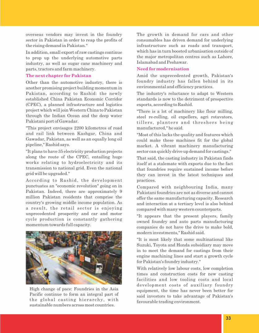
High change of pace: Foundries in the Asia Pacific continue to form an integral part of the g loba l cas t ing h ierarchy , wi th sustainable numbers across most countries.

34
over the country. To continue this endeavor a new foundry has been re-established having greater capacity cupola furnace of 10Ton/hour. He assured that as the tradition will continue to commit timely quality production in future, as well.
KS&EW is the only shipyard and oldest heavy engineering establishment of Pakistan catering for shipbuilding, ship repair and general / heavy engineering. It had a country's biggest foundry also catering the in-house and commercial needs of public/private sector. Nearly seven years ago, the then management decided to dismantle / dispose of the foundry being old and obsolete and primarily to vacate the site to give room for the mega project of Ship Lift and Transfer System speculating the future commercial needs of sh ipbui ld ing / repair and submarines construction. Realizing the present size of sugar vendor industry being around Rs. 22 billion, and considering the past pivotal role of KS&EW in producing sugar rolls and allied production activities, present management took initiative to re-establish foundry on other available area of KSEW, afresh, to again make the presence eminent in foundry sector of the country and to boost production activities of its large machine shop. Accordingly serious efforts have been made by all to revive this facility at Karachi Shipyard. A 10 ton/ hour cupola furnace, 5 ton and 1.5 ton induction furnaces and 300 kg non ferrous gas / oil fired furnace have been installed. All the equipments including furnaces have been manufactured in Pakistan to promote local industry. Cupola furnace shell has been fabricated in our yard. By Grace of Allah new foundry has started functioning in June this year.The first lot of 07 sugar rolls was handed over to M/S. Naudero Sugar Mill, in a gracious ceremony on 05 August 2015, attended by various sugar mills owners, representative of Pakistan Foundry Association, other stake holders and KS&EW high officials. In addition to this second lot of 20 sugar rolls will also be completed and delivered to respective clients, very soon.Rear Admiral Syed Hasan Nasir Shah HI(M),M.D. KS&EW, said in his welcome address that Karachi Shipyard & Engineering Works is pioneer in the construction of sugar mills on turn-key basis in Pakistan. Shipyard has also been supplying quality sugar rolls catering the seasonal demands of various sugar mills all
Re-establishing and Rehabilitating Foundry at
Karachi Shipyard & Engineering Works Ltd.


Recommended