EGR 334 ThermodynamicsChapter 9: Sections 1-2
Lecture 33: Gas Power Systems:The Otto Cycle Quiz Today?

Today’s main concepts:• Understand common terminology of gas power cycles.• Be able to explain the processes of the Otto Cycle• Be able to perform a 1st Law analysis of the Otto Cycle
and determine its thermal efficiency.• Be able to discuss limitations of the Otto cycle
compared to real spark ignition power systems.• Be able to state the assumptions of standard air
analysis.
Reading Assignment:
Homework Assignment:
Read Chapter 9, Sections 3-4
Problems from Chap 9: 1, 4, 11, 14

3
Two types of internal combustion engine• Spark Ignition (lower power & lighter)• Compression Ignition (spontaneous combustion)
TerminologyStroke : The distance the piston moves
in one directionTop Dead Center : The piston has
minimum volume at the top of the stroke.
Bottom Dead Center : The piston has maximum volume at the bottom of the stroke.
Clearance Volume : Min volDisplacement Volume : Max vol. – Min
vol.Compression Ratio: Max vol. / min vol.
Sec 9.1 : Introducing Engine Terminology

4
Four Stroke Cycle : Two revolutions : Combusts mix of hydrocarbons + O2
1.Intake stroke : fill cylinder•Spark cycle : fill with fuel and air mixture•Compression cycle : fill with air
2.Compression stroke : p , T , V , Win
•Spark cycle : spark near end of stroke•Compression cycle : inject fuel
Sec 9.1 : Introducing Engine Terminology
3. Power stroke : gas expands4. Exhaust stroke : spent gas
is exhausted
U--Tube video of 4 stroke:http://www.youtube.com/watch?v=2Yx32F1cncg

5
Two Stroke Cycle : Two revolutions 1. Power/Exhaust:•The piston is forced down•@ exhaust port, spent gas leaves•Piston continues down and compresses air/fuel in crank case•Compressed charge enters cylinder
2.Intake/Compression•Piston moves up compressing charge•Draws vacuum in crank case.
Sec 9.1 : Introducing Engine Terminology
Two Stroke Animation:http://library.thinkquest.org/C006011/english/sites/2_taktmotor.php3?v=2

6
Mean Effective Pressure (mep)
Sec 9.1 : Introducing Engine Terminology
net work from one cycle
displacement volumemep
Air –standard Analysis(A simplification used to allow for thermodynamic analysis)
Assumptions:-- Fixed amount of air modeled as closed system-- Air is treated as Ideal Gas-- Constant cp (cold air-standard)
-- Combustion is modeled as a heat transfer to system, Exhaust as heat flow out of system-- All processes internally reversible

7
Ideal Gas Model Review
2 22 2 1 1
1 1
( , ) ( , ) ln lnv
T vs T v s T v c R
T v
2 22 2 1 1
1 1
( , ) ( , ) ln lnp
T ps T p s T p c R
T p 2
2 2 1 1 2 11
( , ) ( , ) ( ) ( ) lno o ps T p s T p s T s T R
p
( 1) /
2 2
1 1
k kT p
T p
1
2 1
1 2
kT v
T v
2 1
1 2
kp v
p v
2 2
1 1
r
r
p p
p p2 2
1 1
r
r
v v
v v
Ideal Gas Model Relations:
where so values are found on Table A-22
pv RT pV mRTpV nRT
v vU m c dT mc T p pH m c dT mc T
p vc c R 1p
kRc
k
1v
Rc
k
Chap 3: Quality Polytropic Process
State Equation:
or look up values for k, cv, and cp on Table A-20
where
Energy Relationships:
Entropy Relationships:
Special case: isentropic process where s1 = s2 then
( vr and pr for use with Table A-22)( assuming constant specific heats)

8
Assumption: At top dead center, heat addition occurs instantaneously
Sec 9.2 : Air-Standard Otto Cycle
Otto Cycle: comprised of 4 internally reversible processes
Process 1 – 2 : Isentropic compression of air (compression stroke).
Process 2 – 3 : Constant volume heat transfer to the air from an external source while piston is at top dead center (ignition) Process 3 – 4 : Isentropic expansion (power stroke)Process 4 – 1 : Completes cycle by a constant volume process in which heat is rejected from the air while piston is at bottom dead center
exhaustcompression
ignitionpower
power
exhaust
compression
ignition

9Sec 9.2 : Air-Standard Otto Cycle
Otto Cycle analysis
Processes 1–2: ∆s = 0 and Q = 0
Closed system energy balance :
12 2 1W m u u
34 4 3W m u u
Processes 2–3 : ∆V = 0 and W = 0
23 3 2Q m u u
41 1 4Q m u u
12 34cycleW W W
23 3 2inQ Q m u u
U Q W
Process 3–4: ∆s = 0 and Q = 0
2 1 4 3m u u u u
Processes 4-1 : ∆V = 0 and W = 0
41 4 1outQ Q m u u

10Sec 9.2 : Air-Standard Otto Cycle
Otto Cycle Thermal Efficiency:
cycle in out
in in
W Q Q
Q Q
4 1
3 2
1u u
u u
3 2 4 1
3 2
u u u u
u u
Thermal Efficiency can also be related to the compression ratio:
displacement volume clearance volume
clearance volumer
3
4
2
1
V
V
V
Vr
displacement
clearance
1
11
kr
As the compression ration, r, , the efficiency, η,
11
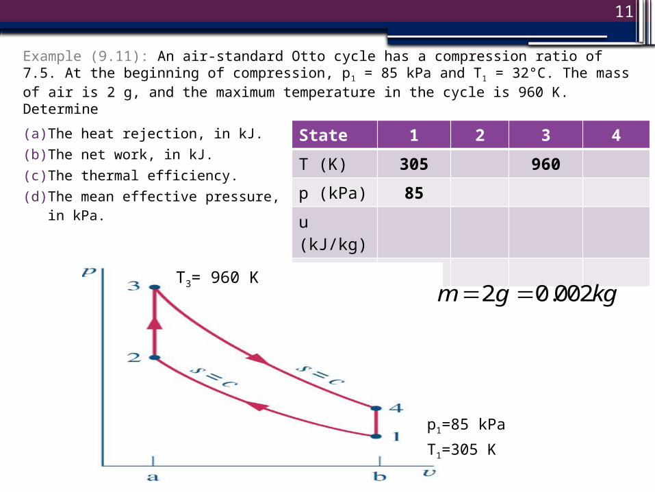
Example (9.11): An air-standard Otto cycle has a compression ratio of 7.5. At the beginning of compression, p1 = 85 kPa and T1 = 32°C. The mass of air is 2 g, and the maximum temperature in the cycle is 960 K. Determine
State 1 2 3 4
T (K) 305 960
p (kPa) 85
u (kJ/kg)
v
(a) The heat rejection, in kJ.(b) The net work, in kJ.(c) The thermal efficiency.(d) The mean effective
pressure, in kPa.
p1=85 kPa
T1=305 K
T3= 960 K2 0.002m g kg

12
Example (9.11):State 1 2 3 4
T (K) 305 960
p (kPa) 85
u (kJ/kg)
v
(a) The heat rejection, in kJ.(b) The net work, in kJ.(c) The thermal efficiency.(d) The mean effective
pressure, in kPa.
State 1: Using Ideal Gas Law:
State 2: Using compression ratio, ideal gas law, and Table A-22:
pv RT
311 2
1
(0.287 / )(305 )1.0298 /
(85 ) /
RT kJ kg K K kPa kN mv m kg
p kPa kN m kJ
1
2
vrv
312
1.02980.1373 /
7.5
vv m kg
r
1 217.67 /u kJ kg
and Table A-22:

13
Example (9.11):State 1 2 3 4
T (K) 305 960
p (kPa) 85
u (kJ/kg) 217.67
v 1.0298 0.1373
(a) The heat rejection, in kJ.(b) The net work, in kJ.(c) The thermal efficiency.(d) The mean effective
pressure, in kPa.
State 3: using v3 = v2, ideal gas law, and Table A22:
State 4: Using v4=v1:
33 0.1373 /v m kg
34 1 1.0298 /v v m kg
3 725.02 /u kJ kg
33 3 2
3
(0.287 / )(960 )2006.7
(0.1373 / ) /
RT kJ kg K K kPa kN mp kPa
v m kg kN m kJ

14
Example (9.11):State 1 2 3 4
T (K) 305 960
p (kPa) 85 2006.7
u (kJ/kg) 217.67 725.02
v 1.0298 0.1373
0.1373 1.0298
(a) The heat rejection, in kJ.(b) The net work, in kJ.(c) The thermal efficiency.(d) The mean effective
pressure(e) , in kPa.
also knowing for isentropic processes
then for isentropic process 1-2 using k = 1.361 and Table A-22:
2 458.55 /u kJ kg
1
2 1
1 2
kT v
T v
2 1
1 2
kp v
p v
1 0.361
2 1 305 7.5 631k
T T r K K
1.44 3
1 12006.7( ) 129.37.5k
p p kPar and for isentropic process 3-4:
0.3611
4 31 1960 4647.5
k
T T K Kr
1.3612 1 85(7.5) 1319
kp p r kPa
4 328.5 /u kJ kg
15
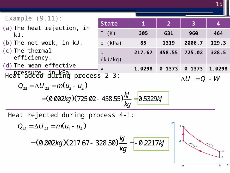
Example (9.11):
(a) The heat rejection, in kJ.(b) The net work, in kJ.(c) The thermal efficiency.(d) The mean effective
pressure, in kPa.
Heat added during process 2-3:
Heat rejected during process 4-1:
41 41 1 4Q U m u u
23 23 3 2Q U m u u
0.002 725.02 458.55 0.5329kJ
kg kJkg
U Q W
0.002 217.67 328.50 0.2217kJ
kg kJkg
State 1 2 3 4
T (K) 305 631 960 464
p (kPa) 85 1319 2006.7 129.3
u (kJ/kg) 217.67 458.55
725.02 328.5
v 1.0298 0.1373
0.1373 1.0298

16
Example (9.11):State 1 2 3 4
T (K) 305 631 960 464
p (kPa) 85 1319 2006.7 129.3
u (kJ/kg) 217.67 458.55
725.02 328.5
v 1.0298 0.1373
0.1373 1.0298
(a) The heat rejection, in kJ.(b) The net work, in kJ.(c) The thermal efficiency.(d) The mean effective
pressure, in kPa.
Net Work over the cycle:
Cycle Efficiency:
23 41cycle in outW Q Q Q Q
(0.5329) ( 0.2217) 0.3112kJ
0.31120.5839
0.5329cycle
in
W kJ
Q kJ
Compare to
1 0.4
1 11 1 0.553
7.5kr

17
Example (9.11):State 1 2 3 4
T (K) 305 631 960 464
p (kPa) 85 1319 2006.7 129.3
u (kJ/kg) 217.67 458.55
725.02 328.5
v 1.0298 0.1373
0.1373 1.0298
(a) The heat rejection, in kJ.(b) The net work, in kJ.(c) The thermal efficiency.(d) The mean effective
pressure, in kPa.
Mean Effective Pressure:
where
1 2
net work from one cycle
displacement volumecycleW
mepV V
3 31 1 0.002 (1.0298 / ) 0.0020596V mv kg m kg m
3 32 2 0.002 (0.1373 / ) 0.0002746V mv kg m kg m
3 2
0.3112174.34
(0.0020596 - 0.0002746) /
kJ kN m kPamep kPa
m kJ kN m

18
End of Slides for Lecture 33
Recommended