http://www.iaeme.com/IJMET/index.asp 392 [email protected]
International Journal of Mechanical Engineering and Technology (IJMET)
Volume 9, Issue 3, March 2018, pp. 392–404 Article ID: IJMET_09_03_039
Available online at http://www.iaeme.com/IJMET/issues.asp?JType=IJMET&VType=9&IType=3
ISSN Print: 0976-6340 and ISSN Online: 0976-6359
© IAEME Publication Scopus Indexed
EFFECT OF PRETREATMENT METHODS,
CHAMBER PRESSURE AND SUBSTRATE
TEMPERATURE ON MORPHOLOGY,
QUALITY, ADHESION AND CUTTING
PERFORMANCE OF HFCVD DIAMOND
COATED TOOLS IN MACHINING ALUMINIUM
ON CEMENTED CARBIDE INSERTS
Dilip Kumar Sahu
Department of Mechanical Engineering, KGRCE&T, Moinabad, India
Saroj Kumar Sarangi
Department of Mechanical Engineering, VSSUT, Burla, Sambalpur, India
Kakarla Udaya Sri
Department of Mechanical Engineering, KGRCE&T, Moinabad, India
ABSTRACT
The wide applications of aluminium in different industries have increased the
necessity for researching on suitable cutting tool. It is observed that, comparing to
ferrous materials; dry machining of aluminium, exhibits a greater challenge in view of
heavy material built-up at the cutting edge. This not only enhances cutting force but
also causes poor quality surface finish on the workpiece.
This paper thoroughly investigated the effect of substrate treatments, micro
structure, adhesive toughness and cutting force of Hot Filament Chemical Vapour
Deposition (HFCVD) diamond coating on uncoated carbide cutting inserts
(94%WC+6%Co). To restrict the formation of non-diamond carbon phases, such as
graphite, and to improve the adhesion between diamond and WC substrates, etching
with a combination of diluted HCL and HNO3 are used as substrate pretreatments.
The pressure in the CVD chamber are set at 0.666, 1.333, 2.666 and 3.999 kPa and
the substrate temperatures are kept at 650, 700, 750 0C while maintaining the filament
temperature at 2100 0C. Characterization and purity (sp
3 / sp
2) of the obtained
coatings are duly evaluated by Scanning Electron Microscope (SEM) and Raman
Spectroscopy. The mechanical characterization of the coating is investigated by
Rockwell indentation test under loads of 294 N, 588 N and 980 N to assess the
coating-substrate adhesion.
Dilip Kumar Sahu, Saroj Kumar Sarangi and Kakarla Udaya Sri
http://www.iaeme.com/IJMET/index.asp 393 [email protected]
It is observed that the deposition pressure at 2.666 and 3.999 kPa and substrate
temperature at 700 0C, coating with (111) habits is mostly preferred to achieve
maximum coating substrate adhesion. These results suggest that during dry
machining, compare to uncoated tool, a 4-5 µm HFCVD diamond coating exhibits
remarkable inertness towards aluminium leading to substantial reduction of cutting
force and improvement of work-piece surface finish.
Keywords: HFCVD diamond, Coating, Morphology, Adhesion, Machining
Cite this Article: Dilip Kumar Sahu, Saroj Kumar Sarangi and Kakarla Udaya Sri,
Effect of Pretreatment Methods, Chamber Pressure and Substrate Temperature on
Morphology, Quality, Adhesion and Cutting Performance of HFCVD Diamond Coated
Tools in Machining Aluminium on Cemented Carbide Inserts, International Journal of
Mechanical Engineering and Technology 9(3), 2018. pp. 392–404.
http://www.iaeme.com/IJMET/issues.asp?JType=IJMET&VType=9&IType=3
1. INTRODUCTION
In the field of innovative cutting tool mechanism, the use of Chemical Vapour Deposition
(CVD) diamond coating on tungsten carbide inserts is succeeded to attract more attention in
world over. But more understanding is needed to analyze the relation between deposition
parameters and the vital properties of diamond film [1-2].
In recent years, with the development of different coated tools, the efficiency of cutting
processes has been improved. Diamond coating has proved its superiority in the case of non-
ferrous metal, such as aluminium and magnesium. It results in good surface finish, lesser edge
formation, chemical inertness and high wear resistance [3-6]. Effort has been made to
improvise the adhesion of diamond coatings in substrate materials and further to optimize the
interface strength of tool performance; chemical and mechanical substrate pretreatments are
being done [7-8].
Cemented tungsten carbide (WC-Co) is considered as one of the most appropriate
substrate material in the production of diamond coated tools. Though cobalt acts as a binder
which provides additional toughness to tool, but it becomes antagonistic to diamond adhesion
[9-11]. It is understood from the phase diagram of Co-C system that under typical diamond
CVD temperatures (700-10000C), carbon is soluble in Co in the range of 0.2-0.3 wt % C
[12].
In the preliminary stage of CVD process, WC-Co is succumbed to a radical rich atmosphere
of hydrocarbon and carbon species start to diffuse into the greater part of the binder stage till
the solubility of carbon exceeds the partially filled 3d shell transition metal, cobalt. The Co
acts like a catalytic agent in the formation of graphite [13]. This restricts the deposition of
adherent diamond coatings onto untreated WC-Co tools. Therefore, it is necessary to remove
cobalt from the surface of the tools. Several literatures [14-17] have established the reports
that the early formation of sp2-carbon layer at the substrate surface is detrimental to the
growth of diamond in the later stage.
The growth of polycrystalline diamond coatings on several substrates using CVD
technique are presented in different research papers [18-20]. Polycrystalline diamond is
further categorized into micro, nano and ultra-nano crystalline depending upon the average
grain size. Similarly the properties of different coatings are to vary with degrees similar to
single crystal diamond [18-21].
Generally, diamond coatings on cutting tools are employed to increase their performances.
The increase of performance for the conventional (macroscopic) size cutting tools using these
coatings are necessitated for the different types of reasons which are listed below:
Effect of Pretreatment Methods, Chamber Pressure and Substrate Temperature on Morphology,
Quality, Adhesion and Cutting Performance of HFCVD Diamond Coated Tools in Machining
Aluminium on Cemented Carbide Inserts
http://www.iaeme.com/IJMET/index.asp 394 [email protected]
Extremely high hardness (80-100GPa) which helps reduce tools wear [18-23].
Low coefficients of friction against various work-piece materials, which decreases
cutting and thrust forces and also reduced heat production [24].
Chemical inertness and low adhesion to must work-piece materials, which prevents
built-up-edge (the build-up of work-piece material on the tool rake face), dead metal
zones and clogging of flutes [25].
2. EXPERIMENTAL PROCEDURES AND CONDITIONS
The substrates used for CVD diamond deposition were cemented carbide turning inserts of
geometry SPUN120308, ISO K grade containing 6wt% cobalt. Prior to deposition the samples
were cleaned with trichloroethylene and acetone followed by isopropyl alcohol to remove
contaminates from the surface. Samples were etched with HCl+HNO3+H2O (1:1:1) for 15
minutes ultrasonically at room temperature to change the chemical composition and to
roughen the surface. Then the inserts were seeded with diamond powder (0.2-1 µm) by
ultrasonic agitation for two minutes in solvent 2-propanal, so that the seeds would enter the
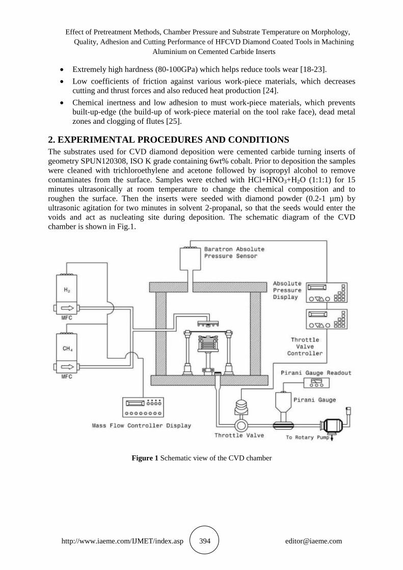
voids and act as nucleating site during deposition. The schematic diagram of the CVD
chamber is shown in Fig.1.
Figure 1 Schematic view of the CVD chamber
Dilip Kumar Sahu, Saroj Kumar Sarangi and Kakarla Udaya Sri
http://www.iaeme.com/IJMET/index.asp 395 [email protected]
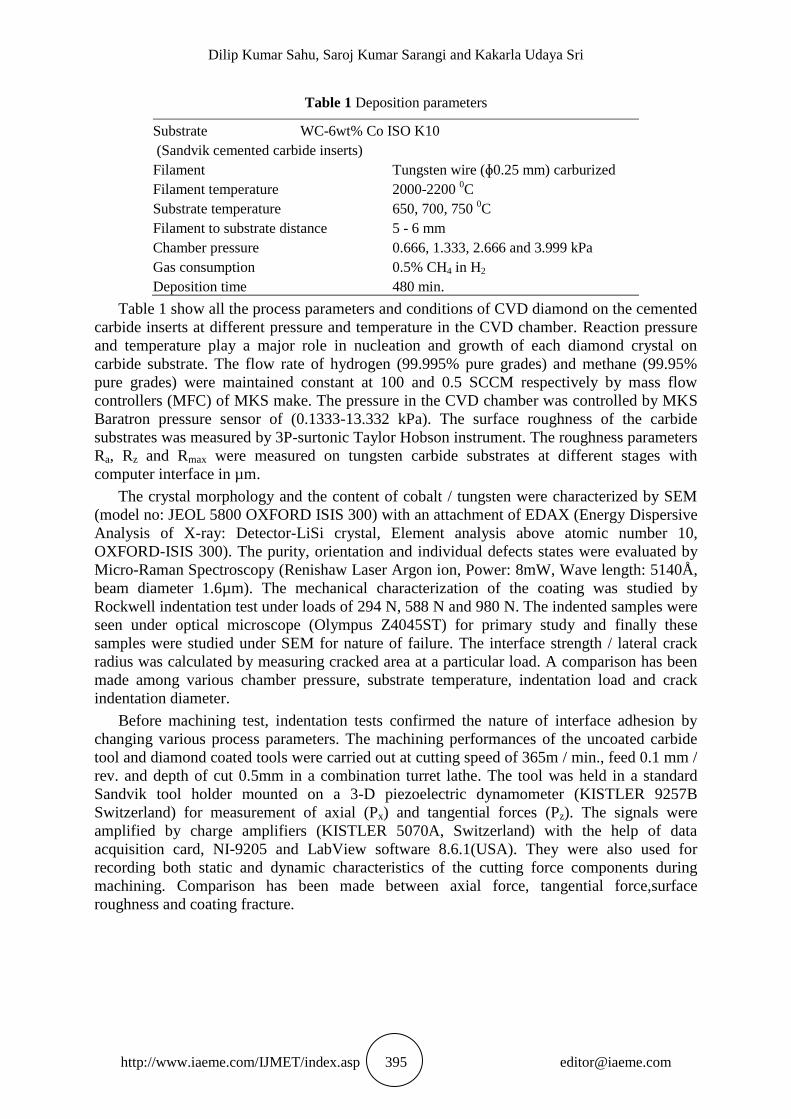
Table 1 Deposition parameters
Substrate WC-6wt% Co ISO K10
(Sandvik cemented carbide inserts)
Filament Tungsten wire (ɸ0.25 mm) carburized
Filament temperature 2000-2200 0C
Substrate temperature 650, 700, 750 0C
Filament to substrate distance 5 - 6 mm
Chamber pressure 0.666, 1.333, 2.666 and 3.999 kPa
Gas consumption 0.5% CH4 in H2
Deposition time 480 min.
Table 1 show all the process parameters and conditions of CVD diamond on the cemented
carbide inserts at different pressure and temperature in the CVD chamber. Reaction pressure
and temperature play a major role in nucleation and growth of each diamond crystal on
carbide substrate. The flow rate of hydrogen (99.995% pure grades) and methane (99.95%
pure grades) were maintained constant at 100 and 0.5 SCCM respectively by mass flow
controllers (MFC) of MKS make. The pressure in the CVD chamber was controlled by MKS
Baratron pressure sensor of (0.1333-13.332 kPa). The surface roughness of the carbide
substrates was measured by 3P-surtonic Taylor Hobson instrument. The roughness parameters
Ra, Rz and Rmax were measured on tungsten carbide substrates at different stages with
computer interface in µm.
The crystal morphology and the content of cobalt / tungsten were characterized by SEM
(model no: JEOL 5800 OXFORD ISIS 300) with an attachment of EDAX (Energy Dispersive
Analysis of X-ray: Detector-LiSi crystal, Element analysis above atomic number 10,
OXFORD-ISIS 300). The purity, orientation and individual defects states were evaluated by
Micro-Raman Spectroscopy (Renishaw Laser Argon ion, Power: 8mW, Wave length: 5140Å,
beam diameter 1.6µm). The mechanical characterization of the coating was studied by
Rockwell indentation test under loads of 294 N, 588 N and 980 N. The indented samples were
seen under optical microscope (Olympus Z4045ST) for primary study and finally these
samples were studied under SEM for nature of failure. The interface strength / lateral crack
radius was calculated by measuring cracked area at a particular load. A comparison has been
made among various chamber pressure, substrate temperature, indentation load and crack
indentation diameter.
Before machining test, indentation tests confirmed the nature of interface adhesion by
changing various process parameters. The machining performances of the uncoated carbide
tool and diamond coated tools were carried out at cutting speed of 365m / min., feed 0.1 mm /
rev. and depth of cut 0.5mm in a combination turret lathe. The tool was held in a standard
Sandvik tool holder mounted on a 3-D piezoelectric dynamometer (KISTLER 9257B
Switzerland) for measurement of axial (Px) and tangential forces (Pz). The signals were
amplified by charge amplifiers (KISTLER 5070A, Switzerland) with the help of data
acquisition card, NI-9205 and LabView software 8.6.1(USA). They were also used for
recording both static and dynamic characteristics of the cutting force components during
machining. Comparison has been made between axial force, tangential force,surface
roughness and coating fracture.
Effect of Pretreatment Methods, Chamber Pressure and Substrate Temperature on Morphology,
Quality, Adhesion and Cutting Performance of HFCVD Diamond Coated Tools in Machining
Aluminium on Cemented Carbide Inserts
http://www.iaeme.com/IJMET/index.asp 396 [email protected]
3. RESULTS AND DISCUSSION
3.1. On Substrate Treatment
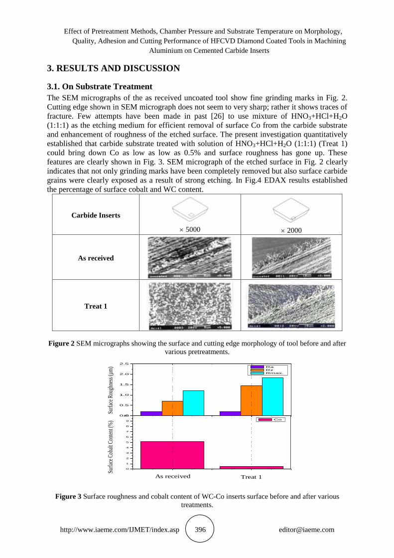
The SEM micrographs of the as received uncoated tool show fine grinding marks in Fig. 2.
Cutting edge shown in SEM micrograph does not seem to very sharp; rather it shows traces of
fracture. Few attempts have been made in past [26] to use mixture of HNO3+HCl+H2O
(1:1:1) as the etching medium for efficient removal of surface Co from the carbide substrate
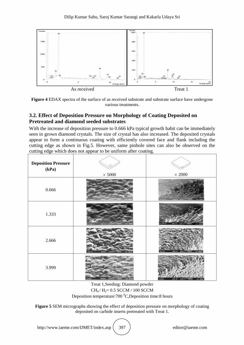
and enhancement of roughness of the etched surface. The present investigation quantitatively
established that carbide substrate treated with solution of HNO3+HCl+H2O (1:1:1) (Treat 1)
could bring down Co as low as low as 0.5% and surface roughness has gone up. These
features are clearly shown in Fig. 3. SEM micrograph of the etched surface in Fig. 2 clearly
indicates that not only grinding marks have been completely removed but also surface carbide
grains were clearly exposed as a result of strong etching. In Fig.4 EDAX results established
the percentage of surface cobalt and WC content.
Carbide Inserts
5000
2000
As received
Treat 1
Figure 2 SEM micrographs showing the surface and cutting edge morphology of tool before and after
various pretreatments.
Figure 3 Surface roughness and cobalt content of WC-Co inserts surface before and after various
treatments.
Treat 1 As received
Sur
face
Cob
alt C
onte
nt (%
) S
urfa
ce R
ough
ness
(µm
)
0.0
0.5
1.0
1.5
2.0
2.5
Ra
Rz
Rmax.
0
1
2
3
4
5
6
7
8
9
10
Co
Dilip Kumar Sahu, Saroj Kumar Sarangi and Kakarla Udaya Sri
http://www.iaeme.com/IJMET/index.asp 397 [email protected]
As received Treat 1
Figure 4 EDAX spectra of the surface of as received substrate and substrate surface have undergone
various treatments.
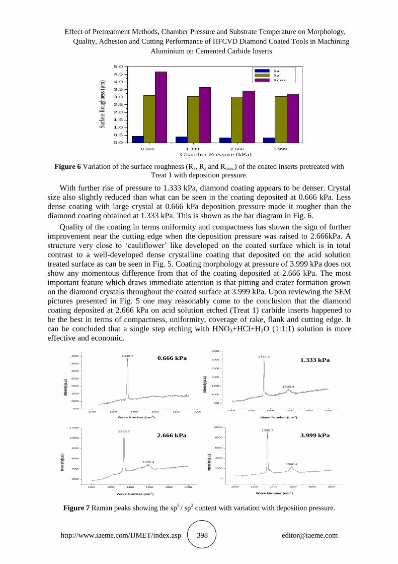
3.2. Effect of Deposition Pressure on Morphology of Coating Deposited on
Pretreated and diamond seeded substrates
With the increase of deposition pressure to 0.666 kPa typical growth habit can be immediately
seen in grown diamond crystals. The size of crystal has also increased. The deposited crystals
appear to form a continuous coating with efficiently covered face and flank including the
cutting edge as shown in Fig.5. However, same pinhole sites can also be observed on the
cutting edge which does not appear to be uniform after coating.
Deposition Pressure
(kPa)
5000
2000
0.666
1.333
2.666
3.999
Treat 1,Seeding: Diamond powder
CH4 / H2= 0.5 SCCM / 100 SCCM
Deposition temperature:700 0C,Deposition time:8 hours
Figure 5 SEM micrographs showing the effect of deposition pressure on morphology of coating
deposited on carbide inserts pretreated with Treat 1.
Effect of Pretreatment Methods, Chamber Pressure and Substrate Temperature on Morphology,
Quality, Adhesion and Cutting Performance of HFCVD Diamond Coated Tools in Machining
Aluminium on Cemented Carbide Inserts
http://www.iaeme.com/IJMET/index.asp 398 [email protected]
Figure 6 Variation of the surface roughness (Ra, Rz and Rmax.) of the coated inserts pretreated with
Treat 1 with deposition pressure.
With further rise of pressure to 1.333 kPa, diamond coating appears to be denser. Crystal
size also slightly reduced than what can be seen in the coating deposited at 0.666 kPa. Less
dense coating with large crystal at 0.666 kPa deposition pressure made it rougher than the
diamond coating obtained at 1.333 kPa. This is shown as the bar diagram in Fig. 6.
Quality of the coating in terms uniformity and compactness has shown the sign of further
improvement near the cutting edge when the deposition pressure was raised to 2.666kPa. A
structure very close to ‘cauliflower’ like developed on the coated surface which is in total
contrast to a well-developed dense crystalline coating that deposited on the acid solution
treated surface as can be seen in Fig. 5. Coating morphology at pressure of 3.999 kPa does not
show any momentous difference from that of the coating deposited at 2.666 kPa. The most
important feature which draws immediate attention is that pitting and crater formation grown
on the diamond crystals throughout the coated surface at 3.999 kPa. Upon reviewing the SEM
pictures presented in Fig. 5 one may reasonably come to the conclusion that the diamond
coating deposited at 2.666 kPa on acid solution etched (Treat 1) carbide inserts happened to
be the best in terms of compactness, uniformity, coverage of rake, flank and cutting edge. It
can be concluded that a single step etching with HNO3+HCl+H2O (1:1:1) solution is more
effective and economic.
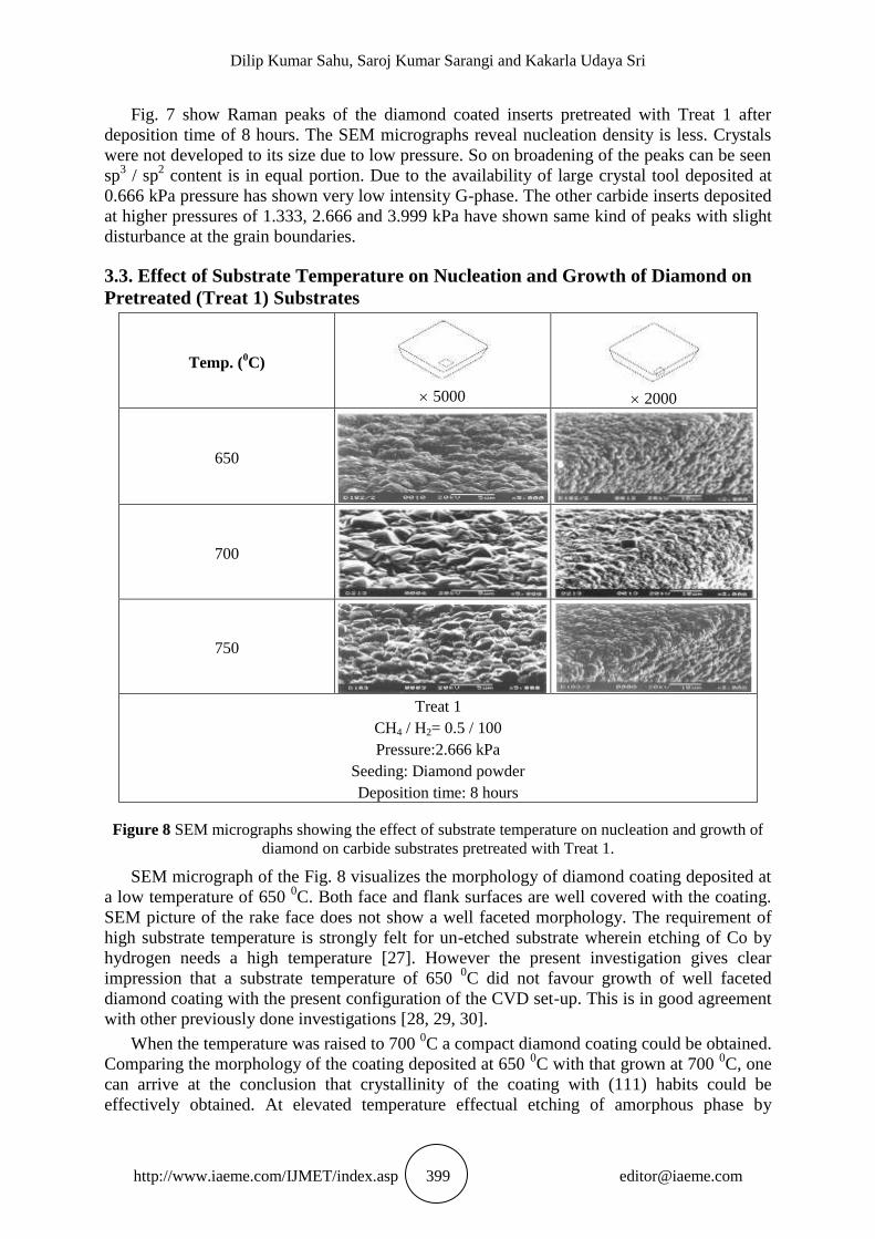
Figure 7 Raman peaks showing the sp3 / sp
2 content with variation with deposition pressure.
0.0
0.5
1.0
1.5
2.0
2.5
3.0
3.5
4.0
4.5
5.0 Ra
Rz
Rmax.
Surfa
ce R
ough
ness
(µm
)
0.666 1.333 2.666 3.999
Chamber Pressure (kPa)
Ra
Rz
Rmax.
1335.4 1334.2
1586.4
1335.7
1586.4
1335.7
1586.4
1000 1200 1400 1600 1800 2000
500
1000
1500
2000
2500
3000
3500
4000
5 Torr
Inte
nsity
(a.u
.)
Wave Number (cm-1
)
1000 1200 1400 1600 1800 2000
500
1000
1500
2000
2500
3000
3500
20 Torr
10 Torr
Inte
nsity
(a.u
.)
Wave Number (cm-1
)
1000 1200 1400 1600 1800 2000
2000
4000
6000
8000
10000
12000
Inte
nsity
(a.u
.)
Wave Number (cm-1
)
1000 1200 1400 1600 1800 2000
0
2000
4000
6000
8000
10000
30 Torr
Inte
nsity
(a.u
.)
Wave Number (cm-1
)
0.666 kPa
1.333 kPa
2.666 kPa
3.999 kPa
Dilip Kumar Sahu, Saroj Kumar Sarangi and Kakarla Udaya Sri
http://www.iaeme.com/IJMET/index.asp 399 [email protected]
Fig. 7 show Raman peaks of the diamond coated inserts pretreated with Treat 1 after
deposition time of 8 hours. The SEM micrographs reveal nucleation density is less. Crystals
were not developed to its size due to low pressure. So on broadening of the peaks can be seen
sp3 / sp
2 content is in equal portion. Due to the availability of large crystal tool deposited at
0.666 kPa pressure has shown very low intensity G-phase. The other carbide inserts deposited
at higher pressures of 1.333, 2.666 and 3.999 kPa have shown same kind of peaks with slight
disturbance at the grain boundaries.
3.3. Effect of Substrate Temperature on Nucleation and Growth of Diamond on
Pretreated (Treat 1) Substrates
Temp. (0C)
5000
2000
650
700
750
Treat 1
CH4 / H2= 0.5 / 100
Pressure:2.666 kPa
Seeding: Diamond powder
Deposition time: 8 hours
Figure 8 SEM micrographs showing the effect of substrate temperature on nucleation and growth of
diamond on carbide substrates pretreated with Treat 1.
SEM micrograph of the Fig. 8 visualizes the morphology of diamond coating deposited at
a low temperature of 650 0C. Both face and flank surfaces are well covered with the coating.
SEM picture of the rake face does not show a well faceted morphology. The requirement of
high substrate temperature is strongly felt for un-etched substrate wherein etching of Co by
hydrogen needs a high temperature [27]. However the present investigation gives clear
impression that a substrate temperature of 650 0C did not favour growth of well faceted
diamond coating with the present configuration of the CVD set-up. This is in good agreement
with other previously done investigations [28, 29, 30].
When the temperature was raised to 700 0C a compact diamond coating could be obtained.
Comparing the morphology of the coating deposited at 650 0C with that grown at 700
0C, one
can arrive at the conclusion that crystallinity of the coating with (111) habits could be
effectively obtained. At elevated temperature effectual etching of amorphous phase by
Effect of Pretreatment Methods, Chamber Pressure and Substrate Temperature on Morphology,
Quality, Adhesion and Cutting Performance of HFCVD Diamond Coated Tools in Machining
Aluminium on Cemented Carbide Inserts
http://www.iaeme.com/IJMET/index.asp 400 [email protected]
hydrogen could lead to very good crystallinity with high quality diamond. At elevated
substrate temperature of 750 0C the coating effectively covered the rake, cutting edge and the
flank. However, the cutting edge shows same ‘pin hole’ sites. Average size of crystals appears
to be slightly less than that obtained at 700 0C. Hence at 750
0C the effect of atomic hydrogen
on etching of not only amorphous phase but also diamond may be considered.
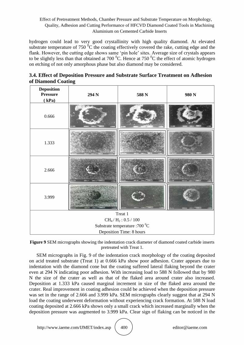
3.4. Effect of Deposition Pressure and Substrate Surface Treatment on Adhesion
of Diamond Coating
Deposition
Pressure
( kPa)
294 N 588 N 980 N
0.666
1.333
2.666
3.999
Treat 1
CH4 / H2 : 0.5 / 100
Substrate temperature :700 0C
Deposition Time: 8 hours
Figure 9 SEM micrographs showing the indentation crack diameter of diamond coated carbide inserts
pretreated with Treat 1.
SEM micrographs in Fig. 9 of the indentation crack morphology of the coating deposited
on acid treated substrate (Treat 1) at 0.666 kPa show poor adhesion. Crater appears due to
indentation with the diamond cone but the coating suffered lateral flaking beyond the crater
even at 294 N indicating poor adhesion. With increasing load to 588 N followed that by 980
N the size of the crater as well as that of the flaked area around crater also increased.
Deposition at 1.333 kPa caused marginal increment in size of the flaked area around the
crater. Real improvement in coating adhesion could be achieved when the deposition pressure
was set in the range of 2.666 and 3.999 kPa. SEM micrographs clearly suggest that at 294 N
load the coating underwent deformation without experiencing crack formation. At 588 N load
coating deposited at 2.666 kPa shows only a small crack which increased marginally when the
deposition pressure was augmented to 3.999 kPa. Clear sign of flaking can be noticed in the
Dilip Kumar Sahu, Saroj Kumar Sarangi and Kakarla Udaya Sri
http://www.iaeme.com/IJMET/index.asp 401 [email protected]
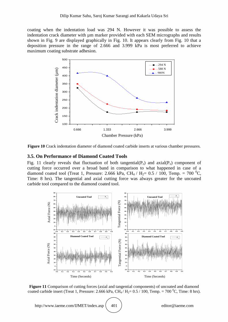
coating when the indentation load was 294 N. However it was possible to assess the
indentation crack diameter with µm marker provided with each SEM micrographs and results
shown in Fig. 9 are displayed graphically in Fig. 10. It appears clearly from Fig. 10 that a
deposition pressure in the range of 2.666 and 3.999 kPa is most preferred to achieve
maximum coating substrate adhesion.
Figure 10 Crack indentation diameter of diamond coated carbide inserts at various chamber pressures.
3.5. On Performance of Diamond Coated Tools
Fig. 11 clearly reveals that fluctuation of both tangential(Pz) and axial(Px) component of
cutting force occurred over a broad band in comparison to what happened in case of a
diamond coated tool (Treat 1, Pressure: 2.666 kPa, CH4 / H2= 0.5 / 100, Temp. = 700 0C,
Time: 8 hrs). The tangential and axial cutting force was always greater for the uncoated
carbide tool compared to the diamond coated tool.
Figure 11 Comparison of cutting forces (axial and tangential components) of uncoated and diamond
coated carbide insert (Treat 1, Pressure: 2.666 kPa, CH4 / H2= 0.5 / 100, Temp. = 700 0C, Time: 8 hrs).
0.666 1.333 2.666 3.999
Chamber Pressure (kPa)
C
rack
inden
tati
on d
iam
eter
(µ
m)
100
150
200
250
300
350
400
450
500
30Kgf
60Kgf
100Kgf
294 N
588 N
980N
4.0 4.1 4.2 4.3 4.4 4.5 4.6 4.7 4.8 4.9 5.0
-10
0
10
20
30
40
50
60
70
80
90
Uncoated
Axi
al F
orc
e (N
)
Time in seconds
PX
4.0 4.1 4.2 4.3 4.4 4.5 4.6 4.7 4.8 4.9 5.0
-10
0
10
20
30
40
50
60
70
80
90
Uncoated
Time in seconds
Tan
gen
tial
Fo
rce
(N)
PZ
4.0 4.1 4.2 4.3 4.4 4.5 4.6 4.7 4.8 4.9 5.0
-10
0
10
20
30
40
50
60
70
80
90
D143
Time in seconds
Axi
al F
orc
e (N
)
PX
4.0 4.1 4.2 4.3 4.4 4.5 4.6 4.7 4.8 4.9 5.0
-10
0
10
20
30
40
50
60
70
80
90
D143
Tan
gen
tial
Fo
rce(
N)
Time in seconds
PZ
A
xia
l F
orc
e (N
) A
xia
l F
orc
e (N
)
Uncoated Tool Uncoated Tool
Diamond Coated Tool Diamond Coated Tool
Time (Seconds) Time (Seconds)
T
angen
tial
Forc
e (N
)
Tan
gen
tial
Forc
e (N
)
Effect of Pretreatment Methods, Chamber Pressure and Substrate Temperature on Morphology,
Quality, Adhesion and Cutting Performance of HFCVD Diamond Coated Tools in Machining
Aluminium on Cemented Carbide Inserts
http://www.iaeme.com/IJMET/index.asp 402 [email protected]
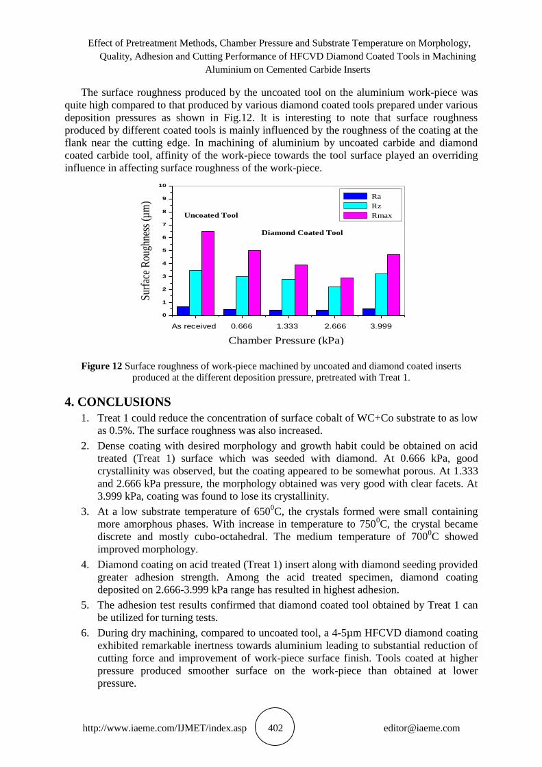
The surface roughness produced by the uncoated tool on the aluminium work-piece was
quite high compared to that produced by various diamond coated tools prepared under various
deposition pressures as shown in Fig.12. It is interesting to note that surface roughness
produced by different coated tools is mainly influenced by the roughness of the coating at the
flank near the cutting edge. In machining of aluminium by uncoated carbide and diamond
coated carbide tool, affinity of the work-piece towards the tool surface played an overriding
influence in affecting surface roughness of the work-piece.
Figure 12 Surface roughness of work-piece machined by uncoated and diamond coated inserts
produced at the different deposition pressure, pretreated with Treat 1.
4. CONCLUSIONS
1. Treat 1 could reduce the concentration of surface cobalt of WC+Co substrate to as low
as 0.5%. The surface roughness was also increased.
2. Dense coating with desired morphology and growth habit could be obtained on acid
treated (Treat 1) surface which was seeded with diamond. At 0.666 kPa, good
crystallinity was observed, but the coating appeared to be somewhat porous. At 1.333
and 2.666 kPa pressure, the morphology obtained was very good with clear facets. At
3.999 kPa, coating was found to lose its crystallinity.
3. At a low substrate temperature of 6500C, the crystals formed were small containing
more amorphous phases. With increase in temperature to 7500C, the crystal became
discrete and mostly cubo-octahedral. The medium temperature of 7000C showed
improved morphology.
4. Diamond coating on acid treated (Treat 1) insert along with diamond seeding provided
greater adhesion strength. Among the acid treated specimen, diamond coating
deposited on 2.666-3.999 kPa range has resulted in highest adhesion.
5. The adhesion test results confirmed that diamond coated tool obtained by Treat 1 can
be utilized for turning tests.
6. During dry machining, compared to uncoated tool, a 4-5µm HFCVD diamond coating
exhibited remarkable inertness towards aluminium leading to substantial reduction of
cutting force and improvement of work-piece surface finish. Tools coated at higher
pressure produced smoother surface on the work-piece than obtained at lower
pressure.
Uncoated Tool
Diamond Coated Tool
0
1
2
3
4
5
6
7
8
9
10
As received 5 10 20 30
Surf
ace
roug
hnes
s (
m)
Chamber pressure (Torr)
Ra
Rz
Rmax.
Ra
Rz
Rmax
S
urfa
ce R
ough
ness
(µ
m)
As received 0.666 1.333 2.666 3.999
Chamber Pressure (kPa)
Dilip Kumar Sahu, Saroj Kumar Sarangi and Kakarla Udaya Sri
http://www.iaeme.com/IJMET/index.asp 403 [email protected]
REFERENCES
[1] Hintermann H E and Chattopadhyay A K. Low Pressure Synthesis of Diamond Coatings.
CIRP Annals - Manufacturing Technology.1993; 42 (2): 769-783.
[2] Spitsyn B V, Boilov L L and Derguin B V. Vapor growth of diamond on diamond and
other surfaces. Journal of Crystal Growth.1981; 52 (2): 219-226.
[3] Leyendecker T, Lemmer O, Jürgens A, Esser S andEbberink J. Industrial application of
crystalline diamond-coated tools. Surface and Coatings Technology.1991;48 (3): 253-260.
[4] Zhu W, McCune R C, deVries J E, Tamor M A and Simon Ng K Y. Investigation of
adhesion of diamond films on Mo, W and carburized W substrates. Diamond and Related
Materials.1995; 4 (3):220-233.
[5] ReineckI and Sjostrand M E. Diamond coated cutting tools. International Journal of
Refractory Metals and Hard Materials.1996; 14 (1-3): 187-193.
[6] Tonshoff H K and Winkler J.The influence of tool coatings in machining of magnesium.
Surface and Coatings Technology.1997; 94–95: 610-616.
[7] Deuerler F, van den Berg, H, Tabersky R, Freundlieb, A Pies, M, and Buck V.
Pretreatment of substrate surface for improved adhesion of diamond films on hard metal
cutting tools. Diamond and Related Materials.1996; 5 (12):1478-1489.
[8] Tonshoff H K, Mohlfeld A, Gey C and Winkler J. Surface modification of cemented
carbide cutting tools for improved adhesion of diamond coatings. Surface and Coatings
Technology. 1998; 108-109:543-550.
[9] Haubner R, Lindlbauer A and Lux B. Diamond deposition on chromium, cobalt and nickel
substrates by microwave plasma chemical vapour deposition. Diamond and Related
Materials 1993; 2 (12):1505-1515.
[10] Nesládek M, Vandierendonck K, Quaeyhaegens C, Kerkhofs M. andStals L.M. Adhesion
of diamond coatings on cemented carbides. Thin Solid Films.1995; 270 (1-2):84-188.
[11] Inspektor A, Oles E J and Bauer C. E. Theory and practice in diamond coated metal-
cutting tools. International Journal of Refractory Metals and Hard Materials. 1997;
15 (1-3): 49-56.
[12] Baker (Ed.) H. Alloy Phase Diagrams. ASM Handbook, ASM International Metals Park,
Ohio, USA. 1997; Vol. 3.
[13] Chen X. and Narayan J. Effect of the chemical nature of transition‐metal substrates on
chemical‐vapor deposition of diamond. Journal of Applied Physics.1993; 74: 4168-4173.
[14] Shibuki K, Yagi M, Saijo K and Takatsu S. Adhesion strength of diamond films on
cemented carbide substrates. Surface and Coatings Technology.1988; 36(1-2): 95-302.
[15] Huang T H and Kuo C T. Wear behaviour of various diamond-coated cutting tools under
different deposition conditions. Diamond and Related Materials, 1993; 2(5-7): 928-932.
[16] Itoh H, Osaki T, Iwahara H and Sakamoto H. Nucleation control of diamond synthesized
by microwave plasma CVD on cemented carbide substrate. Journal of Materials
Science.1991; 26(14):3763–3768.
[17] Inspektor A, Bauer C E and Oles E J. Superhard coatings for metal cutting applications.
Surface and Coatings Technology.1994; 68-69: 359-368.
[18] Hay R A (Ed.).The New Diamond Technology and its Applications to Cutting Tools.
Ceramic Cutting Tools. Vol.11, William Andrew Publishing / Noyes, Norwich, NY,
(1994); p. 305.
[19] Schwarz J, Meteva K, Grigat A, Schubnov A, Metev S and Vollertsen F. Synthesis of
diamond coatings on tungsten carbide with photon plasmatron. Diamond and Related
Materials.2005; 14(3-7): 302-307.
[20] Ueng H Y and Guo C T. Diamond-like carbon coatings on micro-drill using an ECR-CVD
system. Applied Surface Science.2005; 249(1–4): 246–256.
Effect of Pretreatment Methods, Chamber Pressure and Substrate Temperature on Morphology,
Quality, Adhesion and Cutting Performance of HFCVD Diamond Coated Tools in Machining
Aluminium on Cemented Carbide Inserts
http://www.iaeme.com/IJMET/index.asp 404 [email protected]
[21] Chang C, Liao Y, Wang G Z, Ma Y R and Fang (Eds) R C. Crystal Growth Technology,
Springer, Heidelberg. 2003; 4, p. 93, CVD Diamond Growth.
[22] Jackson M J, Gill M D H, Sein H and Ahmed W. Manufacture of diamond-coated cutting
tools for micromachining applications. Proceedings of IMechE Part L: Journal of
Materials: Design and Applications.2003; 217: 77-83.
[23] Sein H, Ahmed W, Jackson M, Woodwards R and Polini R. Performance and
characterisation of CVD diamond coated, sintered diamond and WC–Co cutting tools for
dental and micromachining applications. Thin Solid Films. 2004; 447-448:455-461.
[24] Kobayashi A. The features and applications of UPC nano-micro forming tools. Industrial
Diamond Review.2005; no.4: 28-30.
[25] Sahu D K. Development of diamond coated cemented carbide inserts for machining of
non-ferrous materials by HFCVD method. Ph. D. Thesis.2013; Sambalpur University.
[26] Tonshoff H K, Mohlfeld A, Gey C and Winkler J. Mechanical pretreatment for improved
adhesion of diamond coatings. Surface and Coatings Technology.1999; 116-119:440-446.
[27] Mallika K and Komanduri R.The features and applications of UPC nano-
microformingtools.Wear.1999; 224 (2): 245–266.
[28] Taher M A, Schmidt W F, Naseem H A, Brown W D Malshe A P and Nasrazadani S.
Effect of methane concentration on physical properties of diamond-coated cemented
carbide tool inserts obtained by hot-filament chemical vapour deposition. Journal of
Materials Science. 1998; 33(1): 173–182.
[29] Sarangi S K, Chattopadhyay A and Chattopadhyay A K. Effect of pretreatment methods
and chamber pressure on morphology, quality and adhesion of HFCVD diamond coating
on cemented carbide inserts. Applied Surface Science. 2008; 254: 3721–3733.
[30] Piekarczyk W. How and why CVD diamond is formed: a solution of the thermodynamic
paradox.Journal of Materials Science.1998; 33(13): 3443–3453.
Recommended