EET 1131 Unit 9Logic Families
Read Kleitz, Chapter 9. Homework #9 and Lab #9 due next
week.
Quiz next week.

1. Make sense of the most important numbers in a datasheet.
2. Understand the three kinds of output pins that you’re likely to encounter:
• Totem-pole outputs
• Open-collector outputs
• Three-state outputs
Two Main Goals of Unit 9

• In Electronic Devices & Circuits (EET 2201) you’ll study two major classes of transistors:
• Bipolar Junction Transistors (BJTs)
• Metal-Oxide Semiconductor Field Effect Transistor (MOSFETs)
Two Kinds of Transistors

• Three major logic families:
• TTL (Transistor-Transistor Logic) based on bipolar junction transistors
• CMOS (Complementary Metal Oxide Semiconductor) based on MOSFETs
• ECL (Emitter-Coupled Logic), based on bipolar junction transistors
• Originally, TTL chips were fast but used lots of power, and CMOS chips used little power but were slow.
• CMOS chips are sensitive to static discharge, and must be handled carefully.
Logic Families
• A popular series of TTL chips is the 7400 series that you’ve used in this course: Wikipedia's list
• A popular series of CMOS chips is the 4000 series: Wikipedia's list
7400 Series and 4000 Series

• The 7404, the 74LS04, the 74ALS04, and the 74F04 all perform the same logic functions.
• But they differ in terms of their performance characteristics (primarily speed and power consumption).
Some Subfamilies within the TTL Family
Description Designator Example
Standard TTL None 7404
Low-Power Schottky LS 74LS04
Advanced Low-Power Schottky ALS 74ALS04
Fast F 74F04

Some Subfamilies within the CMOS Family
Description Designator Example
Standard CMOS 4069
Pin-compatible with 7400 series C 74C04
High-Speed CMOS HC 74HC04
Advanced High-Speed CMOS AHC 74AHC04
Low-Voltage CMOS (3.3 V) LVC 74LVC04
Advanced Low-Voltage CMOS (2.5 V)
ALVC 74ALVC04

Review: Voltage and Current
A voltage source is like a water pump. Its voltage rating (in volts)tells you how strong it is.
Resistors are like partial blockages in the pipe. They restrict the amount of current that flows through the circuit.
A wire is like a water pipe. The amount ofelectricity per second flowing through a wire is called current, which is measured in amperes.
The voltage (pressure) at this point is greater than the voltage at this point.
Power (measured in watts) isthe rate at which energy is used.
Power = Voltage Current

Some Electrical Quantities and Units
Quantity Symbol Unit Symbol for the Unit
Current I ampere A
Voltage V volt V
Power P watt W
Resistance R ohm
For example, To say that a voltage is 5 volts, we write
V = 5 V To say that a current is 30 milliamperes, we
write I = 30 mA

Basic Operational Characteristics and Parameters
Consult datasheets for DC supply voltage Input/output current and fan-out Input/output voltages and noise margin Propagation delay Power dissipation Speed-power product
Example datasheets: 7404 TTL inverter 74HC04 High-Speed CMOS inverter
DC Supply Voltages
TTL chips are optimized for 5 V supply, and cannot tolerate voltages far above or below 5 V.
CMOS chips may be optimized for 5 V, 3.3 V, 2.5 V, or 1.8 V supplies. Most CMOS chips can tolerate a much wider range of supply voltages than TTL chips.

Current-Sourcing and Current-Sinking
For TTL: A HIGH output sources current A LOW output sinks current.
Input and Output Currents
Four key current parameters: IIH = the current flowing through an input
pin when it’s HIGH. IIL = the current flowing through an input pin
when it’s LOW. IOH = the current flowing through an output
pin when it’s HIGH. IOL = the current flowing through an output
pin when it’s LOW. In all cases, a negative sign on the
current value means current is leaving the gate through the pin. No negative sign means current is entering.

Fan-out
Fan-out means the number of load inputs that a given output can drive.
With TTL, current is the limiting factor in determining fan-out.
With CMOS, capacitance is the limiting factor.

Example: Calculating TTL Fan-out
For a standard TTL gate: A LOW input sources up to 1.6 mA. A LOW output can sink up to 16 mA.
Also: A HIGH input sinks up to 40 A. A HIGH output can source up to 400 A.
Thus, standard TTL has a fan-out of 10.
See Wisconsin Online’s Fan-out Lesson
Logic Levels
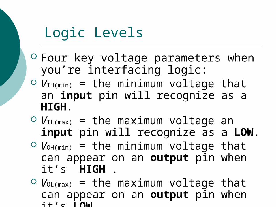
Four key voltage parameters when you’re interfacing logic:
VIH(min) = the minimum voltage that an input pin will recognize as a HIGH.
VIL(max) = the maximum voltage an input pin will recognize as a LOW.
VOH(min) = the minimum voltage that can appear on an output pin when it’s HIGH .
VOL(max) = the maximum voltage that can appear on an output pin when it’s LOW.
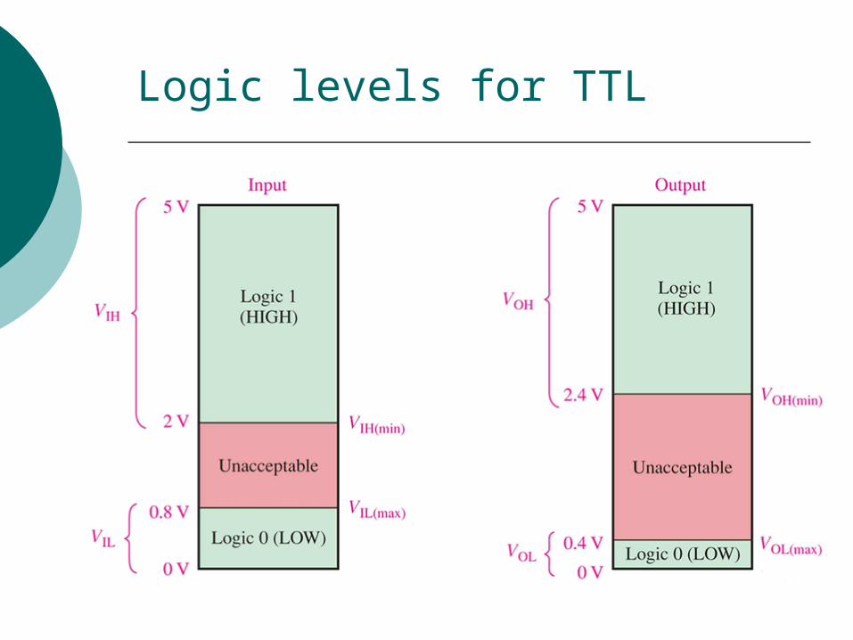
Logic levels for TTL

Noise Margin
The noise margin is the room for error between the voltage that an output pin produces and the voltage that an input pin expects.
VNH = VOH(min) − VIH(min)
VNL = VIL(max) − VOL(max)
Propagation Delay
Data sheets specify propagation delays for low-to-high output transitions (tPLH) and high-to-low output transitions (tPHL).
A device with a smaller propagation delay can run faster (at a higher frequency) than a device with a higher propagation delay.
Next slide shows example waveforms.

Copyright ©2012 by Pearson Education, Inc.All rights reserved.
Digital Electronics: A Practical Approach with VHDL, 9th EditionWilliam Kleitz
Figure 9.10 (Continued) (b) propagation delay times.

Power Dissipation
Recall that power equals current times voltage (P=IV).
So a chip’s power dissipation is given by its supply voltage (VCC) times its supply current (ICC). (Note that we don’t use the voltages and currents on input or output pins.)
A lower-power device wastes less energy, generates less heat, and costs less to run than a higher-power device.

Speed-Power Product
A useful overall measure of a device’s performance is its speed-power product, found by multiplying its average power dissipation times its average propagation delay.
The lower the speed-power product, the better.
Interfacing Logic Families
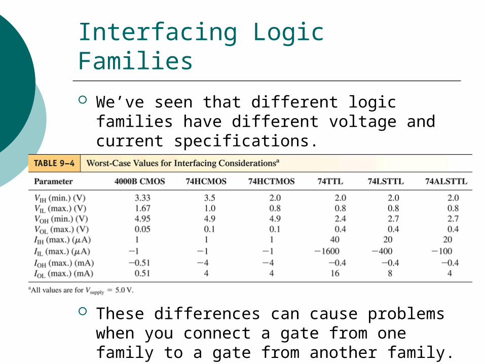
We’ve seen that different logic families have different voltage and current specifications.
These differences can cause problems when you connect a gate from one family to a gate from another family.

Voltage-Related Interfacing Problems
In some interfacing situations, a HIGH output pin may produce a voltage that is too low to be recognized as a HIGH by the input pin it’s connected to.
The solution in such cases is to use a pull-up resistor. See example on next slide.

Interfacing Example: TTL to CMOS
A TTL HIGH output may be as low as 2.4 V. But a CMOS input expects HIGHs to be at
least 3.33 V. Solution: use a pull-up resistor, as shown
in Figure 9-27.

Current-Related Interfacing Problems
In some interfacing situations, either a HIGH output pin may not source enough current to drive the input pin it’s connected to, or a LOW output pin may not sink enough current to drive the input pin it’s connected to.
The solution in such cases is to use a buffer. See example on next slide.

Interfacing Example: CMOS to TTL
A CMOS LOW output can only sink 0.51 mA. But as much as 1.6 mA may flow out of a TTL
LOW input. Solution: use a CMOS buffer, as shown in
Figure 9-29.

1. Make sense of the most important numbers in a datasheet.
2. Understand three kinds of output pins that you’re likely to encounter:
• Totem-pole outputs
• Open-collector outputs
• Three-state outputs
Two Main Goals of Unit 9

Three Kinds of Outputs
TTL chips can have three kinds of outputs: Totem-pole (the most common) Open-collector (discussed in Chapter 9) Three-state (discussed in Chapter 13)
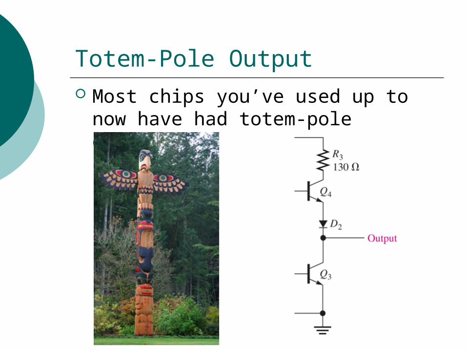
Totem-Pole Output Most chips you’ve used up to now
have had totem-pole outputs.

Copyright ©2009 by Pearson Higher Education, Inc.Upper Saddle River, New Jersey 07458
All rights reserved.
Digital Fundamentals, Tenth EditionThomas L. Floyd
A standard TTL inverter circuit.

Open-Collector Output Missing a transistor internally, so
you must provide an external pull-up resistor.
Two advantages:1. Allows for the use of higher-than-usual
voltages and currents.2. Allows a trick called “wired-AND,”
which means you can AND the outputs of two chips by tying them directly together. (Never tie totem-pole outputs together.)

Copyright ©2009 by Pearson Higher Education, Inc.Upper Saddle River, New Jersey 07458
All rights reserved.
Digital Fundamentals, Tenth EditionThomas L. Floyd
TTL inverter with open-collector output.

Copyright ©2009 by Pearson Higher Education, Inc.Upper Saddle River, New Jersey 07458
All rights reserved.
Digital Fundamentals, Tenth EditionThomas L. Floyd
Open-collector symbol in an inverter.
Some Open-Collector Chips
7405 (Hex Inverters with Open-Collector Outputs)
7409 (Quad 2-Input AND with Open-Collector Outputs)
7412 (Triple 3-Input NAND with Open-Collector Outputs)

Three-State Output (also called tri-state output)
In addition to the two usual output states (HIGH and LOW), has a third output state called high-impedance (“high-Z”).
In the high-Z state, the output is disconnected from the external circuit.
Useful when the outputs of many chips are tied to the same bus: at any time, only one of them should be connected to the bus.

Copyright ©2009 by Pearson Higher Education, Inc.Upper Saddle River, New Jersey 07458
All rights reserved.
Digital Fundamentals, Tenth EditionThomas L. Floyd
The three states of a tristate circuit.

Copyright ©2009 by Pearson Higher Education, Inc.Upper Saddle River, New Jersey 07458
All rights reserved.
Digital Fundamentals, Tenth EditionThomas L. Floyd
Basic tristate inverter circuit.
Some Three-State Chips
74251 (Data Selectors/Multiplexers with 3-State Outputs)
74LS348 (8-Line To 3-Line Priority Encoders With 3-State Outputs)

Copyright ©2009 by Pearson Higher Education, Inc.Upper Saddle River, New Jersey 07458
All rights reserved.
Digital Fundamentals, Tenth EditionThomas L. Floyd
A CMOS inverter circuit.

Three Kinds of CMOS Outputs
Like TTL chips, CMOS chips can have two kinds of special-purpose outputs instead of the usual outputs: Open-drain
Similar to open-collector in TTL Requires an external pull-up resistor
Three-state

• TTL and CMOS are by far the two most common logic families, but you may also encounter chips from other families:• ECL (Emitter-Coupled Logic): The fastest logic
family
• PMOS (p-Channel Metal Oxide Semiconductor)
• NMOS (n-Channel Metal Oxide Semiconductor)
• E2CMOS (Electrically Erasable CMOS)
Other Logic Families
Recommended