Midterm Exam
Solutions

List at least 3 advantages of implementing selected portions of a design in hardware, and at least 3 advantages of implementing the remaining portions of the design in software
Problem 1
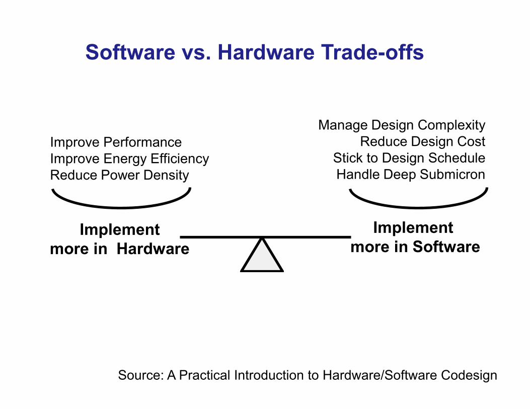
Software vs. Hardware Trade-offs
Implement more in Software
Implementmore in Hardware
Manage Design ComplexityReduce Design Cost
Stick to Design ScheduleHandle Deep Submicron
Improve PerformanceImprove Energy EfficiencyReduce Power Density
Source: A Practical Introduction to Hardware/Software Codesign

Distinct Features of Hardware and Software Design
Hardware Software
Design Paradigm Decomposition in space Decomposition in time
Resource Area (#gates, #Slices) Time (#Cycles)
Flexibility Must be designed in Implicit
Parallelism Implicit Must be designed in
Modeling Model ≠ Implementation Model ≈ Implementation
Reuse Uncommon Common

What are the two primary advantages of Zynq over ASSP?
Problem 2

Comparison with Alternative Solutions
ASIC ASSP 2 Chip Solution
Zynq
Performance ✚ ✚ n ✚
Power ✚ ✚ − ✚
Unit Cost ✚ ✚ − n
Total Cost of Ownership
n ✚ ✚ ✚
Risk − ✚ ✚ ✚
Time to Market − ✚
✚ ✚
Flexibility − − ✚ ✚
Scalability − n ✚ ✚
✚ positive, − negative, n neutral
Source: Xilinx Video Tutorials

Choice Among Various Implementation Platforms
Source: Xcell Journal, no. 88, Q3 2014

List the products of Altera and Microsemi directly competing with Zynq
Problem 3

Alternative Solutions
Xilinx Zynq Zynq-7000 All Programmable SoCs with Cortex-A9 MPCore Altera Arria V & Cyclone V Hard processor system (HPS) with Cortex-A9 MPCore Microsemi Smartfusion2 Cortex M3

List at least 3 industry standards adopted in Vivado
Problem 4

Vivado Design Suite
• 4 years of development and 1 year of beta testing • first version released in Summer 2012 • scalable data model, supporting designs with
up to 100 million ASIC gate equivalents (GEs)
• based on industry standards, such as • AMBA AXI4 interconnect • IP-XACT IP packaging metadata
• Tool Command Language (Tcl) • Synopsys Design Constraints (SDC)

List 3 primary metrics optimized by the Vivado’s Analytical Placer
Problem 5

Multidimensional Analytical Placer
ISE: • One-dimensional, timing-driven place-and-route algorithms
• Simulated annealing algorithms that determine randomly where the tool should place logic cells
• Does adequate job for FPGAs below 1 million GEs
Vivado: • Modern multidimensional analytic placement algorithm
• Deterministically finds a solution that primarily minimizes: timing, congestion, and wire length
• Better results, fewer iterations • Efficient up to 100 million GEs

Vivado’s Multidimensional Optimization
Source: Xcell, no. 79, 2012

Explain the meaning of the dashed rectangles in the block diagram of the GPIO core shown below
Problem 6

Source: LogiCORE IP AXI GPIO: Product Specification
AXI GPIO Resource Utilization and Maximum Clock Frequency

Explain the effect of unmarking the Enable Interrupt option in the Vivado GUI window shown below on the block diagram of AXI GPIO shown next
Problem 7

Block Diagram of AXI GPIO
IPIC – IP Interconnect interface
enabled only when the C_INTERRUPT_PRESENT generic set to 1
Source: LogiCORE IP AXI GPIO: Product Specification

Source: LogiCORE IP AXI GPIO: Product Specification
GPIO Core Parameters

How many different types of interrupts can be generated by the AXI GPIO configured as shown in Question 7?
Problem 8

Source: LogiCORE IP AXI GPIO: Product Specification
Interrupt Enable Registers, IP IER

Which of the following PS-PL interfaces is used for communication between the ARM processors
and AXI GPIOs in Zynq?
Problem 9
a. S_AXI_GP b. M_AXI_GP c. S_AXI_ACP, or d. S_AXI_HP?

AXI Interconnects and Interfaces
Source: The Zynq Book

List at least 3 possible uses of the Generate Mode of AXI Timer
Problem 10

Generate Mode • Counter when enabled begins to count up or down • On transition of carry out, the counter
• stops, or • automatically reloads the initial value from the load register,
and continues counting • if enabled, GenerateOut is driven to 1 for one clock cycle • if enabled, the interrupt signal for the timer is driven to 1
• Can be used to • Generate repetitive interrupts • One-time pulses • Periodical signals

Block Diagram of AXI Timer
Source: LogiCORE IP AXI Timer: Product Guide

2. Output compare - generating signals with the given timing characteristics
pulse width
single pulse periodical signal
period
Functions of a Typical Timer (2)
List two distinct parts of any Hardware Platform Specification
Problem 11

Hardware Platform Specification (1)

Hardware Platform Specification (2)

Hardware Platform Specification (3)

Which company developed AMBA and AXI?
Problem 12

Source: M.S. Sadri, Zynq Training
Solution Adopted in ZYNQ
Advanced Microcontroller Bus Architecture (AMBA): an open-standard, on-chip interconnect specification for the connection and management of functional blocks in system-on-a-chip (SoC) designs. First version introduced by ARM in 1996. AMBA Advanced eXtensible Interface 4 (AXI4): the fourth generation of AMBA interface defined in the AMBA 4 specification, targeted at high performance, high clock frequency systems. Introduced by ARM in 2010.

List at least 3 functions of AXI Interconnect
Problem 13

Source: M.S. Sadri, Zynq Training
Addressing of Slaves

Source: M.S. Sadri, Zynq Training
AXI Interconnect Address Decoding

Source: M.S. Sadri, Zynq Training
Clock Domain and Width Conversion

Source: M.S. Sadri, Zynq Training
Hierarchical AXI Interconnects

List at least 4 ports of an AXI-Stream Master (other than clk and reset),
and divide them into inputs and outputs
Problem 14

Source: M.S. Sadri, Zynq Training
Selected AXI Stream Ports
Name the system-on-chip bus standard recommended for use by opencores.org
Problem 15

Bus Developed by
High-Performance Shared Bus
Peripheral Shared
Bus
Point-to-Point Bus
AMBA v3 ARM AHB APB AMBA v4 ARM AXI4 AXI4-Lite AXI4-Stream
Coreconnect IBM PLB OPB Wishbone SiliCore
Corp. Crossbar Topology
Shared Topology
Point to Point Topology
Avalon Altera Avalon-MM Avalon-MM Avalon-ST AMBA: Advanced Microcontroller Bus Architecture AXI: Advanced eXtensible Interface AHB: AMBA High-speed Bus APB: AMBA Peripheral Bus PLB: Processor Local Bus OPB: On-chip Peripheral Bus MM: Memory Mapped ST: Streaming
Competing System-on-Chip Bus Standards
Source: A Practical Introduction to Hardware/Software Codesign

List at least 6 ports of an AXI-Full Slave (other than clk and reset),
and divide them into inputs and outputs
Problem 16

AXI4 Interface Write Address Channel
Write Data Channel
Write Response Channel
Read Address Channel
Read Data Channel
Source: The Zynq Book

Source: ARM AMBA AXI Protocol v1.0: Specification
Write Burst

Read Burst

port ( -- Users to add ports here LEDs_out : out std_logic_vector(3 downto 0);
-- User ports ends -- Do not modify the ports beyond this line
-- Global Clock Signal S_AXI_ACLK : in std_logic; -- Global Reset Signal. This Signal is Active LOW S_AXI_ARESETN: in std_logic; -- Write address (issued by master, acceped by Slave) S_AXI_AWADDR: in std_logic_vector(C_S_AXI_ADDR_WIDTH-1 downto 0);
. . . . . . . .
Entity Declaration (2)

. . . . . . . . -- Read address valid. This signal indicates that the channel
-- is signaling valid read address and control information. S_AXI_ARVALID : in std_logic; -- Read address ready. This signal indicates that the slave is
-- ready to accept an address and associated control signals. S_AXI_ARREADY : out std_logic; -- Read data (issued by slave) S_AXI_RDATA : out std_logic_vector(C_S_AXI_DATA_WIDTH-1 downto 0); -- Read response. This signal indicates the status of the
-- read transfer. S_AXI_RRESP : out std_logic_vector(1 downto 0); -- Read valid. This signal indicates that the channel is
-- signaling the required read data. S_AXI_RVALID : out std_logic; -- Read ready. This signal indicates that the master can
-- accept the read data and response information. S_AXI_RREADY : in std_logic );
end led_controller_v1_0_S00_AXI;
Entity Declaration (3)

Explain the need for the volatile keyword in the following definition of Xil_In32():
Problem 17
u32 Xil_In32(u32 Addr) { return *(volatile u32 *) Addr; }

Which of the following operations (if any) can be omitted in case of the DMA-based communication between an ARM core and a hardware accelerator using ACP? Write to Accelerator
• processor allocates buffer • processor writes data into buffer • processor flushes cache for buffer • processor initiates DMA transfer
Read from Accelerator
• processor allocates buffer • processor initiates DMA transfer • processor waits for DMA to complete • processor invalidates cache for buffer • processor reads data from buffer
Problem 18

Coherent AXI DMA-based Accelerator Communication
Write to Accelerator • processor allocates buffer • processor writes data into buffer • processor flushes cache for buffer • processor initiates DMA transfer
Read from Accelerator • processor allocates buffer • processor initiates DMA transfer • processor waits for DMA to complete • processor invalidates cache for buffer • processor reads data from buffer

What operation starts a Simple DMA Transfer when using AXI DMA?
Problem 19

1. Start the MM2S channel running by setting the run/stop bit
to 1, MM2S_DMACR.RS = 1.
2. If desired, enable interrupts by writing a 1 to
MM2S_DMACR.IOC_IrqEn and MM2S_DMACR.Err_IrqEn.
3. Write a valid source address to the MM2S_SA register.
4. Write the number of bytes to transfer in
the MM2S_LENGTH register.
The MM2S_LENGTH register must be written last.
All other MM2S registers can be written in any order.
Simple DMA Transfer Programming Sequence for MM2S channel (1)

Explain the primary difference between Simple DMA transfer
and Scatter-Gather DMA Transfer
Problem 20

Scatter Gather DMA Mode
Source: Symbian OS Internals/13. Peripheral Support

Chain of Buffer Descriptors (BDs)

Which core can be used to simplify the development of an AXI-Full Master?
Problem 21

Source: M.S. Sadri, Zynq Training
Ways of Implementing AXI4 Master Units

Explain the primary difference between DMA and Central DMA
Problem 22

Source: Xilinx Advanced Embedded System Design on Zynq
• High-bandwidth Direct Memory Access (DMA) between a memory-mapped source address and a memory-mapped destination address
• Optional Scatter Gather (SG)
• Initialization, status, and control registers are accessed through an AXI4-Lite slave interface
Central DMA

Explain the primary difference between an Integrated Logic Analyzer (ILA) and
Virtual Input Output (VIO)
Problem 23

Integrated Logic Analyzer
Source: Integrated Logic Analyzer v5.0, LogiCORE IP Product Guide

Virtual Input Output
Source: LogiCORE IP Virtual Input/Output

Estimate the minimum amount of memory required by ILA configured as shown below
Problem 24

List at least 3 different ways of dealing with the most time-critical
C functions identified by the profiler
Problem 25

Determine the software "critical path" by profiling – Profiling measures where the CPU is spending its cycles on a function-by-
function or task-by-task basis – Similar to timing analysis in hardware – Informs the system designer which software routine may be a candidate to
hardware-accelerate
Functions can be rewritten to improve efficiency in a number of ways – Implementation in assembly code rather than C – Writing faster C code, for example limit pointer use
Profiling and Performance 18-66
Hardware and Software Partitioning
© Copyright 2014 Xilinx
Recommended