
September 2013 Page 1
Dynamic Transformer Rating Model Guidelines
Introduction This document describes how to set up, configure and run the Dynamic Transformer Rating model in
Ipsa. The Dynamic Transformer Rating model (DTR) has been developed for the WPD FALCON
project by Aston University. It models the thermal time constants of a transformer to determine
when the transformer oil temperature exceeds the maximum allowable hot spot oil temperature.
The model also estimates the insulation degradation due to oil temperature effects and optionally
determines the remaining transformer life.
The DTR model is provided in the form of an Ipsa Plugin model. It can be added to any transformer
in the network by following the instructions in the section below. A test network is provided as well
as a Python script to assist in the set up of the model.
This guide contains the following sections;
1. Data Requirements
2. Add DTR Model to Ipsa
3. Add Extended Data to Network Model
4. Add DTR Model to Transformer
5. DTR Simulations

Dynamic Transformer Rating Model Guide
August 2013 Page 2
1. Data Requirements
The DTR data is split into the basic mechanical transformer data and the data required for the
thermal model. The basic mechanical data is added to the transformer as extended data whilst the
thermal model data is entered as part of the plugin model. The following tables provide a summary
of the input data requirements together with the default values. All data should be entered into
Ipsa without units.
Note that all busbars in the model should have a nominal voltage assigned to them, thereby allowing
Ipsa to calculate the transformer currents.
Table 1 - DTR Data Parameters
Parameter Default Values
Description
Ambient_Temp 20°C Ambient air temperature for the transformer. May be different depending on location, e.g. indoor/outdoor
Cooling ONAN, ONAF or OFAF
Cooling classification which determines the thermal time constants. Defaults to OFAF if the type is not recognised.
HV_Rated_kV 33kV HV nominal voltage in kV
Rated_kVA 24000kVA Nominal rated transformer power in kVA
No_Load_Loss_kW 50kW No load losses in kW
Load_Loss_kW 100kW Load losses in kW
Core_Oil_Weight 230kg Total weight of the transformer core and oil in kg
Tank_Weight 415kg Total weight of the transformer tank and fittings (excluding the core and oil) in kg
Oil_Volume 272l Oil volume in litres
Ambient_Temp 20°C Ambient air temperature for the transformer. May be different depending on location, e.g. indoor/outdoor
Cooling ONAN, ONAF or OFAF
Cooling classification which determines the thermal time constants. Defaults to OFAF if the type is not recognised.
Maximum Temperature
120°C Maximum allowed temperature of the transformer hot spot in degrees C. An overload is reported if the hot spot temperature rises above this value for longer than the specified time limit
Max Time at Max Temperature
1 hr The maximum time, in hours, for which the transformer hot spot temperature can be above the Maximum Temperature limit without resulting in an overload.
Loss of Life Limit 4% per annum
The maximum loss of life allowed per day in percent of the total life. If the calculated loss of life per day is greater than this value then an overload is reported.
Normal Insulation Life
25 years The normal design life of the transformer in years.
Dynamic Transformer Rating Model Guide
August 2013 Page 3
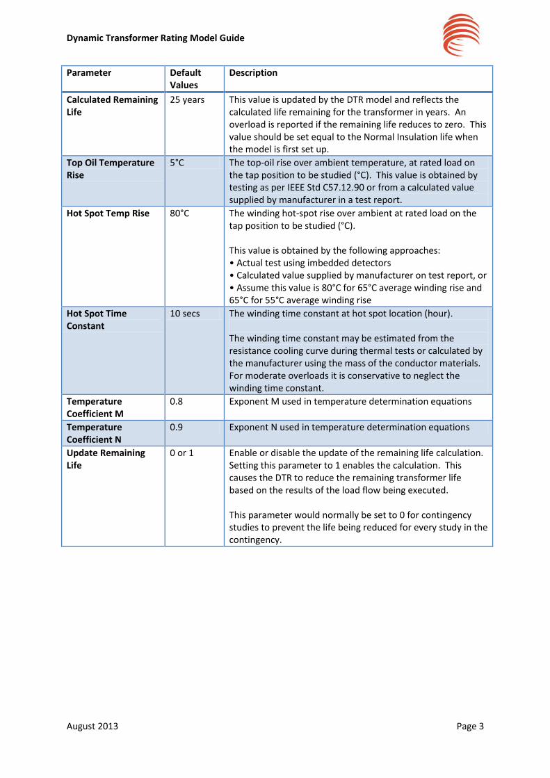
Parameter Default Values
Description
Calculated Remaining Life
25 years This value is updated by the DTR model and reflects the calculated life remaining for the transformer in years. An overload is reported if the remaining life reduces to zero. This value should be set equal to the Normal Insulation life when the model is first set up.
Top Oil Temperature Rise
5°C The top-oil rise over ambient temperature, at rated load on the tap position to be studied (°C). This value is obtained by testing as per IEEE Std C57.12.90 or from a calculated value supplied by manufacturer in a test report.
Hot Spot Temp Rise 80°C The winding hot-spot rise over ambient at rated load on the tap position to be studied (°C). This value is obtained by the following approaches: • Actual test using imbedded detectors • Calculated value supplied by manufacturer on test report, or • Assume this value is 80°C for 65°C average winding rise and 65°C for 55°C average winding rise
Hot Spot Time Constant
10 secs The winding time constant at hot spot location (hour). The winding time constant may be estimated from the resistance cooling curve during thermal tests or calculated by the manufacturer using the mass of the conductor materials. For moderate overloads it is conservative to neglect the winding time constant.
Temperature Coefficient M
0.8 Exponent M used in temperature determination equations
Temperature Coefficient N
0.9 Exponent N used in temperature determination equations
Update Remaining Life
0 or 1 Enable or disable the update of the remaining life calculation. Setting this parameter to 1 enables the calculation. This causes the DTR to reduce the remaining transformer life based on the results of the load flow being executed. This parameter would normally be set to 0 for contingency studies to prevent the life being reduced for every study in the contingency.

Dynamic Transformer Rating Model Guide
August 2013 Page 4
2. Add DTR Model to Ipsa
2.1. The DTR model is provided in the form of a DLL file and is normally supplied as part
of the Ipsa install.
2.2. Confirm that there is a file called ‘IDynRatingTest.dll’ in the Ipsa plugins
directory “C:\Program Files\IpsaPower\Ipsa 2.3\plugins”, as
shown below;

Dynamic Transformer Rating Model Guide
August 2013 Page 5
2.3. The DTR model will be checked when Ipsa is launched and the user can check it has
been correctly loaded by starting Ipsa and viewing the Progress window. The
following message will be displayed if the model is present;
2.4. If the above message is not displayed then please contact [email protected]
for further assistance.

Dynamic Transformer Rating Model Guide
August 2013 Page 6
3. Add Extended Data to Network Model
Some of the transformer data is set using Ipsa Extended Data fields. For convenience a Python
script has been provided which configures the required Extended Data fields automatically.
Perform the following steps to add the required data fields to each Ipsa network;
3.1. Open the Ipsa network containing the transformers to which the DTR model is to be
applied
3.2. Go to the Analysis menu and select the Run Script… item
3.3. Navigate to the ConfigureDTR.py script. Normally this will be in the Ipsa script
directory should below. If the script has been emailed or downloaded from the
website then navigate to the folder where it was saved into.
“C:\Program Files\IpsaPower\Ipsa 2.3\scripts”
3.4. Select the script and click Open. The script will prompt you as required and issue
warnings if not successful. Please contact [email protected] if errors are
encountered.

Dynamic Transformer Rating Model Guide
August 2013 Page 7
4. Add DTR Model to Transformer 4.1. Open the network model in Ipsa and locate the transformer which is to have the DTR
model added to it.
4.2. Display the Transformer properties dialog shown below by either;
Double clicking the transformer on the diagram
Double click the item in the stack bar
4.3. Select the ‘Transient, harmonics, IEC 60909 and Reliability’ tab
4.4. Select the Plug-in option in the Controller Model section

Dynamic Transformer Rating Model Guide
August 2013 Page 8
4.5. Select the ‘FALCON Transformer DAR’ from the selection box. The dialog will now
display the selected plug-in name and an Edit button as shown below;
4.6. Click the Edit button and the DTR Properties dialog will be displayed as shown below.
This dialog contains the thermal properties for the transformer;

Dynamic Transformer Rating Model Guide
August 2013 Page 9
4.7. The parameters can be edited as required for each transformer.
The Restore Defaults button can be used to return to the default parameters
as shown above.
4.8. Click OK to save the data and return to the Transformer dialog
4.9. The remaining mechanical transformer data is set in the transformer extended data
fields.
4.10. Click the Extended Data tab in the transformer dialog to view the mechanical
transformer properties, as shown below;
4.11. The mechanical transformer data can now be entered in the corresponding fields.
Enter either ONAN, ONAF or OFAF only for the cooling type
All other data should be entered as a number only, i.e. without units
4.12. Click OK to save the data for the transformer
4.13. The DTR model is now ready for use

Dynamic Transformer Rating Model Guide
August 2013 Page 10
5. DTR Simulations
The DTR model is intended for use with Ipsa load profiles to allow a time series representation of the
network load changes. The model will run automatically during any Profile studies, it will not run
during normal load flow studies.
No further set up is required in order to run the model. For this version of the model all output data
is printed in the Ipsa Progress window.
A test network has been provided which can be used to ensure that the model operates correctly.
This network contains a transformer with a DTR model and a load profile. Follow the steps below to
run the model and reproduce the test case results;
5.1. Open Ipsa and open the ‘Profile Test’ network supplied with the DTR model
5.2. This contains a 24MVA 33/11kV transformer with a DTR model, the model properties
are shown below;

Dynamic Transformer Rating Model Guide
August 2013 Page 11
5.3. The model also contains a single 415V load with a profile as shown below. This
profile contains 48 values representing one day of half hourly demand data.

Dynamic Transformer Rating Model Guide
August 2013 Page 12
5.4. Click on the Analysis menu and select the ‘Run Profile’ option. This runs all the load
flow calculations for the profile associated with the load. The results are presented
in the Progress window as shown below;
[Sep 30 13 14:53:29] Starting profile analysis [Sep 30 13 14:53:29] Plugin item FALCON Transformer DAR controlling 33kV Busbar.11kV Busbar.Transformer connected to plugin (FALCON Transformer DAR) instance [1] [Sep 30 13 14:53:29] Plugin: loaded model (FALCON Transformer DAR): FALCON Transformer DAR controlling 33kV Busbar.11kV Busbar.Transformer [Sep 30 13 14:53:29] Plugin FALCON Transformer DAR [1]: Transformer extended data DAR parameters ok [Sep 30 13 14:53:29] Plugin FALCON Transformer DAR [1]: Transformer hot spot temperature = 100C, elapsed time = 0 hours [Sep 30 13 14:53:29] Plugin FALCON Transformer DAR [1]: Remaining life = 25 years [Sep 30 13 14:53:29] Plugin FALCON Transformer DAR [1]: Transformer hot spot temperature = 97.3172C, elapsed time = 0.5 hours [Sep 30 13 14:53:29] Plugin FALCON Transformer DAR [1]: Remaining life = 24.9985 years [Sep 30 13 14:53:29] Plugin FALCON Transformer DAR [1]: Transformer hot spot temperature = 73.6902C, elapsed time = 1 hours [Sep 30 13 14:53:29] Plugin FALCON Transformer DAR [1]: Remaining life = 24.9977 years [Sep 30 13 14:53:29] Plugin FALCON Transformer DAR [1]: Transformer hot spot temperature = 97.3317C, elapsed time = 1.5 hours [Sep 30 13 14:53:29] Plugin FALCON Transformer DAR [1]: Remaining life = 24.9967 years … [Sep 30 13 14:53:29] Plugin FALCON Transformer DAR [1]: Transformer hot spot temperature = 107.288C, elapsed time = 22.5 hours [Sep 30 13 14:53:29] Plugin FALCON Transformer DAR [1]: Remaining life = 24.9109 years [Sep 30 13 14:53:29] Plugin FALCON Transformer DAR [1]: Transformer exceeded daily loss of life limit. Daily loss = 0.0204275%, limit = 0.0109589%/day [Sep 30 13 14:53:29] Plugin FALCON Transformer DAR [1]: Transformer hot spot temperature = 102.505C, elapsed time = 23 hours [Sep 30 13 14:53:29] Plugin FALCON Transformer DAR [1]: Remaining life = 24.9058 years [Sep 30 13 14:53:29] Plugin FALCON Transformer DAR [1]: Transformer exceeded daily loss of life limit. Daily loss = 0.0202105%, limit = 0.0109589%/day [Sep 30 13 14:53:29] Plugin FALCON Transformer DAR [1]: Transformer hot spot temperature = 95.4207C, elapsed time = 23.5 hours [Sep 30 13 14:53:29] Plugin FALCON Transformer DAR [1]: Remaining life = 24.9009 years [Sep 30 13 14:53:29] Plugin FALCON Transformer DAR [1]: Transformer exceeded daily loss of life limit. Daily loss = 0.0198836%, limit = 0.0109589%/day [Sep 30 13 14:53:29] Plugin FALCON Transformer DAR [1]: Transformer hot spot temperature = 89.4536C, elapsed time = 24 hours [Sep 30 13 14:53:29] Plugin FALCON Transformer DAR [1]: Remaining life = 24.896 years [Sep 30 13 14:53:29] Plugin FALCON Transformer DAR [1]: Transformer exceeded daily loss of life limit. Daily loss = 0.0195211%, limit = 0.0109589%/day [Sep 30 13 14:53:29] 48 profile categories run.
Recommended


![Digital Asset Management - Overload Capacity of Power ......2.1 Recommended thermal characteristics for exponential equations, [6] . . . . . . .13 2.2 Transformer dynamic thermal rating](https://img.dokumen.tips/doc/110x75/612183b59acd5b0a49086c69/digital-asset-management-overload-capacity-of-power-21-recommended-thermal.jpg)