DOE – An Effective Tool for Experimental Research
Dr. R. Sudhakaran
Prof & Head
Department of Mechanical Engineering
SNS College of Engineering, Coimbatore
1

Introduction• Experiment
– Systematic procedure carried out under controlled conditions to determine an known/unknown effect, to test or establish a hypothesis
– Used to evaluate the impact of process inputs on the process outputs
– Determine the target level of inputs to achieve a desired result
• Design of Experiments– DOE is a formal mathematical method for
systematically planning and conducting scientific studies that change experimental variables together in order to determine their effect of a given response.
2

DOE - Terminologies• Factors
• Levels
• Response
3

Designed experiments - Uses
– Comparing Alternatives – In cake baking, comparing results from two different types of flour
– Identifying the significant inputs affecting an output– Achieving an optimal process output – How to get
exact taste and consistency in Chocolate cake– Targeting an output – How to make a cake as moist
as possible without disintegrating– Improving process or product robustness – Can the
factors and levels be modified – Cake will come out neatly the same
– Balancing tradeoffs – Multiple critical quality characteristics that require optimization – “ How to produce best quality cake with simplest recipe and short baking time
4

• The Design of an experiment addresses the questions outlined by stipulating the following:
• The factors to be tested.
• The levels of those factors.
• The structure and layout of experimental runs, or conditions.
• A well-designed experiment is as simple as possible - obtaining the required information in a cost effective and reproducible manner.
5

BASIC STEPS IN DOE
• Four elements associated with DOE: – The design of the experiment, – The collection of the data, – The statistical analysis of the data, and– The conclusions reached and
recommendations made as a result of the experiment.
6

7

PLANNING A DOE• Everyone involved in the experiment should have a clear
idea in advance of exactly – What is to be studied?– The objectives of the experiment– The questions one hopes to answer and– The results anticipated
• Select a response/dependent variable (variables) that will provide information about the problem under study.
• Select a proposed measurement method for this response variable, including an understanding of the measurement system variability.
8

PLANNING A DOE• Select the independent variables (factors), the number of
levels for each factor and the levels of each factor.
• Choose an appropriate experimental design that will allow your experimental questions to be answered once the data is collected and analyzed.
• Perform the experiment (collect data) paying particular attention to measurement system accuracy, while maintaining as uniform an experimental environment as possible.
9

PLANNING A DOE
• Analyze the data using the appropriate regression model insuring that attention is paid to checking the model accuracy.
• Based on the results of the analysis, – draw conclusions/inferences about the results, – interpret the physical meaning of these results,– determine the practical significance of the findings,
and make recommendations for a course of action
10

Case Study - Amplifier• Objective- To investigate sensitivity of the
amplifier due to process variation
• Factors– Width of the micro strip lines (W)– Resistor (R)– Capacitor (c)
• Response– Gain of the amplifier (G)
11

12
Choose three variables with their +1 and -1 :Choose three variables with their +1 and -1 :
Width of lines (W) W=W_nominal ± .5 um Width of lines (W) W=W_nominal ± .5 um
Resistors (R) R = R_nominal ± 5% Resistors (R) R = R_nominal ± 5%
Capacitors (C) C = C_nominal ± 5% Capacitors (C) C = C_nominal ± 5%

Process variables and their levels for Experiments
13
Parameter Units Factor levels-1 0 +1
Width of the Micro strip μm
9.5 10 10.5
Resistor Ohms 19 20 21
Capacitor Milli Farad
500 1000 1500

• The experiments are conducted eight times to get the gain for all the combination of +1’s and -1’s of the three elements
14
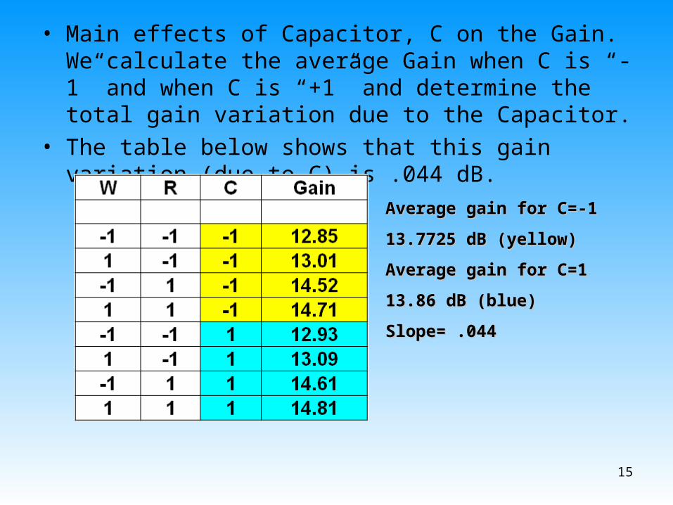
• Main effects of Capacitor, C on the Gain. We calculate the average Gain when C is “-1” and when C is “+1” and determine the total gain variation due to the Capacitor.
• The table below shows that this gain variation (due to C) is .044 dB.
15
Average gain for C=-1Average gain for C=-1
13.7725 dB (yellow) 13.7725 dB (yellow)
Average gain for C=1Average gain for C=1
13.86 dB (blue) 13.86 dB (blue)
Slope= .044 Slope= .044

• The gain variation due to the Resistor is .85 dB, which is much higher than that of the Capacitor.
16
Average gain for R=-1Average gain for R=-1
12.97 dB (blue) 12.97 dB (blue)
Average gain for R=1Average gain for R=1
14.6625 dB (green) 14.6625 dB (green)
Slope = .85 Slope = .85
• This tells us that the resistor is a trouble This tells us that the resistor is a trouble component and causes higher variation in component and causes higher variation in the gain. the gain.

Plotting Main Effects of C and R
17

• DOE is also very useful in getting information on the interactions between the elements in a design and how these interactions affect the variation in the output
18
Average gain for W*R=-1Average gain for W*R=-1
13.8075 dB (blue) 13.8075 dB (blue)
Average gain for W*R=1Average gain for W*R=1
13.825 dB (pink) 13.825 dB (pink)
Slope = .0088 Slope = .0088

19

• Doing the same procedure for all elements and their interactions, we obtain the following results
• Obtaining the Rest of the Coefficients
20

21

22

Plan of WorkIdentifying the process variablesIdentifying the process variables
Developing the design matrixDeveloping the design matrix
Conducting the experiments as per the design matrixConducting the experiments as per the design matrix
Development of mathematical modelsDevelopment of mathematical models
Evaluation of coefficients of the modelsEvaluation of coefficients of the models
Checking adequacy of the modelsChecking adequacy of the models
Testing the regression coefficients of the modelsTesting the regression coefficients of the models
Validation of the mathematical modelsValidation of the mathematical models
Analyzing the Analyzing the results results

Limits of Process Variables
• The angular distortion is a function of many independently controllable process parameters such as welding current (I), welding speed (V), gas flow rate (Q), gun angle (θ), plate length (L)
• The design plan was decided based on the practical considerations for the system
Factor Upper limit
Lower limit
Welding current (I)
amps
110 70
Welding speed (V)
mm/min
120 80
Gas flow rate (Q) liter/min
25 5
Gun Angle (θ)
Degrees
90 50
Plate Length (L) mm
200 100

Limits of Process VariablesProcess
parametersLimits
-2 -1 0 +1 +2
Welding current amps
70 80 90 100 110
Welding Speed mm/min
80 90 100
110 120
Gas flow rateLiter/min
5 10 15 20 25
Gun angle Degrees
50 60 70 80 90
Plate Length mm
100 125 150 175 200

Design Matrix
The design matrix chosen to conduct the experiments was five factor, five levels central composite rotatable designs consisting of 32 sets of coded conditions .
This design matrix comprises a full replication factorial design i.e. 24 = 16 factorial design plus 7 center points and 8 star points.

Evaluation of Regression Coefficients
The response function can be expressed as α =f (θ, V, L, I, Q) and the relationship selected is a second order response surface.
The function is as follows

• Quality America – DOE PC –IV software was used to calculate the coefficients.

Development of Mathematical Model
• Insignificant coefficients were dropped along with the parameters with which they are associated.
• This was carried out by conducting backward elimination analysis with t- probability criterion kept at 0.75
• The final mathematical model is as follows

30

31

Thank You
32
Recommended