CECW-EG
Engineer Regulation
1110-2-1925
Department of the ArmyU.S. Army Corps of Engineers
Washington, DC 20314-1000
ER 1110-2-1925
3 July 1969
Engineering and Design
FIELD CONTROL DATA FOR EARTH ANDROCKFILL DAMS
Distribution Restriction StatementApproved for public release; distribution is unlimited.
—Basic Reprint with change 1 & 2 Included.
THIS CONSTITUTES CHANGE 2 ~ ER 1110-2-1925, 3 JULY 1969This change entirely supersedes Change 1, 14 April 1970
ENGCW-ES
RegulationNo. 1110-2-1925
DEPARTMENT OF Ti-lEARMY ER 1110-2-1925Office of the Chief of Engineers Change 2
Washington, D.C. 20314 20 August 1971
3 July 1969
ENGINEERING AND DESIGNField Control Data for Earth and Rockfill Dams
(RCS ENGCW-E-11 (RI))
* :;d:=”This regulation prescribes responsibilities and pro-
or reporting field control data for earth and rockfill dams. *
2. Applicability. The reporting procedure described herein appliesto all divisions and districts engaged in the construction of earth androckfill dams.
* 3“ u“ As required by EN 1110-2-2300, Earth and Rock-Fill Dams -General Design and Construction Considerations, a complete constructionrecord of a dam will be kept for use in construction, operation, andmaintenance of the project. These records provide useful data fordesigning alterations and additions to the structure or aiding indetermining causes of operating difficulties. Included in these recordsare data on methods of compaction, in-place unit weight and moisturecontent, piezometers, surface monuments, and slope indicators. *
* 4. Procedure for Reporting. During construction of the dam, all controldata will be summarized at the end of each month on the ENG Forms shownin Appendix I. Since these forms may be used to tabulate the daily fieldcontrol data, it is necessary only to reproduce a copy to forward tothe District. Data on ENG Forms 4287, 4287A, 4287B and on ENG Forms 4076,4077, 4078, 4079, 4080, and 4081 will be forwarded by the District toDivision offices.
., *
This regulation rescinds ER 1110-2-192S dated 31 July 1967
1
ER 1110-2-19253 July 1%9
.-
5. Use of Forms. me ENG fo~ in lippendixI were developed afteran analysis of the v-ious field control data forms in use throughoutthe Corps. Instructions for completing the forms are outlined at thebottom of each form; supplementary instructions are given in Appendix11. While these forms are designed to permit recording of appropriatedata for any type of dam, there may be satiations where it is notnecessary to use all columns. To prevent duplication, use of localforms in lieu of these standard ones should be discouraged, unlessspecial circumstances indi:ate that local fores are more appropriate.However, the division or di~trict may require additional presentationssuch as gradation curves or graphical summaries of the in-situembanbnt water content as related to optimum water content. Theinformation outlined in Appendix 111 should be submitted with t~einitial report or whenever changes ,ari?made,
FOR THE CmEF OF ENGIMEN:
Q+Y&e
PHILIP . BOERGER ‘Colonel, Corps of EngineersExecutive
3 AppendicesApp I Reporte FormsApp 11 Supp Inst~uctions
for Report ForesApp III Data to be Furnished
wit”hInitial R,eport
2.- -’

ER 111O-2-19253 July 1969
Appendix I
Report Forms for Field Control Data forEarth and Rockfill Dams
The following forms are to be used in reporting field control datato the U.S. Army Engineer Waterways Experiment Station:
1. Summary of Field Compaction Control of Impervious or SemiperviousSoils for Civil Works Projects (ENG FORM 4080)
2. Summary of Field Compaction Control of Pervious Soils and Rockfj.11for Civil Works Projects (ENG FORM 4081)
Closed-System Piezometer Data for Civil Works Projects (ENG FORM4076)3”
4* Open-System Piezometer Data for Civil Works Projects (ENG FORM4077)
Subsurface Settlement Plate Data for Civil Works Projects(ENG~;RM 4078)
Surface Reference Point Data for Earth and Rockfill Dams(ENG~6RM 4079)
7. Periodic S~ary of Field Compaction Control Data (ENG FORMS4287, 4287A, 4287B)
ER 1110-2-19253 July 1969
Appendix 11
Supplementary Instructions for Report Forms
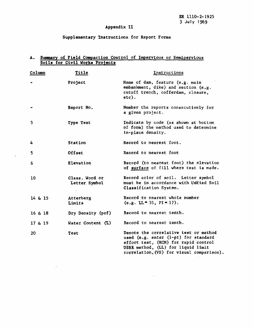
A. S~ry of Field ComPaction Control of Impervious or SemiPerviousSoils for Civil Works Projects
column Title
.
4
5
6
10
14 & 15
16 & 18
17 & 19
20
Project
Report No.
Type Test
Station
Offset
Elevation
Class. Word orLetter Symbol
AtterbergLimits
Dry Density (pcf)
Water Content (%)
Test
Instructions
Name of dam, feature (e.g. mainembantient, dike) and section (e.g.cutoff trench, cofferdam, closure,etc).
Number the reports consecutively fora given project.
Indicate by code (as shown at bottomof form) the method used to determinein-place density.
Record to nearest foot.
Record to nearest foot
Record (to nearest foot) the elevationof surface of fill where test is made.
Record color of soil. Letter symbolmust be in accordance with Udfied SoilClassification System.
Record to nearest whole number(e.g. LL=35, PI=17).
Record to nearest tenth.
Record to nearest tenth.
Denote the correlative test or methodused (e.g. enter (1-pt) for standardeffort test, (RCM) for rapid controlUSBR method, (LL) for liquid limitcorrelation, for visual comparison).
ER 1110-2-19253 July 1969App II
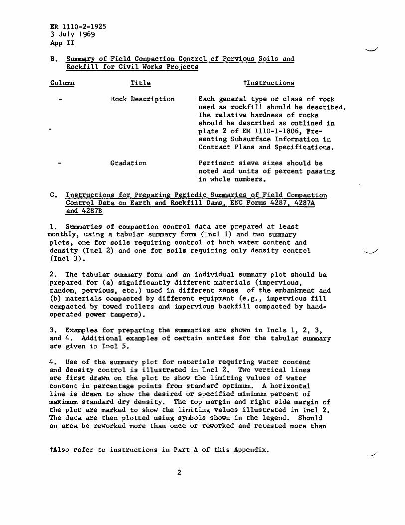
B. Surmnaryof Field Compaction Control of Pervious Soils andRockfill for Civil Works Projects
Coil.mln Title tInstructions
Rock Description Each general type or classused as rockfill should be
of rockdescribed.
The relative hardness of rocksshould be described as outlined inplate 2 of EM 1110-1-1806, Pre-senting Subsurface Information inContract Plans and Specifications.
Gradation Pertinent sieve sizes should benoted and units of percent passingin whole numbers.
c. Instructions for Preparing Periodic Smaries of Field CompactionControl Data on Earth and Rockfill Dams, ENG Forms 4287, 4287Aand 4287B
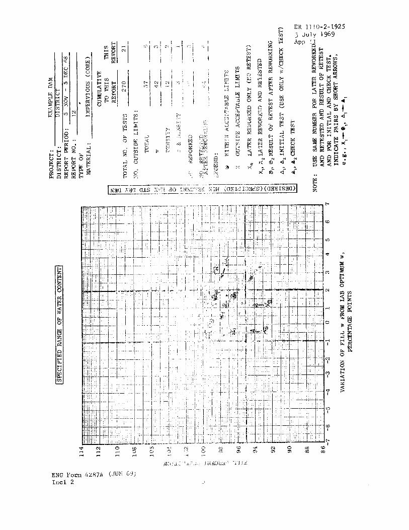
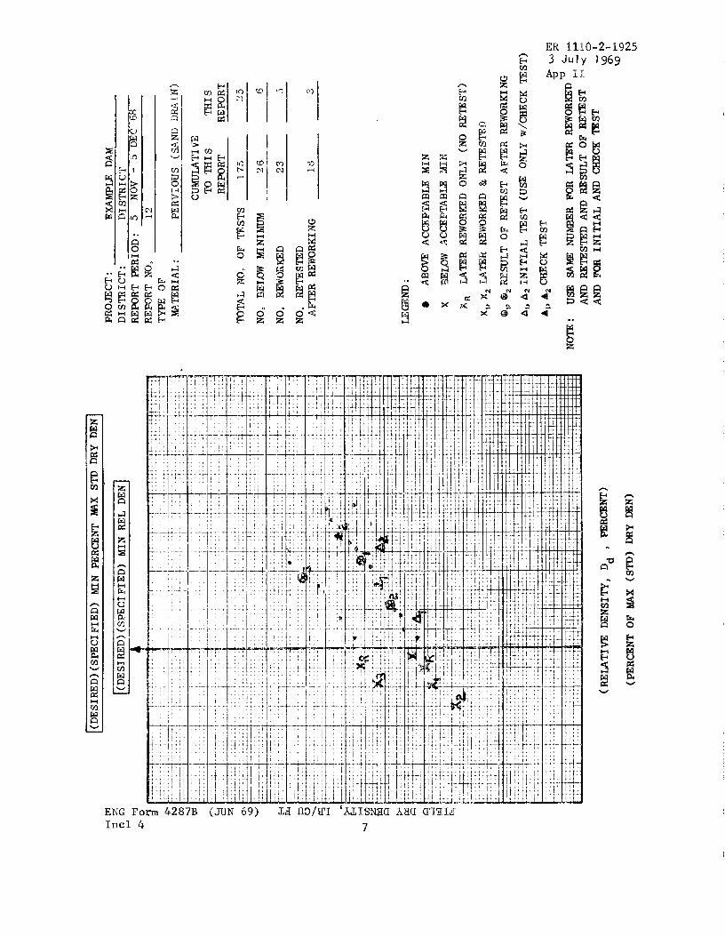
1. S~aries of compaction control data are prepared at leastmonthly, using a tabular smary form (Incl 1) and two s~aryplots, one for soils requiring control of both water content anddensity (Incl 2) and one for soils requiring only density control(Incl 3).
2. The tabular summary form and an individual summary plot shouldprepared for (a) significantly different materials (impervious,random, pervious, etc.) used in different zones of the embankment(b) materials compacted by different equipment (e.g., impervious fillcompacted by towed rollers and impervious backfill compacted by hand-operated power tampers).
be
and
3. Examples for preparing the s~aries are shown in Incls 1, 2, 3,and 4. Additional examples of certain entries for the tabular s~aryare given in Incl 5.
4. Use of the s~ary plot for materials requiring water contentand density control is illustrated in Incl 2. No vertical linesare first drawn on the plot to show the limiting values of watercontent in percentage points from standard optimum. A horizontalline is drawn to show the desired or specified minimum percent ofmaximum standard dry density. The top margin and right side margin ofthe plot are marked to show the limiting values illustrated in Incl 2.The data are then plotted using symbols shown in the legend. Shouldan area be reworked more than once or reworked and retested more than
tAlso refer to instructions in Part A of this Appendix.
2
.-/
ER 1110-2-19253 July 1969
App II
once, only the last test result or last set of test results should beplotted. The test results are summarized in the tabulation form onthe right side of the plot in Incl 2. Total number of tests is thetotal number of plotted data points. Check tests should not beincluded in the number retested.
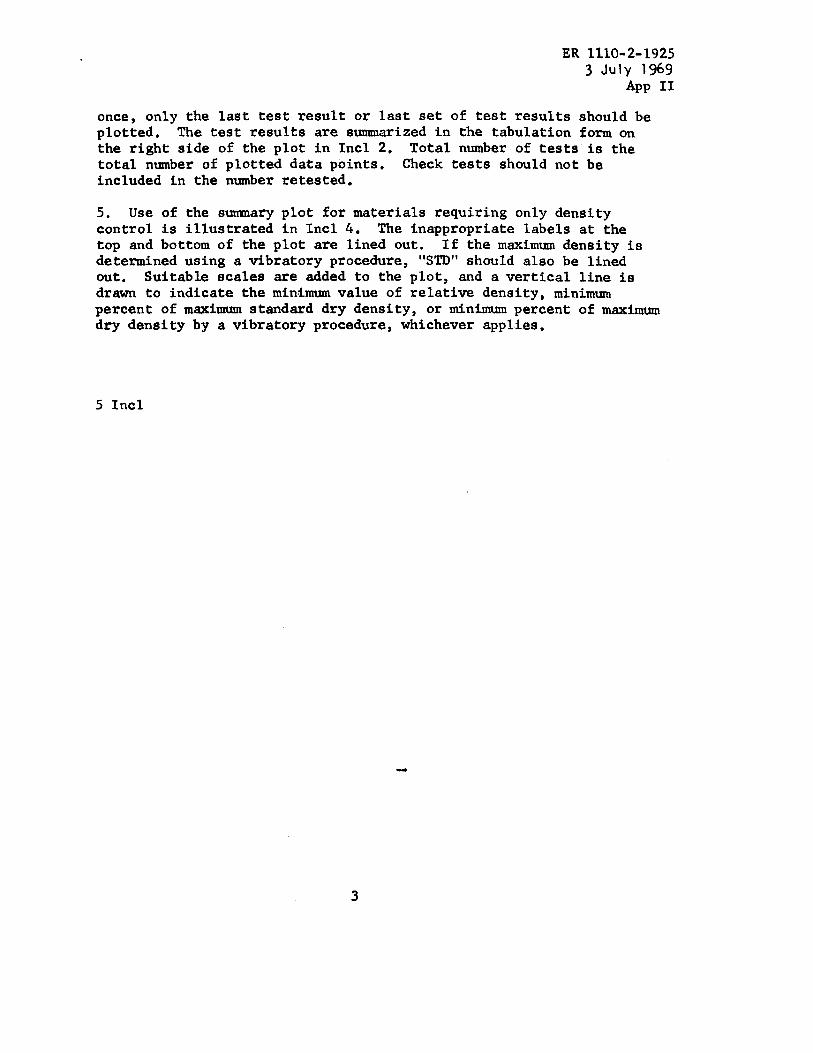
5. Use of the sumnary plot for materials requiring only densitycontrol is illustrated in Incl 4. The inappropriate labels at thetop and bottom of the plot are lined out. If the maximum density isdetermined using a vibratory procedure, “STD” should also be linedout● Suitable scales are added to the plot, and a vertical line isdrawn to indicate the minimum value of relative density, minimumpercent of maximum standard dry density, or minimum percent of maximumdry density by a vibratory procedure, whichever applies.
5 Incl
.
3
El:1110-?-19253 July 1969App 11
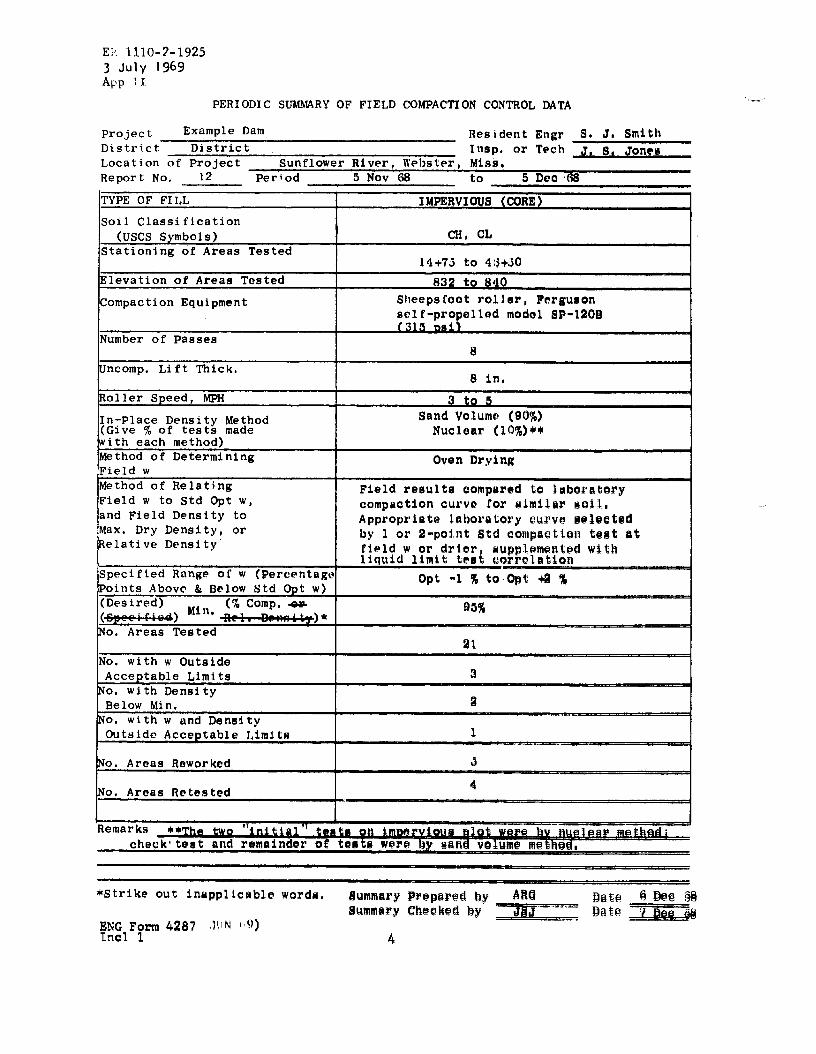
PERIODIC SW~RY OF FIELD
Project Example Dam
cOMPACTTON CONTROL DATA
Resident Engr _S. J, SmithDistrict District Insp. or Tech J, s, Jon@@Location of Project Sunflower River, lVt?lJster,Miss.Report No, 12 Period 5 Nov C* to S Deo’S8
TYPE OF FILL
Soil Classification
(USCS Symbols)Stationing of Areas Tested
Elevation of Areas Tested
Compaction Equipment
Number of Passes
ncomp. Lift Thick,
!-Roller Speed, MPH
In-Place Density Method(Give % of tests madewith each method)Method of DeterminingField wMethod of Relat~ngField w to Std Opt w,and Field Density toMax. Dry Density, orRelative Density’
Specified Range of’w (Percentage
1oints Above & Below Std opt w)(Desired)
Min. (%c~mpo +(~) ~)*o. Areas Tested
No. with w OutsideAcceptable LimitsNo. with DensityBelow Min.
No. with w and DensityOutside Acceptable Limits
No. Areas Reworked
Po. Areas Retested
I (
check” teat and remainder of
IMPERVIOUS (CORE)
CH, CL
14+75 to 4(3+30
832 to 840Slleepscootroller, Fergusonself-propellod modol SP-120B
8
8 in,
3 to 5Sand Volume (90%)Nuclear (LO%)**
Oven Drying
3
-
ER 1110-2-1925
+.-
i.J-.
1’I-.
—-1-
.!.
k
.
-t-
.,. ~.
–-t ---
1;,*“1. ..1..
–i_
1I1-
.
..1
.4
. .
1
t

:R 111o-2-19251 July 1969LppII
PERIODIC SUMMARY OF FIELD COMPACTION CONTROL DATA
reject Example Dam Resident Engr J. S. Smith
istrict ulstrlct Insp. or Tech S. J. Jonesocation of Project nSu flower R , Webs . Miss.iver tereport No. 12 Period 5 Nov 6S to 5Dec 6S
YPE OF FILL
oil Classification(USCS Symbols)tationing of Areas Tested
levation of Areas Tested
ompaction Equipment
umber of Passes
ncomp. Lift Thick.
oiler Speed, MPN
n-Place Density MethodGive % of tests madeith each method)Iethod of Determining‘ieldwIethod of Relating‘ieldw to Std Opt w,Ind Field Density tofax. Dry Density, orIelative Density
;pecified Range of w (Percentag(~oints Above & Below Std opt w)~Desired) ~ln (~. .~) “ Rel. Density)*lo. Areas Tested
to. with w OutsideAcceptable Limitsio. with DensityBelow Min.To. with w and Dens!ityOutside Acceptable Limits
To. Areas Reworked
To. Areas Retested
~emarks **The two initial tf
PERVIWS (SAND DRAIN)
Sw
15+50 to 37+50830 to 839
Vibratory Roller, Tampo Model VC80(static wt. = 3.5 tons, centrifu alforce of 7.5 tons at 1600 rDm)
F
4
2Sand Volume (90%)
Nuclear (10%)
Visual Observation
Field results compared to results oflaboratory maximum (modified Providencevibrated) and minimum density tests onsimilar material. Appropriate laboratoryresults selected by gradation correlation.
Saturated during compaction
80%
25
Not Applicable
6
Not Applicable
3
Its on pervious plot were by nuclear method..—.
Check tests and all other tests w~re by the sand volume method.
~Strike out inapplicable words. Summary Prepared by ARG Date 5 Dec 38ENG Form 4287 (JUN 69) Summary Checked by JSJ Date ( uec 6sIncl 3 6
,,
PROJECT:
EXAMPLE
DAM
DISTRICT:
DISTRICT
REPORT
PERIOD:
5NOV
-5
DEC
68
~.~RIAL
:PERVIOUS
(SAND
DRAIN)
CUmTI
VZ
TO
THIS
mI
sREPORT
REPORT
TOTAL
?JO.OF
TESTS
175
.?5
—.
ACCEPTABLE
MIN
.4CCE~ABLX
3fIl?
~WORKED
ONLY
(NOR.ETEST)
~WOR~D
&RETESTED
.—.—
—x,
,X2MTER
@,,@z~SULT
OF
RETEST
A~R
REWORKING
~:.l
,;-,.. -.
—-
.
z
Al,h2INITIAL
TEST
(U=
O-NLYw/CIiECKTEST)
l...-
.i.i.
..,.
-.i-
..:....k....i.-L
-....—....
L..
i-..*
*—+
—...
_._
—h
_
!.
J-.
.l..
..
..
..
..
..
...l
..
..l.
-.d.
..QJ
..
..
L.-+
...*+
-*-t
.=i
..7.
+...
,
—
A,,A2~CK
TEST
NOTE:
USE
Am
(RELATIVEDENSITY,Dd
,PER~NT)
AND
(PERCENTOFMAX
(STD)DRYDEN)
R 1110-2-1925July 1969
pp 11
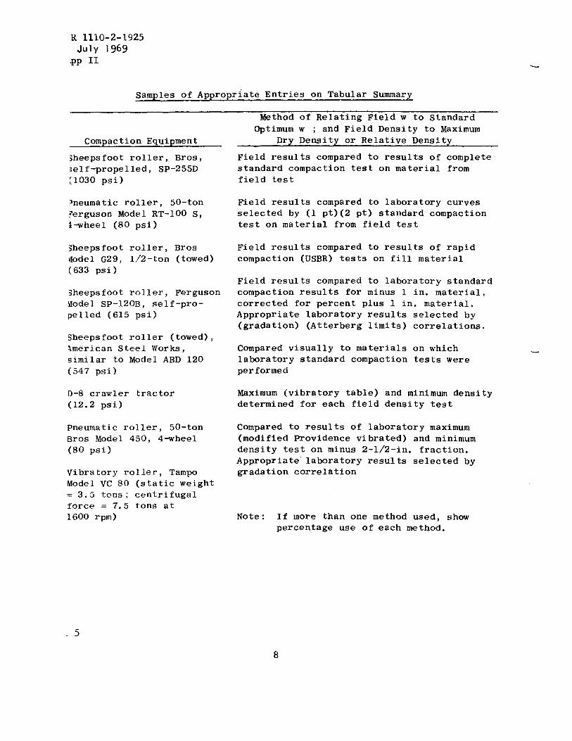
Samples of Appropriate Entries on Tabular Summary
Method of Relating Field w to Standard
Compaction Equipment
sheepsfoot roller, Bros,self-propelled, SP-255D[1030 psi)
?neumatic roller, 50-ton?erguson Model RT-1OO S,l-wheel (80 psi)
Sheepsfoot roller, BrostiodelG29, l/2-ton (towed)(633 psi)
Sheepsfoot roller, FergusonModel SP-120B, self-pro-pelled (615 psi)
5heepsfoot roller (towed),tmerican Steel Works,similar to Model ABD 120(547 psi)
D-8 crawler tractor(12.2 psi)
Pneumatic roller, 50-tonBros Model 450, 4-wheel(80 psi)
Vibratory roller, TampoModel VC 90 (static weight= 3.5 tons; centrifugalforce = 7.5 tons at1600 rpm)
Optimum w ; and Field Density to MaximumDry Density or Relative Density
Field results compared to results of completestandard compaction test on material fromfield test
Field results compared to laboratory curvesselected by (1 pt)(2 pt) standard compactiontest on material from field test
Field results compared to results of rapidcompaction (USBR) tests on fill material
Field results compared to laboratory standardcompaction results for minus 1 in. material,corrected for percent plus 1 in. material.Appropriate laboratory results selected by(gradation) (Atterberg limits) correlations.
Compared visually to materials on whichlaboratory standard compaction tests wereperformed
Maximum (vibratory table) and minimum densitydetermined for each field density test
Compared to results of laboratory maximum(modified Providence vibrated) and minimumdensity test on minus 2-1/2-in. fraction.Appropriate” laboratory results selected bygradation correlation
Note : If lflorethan one method used, showpercentage use of each method.
L
.5
ER 1110-2-19253 July 1969
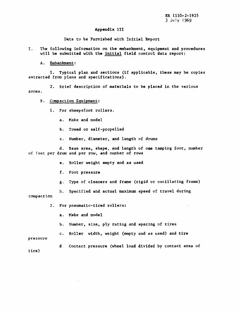
Appendix III
Data to be Furnished with Initial Report
1. The following information on the embankment, equipment and procedureswill be submitted with the initial field control data report:
A. Embankment:
1. Typical plan and sections (if applicable, these may be copiesextracted from plans and specifications).
2. Brief description of materials to be placed in the variouszones.
B. Compaction Equipment:
1. For sheepsfoot rollers.
a, Make and model
b. Towed or self-propelled
c. Number, diameter, and length of drums
d. Base area, shape, and length of o- tamping foot, numberof feet per drum and per row, and number of rows
e, Roller weight empty and as used
f. Foot pressure
g“ Type of cleaners and frame (rigid or oscillating frame)
h. Specified and actual maximum speed of travel duringcompaction
2. For pneumatic-tired rollers:
a. Make and model
b. Number, size, ply rating and spacing of tires
c. Roller width, weight (empty and as used) and tirepressure
d Contact pressure (wheel load divided by contact area oftire)

ER 1110-2-19253 July 1969App III
e.compaction.
3. For
a.
b.
c.
d.
e.
f.rockfill within
Specified and actual maximum speed of travel during,
vibratory rollers:
Make and model
Towed or self-propelled
Number, diameter and length of drums
Static roller weight empty and with ballast
Dynamic pressure exerted
Vibrating frequency (report frequency of roller and2 feet of roller)
c. Summary of Test Procedures:
1.content ~or
2.curves used
Method of correcting field and laboratory density and watermaterial having plus 3/4” particle sizes.
Graphical presentation of compaction curves or other referencefor correlating field with laboratory density and water content. .
Description of procedures for selecting appropriate laboratorymaximum density and optimum-water content for comparison with in-place data.
II. The following information on the instrumentationwill be submittedwith the initial field control data report:
A. Piezometers:
1. The type (e.g. USBR, Warlam, Hall,tip dimensions and description of the componentand type of porous stone, slot or screen size).
Casagrande, Wellpoint, etc.),parts of the tip (e.g. size
2. The type, wall thickness and inside diameter of pipe ortubing and method of joining sectiops.
3. The type, thickness, method of placement, gradation and topand bottom elevation of the filter surrounding the piezometer tip.
2

ER.1110-2-19253 July 1969
App III
4. The type, thickness, method of placement and top andbottom elevations of the seal.
5. Type of gage and method of protection.
6. The type of surface protection, (e.g. shelter facilities,posts, etc.) date of installation, schedule of observations and problemsencountered during installation and operation.
7. Plan and elevations showing location of piezometers.
B. Settlement Plates:
1. Description of settlement gage (e.g. dimensions, type, etc.)
with a detailed drawing.
2. Type and size of riser pipe and method of joining sections.
3. Procedures for installation of instruments and obtainingmeasurements.
4. Plan and elevations showing locations of settlement plates.
c, Surface Reference Monuments:
1. Description of reference points (e.g. dimensions, type,depth of embedment, protection against damage, etc.) with a detaileddra”~ing.
2. Description of bench marks.
3. Plan and elevations of reference points and bench marks.
3
Recommended