© 2004 Hewlett-Packard Development Company, L.P.The information contained herein is subject to change without notice
Disaster-Tolerant Cluster Technology and Implementation
Keith ParrisSystems/Software EngineerHewlett-Packard

2
Topics
• Terminology: HA, FT, DR, DT
• Disaster Recovery cf. Disaster Tolerance
• Basis for Disaster Tolerance:− Cluster technology, operating system platforms, multi-
site clusters, and inter-site links− Foundation requirements, and planning for disaster
tolerance− Data replication methods− Quorum schemes and data protection
• Real-Life Examples
• Business Continuity

3
High Availability (HA)• Ability for application processing to continue with
high probability in the face of common (mostly hardware) failures
• Typical technologies:− Redundant power supplies and fans− RAID for disks− Clusters of servers− Multiple NICs, redundant routers− Facilities: Dual power feeds, n+1 Air Conditioning
units, UPS, generator

4
Fault Tolerance (FT)• Ability for a computer system to continue
operating despite hardware and/or software failures
• Typically requires:− Special hardware with full redundancy, error-checking,
and hot-swap support− Special software
• Provides the highest availability possible within a single datacenter

5
Disaster Recovery (DR)• Disaster Recovery is the ability to resume
operations after a disaster− Disaster could be as bad as destruction of the entire
datacenter site and everything in it− But many events short of total destruction can also
disrupt service at a site:• Power loss in the area for an extended period of time• Bomb threat (or natural gas leak) prompting evacuation of
everyone from the site• Water leak• Air conditioning failure
6
Disaster Recovery (DR)• Basic principle behind Disaster Recovery:
− To be able to resume operations after a disaster implies off-site data storage of some sort

7
Disaster Recovery (DR)• Typically,
− There is some delay before operations can continue (many hours, possibly days), and
− Some transaction data may have been lost from IT systems and must be re-entered
• Success hinges on ability to restore, replace, or re-create:
• Data (and external data feeds)• Facilities• Systems• Networks• User access
8
DR Methods− Tape Backup− Vendor Recovery Site− Data Vaulting− Expedited hardware replacement− Hot Site

9
DR Methods:Tape Backup• Data is copied to tape, with off-site storage at a
remote site
• Very-common method. Inexpensive.
• Data lost in a disaster is: − All the changes since the last tape backup that is
safely located off-site
• There may be significant delay before data can actually be used

10
DR Methods:Vendor Recovery Site• Vendor provides datacenter space, compatible
hardware, networking, and sometimes user work areas as well− When a disaster is declared, systems are configured
and data is restored to them
• Typically there are hours to days of delay before data can actually be used

11
DR Methods:Data Vaulting• Copy of data is saved at a remote site
− Periodically or continuously, via network− Remote site may be own site or at a vendor location
• Minimal or no data may be lost in a disaster
• There is typically some delay before data can actually be used
12
DR Methods:Expedited Hardware Replacement• Vendor agrees that in the event of a disaster, a
complete set of replacement hardware will be shipped to the customer within a specified (short) period of time− HP has Quick Ship program
• Typically there would be at least several days of delay before data can be used

13
DR Methods:Hot Site• Company itself (or a vendor) provides pre-
configured compatible hardware, networking, and datacenter space
• Systems are pre-configured, ready to go− Data may already resident be at the Hot Site thanks to
Data Vaulting
• Typically there are minutes to hours of delay before data can be used

14
Disaster Tolerance vs.Disaster Recovery• Disaster Recovery is the ability to resume
operations after a disaster.
• Disaster Tolerance is the ability to continueoperations uninterrupted despite a disaster.
15
Disaster Tolerance Ideals• Ideally, Disaster Tolerance allows one to
continue operations uninterrupted despite a disaster:− Without any appreciable delays− Without any lost transaction data

16
Disaster Tolerance vs. Disaster Recovery• Businesses vary in their requirements with
respect to:− Acceptable recovery time− Allowable data loss
• So some businesses need only Disaster Recovery, and some need Disaster Tolerance− And many need DR for some (less-critical) functions
and DT for other (more-critical) functions
• Basic Principle: Determine requirements based on business needs first,− Then find acceptable technologies to meet the needs
of each area of the business

17
Disaster Tolerance and Business Needs• Even within the realm of businesses needing
Disaster Tolerance, business requirements vary with respect to:− Acceptable recovery time− Allowable data loss
• Technologies also vary in their ability to achieve the Disaster Tolerance ideals of no data loss and zero recovery time
18
Quantifying Disaster Tolerance and Disaster Recovery Requirements• Commonly-used metrics:
− Recovery Point Objective (RPO):• Amount of data loss that is acceptable, if any
− Recovery Time Objective (RTO):• Amount of downtime that is acceptable, if any
19
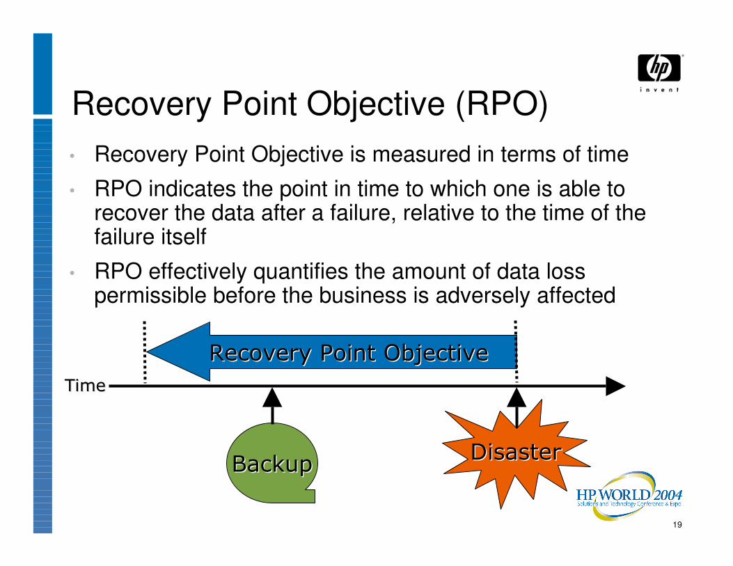
Recovery Point Objective (RPO)• Recovery Point Objective is measured in terms of time
• RPO indicates the point in time to which one is able to recover the data after a failure, relative to the time of the failure itself
• RPO effectively quantifies the amount of data loss permissible before the business is adversely affected
����������������������
��������������������� ���������������������
��������

20
Recovery Time Objective (RTO)• Recovery Time Objective is also measured in terms of
time
• Measures downtime:− from time of disaster until business can continue
• Downtime costs vary with the nature of the business, and with outage length
���������� ����������
���� ����
��������������������� ���������������������
��������
21
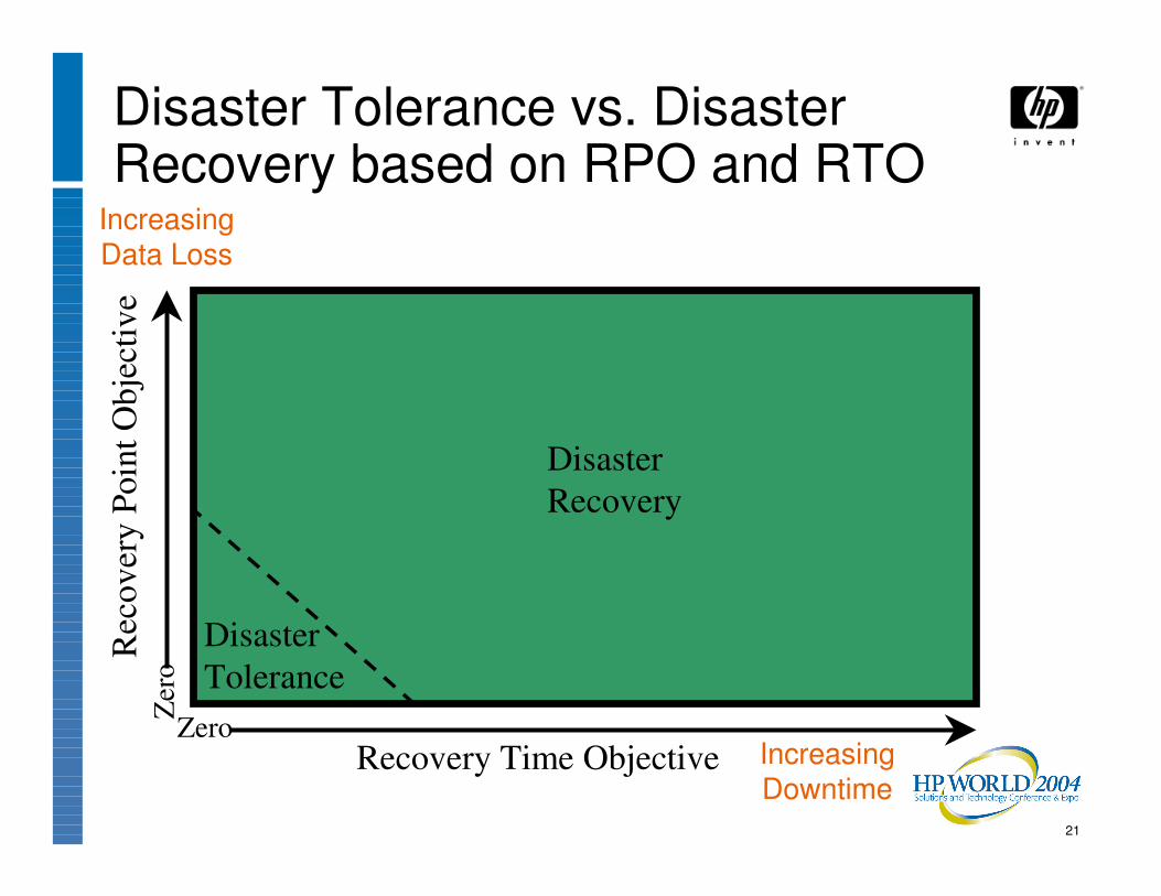
Disaster Tolerance vs. Disaster Recovery based on RPO and RTO
Disaster Tolerance
Recovery Time Objective
Rec
over
y Po
int O
bjec
tive
Zero
Zer
o
Disaster Recovery
Increasing Data Loss
Increasing Downtime

22
Examples of Business Requirements and RPO / RTO Values• Greeting card manufacturer
− RPO = zero; RTO = 3 days
• Online stock brokerage− RPO = zero; RTO = seconds
• ATM machine− RPO = hours; RTO = minutes
• Semiconductor fabrication plant− RPO = zero; RTO = minutes
• but data protection by geographical separation is not needed

23
Recovery Point Objective (RPO)• RPO examples, and technologies to meet them:
− RPO of 24 hours:• Backups at midnight every night to off-site tape drive, and
recovery is to restore data from set of last backup tapes− RPO of 1 hour:
• Ship database logs hourly to remote site; recover database to point of last log shipment
− RPO of a few minutes:• Mirror data asynchronously to remote site
− RPO of zero:• Mirror data strictly synchronously to remote site

24
Recovery Time Objective (RTO)• RTO examples, and technologies to meet them:
− RTO of 72 hours:• Restore tapes to configure-to-order systems at vendor DR
site− RTO of 12 hours:
• Restore tapes to system at hot site with systems already in place
− RTO of 4 hours:• Data vaulting to hot site with systems already in place
− RTO of 1 hour:• Disaster-tolerant cluster with controller-based cross-site disk
mirroring

25
Recovery Time Objective (RTO)• RTO examples, and technologies to meet them:
− RTO of 10 seconds:• Disaster-tolerant cluster with:
− Redundant inter-site links, carefully configured• To avoid bridge Spanning Tree Reconfiguration delay
− Host-based software mirroring for data replication• To avoid time-consuming manual failover process
with controller-based mirroring− Tie-breaking vote at a 3rd site
• To avoid loss of quorum after site failure− Distributed Lock Manager and Cluster-Wide File
System (or the equivalent in the database), allowing applications to run at both sites simultaneously
• To avoid having to start applications at failover site after the failure
26
Technologies• Clustering
• Inter-site links
• Foundation and Core Requirements for Disaster Tolerance
• Data replication schemes
• Quorum schemes

27
Clustering• Allows a set of individual computer systems to
be used together in some coordinated fashion
28
Cluster types• Different types of clusters meet different needs:
− Scalability clusters allow multiple nodes to work on different portions of a sub-dividable problem
• Workstation farms, compute clusters, Beowulf clusters− Availability clusters allow one node to take over
application processing if another node fails
• For Disaster Tolerance, we’re talking primarily about Availability clusters− (geographically dispersed)

29
High Availability Clusters• Transparency of failover and degrees of
resource sharing differ:− “Shared-Nothing” clusters− “Shared-Storage” clusters− “Shared-Everything” clusters

30
“Shared-Nothing” Clusters• Data may be partitioned among nodes
• Only one node is allowed to access a given disk or to run a specific instance of a given application at a time, so:− No simultaneous access (sharing) of disks or other
resources is allowed (and this must be enforced in some way), and
− No method of coordination of simultaneous access (such as a Distributed Lock Manager) exists, since simultaneous access is never allowed

31
“Shared-Storage” Clusters• In simple “Fail-over” clusters, one node runs an
application and updates the data; another node stands idly by until needed, then takes over completely
• In more-sophisticated clusters, multiple nodes may access data, but typically one node at a time “serves” a file system to the rest of the nodes, and performs all coordination for that file system

32
“Shared-Everything” Clusters• “Shared-Everything” clusters allow any
application to run on any node or nodes− Disks are accessible to all nodes under a Cluster File
System− File sharing and data updates are coordinated by a
Lock Manager
33
Cluster File System• Allows multiple nodes in a cluster to access data
in a shared file system simultaneously
• View of file system is the same from any node in the cluster
34
Distributed Lock Manager• Allows systems in a cluster to coordinate their
access to shared resources, such as:− Mass-storage devices (disks, tape drives)− File systems− Files, and specific data within files− Database tables

35
Disaster-Tolerant HP Platforms−OpenVMS−HP-UX and Linux−Tru64−NonStop−Microsoft

36
OpenVMS
Controller-based data replication, e.g. StorageWorks Continuous Access
OpenVMS Volume Shadowing Software for host-based mirroring
Reliable Transaction Router (RTR) middleware
Database replication or log shipping
OpenVMS Cluster Software
Data ReplicationClustering Software

37
HP-UX and Linux
MirrorDisk/UX for host-based software mirroring
Database replication or log shipping
MC/ServiceGuard
CampusCluster or
Extended SAN Cluster
StorageWorks XP Continuous Access or EMC SRDF for controller-based data replicationDatabase replication or log shipping
MC/ServiceGuard
MetroCluster or
ContinentalCluster
Data ReplicationClustering Software

38
Tru64
Database replication or log shipping
Veritas VxVM with Volume Replicator option
StorageWorks Continuous Access
Reliable Transaction Router (RTR) middleware
TruCluster
Data ReplicationClustering Software

39
NonStop
Remote Database Facility (RDF) layered on Transaction Management Facility (TMF)
•plus AutoTMF for non-TMF applications
•and AutoSYNC for non-database files
•with RDF/ZLT (Zero Lost Transactions) if RPO of zero is required
NonStop Kernel Software with Metroclusters (limited distance) or Continentalclusters(unlimited distance)
Data ReplicationClustering Software

40
Microsoft
Solutions qualified and listed in the Microsoft Windows Server Catalog (formerly HCL) under Geographically Dispersed Cluster Solutions
Reliable Transaction Router (RTR) middleware
Windows 2000 Server or Windows Server 2003 with Microsoft Cluster Services (MSCS)
Data ReplicationClustering Software
41
Multi-Site Clusters• Consist of multiple sites with one or more
systems, in different locations
• Systems at each site are all part of the same cluster
• Sites are typically connected by bridges (or bridge-routers; pure routers don’t pass the special cluster protocol traffic required for most clusters)

42
Multi-Site Clusters:Inter-site Link(s)• Sites linked by:
− DS-3/T3 (E3 in Europe) or ATM circuits from a TelCo− Microwave link: DS-3/T3 (E3) or Ethernet− Free-Space Optics link (short distance, low cost)− “Dark fiber” where available:
• Ethernet over fiber (10 mb, Fast, Gigabit)• FDDI• Fibre Channel

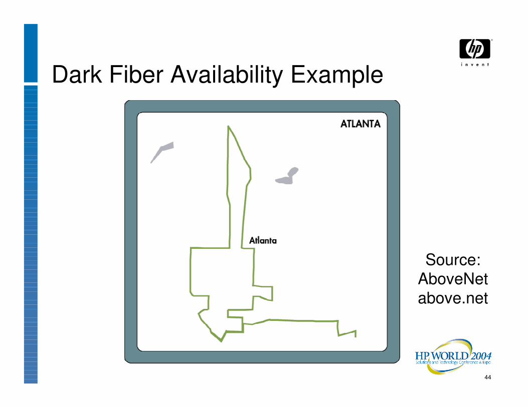
43
Dark Fiber Availability Example
Source: AboveNetabove.net
44
Dark Fiber Availability Example
Source: AboveNetabove.net
45
Inter-site Link Options• Sites linked by:
− Wave Division Multiplexing (WDM), in either Coarse (CWDM) or Dense (DWDM) Wave Division Multiplexing flavors
• Can carry any of the types of traffic that can run over a single fiber
− Individual WDM channel(s) from a vendor (called “lambdas”), rather than entire dark fibers

46
Bandwidth of Inter-Site Link(s)
Multiples of ATM, GbE, FC, etc.[D]WDM
1 or 2 GbFibre Channel
Regular: 10 Mb
Fast: 100 Mb
Gigabit: 1 Gb
Ethernet
155 Mb (OC-3) or
622 Mb (OC-12)ATM
45 MbDS-3 (a.k.a. T3)
BandwidthLink Type

47
Inter-Site Link Choices
• Service type choices− Telco-provided data circuit service, own
microwave link, FSO link, dark fiber?− Dedicated bandwidth, or shared pipe?− Single or multiple (redundant) links? If
redundant links, then:• Diverse paths?• Multiple vendors?

48
Disaster-Tolerant Clusters:Foundation• Goal: Survive loss of up to one entire datacenter
• Foundation:− Two or more datacenters a “safe” distance apart− Cluster software for coordination− Inter-site link for cluster interconnect− Data replication of some sort for 2 or more identical
copies of data, one at each site:• Host-based mirroring software, controller-based data
replication (e.g. Continuous Access), database replication, replicating middleware (e.g. Reliable Transaction Router), etc.

49
Disaster-Tolerant Clusters:Foundation• Foundation:
− Management and monitoring tools• Remote system console access or KVM system• Failure detection and alerting, for things like:
� Network (especially inter-site link) monitoring� Mirrorset member loss� Node failure
• Quorum recovery tool or mechanism (for 2-site clusters with balanced votes)

50
Disaster-Tolerant Clusters:Foundation• Foundation:
− Configuration planning and implementation assistance, and staff training
• HP recommends HP consulting services for this

51
Disaster-Tolerant Clusters:Foundation• Foundation:
− Carefully-planned procedures for:• Normal operations• Scheduled downtime and outages• Detailed diagnostic and recovery action plans for
various failure scenarios
52
Disaster-Tolerant Clusters:Foundation• Foundation:
− Data Replication:• Data is constantly replicated to or copied to a 2nd site, so data
is preserved in a disaster− Solution must also be able to redirect applications and
users to the site with the up-to-date copy of the data

53
Disaster-Tolerant Clusters:Foundation• Foundation:
− Complete redundancy in facilities and hardware:• Second site with its own storage, networking, computing
hardware, and user access mechanisms in place• Sufficient computing capacity is in place at the 2nd site to
handle expected workloads by itself if the 1st site is destroyed• Monitoring, management, and control mechanisms are in
place to facilitate fail-over

54
Planning for Disaster Tolerance• Remembering that the goal is to continue
operating despite loss of an entire datacenter− All the pieces must be in place to allow that:
• User access to both sites• Network connections to both sites• Operations staff at both sites
− Business can’t depend on anything that is only at either site
55
Planning for DT: Site SelectionSites must be carefully selected:
• Avoid hazards− Especially hazards common to both (and the loss of
both datacenters at once which might result from that)
• Make them a “safe” distance apart
• Select site separation in a “safe” direction
56
Planning for DT: What is a “Safe Distance”• Analyze likely hazards of proposed sites:
− Fire (building, forest, gas leak, explosive materials)− Storms (Tornado, Hurricane, Lightning, Hail, Ice)− Flooding (excess rainfall, dam breakage, storm surge,
broken water pipe)− Earthquakes, Tsunamis
57
Planning for DT: What is a “Safe Distance”• Analyze likely hazards of proposed sites:
− Nearby transportation of hazardous materials (highway, rail)
− Terrorist (or disgruntled customer) with a bomb or weapon
− Enemy attack in war (nearby military or industrial targets)
− Civil unrest (riots, vandalism)
58
Planning for DT: Site Separation Distance• Make sites a “safe” distance apart
• This must be a compromise. Factors:− Risks− Performance (inter-site latency)− Interconnect costs− Ease of travel between sites− Availability of workforce
59
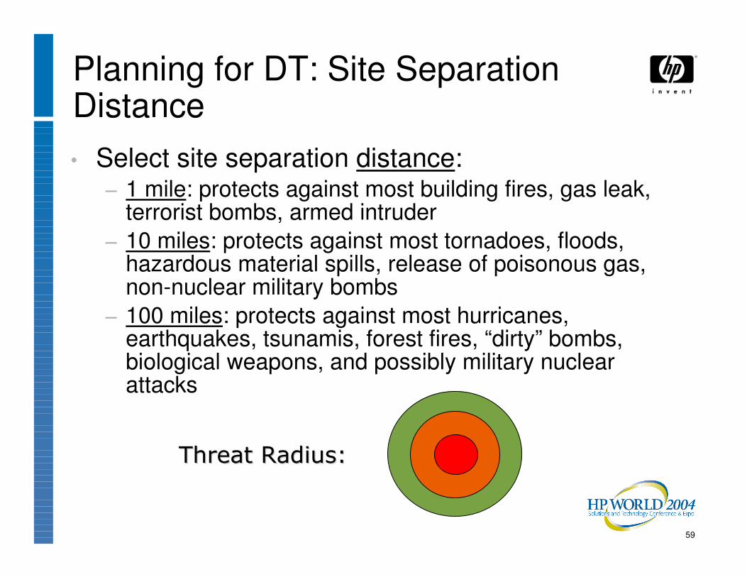
Planning for DT: Site Separation Distance• Select site separation distance:
− 1 mile: protects against most building fires, gas leak, terrorist bombs, armed intruder
− 10 miles: protects against most tornadoes, floods, hazardous material spills, release of poisonous gas, non-nuclear military bombs
− 100 miles: protects against most hurricanes, earthquakes, tsunamis, forest fires, “dirty” bombs, biological weapons, and possibly military nuclear attacks
������ ����������� �����

60
Planning for DT: Site Separation Direction• Select site separation direction:
− Not along same earthquake fault-line− Not along likely storm tracks− Not in same floodplain or downstream of same dam− Not on the same coastline− Not in line with prevailing winds (that might carry
hazardous materials)

61
Planning for Disaster Tolerance:Providing Redundancy
• Redundancy must be provided for:− Datacenter and facilities (A/C, power, user workspace,
etc.)− Data
• And data feeds, if any− Systems− Network− User access and workspace− Workers themselves
62
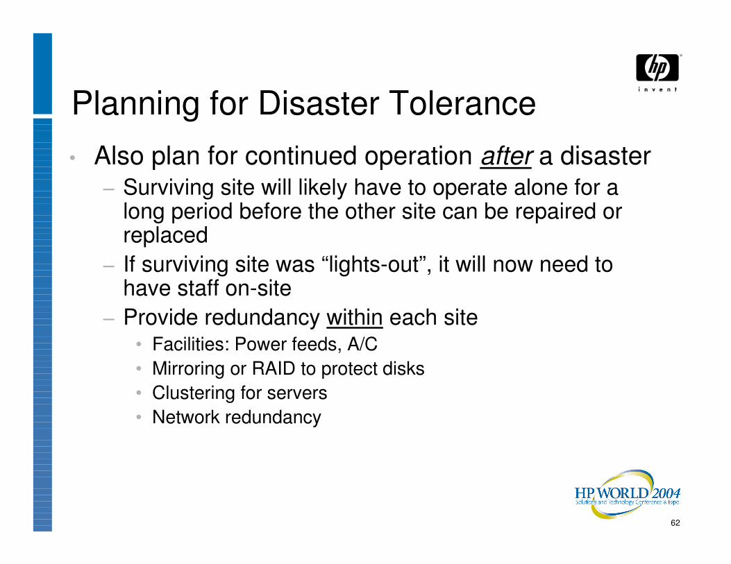
Planning for Disaster Tolerance• Also plan for continued operation after a disaster
− Surviving site will likely have to operate alone for a long period before the other site can be repaired or replaced
− If surviving site was “lights-out”, it will now need to have staff on-site
− Provide redundancy within each site• Facilities: Power feeds, A/C• Mirroring or RAID to protect disks• Clustering for servers• Network redundancy
63
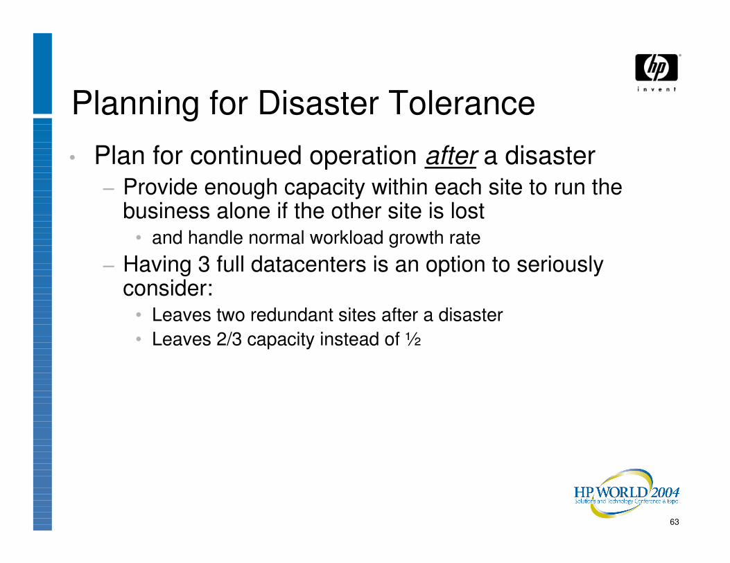
Planning for Disaster Tolerance• Plan for continued operation after a disaster
− Provide enough capacity within each site to run the business alone if the other site is lost
• and handle normal workload growth rate− Having 3 full datacenters is an option to seriously
consider:• Leaves two redundant sites after a disaster• Leaves 2/3 capacity instead of ½

64
Cross-site Data Replication Methods• Hardware
− Storage controller
• Software− Host software disk mirroring, duplexing, or volume
shadowing− Database replication or log-shipping− Transaction-processing monitor or middleware with
replication functionality
65
Data Replication in Hardware• HP StorageWorks Continuous Access (CA)
(formerly Data Replication Manager, DRM)
• HP XP Series with Continuous Access XP
• EMC Symmetrix Remote Data Facility (SRDF)

66
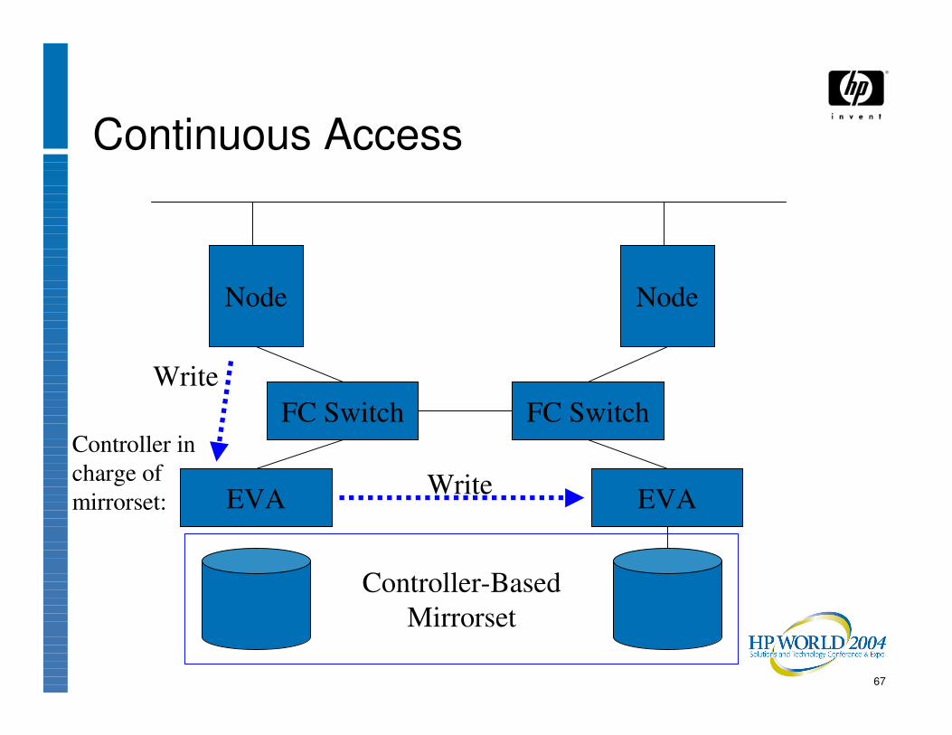
Continuous Access
Node
FC Switch
Node
FC Switch
Controller-BasedMirrorset
EVA EVA
67
Continuous Access
Node
FC Switch
Node
FC Switch
EVA EVA
Controller in charge of mirrorset:
Write
Write
Controller-BasedMirrorset

68
Continuous Access
Node
FC Switch
Node
FC Switch
EVA EVA
I/O
I/OController in charge of mirrorset:
Controller-BasedMirrorset
69
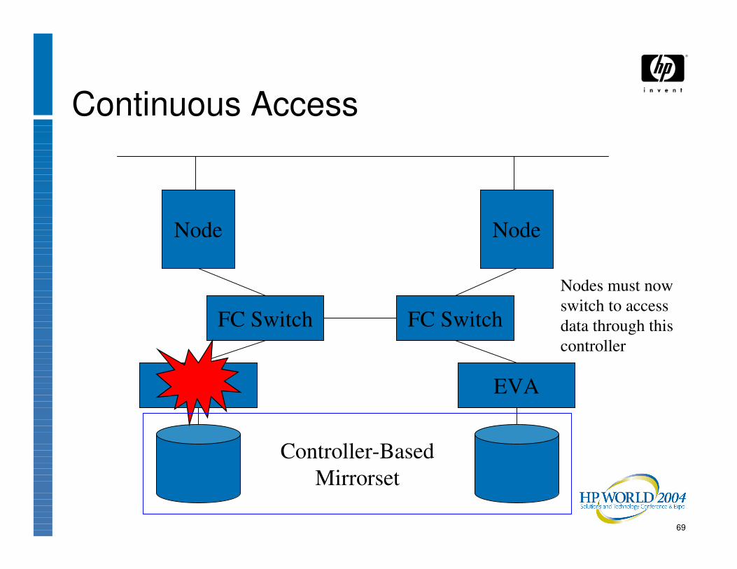
Continuous Access
Node
FC Switch
Node
FC Switch
EVA EVA
Nodes must now switch to access data through this controller
Controller-BasedMirrorset
70
Data Replication in Software• Host software disk mirroring or shadowing:
− Volume Shadowing Software for OpenVMS− MirrorDisk/UX for HP-UX− Veritas VxVM with Volume Replicator extensions for
UNIX and Windows
71
Data Replication in Software• Database replication or log-shipping
− Replication within the database software• Remote Database Facility (RDF) on NonStop• Oracle DataGuard (Oracle Standby Database)
− Database backups plus “Log Shipping”
72
Data Replication in Software• TP Monitor/Transaction Router
− e.g. HP Reliable Transaction Router (RTR) Software on OpenVMS, UNIX, Linux, and Windows

73
Data Replication in Hardware• Data mirroring schemes
− Synchronous• Slower, but less chance of data loss
� Beware: some solutions can still lose the last write operation before a disaster
− Asynchronous• Faster, and works for longer distances
� but can lose minutes’ worth of data (more under high loads) in a site disaster

74
Data Replication in Hardware− Mirroring is of sectors on disk
• So operating system / applications must flush data from memory to disk for controller to be able to mirror it to the other site

75
Data Replication in Hardware− Resynchronization operations
• May take significant time and bandwidth• May or may not preserve a consistent copy of data at the
remote site until the copy operation has completed• May or may not preserve write ordering during the copy

76
Data Replication in Hardware:Write Ordering
• File systems and database software may make some assumptions on write ordering and disk behavior− For example, a database may write to a journal log, let
that I/O complete, then write to the main database storage area
• During database recovery operations, its logic may depend on these writes having completed in the expected order

77
Data Replication in Hardware:Write Ordering in Steady State
• Some controller-based replication methods copy data on a track-by-track basis for efficiency instead of exactly duplicating individual write operations− This may change the effective ordering of write
operations within the remote copy
• Some controller-based replication products can preserve write ordering− Some even across a set of different disk volumes
78
Data Replication in Hardware:Write Ordering during Re-Synch• When data needs to be re-synchronized at a
remote site, some replication methods (both controller-based and host-based) similarly copy data on a track-by-track basis for efficiency instead of exactly duplicating writes
• This may change the effective ordering of write operations within the remote copy
• The output volume may be inconsistent and unreadable until the resynchronization operation completes

79
Data Replication in Hardware:Write Ordering during Re-Synch• It may be advisable in this case to preserve an
earlier (consistent) copy of the data, and perform the resynchronization to a different set of disks, so that if the source site is lost during the copy, at least one copy of the data (albeit out-of-date) is still present
������������������ ����������������������
����������������
� ��� ���� ����
������������������
���� ���� ���� ����

80
Data Replication in Hardware:Performance
• Replication performance may be affected by latency due to the speed of light over the distance between sites− Greater (safer) distances between sites implies
greater latency
Speed of light: 186,000 miles per second in a vacuum.Minimum 1 round-trip required between sites.

81
Data Replication in Hardware: Performance
• Re-synchronization operations can generate a high data rate on inter-site links
• Excessive re-synchronization time increases Mean Time To Repair (MTTR) after a site failure or outage
• Acceptable re-synchronization times and link costs may be the major factors in selecting inter-site link(s)

82
Data Replication in Hardware:Performance
• With some solutions, it may be possible to synchronously replicate data to a nearby “short-haul” site, and asynchronously replicate from there to a more-distant site− This is sometimes called “cascaded” data replication
���� ���� �������� �������������������������������� ��������������
!""�����!""����� !#"""�����!#"""�����
��� �����$���$��� %��&%��&��$���$���

83
Data Replication in Hardware:Copy Direction
− Most hardware-based solutions can only replicate a given set of data in one direction or the other
− Some can be configured replicate some disks on one direction, and other disks in the opposite direction
• This way, different applications might be run at each of the two sites
�������������� �������� �������� ��������� ���������
�������� �������� �������������� ��������� ���������
���� ���� ���� ����
������������������
������������������

84
Data Replication in Hardware:Data Access at Remote Site
− All access to a disk unit is typically from one controller at a time
• So, for example, Oracle Parallel Server can only run on nodes at one site at a time
• Read-only access may be possible at remote site with some products
• Failover involves controller commands� Manual, or scripted (but still take some time to perform)
�������������� �������� �������� ��������� ���������
���� ���� ���� ����
����������������'��'��
��������

85
Data Replication in Hardware: Multiple Target Disks
− Some products allow replication to:• A second unit at the same site• Multiple remote units or sites at a time (MxN configurations)

86
Data Replication:Copy Direction
− A very few solutions can replicate data in both directions simultaneously on the same mirrorset
� e.g. Volume Shadowing in OpenVMS Clusters• Host software must coordinate any disk updates to the same
set of disk blocks from both sites� e.g. Distributed Lock Manager in OpenVMS Clusters, or
Oracle RAC or Oracle Parallel Server• This allows the same application to be run on cluster nodes at
both sites at once
Server Server
I/Os
Coordination
87
Managing Replicated Data• With copies of data at multiple sites, one must
take care to ensure that:− Both copies are always equivalent, or, failing that,
• Users always access the most up-to-date copy

88
Managing Replicated Data• If the inter-site link fails, both sites might
conceivably continue to process transactions, and the copies of the data at each site would continue to diverge over time
• This is called “Split-Brain Syndrome”, or a “Partitioned Cluster”
• The most common solution to this potential problem is a Quorum-based scheme

89
Quorum Schemes• Idea comes from familiar parliamentary
procedures
• Systems and/or disks are given votes
• Quorum is defined to be a simple majority of the total votes

90
Quorum Schemes• In the event of a communications failure,
− Systems in the minority voluntarily suspend or stop processing, while
− Systems in the majority can continue to process transactions

91
Quorum Schemes• To handle cases where there are an even
number of votes− For example, with only 2 systems,− Or where half of the votes are at each of 2 sites
provision may be made for• a tie-breaking vote, or• human intervention
92
Quorum Schemes:Tie-breaking vote• This can be provided by a disk:
• Cluster Lock Disk for MC/Service Guard• Quorum Disk for OpenVMS Clusters, TruClusters or MSCS• Quorum Disk/Resource for Microsoft
• Or by a system with a vote, located at a 3rd site• Software running on a non-clustered node or a node in
another cluster• e.g. Quorum Server for MC/Service Guard
• Additional cluster member node for OpenVMS Clusters or TruClusters (called “Quorum Node”) or MC/Service Guard (called “Arbitrator Node”)
• Or, each system may have its own quorum disk
93
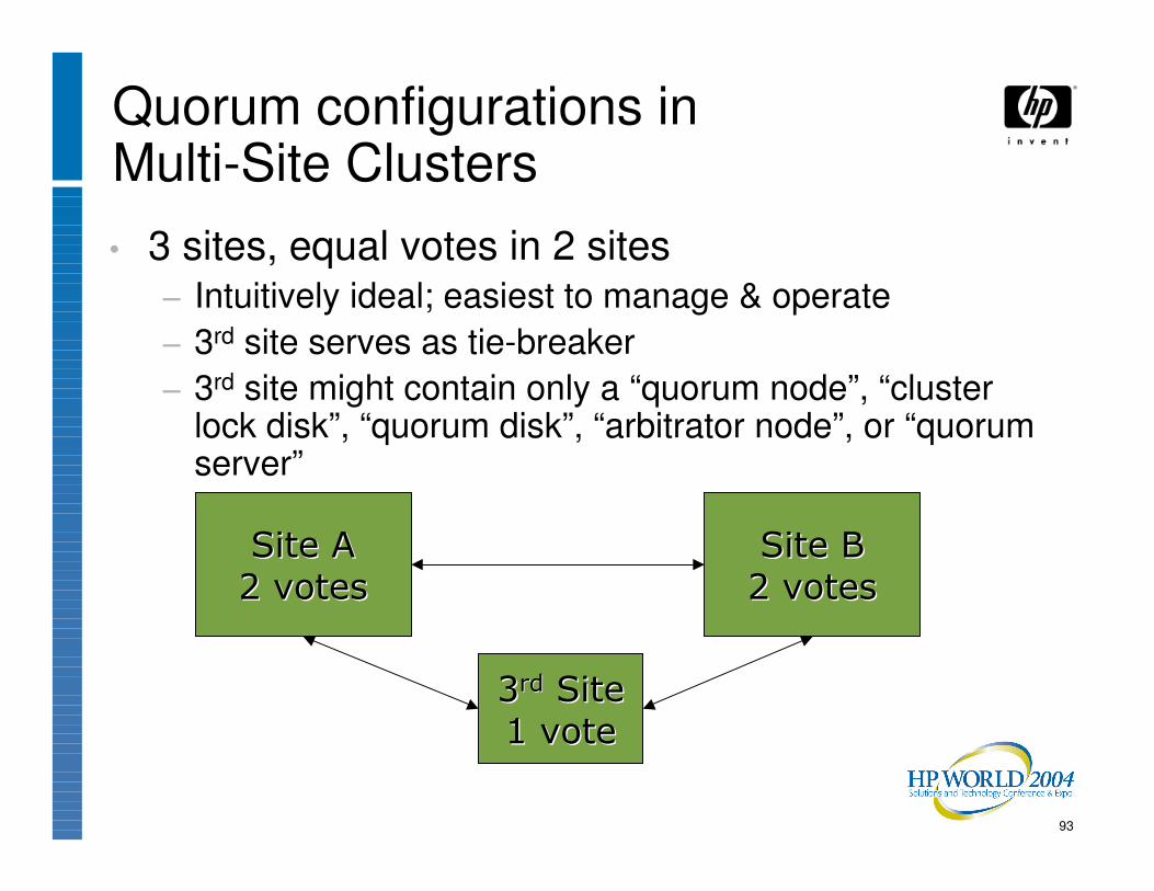
Quorum configurations inMulti-Site Clusters• 3 sites, equal votes in 2 sites
− Intuitively ideal; easiest to manage & operate− 3rd site serves as tie-breaker− 3rd site might contain only a “quorum node”, “cluster
lock disk”, “quorum disk”, “arbitrator node”, or “quorum server”
���� ����
(����(���� ���� ����
(����(����
))���� �� ��
!����!����
94
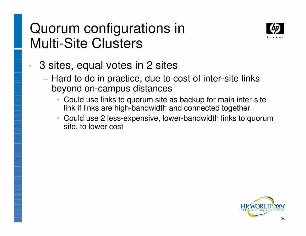
Quorum configurations inMulti-Site Clusters• 3 sites, equal votes in 2 sites
− Hard to do in practice, due to cost of inter-site links beyond on-campus distances
• Could use links to quorum site as backup for main inter-site link if links are high-bandwidth and connected together
• Could use 2 less-expensive, lower-bandwidth links to quorum site, to lower cost

95
Quorum configurations in3-Site Clusters
B
BB
BB
B
BN N
N N
NN
DS3, Gbe, FC, ATM 10 megabit

96
Quorum configurations inMulti-Site Clusters• 2 sites:
− Most common & most problematic:• How do you arrange votes? Balanced? Unbalanced?
− Note: Some quorum schemes don’t allow unbalanced votes
• If votes are balanced, how do you recover from loss of quorum which will result when either site or the inter-site link fails?
���� ���� ���� ����
97
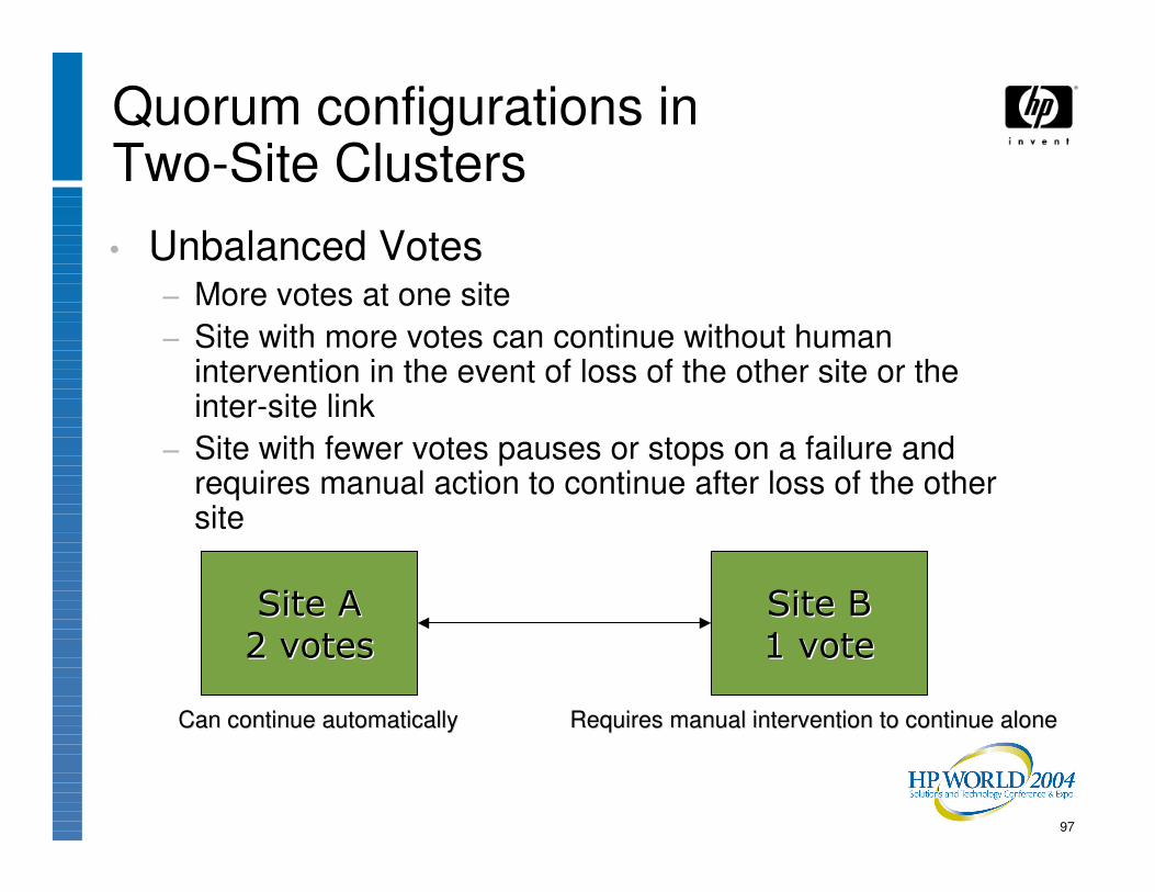
Quorum configurations inTwo-Site Clusters• Unbalanced Votes
− More votes at one site− Site with more votes can continue without human
intervention in the event of loss of the other site or the inter-site link
− Site with fewer votes pauses or stops on a failure and requires manual action to continue after loss of the other site
���� ����
(����(���� ���� ����
!����!����
Can continue automaticallyCan continue automatically Requires manual intervention to continue aloneRequires manual intervention to continue alone

98
Quorum configurations inTwo-Site Clusters• Unbalanced Votes
− Very common in remote-mirroring-only clusters (not fully disaster-tolerant), where one site is considered Primary and the other as Backup or Standby
− Common mistake: give more votes to Primary site, but leave Standby site unmanned
• Problem: Cluster can’t run without the Primary site up, or humanintervention at the (unmanned) Standby site
�������� ���������� ��
(����(����
*�����*�����
������ �� ������ ��
!����!����
+�������+�������
Can continue automaticallyCan continue automatically Requires manual intervention to continue aloneRequires manual intervention to continue alone
%�&�%�&�������
99
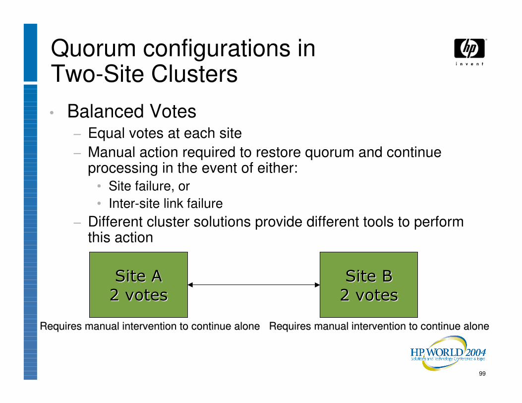
Quorum configurations inTwo-Site Clusters• Balanced Votes
− Equal votes at each site− Manual action required to restore quorum and continue
processing in the event of either:• Site failure, or• Inter-site link failure
− Different cluster solutions provide different tools to perform this action
���� ����
(����(���� ���� ����
(����(����
Requires manual intervention to continue aloneRequires manual intervention to continue aloneRequires manual intervention to continue aloneRequires manual intervention to continue alone

100
Data Protection Scenarios• Protection of the data is extremely important in a
disaster-tolerant cluster
• We’ll look at two relatively obscure but dangerous scenarios that could result in data loss:− “Creeping Doom”− “Rolling Disaster”

101
“Creeping Doom” Scenario
Inter-site link
*������*������

102
“Creeping Doom” Scenario
Inter-site link
*������*������
����&����&�������������&����&���������
�����,��������#������,��������#�
����&����-�����./��������&����-�����./����
�����������������-/0�������-/0
103
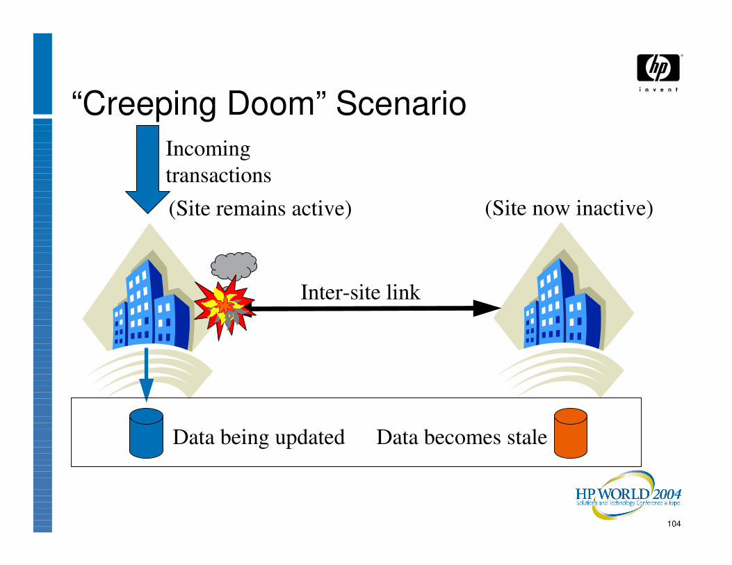
“Creeping Doom” Scenario• First symptom is failure of link(s) between two
sites− Forces choice of which datacenter of the two will
continue
• Transactions then continue to be processed at chosen datacenter, updating the data
104
“Creeping Doom” Scenario
Inter-site link
(Site now inactive)
Data becomes staleData being updated
Incoming transactions(Site remains active)

105
“Creeping Doom” Scenario• In this scenario, the same failure which caused
the inter-site link(s) to go down expands to destroy the entire datacenter

106
“Creeping Doom” Scenario
Inter-site link
Stale dataData with updates is destroyed

107
“Creeping Doom” Scenario• Transactions processed after “wrong” datacenter
choice are thus lost− Commitments implied to customers by those
transactions are also lost

108
“Creeping Doom” Scenario• Techniques for avoiding data loss due to
“Creeping Doom”:− Tie-breaker at 3rd site helps in many (but not all)
cases− 3rd copy of data at 3rd site

109
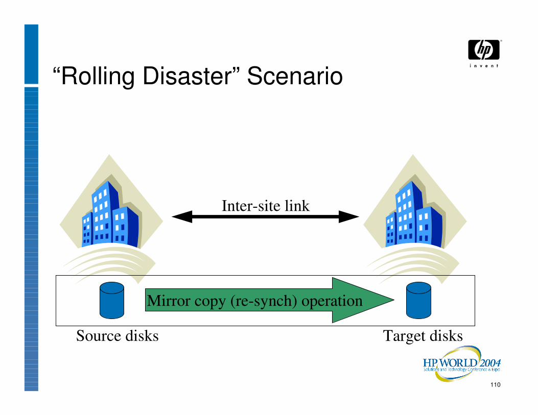
“Rolling Disaster” Scenario• Problem or scheduled outage makes one site’s
data out-of-date
• While doing a resynchronization operation to update the disks at the formerly-down site, a disaster takes out the primary site
110
“Rolling Disaster” Scenario
Inter-site link
Target disksSource disks
Mirror copy (re-synch) operation

111
“Rolling Disaster” Scenario
Inter-site link
Partially-updated disksSource disks destroyed
Re-synch operation interrupted

112
“Rolling Disaster” Scenario• Techniques for avoiding data loss due to “Rolling
Disaster”:− Keep copy (backup, snapshot, clone) of out-of-date
copy at target site instead of over-writing the only copy there, or,
− Use a data replication solution which keeps writes in order during re-synchronization operations
• Either way, the surviving data copy will be out-of-date, but at least you’ll have a readable copy of the data
− Keep a 3rd copy of data at a 3rd site

113
Long-distance Cluster Issues• Latency due to speed of light becomes
significant at higher distances. Rules of thumb:− About 1 ms per 100 miles, one-way− About 1 ms per 50 miles round-trip latency
• Actual circuit path length can be longer than highway mileage between sites
• Latency can adversely affect performance of− Remote I/O operations− Remote locking operations

114
200 240 400
4400
0500
100015002000250030003500400045005000
Latency (micro-seconds)
Gigabit Ethernet,zero distanceFast Ethernet, zerodistanceATM 15 miles
DS-3 250 miles
Lock Request Latencies
115
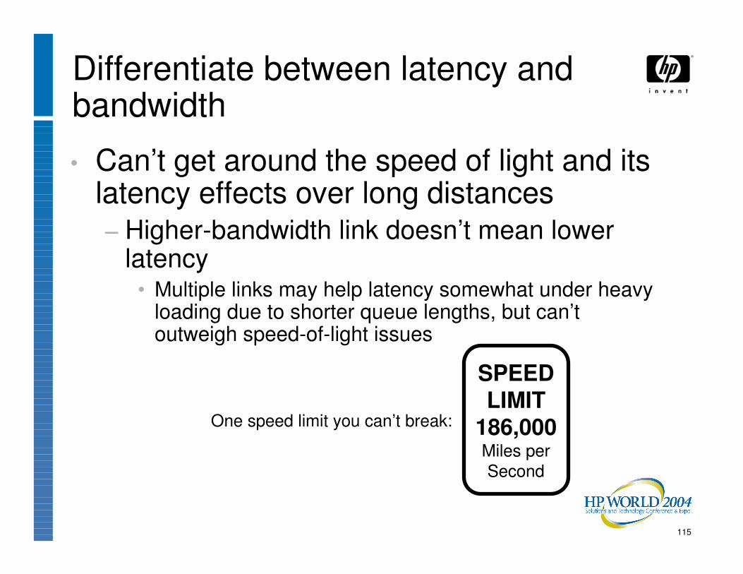
• Can’t get around the speed of light and its latency effects over long distances− Higher-bandwidth link doesn’t mean lower
latency• Multiple links may help latency somewhat under heavy
loading due to shorter queue lengths, but can’t outweigh speed-of-light issues
Differentiate between latency and bandwidth
SPEEDLIMIT
186,000Miles perSecond
One speed limit you can’t break:

116
Application Schemes in 2-site Clusters1. Hot Primary / Cold Standby
2. Hot / Hot, but Alternate Workloads
3. Uniform Workload Across Sites
117
Application Scheme 1:Hot Primary/Cold Standby• All applications normally run at the primary site
− Second site is idle, except for data replication, until primary site fails, then it takes over processing
• Performance will be good (all-local locking)
• Fail-over time will be poor, and risk high (standby systems not active and thus not being tested)
• Wastes computing capacity at the remote site
118
Application Scheme 2:Hot/Hot but Alternate Workloads• All applications normally run at one site or the
other, but not both; data is shadowed between sites, and the opposite site takes over upon a failure
• Performance will be good (all-local locking)
• Fail-over time will be poor, and risk moderate (standby systems in use, but specific applications not active and thus not being tested from that site)
• Second site’s computing capacity is actively used

119
Application Scheme 3:Uniform Workload Across Sites• All applications normally run at both sites
simultaneously; surviving site takes all load upon failure
• Performance may be impacted (some remote locking) if inter-site distance is large
• Fail-over time will be excellent, and risk low (standby systems are already in use running the same applications, thus constantly being tested)
• Both sites’ computing capacity is actively used

120
Capacity Considerations• When running workload at both sites, be careful
to watch utilization.
• Utilization over 35% will result in utilization over 70% if one site is lost
• Utilization over 50% will mean there is no possible way one surviving site can handle all the workload

121
Response time vs. Utilization
0
5
10
15
20
0 10 20 30 40 50 60 70 80 90 100
Utilization (%)
Resp
onse
Tim
e
“Knee” of the curve

122
Response time vs. Utilization: Impact of losing 1 site
0
5
10
15
20
0 10 20 30 40 50 60 70 80 90 100
Utilization (%)
Resp
onse
Tim
e

123
Testing• Separate test environment is very helpful, and
highly recommended
• Good practices require periodic testing of a simulated disaster. Allows you to:− Validate your procedures− Train your people

Real-Life Examples
125
Real-Life Examples:Credit Lyonnais•Credit Lyonnais fire in Paris, May 1996
•Data replication to a remote site saved the data
•Fire occurred over a weekend, and DR site plus quick procurement of replacement hardware allowed bank to reopen on Monday

“ In any disaster, the key is to protect the data. If you lose your CPUs, you can replace them. If you lose your network, you can rebuild it. If you lose your data, you are down for several months. In the capital markets, that means you are dead. During the fire at our headquarters, the DIGITAL VMS Clusters were very effective at protecting the data.”
Jordan DoePatrick Hummel
IT Director, Capital Markets Division, Credit Lyonnais
127
Real-Life Examples:Online Stock Brokerage• 2 a.m. on 29 December, 1999, an active stock
market trading day
• Just 3 days before Y2K− Media were watching like hawks to detect any system
outages that might be related to inadequate Y2K preparation
− Customers fearing inadequate Y2K preparation would likely pull their money out in a hurry
• UPS Audio Alert alarmed security guard on his first day on the job, who pressed emergency power-off switch, taking down the entire datacenter
128
Real-Life Examples:Online Stock Brokerage• Disaster-tolerant cluster continued to run at
opposite site; no disruption
• Ran through that trading day on one site alone
• Performed shadow copies to restore data redundancy in the evening after trading hours
• Procured a replacement for the failed security guard by the next day

129
Real-Life Examples: Commerzbank on 9/11• Datacenter near WTC towers• Generators took over after power failure, but dust
& debris eventually caused A/C units to fail• Data replicated to remote site 30 miles away• One AlphaServer continued to run despite 104°F
temperatures, running off the copy of the data at the opposite site after the local disk drives had succumbed to the heat
• See http://h71000.www7.hp.com/openvms/brochures/commerzbank/
130
Real-Life Examples: Online Brokerage• Dual inter-site links from different vendors
• Both used fiber optic cables across the same highway bridge− El Niño caused flood which washed out bridge
• Vendors’ SONET rings wrapped around the failure, but latency skyrocketed and cluster performance suffered

131
Business Continuity: Not Just IT•The goal of Business Continuity is the ability for the entire business, not just IT, to continue operating despite a disaster.
•Not just computers and data:− People− Facilities− Communications: Data networks and voice− Transportation− Supply chain, distribution channels− etc.

132
Business Continuity Resources• Disaster Recovery Journal:
− http://www.drj.com/
• Contingency Planning & Management Magazine− http://www.contingencyplanning.com/
• Continuity Insights magazine− http://www.continuityinsights.com/
• Forbes Calamity Prevention− http://www.calamityprevention.com/
• The Uptime Institute− http://upsite.com/
• DRJ and CPM both hold conferences as well

133
Speaker Contact Info:
•Keith Parris
•E-mail: [email protected]
•Web: http://www2.openvms.org/kparris/
and http://www.geocities.com/keithparris/


Co-produced by:
Recommended

![Title Fault-Tolerant Quantum Computation on Logical Cluster ......quantum computation under imperfect gate operations, namely fault-tolerant quantum computation [11, 12]. The main](https://img.dokumen.tips/doc/110x75/60f3fd58ff2b1f2547000d7a/title-fault-tolerant-quantum-computation-on-logical-cluster-quantum-computation.jpg)