Digital Electronics
Flip-Flops & Latches
Flip-Flops & Latches
2
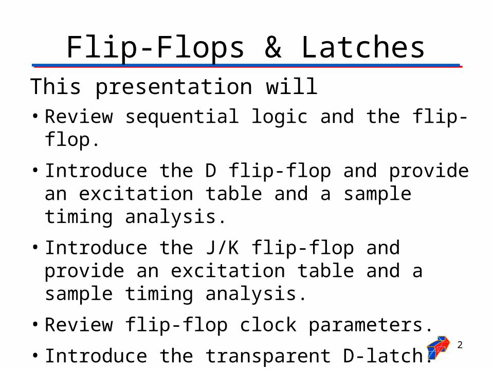
This presentation will• Review sequential logic and the flip-flop.
• Introduce the D flip-flop and provide an excitation table and a sample timing analysis.
• Introduce the J/K flip-flop and provide an excitation table and a sample timing analysis.
• Review flip-flop clock parameters.
• Introduce the transparent D-latch.
• Discuss flip-flop asynchronous inputs.
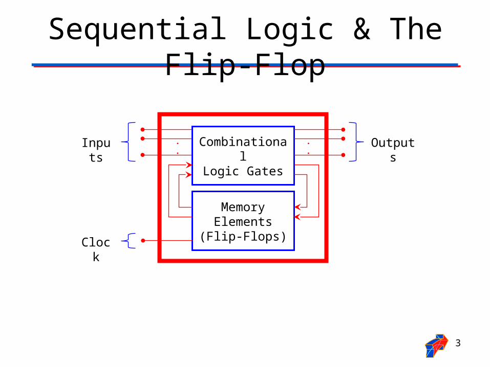
Sequential Logic & The Flip-Flop
3
CombinationalLogic Gates
.
.Inputs Outputs
Memory Elements
(Flip-Flops)
.
.
Clock

D Flip-Flop: Excitation Table
4
QCLK
D Q
D CLK
0 0 1
1 1 0
: Rising Edge of Clock
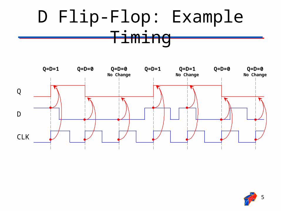
D Flip-Flop: Example Timing
5
Q
D
CLK
Q=D=1 Q=D=1Q=D=0 Q=D=1No Change
Q=D=0No Change
Q=D=0No Change
Q=D=0
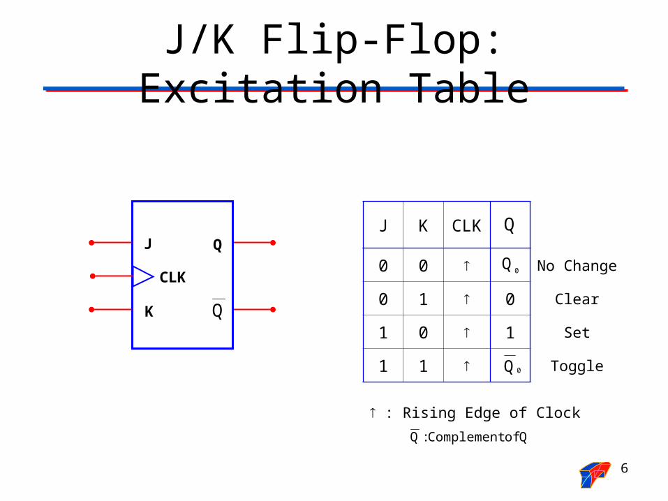
J/K Flip-Flop: Excitation Table
6
J K CLK
0 0 No Change
0 1 0 Clear
1 0 1 Set
1 1 Toggle
: Rising Edge of Clock
Q of Complement: Q
Q
QK
J Q
CLK
0Q
0Q
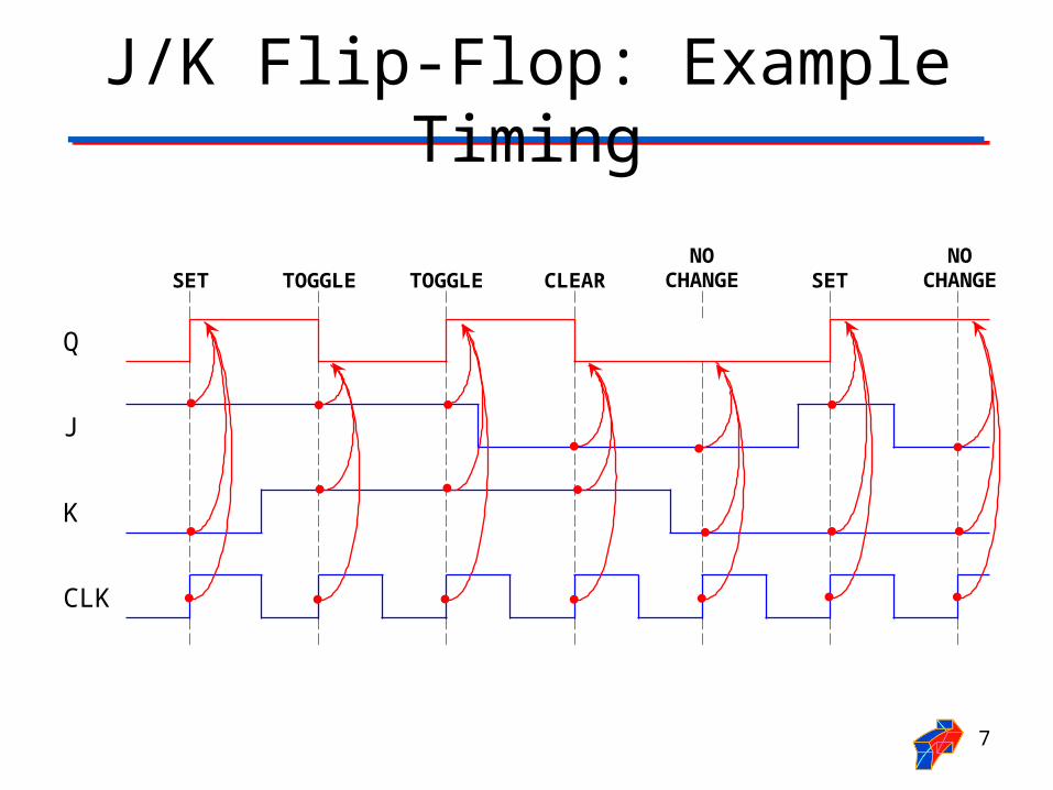
J/K Flip-Flop: Example Timing
7
Q
J
K
CLK
SET CLEARTOGGLENO
CHANGETOGGLENO
CHANGESET

Clock Edges
8
1
0
1
0
Positive Edge Transition
Negative Edge Transition

POS & NEG Edge Triggered D
9
QCLK
D Q
D CLK
0 0 1
1 1 0
: Rising Edge of Clock
D CLK
0 0 1
1 1 0
: Falling Edge of Clock
QCLK
D Q
Positive Edge Trigger
Negative Edge Trigger
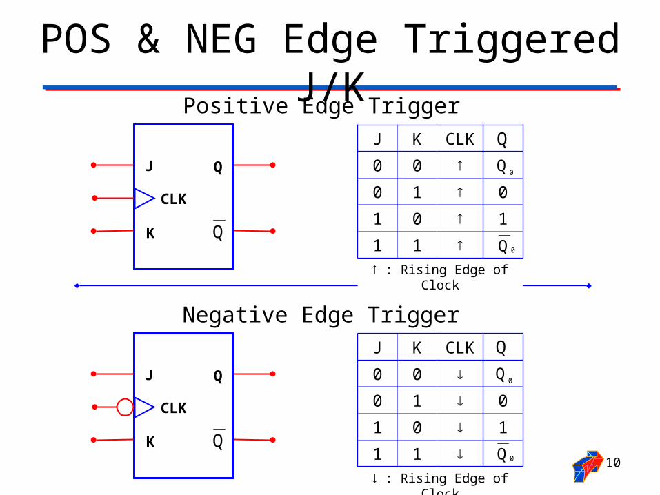
POS & NEG Edge Triggered J/K
10
Positive Edge Trigger
Negative Edge Trigger
QK
J Q
CLK
QK
J Q
CLK
J K CLK
0 0
0 1 0
1 0 1
1 1
: Rising Edge of Clock
Q
0Q
0Q
J K CLK
0 0
0 1 0
1 0 1
1 1
: Rising Edge of Clock
Q
0Q
0Q

Flip-Flop Timing
11
Data Input(D,J, or K)
1
0
tS
Setup Time
tH
Hold TimePositive
EdgeClock
1
0
Setup Time (tS): The time interval before the active transition of the clock signal during which the data input (D, J, or K) must be maintained.
Hold Time (tH): The time interval after the active transition of the clock signal during which the data input (D, J, or K) must be maintained.
12
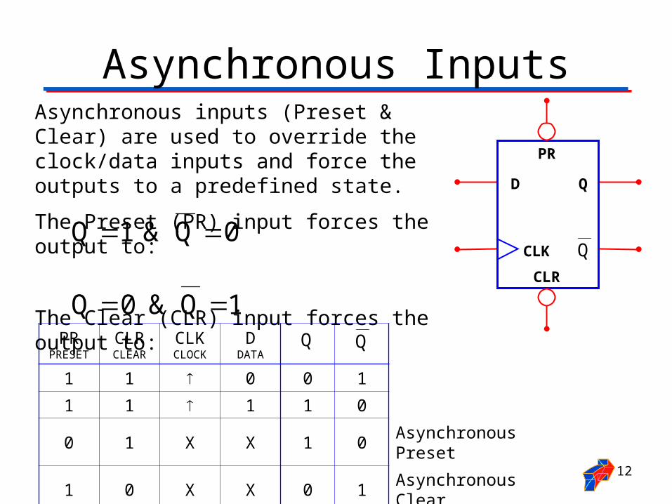
PRPRESET
CLRCLEAR
CLKCLOCK
DDATA
1 1 0 0 1
1 1 1 1 0
0 1 X X 1 0 Asynchronous Preset
1 0 X X 0 1 Asynchronous Clear
0 0 X X 1 1 ILLEGAL CONDITION
QCLK
D Q
PR
CLR
Asynchronous Inputs
Asynchronous inputs (Preset & Clear) are used to override the clock/data inputs and force the outputs to a predefined state.
The Preset (PR) input forces the output to:
The Clear (CLR) input forces the output to:
0Q & 1Q
1Q & 0Q
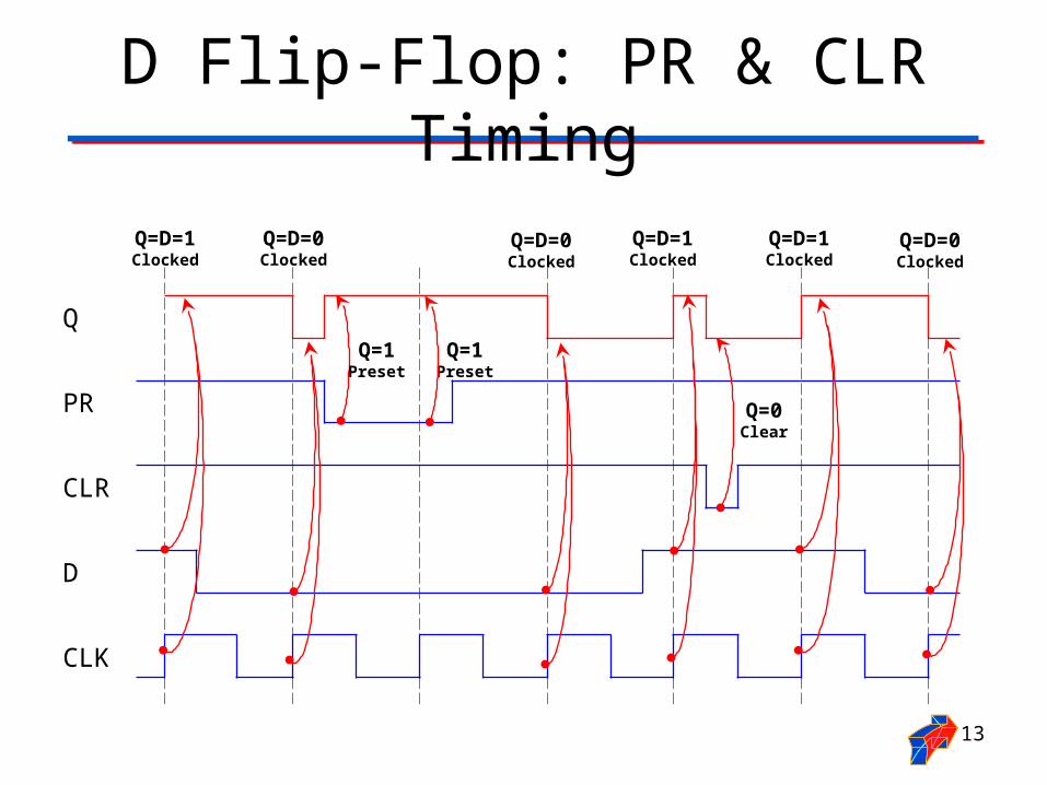
D Flip-Flop: PR & CLR Timing
13
Q
PR
CLR
D
CLK
Q=1Preset
Q=D=0Clocked
Q=D=0Clocked
Q=1Preset
Q=D=0Clocked
Q=0Clear
Q=D=1Clocked
Q=D=1Clocked
Q=D=1Clocked

Transparent D-Latch
14
QEN
D Q
EN D
0 X
1 0 0 1
1 1 1 0
0Q0Q
EN: Enable

Transparent D-Latch: Example Timing
15
Q
D
EN
“Latched”Q=0
“Latched”Q=1
“Latched”Q=0
“Transparent”Q=D
“Transparent”Q=D
“Transparent”Q=D

Flip-Flop Vs. Latch• The primary difference between a D flip-flop and
D latch is the EN/CLOCK input.
• The flip-flop’s CLOCK input is edge sensitive, meaning the flip-flop’s output changes on the edge (rising or falling) of the CLOCK input.
• The latch’s EN input is level sensitive, meaning the latch’s output changes on the level (high or low) of the EN input.
16
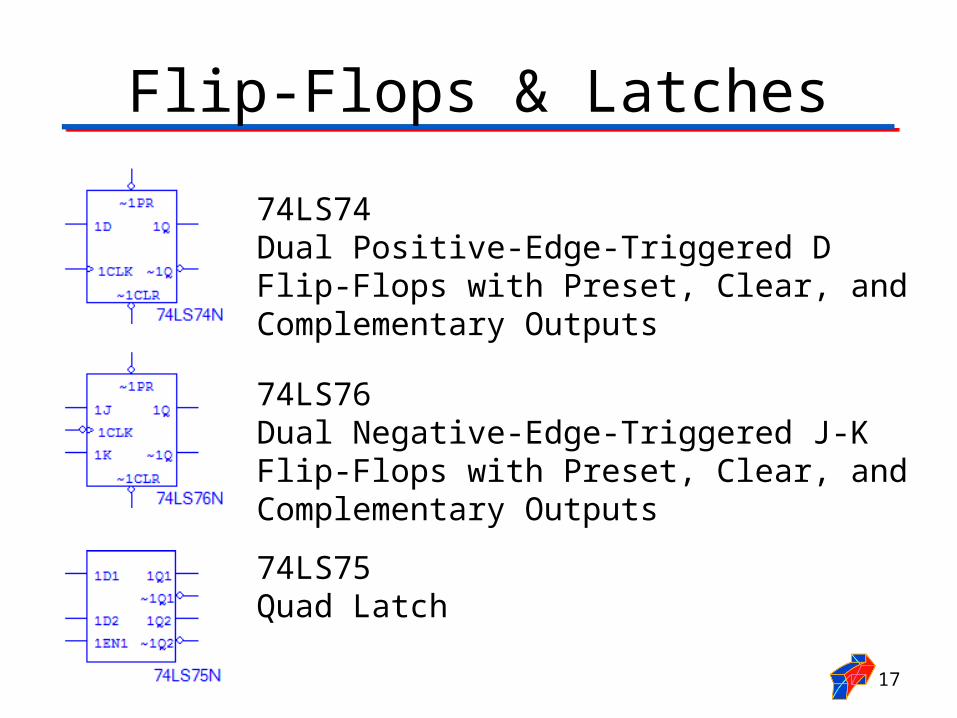
Flip-Flops & Latches
17
74LS74 Dual Positive-Edge-Triggered D Flip-Flops with Preset, Clear, and Complementary Outputs
74LS76 Dual Negative-Edge-Triggered J-K Flip-Flops with Preset, Clear, and Complementary Outputs
74LS75 Quad Latch
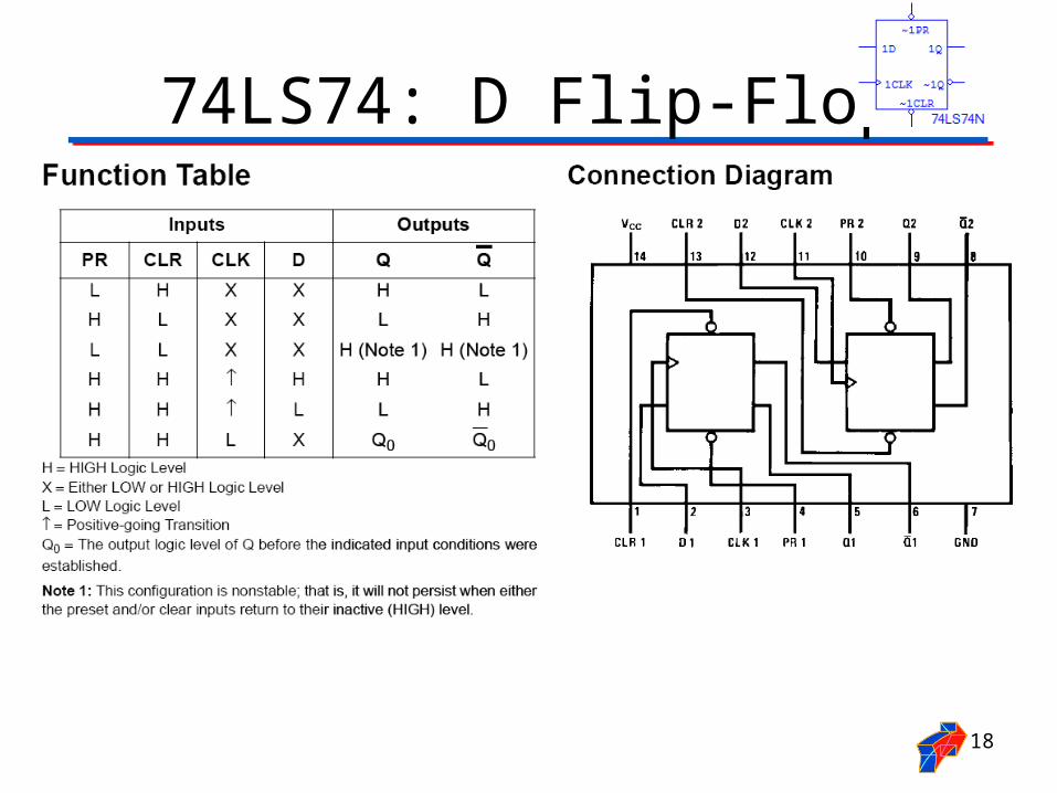
74LS74: D Flip-Flop
18

74LS76: J/K Flip-Flop
19
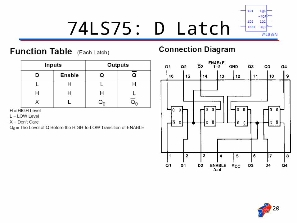
74LS75: D Latch
20
Recommended