Development of Ultra-low Platinum Alloy C th d C t l t f PEM F l C ll Cathode Catalyst for PEM Fuel Cells
2010 DOE Hydrogen Program Fuel Cell Project Kick-Off
P I : Branko N Popov P. I.: Branko N. Popov
Center for Electrochemical Engineering
University of South Carolina
Columbia SC 29208. September 28, 2010
This presentation does not contain any proprietary, confidential, or otherwise restricted information
Center for Electrochemical Engineering, University of South Carolina 1

Overview
Timeline • SStart ddate: JJune 01 2010 01 2010 • End date: Nov 30 2012 (Phase I)
: May 31 2014 (Phase II)
Budget • Total project funding
¾ DOE share: $ 4 400 000 ¾ DOE share: $ 4,400,000 ¾ Contractor share: $1,100,000
• Incremental funding received in FY10: $750,000$750,000
• Funding for FY11: $1,100,000
Barriers • Catalyst cost • Catalyst performance Catalyst performance • Catalyst Durability
Targets •• PGM loading of 0 2 mg/cm2 PGM loading of 0.2 mg/cm • Mass activity of 0.44 A/mgPt at 0.9 V
(Year 2015). • Specific activity of 720 µA/cm2 at 0 9 at 0.9• Specific activity of 720 µA/cm2
V (Year 2015). • Electrochemical surface area loss <40% • Cycling performance for 5000 h at ≤ 80 oCCCycling performance for 5000 h at ≤ 80
and 5000 h at > 80 oC
Partners •• Hyundai Motor Company S Korea Hyundai Motor Company, S. Korea • Yonsei University, S. Korea
Center for Electrochemical Engineering, University of South Carolina 2

Problem Definition – In Developing Low Loading Platinum Catalysts
• C l PCatalyst Perfformance ¾ Platinum and catalyst support ratio ¾ Catalyst agglomeration during alloying process ¾ Pt dissolution and agglomeration ¾ Increase of inter-pparticle resistance and dis-bondingg of catalyyst pparticles duringg the leachingg
process ¾ Loss of electrochemical surface area ¾ Alloying metal dissolution and incorporation in to the membrane ¾ Catalyst-ionomer interaction ¾¾ Catalyst layer properties – thickness porosity and porethickness, porosity and pore-size distribution andCatalyst layer properties size distribution and
hydrophilic/hydrophobic properties. • Catalyst Support Stability
¾ Water content. ¾ Low pH (< 1). ¾ High temperature (50 – 90 °C). ¾ High oxygen concentration. ¾ Carbon corrosion at high potentials (Increases between 1.2 and 1.5 V during start-up and shut
down cycles in automotive application) 9 C + 2H22O → CO22 + 4H+ + 4e- E0 = 0.118 V vs. RHE at 25 oC
• Carbon oxidation results in: ¾ Increase in the hydrophilic properties and affects the water removal leading to increased mass
transport losses. ¾ Decreases the thickness of the catalyst layers which increases the cell resistance. ¾¾ Pt catalyst accelerates the rate of carbon corrosionPt catalyst accelerates the rate of carbon corrosion.
Center for Electrochemical EngineerCenter for Electrochemical Engineering,ing, UniversityUniversity of Southof South CarolinaCarolina 33

9
-
Project Objectives
• Ultra-low loading Pt catalyysts for oxygen reduction reaction with higgh activityy and ggoodg yg stability will be developed through: ¾ Synthesis of hybrid cathode catalyst (HCC) consisting of carbon composite catalyst (CCC)
developed at USC as support and activated platinum with high electrochemical surface area. Platinum catalyst activation will be performed using USC developed leaching procedure for Pt-Co,Platinum catalyst activation will be performed using USC developed leaching procedure for Pt Co, Pt-Ni and Pt-Cu alloys.
¾ Synthesis of activated low loading platinum catalysts with high electrochemical surface area using: 9 Stable conductive TiO2 based supports synthesized by template assisted procedure developed at
USC. 9 Stable and electrochemically active CCC-TiO2 hybrid support with pyridinic active sites for ORR.
¾ Synthesis of leached Pt-Ni alloy catalysts with high electrochemical surface area Pt deposited on activated graphitic carbon developed at HMC.
¾ Synthesis of leached Pt-Cu catalysts with high electrochemical surface area Pt deposited on ¾ Synthesis of leached Pt Cu catalysts with high electrochemical surface area Pt deposited on activated carbon developed at Yonsei University.
� Facile scale-up synthesis procedure for the production of all the suggested catalysts. ¾ Elimination of Pt-alloy particle agglomeration during annealing process at high temperature
usiing a proceddure ddevellopedd at Y t Yonseii U Uniiversitit y. ¾ Decreasing the inter-particle resistance and prevent the catalyst particle detachment from
the support through: 9 Introduction of a thin interlayer of Pt or Pd between the support and the catalyst 9 Optimization of Pt and alloying metal composition.
Center for Electrochemical Engineering, University of South Carolina 4

Project Objectives
¾ Synthesis of high distribution of Pt with high initial loading over carbon support without Pt loss Initial results (HR-TEM) at Yonsei University indicated that the Pt without Pt loss. Initial results (HR TEM) at Yonsei University indicated that the Pt particle size of 70 wt.% Pt/C is smaller than the commercial 40 wt.% Pt/C catalyst.
¾ Engineer membrane electrode assembly (MEA) with
9 hi l9 thin catallyst layer
9optimize the catalyst-catalyst support ratio
¾ Studyy the activit yy and durabilityy of different low loadingg Pt catalyysts in singgle cell (50 cm2) test conditions.
¾ Construct short-stack (50 cm2, up to 10 cells) containing ultra-low Pt loading catalyst and evaluate the pperformance under simulated automotive opperatingg conditions.
Center for Electrochemical Engineering, University of South Carolina 5

Previous Accomplishments at University of South Carolina
Development of Metal Free Catalyst

-
1
USC Strategy: HCC Catalyst
Strategy: Combine the catalytic activity of Pt at high potentials with that of carbon composite catalyst (CCC) at low potentials forming a hybrid cathode catalysts (HCC) having ultra low Pt loadinghaving ultra-low Pt loading.
Carbon modification
Carbon composite Catalyst
Hybrid cathode catalysts (HCC)
• Surface modification of carbon black with: (i) O-containing group
• “Metal-catalyzed pyrolysis” to increase the
• Pt deposition • Pyrolysis
(i) O containing group (ii) N-containing group
• Pyrolysis
increase the number of active sites by leaching
Pt-rich alloyPt rich alloy
Pt-alloyCo deposition Heat treatment followed bydeposition leaching
Center for Electrochemical Engineering, University of South Carolina
Co covered with a thin graphitic layer
1 32
on the surface Pt-alloy
32
7

-
Metal-Free Catalyst: Catalytic Activity and Selectivity C
uurre
nt /
mA
0
-0.2
-0.4
-0 60.6
-0.8
-1.0
MF-C oxidized carbon
TUF-C
*Te-N H 2
-C O -saturated H O
SeUF-C
UF-C
SOTe N H4
C 2 saturated H 42SO
0 0.2 0.4 0.6 0.8 1.0
Potential / V vs. RHE
Ni difi dNitrogen-modified carbon-based % H2O2 at 0.5 V
catalyst MF-C 28 TUF-C 17 UF-C 3
SeUF CSeUF-C 11
Te-N2H4-C 1
*Synthesis of Te-N2H4-C (1) Adsorption of telluric acid on carbon black (1) Adsorption of telluric acid on carbon black (2) Reduction by hydrazine (3) Pyrolysis at 1000 oC
HIGHLIGHT • The nitrogen-containing polymer modification methodology increases the onset potential for
oxygen reduction by ca. 400 mV, as compared with carbon black. • The nitrogen modified carbon-based catalyst catalyzes oxygen reduction to water
with low H2O2 production.
Popov et.al., J. Power Sources, 182 (2008) 18-23. Center for Electrochemical Engineering, University of South Carolina
8
P i A li h t t U i it f Previous Accomplishments at University of South Carolina
Development of Carbon Composite Catalyst

Synthesis of Carbon Composite Catalyst
HIGHLIGHT The exclusion of carbon black in the catalyst synthesis can increase nitrogen content in theresultingresulting catalystscatalysts, hence,hence increases the density of ORR active sites.
Popov et.al., Electrochim. Acta. 55 (2010) 2853-2858.
iR C
orre
cted
Pot
entia
l (V)
0.8
0 4
0.6
0.2
0.4
0.0 0.00 0.25 0.50 0.75 1.00 1.25 1.50
Current Density (A/cm2)
HIGHLIGHT Iron has the ability to alloy with carbon and nitrogen
d t 800 oC th t ti f i ti l liand at 800 oC the saturation of iron particles relives by the precipitation of carbon and nitrogen. (S. Maldonaldo and K. J. Stevenson , J. Phys. Chem. B, 109 (2005) 4707).
• Anode: E-TEK 20% Pt/C (0.4 mg cm-2 Pt) • Cathode: 2 mg cm-2 of carbon composite catalyst • Membrane: NafionTM 112
O ti t t 77 oC (H ) 75 oC (O ) 75 oC ( ll)• Operating temperature: 77 oC (H2); 75 oC (O2); 75 oC (cell)
Center for Electrochemical EngineerCenter for Electrochemical Engineering,ing, UniversityUniversity of Southof South CarolinaCarolina 1010

Nano-fiber
Active Sites: TEM and XPS
Metal atom Metal atom
* , carbon black o, Co x, Co, Fe, or Co-Fe ar
y un
it
* +, Fe3C
x+
x
nten
sity
/ ar
bitra
o
x
Rel
ativ
e In
HIGHLIGHTHIGHLIGHT • Metal atoms are covered with several graphitic
layers. • Nanostructured fiber of graphitic carbon was
formed as a result of metal-catalyzed pyrolysis. • No metal traces were detected on the surface of
carbon-based composite catalyst.
10 20 30 40 50 60 70 80
Scanning Angle, 2θ / degrees
HIGHLIGHT • In carbon composite catalyst, metals and
cementite (Fe3C) species are present inside the
carbon particles. • No metallic element on the surface was
detected by XPS.
Center for Electrochemical Engineering, University of South Carolina 11
Previous Accomplishments at University of South CarolinaCarolina
Development of Low Pt Loading Cathode CatalystDevelopment of Low Pt Loading Cathode Catalyst

0.8
0.6
Stability of USC HCC in Fuel Cell
1.01 0 Fresh Fresh After test After test
iR C
orre
cted
Cel
l Poot
entia
l / V
initial after 400 h
0 0.5 1.0 1.5 2.0 2.5
Intte
nsity
/ co
untss
s-1
300
250
200 200
150
100
anod
e
mem
bran
e
cath
ode
Ano
de
mem
bran
e
cath
ode
PtPt Pt Pt
Co Co50
0
Current Density / A cm-2
• Cathode: 0.4 mg cm-2 Pt-Co • Anode: 0.5 mg cm-2 ETEK Pt • Membrane: Nafion 112 G
DL
embr
ane
t (Pt
/C)
No dissolution of Co from the catalyst and diffusion into the membrane after 400 h of continuous operation.
y
• Membrane: Nafion 112 • Operating conditions: (i) H2/O2 (ii) no back pressure (iii) 77/75 oC
Cat
hode
G
USC
HC
C
ectr
olyt
e m
e
Ano
de c
atal
yst operation.
(iii) 77/75 oC ElA
Center for Electrochemical Engineering, University of South Carolina 13

0.8
1.0
0.4
0.6
0.2
Comparison of Catalytic Activity: Fuel Cell Studies C
eell P
oten
tial /
VV
25 0.04 mg Pt cm -2
iR un-corrected data
HCC
H2/O2, 75 oC No back pressure
Pt/C HCC
0 0.5 1.0 1.5 2.0 2.5
20
Freqq
uenc
y / %%
15
10
5
00 1 2 3 4 5 6
Current Density / A cm-2
Particle Size / nm
HIGHLIGHT • CCC is highly active for oxygen reduction, TEM: The USC HCC catalyst shows more
while carbon black is inactive. uniform dispersion of particles over the active • The catalytic performance of HCC is higher support with small average particle size and
narrower distribution. than Pt/C according to both RDE and fuel cell test.
Center for Electrochemical Engineering, University of South Carolina 14

Effect of Pt Loading on Catalytic Activity: Fuel Cell Studyy
at 0.7 V (b)
HCC
iR un-corrected data
Pt/C
HCCat 0.7 V (a)
Pt/C
iR un-corrected data
201.0
CCur
rent
Den
sity
/ A
cm-2
MMas
s Ac
tivity
/ A m
g-1 P
t
15
10
5
0.8
0.6
0.4
00.2 0.0 0.1 0.2 0.3 0.4 0.0 0.1 0.2 0.3 0.4
Pt Loading / mg cm-2 Pt Loadingg / mgg cm-2
HIGHLIGHT • The mass activity of HCC shows a 150% enhancement when Pt loading is
decreased from 0 1 to 0 04 mg cm-2 duedue toto thethe contributioncontribution from from thethe supportsupport atatdecreased from 0.1 to 0.04 mg cm 2
ultra-low Pt loading.
Center for Electrochemical Engineering, University of South Carolina 15

Previous Accomplishments at University of South Carolina
Development of TiO2 Supported Pt Catalyst

a d t a o d t o t eat e t to o
USC Strategy: Pt/TiO2 Catalyst
Strategy: Modification of titanium dioxide support for the facile deposition of Pt and Ptalloy catalysts.
TiO2 surface modification
Pt and Pt-alloy deposition
Catalyst activation modification deposition
• Surface modification • Surfactant assisted Pt • De-alloying and Heat-using developedusing USC developed USC and Pt-alloyy deposeposition treatment to form higgh methodology. for uniform particle surface area Pt and Pt
distribution. alloy catalyst.
Popov et.al., J. Am. Chem. Soc., 131 (2009) 13898-13899 Popov et.al., Appl. Catal. B: Environmental, 96 (2010) 224-231
Center for Electrochemical Engineering, University of South Carolina 17

Characterization – TiO2 and Pt/TiO2
0.03
m -1
TiO2 Pt/TiO2Surface area = 250 m2 g-1;
Average pore diameter = 4.2 nm
BET analysis
0.01
0.02
dV/d
D /
mL
g-1 nm
0.00
1 2 3 4 5 6 7 8 Pore diameter / nm
ty
20%Pt/TiO2
40%Pt/TiO2
60%Pt/TiO2
Inte
nsit
dPt = 3.4 nm
dPt = 4.1 nm
dPt = 4.8 nm
• Surface area of TiO2 = 250 m2 g-1. •• Pt particles with d = 3 5 werePt particles with dPt = 3-5 nmnm were
deposited on TiO2. • Pt particle size can be optimized by
controlling the nucleation rate.
30 40 50 60 70 80 2θ
18 Center for Electrochemical Engineering, University of South Carolina

Optimization Studies on Pt/TiO2 Catalysts: LSV
0.5
0.0
0 5 -0.5
-1.0
-1.5
-2.0
-2.5
-3.0
-3.5
-4.0 0.3 0.4 0.5 0.6 0.7 0.8 0.9 1
0.5 M H2SO4 Scan rate: 5 mV s-1
Pt loading: 100 µg cm-2
900 rpm 900 rpm
Potential / V vs. RHE TiO2
TiO2 (activated)TiO2 (activated) Pt/TiO2 (Conventional Procedure ) Pt/TiO2 (USC Preparation) PtPd/TiO2 (USC Preparation)
Conventional procedure for Pt deposition
Pt particle size is ~20 nm
USC deposition procedure USC deposition procedure
Cur
rent
deen
sity
/ m
A c
mm-2
5 nm
10 nm
Pt particle size is 3 – 6 nm
Pt and PtPd nanoparticles (3-6 nm) can be deposited on to TiO2 supports using USC developed procedure.
Center for Electrochemical Engineering, University of South Carolina 19

Accelerated Durability Test of Different Catalysts – CV Cycling between 0.6 and 1.4 V (Fuel Cell)
11
Pt/TiO2
0 l0 cycle
2000 cycle
4000 cycle
Pt/C
0 l0 cycle
1000 cycle
2000 cycle
0.9 0.9
IR fr
eee c
ell v
olta
ge /
V
IR fr
eee c
ell v
olta
ge / V0 80.8
0.7
0.6
0.5
0.4
0 80.8
0.7
0.6
0.5
0.4
0.3 0.3
0.2 00 0 3 0.6 0 9 1.2 1 5 1.8 2 1 00 0 3 00 6.6 0 9 1.2 1 5 1.8 2 1
0.2 0.3 0 6 0.9 1 2 1.5 1 8 2.1 0.3 0.9 1 2 1.5 1 8 2.1
Current density / A cm-2 Current density / A cm-2
IV curves were obtained after CV cycles. • Slight decrease in cell voltage (0.09 V) at 0 8 A cm-2 was observed after 4000at 0.8 A cm was observed after 4000
Membrane: Nafion® 112; Cell area: 25 cm2 cell. cycles for Pt/TiO2. Anode: 0.5 mg Pt cm-2 (E-TEK); Cathode: 0.4 mg Pt cm-2.
• Pt/C exhibited a large voltage drop Operating conditions: (i) H2/air; (ii) 25/25 psi; (iii) 80 °C. after 2000 cycles due to carbon Fl H 1 2/2 S i H idi 100% RHFlow rate H2/ i/air: 1.2/2 Stoichh; Humidity: 100% RH. corrosion and detachment and
agglomeration of catalyst particles.
Center for Electrochemical Engineering, University of South Carolina 20

t t t t t
2.3 µm
After
Cross-section Analysis of MEA with Pt/TiO2 and Pt/C Cathodes
Pt/TiO2 cathode
After • Pt/TiO2 electrode retained
a similar morphology and catalyst layer thickness (1 µm) before and after ADT.
7000 cycles
Initial state AftP /C Pt/C cathhodde I i i l After test
µ
After 2000 cycles
Center for Electrochemical Engineering, University of South Carolina
• Cracks were observed in the• Cracks were observed in the Pt/C cathode after ADT due to disintegration of the catalyst layer.
16.4 µm
21

-
Pt/TiO2
Pt/C (TKK)Tc = 80 h
Pt/TiO2
Pt/C (TKK)
Accelerated Corrosion Test of Pt/TiO2 and Pt/C Catalysts -Effect of Potential Holding at 1.2 V on Fuel Cell Performance
IR fr
ee c
eell v
olta
ge (VV
)
1
0.9
0.8
0.7
0.6
0.5
0.4
0.3
0.2 0.2 0 0.2 0.4 0.6 0.8 1 1.2
Current density (A/cm2)
Membrane: Nafion® 112. Anode: 0 5 mg Pt cm-2 (Pt/C E-TEK)Anode: 0.5 mg Pt cm (Pt/C, E TEK). Cathode: 0.4 mg cm-2 Pt catalysts. Operating conditions: (i) H2/air; (ii) 150 kPa; (iii) 80 °C; (iV) 25 cm2 cell; (v) flow rate H2/air: 3/3; (vi) humidity: 50% RH.
IV curves were obtained after potential holding experiment.
0 h 200 h
Normalized ECSA and potential loss at 0.5 A cm-2 as a function of corrosion time (Tc)
Tc = 80 h Pt/TiO2
Pt/C (TKK)
Pt/TiO2
Pt/C (TKK)
• Pt/C electrocatalyst showed a rapid decay (93%) in ECSA at Tc = 80 h.
• For Pt/TiO2 , total loss of ECSA is ~20% after Tc = 80 h. • No decrease in catalytic activity up to 200 h when
compared toto Pt/C (45% TKKTKK)) at 0.5 A cm-2 whencompared Pt/C (45%, at 0 5 A cm when polarized at 1.2 V.
Center for Electrochemical Engineering, University of South Carolina 22
-
/cm
1
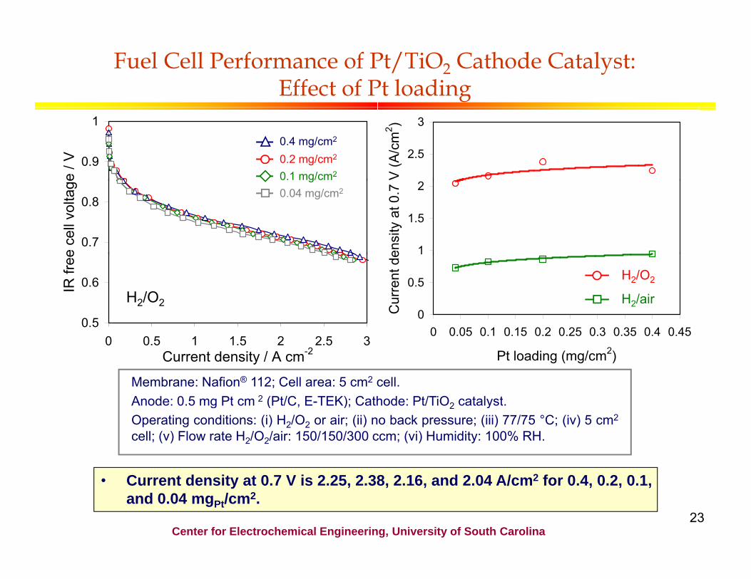
Fuel Cell Performance of Pt/TiO2 Cathode Catalyst: Effect of Pt loading
IR fr
eee c
ell v
olta
gee /
V
0.9
0.8
0.7
0.6
0.1 mg 2
0.4 mg/cm2
0.2 mg/cm2
V (A
/cm
2 )
g 0.04 mg/cm2
ensi
ty a
t 0.7
V
H2/O2 Cur
rent
de
0 0.5 1 1.5 2 2.5 3 Current density / A cm-2
Membrane: Nafion® 112; Cell area: 5 cm2 cell.
3
2.5
2
1.5
11
0.5
0
H2/O2
H2/air
0.5 0.5 0 0.05 0.1 0.15 0.2 0.25 0.3 0.35 0.4 0.45
Pt loading (mg/cm2)
Anode: 0 5 mg Pt cm-2 (Pt/C E TEK); Cathode: Pt/TiO catalystAnode: 0.5 mg Pt cm 2 (Pt/C, E-TEK); Cathode: Pt/TiO2 catalyst. Operating conditions: (i) H2/O2 or air; (ii) no back pressure; (iii) 77/75 °C; (iv) 5 cm2
cell; (v) Flow rate H2/O2/air: 150/150/300 ccm; (vi) Humidity: 100% RH.
• Current density at 0.7 V is 2.25, 2.38, 2.16, and 2.04 A/cm2 for 0.4, 0.2, 0.1, and 0.04 mgPt/cm2.
Center for Electrochemical Engineering, University of South Carolina 23
t
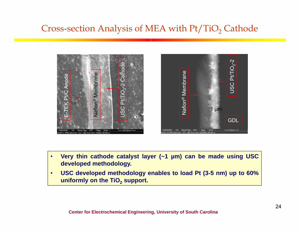
Cross-section Analysis of MEA with Pt/TiO2 Cathode
hode
Pt/C
Ano
de
t/TiO
2 -2
Cat
h
® M
embr
ane
E-T
EK
US
C P
Naf
ion®
e TiO
2 -2
n ® M
embr
ane
US
C P
t/T
Naf
ion
GDL
1 µm
• Veryy thin cathode catalyyst layyer ((~1 µm) can be made usingg USCµ ) developed methodology.
• USC developed methodology enables to load Pt (3-5 nm) up to 60% uniformly on the TiO2 support.
Center for Electrochemical Engineering, University of South Carolina 24
Summary (Previous Accomplishments)
USC HCC Catalyst � USC HCC catalyst shows higher performance than Pt/C at all loadings between 0.04 and 0.4 mg cm-2. � The mass activity of HCC shows a 150% enhancement when Pt loading is decreased from 0.1 to 0.04 mg cm-2 due to the contribution from the support (CCC) at ultra-low Pt loading.
Low Loading Leached Pt Catalyst (USC Developed TiO2 Support)
USC Pt/TiO C t lUSC Pt/TiO2 Catalystt � Slight decrease in cell voltage (0.09 V) at 0.8 A cm-2 was observed after 4000 cycles (cycling between 0.6 and 1.4 V) for Pt/TiO2. Pt/C exhibited a large voltage drop after 2000.
l d t b i d d t h t d l ti f t l t ti lcycles due to carbon corrosion and detachment and agglomeration of catalyst particles. � Pt/TiO2 do not show any decrease of fuel cell performance after 200 h DOE accelerated corrosion test. Pt/C electrocatalyst showed a rapid decay (93%) in ECSA after 80 h.
Center for Electrochemical Engineering, University of South Carolina 25

USC Approach and Future Work (Catalyst Synthesis Based on Leached Pt-alloy Catalysts Deposited on CCC, TiO2, Activated Graphitic Carbon
Supports)
Catalyst Synthesis (Task 1)
Low Loading of Pt-alloy Hybrid Cathode Catalysts (HCC) (Task 1 1)
Low Loading Pt Catalysts Deposited on USC Developed TiO2
e, f (Task 2) (Task 1.1) TiO2 (Task 2)
L L di f Pt C t l tLow Loading of Pt Catalysts Deposited on Catalytically Active USC Developed CCC a-d (Task 1.2.)
LLow LLoading of Pt f Pt L L di Pt L L di f Pt Low Loading of Pt Catalysts Deposited on CCC-TiO2 Hybrid Support*
(Task 1.3.)
di Low Loading Pt Catalysts Deposited Catalysts Deposited on on Activated Activated Carbon Graphitic Carbon (Yonsei Univ) g, h
((HMC) (Task 2.1) ((Task 2.2))) ( ) aa. Popo et al J P S 188 (2009) 38 Popov et.al., J Power Sources, 188 (2009) 38. b. Popov et.al., Appl. Catal. B: Environmental, 93 (2009) 156. c. Popov et.al., J Power Sources, 183 (2008) 34. d. Popov et.al. J. Power Sources, 157 (2006) 56. e. Popov et.al., Appl. Catal. B: Environmental, 96 (2010) 224. f. Popov et.al., J. Am. Chem. Soc., 131 (2009) 13898. g. Kim et.al., Electrochem. Commun., 11 (2009) 1131.
*Hybrid support made of carbon composite catalyst and metal oxide (TiO2)
h. Kim et.al., Electrochim. Acta, 54 (2009) 6515. 26 Center for Electrochemical Engineering, University of South Carolina

eo e ca a d
USC Approach and Future Work (Catalyst Performance Evaluation)
Theoretical and Structure property
Catalysts Developed at USC, HMC and Yonsei
(Task 1 and Task 2)
Electrochemical Studies (Task 3)
Structure-property Studies (Task 4)
Performance and D bilit St di (T k 5) Durability Studies (Task 5)
DOE Test Protocol for Catalyst Durability
DOE Test Protocol for Catalyst Support Durability
Selection of Best Performing Two Catalysts
Short stack Testing Short-stack Testing (Task 6)
Short stack Delivery to DOE Short-stack Delivery to DOE Designated Site
Center for Electrochemical Engineering, University of South Carolina 27

-
Proposed Future Work
• ObjectivesObjectives: To synthesize low cost : To synthesize low cost, high stability leached Pt catalysts with high• high stability leached Pt catalysts with high performance using different catalyst supports.
USC methodology 1 – Development of hybrid cathode catalyst Pt rich alloyPt-rich alloy
on the surface (Pt-Carbon Composite Pt Co or Pt-Pd
catalyst
1 32
Pt Heat deposition treatment
USC methodology 2 – Development of leached hybrid catalysts
Pt-Co or Carbon Composite Pt-Co or Pt-Ni or Leached PtPt-Ni orPt or Pd Catalyyst Pt-Cu depposit catalyystPt-Cu alloyPt Cu alloyinterllayer
431 S f
2 5 Surface Alloying Heat treatment Leachingtreatment with (Pt-Co or Pt-Pd or Pt Ni or Pt-Cu)
Center for Electrochemical Engineering, University of South Carolina 28

Proposed Future Work
USC methodology 3 – Development of Pt leached hybrid catalysts Pt-Co or Pt-Ni or Pt-Co or Pt-Ni or TiO2 or CCC-TiO2 Pt or Pd Leached Pt catalystPt-Cu deposit Pt-Cu alloy
Surface treatment with Alloying Heat treatment LeachingPd or Pt
hybrid support interlayer
431 2 5
HMC methodology – Development of Pt leached catalysts HMC Support Pt or Pd
Pt-Ni deposit Leached Pt catalystPt-Ni alloy(Activated graphitic interlayer carbon)
11 22 44 553 Surface 3 Alloying Heat Leaching
treatment (Pt-Ni) treatmentwith Pd or Pt
Yonsei University methodology Yonsei University methodology – Development of Pt leached catalysts Development of Pt leached catalysts Pt or Pd YU Support Pt-Co deposit Leached Pt catalystinterlayer Pt-Co alloy(Activated carbon)
2 4 53Surface Alloying Heat Leachingtreatment (Pt-Co) treatment
with Pd or Pt Center for Electrochemical Engineering, University of South Carolina
29
1

Project Timeline
Catalyst Synthesis Based on Leached Pt-alloy Catalysts Deposited on CCC, TiO2, Activated Graphitic Carbon Supports
Task Duration Subtask Duration
Center for Electrochemical Engineering, University of South Carolina 30

•
•
Milestone Schedule Tasks Milestone or Go/No-Go Decision
Phase I 1. Catalyst synthesis Go/No-Go decision: Leached Pt-Co/CCC, Pt-Ni/CCC, Pt-Cu/CCC
2. Low Loading Pt Catalysts Deposited on USC Developed TiO2
Go/No-Go decision: Pt/TiO2, leached Pt-Co/TiO2, Pt-Cu/TiO2, Pt-Co/CCC-TiO2, Pt-Cu/CCC-TiO2, Pt-Ni/HMCS, Pt-Co/YUS
3. Theoretical/Electrochemical studies 4. Structure-property studies 5. Performance and durability studies under single cell conditions
Phase I Phase I Milestone
• Low peroxide formation (<1% H2O2) • Uniform Pt catalyst distribution with 3-4 nm size particle size • Pt loading < 0.2 mg/cm2; 0.2 g/kW
Electrochemical surface area >50 cm2
Electrochemical surface area >50 cm • Catalyst stability (≤30 mV loss at 0.8 A/cm2 and support stability (DOE
AST for catalysts and supports) • Durability > 2000 h at ≥80 oC
Construction of single cell with optimized catalystConstruction of single cell with optimized catalyst
Phase II 6. Durability analysis of selected catalysts under short-stack conditions
Phase II Phase II Milestone
• Durability analysis of best performing catalyst under short-stack conditions • Ultra low Pt loading of 0 2 mg/cm2 at power density of 0 2 gPt/kW
31
• Ultra-low Pt loading of 0.2 mg/cm at power density of 0.2 gPt/kW • Delivery of short-stack (up to 10 cells) to DOE designated site.
Center for Electrochemical Engineering, University of South Carolina

Facilities at USC
USC designed High-USC designed High temperature reactors
(4 nos.)
FISCHER XFISCHER X-ray Fluorescence
RRDE – PINE (2 nos.)
JEOL HR-TEM
BET surface area analyzer
Zeiss Ultra Plus HR SEMHR-SEM
Micromeritics Hg Porosimeter
FEI Quanta ESEM
Automatic coater
Fuel cell technologies Dual
fuel cell test station (2 nos.)
Scribner fuel cell test station
(2 )(2 nos.)

Facilities at Eco-Technology Research Center (HMC)
100 kW Stack Test Station Environmental Chamber
100W-1kW Test Stations 100W 1kW Test Stations Multi Channel Test Station Multi Channel Test Station
Center for Electrochemical Engineering, University of South Carolina 33

Facilities at Yonsei University
No.No. FacilityFacility QunatityQunatity PurposePurpose
1 Fuel cell test station 5 Single cell performance test
2 RRDE (Rotating Ring Disk Electrode) 1 Electrochemical characterization
33 Multi Potentiostat / Impedance Multi-Potentiostat / Impedance 66 Electrochemical characterization Electrochemical characterization
4 Mass spectrometry 1 Qualitative and quantitative analysis of gas
5 ICP (Inductively Coupled Plasma) 1 Quantitative analysis of element
66 XRD (X R Diff t t )XRD (X-Ray Diffractometer) 11 St t l h t i ti Structural characterization
7 TGA (Thermogravimetric Analyzer) 1 Evaluation of thermal stability
8 BET 1 Measurement of the specific surface area
9 HR TEMHR-TEM (High Resolution - Transmission Electron Microscope) 1 Fine structure analysis
10 AFM (Atomic force microscopy) 1 Surface morphology analysis
34 Center for Electrochemical Engineering, University of South Carolina Fuel cell test station ICP TGA
Summary
• Ultra-low loading Pt catalysts for oxygen reduction reaction with high activity (high ellectrochhemicall surfface area)) andd goodd stability willill b be develloped thhroughh:i bili d d ¾ Synthesis of hybrid cathode catalyst (HCC). ¾ Synthesis of activated low loading platinum catalysts with high electrochemical surface area
deposited on conductive TiO2 and active CCC-TiO2 hybrid supports. ¾ Synthesis of leached Pt-Ni alloy catalysts with high electrochemical surface area Pt deposited on
activated graphitic carbon developed at HMC. ¾ Synthesis of leached Pt-Cu catalysts with high electrochemical surface area Pt deposited on
activated carbon developped at Yonsei Universityy. � Facile scale-up synthesis procedure for the production of all the suggested catalysts. ¾ Pt-alloy particle agglomeration during annealing process at high temperaturewill be
eliminated using a procedure developed at Yonsei University. ¾ Th i t ti l i t d th t l t ti l d t h t f th t ill b ¾ The inter-particle resistance and the catalyst particle detachment from the support will be
minimized by: 9 the introduction of a thin interlayer of Pt or Pd between the support and optimization 9 optimization of Pt and alloying metal composition.
¾¾ Synthesis of high distribution of Pt with high initial loading over carbon support without Pt loss.
¾ Engineer membrane electrode assembly (MEA) with thin catalyst layer and optimize the
catalyst-catalyst support ratio
Center for Electrochemical Engineering, University of South Carolina 35

Team Members who contributed to this presentation
Gang Liu, Xuguang Li, Nalini Subramanian, Hector Colon Mercado, Swaminathaprabhu, Kumaraguru, Jong-Won Lee, Nallathambi Durga, Gang Wu, Prabhu Ganesan and Shengyang Huang.Gang Wu, Prabhu Ganesan and Shengyang Huang.
Center for Electrochemical Engineering, University of South Carolina 36
Recommended