HAL Id: hal-02320354https://hal.archives-ouvertes.fr/hal-02320354
Submitted on 18 Oct 2019
HAL is a multi-disciplinary open accessarchive for the deposit and dissemination of sci-entific research documents, whether they are pub-lished or not. The documents may come fromteaching and research institutions in France orabroad, or from public or private research centers.
L’archive ouverte pluridisciplinaire HAL, estdestinée au dépôt et à la diffusion de documentsscientifiques de niveau recherche, publiés ou non,émanant des établissements d’enseignement et derecherche français ou étrangers, des laboratoirespublics ou privés.
Development and characterization of a catalyst for thedecomposition of hydrogen peroxide
Santiago Casu, Bastian Geiger, Rainer Kiemel, Jean-Yves Lestrade, JéromeAnthoine
To cite this version:Santiago Casu, Bastian Geiger, Rainer Kiemel, Jean-Yves Lestrade, Jérome Anthoine. Developmentand characterization of a catalyst for the decomposition of hydrogen peroxide. AIAA Propulsion andEnergy 2019 Forum, Aug 2019, Indianapolis, United States. �10.2514/6.2019-4278�. �hal-02320354�

1
Development and characterization of a catalyst for the
decomposition of hydrogen peroxide
Santiago Casu1, Bastian Geiger
2 and Rainer Kiemel
3
Heraeus Deutschland GmbH & Co. KG, 63450 Hanau, Germany
Jean-Yves Lestrade4 and Jérome Anthoine
5
ONERA – The French Aerospace Lab, 31410 Mauzac, France
The design of a reliable and effective catalytic bed with high and reproducible
performance is one of the key steps during the development of a highly concentrated
hydrogen peroxide thruster. The present paper focuses on the development and
characterization of such a catalyst for the decomposition of hydrogen peroxide. A catalyst
pre-screening performed by Heraeus on various precious metal-based catalysts supported on
alumina granules showed that Pt is the most promising metal for the decomposition of H2O2.
Some further investigations were carried out to study the influence of various preparation
parameters on the catalytic activity of the Pt catalysts. The prepared catalysts were
characterized with various technics (transmission electron microscopy, X-ray diffraction,
specific surface area) to better understand the impact of the studied preparation parameters
on the catalyst activity for hydrogen peroxide decomposition. Finally, some monopropellant
firing tests were performed by ONERA using the most promising catalysts and this paper
presents some of the results obtained in their test facility.
I. Introduction
Since the 1960’s, most of the orbital propulsion hot gases thrusters are based on hydrazine as a storable propellant.
Because of its very high toxicity, hydrazine was included in ECHA’s candidate list in 2011 and might be prioritized
for inclusion in Annex XIV of REACH at any time. Therefore, the search for less toxic or “green” alternatives for
hydrazine has become of great interest in the past few years. The most promising substitutes for hydrazine, like
ammonium dinitramide (AND) or hydroxylammonium nitrate (HAN) both show higher density impulses [1,2] but
suffer from very high combustion temperatures and require extremely expensive alloys and manufacturing processes
for the realization of the combustion chamber. Hydrogen peroxide (H2O2) on the other hand does not suffer from
this major drawback and is currently reconsidered as a promising green propellant for thruster applications.
Hydrogen peroxide has a relatively low nominal propulsive performance compared to hydrazine [3] and highly
concentrated hydrogen peroxide with high density must be used to improve the volume specific impulse. The most
conventional catalyst for H2O2 decomposition is metallic silver, which suffer from two major drawbacks, namely
temperature limitations and poisoning from the stabilizers used to prevent the self-decomposition of hydrogen
peroxide. Many research activities have been performed in the past few years about the catalytic decomposition of
H2O2 [4-7]. Precious metals as well as Mn oxides were extensively studied but no real consensus seems to emerge
about the most active metal for this reaction [8-10]. As a producer of the hydrazine decomposition catalyst HKC-
12GA, Heraeus Deutschland GmbH & Co. KG. has gained a lot of experience in the past 15 years in the field of
catalysis applied to thruster technology. The renewed interest for H2O2 as a green propellant lead us to carry out
some activity on the development of a precious metal-based catalyst for the decomposition of hydrogen peroxide.
The present article illustrates the results of this development.
1 R&D Project Manager, Global Business Unit Heraeus Precious Metals, Innovation Chemicals Labs and Services.
2 Head of Catalyst Production, Global Business Unit Heraeus Precious Metals, Production Catalyst
3 Senior Expert, Global Business Unit Heraeus Precious Metals, Chemical Innovation and Product Management
4 Research Scientist, Multi-Physic for Energetics Department (DMPE), ONERA CFM
5 Head of Propulsion Laboratory Research Unit, Multi-Physic for Energetics Department (DMPE), ONERA CFM,
AIAA Senior Member
2
II. Pre-screening of catalysts prepared with various precious metals
A. Preparation of the catalysts
All the catalysts tested in the context of the present work were prepared by means of a conventional incipient
wetness impregnation. The water uptake of the alumina carriers was measured, and the concentration of the various
precious metal’s impregnation solutions were then adjusted to reach the targeted precious metal loading of 5% on
the catalysts. After impregnation, the obtained catalysts were dried, calcined and reduced. Table 1 below presents
the catalysts prepared for the pre-screening. The various precious metals (Pt, Pd, Rh, Ir and Ag) were supported on
the flight proven -alumina granules used to produce the hydrazine decomposition catalyst HKC-12GA (Al2O3-1). A
grain size fraction between 18 and 20 mesh was selected for the preparation of the catalytic systems and kept
constant for all the catalysts as this parameter can have a huge impact on the catalytic activity.
Table 1 Catalytic systems prepared for the pre-screening
Catalyst Pt content (%)
Pt/Al2O3-1 – 18-20 mesh 5
Pd/Al2O3-1– 18-20 mesh 5
Rh/Al2O3-1– 18-20 mesh 5
Ir/Al2O3-1– 18-20 mesh 5
Ag/Al2O3-1– 18-20 mesh 5
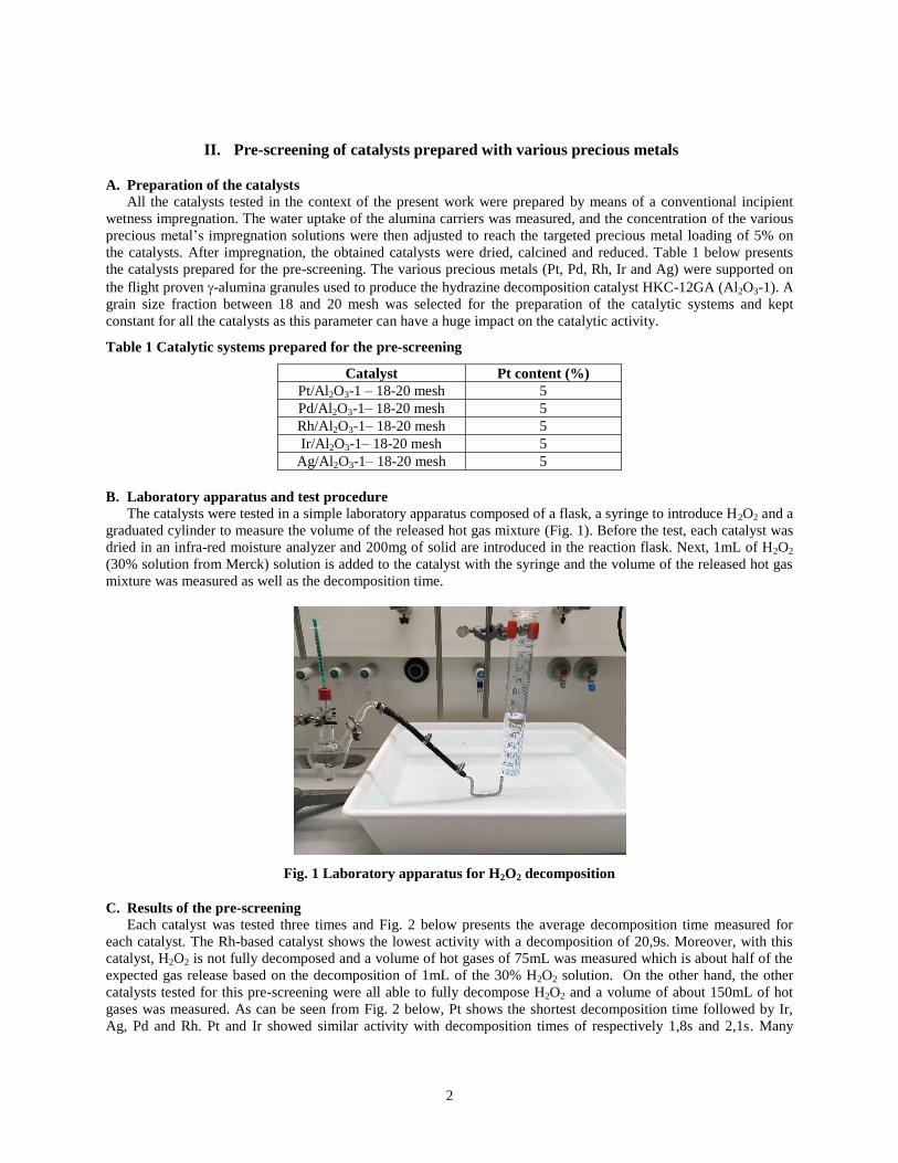
B. Laboratory apparatus and test procedure
The catalysts were tested in a simple laboratory apparatus composed of a flask, a syringe to introduce H2O2 and a
graduated cylinder to measure the volume of the released hot gas mixture (Fig. 1). Before the test, each catalyst was
dried in an infra-red moisture analyzer and 200mg of solid are introduced in the reaction flask. Next, 1mL of H2O2
(30% solution from Merck) solution is added to the catalyst with the syringe and the volume of the released hot gas
mixture was measured as well as the decomposition time.
Fig. 1 Laboratory apparatus for H2O2 decomposition
C. Results of the pre-screening
Each catalyst was tested three times and Fig. 2 below presents the average decomposition time measured for
each catalyst. The Rh-based catalyst shows the lowest activity with a decomposition of 20,9s. Moreover, with this
catalyst, H2O2 is not fully decomposed and a volume of hot gases of 75mL was measured which is about half of the
expected gas release based on the decomposition of 1mL of the 30% H2O2 solution. On the other hand, the other
catalysts tested for this pre-screening were all able to fully decompose H2O2 and a volume of about 150mL of hot
gases was measured. As can be seen from Fig. 2 below, Pt shows the shortest decomposition time followed by Ir,
Ag, Pd and Rh. Pt and Ir showed similar activity with decomposition times of respectively 1,8s and 2,1s. Many

3
different precursors of Pt are available by Heraeus which might have an big impact on the catalytic activity and Pt
was therefore selected for the fine screening presented below.
Fig. 2 Decomposition times measured during the pre-screening
III. Fine screening of Pt catalysts
A. Preparation of the catalysts and testing
The aim of this fine screening was to investigate the influence of some preparation parameters on the catalytic
activity of the Pt/Al2O3 system. Three different Pt precursors (A, B and C) were used to prepare the catalysts and
two different carriers were also studied, namely the -alumina granules used to produce the hydrazine decomposition
catalyst HKC-12GA (Al2O3-1) and an alternative -alumina granules (Al2O3-2). The choice of -alumina is critical
for this kind of catalytic bed as it was already shown in the past that -alumina supported catalyst tend to crack when
brought in contact with highly concentrated H2O2 solutions [11-12]. The size of the granules was again the fraction
between 18 mesh and 20 mesh. The catalytic systems tested during this fine screening are listed in Table 2 below.
These catalysts were prepared using the same incipient wetness impregnation method as the one used for the pre-
screening and the Pt loading was again kept constant and equal to 5%. The first tests for the fine screening were
performed with the 30% H2O2 solution, but with this concentration no difference could be observed between all the
very active Pt systems and the concentration had to be decreased down to 10% to better investigate the impact of the
studied parameters on the catalytic activity.
Table 2 Catalytic systems prepared for the fine screening
Catalyst Pt content (%)
Pt (A)/ Al2O3-1– 18-20 mesh 5
Pt (B)/ Al2O3-1– 18-20 mesh 5
Pt (C)/ Al2O3-1– 18-20 mesh 5
Pt (C)/ Al2O3-2– 18-20 mesh 5
B. Characterization of the catalysts
Characterization of the catalysts consisted of determination of the precious metal surface by CO-adsorption,
determination of the pore volume by Hg-porosimetry, scanning electron microscopy coupled with energy dispersive
X-ray spectroscopy (SEM-EDX) and transmission electron microscopy (TEM).
The precious metal surface area tests were performed in a TPDRO 1100 device from the Thermo Finnigan
Company. Before testing, the catalysts are reduced for 2h in a reductive gas mixture (95% Ar, 5% H2).
The Hg-porosimetry analysis were conducted using two devices namely a Pacal P140 and a Pascal P440 from
the company Thermo Fischer Scientific. Before testing, the samples are degassed at 150°C for 12h.
The SEM-EDX analyses were performed using the Scanning Electron Microscope Jeol JSM-IT100 equipped
with integrated energy dispersive X-ray analysis system, using a 20 keVelectron beam. The depth penetration for 20
keV incident electrons is about 1 μm; therefore, SEM-EDX provides quantitative analysis of elemental composition
of the specimen surface with a sampling depth of 1 μm. The methodology of investigation used is the following: one
layer of pellets for each catalyst sample were embedded in resin, cross-sectioned in half and polished. In the SEM a
BSE-picture (backscattered electrons) in minimum magnification was used to pick some characteristic/
representative pellets.
1,8
8,2
20,9
2,1
5,4
0 5 10 15 20 25
Pt/Al2O3-1
Pd/Al2O3-1
Rh/Al2O3-1
Ir/Al2O3-1
Ag/Al2O3-1
Decomposition time [s]

4
TEM investigations were conducted using a FEI Talos 20-200 transmission microscope at 200 kV. The
measurements were performed in TEM mode and in STEM using Bright Field (BF) imaging and HAADF detector.
Energy-dispersive x-ray spectroscopy was used to detect differences in local chemical composition.
C. Results of the fine screening and discussion
The decomposition times for the four catalysts are presented in Fig. 3 below. As expected, the decomposition
times measured with the diluted H2O2 solution are much longer and allowed us a better discrimination of the
catalytic systems. We observed full decomposition of the hydrogen peroxide and a volume of hot gases of 50mL
was measured, which corresponds to the volume expected for the decomposition of 1mL of a 10% H2O2 solution.
Fig. 3 Decomposition times measured during the fine screening
Among the three Pt precursors used for the preparation of the catalysts tested during this fine screening, Pt salt A
shows the lowest activity with a decomposition time of 51s. This is about two times, respectively three times longer
than the decomposition times observed for the catalyst prepared with precursor B and C. The SEM images of these
three catalysts are presented in Fig. 4 below. As can be seen from these images, precursors A tends to travel much
deeper in the alumina pores compared to precursors B and C and the alumina granules prepared with this salt are
almost homogeneously impregnated. On the other side, in the catalysts prepared with precursors B and C, Pt tends to
stay at the surface of the alumina granules and these catalysts present an egg-shell profile with much higher local
concentrations of Pt at the surface of the granules. This higher concentration of Pt at the surface of the granules
explains the higher activity for the decomposition of H2O2, which does not have to enter deeply the pores of the
catalyst to react on the active sites.
Fig. 4 SEM images of a) Pt (A)/ Al2O3-1, b) Pt (B)/ Al2O3-1, c) Pt (C)/ Al2O3-1
As can be seen from image b) and c), the egg-shell profile for the catalyst prepared with precursor B is sharper than
the one observed for catalyst prepared with precursor C and a rough estimation of the shell thickness showed that the
shell observed for precursor B is about two time thinner than for precursor C (respectively 50m and 100m).
Nevertheless, catalyst prepared with precursor C shows the highest activity with a decomposition time about two
times shorter than catalyst prepared with precursor B. The TEM images as well as the crystallite size distribution for
the catalysts prepared with precursors B and C are presented in Fig. 5 and Fig. 6 below.
As can be seen in the TEM images, the Pt nanoparticles obtained with precursor C are much smaller than the ones
observed for the catalyst prepared with precursor B. This observation is confirmed by the crystallite size distribution
presented in Fig. 6. For the catalyst Pt (B)/ Al2O3-1, a very broad distribution is obtained and most of the particles
51
32
16
7
0 20 40 60
Pt (A)/Al2O3-1
Pt (B)/Al2O3-1
Pt (C)/Al2O3-1
Pt (C)/Al2O3-2
Decomposition time [s]
a) b) c)

5
have a diameter comprised between 10 nm and 30 nm. On the other hand, a very narrow distribution is observed for
catalyst Pt (C)/ Al2O3-1 and most of the nanoparticles of Pt have a diameter comprised between 1 nm and 4 nm.
Fig. 5 TEM images of Pt (B)/ Al2O3-1 (left) and Pt (C)/ Al2O3-1 (right)
Fig. 6 Crystallite size distribution for catalysts Pt (B)/ Al2O3-1 (left) and Pt (C)/ Al2O3-1 (right)
This much smaller particle size, i.e. much better dispersion of the Pt observed with precursor C explains the higher
catalytic activity observed for this catalyst compared to the catalyst impregnated with precursor B. This better
dispersion was also confirmed by the metallic surface areas determined with the CO adsorption measurements
presented in Table 3 below. The catalyst prepared with Pt salt C shows a metallic surface area about five time bigger
than the one measured for precursor B.
Table 3 Metallic surface area measured for Pt (B)/ Al2O3-1 and Pt (C)/ Al2O3-1
Catalyst Metallic surface area (m2/g)
Pt (B)/ Al2O3-1– 18-20 mesh 2,1
Pt (C)/ Al2O3-1– 18-20 mesh 11,0
The Pt precursor C shows the highest activity among the three precursors tested during the fine screening. This
precursor was therefore selected to prepare one additional catalyst supported on an alternative -alumina, namely
Al2O3-2. This additional catalyst shows improved catalytic activity compared to the one prepared on the
conventional alumina, with a decomposition time about two time shorter. The various characterizations performed
on this additional catalyst are presented in Fig. 7 below. The results obtained for the catalyst supported on the
alternative alumina are very similar to the one observed for the material impregnated on the standard alumina Al2O3-
1. The SEM image presented in Fig. 7 below shows a relatively sharp egg-shell profile with a shell-thickness of
about 130 m. The TEM investigations also shows very similar results as the ones observed for the standard
0
20
40
60
80
100
120
0,0 0,5 1,0 1,5 2,0 2,5 3,0 3,5 4,0 4,5 5,0 5,5 6,0 6,5 7,0 7,5 8,0
freq
uen
cy
cristallite size [nm]
0
5
10
15
20
25
30
5 7 9 11 13 15 17 19 21 23 25 27 29 31 33 35 37 39
freq
uen
cy
cristallite size [nm]

6
alumina. Some very small Pt nanoparticle can be observed on the TEM image below and the crystallite size
distribution shows a very narrow distribution with most of the particles having a size comprised between 1 nm and 3
nm. These nanoparticles are slightly smaller than the one observed for the catalyst prepared on the conventional
alumina, which might partially explain why this catalyst shows a better catalytic activity during the H2O2
decomposition test performed in the laboratory apparatus.
Fig. 7 SEM (left), TEM (middle) images and crystallite size distribution (left) for the catalyst Pt (C)/ Al2O3-2
An additional explanation for this improved activity can be the differences observed in the pore volume and the pore
diameter distribution presented in Table 4 and Fig. 8 below. The catalyst supported on the alternative alumina
Al2O3-2 shows a total pore volume about two times bigger than the conventional alumina granules. Moreover, the
pores size distribution presented in Fig. 8 below shows that the highest contribution to the total pore volume comes
from the pores with a diameter between 3 nm and 5 nm for Al2O3-1, whereas the highest contribution to the total
pore volume for Al2O3-2 comes from the pores having a diameter comprised between 5 nm and 10 nm. These
differences in the micropores distribution might explain the better activity observed for the catalyst supported on the
alternative alumina and further investigations are needed to better understand the influence of this parameter on the
catalytic activity.
Table 4 Pore volume and average pore diameter for catalyst Pt (C)/ Al2O3-1 and Pt (C)/ Al2O3-2
Catalyst Pore volume (cm3/g) Average pore diameter (nm)
Pt (C)/ Al2O3-1– 18-20 mesh 0,16 10,03
Pt (C)/ Al2O3-2– 18-20 mesh 0,30 13,57
0
20
40
60
80
100
120
140
160
180
0,0 0,5 1,0 1,5 2,0 2,5 3,0 3,5 4,0
freq
uen
cy
cristallite size [nm]

7
Fig. 8 Pore size distribution for catalysts Pt (C)/ Al2O3-1 (left) and Pt (C)/ Al2O3-2 (right)
IV. Monopropellant test campaign
A. Catalysts selected for the campaign
Four catalysts (A, B, C and D) were prepared for the test campaign performed by ONERA in their
monopropellant test facility. The catalysts listed in Table 5 were prepared with the Pt-precursor C, which showed the
most promising results during the laboratory screening. Catalyst A, B and C were prepared with three different
granules sizes of the Al2O3-1 alumina. Catalyst D was prepared with the alternative -alumina Al2O3-2 described
before and with the same granules size as the one used to produce catalyst A. The Pt content was again kept constant
and equal to 5%.
Table 5 Catalysts for the monopropellant test campaign
Catalyst Pt content (%)
A - Pt (C)/ Al2O3-1 – 10-14 mesh 5
B - Pt (C)/ Al2O3-1 – 18-20 mesh 5
C - Pt (C)/ Al2O3-1 – 20-25 mesh 5
D - Pt (C)/ Al2O3-2 – 10-14 mesh 5
B. Description of the monopropellant test facility
The monopropellant test facility consists basically of the three following main components: the inlet manifold
connected to the hydrogen peroxide feed line, an injector plate and the decomposition chamber containing the
catalyst particles (Fig. 9). The injector plate was especially designed to spread the liquid hydrogen peroxide all over
the cross section of the decomposition chamber. This chamber consists of an Inconel cylinder closed at both ends by
refractory steel meshes to maintain the catalyst particles inside the decomposition chamber.
Fig. 9 Monopropellant test facility
This chamber is connected to a measurement module measuring the decomposition temperature at the outlet of the
catalytic bed thanks to three thermocouples and the decomposition chamber pressure. The instrumentation of this
facility also includes a Coriolis oxidizer mass flow measurement and temperature and pressure measurements of the
liquid oxidizer upstream the manifold.
C. Test results
For this test campaign, each test was performed during 10 s and the oxidizer mass flow rate was kept constant
and equal to 90 g/s. Indeed, it was important to keep this parameter constant to get a direct comparison between the
four different catalysts since the transient phase duration depends on the oxidizer mass flow rate. A lower oxidizer
mass flow rate leads to a higher transient phase duration and vice-versa.

8
Thanks to a constant tank pressure during the monopropellant test, the oxidizer mass flow rate is stable during the
second part of the test due to steady temperature at the outside of the decomposition chamber (Fig. 10). During the
first part of this test (up to 5 s), the decomposition temperature increases continuously which leads to a slight
decrease of the oxidizer mass flow rate. Before going up to about 910 K, the decomposition temperature shows a
short plateau at temperature of about 360 K which corresponds to the water decomposition temperature.
Fig. 10 Results of a test performed with the catalyst sample A
Figure 11 below presents the decomposition temperature in the chamber, which was normalized according to Eq.1.
𝑇𝑛𝑜𝑟𝑚 =𝑇𝑑𝑒𝑐−𝑇𝑖𝑛𝑗
𝑇𝑎𝑑−𝑇𝑖𝑛𝑗 (1)
With Tnorm the normalized temperature, Tdec the measured decomposition temperature, Tinj the injection temperature
of the liquid oxidizer and Tad the adiabatic decomposition temperature, which was obtained thanks to a
thermochemical equilibrium code. This equation was used to overcome the variations in the injection temperature as
well as the variation observed in the hydrogen peroxide concentration from test to test.
Before comparing the activity of the catalysts, each sample was submitted to four consecutives monopropellant tests
to insure a good reproducibility of the results. The temperature evolution for the four tests performed on catalyst C
are presented in Fig. 11 below. As can be seen from this figure, the temperature evolution for the last three
monopropellant tests match well and an efficiency of 97.4% was reached based on the normalized temperature.
Fig. 11 Decomposition temperature evolution of catalyst sample C for the four tests
Finally, the normalized temperatures for the four catalyst samples are presented and compared in Fig. 12 below.
First, the comparison between catalyst A, B and C shows that the smallest the particle size, the shorter the transient
time and the higher the efficiency based on the normalized temperature. On the other hand, catalyst D, which was
prepared with the same particle size as catalyst A but with the alternative alumina Al2O3-2, shows improved
efficiency as well as a shorter transient phase duration. These results confirm the better catalytic activity of the
catalyst supported on Al2O3-2, which was already observed during the laboratory screening.

9
Fig. 12 Comparison between the decomposition temperatures of the four catalyst samples
The final choice for the best catalytic system was finally made between catalyst C and D. On the one hand shows
catalyst C a shorter transient time (2.5 s against 3.2 s). On the other hand, catalyst D supported on the alternative
alumina granules shows improved efficiency compared to catalyst C (respectively 98.5% and 97.4%). Moreover, the
post-test analysis of the catalytic bed prepared with sample C showed the tendency of these very fine particles to
aggregation and some bigger particles were observed. This aggregation could have a negative impact on the
performances of the catalyst bed during longer cumulative test durations and consequently catalyst sample D was
selected for the hybrid firing test campaigns reported in Ref. 13 and Ref. 14.
V. Conclusion
A reliable and effective catalytic bed is one of the key elements for the development of a highly concentrated
hydrogen peroxide thruster. A pre-screening performed at Heraeus in a very simple laboratory apparatus on various
precious metals supported on the flight proven -alumina granules used to produce the hydrazine decomposition
catalyst HKC-12GA (Al2O3-1) showed that Pt is the most active precious metal for the catalytic decomposition of
H2O2. A more detailled screening was then performed on several Pt catalysts prepared with three different Pt
precursors as well as two different aluminas. These catalysts were fully characterized using various techniques like
SEM-EDX, TEM and Hg-porosimetry. The most effective combination was found to be Pt (C)/Al2O3-2. This
catalyst shows the highest Pt dispersion, with nanoparticles of about 2 nm as well as a good egg-shell profile. The
monopropellant test campaign performed by ONERA on four Pt catalysts confirmed the better activity of this
catalytic system under real conditions (87,5% H2O2). Surprisingly, the several hot-firing tests performed on this
catalytic system did not show a noticeable ageing of the catalyst and the decomposition activity of the catalyst
remained almost unchanged after the exposition to several kilograms of highly concentrated hydrogen peroxide. A
post-test characterization of the catalyst would be necessary to further understand the ageing behavior of this
catalytic system during the hot-firing tests.
References
[1] Gohardani, A. S., Stanojev, J., Demairé, A., Anflo, K., Persson, M., Wingborg, N., and Nilsson, C., “Green Space Propulsion:
Opportunities and Prospects,” Progress in Aerospace Sciences, Vol. 71, Nov. 2014, pp. 128–149.
doi: 10.1016/j.paerosci.2014.08.001
[2] Masse, M., Allen, M., Spores, R., and Driscoll, A. A., “AF-M315E Propulsion System Advances and Improvements,” 52nd
AIAA/SAE/ ASEE Joint Propulsion Conference, AIAA Propulsion and Energy Forum, AIAA Paper 2016-4577, 2016.
doi:10.2514/6.2016-4577
[3] Dolci, S., Belli Dell’Amico, D., Pasini, A., Torre, L., Pace, G., and Valentini, D., “Platinum Catalysts Development for 98%
Hydrogen Peroxide Decomposition in Pulsed Monopropellant Thrusters,” Journal of Propulsion and Power, Vol. 31, No. 4,
2015, pp. 1204–1216.
doi:10.2514/1.B35590
[4] Torre, L., Pasini, A., Romeo, L., Cervone, A., and d’Agostino, L., “Performance of a Monopropellant Thruster Prototype
Using Advanced Hydrogen Peroxide Catalytic Beds,” Journal of Propulsion and Power, Vol. 25, No. 6, 2009, pp. 1291–1299.
doi:10.2514/1.44354

10
[5] Koopmans, R. J., Shrimpton, J. S., Roberts, G. T., and Musker, A. J., “A One-Dimensional Multicomponent Two-Fluid
Model of a Reacting Packed Bed Including Mass, Momentum and Energy Interphase Transfer,” International Journal of
Multiphase Flow,Vol. 57, Dec. 2013, pp. 10–28.
doi:10.1016/j.ijmultiphaseflow.2013.06.005
[6] Maia, F. F., Gouvea, L. H., Pereira, L. G. F., Vieira, R., and De Souza Costa, F., “Development and Optimization of a
Catalytic Thruster for Hydrogen Peroxide Decomposition,” Journal of Aerospace Technology and Management, Vol. 6, No. 1,
2014, pp. 61–67. doi:10.5028/jatm.v6i1.286
[7] Bonifacio, S., Russo Sorge, A., Krejci, D., Woschnak, A., and Scharlemann, C., “Novel Manufacturing Method for Hydrogen
Peroxide Catalysts:APerformanceVerification,” Journal of Propulsion and Power, Vol. 30, No. 2, 2014, pp. 299–308.
doi:10.2514/1.B34959
[8] Pirault-Roy, L., Kappenstein, C., Guerin, M., Eloirdi, R., and Pillet, N., “Hydrogen Peroxide Decomposition on Various
Supported Catalysts Effect of Stabilizers,” Journal of Propulsion and Power, Vol. 18, No. 6, 2002, pp. 1235–1241.
doi:10.2514/2.6058
[9] Rusek, J. J., “New Decomposition Catalysts and Characterization Techniques for Rocket-Grade Hydrogen Peroxide,” Journal
of Propulsion and Power, Vol. 12, No. 3, 1996, pp. 574–579.
doi:10.2514/3.24071
[10] Romeo, L., Torre, L., Pasini, A., Cervone, A., and d’Agostino, L., “Performance of Different Catalysts Supported on
Alumina Spheres for Hydrogen Peroxide Decomposition,” 43rd AIAA/ASME/SAE/ ASEE Joint Propulsion Conference & Exhibit,
AIAA Paper 2007- 5466, 2007.
doi:10.2514/6.2007-5466
[11] Surmacz, P., “Influence of Various Types of Al2O3∕MnxOy Catalysts on Performance of a 100 MM Chamber for
Decomposition of 98%+ Hydrogen Peroxide,” Transaction of the Institute of Aviation, Vol. 240, No. 3, 2015, pp. 58–68.
doi:10.5604/05096669.1194986
[12] Pasini, A., Torre, L., Romeo, L., Cervone, A., and d’Agostino, L., “Testing and Characterization of a Hydrogen Peroxide
Monopropellant Thruster,” Journal of Propulsion and Power, Vol. 24, No. 3, 2008, pp. 507–515.
doi:10.2514/1.33121
[13] Lestrade, J.Y., Prévot, P., Messineo, J., Anthoine, J., Casu, S. and Geiger, B., “Development of a Catalyst for High
Concentrated Hydrogen peroxide,” 6th International Symposium on Propulsion for Space Transportation (Space Propulsion),
Roma, Italy, May 2016.
[14] Anthoine, J., Lestrade, J.Y., Messineo, J. and Casu, S., “Performances of a Multi-Pulsed Hybrid Rocket Engine Operating
with Highly Concentrated Hydrogen Peroxide”, 53rd AIAA/SAE/ASEE Joint Propulsion Conference, Atlanta, USA, July 2017
Recommended