Determination of the coefficient of expansion of a carbon tube and its assembly for thermal compensation of metrological structures
Salma EL ASMAI1 *, François HENNEBELLE1, Thierry COOREVITS2, Jean-François
FONTAINE1
1UBFC, Avenue des plaines de l’Yonne, 89000 Auxerre, France
2Ecole nationale supérieure des Arts et Métiers – Laboratoire MSMP, Lille, France
Abstract. Composite materials are increasingly used in 3D metrology devices. Their use is justified by their interesting mechanical properties including their low density and good rigidity but especially their low coefficient of thermal expansion. In fact, in order to improve production
efficiency, companies nowadays integrate more and more control equipment directly in situ. These are then subject to thermal variations. The use of composite materials is an interesting approach. However, in some cases, the lack of knowledge of their coefficient of thermal expansion and their behavior might increase measurement uncertainties. The objective is to study the thermal behavior of a carbon tube alone and the same tube with aluminium fixing elements at its extremities, in order to determine the coefficients of expansion of the carbon alone and to quantify the influence
of the fixation with aluminium elements. This experiment makes it possible to directly compensate the dimensional variations of the metrological structure depending on the temperature variations and thus to limit measurement uncertainties. The thermal expansion coefficients of the carbon tube and its assembly are determined by measuring relative variations in height with a ZERODUR® reference bar. The whole is positioned in a climatic chamber. *
1 Introduction
Tubes made of braided carbon fiber are increasingly used in metrological structures. Indeed,
in addition to their lightweight, their coefficient of thermal expansion (CTE) is almost zero.
In the context of the factory of the future 4.0 and the installation of metrology equipment
closer to production, these products are very interesting and even unavoidable. As a result,
segmented Ball Bars or Articulated Arm Coordinate Measuring Machines (AACMM) for
example use this type of components in their structure in order to guarantee the dimensional
stability of the equipment and thus the traceability of the measurements during thermal
variations.
* Corresponding author: [email protected]
© The Authors, published by EDP Sciences. This is an open access article distributed under the terms of the Creative Commons Attribution License 4.0 (http://creativecommons.org/licenses/by/4.0/).
19th International Congress of Metrology, 26003 (2019) https://doi.org/10.1051/metrology/201926003

Carbon tube manufacturers traditionally indicate on their product records a coefficient of
thermal expansion equal to zero for these carbon fiber bars with an associated uncertainty of
2.10-6 K-1 or they provide only the coefficient of the fiber regardless of the matrix and fiber
orientation. Thus, the experiments carried out to determine the CTE of carbon fiber tubes
mainly address the case where the tubes are subject to significant temperature variations
(from -60 °C to 180 °C). In these cases, systems with a “medium” measurement uncertainty
can be used, namely Linear Variable Differential Transformer (LVDT) sensors [1], optical
systems based on interferometry [2] and so on. Note that today, it is possible to design
composite materials based on carbon nanotubes with a coefficient of negative thermal
expansion [3].
The objective of the work is to estimate the real expansion coefficient of these tubes, in particular given that they are assembled on structures via two aluminium layers, one at each
end of the tube. To do this, we will determine two different expansion coefficients, namely
the CTE of the carbon fiber tube alone and the CTE of the assembly made of the carbon tube
and the aluminium alloy.
It will be demonstrated that the CTE of an assembled carbon tube is therefore not necessarily
negligible in terms of measurement uncertainties, when the measuring devices are used in
the shop of floor and industrial environments where the temperature is not regulated. This
problem is at the heart of the constraints of the factory of the future.
2 Justification of the testing method
To determine The CTE of a braided carbon tube (of annular section) with low uncertainty is not easy.
Therefore, it is impossible to perform measurements by extensometry to determine the
coefficient of expansion of this type of structure. In fact, since the CTE is small, if we
consider that the CTE of the carbon fiber in the composite matrix has is 10-6 K-1, then the
total elongation of a tube 500 mm long is 0.5 μmK-1. In order to carry out this experiment, it
is necessary to heat the tube. This is problematic because the order of magnitude of
measurement uncertainties of the gauges under the influence of temperature variations is the
same as the dimensional variation that can be observed.
It is not conceivable either to directly measure the variation of the tube length under the effect
of temperature variations thereof, even on a good three-dimensional measuring machine
(CMM). Indeed, the measurement uncertainties of the CMMs being a function of the measured length, the measurement uncertainty induced over a length of 500 mm will be close
to 1 µm, without considering the disturbances of the machine under the effect of the
temperature of the tube.
To achieve this type of measurement, one of the solutions is to measure by “length
comparison” by means of another reference tube whose characteristics are perfectly known.
The choice was to use a ZERODUR® bar with a very low CTE (10-8 K-1) [4] of the same
nominal length as the tube to be characterized, and to measure the relative length variation
between the ZERODUR ® and the tube at different temperatures. Knowing the temperature
and the variation of the relative length, it is easy to evaluate the CTE of the tube.
3 Set up of the experiment and the heating section
The objective is to create a temperature-controlled heating section that can be used to test
braided composite tubes. The upper face of the ZERODUR® and the upper plane of the tube
must be accessible to be measured with a touch probe by the CMM. The heating section must
2
19th International Congress of Metrology, 26003 (2019) https://doi.org/10.1051/metrology/201926003

be insulated to allow stabilization and regulation of the heating section but also to avoid
heating the machine locally, which would lead to measurement errors.
The CMM used is the machine ZEISS UPMC 8/12/6 Arts et Métiers ParisTech, center of
Lille, equipped with a measuring head VAST Gold type. The measurement uncertainty in the
measurement direction (Z axis) of the CMM is 0,5 µm+ 𝐿 [mm]
900 µm (k = 2).
The ZERODUR® bar was custom-made by SCHOTT [5], has a length of 510.035 mm and
a diameter of 30 mm. It is held on a specific support allowing it to be held unrestrained in a
vertical position (Fig. 1a). The heating system is provided by a heating tube made by the
composite team of Arts et Métiers ParisTech, Center of Lille. A heated wired network sewn
before polymerization on a composite web is arranged around a zinc tube. A specific box
makes it possible to regulate at a defined setpoint temperature. The temperature is measured
in two points of the carbon tube through two probes PT100 son 4 disposed on small copper
plates for physical filtering thermal inertia of the temperature measurement (Fig. 1b).
Fig. 1.a) ZERODUR® in its socket. – b) Heating tube and instrumented carbon tube.
Fig. 2 presents the schematic diagram of the assembly of the carbon tube and the
ZERODUR® in the heating chamber, allowing the characterization of changes in the length
of the carbon tube as a function of temperature. The glass wool insulation is held in place by
2 PVC pipe pipes of diameters 100 mm and 160 mm respectively. A shim made of thermally
insulating material was installed between the heating assembly and the CMM table to prevent
diffusion thermal leakage.
Fig. 3a shows the assembly before closing. The device is closed by a top plate to help hold the assembly in place, isolate the system from the outside and thus ensure quality
measurements on the CMM (Fig. 3b).
a b
3
19th International Congress of Metrology, 26003 (2019) https://doi.org/10.1051/metrology/201926003

Fig. 2. Diagram of the assembly set up for the thermal characterization of carbon tube.
Fig. 3. a) Device before closing. – b) Device installed on the CMM.
4 Experiments
4.1. Evaluation of the coefficient of thermal expansion of the carbon tube
The assembly is gradually heated up to 30 °C and the height variations between the upper
face of the ZERODUR® and the upper plane of the carbon tube are noted and saved.
The tests were carried out 3 times at 4 different temperatures (22 °C, 25 °C, 27 °C and 30
°C).
The CTE of the carbon tube is then estimated at 1.2 10-6 K-1 with an uncertainty of 0.2 10-6
K-1 (k = 2) essentially related to thermal leakage and temperature gradients. in the tube (about
1 °C thermal gradient between the top and bottom of the tube at 30 °C for example).
Measurements of height variation on CMM are repeatable to about 0.3 μm.
a b
4
19th International Congress of Metrology, 26003 (2019) https://doi.org/10.1051/metrology/201926003
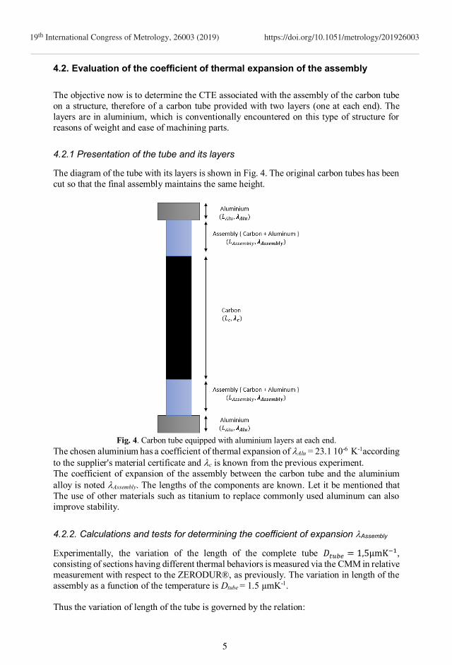
4.2. Evaluation of the coefficient of thermal expansion of the assembly
The objective now is to determine the CTE associated with the assembly of the carbon tube
on a structure, therefore of a carbon tube provided with two layers (one at each end). The
layers are in aluminium, which is conventionally encountered on this type of structure for
reasons of weight and ease of machining parts.
4.2.1 Presentation of the tube and its layers
The diagram of the tube with its layers is shown in Fig. 4. The original carbon tubes has been
cut so that the final assembly maintains the same height.
Fig. 4. Carbon tube equipped with aluminium layers at each end.
The chosen aluminium has a coefficient of thermal expansion of Alu = 23.1 10-6 K-1according
to the supplier's material certificate and c is known from the previous experiment.
The coefficient of expansion of the assembly between the carbon tube and the aluminium
alloy is noted Assembly. The lengths of the components are known. Let it be mentioned that
The use of other materials such as titanium to replace commonly used aluminum can also
improve stability.
4.2.2. Calculations and tests for determining the coefficient of expansion Assembly
Experimentally, the variation of the length of the complete tube 𝐷𝑡𝑢𝑏𝑒 = 1,5µmK−1,
consisting of sections having different thermal behaviors is measured via the CMM in relative
measurement with respect to the ZERODUR®, as previously. The variation in length of the
assembly as a function of the temperature is Dtube = 1.5 µmK-1.
Thus the variation of length of the tube is governed by the relation:
5
19th International Congress of Metrology, 26003 (2019) https://doi.org/10.1051/metrology/201926003

2 𝜆𝐴𝑙𝑢 . 𝐿𝐴𝑙𝑢 + 2 𝜆𝐴𝑠𝑠𝑒𝑚𝑏𝑙𝑦 . 𝐿𝐴𝑠𝑠𝑒𝑚𝑏𝑙𝑦 + 𝜆𝑐 . 𝐿𝑐 = 𝐷𝑡𝑢𝑏𝑒 = 1,5 µmK−1 (1)
Finally :
𝝀𝑨𝒔𝒔𝒆𝒎𝒃𝒍𝒚 =𝟏.𝟓−𝝀𝒄.𝑳𝒄−𝟐 𝝀𝑨𝒍𝒖.𝑳𝑨𝒍𝒖
2 𝐿𝐴𝑠𝑠𝑒𝑚𝑏𝑙𝑦= 𝟏. 𝟑 𝟏𝟎−𝟔 𝐊−𝟏 (2)
5. Conclusion and perspective The studies carried out make it possible to show that the failure to take into account the
coefficients of expansion of the assemblies can have heavy consequences on the variations
of length. If we consider a segmented Ball Bar that would be equipped with this type of
inserts, the error on the length caused by a 35 mm long insert integrated into a carbon tube
corresponds to an error of 0.2 µmK-1.
If we consider a Ball Bar consisting of 5 sections so 10 inserts, the error on the length is then
2 microns per degree. The error is therefore far from negligible for devices installed in
uncontrolled environments. Unfortunately, since calibrations are done in an air-conditioned
laboratory, this type of problem is never observed and can cause large errors in applications
in an uncontrolled environment.
The good knowledge of the materials used and the consequence of their assembly is an important work that must be carried out in order to improve the corrections of metrology
devices for the needs of the factory of the future.
References
1. R. Shubham, D. Rahul, J. Shivang and G.D. Acharya, “Experimental evaluation of Coefficient of Thermal Expansion of Carbon Fiber Reinforced Polymer tube,” IJARED
4, (2017).
2. D. Chengzhi, L. Kai, J. Yuxi, A. Dwayne, and Z. Dongsheng, “Evaluation of thermal
expansion coefficient of carbon fiber reinforced composites using electronic speckle
interferometry,” Opt Express 26, pp. 531-543, (2018).
3. K. Shirasu, G. Yamamoto, I. Tamaki, T. Ogasawara, Y. Shimamura, Y. Inoue and T.
Hashida, “Negative axial thermal expansion coefficient of carbon nanotubes:,” Carbon,
95, (2015).
4. R. Jedamzik, T. Johansson and T. Westerhoff, “Modeling of the thermal expansion
behavior of ZERODUR (R) at arbitrary temperature profiles,” in Proceedings of SPIE,
(2010). 5. 5. [Online]. Available: https://www.schott.com/english/index.html.
6
19th International Congress of Metrology, 26003 (2019) https://doi.org/10.1051/metrology/201926003
Recommended
![MicroPositioning, NanoPositioning, NanoAutomation Tutorial ... · Coefficient of Thermal Expansion (CTE) [K-1] (1/ kelvin) C Capacitance (F) [A s / V] d ij Piezo modulus (tensor components)](https://img.dokumen.tips/doc/110x75/5f19de03fb715315cf219673/micropositioning-nanopositioning-nanoautomation-tutorial-coefficient-of-thermal.jpg)