Designing of Energy Efficient Rotary Steam Coil
Air Pre-Heater (SCAPH) for Fossil Fueled
Thermal Power Plant
Sunil Kumar Gupta
Head, Operation and Efficiency Department
Sasan Power Limited, Reliance Power
Singrauli, India
Arijit Debroy Senior Manager, Efficiency Department
Sasan Power Limited, Reliance Power
Singrauli, India
Abstract: Steam coil air preheaters (SCAPH) are found in
most fossil-fueled utility and large industrial power plants.
Their primary function is to pre-heat combustion air
before it enters rotary regenerative air preheater or
recuperative type air preheater. SCAPH provides
corrosion protection for the air pre heater and maintains
its cold end average temperature above acid dew point
temperature during cold stringent weather condition. Most
units use vertical, fixed finned tube coils embedded in the
ductwork connection of the discharge side of combustion
air source, Forced Draft fans, and the cold end inlet of Air
Pre-Heater. This equipment can also have an additional
purpose of preheating the combustion air during unit start-
up by increasing the ambient air temperature up to a
desirable temperature to reduce fuel oil consumption, thus
aiding operators to take pulverizer into service early. Along
with the advantages of this static bulky heat exchanger
there lays a hidden disadvantage which impacts the
auxiliary power consumption during normal unit operation
at normal ambient conditions. As it is present in the
discharge of forced draft fan a considerable amount of
pressure drop occurs across the coils which leads to an
increase of forced draft fan loading thus leading to an
increase in auxiliary power consumption even in normal
weather conditions. Without hampering the normal
functionality of the SCAPH system an innovative approach
has been taken and described in this paper through
redesigning of a Static SCAPH system into a Rotary
SCAPH system.
Keywords: Steam coil air preheater, air preheater, rotary
equipment, auxiliary power, retrofit, innovation,
modification, energy efficiency, SCAPH
I. INTRODUCTION
Heating and cooling systems technology is one of the
most important areas of mechanical engineering.
Wherever heating and cooling of fluids is incorporated in
a system we will find a heat exchanger. Heat exchangers
have wide industrial applications and it is practically
inexhaustible. In our basic study of heat transfer
equipment in modern power stations, we often come
across the term Steam coil air pre-heater (SCAPH) which
is a heat exchanger used to heat atmospheric air to the
required process temperature by means of superheated
steam in thermal power industry. Steam flow inside the
tube while air passes over the finned tubes. It is generally
used for heating process air or combustion air. SCAPH
has extensive uses in all High Capacity Boilers and
Recovery Boilers. Steam coil preheater is used to heat
inlet air to air preheater type (APH) in order to raise the
cold end temperature thus preventing acid dew point
corrosion. This type of equipment is normally
incorporated into design of a boiler unit for low load
operation and it can be used during unit start-up operation
also. It has finned tubes which increases heat exchange
surface area. It is generally located in the duct between
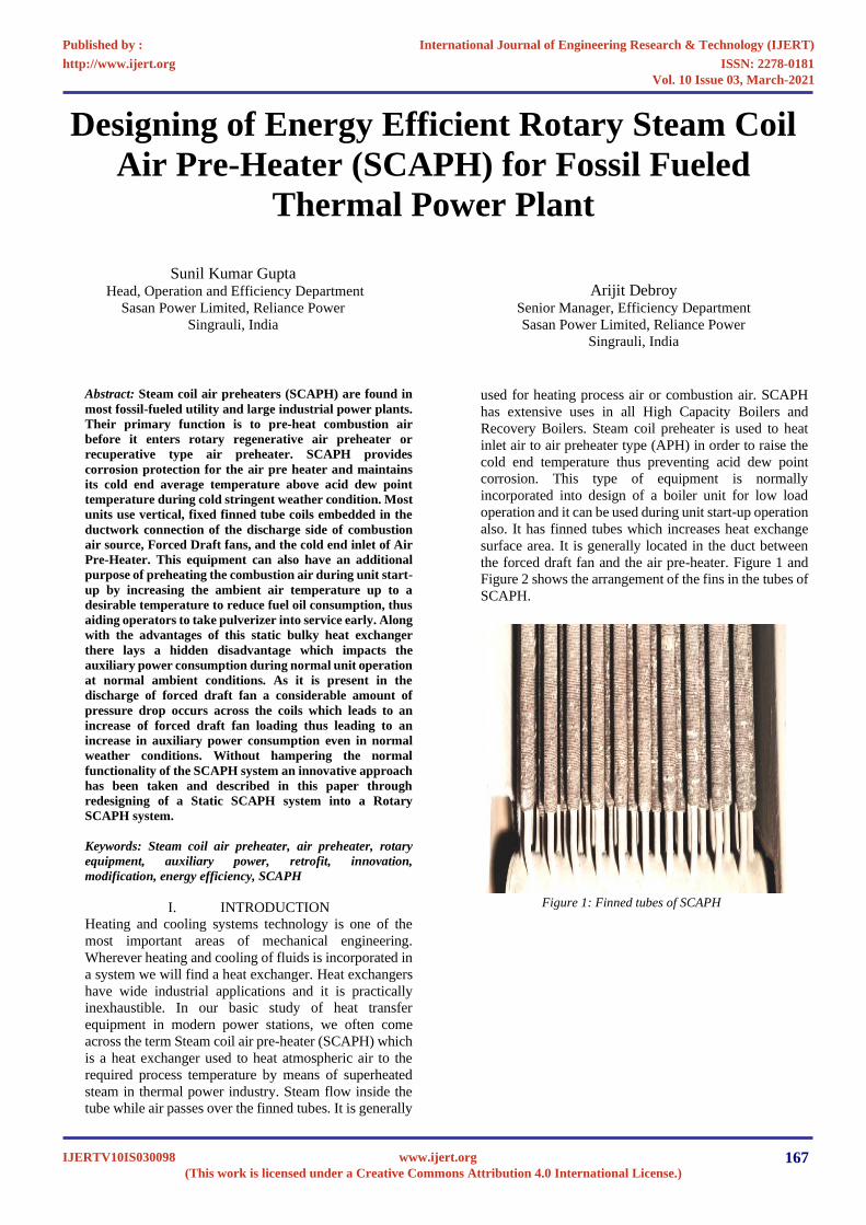
the forced draft fan and the air pre-heater. Figure 1 and
Figure 2 shows the arrangement of the fins in the tubes of
SCAPH.
Figure 1: Finned tubes of SCAPH
International Journal of Engineering Research & Technology (IJERT)
ISSN: 2278-0181http://www.ijert.org
IJERTV10IS030098(This work is licensed under a Creative Commons Attribution 4.0 International License.)
Published by :
www.ijert.org
Vol. 10 Issue 03, March-2021
167

Figure 2: Close view of the fins
II. INTRODUCTION TO AIR PRE-HEATER (APH)
AND DISCUSSION ON COLD-END CORROSION
Air pre-heater is a heat recovery equipment, which
improves the efficiency of boiler and also reduces the fuel
consumption to extent of nearly 5 percent depending on
duty. Figure 3 shows the rotary regenerative air pre heater
and its major components and flow path of air and flue gas
through it. In Air pre-heater the combustion air is preheated
before admitting the air to combustion zone or furnace. The
air preheating can be heated up to 300°C depending on type
of combustion equipment. Since the heat is extracted from
flue gas, the temperature of the flue gas can fall below the
acid dew point temperature which generally ranges
between 90°C to 110°C for Indian coals. As the ambient
temperature falls down there is possibility that overall bulk
mean temperature of the gas may fall below 110°C. SO3
and H2O present in the flue gas start to reacts with each
other at such a lower temperature. Figure 4 shows the
values of sulphuric acid dew points as a function of
sulphite content in the flue gas and moisture. To increase
the efficiency of the boiler SCAPH is introduced before air
pre-heater. In SCAPH the low temperature ambient air is
heated by low pressure steam to avoid cold-end corrosion.
Apart from that pre heating combustion air by usage of
SCAPH during unit light up aids in reduction of fuel oil
consumption by enabling operators to take pulverisers
early.
But during normal ambient temperature conditions and full
load operation of thermal units SCAPH loses its usefulness
and becomes a bulky burden as an auxiliary. This system
imposes a resistance on the forced draft fans by the
constant pressure drop across it. In this technical paper we
will discuss the methodology of converting the static
auxiliary into a dynamic rotary equipment through which
we can reduce the resistance in the flow path of combustion
air thus extracting benefit from the SCAPH system even
during normal ambient conditions and full load unit
operation.
Figure 3: Regenerative Rotary Air Pre-heater [1]
Figure 4: Calculated sulfuric acid dew points of typical combustion
flue gases, as a function of SO3 content, and water vapor content [2]
III. INTRODUCTION TO THE IMPLEMENTATION
SITE
The retrofitting of the SCAPH system and implementation
has been carried out in Sasan Ultra Mega Power Plant
(SUMPP) which is a subsidiary of Reliance Anil
Dhirubhai Ambani group located in Singrauli district of
Madhya Pradesh. The plant capacity is 3960 MW (6 X 660
MW) based on Super Critical Technology having the best
in class efficiency. It provides power at most competitive
tariff in the country to 14 DISCOMs in 7 states. Sasan
Power Limited (SPL) also has a mining production
capacity of nearly 20 million metric ton per annum
(MTPA) which is made possible by the “State of Art”
mining equipment and Largest Size of Heavy Earth
Moving Machinery (HEMM).
SPL is one of the largest integrated thermal power plant
with captive coal mines at single location. SPL is operating
at full capacity on continuous basis since commissioning,
setting & raising
benchmarks for the power industry every day. The plant
has achieved numerous awards & accolades in all areas of
operations and efficiency. On the path of inclusive growth,
it is making a positive impact on the life of surrounding
community by way of education, healthcare, and training
for skill development.
International Journal of Engineering Research & Technology (IJERT)
ISSN: 2278-0181http://www.ijert.org
IJERTV10IS030098(This work is licensed under a Creative Commons Attribution 4.0 International License.)
Published by :
www.ijert.org
Vol. 10 Issue 03, March-2021
168

• Design Meteorological Details: The elevation of
power plant is 275 to 320 meter above sea level with
design ambient temperature (dry-bulb temperature) of
32 °C and the extreme atmospheric temperature
ranges between maximum of 42°C, minimum 8.1 °C.
• Boiler: The Boiler at SPL is a supercritical, variable-
pressure operation, spiral tube once-through, single
furnace, single reheat, tangential firing, balanced
draft, semi outdoor arrangement, two-pass type
manufactured by Shanghai Boiler Works Co. Ltd.
Table 1: Boiler, Turbine and Forced Draft Fan Performance Data at Design Coal BOILER DESIGN PARAMETERS
PARTICULARS UOM TMCR CONDITIONS
Calculated thermal efficiency of Boiler % 87.34
Coal consumption TPH 344.3
Excess Air at Furnace outlet 1.2
Gas Temperature Inlet of APH °C 352
Primary Air Temperature leaving Primary Air Fan °C 42
Secondary Temperature leaving Forced Draft Fan °C 36
Primary Air Temperature at outlet of APH °C 321
Secondary Air Temperature at outlet of APH °C 327
Boiler Exhaust Gas temperature °C 141
TURBINE DESIGN PARAMETERS
Load MW 660
Main Steam Pressure MPa 24.2
Main Steam Temperature °C 566
Main Steam/ Reheat Steam Flow TPH 1975.8 / 1658
Reheat Steam Inlet and Outlet Pressure MPa 4.65 / 4.21
Reheat Steam Inlet and Outlet Temperature °C 321.9 / 566
Running Speed RPM 3000
Cooling Water Inlet and Outlet Temperature °C 32 / 42
Feed Water Inlet Temperature °C 280.9
FD FAN DETAILED PARAMETERS
Capacity of FD Fan at Design Coal and 100% BMCR m3/s 284.4
Motor Output kW 1850
Total Pressure above Atmospheric Pressure (97770 Pa) Pa 3479
Efficiency % 85.79
• Turbine: The turbine model in SPL is N660 –
24.2/566/566 which is a super-Critical, Tandem
Compound, Combined High Pressure (HP) and
Intermediate Pressure (IP), 2 Low Pressure (LP)
Turbine Double Flow, Intermediate Reheat,
Condensing Type Turbine manufactured by
Shanghai Electric Power Generation Equipment Co.
Ltd.
• Table – 1 shows the details of the forced draft fan
operating parameters installed at SPL and
manufactured by Shanghai Boiler Works Co. Ltd.
• Internal diameter of the fan 2818 mm
• Diameter of the impeller hub 1412 mm
• Stage number – One
• Number of blades per stage 16
• Blade material HF-1
• Screwed connection between the blade and
blade shaft
• Impeller adjustment range -30°~+20°
• SCAPH design parameters and operational usage
details — SCAPH (Steam Coil Air Pre-Heater) is
equipment fitted between forced draft fans and air
pre-heater to avoid the acid dew point condensation
which occurs at the flue gas side in the air pre-heater
due to the low temperature of the atmospheric air as
stated earlier in the paper. The design parameters of
SCAPH at SPL are as follows:
▪ Number of SCAPH Assembly: 02
▪ Number of coils in one assembly: 04
▪ Number of Tubes: 42 in one coil
▪ Inlet Header size: 150 mm
▪ Outlet Header Size: 50 mm
▪ SCAPH weight: 1.2 MT
(a) Material of construction: Tubes and other associated
systems are made up of carbon steel having thermal
conductivity around 45 to 50 watt per meter kelvin,
SA210 grade.
(b) Operational details of SCAPH system: The operating
pressure of the steam is taken nearly 8 to 12 bar
(depending upon the steam pressure available in
Auxiliary PRDS (pressure reducing de-superheating
steam) station and temperature is taken with a
minimal amount of superheat from saturation
temperature at that corresponding pressure. forced
draft fan deliver the air at ambient temperature and at
International Journal of Engineering Research & Technology (IJERT)
ISSN: 2278-0181http://www.ijert.org
IJERTV10IS030098(This work is licensed under a Creative Commons Attribution 4.0 International License.)
Published by :
www.ijert.org
Vol. 10 Issue 03, March-2021
169

pressure of 150-220 mmwc (millimeter of water
column) draft pressure. Generally, 20 to 25 mmwc
pressure drop occurs in the SCAPH due to its
complex geometry. SCAPH is taken into service
when ambient temperature falls and reduces the flue
gas outlet temperature of APH. SCAPH is also taken
into service during unit start up and low load
operation. Generally, in unit start up till
synchronization oil guns are kept in service but due
to various changes in material composition of boiler
and change in operational philosophy now-a-days
mill is taken in service prior unit synchronization. But
there are some pre-requisites that are to be followed
prior taking pulverizer in service. One such condition
is that the secondary air or combustion air
temperature at APH outlet should be greater than
160°C. Now, since ambient air temperature at 30°C
passing through APH and gathering heat from the low
temperature flue gas at unit startup will require more
time to get heated up to 160°C, by using SCAPH the
same activity becomes less time taking. With the
initiation of SCAPH charging process we try to
preheat the combustion air temperature from ambient
temperature to at least 60-65°C prior sending it to
APH for heat gain. This in turn reduces oil
consumption. After unit synchronization the steam
source to SCAPH is isolated.
(c) SCAPH system arrangement: Figure 5 shows the
single line diagram of the SCAPH system
arrangement at SPL prior modification.
Figure 5: SLD of SCAPH System at SPL prior modification
Figure 6: SCAPH prior modification
Header supports the tube banks and supply steam as well
International Journal of Engineering Research & Technology (IJERT)
ISSN: 2278-0181http://www.ijert.org
IJERTV10IS030098(This work is licensed under a Creative Commons Attribution 4.0 International License.)
Published by :
www.ijert.org
Vol. 10 Issue 03, March-2021
170

A. Concept of The Modification & Planning
There were many ideas which were pondered over to reduce
auxiliary power consumption associated with the SCAPH
system. Firstly we thought of eliminating the SCAPH
permanently from the system but it would have left no option
to help during times of cold end corrosion prevention. The
second idea was to make an investment on erecting a bypass
duct with additional path for air to the SCAPH system and to
erect additional dampers for isolation during non-usage period.
But it would be bulky and would require space. Lastly it was
decided to turn the static SCAPH into a rotary SCAPH so that
when not in use it remains parallel to the air flow path without
causing any restriction in air path and thus the system
resistance will automatically get eliminated without sacrificing
the benefits of SCAPH to prevent cold end corrosion during
peak winters or start-ups. In order to rotate such a bulky static
system we have to first check for the points which upholds the
weight of the tube banks which as shown in Figure 6 was the
steam carrying inlet header. It acted both as the source of steam
supply as well as the support to the tube banks. So in order to
rotate the tube banks supported by the inlet steam header we
have to transfer the weight of the tube banks to another section
or system, which in our case was a channel, which would be
discussed later, and then provide the steam supply through a
different path as shown in Figure 16. Based on this concept we
chalked out the in-house methodology of erection and it was a
challenge for us to carry on with this modification at the lowest
possible cost. Static SCAPH was thus modified into a Rotary
SCAPH, just like an operating butterfly valve, which can be
rotated by 90° after unit achieves full load or when its
requirement ceases. Man, machine and material were expedited
and a step-by-step erection procedure has been explained in this
paper.
B. Step by Step Procedure for Erection of a Rotary SCAPH
The procedure and methodology followed for the erection of
the Rotary SCAPH are understated:
1. Removal and relocation of steam inlet header: It was
required due to space constraint for erection of the
structure and for hanging the coil banks of SCAPH. It
was done in order to erect the structure for SCAPH
with the help of channel of dimension 300 X 125 mm
of length 4500 mm and of height 600 mm.
Figure 7: Steam Line Header
2. Erection of channel over the SCAPH frame for
support of SCAPH coils: SCAPH is located at the
discharge of forced draft fan duct and each forced
draft fan consist of one SCAPH system and each
SCAPH system consist of four coil banks and the total
weight of all the four coil banks is 1190 kg. According
to the load of coil, it was decided to use a channel of
300 x 125 mm.
At the top of the 4200mm wide duct of forced draft
fan a channel of length 4500 mm was taken and to
support the channel from the side the same dimension
channel was used of size 600 mm which was welded
with the horizontal channel and at the side of the duct
to provide proper strengthening of the channel.
Figure 8: Channel Erection
3. Fabrication & modification of forced draft fan outlet
duct (within SCAPH frame): In the previous SCAPH
system, the center of inlet header was welded with the
top of the forced draft fan duct and minimum
clearance was provided at outlet header discharge
piping for thermal expansion of coils. The outer
diameter of inlet header was 150 mm, so to rotate the
SCAPH the duct height was to be increased from the
center of the inlet header. The duct height was made
to be 95 mm from the center of the inlet header. At the
bottom of the duct, the discharge piping of outlet
header the clearance was increased.
Figure 9: Modification of forced draft fan outlet duct
4. Pipe support provided from top to bottom frame of
SCAPH instead of Box support:
At previous condition there was a box channel which
was provided (total 3 in numbers) for the support of
the duct and locking of the coils but it created
hindrance in rotation of the coil at the time of trial of
International Journal of Engineering Research & Technology (IJERT)
ISSN: 2278-0181http://www.ijert.org
IJERTV10IS030098(This work is licensed under a Creative Commons Attribution 4.0 International License.)
Published by :
www.ijert.org
Vol. 10 Issue 03, March-2021
171

SCAPH rotation, so we replaced the box channel with
the pipe support of diameter 141x10 mm and of length
6000 mm.
5. Arrangement of stuffing box for air side sealing at
both end for steam inlet and outlet line in each bank
of coil: As the system was converted from Static to
Rotary, there must be some clearances that had to be
provided for rotating the coil banks and to resist the
air leakage from these clearances. We were bound to
provide a proper air sealing system from inlet and
outlet steam header of SCAPH.
At inlet and outlet header we provided a stuffing box,
to eliminate the air leakages and for smooth rotation
of the coil banks.
Figure 10: Outlet Header Stuffing Box
Figure 11: Inlet Header Stuffing Box
6. Extension & modification of steam inlet line length:
After extension of top duct height, the inlet steam pipe
line attached to the inlet header got short in length, so
to provide the passage of steam to the inlet header, we
provided a spool piece (which was welded with the
inlet header steam line flange) of diameter 89 mm and
of length 300 mm. In that spool piece at 90°, a steam
pipe line with flange was provided which was then
bolted with the main steam inlet header.
Figure 12: Spool Piece
Figure 13: Extension of steam inlet line length
7. SCAPH coil bank loading & rotating arrangement:
The individual weight of coil bank is 298 kg which
was acting vertically downward and the bearing
should be capable to bear this axial loading.
Therefore, thrust ball bearing was suitable for loading
and rotating purpose. For loading of SCAPH coils, a
hole of diameter of 110 mm was made in the channel
to insert the shaft which was to be loaded on the thrust
ball bearing along with bearing base plate which
finally takes the load of coil with the help of tie rod
(which was welded with the spool piece). Provision
for alignment of SCAPH coils was also done and it
was done with the help of adjusting nut screwed to the
tie rod & base plate kept on the channel.
International Journal of Engineering Research & Technology (IJERT)
ISSN: 2278-0181http://www.ijert.org
IJERTV10IS030098(This work is licensed under a Creative Commons Attribution 4.0 International License.)
Published by :
www.ijert.org
Vol. 10 Issue 03, March-2021
172

Figure 14: Thrust bearing with load shaft
8. Handle provision and Locking arrangement of
SCAPH coil bank: For ease of rotation of SCAPH
coils in operating condition, a handle was provided
(for rotating SCAPH coil) which was welded with tie
rod and to avoid reverse rotation of coils we have
provided a locking system to lock the handle after
rotation.
Figure 15: Handle and locking arrangement
9. Flexible hose connection with inlet and outlet header:
To reduce the effort to rotate the SCAPH, coil inlet
and outlet connecting pipes were replaced with
flexible SS hose pipes.
Figure 16: SCAPH Post Modification
International Journal of Engineering Research & Technology (IJERT)
ISSN: 2278-0181http://www.ijert.org
IJERTV10IS030098(This work is licensed under a Creative Commons Attribution 4.0 International License.)
Published by :
www.ijert.org
Vol. 10 Issue 03, March-2021
173
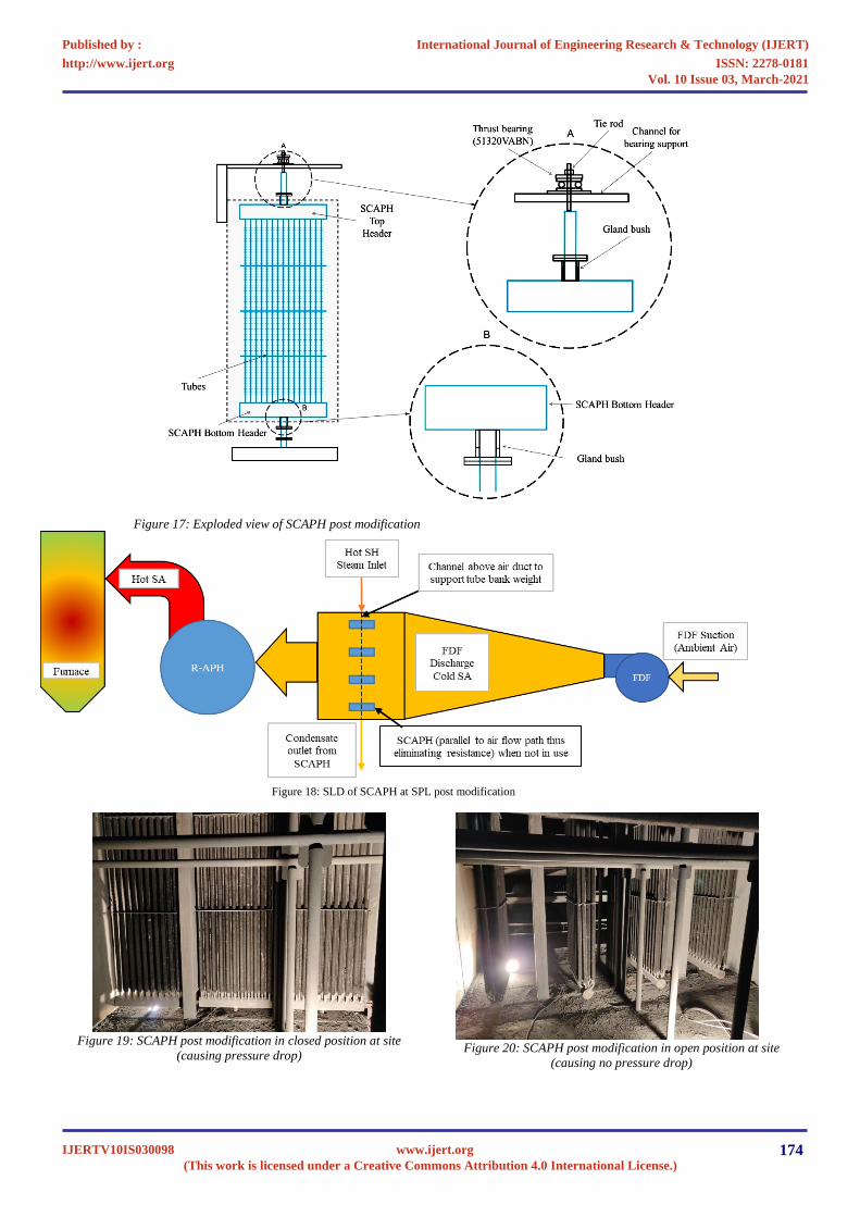
Figure 17: Exploded view of SCAPH post modification
Figure 19: SCAPH post modification in closed position at site
(causing pressure drop)
Figure 20: SCAPH post modification in open position at site
(causing no pressure drop)
Figure 18: SLD of SCAPH at SPL post modification
International Journal of Engineering Research & Technology (IJERT)
ISSN: 2278-0181http://www.ijert.org
IJERTV10IS030098(This work is licensed under a Creative Commons Attribution 4.0 International License.)
Published by :
www.ijert.org
Vol. 10 Issue 03, March-2021
174

C. Timeline and Cost of the Modification:
During planned shutdown of the units at SPL separate
workforce was allocated for this project and the
completion was successfully executed within 6 days of
the overhauling (including the time of material
expedition, material lifting, erection and final completion
of the project activity). The whole cost involved in this
design implementation for both the SCAPHs was
approximately INR 1.50 lakhs only.
D. Cost Benefit Analysis:
The key driving force of any engineering design is the cost
involved in executing it. If the cost involved or the payback
time of the project is huge then the sustainability of the
project becomes questionable. Moreover, the project site
is selling power across India at the cheapest price so this
innovative engineering design and modification had to be
carried out at the lowest cost possible. The benefits
envisaged from the implemented modification are
tabulated in Table – 2. At 670MW load, same coal flow
and same secondary air flow the forced draft fan A and B
current cumulatively decreased by nearly 5.88 amperes
which amounts to a saving of 46.2 kilowatt hour for the 3.3
kilovolt drive at a power factor of nearly 0.9 at site.
Considering the average electricity tariff in India to be INR
3.50 per kilowatt hour then the amount for the electricity
saved can be calculated to be nearly INR 14.16 lakh per
annum. The payback period will be very miniscule and it
can be calculated by dividing the project cost by the benefit
amount derived which evaluates to less than two months.
This profit is derived by pumping more electrical power,
called NESO into the grid for the same amount of
generation.
Table 2: Cost Benefit Analysis prior & post modification
Particulars UOM Before SCAPH
Modification
After SCAPH
Modification
Change
(Δ)
Load MW 670 670.1 0.1
Coal Flow TPH 382 382.8 -0.8
Air flow TPH 1663 1661.5 1.5
FD Fan A current ampere 157.1 154.1 2.98
FD Fan B current ampere 158.0 155.1 2.90
Secondary Air discharge pressure (A Side) mmwc 191.0 174.3 16.7
Secondary Air discharge pressure (B Side) mmwc 192.1 173.9 18.2
Actual Power Consumption of both FD
Fans (Local measurement)
kW 1606 1560 46.2
IV. CONCLUSION:
Through this pioneering implementation of Rotary
SCAPH the units are running healthy and there are no
issues from the operational side since its inception.
Maintenance post modification is also nil. During unit
light up post tripping we take the rotary modified SCAPH
into service and post unit synchronization we rotate the
SCAPH by 90 degrees parallel to air flow path to nullify
the pressure drop across it. This modification has reduced
the auxiliary power consumption through decrease in
forced draft fan loading.
This redesigning of SCAPH is first of its kind in India and
abroad and has been in successful operation ever since the
in-house retrofitting at SPL. The re-engineered Rotary
SCAPH provides measurable and acceptable returns on
investments and serves all its normal functionality as well
as it has been a contributor to efficient fossil-fueled power
generation. We have brought up a new concept of this
often forgotten plant auxiliary to retain its value both on
and off its operation.
V. ACKNOWLEDGEMENT
We extend our heartfelt gratitude to the extraordinary
support which we have received from the top management
at Sasan Power Limited with special mention to Mr. Anil
Kumar Singh (CEO) and Mr. Sachin Mohapatra (Station
Director).
We are thankful to the Rotary parts Mechanical
Maintenance team and to all the skilled and unskilled
manpower that were deployed for the systematic and
planned project implementation.
VI. WAY FORWARD
Through this technical implementation all the thermal
power stations equipped with this type of SCAPH system
arrangement would be benefitted. We are open for
discussion about all intricate details of this project with
interested parties.
VII. ABBREVIATIONS
APC – Auxiliary Power Consumption
APH – Air Pre-Heater
BMCR – Boiler Maximum Continuous Rating
°C – degree Centigrade
Co. – Company
CEO – Chief Executive Officer
FDF – Forced Draft Fan
kg – kilogram
kW – kilowatt
International Journal of Engineering Research & Technology (IJERT)
ISSN: 2278-0181http://www.ijert.org
IJERTV10IS030098(This work is licensed under a Creative Commons Attribution 4.0 International License.)
Published by :
www.ijert.org
Vol. 10 Issue 03, March-2021
175
MT – Metric Ton
MW – Megawatt
NESO – Net Energy Sent Out
Pa – Pascal
RPM – revolutions per minute
SA – Secondary Air
SCAPH – Steam Coil Air Pre-Heater
SH – Superheated
SLD – Single Line Diagram
SS – Stainless steel
TMCR – Turbine Maximum Continuous Rating
TPH – Ton per hour
UOM – Unit of Measurement
VIII. REFERENCES [1] https://www.rotor.lublin.pl/en/research-and-development/rotary-air-
preheater-elements/heating-baskets
[2] https://en.citizendium.org/wiki/Acid_dew_point
International Journal of Engineering Research & Technology (IJERT)
ISSN: 2278-0181http://www.ijert.org
IJERTV10IS030098(This work is licensed under a Creative Commons Attribution 4.0 International License.)
Published by :
www.ijert.org
Vol. 10 Issue 03, March-2021
176
Recommended