Design and Implementation of a Broadcast
Server for the 5G Network Architecture
Author: Alonso Lazarte Montes
Director 1: José Francisco Monserrat del Río
Director 2: David Gómez-Barquero
Director 3: Carlos Barjau Estevan
Start Date: 17/04/2018
Department: Mobile Communications Group (MCG) of iTEAM

1 Design and Implementation of a Broadcast Server for the 5G Network Architecture
Objective
The objective of this Master´s Thesis is to design and implement a Broadcast/Multicast Service Center (BM-
SC) under the framework of the 5G core network; which aims to deliver broadcast services by using the
cellular network. Note that Broadcast and Multicast services are not considered inside the 3rd
Generation
Partnership Project (3GPP) release 15, only the technical specifications to provide Point-To-Point (PTP)
services are described, so the proposal design in this work might be used as reference for future releases of
3GPP where the Point-To-Multipoint (PTM) services are covered.
Methodology
First, the BM-SC and its interfaces described in 3GPP Release 14 (4G eNTV) were implemented; then, based
on that simulator, changes were applied in order to comply with 3GPP Release 15 (5G) as much as it is
specified at the time this work is developed.
Theoretical proposal
As the 3GPP release 15 only considers PTP services, the 5G-XCast project, leaded by the Mobile
Communications Group (MCG) of iTEAM-UPV, is researching how to provide PTM functions over 5G
networks for multimedia, entertainment, automotive, Internet of Things (IoT) and Public Warning Services
(PWS) use cases. Additionally, 5G-XCast project also evaluates the 5G spectrum allocation in order to
deploy those services.
Laboratory work
Java language is used to implement the BM-SC which complies with 4G LTE. The interface between the
BM-SC and the Gateway towards to the access network has a control plane interface (SG-mb) using
DIAMETER as application protocol for signaling purpose and a user plane interface (SGi-mb) using the
MBMS synchronization protocol (SYNC) which encapsulates the user plane data (FLUTE, DASH, etc.).
Next, in order to adapt these interfaces to 5G, the control plane signaling has been implemented over
HTTP/2, while we propose to keep using SYNC protocol for the user plane data.
Results
The results of the simulation show that the control plane complies with the HTTP/2 standard, in this case a
text file is created and we can verify the structure of the header and body of the signaling message. For the
user plane, a binary file is created and then verified the compliance of the SYNC protocol headers by using
the open source tool Wireshark.
Future work
We have simulated the start, update and stop procedures for a PTM session using 5G core network compliant
interfaces. However, we can extend this stand-alone simulation environment into a more complex scenario
by configuring the interface with an external server, such as “Content Provider” simulator via xMB standard
interface in order to test a more sophisticated and realistic test case. Also, this simulator can be integrated
with other platforms such as Open Air Interface and Open5GCore.
Design and Implementation of a Broadcast Server for the 5G Network Architecture 2
Abstract
Cellular PTM solutions are standardized since 3GPP Releases 09 to 14 for 4G technology, known as
enhanced Multimedia Broadcast/Multicast Service (eMBMS). Recently, in the new 3GPP Release 15 for 5G
technology, PTM solutions are not yet standardized but it will be covered in future releases (Release 17).
The main element on the Core Network for the eMBMS service is the Broadcast/Multicast Service Center
(BM-SC) which is in charge to establish the sessions, the entry point of the broadcast traffic and other
functions. In this Master´s Thesis we will design and implement the BM-SC for the 5G network architecture
based on the proposal taken from the 5G-XCast European research project.
The software has been programmed using Java. It is tasked with the management of PTM sessions (Start,
Update and Stop) by creating a text file, which contains the header and body of the HTTP/2 protocol for the
control plane interface, and a binary file, which contains the header and payload of the SYNC protocol for
the user plane interface. To validate the platform, the files have been checked through the protocol analyzer
Wireshark.
Finally, the test results and conclusions of the simulations are presented, including the future works.
Author: Alonso Lazarte Montes, email: [email protected]
Director 1: José Francisco Monserrat del Río, email: [email protected]
Director 2: David Gómez-Barquero, email: [email protected]
Director 3: Carlos Barjau Estevan, email: [email protected]
Derivable Date: 07-09-18
3 Design and Implementation of a Broadcast Server for the 5G Network Architecture
INDEX
I. INTRODUCTION ....................................................................................................... 4
II. ENHANCED MULTIMEDIA BROADCAST/MULTICAST SERVICE
(eMBMS) .............................................................................................................................. 5
II.1. NETWORK ARCHITECTURE ............................................................................. 7
II.2. INTERFACES ........................................................................................................ 8
II.2.1. SG-MB INTERFACE ..................................................................................... 9
II.2.2. SGI-MB INTERFACE .................................................................................... 9
II.3. BROADCAST/MULTICAST SERVICE CENTER (BM-SC) ............................ 10
III. CORE NETWORK ARCHITECTURE IN 5G NETWORK ................................ 13
III.1. NETWORK ARCHITECTURE ....................................................................... 13
III.2. INTERFACES ................................................................................................... 15
III.2.1. NSMF/N4 INTERFACE ............................................................................ 16
III.2.2. N6 INTERFACE ........................................................................................ 16
IV. DESIGN OF BM-SC SERVER FOR 5G NETWORK .......................................... 16
IV.1. BMSC NETWORK FUNCTION ..................................................................... 17
IV.2. BM-SC CONTROL PLANE FUNCTION (BMSC-CPF) ................................ 17
IV.3. BM-SC USER PLANE FUNCTION (BMSC-UPF) ......................................... 19
V. IMPLEMENTATION OF BM-SC SERVER FOR 5G NETWORK ................... 19
V.1. SOFTWARE STRUCTURE ................................................................................. 20
V.2. 5G BM-SC SIMULATION .................................................................................. 21
VI. RESULTS ................................................................................................................... 23
VII. CONCLUSIONS ........................................................................................................ 26
ACKNOWLEDGEMENTS .............................................................................................. 26
REFERENCES .................................................................................................................. 26
ANNEX – A: SESSION CLASS CODE .......................................................................... 27
ANNEX – B: USER PLANE CLASS CODE .................................................................. 31
ANNEX – C: SESSION MANAGEMENT 5G CLASS CODE ..................................... 32
ANNEX – D: 5G BM-SC SIMULATOR FLOW DIAGRAM ....................................... 35

Design and Implementation of a Broadcast Server for the 5G Network Architecture 4
I. INTRODUCTION
Because of the evolution of the mobile networks from 2G to the new incoming 5G, mobile data
services have increased, both in data volume and revenue. The common type of offered services is
a Point-To-Point (PTP) scheme and bidirectional communication, also known as unicast, where
each user has access to the network and, therefore, all the services the user is subscribed to.
On the other hand, Point-To-Multipoint (PTM) communications allow not only transmission of
linear television services as digital terrestrial television (DVB-T in Europe, ATSC in USA, ISDB-T
in Japan and South America) where it does not require any subscription, but new use-cases such as
machine-type and vehicular communications among others. We can mention the following
advantages respect to the PTP communications:
Efficient use of the network resources to deliver the same content to a several number of users
in a specific geographical area, which could be ranging from cell coverage to wide nation
coverage.
Improve the quality of reception on the edge coverage due to many cells can cover that zone so
the terminal can receive the signal from all those cells in the same frequency. This scenario is
called Single Frequency Network (SFN) operation.
An early cellular PTM service called “Cell Broadcast Service (CBS) was defined in the GSM
technology, which allows sending text messages, as known as Short Message Service (SNS), to
specific areas. As an old technology, the bitrate assigned to this service was very low suitable only
for SMS; however, it is still used nowadays for Public Warning Services (PWS). Then, the 3rd
Generation Partnership Project (3GPP) introduced, in the Release 6 for the existing 3G systems, the
PTM service called “Multimedia Broadcast/Multicast Service” (MBMS). This solution added a
new element into the core network, the Broadcast Multicast Service Center (BM-SC). Many of the
signaling and concepts carried to future Releases were introduced here. Even though MBMS was
defined, it did not success commercially due to the low capacity over the radio interface to support
multimedia content delivery.
As the technology improved, new enhancements are included in the mobile network which
leads to the 4G where the Long Term Evolution (LTE) is the main representative technology. The
main improvements on the core network side is that all IP-based network an initial separation
between the control and user plane, while the Air Interface uses OFDM which allows greater
bitrates than 3G. Regarding PTM communications, based on the previous MBMS standard, 3GPP
standardized the enhanced MBMS (eMBMS) for LTE in the Release 9. Since that Release, new
features and mechanisms are added through the way to the latest Release 14.
Now, the 5G technology is being developed and standardized so the technical specifications
should be released at the end of 2017 as part of the 3GPP Release 15, also known as Phase 1. This
Phase 1 was mostly focused on the new Air Interface, named New Radio or NR. This technology
5 Design and Implementation of a Broadcast Server for the 5G Network Architecture
will be presented to International Mobile Telecommunication 2020 (IMT-2020) evaluation, to
cover the “Mobile Broadband” category.
Regarding the 5G core specification, it is plan to be finished by the end of 2018. The new
concepts introduced in Release 15 are the use Network Functions and the introduction of Network
Slicing. Together, these concepts allow developing new services with different requirements, while
keeping the Control and User Plane Separation (CUPS) introduced in Release 14.
As previously mentioned, this first phase is focused on the Mobile Broadband, which means
that the type of communications targeted are the PTP communications. However, as we can see
during the evolution of the mobile network, the multicast/broadcast will be eventually standardized
as MBMS/eMBMS were. It is expected that this process takes place in Release 17. Meanwhile; the
5G-XCast European Project [1], leaded by the Mobile Communications Group (MCG) of iTEAM-
UPV, is working on the proposal for PTM communications scenario based on the network
architecture and procedures described on the Release 15. 5G-Xcast is part of the 5G Public-Private
Partner (5GPP) framework, which is a 5G research program aims to deliver solution, architectures
and standards for 5G networks and the IMT-2020, which is responsible to define the requirements
the technologies need to comply in order to be called 5G technology.
This Master Thesis is focused on studying and implementing a proposed architecture of the
BM-SC for the 5G network architecture based on the current 4G eMBMS solution and 5G-Xcast
proposals, alongside the ongoing standardization of the 3GPP Release 15. The software will
manage the broadcast session (control plane functions) by creating text files for each procedure and
then creates a binary file (user plane functions) that contains the payload. Both files will comply
with the standards defined by the 3GPP Release 15.
The content is distributed as follows. Section 2 describes the eMBMS architecture, including the
main concepts focusing on the BM-SC and its interfaces. Section 3 contains the description of the
5G core network architecture, main network functions and a deeper description of the interfaces
related to MBMS. In section 4, we will describe the proposed network architecture for MBMS, the
new network functions and interfaces for control and user plane. Section 5 will detail the diagram
flow of the simulator. Section 6 will show the results of the simulator for 4G and 5G systems and
finally, section 7 will summarize the main conclusions and observations.
II. ENHANCED MULTIMEDIA BROADCAST/MULTICAST SERVICE
(eMBMS)
As an evolution of the MBMS, introduced in Release 6 for the Universal Mobile
Telecommunications System (UMTS), the eMBMS was specified for Long Term Evolution (LTE)
systems as part of the Release 9 bringing a set of improvements e.g. better data rate due to the
Orthogonal Frequency Division Multiplexing (OFDM) at radio physical layer, the MBMS Single
Frequency Network (MBSFN) is the area covered by many eNodeBs to deliver the same content, at
Design and Implementation of a Broadcast Server for the 5G Network Architecture 6
the same time and at the same frequency so the cells should be synchronized which means that the
MBMS signal is no longer disruptive but constructive.
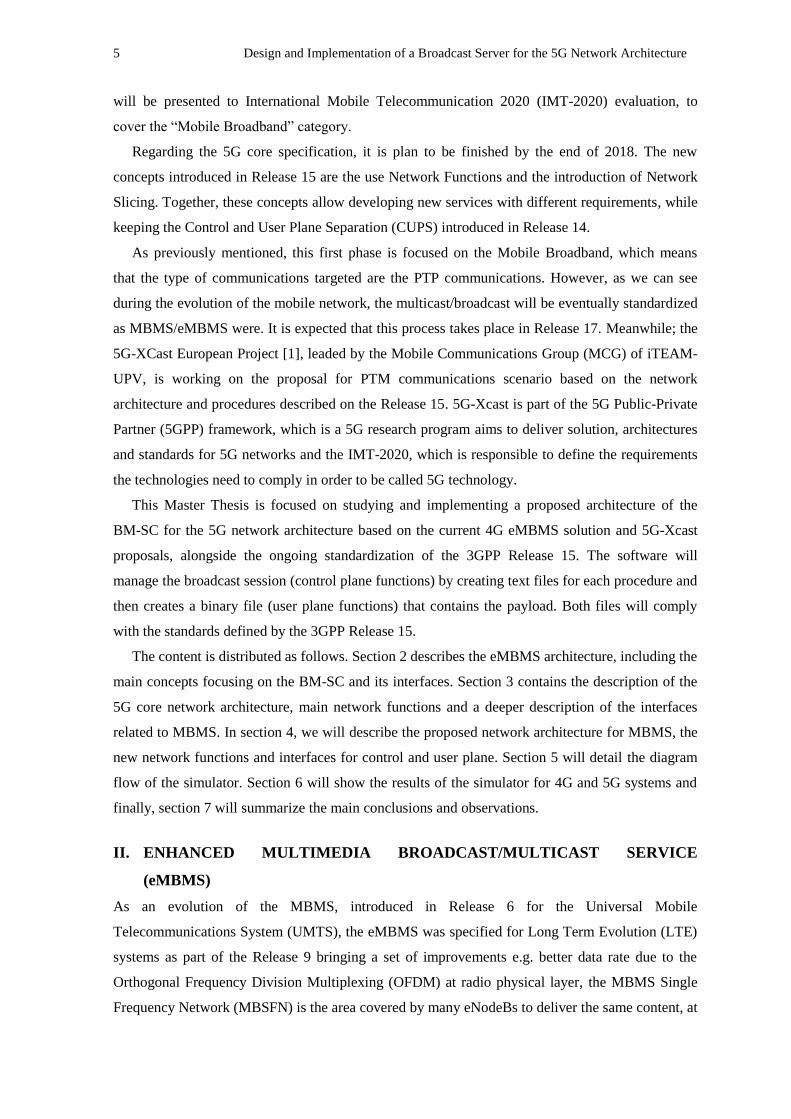
Following, we will describe the main enhancements that each Release added into the eMBMS.
Release 10: Introduced a mechanism in the access network in order to count the number of users
interested in MBMS service.
Release 11: Introduced video codec for higher resolutions and forward error correction, by
using Raptor codes. In addition, we can mention the service continuity in multi-frequency
scenarios where the users can do a quick handover between carriers.
Release 12: Introduced an amazing enhancement called MBMS operation on Demand (MooD)
which allows the seamless transition from unicast to broadcast mode depending on the number
of users that request specific content. In this way, the network can decide whether a PTP is
better than a PTM sessions or not.
Release 13: Introduced Single-Cell PTM (SC-PTM) feature which allows one cell to broadcast
the content to several users by multiplexing the broadcast and unicast information on the same
channel (Physical Downlink Shared Channel – PDSCH) instead of using a dedicated physical
channel for the broadcast service.
Release 14: enTV brought several enhancements: In the radio interface, eMBMS will support
larger Inter-Site Distance (ISD) by enlarger the Cyclic Prefix (CP), new MBSFN subframe,
enable the possibility to send mixed unicast and broadcast services over a single carrier. Due to
these enhancements, Release 14 is not backwards compatible with the previous releases so the
user equipments should be upgraded too. Interesting changes are also the addition of the
Receive-only mode (ROM) which allows the devices without a SIM card (TV set, tables, etc.)
to receive the eMBMS data; as a consequence, free-to-air services (like public broadcasting) can
be delivered through the eMBMS. It also standardizes the interface between the BM-SC and the
Content Provider, this new interface is known as xMB-C (Control plane) and xMB-U (User
plane). Finally, this release introduced SC-PTM for V2X (vehicle to everything), SC-PTM for
IoT (Internet of Things) and NB-IoT (NarrowBand IoT).
Fig.1. Timeline evolution of eMBMS [2].
7 Design and Implementation of a Broadcast Server for the 5G Network Architecture
II.1. NETWORK ARCHITECTURE
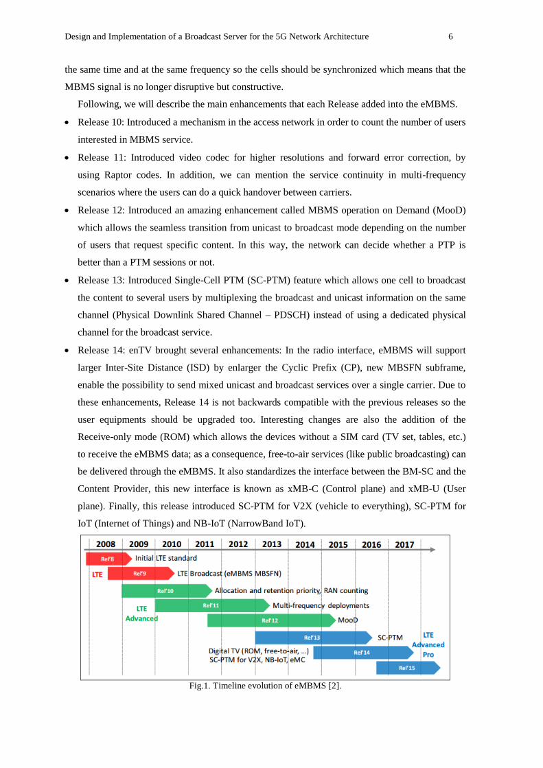
In this section, we will describe the network architecture of eMBMS including the network
elements introduced in the Release 9 for this service.
Fig.2. eMBMS network architecture.
Firstly, we will mention and briefly describe the network elements related to traditional unicast
service provided by LTE:
Evolved NodeB (eNodeB): It is the element that handles the air interface between the user and
the Evolved Packet Core (EPC). Unlike the NodeB from UMTS, it does not need a radio
controller so it is directly connected to the EPC.
Mobility Management Entity (MME): It handles the mobility management of the users, also the
access and security during the registration procedure. It is the control node on the EPC.
Home Subscriber Server (HSS): It is the element that serves as an authenticator for the LTE
users. It is the database of all LTE users and storages information like authentication keys,
Access Point Name (APN), the Radio Technology Access (RAT) type.
Serving Gateway (SGW): It routes and forwards the user plane data and serves as an anchor
during the handover intra-LTE or handover to other 3GPP technologies.
Packet Date Network Gateway (PGW): It is the element that provides connectivity to external
networks; such as Internet, private enterprise networks, IMS, etc. It also is the anchor between
3GPP networks and non-3GPP networks. One important function is that it can allocate the IP
address to the users.
In order to provide the eMBMS service, three new elements were added into the network
architecture of LTE:
Broadcast/Multicast Service Center (BM-SC): It is the entry point of the MBMS content from
the content providers. It manages the MBMS sessions (start, update and stop), controls the
eMBMS carriers, service announcements and provide security of the sessions. As this Master´s
Design and Implementation of a Broadcast Server for the 5G Network Architecture 8
Thesis is focused on the design and implementation of the BM-SC for 5G, more detailed
explanation will be provided in section II.3.
MBMS Gateway (MBMS-GW): It distributes the MBMS data to the eNodeBs (eNBs) that
covers the broadcast area. It communicates with the MME to exchange signaling messages for
establishing the MBMS bearer. In addition, this node manages the IP multicast group where the
eNBs should join when a MBMS session will be established.
Multi-cell/multicast Coordination Entity (MCE): This node handles the radio resource
allocation and the coordination of the MBSFN and SC-PTM transmissions. It decides the
codification and modulation schemes that guarantees the service and also whether setup or not
the eMBMS bearer depending on the available resource on the cells. This entity can be built-in
in the same eNodeB, which is called MCE distributed architecture, or as a stand-alone node to
control several eNodeB, called MCE centralized architecture.
II.2. INTERFACES
In this section, a brief description of the eMBMS interfaces will be described, in subsections II.2.1
and II.2.2 we will cover with more details the interfaces SG-mb and SGi-mb due to BM-SC uses
them.
M1 interface: It is the interface between MBMS-GW and eNodeBs used for MBMS user plane.
IP Multicast is used on this interface. It is based on GTPv1-U as the application layer.
Additionally, the MBMS synchronization protocol (SYNC protocol) [X] is encapsulated over
this interface and it is used between BM-SC and the eNodeB to keep the content
synchronization for MBMS service data transmission
M2 interface: It is the interface between eNodeB and the MCE and used for signaling
transmission. The application protocol is the M2 Application Part (M2AP) protocol.
M3 interface: It is the interface between the MCE and the MME and used, as M2 interface, for
signaling transmission for starting, updating or stopping a MBMS session among another
functions. The application protocol is the M3 Application Part (M3AP) protocol.
Sm interface: It is the control plane interface between MME and MBMS-GW, also used for
session management purpose. The application protocol over this interface is GTPv2-C.
SG-mb interface: It is the interface for control plane between MBMS-GW and BM-SC. The
application protocol over this interface is DIAMETER.
SGi-mb interface: It is the interface for user plane between MBMS-GW and BM-SC. The
application protocol over this interface is sent over the SYNC protocol.
xMB interface: It is the interface between BM-SC and the Content Provider. It is divided in the
control plane (xMB-C) and user plane (xMB-U). The application protocol over this interface is
Hypertext Transfer Protocol (HTTP).
9 Design and Implementation of a Broadcast Server for the 5G Network Architecture
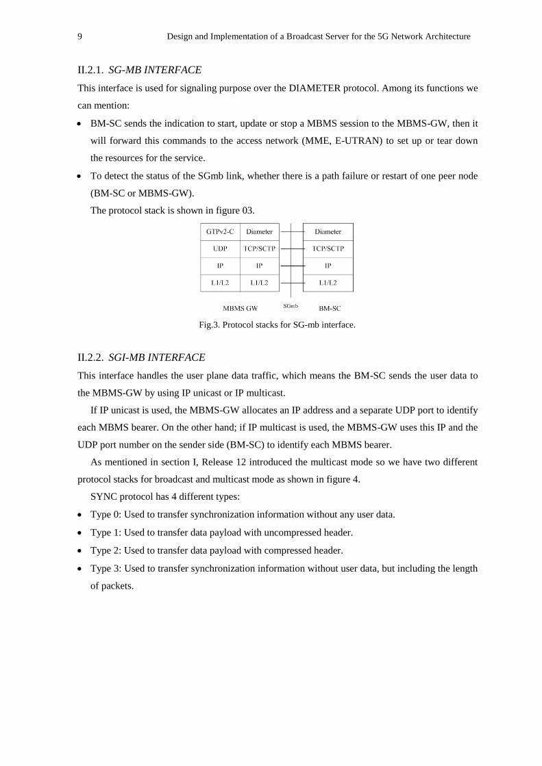
II.2.1. SG-MB INTERFACE
This interface is used for signaling purpose over the DIAMETER protocol. Among its functions we
can mention:
BM-SC sends the indication to start, update or stop a MBMS session to the MBMS-GW, then it
will forward this commands to the access network (MME, E-UTRAN) to set up or tear down
the resources for the service.
To detect the status of the SGmb link, whether there is a path failure or restart of one peer node
(BM-SC or MBMS-GW).
The protocol stack is shown in figure 03.
Fig.3. Protocol stacks for SG-mb interface.
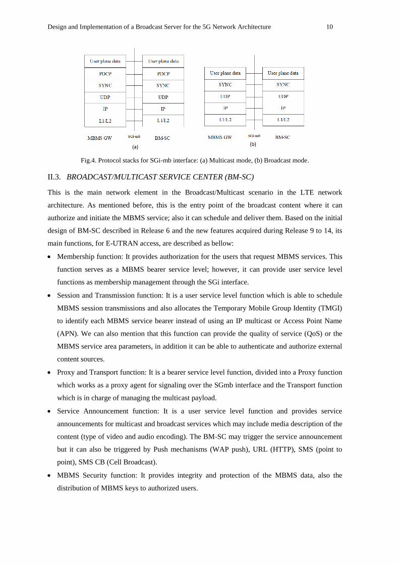
II.2.2. SGI-MB INTERFACE
This interface handles the user plane data traffic, which means the BM-SC sends the user data to
the MBMS-GW by using IP unicast or IP multicast.
If IP unicast is used, the MBMS-GW allocates an IP address and a separate UDP port to identify
each MBMS bearer. On the other hand; if IP multicast is used, the MBMS-GW uses this IP and the
UDP port number on the sender side (BM-SC) to identify each MBMS bearer.
As mentioned in section I, Release 12 introduced the multicast mode so we have two different
protocol stacks for broadcast and multicast mode as shown in figure 4.
SYNC protocol has 4 different types:
Type 0: Used to transfer synchronization information without any user data.
Type 1: Used to transfer data payload with uncompressed header.
Type 2: Used to transfer data payload with compressed header.
Type 3: Used to transfer synchronization information without user data, but including the length
of packets.
Design and Implementation of a Broadcast Server for the 5G Network Architecture 10
Fig.4. Protocol stacks for SGi-mb interface: (a) Multicast mode, (b) Broadcast mode.
II.3. BROADCAST/MULTICAST SERVICE CENTER (BM-SC)
This is the main network element in the Broadcast/Multicast scenario in the LTE network
architecture. As mentioned before, this is the entry point of the broadcast content where it can
authorize and initiate the MBMS service; also it can schedule and deliver them. Based on the initial
design of BM-SC described in Release 6 and the new features acquired during Release 9 to 14, its
main functions, for E-UTRAN access, are described as bellow:
Membership function: It provides authorization for the users that request MBMS services. This
function serves as a MBMS bearer service level; however, it can provide user service level
functions as membership management through the SGi interface.
Session and Transmission function: It is a user service level function which is able to schedule
MBMS session transmissions and also allocates the Temporary Mobile Group Identity (TMGI)
to identify each MBMS service bearer instead of using an IP multicast or Access Point Name
(APN). We can also mention that this function can provide the quality of service (QoS) or the
MBMS service area parameters, in addition it can be able to authenticate and authorize external
content sources.
Proxy and Transport function: It is a bearer service level function, divided into a Proxy function
which works as a proxy agent for signaling over the SGmb interface and the Transport function
which is in charge of managing the multicast payload.
Service Announcement function: It is a user service level function and provides service
announcements for multicast and broadcast services which may include media description of the
content (type of video and audio encoding). The BM-SC may trigger the service announcement
but it can also be triggered by Push mechanisms (WAP push), URL (HTTP), SMS (point to
point), SMS CB (Cell Broadcast).
MBMS Security function: It provides integrity and protection of the MBMS data, also the
distribution of MBMS keys to authorized users.
11 Design and Implementation of a Broadcast Server for the 5G Network Architecture
Now, we will describe the MBMS procedures initiated by the BM-SC, these procedures include
the “Session Start”, “Session Update” and “Session Stop” for the MBMS sessions. During the
signaling flow between BM-SC and the MBMS-GW, the DIAMETER protocol is used in the
SGmb interface as we mentioned in the previous section.
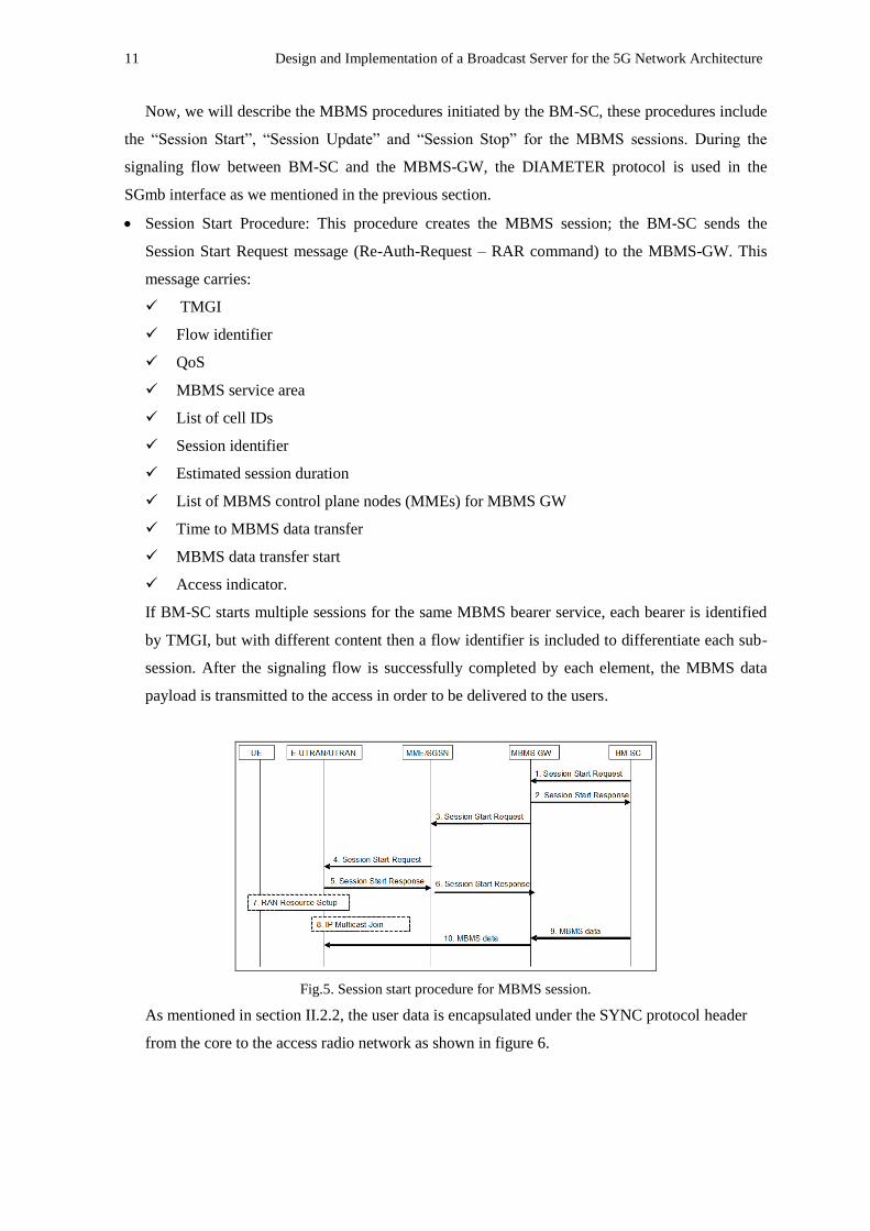
Session Start Procedure: This procedure creates the MBMS session; the BM-SC sends the
Session Start Request message (Re-Auth-Request – RAR command) to the MBMS-GW. This
message carries:
TMGI
Flow identifier
QoS
MBMS service area
List of cell IDs
Session identifier
Estimated session duration
List of MBMS control plane nodes (MMEs) for MBMS GW
Time to MBMS data transfer
MBMS data transfer start
Access indicator.
If BM-SC starts multiple sessions for the same MBMS bearer service, each bearer is identified
by TMGI, but with different content then a flow identifier is included to differentiate each sub-
session. After the signaling flow is successfully completed by each element, the MBMS data
payload is transmitted to the access in order to be delivered to the users.
Fig.5. Session start procedure for MBMS session.
As mentioned in section II.2.2, the user data is encapsulated under the SYNC protocol header
from the core to the access radio network as shown in figure 6.
Design and Implementation of a Broadcast Server for the 5G Network Architecture 12
Fig.6. User data payload encapsulation [3]
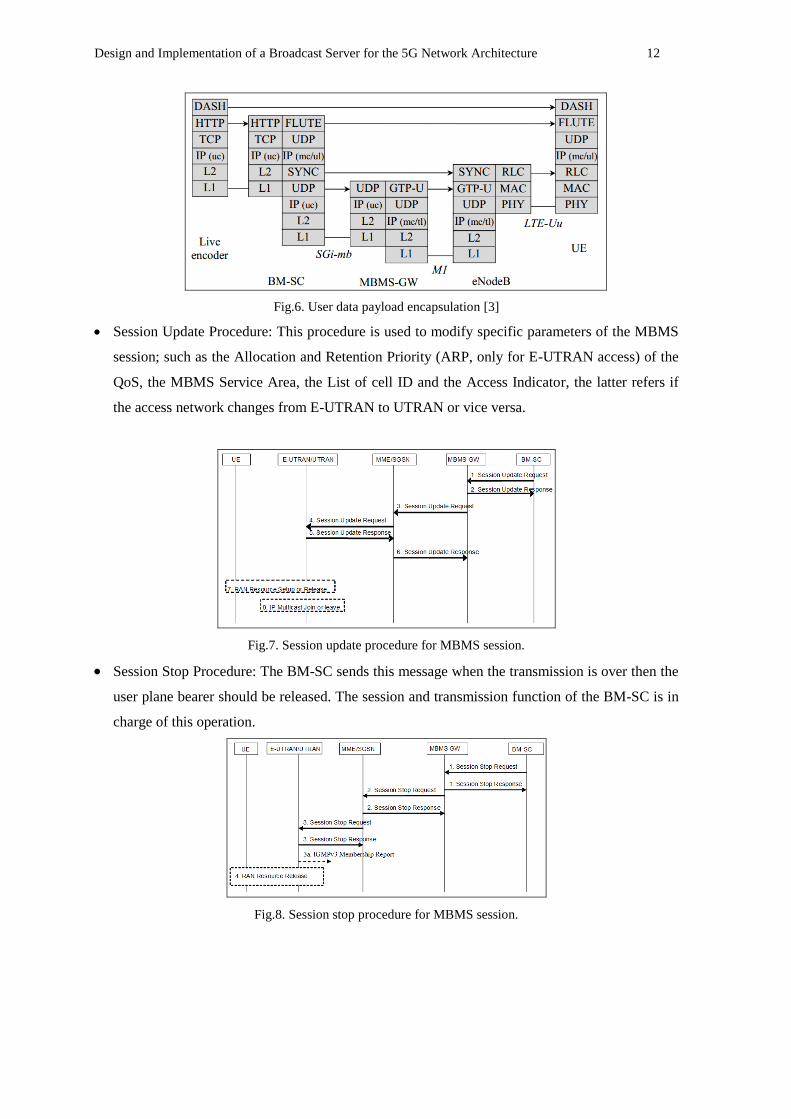
Session Update Procedure: This procedure is used to modify specific parameters of the MBMS
session; such as the Allocation and Retention Priority (ARP, only for E-UTRAN access) of the
QoS, the MBMS Service Area, the List of cell ID and the Access Indicator, the latter refers if
the access network changes from E-UTRAN to UTRAN or vice versa.
Fig.7. Session update procedure for MBMS session.
Session Stop Procedure: The BM-SC sends this message when the transmission is over then the
user plane bearer should be released. The session and transmission function of the BM-SC is in
charge of this operation.
Fig.8. Session stop procedure for MBMS session.
13 Design and Implementation of a Broadcast Server for the 5G Network Architecture
III. CORE NETWORK ARCHITECTURE IN 5G NETWORK
In this section we will describe the main concepts related to the 5G Network and its main use
cases. Then we will resume the network architecture of 5G Core Network based on the ongoing
standardization process made by the 3GPP [4] so far until the development of this Master Thesis.
Software-Defined Networking (SDN): The SDN architecture refers to the scenario where the
user (Service consumer) exchanges the control and user plane with the server (SDN Controller)
in order to request services. The controller can forward the user plane to a group of external
resources or manage them by its own resources, in this way the controller virtualizes and
orchestrates the resources. This networking architecture includes the sharing and flexible
distribution of the resources.
Network Functions Virtualization (NFV): It is a network architecture concept which also
defines a decoupling process for the network functions (Like firewalls, mobile core network
elements, network address translation, etc.) from the hardware infrastructure. This means that
the element functions can run as software over any hardware, unlike the legacy network
architecture where each network element is deployed in specific hardware for specific functions.
Network Slicing: It can be considered as a combination of SDN and NFV because it refers to
the capability of the network to be divided into independent and isolated “Virtual Networks” to
support different kind of services over the same network infrastructure. In other words, each
Network Slice is tailored for different requirements, depending on the service, in order to fulfill
them. This concept will be clarified with the description of the use cases for 5G Network.
Use cases: The International Telecommunication Union (ITU) International Mobile
Telecommunication (IMT – 2020) defines three use cases for the IMT-2020 which are:
enhanced Mobile Broadband (eMBB), Ultra-Reliable Low Latency Communication (UR-LLC)
and massive Machine-Type Communication (mMTC). These cases requirements can be fulfilled
by using the network slicing concept. 5G network will be able to support each type of service
under the same physical infrastructure by virtualizing and isolating networks.
III.1. NETWORK ARCHITECTURE
As mentioned in the previous section, the 5G architecture is based on SDN and NFV. Different
benefits are gained, which are listed here:
The control plane (CP) and user plane (UP) is separately deployed. This allows greater
scalability (Compared with the gateways SGW/PGW in the LTE architecture).
Reduce the dependency between the access network and the core network, which means the
core network can be integrated with different access networks e.g. 3GPP and non.3GPPP
access.
Design and Implementation of a Broadcast Server for the 5G Network Architecture 14
Network Functions can interact directly between themselves. In this way, there is no need to use
Diameter Routing Agents (DRA) or Signal Transfer Point (STP) as used in LTE and
UMTS/GPRS respectively.
The User Plane functions can be deployed near to the access network in order to guarantee low
latency requirements for specific services.
The new paradigm adopted for 5G systems includes also that the network elements (NE), e.g.
MME, SGW, PGW, HSS, etc. for LTE, are now described as software Network Functions (NF)
based on the NFV concept. In this way, the core network will have different NF for different
functions (Mobility management, session management, authentication, policy, etc.), in plain words
the NE will be replaced by NF.
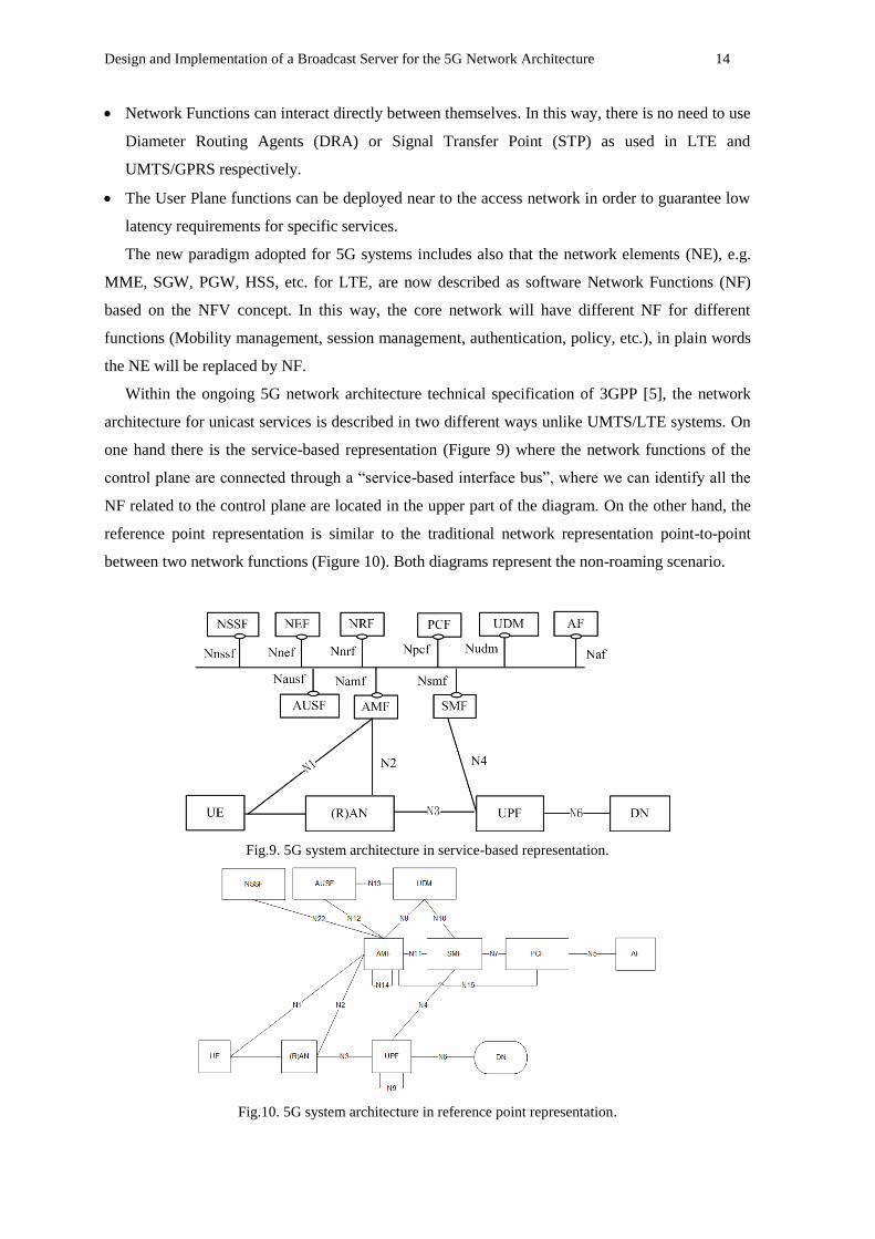
Within the ongoing 5G network architecture technical specification of 3GPP [5], the network
architecture for unicast services is described in two different ways unlike UMTS/LTE systems. On
one hand there is the service-based representation (Figure 9) where the network functions of the
control plane are connected through a “service-based interface bus”, where we can identify all the
NF related to the control plane are located in the upper part of the diagram. On the other hand, the
reference point representation is similar to the traditional network representation point-to-point
between two network functions (Figure 10). Both diagrams represent the non-roaming scenario.
Fig.9. 5G system architecture in service-based representation.
Fig.10. 5G system architecture in reference point representation.
15 Design and Implementation of a Broadcast Server for the 5G Network Architecture
Following, we will describe the main NF and elements related to unicast service which may be part
of the broadcast scenario.
(Radio) Access Network ((R)AN): It is the access network that connects the user with the core,
similar functions as the eNodeB in LTE.
Authentication Server Function (AUSF): Acts as an authenticator server, similar to the function
that HSS has in LTE system.
Access and Mobility Management Function (AMF): It supports registration management,
mobility management, access authentication, access authorization, location services
management for regulatory services. It performs the functions of the MME in LTE system.
Network Slice Selection Function (NSSF): Network slicing is a key concept in the 5G
technology, this network function decides which Network Slice Instance will serve to the user
based on the type of required service then it will select the proper AMF for that service.
Session Management Function (SMF): It handles the session management, IP address allocation
for the user, traffic steering. Similar functions that MME and PGW has in LTE.
User Plane Function (UPF): It routes and forwards the packets, packet inspection, QoS handling
and interconnection with external networks (Data Networks). Similar functions as SGW and
PGW in LTE.
Data Network (DN): Any external network that 5G core network connects, it can be internet,
IMS network, private operator network, etc.
III.2. INTERFACES
In this subsection we will describe the main interfaces of the 5G system.
Service Based interface: “Bus interface” that interconnects all the NF of the control plane which
includes Namf, Nsmf, Nudm, Nnrf, Nnssf, Nausf, Nnef, Nsmsf, Nudr, Npcf, N5g-eir, Nlmf. It
uses JavaScript Object Notation (JSON) over HTTP/2[6].
N1 interface: Interface between the user and the AMF. It uses the Non-Access-Stratum
Protocol (NAS) which is used for registration and connection management (Mobility
Management procedures) and Session Management procedures.
N2 interface: Interface between (R)AN and the AMF, it means the control plane between 5G-
Access and 5G Core Network. The application layer protocol is NG Application Protocol (NG-
AP) which runs over SCTP.
N3 interface: Interface between the (R)AN and the UPF which transports the user plane
information encapsulated in GPRS Tunneling Protocol for the user plane (GTP-U), the same
protocol used in UMTS and LTE.
N4 interface: Interface between SMF and UPF, used for creating, modifying and releasing the
user plane sessions. It runs over HTTP/2.

Design and Implementation of a Broadcast Server for the 5G Network Architecture 16
N6 interface: Interface between UPF and DN, used for forwarding the user plane data to/from
external networks such as internet.
III.2.1. NSMF/N4 INTERFACE
The service-base and point representation are depicted in figure 11 (a) while the protocol stack in
figure 11 (b). It uses HTTP/2[7] as application protocol and JavaScript Object Notation (JSON) as
a serialization protocol in order to manage the user plane session. The APIs are cloud friendly and
the industry is very familiar with this protocol.
Fig.11. N4 interface: (a) Point Reference, (b) Protocol Stack
III.2.2. N6 INTERFACE
As mentioned before, the N6 is an external interface; if the PDU session type is IPv4/IPv6 packet
then the PDU layer is IPv4/IPv6, if it is Ethernet Frame so the PDU layer is Ethernet and so on. We
can see the PDU layer will depend on the type of the service. This interface is similar to the Gi/SGi
interface on UMTS/LTE systems. In figure 12 we can see the user plane protocol on all the way
from access to external network.
Fig.12. N4 interface: (a) Point Reference, (b) Protocol Stack
IV. DESIGN OF BM-SC SERVER FOR 5G NETWORK
Based on the BM-SC described in 3GPP for eMBMS service, the new network function will be
split into two sub-functions for control and user plane due to the plane separation concept of the 5G
new core network explained in section III.1. In the following sections, we will describe the network
17 Design and Implementation of a Broadcast Server for the 5G Network Architecture
function description and detail each function. The following BM-SC architecture is proposed by the
5G-XCast project deliverable 4.1 for the Mobile Core Network.
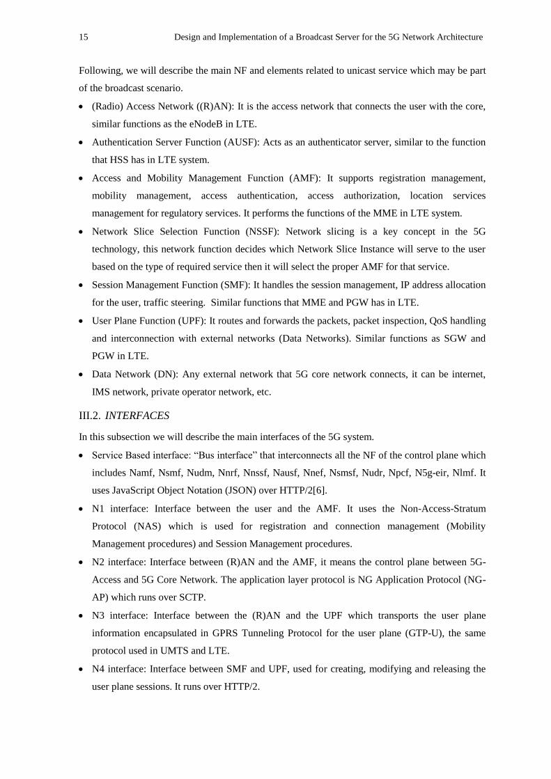
IV.1. BMSC NETWORK FUNCTION
This network function complies with the Control User Plane Separation (CUPS) and also the
modularization of those functions. In figure 13 we can observe the location of the BM-SC in the 5G
network architecture.
Fig.13. BM-SC Network Function
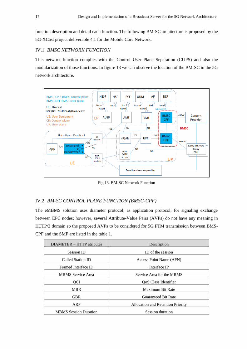
IV.2. BM-SC CONTROL PLANE FUNCTION (BMSC-CPF)
The eMBMS solution uses diameter protocol, as application protocol, for signaling exchange
between EPC nodes; however, several Attribute-Value Pairs (AVPs) do not have any meaning in
HTTP/2 domain so the proposed AVPs to be considered for 5G PTM transmission between BMS-
CPF and the SMF are listed in the table 1.
DIAMETER – HTTP atributes Description
Session ID ID of the session
Called Station ID Access Point Name (APN)
Framed Interface ID Interface IP
MBMS Service Area Service Area for the MBMS
QCI QoS Class Identifier
MBR Maximum Bit Rate
GBR Guaranteed Bit Rate
ARP Allocation and Retention Priority
MBMS Session Duration Session duration
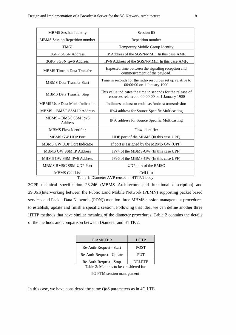
Design and Implementation of a Broadcast Server for the 5G Network Architecture 18
MBMS Session Identity Session ID
MBMS Session Repetition number Repetition number
TMGI Temporary Mobile Group Identity
3GPP SGSN Address IP Address of the SGSN/MME. In this case AMF.
3GPP SGSN Ipv6 Address IPv6 Address of the SGSN/MME. In this case AMF.
MBMS Time to Data Transfer Expected time between the signaling reception and
commencement of the payload.
MBMS Data Transfer Start Time in seconds for the radio resources set up relative to
00:00:00 on 1 January 1900
MBMS Data Transfer Stop This value indicates the time in seconds for the release of
resources relative to 00:00:00 on 1 January 1900
MBMS User Data Mode Indication Indicates unicast or multicast/unicast transmission
MBMS – BMSC SSM IP Address IPv4 address for Source Specific Multicasting
MBMS – BMSC SSM Ipv6
Address IPv6 address for Source Specific Multicasting
MBMS Flow Identifier Flow identifier
MBMS GW UDP Port UDP port of the MBMS (In this case UPF)
MBMS GW UDP Port Indicator If port is assigned by the MBMS GW (UPF)
MBMS GW SSM IP Address IPv4 of the MBMS-GW (In this case UPF)
MBMS GW SSM IPv6 Address IPv6 of the MBMS-GW (In this case UPF)
MBMS BMSC SSM UDP Port UDP port of the BMSC
MBMS Cell List Cell List
Table 1: Diameter AVP reused in HTTP/2 body
3GPP technical specification 23.246 (MBMS Architecture and functional description) and
29.061(Interworking between the Public Land Mobile Network (PLMN) supporting packet based
services and Packet Data Networks (PDN)) mention three MBMS session management procedures
to establish, update and finish a specific session. Following that idea, we can define another three
HTTP methods that have similar meaning of the diameter procedures. Table 2 contains the details
of the methods and comparison between Diameter and HTTP/2.
DIAMETER HTTP
Re-Auth-Request - Start POST
Re-Auth-Request - Update PUT
Re-Auth-Request - Stop DELETE
Table 2: Methods to be considered for
5G PTM session management
In this case, we have considered the same QoS parameters as in 4G LTE.
19 Design and Implementation of a Broadcast Server for the 5G Network Architecture
IV.3. BM-SC USER PLANE FUNCTION (BMSC-UPF)
We consider keeping using SYNC protocol between BMSC-UPF and the UPF as in eMBMS
because of the need to have synchronized the core and the radio access network (RAN). As an
additional proposal, SYNC payload should be encapsulated in GTP protocol to communicate the
UPF and the RAN, the study of that proposal is beyond the scope of this Master Thesis.
As mentioned in section II.2.2, there are four types of SYNC protocol header but we consider
using only type 0 (Only for synchronization) and type 1 (When there is actually payload to deliver).
V. IMPLEMENTATION OF BM-SC SERVER FOR 5G NETWORK
In order to implement the BM-SC in the 5G framework, Java language will be used as the
programming language so it can be easily integrated with external sources in order to make a more
complex test scenario. This work was developed using Java Runtime Environment 1.8.0 and the
Integrated Development Environment is NetBeans IDE 8.2. Currently, the simulations are tested in
an stand-alone scenario by creating text and binary files that represents the control and user plane
messages respectively. However, in future works we can use advanced Java libraries in order to
establish a real IP communication with external elements.
Control plane signaling is represented as a text file which includes all the information shown in
table 1. When a session is started, updated or finished, the simulator will create automatically the
Request and Response HTTP/2 message for each action with the input values that have been given
by the user.
User plane data is represented as a binary file which is encapsulated into the SYNC protocol
type 0 (no payload, only synchronization) or type 1(with actual payload). The payload is the data
that the user gets through the PTM transmission e.g.: streaming media over Dynamic Adaptive
Streaming over HTTP (DASH) protocol, but for didactical purpose the payload used in the
simulator will be text files in order to be decoded by WIRESHARK and validate the data is
correctly encapsulated by the simulator. We have three text files that represent the payload.
Content 01:
HOLA MUNDO!
SALUDOS DESDE LA UPV!
HASTA PRONTO.
Content 02:
UPV 2018!
Content 03:
PTM solution over 5G network architecture.
In the following sections we will describe the main parts of the body program and then the
details we considered for the 5G PTM session management.
Design and Implementation of a Broadcast Server for the 5G Network Architecture 20
V.1. SOFTWARE STRUCTURE
The software has three classes:
Session class: This class has the following variables: Session Name, Session ID, MBMS Service
Area, QoS QCI, QoS MBR, QoS GBR, QoS ARP and TMGI. It has a constructor, 8 GET and
SET methods for each variable. Finally, 3 important methods are defined for each session
management action:
Session start procedure: It uses the 8 variables of the class and we define two directory
paths (String variable which includes the session name) to store the text files for request
and response message. The request file includes the HTTP/2 header for POST method,
including the path, scheme and content-type. The body of this message contains the
information listed in table 1. Let’s notice there are only 8 variables, the rest of the values
are fixed due to this simulation is “stand alone” with no interaction with external sources.
The respond message includes in the header “200 OK” (It is considered that the
connection is good), the path, content type and the body includes the session name and
ID.
Session update procedure: It has the same structure as the request/respond of the start
procedure but with the method used in the HTTP/2 header is PUT instead of POST.
Session stop procedure: Similar to session start procedure but using the DELETE method
in the HTTP/2 header of the request and the “204 No Content” in the respond message.
Java code of this class is shown in Annex A.
UserPlane class: This class has the following variables: Session Name, type of SYNC header
and the directory path where the binary file will be stored. As mentioned before, this simulation
only includes SYNC header type 0 and 1. The former type includes PDU type (0), time stamp,
packet number, elapsed octet counter (0), total number of packet (0), total number of octet (0)
and the Header CRC while the latter type includes PDU type (1), time stamp, packet number,
elapsed octet counter, header CRC and payload CRC. The payload data that will be
encapsulated is a text file so each line of the text file will be considered as one payload frame,
therefore content 01 has 3 frames, content 02 and 03 have only 1 frame.
In addition as we can see the header structure of type 01 in section II.2.2, there are padding bits
when the payload filed is not an exact number of bytes; however, in this simulation we do not
need to use them due to the coding format of the text file is 8-bit Unicode Transformation
Format (UTF-8), which means is coded in 8 bit units.
Java code of this class is shown in Annex B.

21 Design and Implementation of a Broadcast Server for the 5G Network Architecture
Session Management 5G class: This class invokes Session and UserPlane classes. It has the
following variables: Session name, MBMS Service Area, QoS QCI, QoS MBR, QoS GBR, QoS
ARP, TMGI, directory path, SYNC type, array of Session objects and array of UserPlane
objects. The important methods are:
AddSession: This method is used to start a new session including the signaling message
and the user plane data by using the Session and UserPlane class respectively. The input
data required for the new session is session name, session ID, MBMS Service Area, QoS
QCI, QoS MBR, QoS GBR, QoS ARP and TMGI while in the user plane side we can
select type 0 with no payload or type 1 and then select the content (1, 2 or 3).
UpdateSession: This method is used to update an existing session, we need to select the
session and then we can update the MBMS Service Area or ARP based on the 3GPP
technical specification 23.246. It will use the Session class to update the values in the
selected session.
StopSession: This method will delete the selected session. It will invoke the Session
class.
CheckSession: This method will output the current created session by showing all the
created object of the Session class.
Java code of this class is shown in Annex C.
V.2. 5G BM-SC SIMULATION
In this section we will describe the simulation process for each session management option; in this
case we have 5 alternatives.
Start session: This option let us start and input all the relevant information about the session to
be created: session name, session ID, MBMS service area, QoS QCI, QoS MBR, QoS GBR,
QoS ARP, TMGI, type of SYNC header and the content to be encapsulated.
Fig.14. Session start procedure
Design and Implementation of a Broadcast Server for the 5G Network Architecture 22
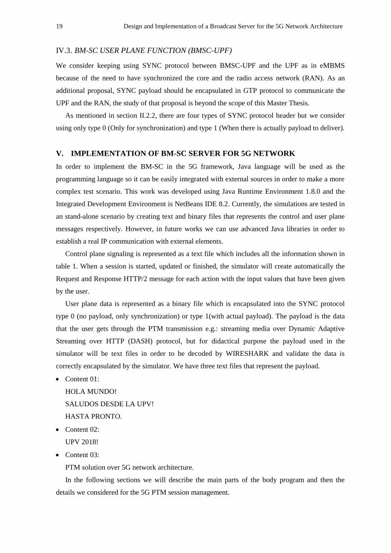
Update session: This option allows us to update the ARP and/or MBMS service area which
trigger the update session management of the session.
Fig.15. Session update procedure
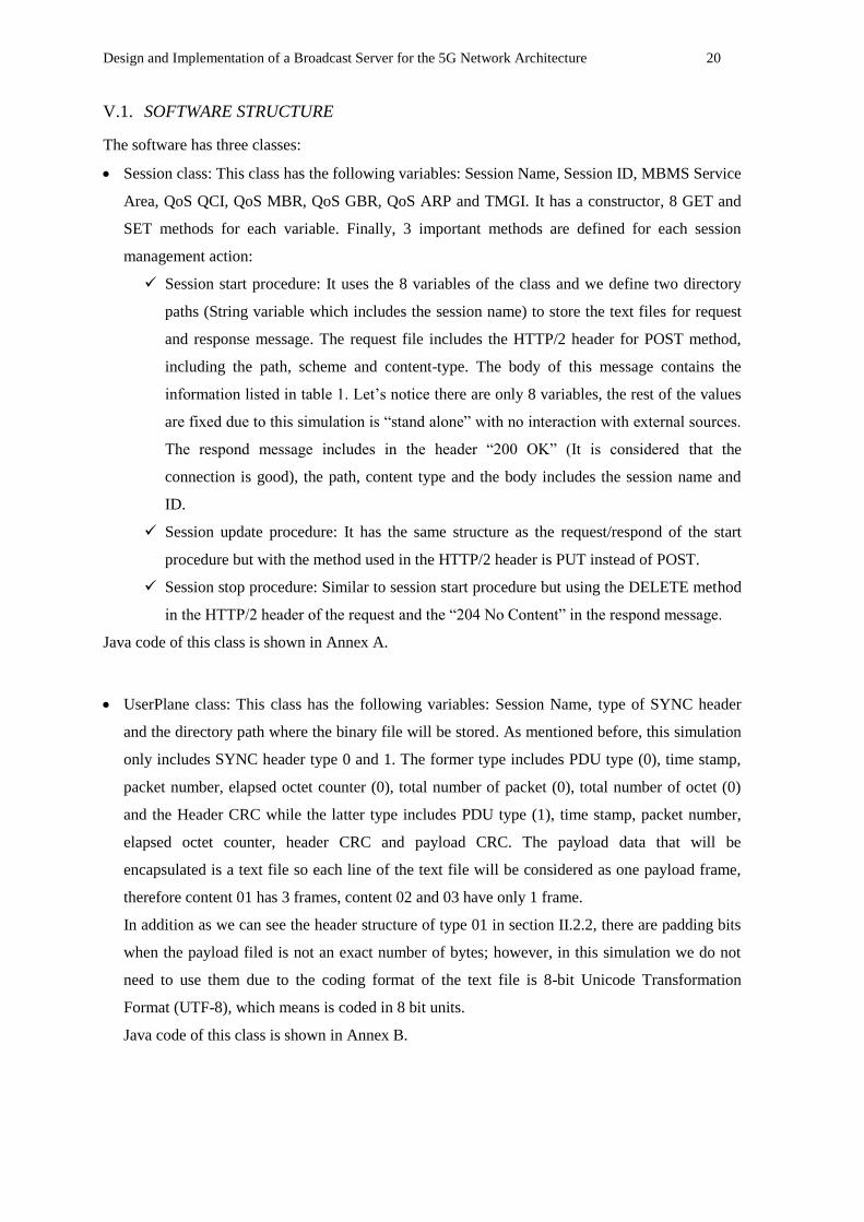
Stop session: With this option we can delete an existing session from the object array, we only
need to select the session to be removed.
Fig.16. Session stop procedure
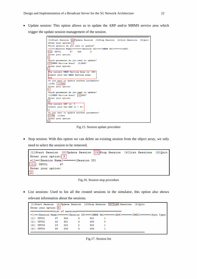
List sessions: Used to list all the created sessions in the simulator, this option also shows
relevant information about the sessions.
Fig.17. Session list
23 Design and Implementation of a Broadcast Server for the 5G Network Architecture
Quit: It is used to stop running the program.
Fig.18. Quit simulator procedure
VI. RESULTS
The results will be described as control plane and user plane results related to the session created,
updated and finished in the section V.
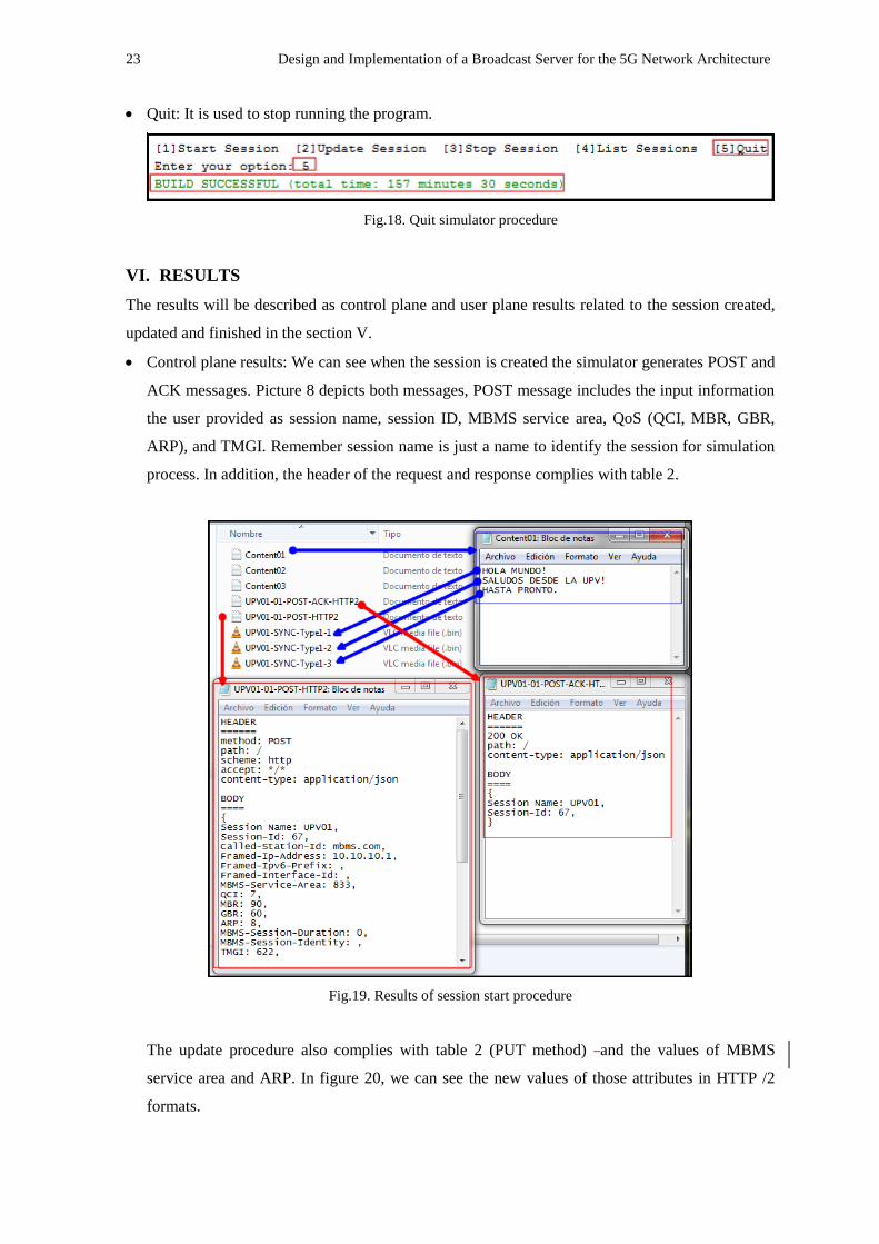
Control plane results: We can see when the session is created the simulator generates POST and
ACK messages. Picture 8 depicts both messages, POST message includes the input information
the user provided as session name, session ID, MBMS service area, QoS (QCI, MBR, GBR,
ARP), and TMGI. Remember session name is just a name to identify the session for simulation
process. In addition, the header of the request and response complies with table 2.
Fig.19. Results of session start procedure
The update procedure also complies with table 2 (PUT method) and the values of MBMS
service area and ARP. In figure 20, we can see the new values of those attributes in HTTP /2
formats.

Design and Implementation of a Broadcast Server for the 5G Network Architecture 24
Fig.20. Results of session update procedure
Finally, the stop procedure is similar to the update procedure. Figure 21 depicts the DELETE
and ACK messages. In this case the response indicates the “204 No Content” information in the
HTTP/2 header.
Fig.21. Results of session stop procedure
25 Design and Implementation of a Broadcast Server for the 5G Network Architecture
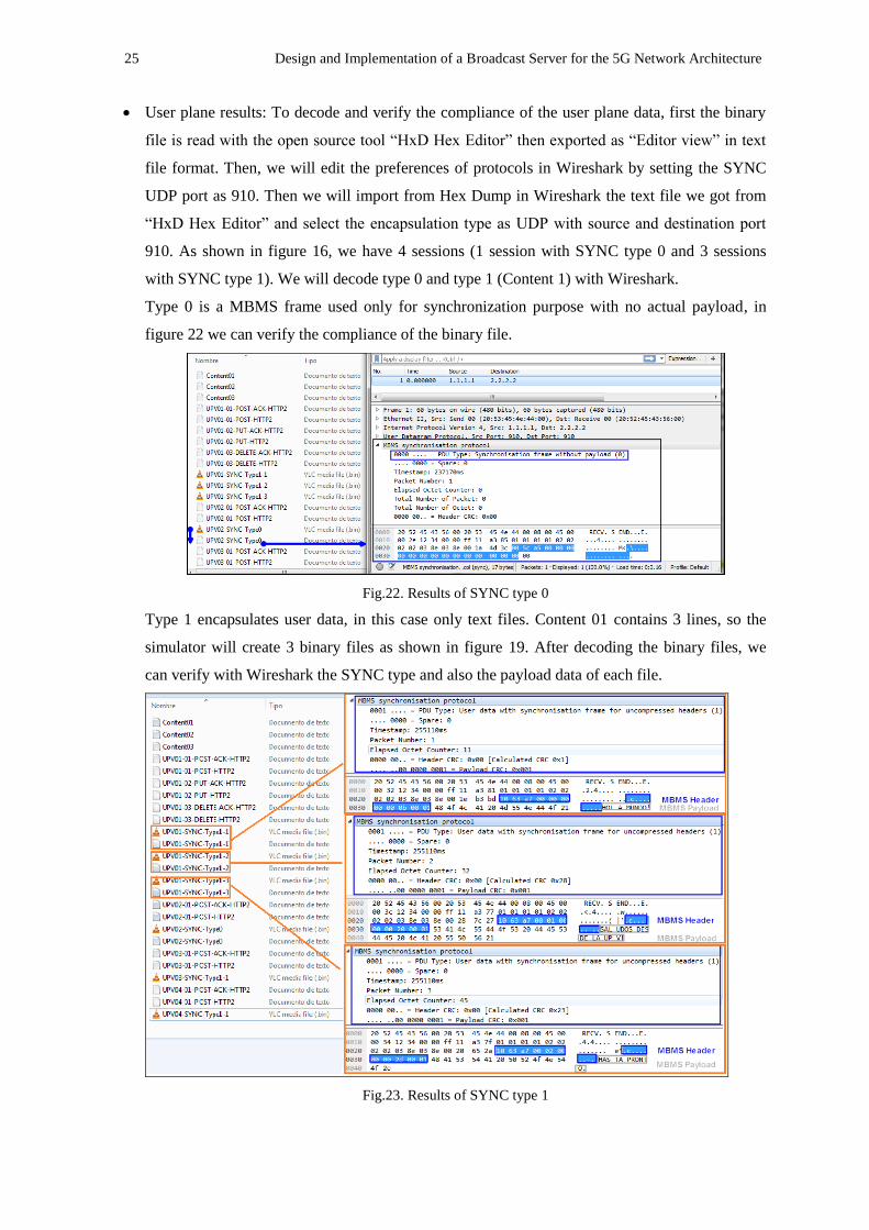
User plane results: To decode and verify the compliance of the user plane data, first the binary
file is read with the open source tool “HxD Hex Editor” then exported as “Editor view” in text
file format. Then, we will edit the preferences of protocols in Wireshark by setting the SYNC
UDP port as 910. Then we will import from Hex Dump in Wireshark the text file we got from
“HxD Hex Editor” and select the encapsulation type as UDP with source and destination port
910. As shown in figure 16, we have 4 sessions (1 session with SYNC type 0 and 3 sessions
with SYNC type 1). We will decode type 0 and type 1 (Content 1) with Wireshark.
Type 0 is a MBMS frame used only for synchronization purpose with no actual payload, in
figure 22 we can verify the compliance of the binary file.
Fig.22. Results of SYNC type 0
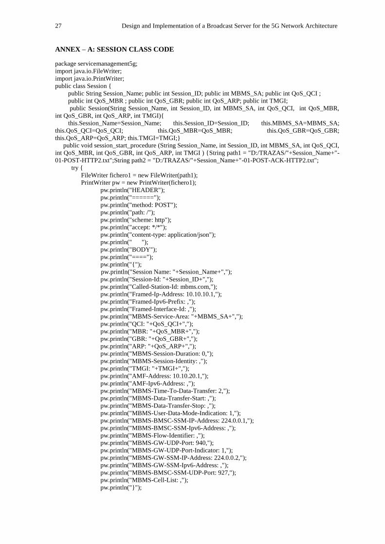
Type 1 encapsulates user data, in this case only text files. Content 01 contains 3 lines, so the
simulator will create 3 binary files as shown in figure 19. After decoding the binary files, we
can verify with Wireshark the SYNC type and also the payload data of each file.
Fig.23. Results of SYNC type 1
Design and Implementation of a Broadcast Server for the 5G Network Architecture 26
VII. CONCLUSIONS
The enhanced Multimedia Broadcast/Multicast Service (eMBMS) service provides a Point to
Multipoint (PTM) communications over 4G LTE network where the main element, within the
Core Network, that makes this possible is the Broadcast Multicast Service Center (BM-SC). The
latest version of eMBMS came with 3GPP Release 14. The latest revision of the 3GPP mobile
standard, Release 15, will not cover PTM services.
In this thesis, we implemented an eMBMS BM-SC following the new interfaces in the 5G-
Core- First; the BM-SC for 4G LTE is implemented, based on the 3GPP technical specifications
(DIAMETER protocol for control plane and SYNC protocol for user plane). Then, the
adaptation to 5G is performed i.e. the control plane is adapted for HTTP/2 instead of
DIAMETER while keeping the SYNC protocol for user plane.
In order to validate the software, both control and user plane, are output and stored as text and
binary files respectively. It has been found that the file traces comply with HTTP/2 and SYNC
protocol; so is proven that the 4G BM-SC can be extended to 5G. This 5G BM-SC could be
deployed in a 5G Network Architecture.
As future work, the 5G BM-SC can be integrated with external entities (Such as Content
Providers or Gateways) for researching purposes and testbed scenarios.
ACKNOWLEDGEMENTS
This Master Thesis based the design on the architecture proposal of the 5G-Xcast project [1],
deliverable 4.1 Mobile Core Network published on May 2018, Work Package 4 Network
Architecture and Management. Also, the lectures and presentations during the IEEE International
Symposium on Broadband Multimedia Systems and Broadcasting, during June 6th to 8th in
Valencia Spain, contributed to the development of this document.
REFERENCES
[1] 5G-Xcast Project - http://5g-xcast.eu
[2] Point-to-Multipoint Communication Enablers for the Fifth-Generation of Wireless Systems, IEEE
Communications Standard Magazine. D.Gomez, D.Návratil, S. Appleby, M.Stagg
[3] Evaluation and Optimization of Live Video and Audio Delivery over LTE Broadcast (eMBMS), Master
Thesis at Institute of Communication Systems and Data Processing, RWTH Aachen University. Luis
Carlos Paniagua Acuña, Jul. 2014.
[4] 3GPP, “TS 25.446, MBMS synchronization protocol (SYNC), Rel. 14,” Mar. 2017.
[5] 3GPP, “TS 23.501, System Architecture for the 5G System; Stage 2, Rel. 15,” Mar. 2018.
[6] 3GPP, “TS 29.500, Technical Realization of Service Based Architecture, Stage 3, Rel. 15,” Jun. 2018.
[7] IETF RFC 7540, Hypertext Transfer Protocol Version 2 (HTTP/2)
27 Design and Implementation of a Broadcast Server for the 5G Network Architecture
ANNEX – A: SESSION CLASS CODE
package servicemanagement5g;
import java.io.FileWriter;
import java.io.PrintWriter;
public class Session {
public String Session_Name; public int Session_ID; public int MBMS_SA; public int QoS_QCI ;
public int QoS_MBR ; public int QoS_GBR; public int QoS_ARP; public int TMGI;
public Session(String Session_Name, int Session_ID, int MBMS_SA, int QoS_QCI, int QoS_MBR,
int QoS_GBR, int QoS_ARP, int TMGI){
this.Session_Name=Session_Name; this.Session_ID=Session_ID; this.MBMS_SA=MBMS_SA;
this.QoS_QCI=QoS_QCI; this.QoS_MBR=QoS_MBR; this.QoS_GBR=QoS_GBR;
this.QoS_ARP=QoS_ARP; this.TMGI=TMGI;}
public void session_start_procedure (String Session_Name, int Session_ID, int MBMS_SA, int QoS_QCI,
int QoS_MBR, int QoS_GBR, int QoS_ARP, int TMGI ) {String path1 = "D:/TRAZAS/"+Session_Name+"-
01-POST-HTTP2.txt";String path2 = "D:/TRAZAS/"+Session_Name+"-01-POST-ACK-HTTP2.txt";
try {
FileWriter fichero1 = new FileWriter(path1);
PrintWriter pw = new PrintWriter(fichero1);
pw.println("HEADER");
pw.println("======");
pw.println("method: POST");
pw.println("path: /");
pw.println("scheme: http");
pw.println("accept: */*");
pw.println("content-type: application/json");
pw.println(" ");
pw.println("BODY");
pw.println("====");
pw.println("{");
pw.println("Session Name: "+Session_Name+",");
pw.println("Session-Id: "+Session_ID+",");
pw.println("Called-Station-Id: mbms.com,");
pw.println("Framed-Ip-Address: 10.10.10.1,");
pw.println("Framed-Ipv6-Prefix: ,");
pw.println("Framed-Interface-Id: ,");
pw.println("MBMS-Service-Area: "+MBMS_SA+",");
pw.println("QCI: "+QoS_QCI+",");
pw.println("MBR: "+QoS_MBR+",");
pw.println("GBR: "+QoS_GBR+",");
pw.println("ARP: "+QoS_ARP+",");
pw.println("MBMS-Session-Duration: 0,");
pw.println("MBMS-Session-Identity: ,");
pw.println("TMGI: "+TMGI+",");
pw.println("AMF-Address: 10.10.20.1,");
pw.println("AMF-Ipv6-Address: ,");
pw.println("MBMS-Time-To-Data-Transfer: 2,");
pw.println("MBMS-Data-Transfer-Start: ,");
pw.println("MBMS-Data-Transfer-Stop: ,");
pw.println("MBMS-User-Data-Mode-Indication: 1,");
pw.println("MBMS-BMSC-SSM-IP-Address: 224.0.0.1,");
pw.println("MBMS-BMSC-SSM-Ipv6-Address: ,");
pw.println("MBMS-Flow-Identifier: ,");
pw.println("MBMS-GW-UDP-Port: 940,");
pw.println("MBMS-GW-UDP-Port-Indicator: 1,");
pw.println("MBMS-GW-SSM-IP-Address: 224.0.0.2,");
pw.println("MBMS-GW-SSM-Ipv6-Address: ,");
pw.println("MBMS-BMSC-SSM-UDP-Port: 927,");
pw.println("MBMS-Cell-List: ,");
pw.println("}");
Design and Implementation of a Broadcast Server for the 5G Network Architecture 28
pw.close();} catch (Exception ex){
ex.printStackTrace();}
try {
FileWriter fichero2 = new FileWriter(path2);
PrintWriter pw = new PrintWriter(fichero2);
pw.println("HEADER");
pw.println("======");
pw.println("200 OK");
pw.println("path: /");
pw.println("content-type: application/json");
pw.println(" ");
pw.println("BODY");
pw.println("====");
pw.println("{");
pw.println("Session Name: "+Session_Name+",");
pw.println("Session-Id: "+Session_ID+",");
pw.println("}");
pw.close();} catch (Exception ex){
ex.printStackTrace();} }
public void session_update_procedure (String Session_Name, int Session_ID, int MBMS_SA, int
QoS_QCI, int QoS_MBR, int QoS_GBR, int QoS_ARP, int TMGI ) { String path1 =
"D:/TRAZAS/"+Session_Name+"-02-PUT-HTTP2.txt"; String path2 = "D:/TRAZAS/"+Session_Name+"-
02-PUT-ACK-HTTP2.txt";
try { FileWriter fichero1 = new FileWriter(path1);PrintWriter pw = new PrintWriter(fichero1);
pw.println("HEADER");
pw.println("======");
pw.println("method: PUT");
pw.println("path: /");
pw.println("scheme: http");
pw.println("accept: */*");
pw.println("content-type: application/json");
pw.println(" ");
pw.println("BODY");
pw.println("====");
pw.println("{");
pw.println("Session Name: "+Session_Name+",");
pw.println("Session-Id: "+Session_ID+",");
pw.println("Called-Station-Id: mbms.com,");
pw.println("Framed-Ip-Address: 10.10.10.1,");
pw.println("Framed-Ipv6-Prefix: ,");
pw.println("Framed-Interface-Id: ,");
pw.println("MBMS-Service-Area: "+MBMS_SA+",");
pw.println("QCI: "+QoS_QCI+",");
pw.println("MBR: "+QoS_MBR+",");
pw.println("GBR: "+QoS_GBR+",");
pw.println("ARP: "+QoS_ARP+",");
pw.println("MBMS-Session-Duration: 0,");
pw.println("MBMS-Session-Identity: ,");
pw.println("TMGI: "+TMGI+",");
pw.println("AMF-Address: 10.10.20.1,");
pw.println("AMF-Ipv6-Address: ,");
pw.println("MBMS-Time-To-Data-Transfer: 2,");
pw.println("MBMS-Data-Transfer-Start: ,");
pw.println("MBMS-Data-Transfer-Stop: ,");
pw.println("MBMS-User-Data-Mode-Indication: 1,");
pw.println("MBMS-BMSC-SSM-IP-Address: 224.0.0.1,");
pw.println("MBMS-BMSC-SSM-Ipv6-Address: ,");
pw.println("MBMS-Flow-Identifier: ,");
pw.println("MBMS-GW-UDP-Port: 940,");
pw.println("MBMS-GW-UDP-Port-Indicator: 1,");
29 Design and Implementation of a Broadcast Server for the 5G Network Architecture
pw.println("MBMS-GW-SSM-IP-Address: 224.0.0.2,");
pw.println("MBMS-GW-SSM-Ipv6-Address: ,");
pw.println("MBMS-BMSC-SSM-UDP-Port: 927,");
pw.println("MBMS-Cell-List: ,");
pw.println("}");
pw.close();} catch (Exception ex){
ex.printStackTrace();}
try {FileWriter fichero2 = new FileWriter(path2); PrintWriter pw = new PrintWriter(fichero2);
pw.println("HEADER");
pw.println("======");
pw.println("200 OK");
pw.println("path: /");
pw.println("content-type: application/json");
pw.println(" ");
pw.println("BODY");
pw.println("====");
pw.println("{");
pw.println("Session Name: "+Session_Name+",");
pw.println("Session-Id: "+Session_ID+",");
pw.println("}");
pw.close();} catch (Exception ex){
ex.printStackTrace();}}
public void session_stop_procedure (String Session_Name, int Session_ID, int MBMS_SA, int QoS_QCI,
int QoS_MBR, int QoS_GBR, int QoS_ARP, int TMGI ) {
String path1 = "D:/TRAZAS/"+Session_Name+"-03-DELETE-HTTP2.txt";
String path2 = "D:/TRAZAS/"+Session_Name+"-03-DELETE-ACK-HTTP2.txt";
try {FileWriter fichero1 = new FileWriter(path1);PrintWriter pw = new PrintWriter(fichero1);
pw.println("HEADER");
pw.println("======");
pw.println("method: DELETE");
pw.println("path: /");
pw.println("scheme: http");
pw.println("accept: */*");
pw.println("content-type: application/json");
pw.println(" ");
pw.println("BODY");
pw.println("====");
pw.println("{");
pw.println("Session Name: "+Session_Name+",");
pw.println("Session-Id: "+Session_ID+",");
pw.println("Called-Station-Id: mbms.com,");
pw.println("Framed-Ip-Address: 10.10.10.1,");
pw.println("Framed-Ipv6-Prefix: ,");
pw.println("Framed-Interface-Id: ,");
pw.println("MBMS-Service-Area: "+MBMS_SA+",");
pw.println("QCI: "+QoS_QCI+",");
pw.println("MBR: "+QoS_MBR+",");
pw.println("GBR: "+QoS_GBR+",");
pw.println("ARP: "+QoS_ARP+",");
pw.println("MBMS-Session-Duration: 0,");
pw.println("MBMS-Session-Identity: ,");
pw.println("TMGI: "+TMGI+",");
pw.println("AMF-Address: 10.10.20.1,");
pw.println("AMF-Ipv6-Address: ,");
pw.println("MBMS-Time-To-Data-Transfer: 2,");
pw.println("MBMS-Data-Transfer-Start: ,");
pw.println("MBMS-Data-Transfer-Stop: ,");
pw.println("MBMS-User-Data-Mode-Indication: 1,");
pw.println("MBMS-BMSC-SSM-IP-Address: 224.0.0.1,");
pw.println("MBMS-BMSC-SSM-Ipv6-Address: ,");
Design and Implementation of a Broadcast Server for the 5G Network Architecture 30
pw.println("MBMS-Flow-Identifier: ,");
pw.println("MBMS-GW-UDP-Port: 940,");
pw.println("MBMS-GW-UDP-Port-Indicator: 1,");
pw.println("MBMS-GW-SSM-IP-Address: 224.0.0.2,");
pw.println("MBMS-GW-SSM-Ipv6-Address: ,");
pw.println("MBMS-BMSC-SSM-UDP-Port: 927,");
pw.println("MBMS-Cell-List: ,");
pw.println("}");
pw.close();} catch (Exception ex){
ex.printStackTrace();}
try {FileWriter fichero2 = new FileWriter(path2); PrintWriter pw = new PrintWriter(fichero2);
pw.println("HEADER");
pw.println("======");
pw.println("204 No Content");
pw.println("path: /");
pw.println("content-type: application/json");
pw.println(" ");
pw.println("BODY");
pw.println("====");
pw.println("{");
pw.println("Session Name: "+Session_Name+",");
pw.println("Session-Id: "+Session_ID+",");
pw.println("}");
pw.close();} catch (Exception ex){
ex.printStackTrace();}}
public static void main (){}
public String getSessionName() {
return this.Session_Name;}
public void setSessionName(String SessionName) {this.Session_Name=SessionName;}
public int getSessionID() {return this.Session_ID;}
public void setSessionID(int SessionID) {this.Session_ID=SessionID;}
public int getMBMS_SA() {return this.MBMS_SA;}
public void setMBMSA_SA(int MBMSSA) {this.MBMS_SA=MBMSSA;}
public int getQCI() {return this.QoS_QCI;}
public void setQCI(int QCI) {this.QoS_QCI=QCI;}
public int getMBR() {return this.QoS_MBR;}
public void setMBR(int MBR) {this.QoS_MBR=MBR;}
public int getGBR() {return this.QoS_GBR;}
public void setGBR(int GBR) {this.QoS_GBR=GBR;}
public int getARP() {return this.QoS_ARP;}
public void setARP(int ARP) {this.QoS_ARP=ARP;}
public int getTMGI() { return this.TMGI;}
public void setTMGI(int TMGI_ID) {this.TMGI=TMGI_ID;}}
31 Design and Implementation of a Broadcast Server for the 5G Network Architecture
ANNEX – B: USER PLANE CLASS CODE
package servicemanagement5g;
import java.io.BufferedReader;
import java.io.File;
import java.io.FileNotFoundException;
import java.io.FileReader;
import java.io.IOException;
import java.io.RandomAccessFile;
import java.util.Date;
public class UserPlane {
String path;
int Type;
String SessionName;
public UserPlane(String path,int Type,String SessionName){ this.path=path; this.Type=Type;
this.SessionName=SessionName;}
public void UPSync(String path,int Type,String SessionName)throws FileNotFoundException,
IOException{String Linea; String L=""; long time = new Date().getTime();
byte a = (byte)(time >>> 8); byte b = (byte)(time);
if (Type==0){String pathUP = "D:/TRAZAS/"+SessionName+"-SYNC-Type0.bin";
byte[] type = {0}; byte[] header0 ={0,0,0,0,0,0,0,0,0,0,0,0,0}; byte [] packetnumber ={0,0};
RandomAccessFile demoFile =new RandomAccessFile( pathUP, "rw" ); demoFile.write(type);
demoFile.write(a); demoFile.write(b);demoFile.write(packetnumber); demoFile.write(header0);
}
else{try
{BufferedReader ficheroEntrada = new BufferedReader(
new FileReader(new File(path))); int NumLinea = 0; byte[] header1 ={0,1};
while ((Linea=ficheroEntrada.readLine()) != null) {L=L+Linea; int size = L.length();
byte[] type1 = {16}; byte packetNumber1 = (byte) (NumLinea>>> 8);
byte packetNumber2 = (byte) (NumLinea); byte octectNumber1 = (byte) (size>>> 24);
byte octectNumber2 = (byte) (size>>> 16); byte octectNumber3 = (byte) (size>>> 8);
byte octectNumber4 = (byte) (size); byte[] myBytes = Linea.getBytes();
String pathUP = "D:/TRAZAS/"+SessionName+"-SYNC-Type1-"+(NumLinea+1)+".bin";
RandomAccessFile demoFile2 =new RandomAccessFile( pathUP, "rw" );
demoFile2.write(type1); demoFile2.write(a); demoFile2.write(b);
demoFile2.write(packetNumber1);demoFile2.write(packetNumber2);
demoFile2.write(octectNumber1);demoFile2.write(octectNumber2);
demoFile2.write(octectNumber3);demoFile2.write(octectNumber4);
demoFile2.write(header1);demoFile2.write(myBytes);
NumLinea ++;}ficheroEntrada.close();}
catch (IOException errorDeFichero)
{System.out.println( errorDeFichero.getMessage() );}}}
public static void main() { }
public String getpath() {return this.path;}
public void setpath(String path) {this.path=path;}
public int getType() {return this.Type;}
public void setType(int Type) {this.Type=Type;}
public String getSessionName() {return this.SessionName;}
public void setSessionName(String SessionName) {this.SessionName=SessionName;}}
Design and Implementation of a Broadcast Server for the 5G Network Architecture 32
ANNEX – C: SESSION MANAGEMENT 5G CLASS CODE
package servicemanagement5g;
import java.io.IOException;
import java.util.ArrayList;
import java.util.Scanner;
public class ServiceManagement5G {
public String SessionName;public int SessionID;public int MBMSSA;public int QoSQCI;
public int QoSMBR;public int QoSGBR;public int QoSARP;public int TMGI;public String path;
public int Type;public ArrayList <Session> MBMSSessions;
public ArrayList <UserPlane> MBMSUP;public ServiceManagement5G(){
this.MBMSSessions = new ArrayList<>(1);this.MBMSUP = new ArrayList <>(1);}
public void AddSesion() throws IOException{
Session MBMSAux = new Session(SessionName, SessionID, MBMSSA, QoSQCI, QoSMBR,
QoSGBR, QoSARP, TMGI);
UserPlane MBMSAuxUP = new UserPlane(path,Type,SessionName);
String pathSession="";
Scanner scanner = new Scanner(System.in);
System.out.println ("Enter name of the session: ");
String namesession = scanner.nextLine();
if(this.MBMSSessions.size()>0){
for (int i=0;i<this.MBMSSessions.size();i++){
if(namesession.equals(this.MBMSSessions.get(i).Session_Name)){
System.out.println ("Repeated Session Name. Please enter another n ame for the session: ");
namesession = scanner.nextLine();
MBMSAux.setSessionName(namesession);MBMSAuxUP.setSessionName(namesession);}
else{MBMSAux.setSessionName(namesession);}}}
else{MBMSAux.setSessionName(namesession);
MBMSAuxUP.setSessionName(namesession);}
System.out.println ("Enter ID of the session: ");int IDsession = scanner.nextInt();
if(this.MBMSSessions.size()>0){for (int i=0;i<this.MBMSSessions.size();i++){
if(IDsession==this.MBMSSessions.get(i).Session_ID){
System.out.println ("Repeated ID. Please enter another ID for the session: ");
IDsession = scanner.nextInt();MBMSAux.setSessionID(IDsession);}
else{MBMSAux.setSessionID(IDsession);}}}else{MBMSAux.setSessionID(IDsession);}
System.out.println ("Enter MBMS Service Area [0-65535]: ");
int MBMSSAsession = scanner.nextInt();MBMSAux.setMBMSA_SA(MBMSSAsession);
System.out.println ("Enter QCI [1-9]: ");int QCIsession = scanner.nextInt();
MBMSAux.setQCI(QCIsession);System.out.println ("Enter MBR [Kbps]: ");
int MBRsession = scanner.nextInt();MBMSAux.setMBR(MBRsession);
System.out.println ("Enter GBR [Kbps]: ");int GBRsession = scanner.nextInt();
MBMSAux.setGBR(GBRsession);System.out.println ("Enter ARP [1-9]: ");
int ARPsession = scanner.nextInt();MBMSAux.setARP(ARPsession);
System.out.println ("Enter TMGI [000000 - 16 777 215]: ");int TMGIsession = scanner.nextInt();
MBMSAux.setTMGI(TMGIsession);
System.out.println ("Enter the type of SYNC protocol for User Plane data [0] [1]: ");
int typeSync = scanner.nextInt();MBMSAuxUP.setType(typeSync);
if(typeSync==1){
System.out.println ("Enter the media you want to broadcast: [1]Content-01 [2]Content-02
[3]Content-03");//Nueva línea para UP
int content = scanner.nextInt();
switch (content){
case 1:
MBMSAuxUP.setpath("D:/TRAZAS/Content01.txt");
pathSession ="D:/TRAZAS/Content01.txt";MBMSAuxUP.setpath(pathSession);
break;case 2:
MBMSAuxUP.setpath("D:/TRAZAS/Content02.txt");
pathSession ="D:/TRAZAS/Content02.txt" ;MBMSAuxUP.setpath(pathSession);
break;case 3:
MBMSAuxUP.setpath("D:/TRAZAS/Content03.txt");
33 Design and Implementation of a Broadcast Server for the 5G Network Architecture
pathSession ="D:/TRAZAS/Content03.txt" ;MBMSAuxUP.setpath(pathSession);
break;}}else{}
MBMSAux.session_start_procedure(namesession,IDsession,MBMSSAsession,QCIsession,MBRsessi
on,GBRsession,ARPsession,TMGIsession);
MBMSAuxUP.UPSync(pathSession, typeSync, namesession);
this.MBMSSessions.add(MBMSAux);this.MBMSUP.add(MBMSAuxUP);}
public void UpdateSession(){
Session MBMSAux = new Session(SessionName, SessionID, MBMSSA, QoSQCI, QoSMBR,
QoSGBR, QoSARP, TMGI);
Scanner scannerupd = new Scanner(System.in);
System.out.println ("Which session do you want to update?");
System.out.println ("=[]==[Session Name]=======[Session ID]====[MBMS
SA]=======[ARP]");
for (int m=0;m<MBMSSessions.size();m++){
System.out.println ("["+(m+1)+"]: "+this.MBMSSessions.get(m).Session_Name+"
"+this.MBMSSessions.get(m).Session_ID+" "+this.MBMSSessions.get(m).MBMS_SA+"
"+this.MBMSSessions.get(m).QoS_ARP); }
System.out.println("Enter your option: ");
int p = scannerupd.nextInt()-1;
while(p>=this.MBMSSessions.size()){
System.out.println ("INVALID OPTION!");
System.out.println("Enter your option: ");
p=scannerupd.nextInt()-1;}
int respuesta = 1;
while (respuesta >0){
System.out.println ("Which parameter do you want to update?");
System.out.println ("[1]MBMS Service Area? [2]ARP?");
System.out.println("Enter your option: ");
int option = scannerupd.nextInt();
while(option >2){System.out.println ("INVALID OPTION!");
System.out.println ("Which parameter do you want to update?");
System.out.println ("[1]MBMS Service Area? [2]ARP?");
System.out.println("Enter your option: ");option = scannerupd.nextInt(); }
switch (option){
case 1:
System.out.println ("The current MBMS Service Area is:
"+this.MBMSSessions.get(p).MBMS_SA);
System.out.println ("Insert your new MBMS Service Area: ");
this.MBMSSessions.get(p).MBMS_SA=scannerupd.nextInt();break;
case 2:
System.out.println ("The current ARP is: "+this.MBMSSessions.get(p).QoS_ARP);
System.out.println ("Insert your new ARP [1 - 9]: ");
this.MBMSSessions.get(p).QoS_ARP=scannerupd.nextInt();break;}
System.out.println ("Do you want to update another parameter?");
System.out.println ("[0]No [1]Yes");System.out.println("Enter your option: ");
respuesta = scannerupd.nextInt();}
MBMSAux.session_update_procedure(this.MBMSSessions.get(p).Session_Name,
this.MBMSSessions.get(p).Session_ID,this.MBMSSessions.get(p).MBMS_SA,this.MBMSSessions.g
et(p).QoS_QCI,this.MBMSSessions.get(p).QoS_MBR,this.MBMSSessions.get(p).QoS_GBR,this.MB
MSSessions.get(p).QoS_ARP,this.MBMSSessions.get(p).TMGI);}
public void StopSession(){
Session MBMSAux = new Session(SessionName, SessionID, MBMSSA, QoSQCI, QoSMBR,
QoSGBR, QoSARP, TMGI);
Scanner scannerstp = new Scanner(System.in);
System.out.println ("=[]==[Session Name]=======[Session ID]");
for (int m=0;m<MBMSSessions.size();m++){
System.out.println ("["+(m+1)+"]: "+this.MBMSSessions.get(m).Session_Name+"
"+this.MBMSSessions.get(m).Session_ID);}System.out.println("Enter your option: ");
int p = scannerstp.nextInt()-1;
Design and Implementation of a Broadcast Server for the 5G Network Architecture 34
MBMSAux.session_stop_procedure(this.MBMSSessions.get(p).Session_Name,this.MBMSSessions.get(p).S
ession_ID,this.MBMSSessions.get(p).MBMS_SA,this.MBMSSessions.get(p).QoS_QCI,this.MBMSSessions
.get(p).QoS_MBR,this.MBMSSessions.get(p).QoS_GBR,this.MBMSSessions.get(p).QoS_ARP,this.MBMS
Sessions.get(p).TMGI);
this.MBMSSessions.remove(p);this.MBMSUP.remove(p); }public void CheckSession(){
System.out.println ("================List of
sessions===============================");
System.out.println ("=[]==[Session Name]=======[Session ID]====[MBMS
SA]=======[ARP]=======[TMGI]=======[Sync Type]");
for (int m=0;m<MBMSSessions.size();m++){
System.out.println ("["+(m+1)+"]: "+this.MBMSSessions.get(m).Session_Name+"
"+this.MBMSSessions.get(m).Session_ID+" "+this.MBMSSessions.get(m).MBMS_SA+"
"+this.MBMSSessions.get(m).QoS_ARP+" "+this.MBMSSessions.get(m).TMGI+"
"+this.MBMSUP.get(m).Type);
}}
public static void main(String[] args) throws IOException{
Scanner scannermain = new Scanner(System.in);
System.out.println ("MBMS Simulator!!!");
System.out.println
("=======================================================================
========");
System.out.println ("[1]Start Session [2]Update Session [3]Stop Session [4]List Sessions
[5]Quit");
System.out.print("Enter your option: ");int option = scannermain.nextInt();
ServiceManagement5G SM = new ServiceManagement5G();while (option != 5){
switch (option){
case 1:SM.AddSesion();System.out.println
("=======================================================================
========"); System.out.println ("[1]Start Session [2]Update Session [3]Stop Session [4]List
Sessions [5]Quit");
System.out.print("Enter your option: ");option = scannermain.nextInt(); break;
case 2:SM.UpdateSession();System.out.println
("=======================================================================
========");
System.out.println ("[1]Start Session [2]Update Session [3]Stop Session [4]List Sessions
[5]Quit");
System.out.print("Enter your option: ");option = scannermain.nextInt(); break;
case 3:SM.StopSession();System.out.println
("=======================================================================
========");
System.out.println ("[1]Start Session [2]Update Session [3]Stop Session [4]List Sessions
[5]Quit");
System.out.print("Enter your option: ");option = scannermain.nextInt(); break;
case 4:
SM.CheckSession();System.out.println
("=======================================================================
========");
System.out.println ("[1]Start Session [2]Update Session [3]Stop Session [4]List Sessions
[5]Quit");System.out.print("Enter your option: ");option = scannermain.nextInt(); break;
default: System.out.println ("INVALID OPTION!");System.out.println
("=======================================================================
========");
System.out.println ("[1]Start Session [2]Update Session [3]Stop Session [4]List Sessions
[5]Quit");System.out.print("Enter your option: ");option = scannermain.nextInt();
break;}}}}
35 Design and Implementation of a Broadcast Server for the 5G Network Architecture
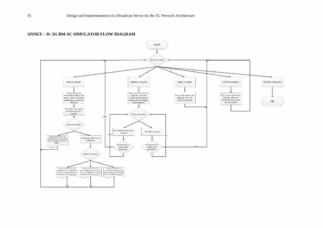
ANNEX – D: 5G BM-SC SIMULATOR FLOW DIAGRAM
Recommended