APPROVED FOR PUBLIC RELEASE – DISTRIBUTION IS UNLIMITED
NASA TECHNICAL STANDARD
NASA-STD-5017A
National Aeronautics and Space Administration Approved: 2015-07-31
Washington, DC 20546-0001 Superseding NASA-STD-5017
DESIGN AND DEVELOPMENT
REQUIREMENTS FOR MECHANISMS
MEASUREMENT SYSTEM IDENTIFICATION:
METRIC/SI (ENGLISH)
NASA-STD-5017A
APPROVED FOR PUBLIC RELEASE – DISTRIBUTION IS UNLIMITED
2 of 77
DOCUMENT HISTORY LOG
Status Document
Revision
Approval Date Description
Baseline 2006-06-13 Initial Release
Revision A 2015-07-31 General revision.
Language for nearly every requirement was
altered for clarity.
Some requirements were deleted or combined
with other requirements, and new requirements
have been added based on lessons learned with
the document and engineering state of the art.
Rationale was added for all requirements.
Appendix A, Best Practices for Mechanisms,
was added for guidance.

NASA-STD-5017A
APPROVED FOR PUBLIC RELEASE – DISTRIBUTION IS UNLIMITED
3 of 77
FOREWORD
This Standard is published by the National Aeronautics and Space Administration (NASA) to
provide uniform engineering and technical requirements for processes, procedures, practices, and
methods that have been endorsed as standard for NASA programs and projects, including
requirements for selection, application, and design criteria of an item.
This Standard is approved for use by NASA Headquarters and NASA Centers, including
Component Facilities and Technical and Service Support Centers.
This Standard establishes uniform design, development, and verification requirements for
mechanisms and mechanism components whose correct operation is required for safety or
mission success.
Requests for information, corrections, or additions to this Specification should be submitted via
“Feedback “in the NASA Technical Standards System at https://standards.nasa.gov/.
Original Signed By: 2015-07-31
Ralph R. Roe, Jr. Approval Date
NASA Chief Engineer

NASA-STD-5017A
APPROVED FOR PUBLIC RELEASE – DISTRIBUTION IS UNLIMITED
4 of 77
SECTION
TABLE OF CONTENTS
PAGE
DOCUMENT HISTORY LOG ............................................................................................ 2
FOREWORD ...................................................................................................................... 3
TABLE OF CONTENTS .................................................................................................... 4
LIST OF APPENDICES ..................................................................................................... 5
LIST OF FIGURES ............................................................................................................. 6
LIST OF TABLES .............................................................................................................. 6
1. SCOPE ................................................................................................................. 7
1.1 Purpose ................................................................................................................. 7
1.2 Applicability ......................................................................................................... 7
1.3 Tailoring ............................................................................................................... 7
2. APPLICABLE DOCUMENTS ......................................................................... 7
2.1 General ................................................................................................................. 7
2.2 Government Documents ....................................................................................... 7
2.3 Non-Government Documents .............................................................................. 8
2.4 Order of Precedence ............................................................................................. 8
3. ACRONYMS AND DEFINITIONS ................................................................. 8
3.1 Acronyms and Abbreviations ............................................................................... 8
3.2 Definitions ............................................................................................................ 9
3.2.1 Definitions of Variables ....................................................................................... 9
3.2.2 Definitions of Terms ............................................................................................ 9
4. REQUIREMENTS ............................................................................................. 12
4.1 Tolerancing ........................................................................................................... 12
4.2 Clearances ............................................................................................................ 13
4.3 Torque and Force Margins ................................................................................... 14
4.3.1 Servomechanism Margins .................................................................................... 18
4.4 Stroke Margin ....................................................................................................... 18
4.5 Electrical Bonding and Grounding ....................................................................... 19
4.6 Lubrication ........................................................................................................... 19
4.7 Structural Requirements ....................................................................................... 21
4.8 Bearings ................................................................................................................ 22
4.9 Motors .................................................................................................................. 27
4.9.1 Electrically Commutated Brushless Motors ......................................................... 27
4.9.2 Stepper Motors ..................................................................................................... 28
4.9.3 Brush Motors ........................................................................................................ 29
4.10 Springs .................................................................................................................. 29
4.11 Gears ..................................................................................................................... 29
4.12 Dampers ............................................................................................................... 30

NASA-STD-5017A
APPROVED FOR PUBLIC RELEASE – DISTRIBUTION IS UNLIMITED
5 of 77
TABLE OF CONTENTS (Continued)
4.13 Separable Interfaces ............................................................................................. 31
4.14 Pulleys .................................................................................................................. 31
4.15 Switches ............................................................................................................... 32
4.16 Fasteners ............................................................................................................... 32
4.17 Quick Release Pins ............................................................................................... 33
4.18 Released Degrees of Freedom .............................................................................. 33
4.19 Threaded Interfaces .............................................................................................. 33
4.20 Heritage Mechanisms ........................................................................................... 34
4.21 Performance Testing ............................................................................................ 34
4.22 Qualification Testing ............................................................................................ 34
4.22.1 Design Life Testing .............................................................................................. 36
4.23 Acceptance Testing .............................................................................................. 38
4.24 Mechanism Installation ........................................................................................ 40
APPENDICES
A Best Practices for Mechanisms............................................................................. 41
A.1 Purpose ................................................................................................................. 41
A.2 Best Practices ....................................................................................................... 41
A.2.1 Torque and Force Margins ................................................................................... 41
A.2.2 Lubrication ........................................................................................................... 42
A.2.3 Bearings ................................................................................................................ 47
A.2.3.1 Ball Bearings ........................................................................................................ 47
A.2.3.2 Roller and Needle Bearings .................................................................................. 52
A.2.3.3 Spherical Plain Bearings ...................................................................................... 52
A.2.3.4 Plain Bearings ...................................................................................................... 53
A.2.3.5 Linear Bearings .................................................................................................... 53
A.2.4 Motors .................................................................................................................. 53
A.2.4.1 DC Motor Types and Selection ............................................................................ 53
A.2.4.2 Stepper Motor Performance Analysis .................................................................. 60
A.2.4.3 Torque Profile Test for Electronically Commutated Motors and Drive
Electronics ............................................................................................................
61
A.2.5 Springs .................................................................................................................. 62
A.2.6 Gears ..................................................................................................................... 63
A.2.6.1 Harmonic Drives .................................................................................................. 63
A.2.7 Fastening .............................................................................................................. 64
A.2.8 Quick Release Pins ............................................................................................... 64
A.2.8.1 Quick Release Pin History ................................................................................... 64
A.2.8.2 Quick Release Pin Failures in the Space Program ............................................... 65
A.2.8.3 Current Quick Release Pin Best Practices ............................................................ 66
A.2.9 Inspection ............................................................................................................. 67
A.2.10 Qualification Testing ............................................................................................ 68

NASA-STD-5017A
APPROVED FOR PUBLIC RELEASE – DISTRIBUTION IS UNLIMITED
6 of 77
TABLE OF CONTENTS (Continued)
A.2.10.1 Design Life Testing .............................................................................................. 71
A.2.11 Acceptance Testing .............................................................................................. 73
A.2.12 Protoflight Testing ................................................................................................ 75
B References ............................................................................................................ 76
B.1 Purpose ................................................................................................................. 76
B.2 References ............................................................................................................ 76
B.2.1 Government Documents ....................................................................................... 76
B.2.2 Non-Government Documents .............................................................................. 77
FIGURE
LIST OF FIGURES
PAGE
1 Illustration of Length and Width for Various Examples of Mechanisms Using
a Set of Guides .....................................................................................................
26
2 Illustration of Moment Arm, Effective Length, and Width for a Single Linear
Bearing Application .............................................................................................
27
3 Pulley Guard Illustration ...................................................................................... 32
4 Illustration of the Effect of Saturation on Actuator Output ................................. 41
5 Diagram of a Typical Quick Release Pin ........................................................... 64
TABLE
LIST OF TABLES
PAGE
1 Minimum Torque/Force Margin Factors .............................................................. 15
2 Allowable Contact Stress for Bearing Materials Under Non-Operational Limit
Loads ....................................................................................................................
23
3 Factors of Safety for Springs ................................................................................ 62
4 Recommended Environmental Qualification Test Matrix for
Mechanisms ..........................................................................................................
70
5 Recommended Testing Sequence ......................................................................... 70
6 Recommended Environmental Acceptance Test Matrix for
Mechanisms ..........................................................................................................
74

NASA-STD-5017A
APPROVED FOR PUBLIC RELEASE – DISTRIBUTION IS UNLIMITED
7 of 77
DESIGN AND DEVELOPMENT
REQUIREMENTS FOR MECHANISMS
1. SCOPE
1.1 Purpose
The purpose of this Standard is to establish common National Aeronautics and Space
Administration (NASA) design, development, and test requirements for mechanisms whose
operation is required for safety or mission success.
1.2 Applicability
This Standard is applicable to space flight mechanisms, including valves and ordnance-operated
mechanical devices that are designed, built, or acquired by or for NASA, though it may also
serve as a useful guidance document for other systems such as ground support equipment (GSE).
This Standard does not address human factors requirements. Adherence to this Standard does not
in and of itself exempt a mechanism from any fault tolerance or hazard control requirements. The
requirements and best practices in this Standard may serve as a useful basis for evaluating
rationale for variances to fault tolerance requirements that may be proposed for mechanisms.
This Standard is approved for use by NASA Headquarters and NASA Centers, including
Component Facilities and Technical and Service Support Centers, and may be cited in contract,
program, and other Agency documents as a technical requirement. This Standard may also apply to
the Jet Propulsion Laboratory or to other contractors, grant recipients, or parties to agreements only
to the extent specified or referenced in their contracts, grants, or agreements.
Requirements are numbered and indicated by the word “shall.” Explanatory or guidance text is
indicated in italics beginning in section 4.
1.3 Tailoring
Tailoring of this Standard for application to a specific program or project shall be formally
documented as part of program or project requirements and approved by the Technical Authority.
2. APPLICABLE DOCUMENTS
2.1 General
2.2 Government Documents
None.

NASA-STD-5017A
APPROVED FOR PUBLIC RELEASE – DISTRIBUTION IS UNLIMITED
8 of 77
2.3 Non-Government Documents
None.
2.4 Order of Precedence
This Standard establishes requirements for mechanisms whose operation is required for safety or
mission success but does not supersede nor waive established Agency requirements found in
other documentation.
2.4.1 Conflicts between this Standard and other requirements documents shall be resolved by
the responsible Technical Authority.
3. ACRONYMS AND DEFINITIONS
3.1 Acronyms and Abbreviations
°C degrees centigrade
AA arithmetic average
ABEC Annular Bearing Engineering Council
ABMA American Bearing Manufacturing Association
AGMA American Gear Manufacturers Association
BLDC brushless direct current
CEVM consumable electrode vacuum melted
CMG control moment gyroscope
DC direct current
DFL dry film lubricant
EC electronically commutated
EHD elastohydrodynamic
EMC electromagnetic compatibility
EMI electromagnetic interference
EVA extravehicular activity
FS factor of safety
GSE ground support equipment
HRC Rockwell C hardness
HST Hubble Space Telescope
Hz Hertz
ISS International Space Station
ksi thousand pounds per square inch
MAC multiply alkylated cyclopentane
MPa megapascals
NASA National Aeronautics and Space Administration
NLGI National Lubricating Grease Institute
PCVD physical chemical vapor deposited
PIP push in and pull
PFPE perfluoropolyalkylether

NASA-STD-5017A
APPROVED FOR PUBLIC RELEASE – DISTRIBUTION IS UNLIMITED
9 of 77
PTFE polytetrafluoroethylene
VAR vacuum arc remelted
VIM vacuum induction melted
3.2 Definitions
3.2.1 Definitions of Variables
σ standard deviation
motor torque
ferror frequency of harmonic drive output gear error
current drawn by a motor
Kcrit life test criticality factor
Kcycle the factor applied to number of cycles within a defined cycle range
when calculating mechanism life test cycles
Kf factor applied to each individual fixed resistive torque in a torque
margin calculation
Klub lubrication factor
Km motor constant
Kt torque constant
Kv factor applied to each individual variable resistive torque in a torque
margin calculation
N harmonic of interest
Ncycle the number of cycles within a defined cycle range when calculating
mechanism life test cycles
P resistive power loss
Rt resistance across motor terminals
Tavail the minimum available torque or force generated by a mechanism at
worst case environmental conditions at any time in its life
Tf individual fixed resistive torques that are well-known and not strongly
influenced by friction, temperature, life, or other highly variable
phenomena.
Tv individual resistive torques that may vary over environmental
conditions and life
3.2.2 Definitions of Terms
Bearing Preload: The equal and opposite axial load on each of two bearings or bearing
sets mounted on a common axis.
Cold Welding: A phenomenon in which similar adjacent metal surfaces molecularly
bond to one another given sufficient cleanliness, time, and contact pressure.
Contact Ellipse: The area of contact between the ball and raceway that occurs as a
result of elastic deformation of both parts under load.

NASA-STD-5017A
APPROVED FOR PUBLIC RELEASE – DISTRIBUTION IS UNLIMITED
10 of 77
Coulomb Friction Torque: The parasitic torque in a bearing due only to the sliding
friction generated by the relative motion between the balls and the raceways. Note:
Generally, this torque has to be assessed at low speeds because the effect of drag on the
bearing from the liquid lubricant starts to affect the torque at higher speeds.
Deployable: A component that is moved from a stowed position on the spacecraft to
an extended position while remaining connected to the spacecraft.
Design Factor of Safety: A multiplying factor to be applied to limit loads or stresses
for the purposes of analytical assessment.
Detent Torque: The amount of magnetic torque that a motor produces to resist motion
when it is not energized.
Dynamic Clearance: The minimum distance between two entities when the entities are
in motion and subjected to service environments.
Dynamic Torque: The torque necessary to achieve a required acceleration of a
mechanism.
Hard Preload: A bearing preload approach in which the bearings are clamped together
without spring or diaphragm elements.
Holding Torque: The torque necessary to prevent motion of a mechanism under
external load.
Kickoff Spring: A spring intended to overcome forces present during initial separation
of a contacting interface.
L0.05 Life: The life at which 0.05 percent of the bearings in an application can be
expected to have failed due to rolling contact fatigue or, alternatively, the life at which 99.95
percent of the bearings will still be operating. Note: The L0.05 life of the bearing is theoretical
and may not represent actual service life of the bearing.
Lubricant: A material with low shear resistance that reduces friction and wear. Note:
Lubricants can include gases, reaction films, liquids, and solids.
Quick-Release Pin: A pin with a fast-acting retention and release mechanism built into
the pin. Note; Also known as a PIP (push in and pull) pin. Quick release pins come in a
variety of forms but generally utilize a spring-loaded central shaft to actuate one or more
retention balls that are retained in the housing via swages.
Mechanical Stop: A feature intended to prevent a mechanism component from
extending beyond a prescribed travel limit by physically impeding motion of the component,
also known as a hard stop.
NASA-STD-5017A
APPROVED FOR PUBLIC RELEASE – DISTRIBUTION IS UNLIMITED
11 of 77
Mechanism: An assembly in which one mechanical part moves relative to another
mechanical part.
Microstepping: A method of achieving smoother motion, smaller step angles, or more
precise positioning of a stepper motor by using a controller to rotate the stator magnetic field
through an arbitrary stepping angle that is less than the cardinal step size.
Motor Constant: A figure of merit used to evaluate a motor’s ability to transform
electrical power to mechanical power and compare the relative efficiencies and output
power capabilities of different motors, defined as
𝑲𝒎 =𝝉
√𝑷 𝐨𝐫 𝑲𝒎 =
𝑲𝒕
√𝑹𝒕
where Km is the motor constant, is the motor torque, P is the resistive power loss, Kt is the
torque constant, and Rt is the resistance across the motor terminals.
Pull-in Torque: The maximum constant torque for a given speed, inertial load, and
controller under which a stepper motor will accelerate from rest to operating speed, stop, or
reverse direction in synchronism with input pulses (i.e., without loss of steps). Note: Pull-in
torque is determined using 100 percent pulse duty cycle unless defined otherwise.
Pull-out Torque: The torque at which a stepper motor begins to lose synchronization
as its torque load is increased while operating at its desired speed. Note: Typically, a curve
plotting torque versus step rate (or rotor speed) is produced. This curve represents the
maximum torque that the stepper motor can supply to a load at any given speed. Any torque
or speed required that exceeds this curve will cause the motor to lose synchronization. Pull-
out torque is affected by drive voltage and phase switching techniques.
Separation Nut: A segmented nut in which the segments are held together for retention
of a bolt and then allowed to release through a mechanical action that is triggered on
command. The release may be triggered via pyrotechnics or, when low source shock is
necessary, non-explosive means such as shape memory alloys.
Servomechanism: An automatic device that uses error-sensing negative feedback to
correct the performance of a mechanism.
Spring Preload: See “Soft Preload.”
Starting Torque: The torque necessary to initiate motion in a mechanism.
Static Clearance: The minimum distance between two entities when the entities
are at rest.
Step Stability Analysis: An analytical method of quantifying stepper motor system
performance by evaluating dynamic response to step commands.

NASA-STD-5017A
APPROVED FOR PUBLIC RELEASE – DISTRIBUTION IS UNLIMITED
12 of 77
Structural Fastener: A fastener that is used for structural purposes only, is installed on
the ground only, and whose configuration is not altered during flight.
Torque Constant: The ratio of the motor torque to the current drawn by the motor,
defined as
𝑲𝒕 =𝝉
𝑰
where Kt is the torque constant, is the motor torque, and I is the current drawn by the motor.
Torque Ripple: A periodic variation in torque as an element rotates.
Tribological Coating: A coating applied to a surface for the purpose of reducing
friction or increasing wear resistance.
Yield Load: The product of the design limit load and the yield factor of safety.
4. REQUIREMENTS
4.1 Tolerancing
a. Dimensional tolerances on all moving parts and intentional interference-fit parts shall
be established and documented via a dimensional analysis to ensure that proper functional
performance is maintained under all natural and induced environmental conditions and
configurations.
Tolerancing and dimensional analysis is important not only for ensuring external clearances, but
also for ensuring proper mechanism function in the first place. Tolerancing is too often
considered as an afterthought of the design during the drawing creation phase and established
without a thorough understanding of the tolerance drivers. Establishing the tolerances via a
documented dimensional analysis helps drive the understanding of the effects of tolerances and
other factors, and allows for easy review and revision later.
b. The dimensional analysis shall account for the following:
(1) Manufacturing, assembly, and alignment tolerances.
(2) Temperature.
(3) Temperature gradients.
(4) Vibration.
(5) Deflections due to external loads.
(6) Deflections due to operational loads.
(7) Adjustability and rigging of the mechanism parts.

NASA-STD-5017A
APPROVED FOR PUBLIC RELEASE – DISTRIBUTION IS UNLIMITED
13 of 77
The factors to be considered in the dimensional analysis are similar to those considered for
clearances. Additional factors may be appropriate for consideration based on individual
applications. Verification that these factors have been considered is expected to include line
items in the analysis documentation for each factor in the dimensional analysis, or if a particular
factor does not apply in a given situation, rationale for its inapplicability.
4.2 Clearances
a. Static and dynamic clearance requirements between mechanism components and any
other structure, component, thermal covering, and field of view shall be established and maintained.
b. Internal mechanism clearance requirements shall be established and maintained.
Maintaining clearances within and around mechanisms is necessary both to maintain proper
mechanism function and to prevent the mechanism from causing problems with other systems.
The necessary clearances required have to be established to enable design and verification, and
the design has to maintain those clearances.
c. The established clearance requirements shall account for the following:
(1) Manufacturing, assembly, and alignment tolerances.
(2) Temperature.
(3) Temperature gradients.
(4) Vibration.
(5) Deflections due to external loads, including gravity effects.
(6) Deflections due to operational loads.
(7) Deflections due to pressurization or depressurization effects, including thermal
blanket billowing.
(8) Motion of cable harnesses, tubing, and sensor wiring.
(9) Environments arising from transportation.
(10) Adjustability and rigging of the mechanism parts.
Because many of the factors affecting the overall (dynamic) clearance are not present when
inspections are performed, these effects have to be accounted and included in the static
clearance specified on the drawings. Tolerancing, thermal expansion effects, and deflections are
the most important factors to consider in establishing the clearances. Thermal blanket behavior
is notorious for causing unexpected interferences with mechanisms. Additional factors may be
appropriate for consideration based on individual applications. Verification that these factors
have been considered is expected to include line items in the analysis documentation for each
factor in the clearance analysis, or if a particular factor does not apply in a given situation,
rationale for its inapplicability . Motion under transportation loads is often not considered but
clearances are important in that situation too.
d. Clearance measurements shall be performed on the highest level of assembly
possible.

NASA-STD-5017A
APPROVED FOR PUBLIC RELEASE – DISTRIBUTION IS UNLIMITED
14 of 77
In order to verify that the proper clearances exist, inspections of all the established clearances
have to be made on the as-built hardware after installation or assembly of the components of
interest. The measurement of each clearance should be made when the mechanism is in the
configuration that generates the worst case for that clearance. If clearances cannot be directly
measured, positional measurements that allow clearance to be calculated may be substituted.
4.3 Torque and Force Margins
Torque margin is defined as follows:
𝒕𝒐𝒓𝒒𝒖𝒆 𝒎𝒂𝒓𝒈𝒊𝒏 =𝑻𝒂𝒗𝒂𝒊𝒍
∑ 𝑲𝒇𝑻𝒇+∑ 𝑲𝒗𝑻𝒗− 𝟏 (4-1)
Tavail is the minimum available torque generated by the mechanism at worst case environmental
conditions at any time in its life.
Tf are the individual fixed resistive torques that are well-known and not strongly influenced by
friction, temperature, life, or other highly variable phenomena.
Tv are the individual resistive torques that may vary over environmental conditions and life.
Kf and Kv are factors applied to each individual resistive torque prior to summation per table 1,
Minimum Torque/Force/Energy Margin Factors.

NASA-STD-5017A
APPROVED FOR PUBLIC RELEASE – DISTRIBUTION IS UNLIMITED
15 of 77
Table 1 – Minimum Torque/Force Margin Factors
Origin of Factor Kf Kv
Value Obtained via Theory or Analysis 1.5 3.0
Value Obtained via Test of Flight-Like Hardware 1.25 2.0
Value for One-Spring-Out Case1 1.0 1.0 1Spring-driven mechanisms that utilize multiple springs nominally working
together to provide torque may utilize a minimum Kf and Kv of 1.0 for the
cases in which one of those springs fails. Prior to failure, the nominal (non-
failure) factors still apply.
For linear devices, “Force” replaces “Torque” in the above equation and descriptions
Tavail represents torques from actuators such as motors, springs, pyrotechnics, solenoids, heat
actuated devices, and other devices. Examples of fixed torques, represented by Tf, include
accelerated inertias, motor detent torques, and unbalanced pressure loads limited by relief
mechanisms; all other resistive torques tend to be variable enough that a higher factor is more
appropriate and thus fall under Tv. Examples include static or dynamic friction, alignment
effects, wire harness torques, damper drag, and variations in lubricant effectiveness, including
degradation or depletion of lubricant over life.
This single equation can be used to calculate holding torque margin, starting torque margin,
dynamic torque margin, and pull-in torque margin (for stepper motors).
For holding torque margin, Tavail is the actuator torque, while Tf and Tv are the torques that tend
to disturb the mechanism.
For starting torque margin, Tavail is the actuator torque, while Tf and Tv are the resistive
torques.
For dynamic torque margin, Tf is the torque required to accelerate an inertia by a given amount,
and Tv are the resistive torques.
For pull-in torque margin, Tavail is the pull-in torque at a given drive rate, Tf is the maximum
detent torque, and Tv is the total friction torque seen by the motor.
a. All calculated force and torque margins shall account for worst-case credible
combinations of factors at end of life.
Because spacecraft mechanisms are exposed to many factors in combination that can deplete
margin, calculation of force and torque margins also have to account for these factors in
combination. It is recommended that the following considerations be included in margin
calculations as they reflect phenomena that are frequently found to cause problems in margin
calculation:
Environmental conditions.
Frictional effects.
Possible changes in static and dynamic friction due to storage time.
Alignment effects.

NASA-STD-5017A
APPROVED FOR PUBLIC RELEASE – DISTRIBUTION IS UNLIMITED
16 of 77
Wire harness loads.
Damper drag.
Thermally induced distortions.
Load-induced distortions.
Variations in lubricity.
Fluid pressure on the elastomers in viscous dampers.
Supply voltage, motor, and controller parameters.
Acceleration due to vehicle motion or maneuvers that can retard motion.
Loading due to vibroacoustic environment.
b. The starting torque or force margin shall be greater than zero at all points of travel.
c. Dynamic torque or force margin shall be greater than zero at all points of travel.
d. Holding torque or force margin shall be greater than zero at all points of travel.
A positive torque or force margin ensures that the mechanism retains reserve torque or force
that can be applied in the event of an unforeseen effect that robs motive force from the
mechanism.
e. If motors are used in the system, Tavail shall be measured at multiple points over the
range of motion with the minimum supplied motor voltage and at the output of the prime mover,
not including gear heads or gear trains affixed to the motor or within the mechanism.
The torque margins must be calculated at the motor output because the resistive torques present
in the gear heads can drive the minimum margin to be at the motor output rather than at the
gear head output. Basing torque margin on the gear head output can give a false impression of
the true torque margin.
f. Stepper motor stability margin from a step stability analysis shall be greater than zero.
A further discussion of stepper motor performance and stability analysis can be found in
Appendix A. When stepper motor detent torque is used to maintain the position of the motor, the
holding torque margin may be calculated via equation 4-1.
g. When stepper motor detent torque is used to maintain the position of a motor in the
presence of vibratory disturbances, detent stiffness and motor damping shall be considered when
determining the holding force margin.
The spring-damper nature of the detent torque requires special consideration when used in a
holding torque application.
h. All torque and force margins shall be verified during an acceptance test at the highest
possible level of assembly.

NASA-STD-5017A
APPROVED FOR PUBLIC RELEASE – DISTRIBUTION IS UNLIMITED
17 of 77
Torque and force margins are intended to ensure that the mechanism retains reserve torque or
force that can be applied in the event of an unforeseen effect that reduces motive force from the
mechanism. Therefore, as with any other capability of the mechanism, the minimum torque or
force margin must be verified as intact prior to placement into service.
In practice, it is often difficult to test-verify the margin directly because of the difficulty of
ensuring that worst-case parameters are all in effect or the inability to measure certain values
separate from others. This often drives some portion of the verification to depend on
calculation. In these cases, the margin should be calculated by using the worst stack-ups of
tested factors and adjusting for factors not present in the test. The result has to be greater than
zero.
There are many forms of torque margin equations in use in various standards. They can each be
reformulated to appear like the others; the only difference among them is in the magnitude and
nature of the different factors applied to the terms. This form was chosen due to its relative
simplicity, its ability to handle several margin calculations with a single equation, and its
suitability for application of maturity-based factors.
The required conservatism is included in the equation in the form of the factors, so a margin of
zero indicates that requirements are met. A positive margin indicates that torque, force, or
energy above that which is required for conservatism exists. In order to evaluate margin over
the minimum torque, force, or energy required to operate in with no conservatism included, the
equation is calculated with all Kf and Kv values set to unity.
The theoretical/analytical factors listed in table 1, Minimum Torque/Force/Energy Margin
Factors, are not intended to be used as “untested factors,” i.e., factors to be used when
attempting to meet torque margin requirements by analysis only, without any testing to verify
margin. Such an approach is prohibited by the requirement to test-verify margins in section
4.3.h. These factors are intended as higher uncertainty factors to be used in sizing and
calculations until test-obtained values can be obtained for the torque values to which the factors
are applied. This allows the required torque to be reduced as confidence in the system
characteristics grows through testing.
When assessing failure tolerant cases, it is important to recognize that mechanisms that utilize
multiple springs nominally working together to provide force or torque would end up delivering
a much greater margin under normal operating conditions in order to show a positive margin
after a failure. This margin can be excessive. For those cases, reduced conservatism in the
factors is appropriate. The “one-spring-out” case may describe a missing spring or a broken
coil as appropriate for the application. Redundancy will often be achieved with elements such as
redundant motor windings, velocity-summed motor arrangements, or torque-summed motors that
run at half current nominally. These elements do not work together at full power to provide
force or torque. These types of implementations still require the nominal (non-failure case) Kf
and Kv values from the table. Note that if the failed actuator produces a resistive torque after
failure, this torque has to be included in the margin calculation for the failure case.

NASA-STD-5017A
APPROVED FOR PUBLIC RELEASE – DISTRIBUTION IS UNLIMITED
18 of 77
4.3.1 Servomechanism Margins
For servomechanism applications, performance margins shall be documented.
Servomechanisms may require motor performance that far exceeds that required by this torque
margin equation in order to meet performance requirements, so the typical margin requirement
alone is not sufficient. Though other applicable margins such as starting force margins should
still be calculated and documented, servomechanisms will need a control system performance
analysis, e.g., phase and gain margin analysis, to fully assess performance and margin.
4.4 Stroke Margin
Stroke margin is defined as follows:
𝒔𝒕𝒓𝒐𝒌𝒆 𝒎𝒂𝒓𝒈𝒊𝒏 =𝒐𝒖𝒕𝒑𝒖𝒕 𝒔𝒕𝒓𝒐𝒌𝒆 𝒐𝒇 𝒕𝒉𝒆 𝒂𝒄𝒕𝒖𝒂𝒕𝒐𝒓
𝒔𝒕𝒓𝒐𝒌𝒆 𝒓𝒆𝒒𝒖𝒊𝒓𝒆𝒅 𝒕𝒐 𝒂𝒄𝒉𝒊𝒆𝒗𝒆 𝒅𝒆𝒔𝒊𝒓𝒆𝒅 𝒇𝒖𝒏𝒄𝒕𝒊𝒐𝒏− 𝟏 (4-2)
a. Stroke margin shall be documented for all linear mechanisms.
Stroke margin helps to guarantee enough travel exists in a mechanism to accomplish its function in
the presence of uncertainty. A ten percent stroke margin is frequently employed.
b. All stroke margins shall account for worst-case credible combinations of the following:
(1) Environmental conditions.
(2) Thermally induced distortions.
(3) Load-induced distortions.
(4) Mounting alignments.
(5) Tolerances.
Like force margin, stroke margin ensures that adequate travel is available to account for
unforeseen effects, which can increase the stroke required. A variety of factors, including those
specified in the requirement, can affect the dimensions of the assembly and stroke needed.
Therefore, these various factors are important considerations when determining the necessary
travel for linear actuators, which include pin-pullers. In applications where stroke of the driven
member is physically limited by a mechanical stop, this requirement still applies to the actuator,
i.e., the actuator itself is to have stroke remaining when the mechanical stop is reached by the
driven member. Assurance that a linear actuator remains engaged prior to actuation is covered
by holding force margin (4.3.d), tolerancing (4.1), and adherence to structural requirements.

NASA-STD-5017A
APPROVED FOR PUBLIC RELEASE – DISTRIBUTION IS UNLIMITED
19 of 77
4.5 Electrical Bonding and Grounding
a. Bearings shall not be used to carry electrical current.
b. Gears shall not be used to carry electrical current.
These requirements are meant to preclude bearings and gears from being used as part of an
intentional electrical distribution circuit or to carry other currents such as ground return
currents, lightning currents, or plasma-induced surface currents. These components are not
designed to carry electrical current and their geometry and lubrication makes it difficult for
them to do so. Other current paths should be provided. Electrical currents produced by
unintentional charging of bearing-supported hardware should be considered when evaluating
this requirement.
c. Mechanisms shall include electrical bonding and ground paths between moving and
stationary parts sufficient to meet electromagnetic environmental effects requirements.
It can sometimes be difficult to achieve an adequate bond or ground path when the interfaces are
in motion, especially when bearings and gears are involved, since they are prohibited from
carrying current. Care should be taken to ensure that the bonding and grounding scheme is able
to perform as intended. Verification of this requirement is expected to consist of an analysis or
test that demonstrates that an adequate bond or ground path exists to meet electromagnetic
environmental effects requirements without using prohibited current paths.
4.6 Lubrication
a. All surfaces in contact that affect the performance of the mechanism while in relative
motion shall be lubricated.
Lubrication is one of the most important factors in successful mechanism design and operation.
All contacting surfaces that are expected to move with respect to one another should be
lubricated in some way, regardless of material choices, load, or life requirements. Use of
dissimilar metallic materials for the wear surfaces, though strongly encouraged, is not an
equivalent to or substitute for lubrication and does not meet the intent of this requirement. Refer
to Appendix A, for a discussion of lubricant selection and factors that should be considered.
b. The selection of lubricants for mechanisms shall include the following considerations:
(1) Lubricant property changes in storage or in a space environment.
(2) Creep properties of wet lubricants.
(3) Viscosity versus temperature properties of wet lubricants.
(4) Elastohydrodynamic (EHD) film thickness if operating in the EHD lubrication
regime.
NASA-STD-5017A
APPROVED FOR PUBLIC RELEASE – DISTRIBUTION IS UNLIMITED
20 of 77
(5) Outgassing or potential breakdown products from wet lubricants that could
cause contamination, such as on optical or thermal control surfaces.
(6) Possibility of polymerization of wet lubricants, particularly due to high contact
pressures or contaminants.
(7) Required purity of the lubricant.
(8) Lubricant depletion (lubrication loss analysis) for wet lubricants or lubricant
wear-out for dry lubricants.
(9) Dry lubricant debris generation.
(10) Compatibility of the lubricant with other materials, particularly other lubricants
if used, during ground testing as well as in service.
(11) Operating temperature limits of the mechanism and the lubricant.
(12) Corrosion protection of the mechanism.
(13) Protection against galling and friction welding of the mechanism.
(14) Contact stress.
(15) Run-in requirements, such as rate of speed, load, and time duration.
(16) Coefficient of friction of the tribological system.
(17) The effect of other environments on the tribological system, such as humidity
and salt spray.
There are numerous factors that have to be considered in order to make a proper choice of
lubricant. Not all of these considerations apply to every case. Verification that these factors
have been considered is expected to include a line item discussing each factor or the rationale
for inapplicability of each factor in the compliance assessment for this Standard.
c. An evaporative loss analysis shall be performed to show that ninety percent of the
initial lubricant quantity remains at end of life, not including lubricant degradation.
Because life testing evaluates cycle life and not calendar life, evaporative effects on lubricant
availability typically cannot be evaluated with a life test alone.
d. The lubricant application process for each application shall be specified in the
engineering documentation.

NASA-STD-5017A
APPROVED FOR PUBLIC RELEASE – DISTRIBUTION IS UNLIMITED
21 of 77
The quantity of lubricant used and method of application can be almost as important as the
presence of lubricant in the first place. Too much can impede mechanism performance or create
contamination problems, and too little can result in reduced life or inadequate performance.
4.7 Structural Requirements
a. Mechanisms classified as failure tolerant shall meet all structural requirements after
failure of the mechanism to operate using full design factors of safety.
To be considered failure-tolerant, a mechanism has to meet all performance requirements after
any failures commensurate with its required level of failure tolerance. Structural requirements
or the redistribution of loads caused by the failure are sometimes overlooked or reduced design
factors of safety are sometimes erroneously applied. While it is often permissible to use a
reduced statistical bound on the loads after a failure (e.g., using 2σ loads instead of 3σ loads),
the design factor of safety should not be reduced.
b. Engineering analyses shall account for the structural mounting boundary conditions,
including:
(1) Stiffness.
(2) Mounting alignment tolerances.
(3) Temperature-induced distortions.
(4) Load-induced distortions.
(5) Interface friction.
Often the structural analysis of a mechanism does not consider interface properties or assumes a
rigid interface. Ignoring these properties can lead to failure in service when the interfaces
create different environments than were considered in the analysis. Verification of the
accounting for these items is expected to include a discussion of each of these items and how
they were modeled, or why they were not modeled, in the structural analysis documentation.
c. Mechanism components shall maintain positive margins of safety under actuation
force/torque stall conditions.
Many things can cause a mechanism to reach its stall torque or force. Designing the mechanism
with enough strength to withstand stall ensures that the mechanism is undamaged by this
situation and allows steps to be taken to recover the mechanism functionality. The usual factors
of safety apply; i.e., the factors of safety are not to be reduced for this situation.
d. Non-jamming mechanical stops shall be incorporated into all mechanisms where
exceeding required range of motion will result in detrimental effects to the mechanism or larger
system.
Stops ensure that mechanisms do not travel farther than intended and cause problems or end up
in an unrecoverable state. Soft stops such as software logic, open-loop control, and limit
switches can be unreliable so mechanical stops are important for maximum reliability.

NASA-STD-5017A
APPROVED FOR PUBLIC RELEASE – DISTRIBUTION IS UNLIMITED
22 of 77
Examples of a mechanism for which over-travel is impossible include filter wheels and gimbals
with slip rings.
e. Mechanism components shall maintain a positive margin of safety with the
appropriate factors of safety applied when subjected to worst-case transient loads from
mechanical stop impact.
The impact against the mechanical stop can create elevated loads on other parts of the
mechanism in addition to the stops themselves, and these loads have to be accounted for in the
structural analysis. The contact of mechanical stops is often rapid enough that static analysis
approaches can be unconservative and dynamic analysis will be necessary. A bounding worst-
case load would include impact at maximum speed combined with stall torque.
f. If manipulator systems, payload operations, extravehicular or intravehicular activities,
or other situations presenting a risk of inadvertent contact are present, then exposed mechanism
components, protective shrouds and covers, and mounting structure shall be designed to
accommodate inadvertent impact loads from these sources.
Designing for this possibility will ensure adequate margins against deformation that could cause
a binding or jamming condition or inadvertent operation of the mechanism. Analysis of these
cases should use full factors of safety. The particular load to be accommodated will be
determined by the individual program.
4.8 Bearings
a. Ball bearings used in high precision or low torque ripple applications shall utilize
raceways that meet Annular Bearing Engineering Council (ABEC) 7, 7P, or 7T tolerances (or
better) in accordance with Anti-Friction Bearing Manufacturing Association (ABMA) standards.
b. Nonstandard ball bearings or thin section ball bearings where ABMA tolerances do
not apply that are used in high precision or low torque ripple applications shall have the
manufacturer’s precision level most nearly equivalent to ABEC 7.
c. Ball bearings used in high precision or low torque ripple applications shall utilize
balls of ABMA grade 10 or better.
d. Ball bearings used in high precision or low torque ripple applications shall utilize a
raceway surface finish of 2.0 microinches arithmetic average (AA) or better.
e. Ball bearings used in low torque ripple or long life applications shall utilize material
that has been consumable electrode vacuum melted (CEVM), vacuum induction melted (VIM),
and/or vacuum arc remelted (VAR).
Bearing tolerances and raceway surface finish can have a strong impact on the performance of
bearings where precision or low torque ripple is needed. ABEC 7 tolerances on the raceways
have been shown to be adequate for these applications in most situations. However, one has to
NASA-STD-5017A
APPROVED FOR PUBLIC RELEASE – DISTRIBUTION IS UNLIMITED
23 of 77
be careful to also specify the ball grade and raceway surface finish, which are not covered by the
ABEC rating. Balls of poor grade can negate the benefits of tight bearing tolerances. Vacuum
melting improves the cleanliness of bearing steels by eliminating non-metallic inclusions. When
located at the contact surfaces, non-metallic inclusions create pits which degrade surface finish
and increase torque ripple. When located at or below the contact surfaces, non-metallic
inclusions are stress raisers from which fatigue cracks and spalls originate, shortening fatigue
life. While not required, it should be noted that smoother raceway finishes can help a bearing
transition to the EHD regime at lower speeds and thus can also help to extend life. It should be
stressed that the above conditions are necessary to achieve high precision, low torque ripple,
and/or long life applications but may not be sufficient.
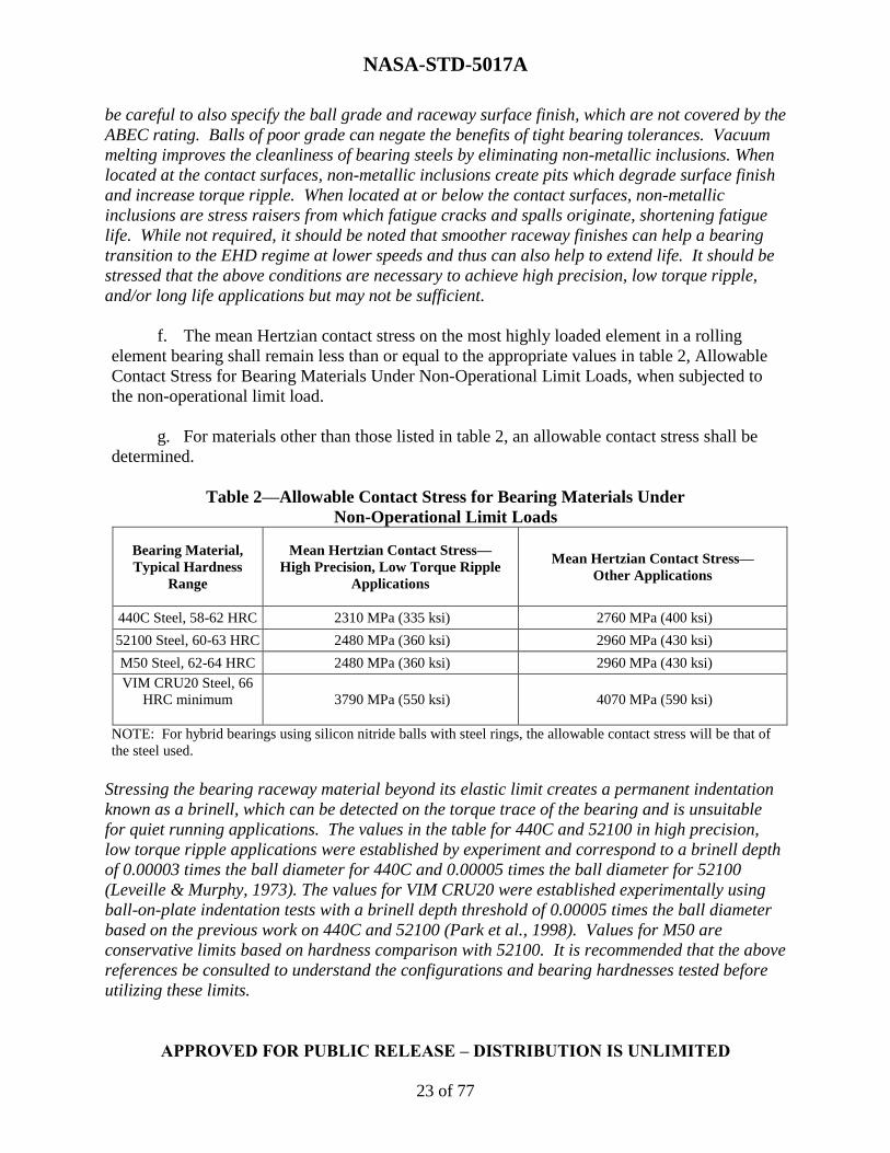
f. The mean Hertzian contact stress on the most highly loaded element in a rolling
element bearing shall remain less than or equal to the appropriate values in table 2, Allowable
Contact Stress for Bearing Materials Under Non-Operational Limit Loads, when subjected to
the non-operational limit load.
g. For materials other than those listed in table 2, an allowable contact stress shall be
determined.
Table 2—Allowable Contact Stress for Bearing Materials Under
Non-Operational Limit Loads
Bearing Material,
Typical Hardness
Range
Mean Hertzian Contact Stress—
High Precision, Low Torque Ripple
Applications
Mean Hertzian Contact Stress—
Other Applications
440C Steel, 58-62 HRC 2310 MPa (335 ksi) 2760 MPa (400 ksi)
52100 Steel, 60-63 HRC 2480 MPa (360 ksi) 2960 MPa (430 ksi)
M50 Steel, 62-64 HRC 2480 MPa (360 ksi) 2960 MPa (430 ksi)
VIM CRU20 Steel, 66
HRC minimum
3790 MPa (550 ksi) 4070 MPa (590 ksi)
NOTE: For hybrid bearings using silicon nitride balls with steel rings, the allowable contact stress will be that of
the steel used.
Stressing the bearing raceway material beyond its elastic limit creates a permanent indentation
known as a brinell, which can be detected on the torque trace of the bearing and is unsuitable
for quiet running applications. The values in the table for 440C and 52100 in high precision,
low torque ripple applications were established by experiment and correspond to a brinell depth
of 0.00003 times the ball diameter for 440C and 0.00005 times the ball diameter for 52100
(Leveille & Murphy, 1973). The values for VIM CRU20 were established experimentally using
ball-on-plate indentation tests with a brinell depth threshold of 0.00005 times the ball diameter
based on the previous work on 440C and 52100 (Park et al., 1998). Values for M50 are
conservative limits based on hardness comparison with 52100. It is recommended that the above
references be consulted to understand the configurations and bearing hardnesses tested before
utilizing these limits.

NASA-STD-5017A
APPROVED FOR PUBLIC RELEASE – DISTRIBUTION IS UNLIMITED
24 of 77
The values in the table for non-quiet running applications are based on the load that produces
brinell depths of 0.0001 times the ball diameter, as found in ABMA standards and elsewhere.
Experience shows that this brinell depth can be tolerated in most bearing applications without
affecting fatigue life.
It should be emphasized that these allowables are for non-operational loadings only, e.g.,
random vibration loads during launch, and are NOT appropriate allowables for operating stress
levels, which will generally be much lower and depend on a number of factors. See Appendix A,
for guidelines.
A yield factor of safety is used to account for uncertainty in determining the loading conditions
on bearings.
If the design limit loads are derived from mass acceleration curves, it is acceptable to analyze
the bearing using only the static loads derived from those curves.
h. Bearing fatigue life calculations shall be based on the L0.05 life when subjected to
maximum time varying loads consistent with the conditions under which the L0.05 life was
determined.
Experience indicates that the L0.05 life is sufficient to avoid fatigue life problems in life testing
and service for space applications
i. The upper and lower extremes of the ball bearing contact ellipses shall be contained
by the raceways.
Understanding the contact geometry and stress in a bearing is important for obtaining required
bearing performance and life. Truncation of the contact ellipse can cause significant increases
in stress that are not accounted for in traditional bearing analyses and can have correspondingly
large impacts on load carrying capacity and life. See Appendix A for more on contact ellipse
truncation.
j. All ball bearings shall be preloaded with the following exceptions:
(1) Four-point (gothic arch) bearings.
(2) Deep groove ball bearings for which it can be shown that the absence of preload
on the deep groove ball bearing is not detrimental to the performance of the
mechanism.
Bearing preload eliminates free play, reduces runout of the rotating member, increases axial and
radial stiffness, prevents fretting damage, reduces impact loading during vibration, increases the
load sharing among rotating elements, and prevents ball skidding. It is recognized that there are
situations in which preload is not advisable, and there are many bearing preload strategies and
considerations when analyzing the effects of preload levels and unloading of balls. See
Appendix A for guidance.

NASA-STD-5017A
APPROVED FOR PUBLIC RELEASE – DISTRIBUTION IS UNLIMITED
25 of 77
k. If axial sliding of a bearing ring is required to maintain preload, sliding shall be
facilitated by methods such as a tribological coating or a lubricated sleeve.
Some preload schemes depend on a spring and one bearing ring that is free to slide axially. In
such a case, sliding at this interface is required to achieve the desired preload and has to be
guaranteed by design.
l. Bearing preload shall be measured once all the assembly steps that establish or affect
bearing preload have been completed.
Measurement of preload needs to be verified after operations affecting bearing preload have
been completed in order to ensure that the assembly operations did not adversely affect the
preload and that the bearings function as desired in the fully-assembled configuration. It is
highly recommended that the preload be measured at intermediate levels of assembly as well.
Direct measurement is preferred but if bearing preload cannot be directly measured, indirect
methods of assessing preload, such as measurement of stiffness or Coulomb friction torque, may
be used.
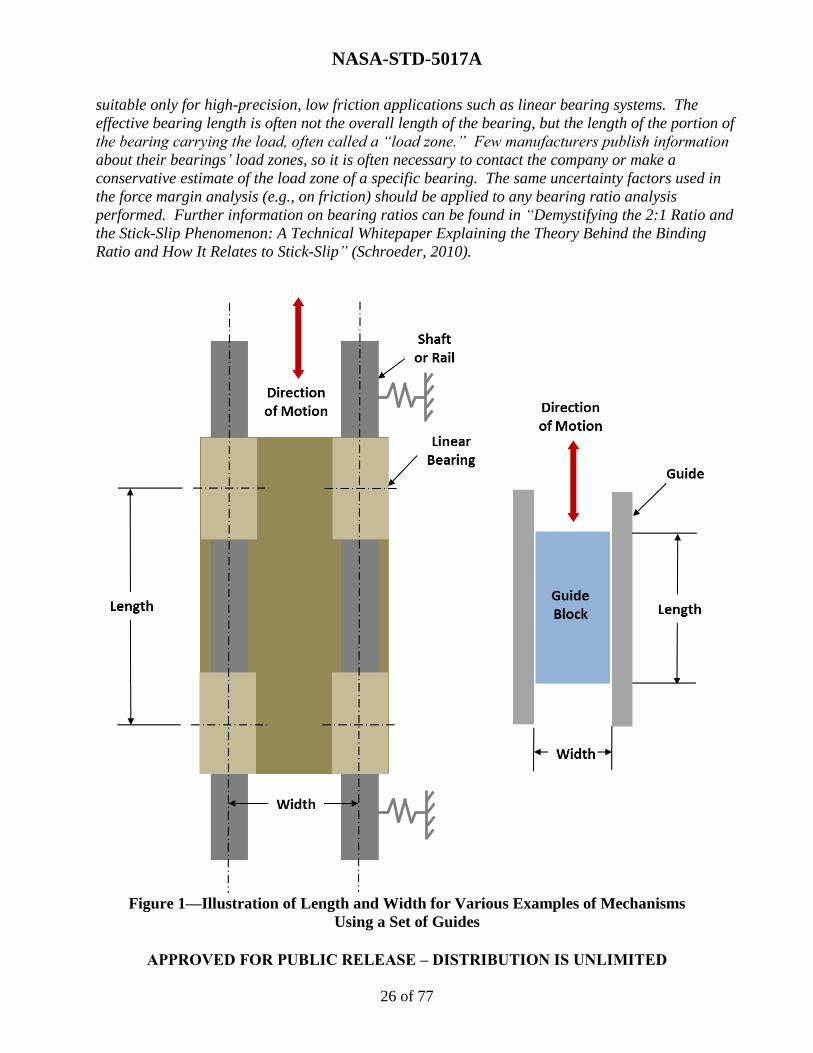
m. Mechanisms utilizing guides or linear bearings shall use a length-to-width ratio of 2:1
or greater, unless it can be shown by analysis that a length-to-width ratio of less than 2:1 will not
cause the mechanism to bind or undergo stick-slip motion taking into account the following:
(1) Possible friction coefficients.
(2) Contact forces.
(3) Actuating forces.
(4) Dynamically induced forces.
(5) Misalignments.
(6) Eccentric loading.
For mechanisms utilizing a set of linear bearings or guides, the length is defined as the distance
between guide points or bearing centers along the axis of motion and the width is the lateral
spacing between the guides or centerlines of the bearings, as depicted in figure 1, Illustration of
Length and Width for Various Examples of Mechanisms Using a Set of Guides. For
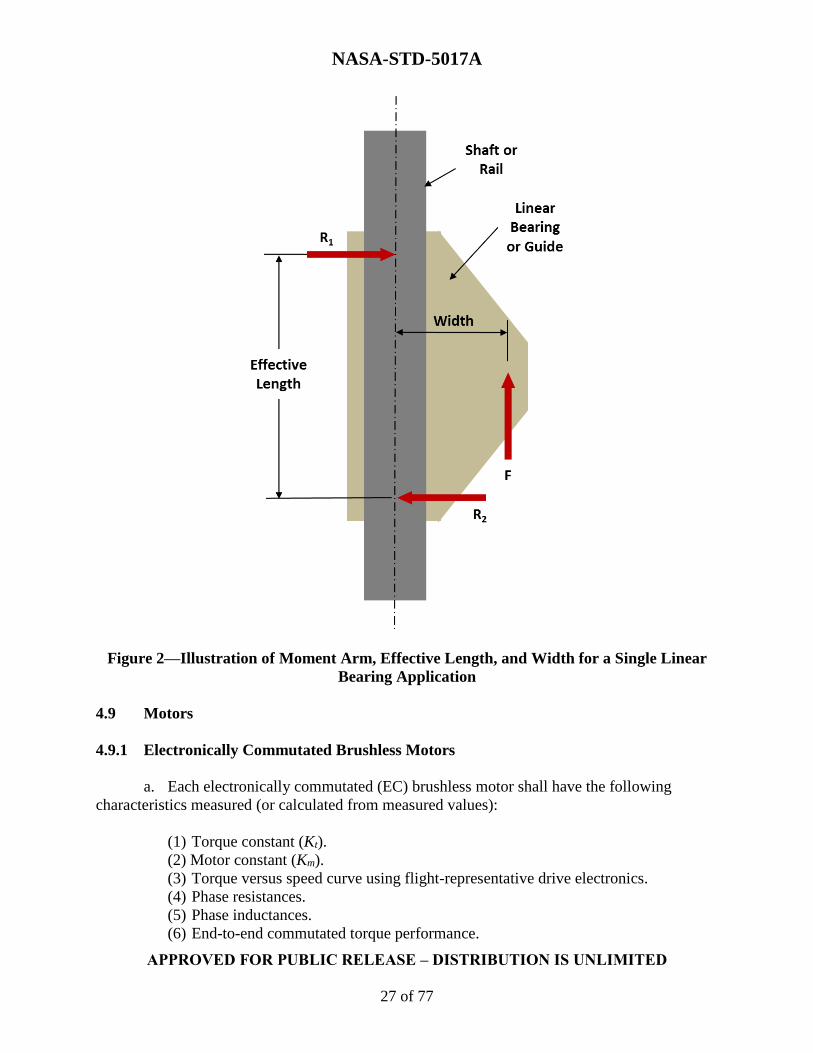
mechanisms utilizing a single linear bearing shaft or guide rail, the length is the effective length
of the linear bearing or guide and the width is the moment arm defined by the distance from the
load application point to the centerline of the rail as depicted in figure 2, Illustration of Moment
Arm, Effective Length, and Width for a Single Linear Bearing Application.
A length-to-width ratio greater than 2:1 requires no analysis. However, care should be taken
when using large length-to-width ratios within a linear bearing because shaft deflections over
the length of the bearing can also cause binding problems.
Mechanisms guided by linear devices are sensitive to the geometry of the supports. Length-to-width
ratios greater than 2:1 rarely have problems unless friction coefficients are abnormally high. Ratios
less than 2:1 can be used successfully but require careful analysis and characterization of
parameters to ensure the system does not bind or undergo stick-slip motion. Ratios less than 1:1 are
NASA-STD-5017A
APPROVED FOR PUBLIC RELEASE – DISTRIBUTION IS UNLIMITED
26 of 77
suitable only for high-precision, low friction applications such as linear bearing systems. The
effective bearing length is often not the overall length of the bearing, but the length of the portion of
the bearing carrying the load, often called a “load zone.” Few manufacturers publish information
about their bearings’ load zones, so it is often necessary to contact the company or make a
conservative estimate of the load zone of a specific bearing. The same uncertainty factors used in
the force margin analysis (e.g., on friction) should be applied to any bearing ratio analysis
performed. Further information on bearing ratios can be found in “Demystifying the 2:1 Ratio and
the Stick-Slip Phenomenon: A Technical Whitepaper Explaining the Theory Behind the Binding
Ratio and How It Relates to Stick-Slip” (Schroeder, 2010).
Figure 1—Illustration of Length and Width for Various Examples of Mechanisms
Using a Set of Guides
NASA-STD-5017A
APPROVED FOR PUBLIC RELEASE – DISTRIBUTION IS UNLIMITED
27 of 77
Figure 2—Illustration of Moment Arm, Effective Length, and Width for a Single Linear
Bearing Application
4.9 Motors
4.9.1 Electronically Commutated Brushless Motors
a. Each electronically commutated (EC) brushless motor shall have the following
characteristics measured (or calculated from measured values):
(1) Torque constant (Kt).
(2) Motor constant (Km).
(3) Torque versus speed curve using flight-representative drive electronics.
(4) Phase resistances.
(5) Phase inductances.
(6) End-to-end commutated torque performance.

NASA-STD-5017A
APPROVED FOR PUBLIC RELEASE – DISTRIBUTION IS UNLIMITED
28 of 77
These motor characteristic measurements are critical to understanding how the motor will
perform in a mechanical system. Torque versus speed testing verifies the combined performance
of the motor, feedback, and controller. This testing should use a flight-like driver and
commutation position sensor so that it is known as early as possible how the motor and motor
driver perform as a system. EC brushless motor performance can be heavily influenced by the
motor driver used to power the motor and by alignment of the commutation position sensor to
the motor.
b. The minimum measured torque output from each EC brushless motor shall be:
(1) Greater than 80 percent of peak output torque.
(2) Verified using flight-representative drive electronics.
The output torque parameters are characterized with a torque profile test. This testing is
necessary because a typical dynamometer test run will not reveal “torque holes” where the
commutation electronics switch motor current from winding to winding. A motor whose initial
position lies in one of these holes may not start under a load. See Appendix A for guidance on
torque profile testing techniques.
4.9.2 Stepper Motors
a. Each stepper motor shall have the following performance characteristics measured:
(1) Powered breakaway torque.
(2) Unpowered (detent) torque versus angle for a full rotation.
(3) Pull-in torque with representative inertia, friction loads, and step rates.
(4) Pull-out torque with representative inertia, friction loads, and step rates.
(5) Step accuracy.
(6) Detent to powered torque null alignment.
(7) Phase resistances.
(8) Phase inductances.
b. Each stepper motor shall have the rotor polar inertia calculated.
c. Stepper motor testing shall either:
(1) Use drive electronics with a pulse duration, peak voltage, and drive pulse shape
that is identical to those of the flight drive electronics, or
(2) Verify that the performance of the stepper motor is not affected by the differences
in drive pulse between test and flight drive electronics.
Stepper motors operate differently from electronically commutated brush motors so they need to
have different characteristics measured. Measuring these motor characteristics for stepper
motors allow one to understand how the motor will perform in a mechanical system. All
operational tests for stepper motors are sensitive to the inertia and stiffness of loads coupled to
the motor shaft, including measurement sensor load parameters. Reaction torque sensors are

NASA-STD-5017A
APPROVED FOR PUBLIC RELEASE – DISTRIBUTION IS UNLIMITED
29 of 77
often employed in order to minimize frictional and inertial shaft loading from the sensor;
however, the compliance of the load sensor can also impact test results.
Both pull-in and pull-out torque tests require a motor driver to perform. For similar reasons as
the brushless motor, it would be best to use a motor driver that is as flight-like as possible for
these tests. It is essential that the driver have similar characteristics for shunting diodes, output
impedance, voltage drop, current limiting and/or limited pulse width (if employed).
4.9.3 Brush Motors
a. The maximum allowable temperature limits of the motor windings and other
materials in the assembly shall be established.
b. Brush motor temperature limits shall not be exceeded for the worst operational cases
in the worst-case environments.
Brush motors are easier to overheat than other types of motors, and the temperature difference
between the windings and case, where temperature can be measured, is quite large.
Temperature margin to the motor limits should be incorporated to encompass uncertainty in the
test and/or analyses. Locked-rotor stall should be considered in the determination of maximum
temperature rise in the motor. The testing and analysis should consider the margined torque
output of the motor.
4.10 Springs
Springs shall be failure tolerant unless spring failure can be shown to be non-credible.
Springs are a common mechanism component as well as a common source of problems. Spring
redundancy can greatly improve mechanism reliability. There are two ways to achieve
redundancy in a spring, as follows: (1) a second spring can be used, (2) use of a spring that
retains functionality after one coil or element of the spring (e.g., a single conical spring in a
stack) is fractured or otherwise compromised. Note that this last option generally requires use
of a compression spring and that in the case of coil springs, the wire diameter and coil pitch
have to be such that the two spring halves cannot thread into each other after a fracture.
Determining that a spring failure is not credible requires demonstrating that adequate life and
stress margins exist on the part. This can be accomplished with a combination of stress analysis,
fatigue analysis, fracture control methods, and testing. However, given the size of many springs
used in mechanisms, fracture approaches are often not feasible and other steps have to be taken
to demonstrate reliability.
More information on spring use and design is available in Appendix A.
4.11 Gears
Gear trains shall have analysis demonstrating positive margins of safety for strength and wear,
accounting for the following conditions:

NASA-STD-5017A
APPROVED FOR PUBLIC RELEASE – DISTRIBUTION IS UNLIMITED
30 of 77
a. Tooth pitting, brinelling, and bending stresses under nominal and peak operating loads.
b. Impact tooth loads from maximum combined axial, radial, and moment loads sustained
during the full life cycle of the mechanism.
c. Backlash.
d. Effects of temperature and temperature gradients on quality of lubrication and gear
contact pattern.
e. Effects of tooth geometry.
f. Undercutting and tooth profile modifications.
g. Gear mounting, misalignment, and face load distribution.
h. Variation in operating center distance.
These parameters, which are often overlooked in design and analysis, can influence gear train
strength and wear. Verification that these factors have been accounted for is expected to include
line items for each factor in the gear train stress and wear analysis. If a particular factor does
not apply in a given situation, rationale for this inapplicability is to be provided in the analysis
documentation.
4.12 Dampers
a. Viscous dampers, including damper fluids, shall have a cleanliness requirement
established.
The cleanliness of damper components is essential due to the small clearances within a damper.
The cleanliness of damper-fluid can have a great impact on fluid performance and life, and
frequently this aspect of procurement is ignored. Verification of this requirement is expected to
include a documented plan for achieving the required cleanliness levels that are specified. It
should be stressed that cleanliness is also essential for the assembly area and tooling used.
b. All viscous dampers shall be filled while under vacuum to preclude entrapment of air.
Air entrapment in dampers can affect performance of the dampers.
c. All viscous dampers exposed to vacuum in service shall have their deadband
measured in vacuum.
Measuring the deadband in a vacuum confirms that the damper has not been underfilled and
does not contain a non-degassed damper fluid.

NASA-STD-5017A
APPROVED FOR PUBLIC RELEASE – DISTRIBUTION IS UNLIMITED
31 of 77
4.13 Separable Interfaces
a. Separation systems utilizing separation nuts or frangible nuts shall extract the bolt
without reliance upon preload or gravity.
The conversion of preload strain energy to kinetic energy of the bolt is highly dependent on
configuration and environments and is rarely reliable enough to depend upon for bolt extraction.
Similarly, because of unknowns in overall acceleration levels and the effects of dispersions in
orientation, the effectiveness of gravitational acceleration is also not dependable. Dedicated
bolt retractors or other actuation sources are necessary to ensure extraction.
b. All interfaces in deployment and jettison mechanisms designed to separate in service
shall use kickoff springs to ensure first motion unless first motion.
Joints designed to separate often experience a wide range of phenomena that can create a
tendency to keep the joint together, such as lubricant degradation, adhesion, undesirable motion
of thermal blankets, and other retarding effects. As a result, the initial separation of the joint
can be completely inhibited, force margins may be negated, or the available energy may be
consumed. Adding kickoff springs dedicated to overcoming this effect ensures that the joint will
separate and enough force or energy remains in the separation to meet requirements.
4.14 Pulleys
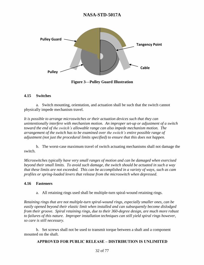
All pulleys shall use pulley guards that extend to the tangency points of the cable.
Pulley guards enclose some portion of a cable on the portion of a pulley in contact with the
cable. This prevents the cable from moving out of the plane of the pulley under a disturbance.
Making sure that the guard extends all the way to the tangency points of the cable (the points at
which the cable leaves the surface of the pulley, see figure 3, Pulley Guard Illustration) derives
the maximum benefit from the presence of the pulley guard.
NASA-STD-5017A
APPROVED FOR PUBLIC RELEASE – DISTRIBUTION IS UNLIMITED
32 of 77
Figure 3—Pulley Guard Illustration
4.15 Switches
a. Switch mounting, orientation, and actuation shall be such that the switch cannot
physically impede mechanism travel.
It is possible to arrange microswitches or their actuation devices such that they can
unintentionally interfere with mechanism motion. An improper set-up or adjustment of a switch
toward the end of the switch’s allowable range can also impede mechanism motion. The
arrangement of the switch has to be examined over the switch’s entire possible range of
adjustment (not just the procedural limits specified) to ensure that this does not happen.
b. The worst-case maximum travel of switch actuating mechanisms shall not damage the
switch.
Microswitches typically have very small ranges of motion and can be damaged when exercised
beyond their small limits. To avoid such damage, the switch should be actuated in such a way
that these limits are not exceeded. This can be accomplished in a variety of ways, such as cam
profiles or spring-loaded levers that release from the microswitch when depressed.
4.16 Fasteners
a. All retaining rings used shall be multiple-turn spiral-wound retaining rings.
Retaining rings that are not multiple-turn spiral-wound rings, especially smaller ones, can be
easily opened beyond their elastic limit when installed and can subsequently become dislodged
from their groove. Spiral retaining rings, due to their 360-degree design, are much more robust
to failures of this nature. Improper installation techniques can still yield spiral rings however,
so care is still necessary.
b. Set screws shall not be used to transmit torque between a shaft and a component
mounted on the shaft.
Tangency Point
Pulley Guard
Pulley Cable
NASA-STD-5017A
APPROVED FOR PUBLIC RELEASE – DISTRIBUTION IS UNLIMITED
33 of 77
Set screws have to be highly preloaded and dig into a shaft to work in this way, creating surface
imperfections and generating stresses that are difficult to quantify and often cannot be tolerated
in low-margin aerospace applications. In addition, repeated loading invariably leads to a
loosening of the fit as material around the set screws is deformed, regardless of whether the set
screw backs out or retains its original position.
4.17 Quick-Release Pins
Quick-release pins, sometimes referred to as “pip-pins,” shall be considered individual
mechanisms and are subject to the requirements established in this document.
Quick release pins were originally designed for ground applications but because of their ease of
use have seen use in space flight applications, particularly in human-rated spacecraft. The pins
themselves are small mechanisms and subject to common mechanical and structural failure
modes. Most off-the-shelf pins are not designed to withstand space flight environments and past
use has resulted in a wide array of problems with virtually every component of the pins. Quick
release pins can be used successfully if designed expressly for this purpose and subjected to the
same rigor as any other mechanism though they are never recommended for zero-fault-tolerant
applications. See Appendix A for more information.
4.18 Released Degrees of Freedom
Interfaces designed to release mechanical degrees of freedom shall be considered mechanisms
subject to the requirements established in this document.
Features whose sole purpose is to release degrees of freedom (e.g., spherical bearings in struts)
are actually mechanisms and subject to failure modes typical of mechanisms, despite their
structural appearance. These interfaces are often overlooked when mechanism requirements are
applied and verified.
4.19 Threaded Interfaces
Threaded interfaces designed to be actuated in service shall be considered mechanisms subject to
the requirements established in this document.
Actuated threaded interfaces (e.g., crew-actuated bolts assembling space station components)
are actually mechanisms and subject to failure modes typical of mechanisms, despite their
structural appearance. These interfaces are often overlooked when mechanism requirements are
applied and verified. Past oversights of this kind have led to high-profile failures in service.

NASA-STD-5017A
APPROVED FOR PUBLIC RELEASE – DISTRIBUTION IS UNLIMITED
34 of 77
4.20 Heritage Mechanisms
The design of previously qualified mechanisms or mechanism components shall undergo a
qualification program for use in a new application unless all environments of the new application
are enveloped by the environments of the previous application.
The use of part designs or entire mechanism designs that have been qualified for another
purpose, commonly referred to as “heritage hardware,” is often encouraged due to perceived
savings in cost and schedule. Great care has to be exercised in utilizing such hardware or the
anticipated savings can quickly disappear. One of the most common mistakes is selecting a
design that was qualified for an environment that is not enveloped by all of the new environments
but failing to re-qualify the design for the new environment. In practice, it is difficult to find
designs that can truly be said to be previously qualified for a new application because of the
wide variety of unique environments and missions encountered by spacecraft. Even if certain
environments are enveloped, the effect of the environment on the performance of the mechanism
would be missed if it were not included in the qualification program.
The extent of the qualification program for the new application is left for the responsible
engineering organization to determine. Depending on the application, an appropriate
requalification could range from a delta qualification to a full requalification.
4.21 Performance Testing
All mechanism functions shall be exercised during performance testing.
Sometimes there is a desire to test only critical functions or nominal operations, but all functions
of the mechanism have to be tested in order to verify performance of the system, including back-
up or redundant provisions. This applies regardless of whether the performance testing is
conducted during qualification, life, or acceptance testing.
4.22 Qualification Testing
a. Each mechanism design shall be subjected to environmental qualification testing that
exposes the mechanism to all environments that it will experience in service.
Qualification testing ensures that the design is sufficient to meet the requirements of the
mechanism, with margin, in the operating environments it is expected to experience. The types
of environmental qualification testing required for mechanisms are typically established by the
program. A recommended set of tests is included in Appendix A. The program also typically
specifies required margin, test order, tolerances, and general methods to be used. Behavior
under environmental conditions can be very hard to predict and omission of qualification testing
can significantly increase the risk of in-service failure.
b. All service configurations of the mechanism shall be subjected to environmental
qualification testing in the mechanism’s appropriate operating or non-operating state.

NASA-STD-5017A
APPROVED FOR PUBLIC RELEASE – DISTRIBUTION IS UNLIMITED
35 of 77
The hardware configuration (e.g., launch, on-orbit, landing) can affect many aspects of the
system such as load path, stiffness, clearances, slop in joints, and radiative view factor. It is
important that the qualification testing be performed on the mechanism while the mechanism is
in the configuration in which it will experience the environments and perform its functions,
otherwise differences such as those stated may cause the unit to behave differently in test than it
would in service, leading to false confidence in the hardware or unrealistic test failures.
c. Mechanism qualification testing shall be conducted with mounting interface boundary
conditions that replicate the flight boundary conditions, including the following:
(1) Stiffness.
(2) Mounting alignment and tolerances.
(3) Thermal distortions.
(4) Load-induced distortions.
Testing with improper representation of boundary conditions can give misleading results due to
factors such as additional loads, different frequency response, and extra joint slop. Appropriate
boundary conditions can sometimes be difficult to implement in test and compromises often have
to be made between interface fidelity and the level of assembly needed to achieve good fidelity.
Verification that these influences have been accounted for is expected to include explicit
description of how these boundary conditions are addressed in the test plan, or if the condition
does not apply in a given situation, the rationale for this inapplicability.
d. Qualification units shall utilize flight-life electronics.
Using different drive electronics than will be used in flight can generate non-flight-like behavior,
which may give false confidence in the performance of the mechanism. For this reason, the
qualification test units, including the life test unit, has to utilize drive electronics with the same
characteristics as the flight unit. Care also should be taken to consider the configuration and
lengths of harnessing and the software used as they may affect performance.
e. Inspections shall be conducted both at the start of qualification testing and at the
conclusion of qualification testing.
f. Performance tests shall be conducted both at the start of qualification testing and at
the conclusion of qualification testing.
Pre-test performance tests and inspections establish baseline condition and performance. Post-
qualification performance tests and inspections allow the residual effect of the environmental
test to be determined when compared to the pre-test baseline. At a minimum, one post-test
performance test and inspection should be performed at the end of the suite of qualification tests,
but additional tests or inspections inserted into the test flow, for example between random
vibration testing and thermal-vacuum testing, or even between axes of random vibration tests,
allow for easier identification of a problematic environment when anomalies occur.
NASA-STD-5017A
APPROVED FOR PUBLIC RELEASE – DISTRIBUTION IS UNLIMITED
36 of 77
g. Pass-fail criteria and rationale for those criteria shall be established for all
qualification tests prior to the start of qualification testing.
h. Inspection procedures for all qualification tests shall be established prior to the start
of qualification testing.
Pass-fail criteria and inspection procedures have to be established prior to testing to avoid
rationalization of anomalous behavior detected during testing. This also helps streamline the
decision making and documentation process when anomalies are encountered during the test.
4.22.1 Design Life Testing
a. Design life testing shall be performed on all mechanism functions to verify that all
design life requirements have been met.
Sometimes there is a desire to test only certain functions or nominal operations, but all functions
of the mechanism have to be life tested in order to verify life of the system, including back-up or
redundant provisions. Typical design life concerns include fatigue limits, deterioration of
lubrication, excessive wear, and deterioration during extended quiescent periods. See Appendix
A for more guidance on design life testing.
b. Mechanisms whose failure could result in a loss of human life shall be life tested to a
number of cycles no less than four times the total of all operational cycles plus the total of all
ground cycles (including test cycles, installation cycles, and maintenance cycles).
c. All other mechanisms shall be life tested to a number of cycles no less than two times
the total of all operational cycles plus the total of all ground cycles (including test cycles,
installation cycles, and maintenance cycles).
The life test factor is intended to address mechanical life and wear concerns, not vibration and
fatigue life concerns, though in certain cases, the mechanical motion and life are driven by
vibration and the cycle count and magnitudes have to be derived from the vibration environment.
It is highly recommended that spare cycles be added to the total cycles required to allow
troubleshooting or execution of extra cycles without exceeding the mechanism's certified life.
An example calculation for determining the total number of cycles required in the life test
follows:
A filter wheel mechanism with a mechanical detent used on an orbiting observatory is required
to perform 1500 cycles over its life. It undergoes run-in testing, one cycle of initial performance
testing, one cycle of performance testing after the random vibration test, one cycle of
performance testing at each hot and cold extreme of a thermal-vacuum test comprised of four
hot-to-cold excursions, and one cycle of performance testing prior to flight. The design lead
wishes to incorporate ten contingency cycles as margin for unexpected actuations. How many
cycles have to be applied to the life test unit in order to meet the life test requirement?

NASA-STD-5017A
APPROVED FOR PUBLIC RELEASE – DISTRIBUTION IS UNLIMITED
37 of 77
Run-in of the example mechanism requires 5 percent of the operational cycles, in this case 75
cycles. The rest of the tests add another 11 cycles. There are no other cycles required for
installation, maintenance, or any other activity, so the total number of cycles expected on the
mechanism is 1586 and 10 cycles of margin brings the final total to 1596 cycles. The failure of
the filter wheel is not safety-critical, so the total number of cycles is multiplied by 2. The
resulting number of required cycles in the life cycle test is therefore 3192 cycles.
d. Design life verification testing shall include a number of cycles at the expected
operating environmental extremes, loads, and speeds that is representative of the number of
cycles at those conditions expected in the service life of the mechanism.
Temperature and vacuum conditions can both have significant effects on component life due to
effects on lubrication, friction, and material properties. Not properly including these
environments in the life tests can lead to test results that are not indicative of how the hardware
will perform in service. Appendix A contains recommendations on how to allocate cycles of the
life test to different environments.
e. The design life test shall include functioning bearings under the maximum predicted
operational contact stress for the number of cycles predicted in flight multiplied by the
appropriate life test factor.
Bearing life is highly dependent on contact stress, thus it is necessary to ensure that flight-like
contact stresses are present in the life test to avoid misleading test results.
f. Design life verification testing shall include testing of mechanical stops by
intentionally running the mechanism into the stops during each test cycle.
Mechanical stops perform a function of the mechanism and have to be life tested. Often
mechanical stops are not contacted under nominal testing conditions and so their ability to
withstand loading over the life of the mechanism may not be evaluated in ground testing.
However, in service, conditions may be such that the stops are contacted consistently regardless
of whether or not the mechanism reached its mechanical stops during ground testing. For this
reason, the mechanical stops have to be intentionally tested during a life test. In some cases
where stops are not normally contacted due to the use of software stops or other means, it may
be impractical to run the mechanism into the stops during the design life test of the assembly. In
these situations, life testing of the stops may be conducted separately at a subassembly level.
g. The life test shall be performed on the environmental qualification unit.
Performing the life test on the environmental qualification unit helps ensure that environmental
effects on the mechanism life are accounted for.
h. A performance test shall be conducted during both the first and last cycles of the
design life test.

NASA-STD-5017A
APPROVED FOR PUBLIC RELEASE – DISTRIBUTION IS UNLIMITED
38 of 77
Pre-test performance tests and inspections establish baseline condition and performance. Post-
test performance tests and inspections allow the residual effect of the design life test to be
determined when compared to the pre-test baseline.
i. Inspection procedures and pass-fail criteria for design life test and performance tests
shall be established prior to the start of design life testing.
Inspection procedures and pass-fail criteria have to be established prior to testing to avoid
rationalization of anomalous behavior detected during testing. This also helps streamline the
decision making and documentation process when anomalies are encountered during the test.
4.23 Acceptance Testing
a. Each mechanism shall be subjected to environmental acceptance testing that exposes
the mechanism to all environments that it will experience in service.
Acceptance testing ensures that the individual hardware build is sound and capable of meeting
its performance requirements in the operating environment it is expected to experience. The
types of environmental acceptance testing required for mechanisms are typically established by
the program. A recommended set of tests is included in Appendix A. The program also typically
specifies required margin, test order, tolerances, and general methods to be used. Omission of
acceptance testing can significantly increase the risk of in-service failure.
b. All service configurations of the mechanism shall be subjected to environmental
acceptance testing in the mechanism’s appropriate operating or non-operating state.
The hardware configuration can affect load path, stiffness, clearances, slop in joints, radiative
view factor, and many other aspects of the system. It is important that the acceptance testing be
performed on the mechanism while the mechanism is in the configuration in which it will
experience the environments and perform its functions, otherwise differences such as those
stated may cause the unit to behave differently in test than it would in service, leading to false
confidence in the hardware or unrealistic test failures.
c. A run-in test shall be performed on each mechanism prior to undergoing any other
acceptance testing.
Run-in testing (also known as wear-in testing) serves two purposes. First, it acts as a screen to
detect material and workmanship defects that manifest themselves early in the mechanism’s life.
Second, it allows the mechanism to work through initial transient behavior and reach steady-
state performance. This allows for a better understanding of mechanism performance and easier
observation of trends and detection of anomalies. If performance metrics do not appear to be
leveling off, trends are not as expected, or performance levels are not as anticipated, this may be
an indication of failure. Sufficient data has to be obtained during the run-in test to allow
determination of these important performance characteristics and their trends. Without
sufficient data, for example, high enough sample frequency, actual trends may be masked. In

NASA-STD-5017A
APPROVED FOR PUBLIC RELEASE – DISTRIBUTION IS UNLIMITED
39 of 77
addition, measurements of important parameters should be made as directly as possible to help
avoid ambiguous results.
d. The run-in test shall be conducted for at least 15 cycles or 5 percent of the total
expected service life, whichever is greater, unless the mechanism has demonstrated the capability
to perform in a consistent and controlled manner with fewer cycles.
These run-in durations have been shown through experience to be adequate for achieving the
goals of the testing. However, it may not be sufficient in all situations. If performance metrics
do not appear to be leveling off or friction levels have not been reduced to a desired level at the
conclusion of the run-in test, continued run-in may be warranted. For this reason, among
others, it is recommended to include margin in the number of cycles used in calculating the
design life for the mechanism. The definition of what constitutes a cycle is application-
dependent and has to be determined on a case-by-case basis.
e. The run-in test conditions shall be representative of the operational loads, speed, and
environment.
Running-in using conditions other than those expected in service can produce data during the
test that is not indicative of true performance or can even damage hardware. For example,
running-in at a different speed than anticipated in service can change the lubrication regime in a
bearing and running-in a molybdenum disulfide dry film lubricant at ambient pressure can
generate excessive wear of the lubricant and inaccurate friction values. If a variety of
environments are expected in service, a split similar to that recommended in Appendix A should
be used. This requirement is not intended to require application of all environments
simultaneously.
f. Inspection and performance tests shall be conducted after run-in testing prior to
further acceptance testing, and at the conclusion of acceptance testing.
Pre-test performance tests and inspections establish baseline condition and performance. Post-
test performance tests and inspections allow the residual effect of the environmental test to be
determined when compared to the pre-test baseline. Unlike inspections after qualification
testing, the post acceptance inspections have to be made without disassembly or other breaking
of configuration. At a minimum, one post-test performance test and inspection should be
performed at the end of the suite of acceptance tests, but additional tests or inspections inserted
into the test flow, for example between random vibration testing and thermal-vacuum testing, or
even between axes of random vibration tests, allow for easier identification of a problematic
environment when anomalies occur. Be sure to account for these performance tests when
calculating the required design life of the mechanism.
g. Pass-fail criteria, the rational for those criteria and inspection procedures for all
acceptance tests shall be established prior to the start of acceptance testing.

NASA-STD-5017A
APPROVED FOR PUBLIC RELEASE – DISTRIBUTION IS UNLIMITED
40 of 77
Inspection procedures and pass-fail criteria have to be established prior to testing to avoid
normalization of anomalous behavior detected during testing. This also helps streamline the
decision making and documentation process when anomalies are encountered during the test.
4.24 Mechanism Installation
Mechanisms shall either be designed to preclude installation in an incorrect orientation or be
clearly labeled in a manner that indicates proper installation orientation.
There have been incidents in the past wherein mechanisms whose correct installation orientation
is not overtly obvious have been installed improperly, because the interface allowed this to
happen. To prevent this, features such as keys or asymmetric mounting patterns should be
utilized whenever possible. If such provisions are not possible or practical, the hardware has to
be at least labeled in such a way that makes improper orientation obvious. Drawing notes or
other procedural controls that are not present on the hardware are not as effective and are not
considered sufficient.

NASA-STD-5017A
APPROVED FOR PUBLIC RELEASE – DISTRIBUTION IS UNLIMITED
41 of 77
APPENDIX A
BEST PRACTICES FOR MECHANISMS
A.1 Purpose
The purpose of this appendix is to present best practices for the design, development, and testing
of aerospace mechanisms. The contents of this appendix do not constitute requirements that
have to be followed in order to adhere to this Standard, but rather practices that past experience
has shown to create the maximum potential for successful mechanism operation in service,
pitfalls to recognize and avoid, and background information to enhance understanding of the
requirements in section 4.
A.2 Best Practices
A.2.1 Torque and Force Margins
When determining torque or force margins on electromagnetic actuators such as motors or
solenoids, one must consider magnetic saturation effects to obtain an accurate calculation of
margin in cases where measurement of output at the worst-case operating condition cannot be
made. A common mistake is to assume that the relationship between output torque or force and
voltage or current is linear throughout the range of operation, which does not account for the
non-linear shape of the magnetization curve. Figure 4, Illustration of the Effect of Saturation on
Actuator Output, illustrates how the assumption of linear behavior can lead to incorrect output
calculations.
Figure 4—Illustration of the Effect of Saturation on Actuator Output

NASA-STD-5017A
APPROVED FOR PUBLIC RELEASE – DISTRIBUTION IS UNLIMITED
42 of 77
Energy margin is an additional value that is sometimes calculated for mechanisms. If
torque/force margin requirements are followed through the entire range of motion of a
mechanism, it is unnecessary to calculate energy margin. All the energy in the world will not
move a mechanism if insufficient force is available. However, an application for energy margin
occasionally arises such as when evaluating pyrotechnic device performance or in special cases
where sufficient torques or forces cannot be applied over the entire range of motion of the
mechanism and the mechanism energy needs to be assessed while coasting through this
unpowered phase.
If it becomes necessary to evaluate energy margin, equation 4-1 may still be used. In these
situations, “Energy” replaces “Torque” in the equation and descriptions. Eavail represents the
total stored energy in the system that is available to do work, Ef is typically the energy required
to accelerate a mass at a given rate or to a given velocity, and Ev is typically energy dissipated by
nonconservative forces in the system. Energy margin should, of course, be greater than zero, but
given the risky nature of relying upon energy margin, a higher value is often warranted to ensure
that the mechanism retains reserve energy that can be applied in the event of an unforeseen effect
that dissipates energy from the mechanism.
A.2.2 Lubrication
Lubricant selection for space mechanisms is an important consideration and often dictates the
performance lifetime of a given application. The best and most direct method for determining
lubricant life is by performing life testing in a relevant flight-like environment. Stress cycle
analysis is often employed as an empirical approach to quickly assess lubricant life. Bearing life
is best predicted by performing stress cycle analysis on the lubricant used in the bearing and is
more useful than fatigue life predictions since with current technology it is lubricant life, and not
fatigue life, that dictates bearing performance and lifetime.
While there are many lubricants available commercially, few have been qualified in space where
vacuum conditions and wide temperature extremes preclude most lubricants from consideration.
There are two basic types of lubricants to consider: wet lubricants (i.e., oils and greases) and
solid lubricants. In general, wet lubricants are preferred for most space applications provided
that the thermal environments of the application fall within the performance specification of the
lubricant. Solid lubrication is often selected when wet lubricants are unable to meet the thermal
conditions specified for a given application (e.g., cryogenic environments), although many
applications have employed solid lubrication over wet lubrication for various reasons. Care
should be taken to specify the proper amount of lubricant to be applied. While the effects of too
little lubrication may be obvious, excessive lubrication can also cause problems such as high
forces or torques due to viscous effects or reduced clearances. Regardless of the lubrication
chosen, metal-to-metal tribological contacts should be composed of dissimilar materials
whenever the application allows.
When considering wet lubrication, the selection of grease versus oil is important. The
composition of grease consists of a base oil that may contain additives and a thickening agent
used to form the bulk. Grease is often preferred to oil because of its ability to maintain an oil
supply at a given location versus the tendency of oil to creep and migrate. Grease consistency is

NASA-STD-5017A
APPROVED FOR PUBLIC RELEASE – DISTRIBUTION IS UNLIMITED
43 of 77
affected by the quantity of oil present in a formulation and hence is critical in determining how
the lubricant will perform in a given application. A typical consistency for commercially
available grease is designated as National Lubricating Grease Institute (NLGI) grade 2, however
other consistencies exist. One important point to note is that grease consistency can be adjusted
by varying the quantity of oil present in the formulation. NLGI grades higher (stiffer) than
NLGI grade 2 can be obtained by using less oil in the grease formulation, while NLGI grades
lower (softer) than NLGI grade 2 can be obtained by using more oil in the formulation. To
illustrate the importance of this point, consider a high-speed ball bearing application where the
high-speed bearing is lubricated with grease. If the consistency of the grease is such that the
grease slumps, falling behind each ball as it passes around the bearing raceway, the balls have to
continuously perform work on the grease in order to push the grease out of their path. This
causes a drag torque and results in elevated heating. If, on the other hand, the grease is stiffer
and forms a channel as the balls pass around the bearing, the balls will not encounter large
quantities of grease in the track. This scenario would produce low drag and reduced heating. It
is not surprising that high-speed bearings typically prefer channeling greases to their non-
channeling counterparts. Gears can be problematic applications because there is an appreciable
amount of sliding that occurs as the gear teeth mesh. Greases employed on gears need to have
proper consistency so that they can adhere to the gear, but can also reflow back into the contact
zone and reestablish lubrication. For this reason, it is often desirable to use softer greases such
as NLGI grade 1, although NLGI grade 2 is still almost exclusively used in space applications.
The takeaway regarding consistency is that it matters, as it is the consistency that maintains and
distributes the supply of oil, and that every application may be suited to different consistency.
Unfortunately, testing is often necessary to deduce effects attributed to consistency, but if
properly addressed, application performance and lifetime can be maximized.
When grease and oils are employed for lubrication, barrier films are normally applied to adjacent
surfaces to retain oil where desired, prevent oil creep, and to protect sensitive areas from
contamination. Oils have very low surface tensions as compared to the surface energies of solids,
and it is for this reason that oils wet (spread) on solids when applied. Wetting is prevented when
contamination or boundary films of lower surface tension than the lubricating oil are present.
Barrier films are very low surface tension solids such as perfluoropolymethacrylates that are
dispersed or dissolved in a carrier solvent and are typically applied by brushing or dabbing
surfaces and allowing the solvent to evaporate. Areas coated with barrier film are rendered
unwettable since oils have higher surface tensions than the barrier film. However, barrier
coatings may be less effective with perfluoropolyalkylether- (PFPE) based lubricants than with
hydrocarbon-based lubricants because of the lower surface tension of PFPEs compared to
hydrocarbon lubricants. Barrier films may still provide some creep protection with PFPEs and
require case-by-case evaluation.
Any lubricant selected for a given application has the potential to cause harm as a contaminant.
All wet lubricants have some volatility that has the potential to contaminate optics or other
sensitive components. The consultation of a contamination engineer is strongly encouraged
when assessing lubricant volatility. Volatile components can also form friction polymers in
undesired locations such as electrical contacts and moving parts, although this is less common
with the use of modern low-outgassing materials. Analysis and testing may be necessary to
reduce risks associated with volatile contamination. Per NASA-STD-6016, Standard Materials
NASA-STD-5017A
APPROVED FOR PUBLIC RELEASE – DISTRIBUTION IS UNLIMITED
44 of 77
and Processes Requirements for Spacecraft, NASA uses the testing method of ASTM E595,
Standard Test Method for Total Mass Loss and Collected Volatile Condensable Materials from
Outgassing in a Vacuum Environment, to evaluate the volatility of materials, including lubricants
intended for space applications. Contamination arising from oil creep should also be considered.
As discussed previously, a common best practice to reduce risks associated with creep is to
introduce barrier films at appropriate locations to prevent oil from migrating to sensitive areas
while maintaining the oil in the location desired for lubrication performance. Care should also
be taken to ensure that the vent paths from volumes containing liquid lubricants do not impinge
on critical surfaces.
An additional consideration is contamination of the lubricant itself. During the manufacture and
handling of wet lubricants, it is not uncommon to encounter metallic debris and other soft
particulate matter. All wet lubrication intended for spaceflight should be filtered to remove
contaminants and avoid their introduction into the application during lubrication. Oils should be
filtered through 0.10 micron filters and grease should be filtered through 0.25 micron filters.
Once filtered, lubricants should be handled and introduced into the application under controlled
conditions (e.g., clean room, class 100 flow bench).
The two classes of wet lubricants commonly employed for space applications are hydrocarbons
and PFPEs, although other chemistries such as esters have been flown. Synthetic hydrocarbons
including Pennzane®, a multiply alkylated cyclopentane (MAC) oil, and polyalphaolefins are
typically encountered in modern space applications versus their non-synthetic higher vapor
pressure counterparts, although applications persist in which oil reservoirs are employed to
provide a long-term supply of oil, such as the International Space Station (ISS) control moment
gyroscopes (CMGs), which are lubricated with KG-80 oil. In general, under equivalent
conditions, hydrocarbons will outperform PFPEs with respect to operating lifetime for a given
application where lifetime is quantified in terms of stress cycles. Lubricant consumption is
normal and occurs in all tribological contacts. In chemical terms, hydrocarbons are consumed in
the tribocontact at a slower rate than their PFPE counterparts. PFPEs should be avoided when
lubricating aluminum or titanium surfaces, especially those operating in the boundary lubrication
regime where sliding or fretting is anticipated. These metals are notorious for their rapid
degradation of the PFPE backbone via Lewis acid catalyzed degradation, a well-established
degradation pathway for PFPEs.
While each application should be considered independently, there are some general rules of
thumb that can be employed when considering lubrication for a given application. Boundary
lubrication occurs when there is intimate asperity contact between moving parts. Examples of
boundary lubrication applications include gears and bearings operating at slow speeds, sliding
contacts, and rollers. These applications typically are best served by employing synthetic
hydrocarbons formulated with boundary additives, often referred to as anti-wear additives.
Commonly employed boundary additives used in space formulations include phosphate esters of
varying composition possessing low vapor pressure to prevent evaporation in a vacuum.
Phosphate esters also afford some corrosion protection and are superior to PFPEs in this regard.
The higher molecular free volume of PFPEs compared to hydrocarbons renders the PFPE more
susceptible to permeation by water and hence corrosion of metallic surfaces. Care should be
taken with respect to corrosion when using alloys such as 52100 steel and hardened tool steels
NASA-STD-5017A
APPROVED FOR PUBLIC RELEASE – DISTRIBUTION IS UNLIMITED
45 of 77
such as M-50 and Crucible 20. These alloys are typically best served by coating them with
hydrocarbon oils containing corrosion inhibitors.
PFPEs typically suffer from rapid degradation in boundary conditions when oil-soluble anti-wear
additives are absent. Molybdenum disulfide is one boundary additive frequently used in PFPE
formulations. Polytetrafluoroethylene (PTFE) present as a thickener in PFPE formulation also
affords some boundary protection, but experience has proven that it often fails to prevent the
PFPE oil from degrading under harsh boundary conditions. PFPEs typically see service when
thermal environments to be witnessed by a given application fall below -20 °C. In these
situations, hydrocarbons cannot be employed unless heaters are present rendering PFPEs as the
only wet option available. One drawback to the use of PFPEs is the tendency of the oil to creep.
When compared to a hydrocarbon, the flow activation energy for a PFPE is approximately one
half that of a hydrocarbon resulting in about twice the tendency to flow. One advantage to
PFPEs is the superior vapor pressure and decreased volatility. As stated earlier, PFPEs are
typically less stable in the tribological contact for a given set of stress cycles. PFPEs have a
much better viscosity index and are stable at temperatures approaching 200 °C versus their
hydrocarbon counterparts that are thermally stable up to about 120 °C. On the cold side, PFPEs
have been known to perform down to the -60 °C to -70 °C range depending upon the application.
The superior vapor pressure and thermal performance of PFPE are largely responsible for their
wide use in space applications, despite the drawbacks cited earlier. PFPEs are also known for
their compatibility with various elastomers and polymers, often employed on gaskets and o-rings
to enhance sealing and prevent binding. MIL-PRF-27617, Grease Aircraft and Instrument Fuel,
and Oxidizer Resistant, specifies performance requirements for PFPEs.
High speed applications operating in the EHD regime have benefited greatly from the use of
synthetic hydrocarbons versus their non-synthetic counterparts due in part to their improved
thermal stability, i.e., lower vapor pressure, but synthetic hydrocarbons have lower pressure-
viscosity coefficients resulting in thinner EHD films when compared to their non-synthetic
counterparts, e.g., Pennzane® versus Coray 100®. Pennzane®-based lubrication (oil or grease) is
now commonly used in virtually all high speed bearing applications including reaction wheels
and control moment gyroscopes operating in the EHD regime. One notable exception cited
earlier is ISS CMGs, which are lubricated with an active oiler using KG-80 oil.
Solid lubricants include dry-film lubricant (DFL) and other sacrificial solid materials such as
gold, silver, and lead. When using dry-film lubricant such as molybdenum disulfide, proper
attention to surface preparation and cleanliness should be given. Considerations for polymer-
bound DFLs are noted in MIL-PRF-46010, Lubricant, Solid Film, Heat Cured, Corrosion
Inhibiting. This specification describes surface preparation, application of lubricant, and
associated performance requirements for properly applied and adherent films. When using
sputtered and physical chemical vapor deposited (PCVD) forms of DFL, the substrates are
typically pre-sputtered in vacuum with argon to ensure adventitious carbon and metal oxides are
removed prior to application of the lubricant. Failure to properly prepare surfaces prior to
application of any form of DFL will result in poor adhesion. The same is also true for deposition
of metallic films.

NASA-STD-5017A
APPROVED FOR PUBLIC RELEASE – DISTRIBUTION IS UNLIMITED
46 of 77
The use of metal dichalcogenides such as molybdenum disulfide require special consideration of
humidity effects. In general, the polymer-bound form of molybdenum disulfide is the most
stable and least sensitive to negative performance effects attributed to exposure to humid
environments. Polymer-bound forms of DFL are less crystalline and have limited reactive edge
sites available for reaction with water. Other polymer-bound formulations not conforming to
MIL-PRF-46010 exist including those polymer-bound forms that are prepared by electrophoretic
methods. Polymer-bound forms of DFL typically result in thicknesses around 12 microns
(0.0005 in). Burnished (mechanically applied) and physical chemical vapor deposited forms of
molybdenum disulfide are thinner 0.25 to 0.5 micron films and are highly crystalline forms
possessing reactive edges sensitive to humidity exposure. Pure sputtered molybdenum disulfide
coatings can also exhibit sensitivity, but these have been replaced in most applications with co-
sputtered nanocomposite molybdenum disulfide coatings containing nickel or antimony oxide
that are considerably more robust with respect to humidity.
When molybdenum disulfide is exposed to humidified air, there is a conversion at the surface to
molybdenum trioxide, a higher friction material. This brittle oxide possesses a higher coefficient
of friction and will be present until it is worn away, resulting in a net loss of original
molybdenum disulfide film. Therefore, operation in humid environments is not recommended
and should be minimized if such loss is a concern. Exposure to humidified environments
without operation results in conversion to the oxide and a higher coefficient of friction that will
not recover until the oxide is worn away. For this reason, molybdenum disulfide films should be
stored in anhydrous environments whenever possible, including the use of dry inert gas purging
(e.g., dry nitrogen). Slip ring brushes based on molybdenum disulfide are especially vulnerable
because oxidation products create electrical noise. It is, therefore, recommended that slip ring
assemblies be designed with a built-in nitrogen purge port to allow internal purging. In addition,
inorganic binders (phosphates and silicates) are sometimes used with DFLs. Because these
binders themselves are hygroscopic, temperature and humidity should be controlled to ensure
that the DFL does not soften or produce atmospheric reaction products (e.g., sodium carbonate)
that can impede performance.
Polymer-bound forms of molybdenum disulfide are well known to generate debris as the DFL
coating is burnished under the applied loads and cycles witnessed by the application. For this
reason, pre-burnishing or run-in is normally performed where the application is subjected to
some predetermined number of cycles to orient the lamellar planes of the DFL and the debris that
accompanies the burnishing process. Once a steady state is achieved and debris generation is
minimized, it is desirable to clean the application to remove the debris generated in the run-in, if
possible. In all cases where polymer-bound DFL is employed, debris generation should be
considered when assessing the life and performance of the application. The potential for
negative effects attributed to the DFL debris such as contamination of optics or other debris
sensitive components, including electronics should be considered. Sputtered and PCVD coatings
tend to generate a lesser quantity of debris (though the particle count may be higher).
NASA-STD-5017A
APPROVED FOR PUBLIC RELEASE – DISTRIBUTION IS UNLIMITED
47 of 77
A.2.3 Bearings
Bearings are common and frequently critical components in mechanical systems. As simple as
they may seem, bearings can be a challenge to properly design and implement in a mechanical
system. The body of knowledge on bearings is vast and continually increasing, and while a
thorough treatment of bearings would require many volumes of text, this section presents some
of the more important best practices for the selection, sizing, preloading, analysis, lubrication,
and implementation of bearings within a space mechanism.
A.2.3.1 Ball Bearings
A.2.3.1.1 Ball Bearing Selection
The selection of a ball bearing can depend on many elements. The most common considerations
are load capacity, stiffness, drag torque characteristics, life, and sometimes material
compatibility and thermal characteristics.
Many factors influence the drag torque characteristics of a ball bearing, including applied load,
preload, fits, ball complement, component precision, temperature, cage material and style, and
lubricant. Bearing size also has a direct effect; all other influences being equal, a larger diameter
bearing will have a higher drag torque.
The two most commonly encountered types of ball bearings are deep groove ball bearings and
angular contact bearings. Deep groove ball bearings (also called radial bearings or Conrad
bearings) are intended for applications where radial load capacity is the primary concern;
however, they can accommodate limited axial loads as well. Deep groove ball bearings are
designed with a radial clearance. For a given conformity, a larger radial clearance will result in a
higher axial stiffness and correspondingly lower radial stiffness because of the larger effective
contact angle that is created when loaded.
Angular contact ball bearings support both a radial and axial load. The angle between the vector
through the points of contact between ball and inner raceway and ball and outer raceway, relative
to the plane of rotation, defines the contact angle. The higher the contact angle, the higher the
axial stiffness and axial load capacity. The bearing rings in angular contact bearings are
asymmetric and can only support applied axial load in one direction. This means they can only
be used in preloaded pairs. Angular contact bearings are recommended when tight position
control or high stiffness is required.
Other types of bearings may be worth examining in certain situations. Super-duplex bearings are
like a pair of angular contact bearings with either the inner or outer set of rings a single piece.
Because of the reduced tolerance stack-up from the single piece ring, they can provide higher
precision than an equivalent pair of angular contact bearings. Thrust bearings are essentially
deep groove ball bearings with a 90-degree contact angle. As such, the rings become upper and
lower rings as opposed to inner and outer rings. These bearings are intended to support primarily
axial loads and thus have to be used in conjunction with another type of bearing in order to
adequately react radial and moment loads.

NASA-STD-5017A
APPROVED FOR PUBLIC RELEASE – DISTRIBUTION IS UNLIMITED
48 of 77
A.2.3.1.2 Ball Bearing Analysis
With current bearing material and lubricant technology, bearing life in space applications is
nearly always governed by lubricant failure rather than metal fatigue. Though the fatigue life of
a bearing always has to be shown to meet the minimum requirements given in section 4, the size
of a bearing will typically be determined by the static load capacity.
Bearings should have analysis demonstrating acceptable material, mounting, preload,
performance, and contact stresses. The analysis should account for maximum combined axial,
radial, and moment loads sustained during ground handling, launch, on-orbit, entry, descent,
landing, or other operational mode. System stiffness requirements also have to be addressed.
Rolling element bearings should exhibit a minimum hardness of Rockwell C58. However, it
should be noted that the max mean Hertzian contact stress allowables noted in table 2 were
developed using bearings with more typical hardness values (> Rockwell C60), and thus the as-
produced bearing hardness should be considered when approaching these contact stress
allowable values.
It is recommended that the maximum mean Hertzian contact stress in a rolling element bearing
in high precision, low torque ripple, or long-life applications be limited to 120 ksi (830 Mpa)
when subjected to the worst case combined operational loads, including worst-case
environments. A large body of data exists to indicate that operating below this stress level will
help avoid lubricant failure for long-life applications in the boundary lubrication regime.
Per the requirements in section 4, a bearing should never be designed such that the ball contact
ellipse is truncated. However, late load changes or other circumstances can sometimes result in a
truncated contact ellipse while in a non-operating condition well past the design phase. For
certain applications such as deployment mechanisms where few cycles are needed, quiet running
is not important, and plenty of torque is available, non-operating truncation may not have an
overall detrimental effect. In this situation a variance should address the redistribution of load
and the stress concentration at the edge of the raceway along with testing that demonstrates
adequate life and performance in light of the truncation. An Approach to Predicting the
Threshold of Damage to an Angular Contact Bearing during Truncation, (Leveille & Frantz,
2002) may provide a useful first step in such an assessment. Operating a bearing in a truncated
condition is never recommended.
When analyzing a bearing, ball and ring tolerances can cause some of the balls to carry more
load than others, resulting in an effective complement of balls that is lower than the actual
complement. When the ball complement is small (on the order of 8-10 balls) or the preload is
high, the effect is also small and can be neglected. However, bearings with larger ball
complements or bearings that have very low load on the balls can exhibit torque characteristics
more representative of bearings with smaller complements, and it may be advisable to model
torques as if only a portion of the complement is effective. The appropriate reduction will vary
with the circumstances. This effect may also manifest itself under thermal conditions that relieve
preload.
NASA-STD-5017A
APPROVED FOR PUBLIC RELEASE – DISTRIBUTION IS UNLIMITED
49 of 77
Bearings in which motion is limited to small oscillations have to be analyzed with special
techniques, especially when the angle of oscillation is small enough that no ball overlap occurs in
the raceways. In such cases, lubricant is pushed out of the loaded region during small oscillatory
movements and without large rotational movement of the bearing surfaces in the raceway, there
is no method for redistribution of lubricant. In addition, a phenomenon known as “blocking” in
which a bearing experiences progressive increases in torque over the cycle life can manifest itself
in bearings that undergo only oscillatory motions of larger magnitude (e.g., +/- 90 degrees). The
phenomenon is not well-understood but appears to involve either ball speed variation effects
and/or transverse ball creep in bearings with tight raceway conformity. For more information,
see Loewenthal, 1988.
Care has to be taken when analyzing bearings that use thin section rings since most bearing
analysis codes assume that the bearing rings are rigid. Thin section rings have a low enough
stiffness that the deflection of the rings under preload can affect the bearing fit, change the
torque characteristics, change the contact stress, and reduce stiffness. Analysis of thin section
rings generally requires the use of special techniques or tools.
A.2.3.1.3 Ball Bearing Preload
Preloading a bearing has many effects. Bearing preload eliminates free play, reduces runout of
the rotating member, increases axial and radial stiffness, prevents fretting damage, reduces
impact loading during vibration, increases the load sharing among rotating elements, and
prevents ball skidding. Preload also increases friction torque, and increases difficulty in
controlling the preload tolerance. As preload increases, lubricant life decreases, wear increases,
and the sensitivity of preload to thermal effects increases. All of these considerations have to be
balanced when choosing a preload.
There are unusual applications in which a preload is not advisable or is simply unnecessary.
Examples include the following:
A non-preloaded radial contact bearing at the opposite end of a shaft from a preloaded
angular contact pair.
Radial contact bearings on a shaft where both bearings are always loaded, such as by belt
tension or a gear reaction torque.
Bearings with low-life requirements that don’t merit the complexity and expense of
preloading.
Bearing applications where the bearing’s axial play cannot be allowed to shrink as it
accommodates thermal deflections.
In such cases, one should expect to provide a rationale that describes why a preload adds no
value or is detrimental when preparing a variance against this requirement.

NASA-STD-5017A
APPROVED FOR PUBLIC RELEASE – DISTRIBUTION IS UNLIMITED
50 of 77
Bearings can be preloaded via two methods. The first method uses a structure that is much
stiffer than the bearings, usually called “hard preloading.” Hard preloading is achieved by
precision grinding the bearing rings or spacers between them and then clamping them together.
The second approach uses a spring or other structure that is much less stiff than the bearing in
conjunction with a bearing ring that slides, or other structure that is much less stiff than the
bearing (with no sliding). This is usually called “soft preloading” or “spring preloading.” This
allows the magnitude of the preload to be controlled or adjusted. However, axial loading
sufficient to overcome the preload in the direction of the low-stiffness element will be reacted
only by the low-stiffness element, which can allow large displacements unless controlled in some
way such as with a snubber.
For any given preload, the stiffness of the assembly will be higher with a hard preload than with
a soft preload. Regardless of preload method, be sure to consider the clamping forces used on
the inner and outer rings and the clamped stiffness that will result. Excessive clamping force can
cause unwanted deformation of the rings and negatively affect the performance of the bearing.
Insufficient clamping force can be overcome by vibratory loads and cause detrimental
performance changes as well.
Bearings should be preloaded with a load calculated to withstand the operational environments
with no unloaded balls, known as “gapping.” Gapping under operational conditions is
undesirable but may be tolerable in certain cases. However, increased component testing that
verifies performance in this condition becomes necessary because it is difficult to predict the
effects of gapping analytically. Testing should demonstrate lubricant lifetime, bearing
component lifetime, specified functional performance and shaft stiffness. Under non-operational
environments, it may be permissible to have some balls unloaded.
A.2.3.1.4 Ball Bearing Lubrication
Given the typical bearing materials that are currently employed, the life of a bearing in a space
application is usually limited by the lubrication. Key factors in establishing the life of a lubricant
include contact stress, number of stress cycles, and temperature. Other important factors
affecting the performance of the lubrication system include the amount of lubricant, retainer
design, reservoir design, and proximity of the reservoir to the areas requiring lubrication. These
factors should be examined with development testing whenever possible.
A.2.3.1.4.1 Oil or Grease Lubrication
Bearings used in vacuum applications that are lubricated with oil or grease will typically need to
utilize labyrinth seals, anti-creep barriers, or both in order to prevent loss of base oil. Anti-creep
barriers are usually applied to the surface of all components in contact with the bearing.
Bearings utilizing oil or grease lubrication are typically used with a cotton cloth-reinforced
phenolic cage that can act as a reservoir. However, the phenolic cage has to be properly
impregnated with the oil (or base oil of the grease) used in the bearing to be able to be used in
this way. If the impregnation is insufficient, they can absorb the oil (or base oil from the grease),
resulting in lubricant depletion. Impregnation (or cleaning) can take some time to give the
substances enough time to fully enter (or exit) the phenolic.

NASA-STD-5017A
APPROVED FOR PUBLIC RELEASE – DISTRIBUTION IS UNLIMITED
51 of 77
When oil or grease is used on a bearing in a habitable volume, lubricant creep or evaporation
remains a concern, not only to control lubricant depletion but also to avoid contaminating the
habitable volume with the lubricant. The risk of contamination of the bearing is higher as well.
As a result, labyrinth seals with anti-creep barriers or dynamic seals are usually employed on the
bearings, often in conjunction with static seals in the mechanism’s static interfaces. The use of
dynamic seals will have an impact on the performance of the bearings and has to be considered
in the bearing analysis.
The quantity of oil or grease used generally involves striking a balance between having sufficient
lubricant available to meet the life performance requirements, but not so much that containment
becomes difficult or high parasitic torques are encountered. For applications that require a very
long life, lubricant reservoirs and replenishment may be necessary.
In bearings where obtaining adequate life depends on operation in the EHD lubrication regime, it
is important to establish the presence of an EHD film via analysis or testing.
Bearings whose motion is normally limited to small oscillations should, if possible, be subjected
to periodic larger motion sweeps to re-wet the contact surfaces.
For guidelines on the selection of bearing lubricants, see section A.2.2.
A.2.3.1.4.2 Solid Lubrication
Solid lubrication encompasses dry film lubrication and sacrificial cage materials. Optimum
performance is often achieved with a combination of the two, self-lubricating cages used with
DFL-coated raceways (coating the balls/rollers is usually not desirable). The DFL helps with
overall performance and endurance and is especially important during the early portion of the
design life when sufficient transfer of lubricant from the cage to the raceways has not yet
occurred. Though lubricant creep is not a concern for bearings utilizing solid lubrication,
labyrinth seals or shielded bearings are often employed to keep any solid debris generated by the
bearing contained within the bearing and to keep any external contamination from entering the
bearing. However, the volume of debris generated over the life of the bearing can be
considerable and affect bearing performance when the required life is long, so this may need to
be accommodated in the design.
Lubricants bound in sacrificial cages are released and transferred to the raceways via the balls
during operation of the bearing. Run-in is therefore essential to the proper performance of solid-
lubricated bearings.
A.2.3.1.5 Ball Bearing Implementation
Forces applied to the bearings during installation should never be transferred through the bearing
balls.
Balls can exhibit many different types of flaws. Balls used in critical ball bearing applications
should be subjected to 100 percent inspection.

NASA-STD-5017A
APPROVED FOR PUBLIC RELEASE – DISTRIBUTION IS UNLIMITED
52 of 77
Because solid lubricant performance depends strongly on the operating environment, it is
strongly recommended that solid-lubricated bearings in critical applications be run-in the
expected operating environment of the bearing.
A.2.3.2 Roller and Needle Bearings
Roller bearings use a cylindrical roller instead of a ball. Roller bearings with a high length-to-
diameter ratio are generally termed “needle bearings” and tend to be the most common type of
roller bearing used in aerospace applications because of their compact size.
Because of the cylindrical rolling elements, roller bearings can only take load in axes
perpendicular to the roller axis; however, the roller orientation and geometry can be arranged to
allow loads to be taken in a variety of bearing axes. Radial roller bearings take radial loads,
thrust roller bearings take thrust loads, and tapered roller bearings allow loads to be reacted in
both axial and radial directions. The rollers in the bearing can be straight-sided or crowned.
Crowning the rollers reduces the edge contact stresses.
Radial roller bearings can be provided with or without an inner ring. A compact type of needle
bearing without an inner ring is known as a “drawn cup” bearing and relies on an appropriately
hardened shaft as the inner raceway with rollers that are captive within the outer ring. Roller
bearings can also be supplied in the form of only the cage and roller assembly using the shaft and
housing as the raceways. This gives the smallest possible envelope for the bearing but generally
requires special materials and treatment of the bearing surfaces.
In general, with the exception of preload practices, the ball bearing best practices apply to roller
bearings. In roller bearings preload can be achieved by utilizing a pair of thrust roller bearings
but such a system will have very low radial stiffness. Preloading of a radial thrust bearing can
only be accomplished through control of the degree of interference with the mounting shaft or
housing. As a result, roller bearings are often implemented with no preload.
A.2.3.3 Spherical Plain Bearings
Spherical plain bearings (also called monoballs) consist of a ball in an outer ring that allows
rotational motion in all three axes, though the motion in two axes is limited by the geometry of
the ball’s through hole and the outer ring. These bearings are used in low-speed applications in
which there is a tilt with respect to the primary axis of rotation or applications that require
released rotational degrees of freedom.
Rod-end bearings are a type of spherical bearing with a typically low-precision spherical bearing,
limited race width, and an integral threaded interface. Rod-end bearings are not intended to react
axial loads.
Spherical plain bearing applications are usually constrained by the energy dissipated at the
sliding interface between the ball and the raceway, typically quantified with a “PV” factor that is
the product of the mean projected contact pressure and the sliding velocity. Preload can only be

NASA-STD-5017A
APPROVED FOR PUBLIC RELEASE – DISTRIBUTION IS UNLIMITED
53 of 77
applied via an oversized ball or by swaging or staking the outer ring. The swaging/staking
method typically results in high variability as the process is difficult to control precisely.
As a result, spherical bearings are often employed with no preload in applications where low
precision is acceptable.
A.2.3.4 Plain Bearings
Plain bearings, sometimes called bushings, are typically metallic or polymeric sleeves that
facilitate sliding motion. Plain bearings are often used in applications where obtaining low
friction is not important. Depending on the material chosen, they can be self-lubricating or can
be used with greases. If grease is used, appropriate anti-migration features should be employed.
Very smooth finishes are desirable for the sliding surfaces in plain bearing applications.
Roughnesses in the range of 0.1-0.3μm (4-8 μin) are recommended. Plain bearings are not
intended to be used with loose fits and should be pressed into their housings to avoid motion
between the bearing and the housing. Attempting to use a loose fit in the housing to provide a
measure of redundancy is not recommended. Diametral clearances of 0.0015 mm per millimeter
or shaft diameter are typically employed and as such, preloads are not typically employed in
plain bearings.
A.2.3.5 Linear Bearings
Linear bearings are bearings designed to provide free motion in one direction. Linear bearing
systems often consist of multiple linear bearings supporting a carriage that moves on one or more
rails that constrain the motion to a single linear axis. Linear bearings can take many forms and
may utilize plain bearings, rollers, stationary balls, or recirculating balls to facilitate motion.
Where rolling elements are used, the normal Hertzian contract stress requirements apply. Linear
bearings that incorporate rolling elements should be preloaded like other rolling element
bearings, and depending on the type of linear bearing chosen, a choice between hard and soft
preloads may be available.
Linear bearings are susceptible to binding or stick-slip motion when subjected to moments or
when poor geometric characteristics exist, even if well lubricated. See requirement 4.8.m. Pairs
of linear bearings can also be susceptible to problems if the parallelism of the rails is not tightly
controlled. As an alternative, consider statically determinant arrangements in which one rail is
allowed to float.
A.2.4 Motors
Motors frequently present challenges for mechanism engineers. Much of this section was
adapted from the excellent white paper “Brush Motors and Brushless Motors - Flight System
Design Considerations” (Sevilla, 2010).
A.2.4.1 DC Motor Types and Selection
Electric motors come in both rotary and linear form. Rotary motors used in space actuators are
typically one of the following types:

NASA-STD-5017A
APPROVED FOR PUBLIC RELEASE – DISTRIBUTION IS UNLIMITED
54 of 77
Brush direct current (DC) motors.
Electronically commutated brushless DC motors, usually referred to simply as
“brushless DC (BLDC) motors.”
Stepper motors.
Motor applications are defined by the performance requirements on the motor and can be
roughly divided into three categories:
Deployment Applications.
Incremental Positioning Applications.
Servo Applications.
Selection of the appropriate motor type requires matching the characteristics of the motor to the
application for which the motor is intended.
A.2.4.1.1 Motor Characteristics
A.2.4.1.1.1 Brush DC Motor Characteristics
On the positive side, brush motors can produce high output torques, have low cabling mass, and
are self-commutating, demanding only a simple electrical interface that usually only requires a
DC voltage to operate. However, they have several drawbacks.
Brush motors are limited-life items and can be considered consumables. They exhibit wear and
performance changes over their operating life, which can be sensitive to small changes in the
operating parameters or environment. As a result, operating cycles have to be monitored during
ground testing and motor run-in has to be carefully controlled in order to avoid extreme
variations in operating life. Highly varying or intermittent load requirements can result in brush
and commutator degradation and reduced life of the motor. Proper material selection is critical;
motors designed for terrestrial use typically use moly/graphite or carbon/metallic compound
brushes, but these are not suitable for space applications because they behave much differently in
the absence of moisture. In a vacuum or extremely dry operating environment, the graphite acts
as an abrasive and quickly wears away the brush or wears through the rotor contacts. Even very
low levels of moisture in the environment can improve these wear characteristics, so misleading
ground test results are a danger. Metallic‐compound brushes are less sensitive to moisture but
are far more sensitive to cold temperatures because of the necessity for wet lubricants to extend
life of the brushes. Success has been achieved in vacuum applications using brushes comprised
of a combination of copper or silver, molybdenum disulfide, and graphite in appropriate
amounts; the molybdenum disulfide provides wear reduction during operation in vacuum while
the graphite provides wear reduction during atmospheric testing.
Brush motors can suffer from thermal problems, particularly in vacuum applications, and often
need overheating protection algorithms that result in additional cost and development risk.
NASA-STD-5017A
APPROVED FOR PUBLIC RELEASE – DISTRIBUTION IS UNLIMITED
55 of 77
“Simple” brush motor implementations may get complicated as a result. In addition, brush
motors often exhibit poor performance under cold operating conditions and are more
susceptible to damage from thermal cycling than brushless motors.
Brush motors require a reversal of polarity to reverse motor direction. This can lead to increased
circuit design complexity in order to provide fault tolerance against polarity reversal. It can be
difficult to make an accurate determination of input current in brush motors. They are also
sources of significant electromagnetic emissions and can cause electromagnetic interference
(EMI)/electromagnetic compatibility (EMC) problems.
Though they have significant drawbacks, when the load requirements have been well-defined
and consistent and a comprehensive qualification program has been implemented, brush motors
have provided reliable service in space flight operations. When assessing heritage of an existing
brush motor, it should be recognized that nearly any change from the successful heritage
performance requirements can represent a significant development risk for the new application.
Brush wear can vary with the speed, load, thermal environment, pressure, and atmospheric
chemistry.
See NASA Preferred Reliability Practice No. PD-ED-1229 “Selection of Electric Motors for
Aerospace Applications,” for more information of the use and limitations of brush motors.
A.2.4.1.1.2 Electronically Commutated Brushless DC Motor Characteristics
Electronically‐commutated BLDC motors can provide high output torque under
all conditions, are insensitive to the driven inertia, and provide unpowered holding torque.
They are relatively easy to size and test for torque margin and exhibit consistent changes in
performance over variations in temperature or voltage. They also exhibit very long life, being
limited only by the life of the bearings or lubrication.
The main drawback to BLDC motors is that they require a feedback encoder and expensive
drive electronics. New electronic designs carry development and cost risks and require
torque-versus-current relationships to be established across the operating temperature range to
characterize the commutation and verify adequate motor torque output over the entire rotary
range. The torque performance of a BLDC motor is also sensitive to the switching performance
of the commutation. Systems of BLDC motors can require a large amount of cabling if a
centralized set of drive electronics is used (four to five wires for the motor and five to seven
wires for the encoder) and introduce the possibility of EMI through the cables. Distributed drive
electronics present a simple uncoupled interface to the flight system but can have packaging
challenges. Once a BLDC motor and its drive electronics have been fully developed, they
provide robust, consistent performance through their mission life.
Qualification testing of BLDC motor designs has to include the “torque profile” characterization
test to identify “torque holes” where commutation electronics switch motor current from winding
to winding and will verify proper end‐to‐end design of windings and magnetics, the position
encoder, and the commutation switching logic. In such a test, motor output torque is measured
quasi‐statically by restraining the output shaft and rotating the output over 360 degrees in both

NASA-STD-5017A
APPROVED FOR PUBLIC RELEASE – DISTRIBUTION IS UNLIMITED
56 of 77
directions. The minimum torque positions in a well-designed motor should not have a
magnitude less than 20 percent of the high torque positions.
It is worth noting that a BLDC motor driven by a centralized controller may differ in
performance between component and integrated system testing, and that the use of distributed
drive electronics results in less potential for these types of surprises.
A.2.4.1.1.3 Stepper Motor Characteristics
Stepper motors provide precise incremental motion, unpowered holding torque, and good heat
dissipation. Compared to BLDC motors, stepper motors require fewer cables (three to five
wires, more if an encoder is used) and like BLDC motors, they have a long life that is limited by
the life of the bearings and lubrication.
On the negative side, stepper motors can be difficult to size properly and their performance is
highly dependent on the inertia being driven and the drive circuit. The speed and torque
performance limits of stepper motors can be variable, and they do not exhibit linear input
current‐to‐output torque curves. Performance also depends highly on the shape and timing of the
electrical drive pulse. The output motion of a stepper motor is not necessarily synchronized to
the input pulse and requires additional encoder feedback to ensure step integrity. Because a
stepper motor’s torque margin has to be calculated differently than other systems and because
this calculation can be more difficult to perform, stepper motors can sometimes end up oversized
for the application.
Stepper motors always operate at maximum input power, regardless of load. The lack of a
relationship between input current and output motion can make anomaly investigations difficult.
Flight‐representative drive electronics are crucial for accurate results during motor qualification
testing, creating a significant problem if they are not available in time to support the testing. This
is particularly true if microstepping is implemented. Since stepper motors are most commonly
driven open-loop, unanticipated motor performance with the motor controller is the most
common cause of ground test and flight anomalies. Stepper motor applications may require a
basis for initializing prior to counting steps, which is usually implemented by use of a reference
signal from an encoder, resolver, or other simple sensor.
Stepper motors are used extensively throughout most spacecraft and instrument systems, and
provide reliable performance when sized properly and verified by a comprehensive test
program. The design of stepper motor applications needs to consider the inherent damping
provided by the winding configuration. Two-phase or four-phase wound stepper motors behave
similarly to very lightly damped spring-mass systems. The three-phase wye winding
configuration provides increased damping due to back-EMF phasing producing a dissipative
current in two of the three windings. In addition, this effect can be utilized to assist with
unpowered damping torque if the drive electronics can short the winding leads together.
When assessing heritage stepper motors for a new application, changes in the ratio of driven
inertia to the friction torque load and changes in the design of the drive electronics (e.g., a
different stepper motor controller from that used on the heritage motor) are the primary concerns.

NASA-STD-5017A
APPROVED FOR PUBLIC RELEASE – DISTRIBUTION IS UNLIMITED
57 of 77
A.2.4.1.2 Motor Applications
A.2.4.1.2.1 Deployment Applications
Applications categorized here as “deployment” applications encompass more than deployment
mechanisms; they are in fact any application for which the motor performs a very simple task:
producing a certain torque and moving a load from one point to another and perhaps back again.
Precise control of speed is usually not necessary, and speed is usually allowed to vary with the
load. The rotary motion is constrained externally through the use of switches, avionics control,
and mechanical hardstops. Typical implementations are deployments, instrument covers, and
latches. This application is typically the least demanding with respect to flight system cabling
and control.
A.2.4.1.2.2 Incremental Positioning Applications
Incremental positioning applications involve positioning the motor output shaft at discrete
positions that are not at the bounds of the range of travel. One example of this application
category is an instrument scan mirror that requires dwell time at numerous positional locations.
Not only is precise rotational positioning required, but controlled angular velocities and
accelerations are typically necessary as well. Unpowered holding torque is typically required at
each positional state.
A.2.4.1.2.3 Servo Applications
Servo applications are applications that require precise output control that can only be obtained
with a closed‐loop electrical control system. Such outputs may include target positioning,
acceleration/deceleration rates, load compensation, odometry, output torque, input current
control, input current limiting, fault detection, and fault response. This class of application
always requires positional feedback, which may or may not be accomplished with the device
used for motor commutation. Examples of servo applications include actuation of a robotic
appendage and high-precision pointing devices. Servo applications require the most
development effort and the most flight system resources.
A.2.4.1.3 Motor Selection Guidelines
Motor selection for an application is typically based on a trade study involving a survey of
similar heritage applications. Consideration should be given to the full system development
costs and risks in the trade, rather than just the procurement costs. Often, too little weight is
given to the potential developmental difficulties that might arise with the various motor types
considered, especially if successful heritage designs exist. This is often the genesis of the
conflict that can arise when choosing between a “simple” brush motor versus a “complex”
brushless motor. The following evaluations are recommended when selecting a motor for use on
a flight program.
a. Identify the class of application. Though there may be iteration required as part of the
system engineering process to trade capabilities and costs of different application classes when
NASA-STD-5017A
APPROVED FOR PUBLIC RELEASE – DISTRIBUTION IS UNLIMITED
58 of 77
more than one approach can be taken, once that process has been completed it is straightforward
to identify the class of application.
A brush motor can usually meet the performance requirements for the “deployment” class of
applications and some servo class applications though they are certainly not the only choice.
BLDC motors and stepper motors can do this job as well and are commonly implemented
because of their long life and consistent performance, particularly when drive electronics are
present for other motors already.
Incremental positioning applications are most often filled by stepper motors, as they often
provide the lowest overall cost solution despite the need for a motor controller. This is because
stepper motors produce incremental rotary motion by nature and can be driven open-loop, which
eliminates the need for a motor feedback encoder, resulting in a motor controller that is simpler
than a servo controller.
In servo applications, drive electronics and motor feedback devices are required. The actual
motor design type selected for the application may be only a secondary cost driver since
procurement costs for the motor will typically be a small part of the overall flight system
development costs. Specialty motors are sometimes necessary for servo applications, such as
motors with ironless rotors for when exceptional acceleration is required. BLDC motors are
typically chosen for servomechanism applications. Brush motors can also be employed if
conditions allow, but development and mission risk will be higher.
When velocity control is required, stepper motors can use pulse train control to achieve the
desired velocity as long as it is within the pull-in torque range. BLDC motors can use a
tachometer to directly sense velocity or a position encoder to derive actual velocity for feedback
control.
Stepper motors are not recommended for use in applications requiring minimal torque ripple.
Increasing care is warranted as motor output torques approach the inch-ounce range and below.
As output torques get into this regime, they become subject to significant torque margin erosion
from effects that do not scale with a reduction of motor size, such as debris/foreign object
particulate contamination and increased friction or viscosity at lower operating temperatures.
b. Examine the environments and conditions under which the motor will operate. The
motor operating environments and conditions include pressure conditions, atmospheric
chemistry, thermal conditions, the motor load profile, and the life required.
Brush motors are difficult to design to function consistently and reliably in a vacuum and should
be discarded as an option if long life vacuum operation is required, but in suitable applications
they have been used successfully in a number of spacecraft flight systems. Proper simulation of
the mission environment is essential for the brush‐to‐commutator sliding interface, as a falsely
successful life test can be obtained with extremely low levels of moisture in the test environment.
When used in Mars environmental conditions, brush motors have demonstrated excellent but
variable wear life.
NASA-STD-5017A
APPROVED FOR PUBLIC RELEASE – DISTRIBUTION IS UNLIMITED
59 of 77
Brush motors also require accurate replication of expected load cycles since the wear of the
brushes (and potential damage to the commutator) is highly dependent on the magnitude and
duration of the input electrical as well as the operating environment.
c. Evaluate development costs and risks for each motor type. A commercial motor
design will have a relatively low procurement cost. Costs will increase when modifying a
commercial design and certifying it for flight, and the bigger the application differences, the
higher the costs. Custom designs cost still more. And, of course, costs can skyrocket if the
program suffers development, qualification, or acceptance test failures. This is one of the major
problems with using brush motors, since brush motors are generally designed for applications
very different than space applications. The development risks should not be underestimated.
The most likely risks to be realized when implementing brush motors are unexplained excessive
brush wear and inadequate torque margin as a result of rotor overheating.
Procurement costs for a commercial brush motor can be quite low. Flight system costs are
higher for brushless motors because of the need for drive electronics and encoders. BLDC
motors require a rotor position feedback encoder, as do any motors used in servo systems.
However, the technical requirements for commutation alone do not require as precise (or
complex) an encoder as most servo applications do. Therefore, developmental cost (and cost
risk) depends on the motor type selected and may be substantial when considering the potential
failure modes and characterization testing necessary for each type of motor.
BLDC motors can provide the same torque capability as brush motors without the drawbacks of
brush motors. One risk unique to BLDC motors is the potential for “torque holes” as discussed
in the section on BLDC motor characteristics, which can be mitigated by performing a “torque
profile” test.
The use of stepper motors in deployment class applications is sometimes adopted when stepper
drive electronics already exist within the flight system. However, as stated previously, sizing
stepper motors for such applications can be difficult and their performance is highly dependent
on the electrical drive pulse and the driven load. Stepper motors in this application should be
able to (and tested to verify that they can) supply output torque above what is necessary to
accelerate the driven inertia. Use of flight electronics is critically important as surprise
anomalies have occurred during flight system integration testing when component testing had
been performed with test-specific electronics.
Distributed drive electronics decouple the flight system from the motor-to-controller
interaction, resulting in less risk of harness EMI issues and elimination of “surprises” when
transitioning from component to system testing.
d. Evaluate mission risk for each motor type. It is necessary to evaluate mission risk in
addition to development risk because some types of performance anomalies will not be detected
during flight system integration and only discovered after launch. Most of the knowledge about
the performance of a motor is acquired at the unit level (e.g., dynamometer testing) and
component level testing (e.g., instrument or mechanism). Often, little knowledge about the motor
NASA-STD-5017A
APPROVED FOR PUBLIC RELEASE – DISTRIBUTION IS UNLIMITED
60 of 77
is acquired during flight system tests other than electrical compatibility and simple confirmation
of function.
In general, mission risk when implementing brush motors should be considered moderate to high
due to the inherent variability in brush motor life, difficulty in accurately characterizing and
predicting in‐flight performance, and extreme sensitivity to the presence of moisture during
testing.
Stepper motors cannot provide in‐flight monitoring of motor health by themselves. The lack of
direct in‐flight knowledge of output motion of a stepper motor is a risk. This problem (for any
motor type) can be mitigated in a servo application when a motor encoder is implemented or
when secondary telemetry exists. All brushless motors have to be qualified using flight‐representative drive electronics, and historically this has been a problem with stepper motors.
The unavailability of flight electronics at the time of motor qualification or acceptance testing
has repeatedly caused in-flight performance problems. Implementation of electronically
commutated motors can ensure robust performance and can provide unambiguous in‐flight
health monitoring. When each BLDC motor is controlled by individually‐mounted drive
electronics, nearly all sources of mission risk involving flight system compatibility are
eliminated because the motor and electronics configuration remains unchanged throughout unit
qualification, component testing, system testing, and flight.
A.2.4.2 Stepper Motor Performance Analysis
The discrete nature of the motor stepping drives a stepper motor rotor to behave like a magnetic
spring-damper system. In general, this drives a need for analysis of the rotor position stability in
response to the step commanding. This stability is influenced by a wide variety of motor, driver
and load parameters. Such an analysis can be evaluated with a Monte Carlo simulation of the
combinations of parameter values or with a worst-on-worst deterministic analysis. In order to
envelope all conditions which affect output torque and synchronicity, the following parameters
should be considered in the analysis:
Motor inductance variations due to manufacturing tolerances.
Motor resistance variations due to manufacturing tolerances and thermal conditions.
Input voltage and current characteristics (including variations in pulse shape, timing,
and operational states such as tracking and slewing).
Step-to-step variations in step angle size.
Step-to-step variations in unpowered detent torque and detent.
Voltage constant variations due to manufacturing tolerances and thermal conditions.
Powered holding torque variations due to manufacturing tolerances, thermal
conditions, and current tolerances.

NASA-STD-5017A
APPROVED FOR PUBLIC RELEASE – DISTRIBUTION IS UNLIMITED
61 of 77
Rotor damping variations due to manufacturing tolerances, thermal conditions, and
changes over life.
Variations in viscous damping of motor bearings, lubricant, and magnetic structure
due to manufacturing tolerances, thermal conditions, and aging.
Variations in rotor friction (from motor bearings) due to manufacturing tolerances,
thermal conditions, and changes over life.
Rotor inertia variations due to manufacturing tolerances.
Motor rotor-to-gear train deadband variations due to manufacturing tolerances and
thermal conditions.
Variations in gear train inertia, stiffness, and deadband due to manufacturing
tolerances.
Variations in gear train friction and damping due to thermal conditions and aging.
Gear train torque variation such as transmission error or harmonic drive two-cycle
torque variation.
Load inertia variations due to manufacturing tolerances.
Modal properties of the load.
Stop stiffness and variations due to manufacturing tolerances.
Modal properties of the base including base motion disturbances.
Test conditions, test equipment effects, and “one g” effects.
In cases where the magnetic holding capability of a stepper motor is used to hold a load in
position, the margin should be evaluated using the detent torque at each discrete rotor position
for both the clockwise and counterclockwise direction. If the holding capability of the magnetic
detent torque of the stepper motor is marginal, trickle current may be applied to the motor
winding when it is not energized. The trickle current should be disconnected when the motor is
energized to reduce its effect on running torque.
A.2.4.3 Torque Profile Test for Electronically Commutated Motors and
Drive Electronics
In a torque profile test, the electronically commutated motor without any gearheads or gearboxes
attached has its stall torque and detent torque mapped as a function of rotor position around a full
360 degrees of rotation. The locked-rotor torque is measured while the rotor is moving in the
direction of motor phasing at less than one revolution per minute with nominal operating voltage
applied to the motor drive electronics. This test is performed in both commutated directions of
rotation to demonstrate that there are no anomalous torque conditions such as excessively low

NASA-STD-5017A
APPROVED FOR PUBLIC RELEASE – DISTRIBUTION IS UNLIMITED
62 of 77
torque valleys or non-symmetrical torque variations. In the event that heating of the stator poses
a significant performance variation, stopping the test to allow cooling is acceptable. The test is
performed with a constant input current, operating the motor at a torque level substantially larger
than the motor detent torque.
A.2.5 Springs
Springs are a common mechanism component and come in a wide variety of forms. Examples
include helical tension and compression springs, torsion springs, Belleville washers, wave
washers, wave springs, leaf springs, urethane springs, gas springs, constant-force springs, and
garter springs. Their simplicity can give a false impression of reliability, so it is as important to
adhere to good design practice with springs as it is with any other mechanism component.
Compression springs are generally preferred over tension and torsion springs because they will
usually retain some measure of performance after fracturing while the others often cannot.
However, in order to depend on this type of failure tolerance, it has to be ensured that broken
halves of coil springs cannot thread into one another after breaking. This requires the wire
diameter of the spring to be larger than the spacing between the coils or the ends of the springs to
be fixed to prevent rotation as well as enclosure or other lateral restraint of the springs (which
also prevents buckling under nominal performance conditions).
Helical compression and tension springs should be designed to develop a maximum shear stress
of no more than 80 percent of the allowable shear yield strength. This reduces the possibility of a
reduction of potential energy due to stress relaxation. A similar margin should be considered for
other types of springs.
Springs should be designed or selected using the factors of safety (FS) shown in table 3, Factors
of Safety for Springs, at the maximum operating stress.
Table 3—Factors of Safety for Springs
Spring Application Yield FS Ultimate FS
Safety-critical springs 1.65 2.0
Mission-critical springs 1.5 1.65
Helical compression springs should have closed and ground coils for interfaces. The interfaces
and restraint of leaf springs should be designed to avoid stress concentrations, for example by
rounding sharp corners or keeping mounting holes away from highly stressed areas.
If torsion springs are used, they should be under load in the direction of winding (i.e. the load
should tend to further close the winding) at all times.
Temperature can affect the stiffness of the spring and should always be considered in the design
or selection of a spring.
Springs often see a large number of small cycles, either through their function in the mechanism
or due to environmental cycling such as temperature cycles or vibration. These cycles can
NASA-STD-5017A
APPROVED FOR PUBLIC RELEASE – DISTRIBUTION IS UNLIMITED
63 of 77
accumulate and lead to unexpected fatigue failure, so all springs should have a comprehensive
fatigue analysis or test performed on them.
A.2.6 Gears
All gears should comply with the standards of the American Gear Manufactures Association
(AGMA).
Hunting tooth gear ratios should be used to distribute wear. A hunting tooth gear ratio is one in
which the number of teeth on the driven and driving gears is selected so that the same two teeth
do not mesh with each revolution of the larger gears. The number of teeth on each gear should
be selected, within the limits of the gear ratio requirement, to maximize the number of
revolutions before meshing of the same two teeth.
Undercutting of spur gears should be avoided. Spur gear designs that have greater recess action
than approach action are preferred. Spur gear contact ratios should be greater than 1.4 for power
transmission gearing. Cantilever gear shaft mounting should be avoided to reduce non-uniform
load distribution across the face of the teeth. Gear tooth wear patterns should be checked after
first assembly to establish that the pattern is well-centered over the tooth flank, and that edge
loading is not present.
Aluminum gears should never be considered except in light-duty, limited-life applications where
tooth wear and the coefficient of thermal expansion can be accommodated, and where
compatibility with the selected lubricant can be established. An anodization process may be
used to improve wear resistance for acceptable aluminum gear applications, provided that the
contact stresses will not cause the coating to crack.
Precision gear sets, such as those used in fine-pointing mechanisms, should use anti-backlash
gearing. For critical applications, AGMA quality level 12 or better should be considered. Where
gears are required to be matched sets, the gears should be identified and marked as such.
A.2.6.1 Harmonic Drives
Harmonic drives should never be subjected to a dedoidal condition. A dedoidal condition exists
when the flexspline is not concentrically engaged with the circular spline. Harmonic drives are
known to have harmonic frequency errors which exhibit themselves by imparting a disturbance
torque when driven by perfectly smooth input shaft speeds. This disturbance torque can couple
into the driven load torsional resonance, especially when the input is provided by a stepper
motor. Control of a mechanism containing a harmonic drive should avoid stepping at a rate that
will couple with the load resonances. The gear error frequency at the output is defined as
𝒇𝒆𝒓𝒓𝒐𝒓 =𝑺𝒕𝒆𝒑 𝑹𝒂𝒕𝒆 ∙ 𝑺𝒕𝒆𝒑 𝑺𝒊𝒛𝒆 ∙ 𝑵
𝟑𝟔𝟎 𝑯𝒛
where ferror is the frequency of the harmonic drive output gear error, Step Rate is the motor step
rate in pulses per second, Step Size is the stepper motor rotor step angle (in degrees), and N is the
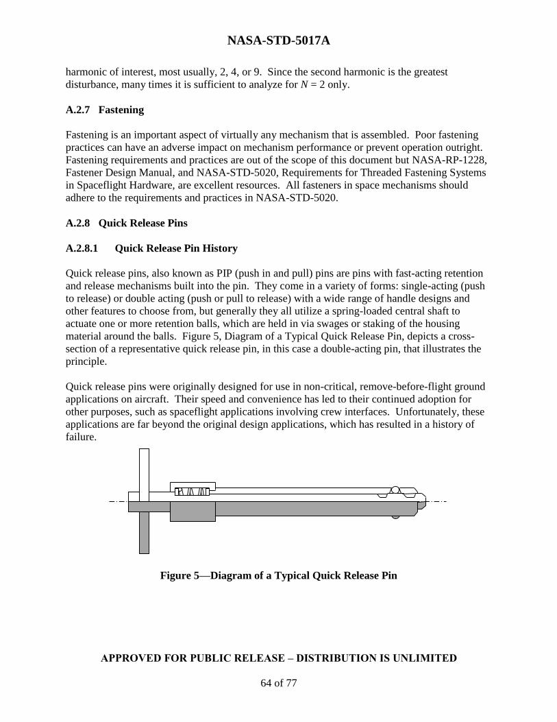
NASA-STD-5017A
APPROVED FOR PUBLIC RELEASE – DISTRIBUTION IS UNLIMITED
64 of 77
harmonic of interest, most usually, 2, 4, or 9. Since the second harmonic is the greatest
disturbance, many times it is sufficient to analyze for N = 2 only.
A.2.7 Fastening
Fastening is an important aspect of virtually any mechanism that is assembled. Poor fastening
practices can have an adverse impact on mechanism performance or prevent operation outright.
Fastening requirements and practices are out of the scope of this document but NASA-RP-1228,
Fastener Design Manual, and NASA-STD-5020, Requirements for Threaded Fastening Systems
in Spaceflight Hardware, are excellent resources. All fasteners in space mechanisms should
adhere to the requirements and practices in NASA-STD-5020.
A.2.8 Quick Release Pins
A.2.8.1 Quick Release Pin History
Quick release pins, also known as PIP (push in and pull) pins are pins with fast-acting retention
and release mechanisms built into the pin. They come in a variety of forms: single-acting (push
to release) or double acting (push or pull to release) with a wide range of handle designs and
other features to choose from, but generally they all utilize a spring-loaded central shaft to
actuate one or more retention balls, which are held in via swages or staking of the housing
material around the balls. Figure 5, Diagram of a Typical Quick Release Pin, depicts a cross-
section of a representative quick release pin, in this case a double-acting pin, that illustrates the
principle.
Quick release pins were originally designed for use in non-critical, remove-before-flight ground
applications on aircraft. Their speed and convenience has led to their continued adoption for
other purposes, such as spaceflight applications involving crew interfaces. Unfortunately, these
applications are far beyond the original design applications, which has resulted in a history of
failure.
Figure 5—Diagram of a Typical Quick Release Pin

NASA-STD-5017A
APPROVED FOR PUBLIC RELEASE – DISTRIBUTION IS UNLIMITED
65 of 77
A.2.8.2 Quick Release Pin Failures in the Space Program
Though several documented inadvertent releases of quick release pins were noted, no serious
documented failures occurred in the space program until 1990. In that year, NASA began
environmental testing of the extravehicular activity (EVA) Development Flight Experiments
payload, which contained quick release pins. During vibration testing, several locking balls in
the pins vibrated out of their sockets, and during cold temperature vacuum testing the lubricant in
the pins froze and seized the pins. NASA solved these problems by using military standard pins
that were quality controlled and removing all lubrication from the pins based on their single
mission use and because the lubrication was mainly provided for corrosion protection in the first
place.
After this failure, several design changes were proposed for quick release pins to create a more
reliable pin for space use:
Use of four retention balls instead of two to improve retention in the event of a
single ball release.
Double-action.
PTFE-coated tethers.
Welded handles and tether rings.
Addition of dry film lubricants.
Addition of hitch pin.
More detail is provided in PIP Pin Reliability and Design (Skyles, 1994).
The addition of hitch pins, which are self-retained shear pins that are placed through both the
interior shaft and exterior housing to prevent inadvertent actuation of the pin and act as a
secondary means of retention in the event of ball release, would turn out to be controversial.
Hitch pins proved to be difficult to install with gloved hands and presented snag hazards during
EVAs. Several instances of inadvertently pulled hitch pins were encountered on Hubble Space
Telescope (HST) servicing missions 3A and 3B.
In 1994, these and other problems prompted the Space Shuttle Safety Review Panel to establish a
policy in which quick release pins had to be treated as mechanisms in their own right, requiring
the same engineering rigor and review practices as other mechanisms. A continuing history of
problems led to the revision of the policy that prohibited quick release pins from being used in
zero-fault-tolerant applications in 2000.
In 2001, a set of pins that had incorporated these improvements exhibited some other problems
during preparation for HST servicing mission 3B. Pins with a two-piece welded spindle/button
construction were found to be prone to fracture. Such pins that were used only in contingency
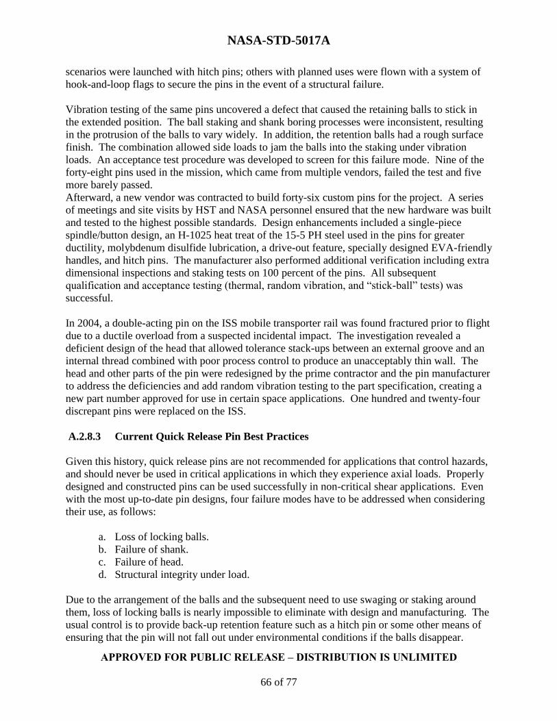
NASA-STD-5017A
APPROVED FOR PUBLIC RELEASE – DISTRIBUTION IS UNLIMITED
66 of 77
scenarios were launched with hitch pins; others with planned uses were flown with a system of
hook-and-loop flags to secure the pins in the event of a structural failure.
Vibration testing of the same pins uncovered a defect that caused the retaining balls to stick in
the extended position. The ball staking and shank boring processes were inconsistent, resulting
in the protrusion of the balls to vary widely. In addition, the retention balls had a rough surface
finish. The combination allowed side loads to jam the balls into the staking under vibration
loads. An acceptance test procedure was developed to screen for this failure mode. Nine of the
forty-eight pins used in the mission, which came from multiple vendors, failed the test and five
more barely passed.
Afterward, a new vendor was contracted to build forty-six custom pins for the project. A series
of meetings and site visits by HST and NASA personnel ensured that the new hardware was built
and tested to the highest possible standards. Design enhancements included a single-piece
spindle/button design, an H-1025 heat treat of the 15-5 PH steel used in the pins for greater
ductility, molybdenum disulfide lubrication, a drive-out feature, specially designed EVA-friendly
handles, and hitch pins. The manufacturer also performed additional verification including extra
dimensional inspections and staking tests on 100 percent of the pins. All subsequent
qualification and acceptance testing (thermal, random vibration, and “stick-ball” tests) was
successful.
In 2004, a double-acting pin on the ISS mobile transporter rail was found fractured prior to flight
due to a ductile overload from a suspected incidental impact. The investigation revealed a
deficient design of the head that allowed tolerance stack-ups between an external groove and an
internal thread combined with poor process control to produce an unacceptably thin wall. The
head and other parts of the pin were redesigned by the prime contractor and the pin manufacturer
to address the deficiencies and add random vibration testing to the part specification, creating a
new part number approved for use in certain space applications. One hundred and twenty-four
discrepant pins were replaced on the ISS.
A.2.8.3 Current Quick Release Pin Best Practices
Given this history, quick release pins are not recommended for applications that control hazards,
and should never be used in critical applications in which they experience axial loads. Properly
designed and constructed pins can be used successfully in non-critical shear applications. Even
with the most up-to-date pin designs, four failure modes have to be addressed when considering
their use, as follows:
a. Loss of locking balls.
b. Failure of shank.
c. Failure of head.
d. Structural integrity under load.
Due to the arrangement of the balls and the subsequent need to use swaging or staking around
them, loss of locking balls is nearly impossible to eliminate with design and manufacturing. The
usual control is to provide back-up retention feature such as a hitch pin or some other means of
ensuring that the pin will not fall out under environmental conditions if the balls disappear.

NASA-STD-5017A
APPROVED FOR PUBLIC RELEASE – DISTRIBUTION IS UNLIMITED
67 of 77
Failures of the shank and head can be eliminated but depend on the pin vendors since they rely
on design practices and process controls. A continuing risk is that pin manufacturers can change
their internal designs at any time without notification, so the detailed design of the mechanism
and the change history should be investigated thoroughly prior to the use of any pin. Lastly,
quick release pin structural integrity in a particular application has to be assessed; due to the
internal features of the pin, dependable allowables are not always available, are dependent upon
application, and will not cover situations such as inadvertent contact loads.
A.2.9 Inspection
Inspection of both constituent parts and assembled mechanisms is an important part of the testing
and preparation of flight mechanisms. Some materials used are more susceptible to material
defects than others and parts made from these materials should be carefully inspected prior to
acceptance. These materials include castings, fiber composites, laminates, and honeycombs.
Regardless of material, any part that represents a single-point failure should be inspected for
defects. This is often mandated by fracture control requirements if fracture control is utilized.
Careful examination should also be made of any parts that will be highly stressed.
Springs, due to their mass-produced nature, are frequently affected by initial flaws. Improper
heat treating is a common cause; for this reason, springs should have their heat treat tested on an
unstressed location whenever feasible. In cases where this can’t be done, heat treat evaluation
via lot sampling may be useful.
Inspection of assemblies should be performed both before and after to environmental,
performance, and life tests, prior to installation, and to the extent practical, after installation into
test hardware or the flight vehicle. For most aerospace mechanisms, virtually every aspect of the
mechanism can be critical in some way, and the appropriate inspections will vary widely
depending on the application. Many inspections can be mandated via drawing requirement.
Some recommended inspections are listed below.
Cleanliness.
Handling damage.
Corrosion.
Critical clearances and dimensions (especially of wire harnesses and multilayer
insulation).
Proper thread engagement.
Proper fastener torque/preload (where relaxation is not a concern or is accounted for,
this can be accomplished easily with verification during assembly coupled with
torque striping—a technique that seems to be underemployed).
Proper installation of lock wire or safety cable.

NASA-STD-5017A
APPROVED FOR PUBLIC RELEASE – DISTRIBUTION IS UNLIMITED
68 of 77
Condition of electrical and fluid connectors.
Wiring harness retention.
Spring integrity.
Leakage of fluid-filled components.
Excessive wear.
Lubricant condition and availability.
Evidence of unintentional contact between parts.
Generated debris.
The method of inspection will vary depending on what is being inspected, the effect of the
inspection on the parts inspected, and access to the parts. Non-destructive techniques include
visual inspections, visualization under magnification (optical or scanning electron microscopy),
X-ray, N-ray, eddy current inspection, magnetic particle inspection, dye penetrant inspection.
Destructive techniques such as sectioning are not often used, being reserved mainly for
development activities or failure investigations.
Photographs of the parts and assemblies should generally be taken any time any type of
inspection is performed, even if limited to quick visual scans, in order to document the condition
of the unit. Verification that photographs exist of each part showing all surfaces should be made
prior to the installation of that part into the next level of assembly. Photographs should also be
taken of the assembly from all angles necessary to indicate its condition prior to installation into
test equipment and after installation into test equipment. Special attention should be paid to
surfaces and components that are expected to deflect, wear, or have the possibility of moving
during the test. All externally visible screws should be photographed with enough detail to be
able to see a change in orientation, if not torque-striped. The same set of photographs should be
taken before and after any change in configuration.
A.2.10 Qualification Testing
Qualification testing is conducted to verify that mechanism’s design, materials, and
manufacturing processes meet specification requirements. Qualification testing includes tests that
verify hardware functions during and after exposure to the specified environments. The testing
typically stresses the hardware beyond the design conditions to ensure that margins exist. The
margins applied during qualification are typically program-specified.
All mechanisms are required to undergo qualification testing, and this should be done at the
mechanism level of assembly whenever possible. At the project's discretion, however, such
testing may be performed at higher levels of assembly, after any other testing that may affect
mechanical operation in order to confirm proper performance and to ensure that no degradation
NASA-STD-5017A
APPROVED FOR PUBLIC RELEASE – DISTRIBUTION IS UNLIMITED
69 of 77
has occurred during the previous tests. All functions of the mechanism have to be included in
qualification testing, including redundant modes of operation.
Qualification testing should utilize hardware that is as flight-like as possible, including any drive
electronics and controllers. Qualification tests should use the same test hardware that is expected
to be used in acceptance testing. This includes any resident firmware and software, test
fixturing, test facilities, and test support equipment.
The qualification test should assess design requirements levied in the mechanism’s specification.
The specification should include all worst-case service environments and operational cycles for
the applicable item’s service life, which includes acceptance tests (including acceptance
retesting), tests at higher levels of assembly, mission operations, and ground operations.
Qualification tests should be performed for each mechanical operation at nominal-, low-, and
high-energy levels. To establish that functioning is proper for normal operations, the nominal test
should be conducted under the most probable conditions expected during normal flight. A high-
energy test and a low-energy test should also be conducted to prove positive margins of strength
and function. Adverse interaction of potential extremes of parameters such as temperature,
friction, spring forces, stiffness of electrical cabling or thermal insulation, and spin rate should be
addressed. Parameters to be varied during the high and low-energy tests should include all those
that could substantively affect the operation of the mechanism as determined by the results of
analytic predictions or development tests. Worst-case torque or force margins should be
determined by simulating the lowest motive force combined with the highest resistance under the
most adverse environmental conditions.
The types of environmental qualification testing required for mechanisms are typically
established by the program, but a recommended set of tests is given in table 4, Recommended
Environmental Qualification Test Matrix for Mechanisms. Design life testing is not included in
this list because it is treated separately from other qualification tests in this document.
Mechanisms that include unique types of components may require other types of tests in addition
to these. The recommended test sequence is listed in table 5, Recommended Testing Sequence;
however, there is no single correct order to ensure maximum effectiveness applicable to all
mechanisms. The order of testing is most valid if it is in agreement with the order in which the
environments will be encountered by the flight hardware during its mission life.
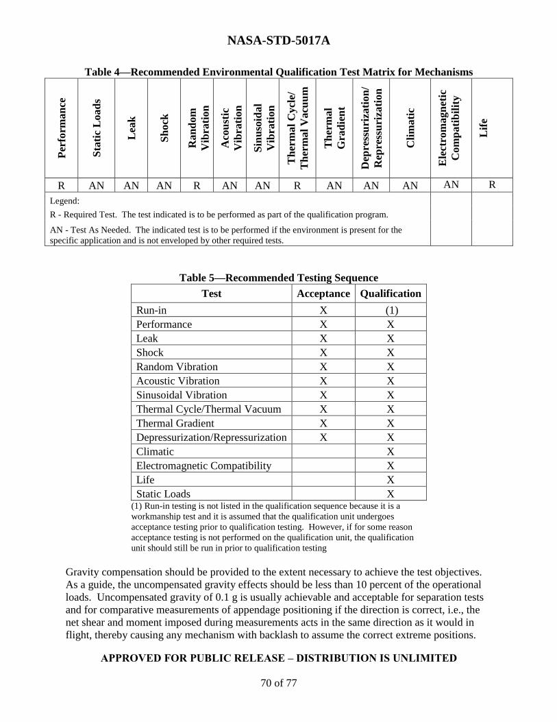
NASA-STD-5017A
APPROVED FOR PUBLIC RELEASE – DISTRIBUTION IS UNLIMITED
70 of 77
Table 4—Recommended Environmental Qualification Test Matrix for Mechanisms P
erfo
rman
ce
Sta
tic
Load
s
Lea
k
Sh
ock
Ran
dom
Vib
rati
on
Aco
ust
ic
Vib
rati
on
Sin
uso
idal
Vib
rati
on
Th
erm
al
Cycl
e/
Th
erm
al
Vacu
um
Th
erm
al
Gra
die
nt
Dep
ress
uri
zati
on
/
Rep
ress
uri
zati
on
Cli
mati
c
Ele
ctro
magn
eti
c
Com
pati
bil
ity
Lif
e
R AN AN AN R AN AN R AN AN AN AN R
Legend:
R - Required Test. The test indicated is to be performed as part of the qualification program.
AN - Test As Needed. The indicated test is to be performed if the environment is present for the
specific application and is not enveloped by other required tests.
Table 5—Recommended Testing Sequence
Test Acceptance Qualification
Run-in X (1)
Performance X X
Leak X X
Shock X X
Random Vibration X X
Acoustic Vibration X X
Sinusoidal Vibration X X
Thermal Cycle/Thermal Vacuum X X
Thermal Gradient X X
Depressurization/Repressurization X X
Climatic X
Electromagnetic Compatibility X
Life X
Static Loads X (1) Run-in testing is not listed in the qualification sequence because it is a
workmanship test and it is assumed that the qualification unit undergoes
acceptance testing prior to qualification testing. However, if for some reason
acceptance testing is not performed on the qualification unit, the qualification
unit should still be run in prior to qualification testing
Gravity compensation should be provided to the extent necessary to achieve the test objectives.
As a guide, the uncompensated gravity effects should be less than 10 percent of the operational
loads. Uncompensated gravity of 0.1 g is usually achievable and acceptable for separation tests
and for comparative measurements of appendage positioning if the direction is correct, i.e., the
net shear and moment imposed during measurements acts in the same direction as it would in
flight, thereby causing any mechanism with backlash to assume the correct extreme positions.

NASA-STD-5017A
APPROVED FOR PUBLIC RELEASE – DISTRIBUTION IS UNLIMITED
71 of 77
For testing of certain mechanical functions, however, more stringent uncompensated gravity
constraints may be required.
In order to reduce the risk of workmanship-related failures during the qualification test program,
it is recommended that an acceptance test be performed on the qualification hardware prior to
beginning the qualification test program.
A.2.10.1 Design Life Testing
Mechanisms often experience a wide range of environments in service and the temperature at
which the mechanism will perform any given cycle is usually not precisely known, so adequately
representing the entire range in design life testing can be a challenge. A common approach is to
conduct 50 percent of the cycles at nominal expected operating conditions (which are not
necessarily room-temperature conditions), 25 percent at the maximum expected operating
temperature, and 25 percent at the minimum expected operating temperature. If the make-up of
the cycle temperatures in service is more accurately known, the split during the design life test
should reflect that. The pressure during operational cycles is usually much better understood, so
if the hardware will experience vacuum or reduced atmospheric pressure during a portion of its
design life and the mechanism contains vacuum-sensitive components, a representative fraction
of the total cycles should be performed in the appropriate pressure conditions. Vacuum-sensitive
components typically include lubricants and material combinations susceptible to cold welding.
The order in which the environments are applied in the test should follow the order that the
mechanism will experience the environments in service as closely as possible.
It is important to accurately represent the demands on a mechanism during the life test, including
driven inertias. In some cases, it may be more appropriate to substitute a dummy load for the
actual driven member so long as the dummy load provides a reasonable representation of the
dynamic characteristics of the actual driven hardware (such as inertia, stiffness, free play, and
natural frequencies).
There is often a desire to replace integrated, mechanism-level life testing with component-level
life testing for schedule and cost purposes among others. While component life can provide
valuable information, it does not take the place of integrated testing. Interactions between
components often create conditions that cannot be replicated or even anticipated in component-
level tests.
Design life tests for long-term missions often require accelerated testing. This needs to be
approached carefully with knowledge of the failure modes of the hardware and potential
undesirable consequences of increased speed. For example, changing the rotational speed of a
bearing may change the lubrication regime in which the bearing operates. For boundary and
mixed lubrication regimes, the most likely failure mechanisms will be wear and lubricant
breakdown, not fatigue. A bearing that normally operates in a boundary lubrication or mixed
lubrication regime should never be accelerated to a level where the bearing operates in the EHD
lubrication regime during the test. In the EHD regime, no appreciable wear should occur and the
failure mechanism should be material fatigue rather than wear. Therefore, while life test
acceleration by increasing speed may be considered, other speed-limiting factors need also be
NASA-STD-5017A
APPROVED FOR PUBLIC RELEASE – DISTRIBUTION IS UNLIMITED
72 of 77
considered. For example, at the speed at which EHD lubrication is attained, one has to evaluate
bearing retainer instability which may produce excessive wear of the retainer and would in turn
produce contaminants that could degrade the performance of the bearings. Additionally, thermal
issues may arise related to increased power dissipation for higher speed operation, like increased
bearing gradients, which should be thoroughly evaluated. Even performing the test at flight
speeds can mask failure modes when the quiescent durations are not included in the life test—
continuous cycling can prevent cold welding that would otherwise manifest itself during
expected periods of inactivity. For all these reasons, the life test should be run as nearly as
possible using the on-orbit speeds and duty cycles. In some cases it may not be possible to
accelerate the test at all. One should be careful not to perform a test that is unrepresentative of
the design conditions.
Certain dry-film lubricants, particularly molybdenum disulfide-based lubricants, perform better
and degrade less quickly in a vacuum than they do in an atmospheric environment. For this
reason, life verification tests performed in atmospheric conditions may be conservative in this
respect, but by the same token this increase in lubricity can have undesirable effects such as
changes in achieved preload of EVA bolts. Conversely, the increased friction in ambient
pressure can accelerate wear and generate debris. All effects of a vacuum on the mechanism in
question need to be considered when selecting the life test environment.
As stated in the rationale for inspections of design life test hardware, a thorough inspection of the
life test unit is necessary in order to assess the hardware for anomalous conditions or indications
of failure. Such inspections may include physical dimensional inspection of components, high
magnification photography, lubricant analysis, scanning electron microscope analysis, or other
techniques. Photographic documentation of the life test article should be made from component
inspection and acceptance through full assembly to act as a baseline for comparison. The critical
areas of parts that may be subject to fatigue failure should be inspected to determine whether
failure has occurred. Where lubrication is used, it may be prudent to measure lubricant loss,
degradation, distribution, and condensed outgassed constituents.
When determining the calculated number of life cycles, it is important to consider the number of
cycles at component assembly, performance baseline testing, cycles expended during and after
exposure to environments (e.g., thermal-vacuum and random vibration) as well as those cycles
needed at higher levels of assembly to demonstrate the performance of the entire instrument or
flight system (e.g., system calibrations or comprehensive performance tests), up to and including
launch site operations if applicable. It is often advisable to add some margin to the calculated
number of life cycles to allow for anomaly investigations or other unforeseen needs. This
margin allows for the mechanism to be functioned during investigation without using up flight
cycle life and exceeding the life certification. This margin is added before applying any test
factors.
Mechanisms often have reliability requirements assigned to them, and sometimes there is
confusion regarding whether the reliability number should be applied to the expected life before
or after the life test factor is applied. Unless otherwise specified, the reliability should be applied
to the expected life before the life test factor is applied.
NASA-STD-5017A
APPROVED FOR PUBLIC RELEASE – DISTRIBUTION IS UNLIMITED
73 of 77
The life test factor utilized in this document is a result of the aerospace industry's common
practice of building only one life test unit. If only one unit is tested, and it is tested only to the
number of cycles it is expected to see, there is no information available to establish confidence
that another unit will last as long. To account for this unit-to-unit variation, a factor has to be
added to the number of cycles in the test to demonstrate a degree of robustness in the design.
Another possible approach, especially in applications where life requirements approach the state
of the art, is to build multiple life test units and test them to a reduced factor. There is no
standardized methodology for this approach, so the reduced factors and the number of life test
units have to be assessed on a case-by-case basis to determine an acceptable plan.
A.2.11 Acceptance Testing
Acceptance testing is used to verify that the manufacturing and assembly process has been
accomplished in an acceptable manner and that the as-built unit performs within specified
parameters. Acceptance testing includes integrity tests that verify hardware functions during and
after exposure to the specified environments (e.g., performance tests).
The types of acceptance testing required for mechanisms are typically established by the
program, but a recommended set of tests is given in table 6, Recommended Environmental
Acceptance Test Matrix for Mechanisms. Run-in is not included in this list because it is treated
separately from other acceptance tests in this document but note that as required in section 4, the
run-in test is to be performed prior to all other acceptance testing. Mechanisms that include
unique types of components may require other types of tests in addition to these. The
recommended test sequence is listed in table 5; however, there is no single correct order to
ensure maximum effectiveness applicable to all mechanisms. The order of testing is most valid
if it is in agreement with the order in which the environments will be encountered by the flight
hardware during its mission life.
All mechanisms have to undergo acceptance testing, and this should be done at the mechanism
level of assembly whenever possible. At the project's discretion, however, such testing may be
performed at higher levels of assembly, after any other testing that may affect mechanical
operation in order to confirm proper performance and to ensure that no degradation has occurred
during the previous tests.

NASA-STD-5017A
APPROVED FOR PUBLIC RELEASE – DISTRIBUTION IS UNLIMITED
74 of 77
Table 6—Recommended Environmental Acceptance
Test Matrix for Mechanisms
Per
form
an
ce
Lea
k
Sh
ock
Ran
dom
Vib
rati
on
Aco
ust
ic
Vib
rati
on
Sin
uso
idal
Vib
rati
on
Th
erm
al
Cycl
e/
Th
erm
al
Vacu
um
Th
erm
al
Gra
die
nt
Dep
ress
uri
zati
on
/
Rep
ress
uri
zati
on
R AN AN R AN AN R AN AN
Legend:
R - Required Test. The test indicated is to be performed as part of the qualification
program.
AN - Test As Needed. The indicated test is to be performed if the environment is present
for the specific application and is not enveloped by other required tests.
Note: Run-in is not included in this matrix because it is not an environmental test. Run-in
is performed prior to all environmental acceptance testing.
Regardless of the level of assembly of the acceptance testing, mechanical function tests should
be performed after integration into the spacecraft to demonstrate freedom-of-motion of all
appendages and other mechanical devices whose operation may be affected by the process of
integrating them with the payload. The tests have to demonstrate proper release, motion, and
lock-in of each device, as appropriate, in order to ensure that no tolerance buildup, assembly
error, or other problem will prevent proper operation of the mechanism during mission life.
Unless the design of the device dictates otherwise, mechanical testing may be conducted in
ambient laboratory conditions. The testing should be performed at an appropriate time in the
payload environmental test sequence and, if any device in the vicinity of the mechanism (or the
mechanism itself) is subsequently removed from the payload, the testing has to be repeated after
final reinstallation of the device.
All functions of the mechanism have to be included in acceptance testing, including redundant
modes of operation, with the obvious exception of single-use hardware for which no
refurbishment is possible, such as ordnance. Acceptance tests have to be structured to detect
workmanship defects that could affect operational performance.
Acceptance testing is performed on flight hardware by definition, but care should be taken to
ensure that any drive electronics and controllers are also flight units or as flight-like as possible.
The acceptance testing of mechanisms that are part of deployable or movable systems should be
conducted with the mechanism attached to the movable system whenever possible. In some
cases, it may be more appropriate to substitute a dummy load for the driven member so long as
the dummy load provides a reasonable representation of the dynamic characteristics of the actual
driven hardware (such as inertia, stiffness, free play, and natural frequencies). It is also highly
recommended to perform acceptance testing on qualification hardware.

NASA-STD-5017A
APPROVED FOR PUBLIC RELEASE – DISTRIBUTION IS UNLIMITED
75 of 77
A.2.12 Protoflight Testing
Protoflight refers to a strategy where no test-dedicated qualification article exists and all
production hardware is intended for flight. Typically, protoflight testing exposes all flight
hardware to environments at qualification magnitudes for acceptance durations. In cases where a
qualification test would generally be required without a corresponding acceptance test, the
protoflight test is the same as the qualification test. However, sometimes adjustments need to be
made to the test duration or levels to prevent unnecessary wear or consumption of life.
Adjustment of qualification test parameters to avoid such erosion of capability have to be
reviewed carefully to avoid incurring undue risk.
Because the hardware is used for flight, testing that is intended to demonstrate service life or
ultimate strength capability cannot be performed on protoflight hardware. A protoflight
approach therefore carries a higher technical risk than a full qualification test program. The
protoflight approach should thus be used with caution and used only for low-risk applications
since no design margin for fatigue, wear, or yield is demonstrated.
The risk generated by a protoflight approach should be mitigated using measures such as
increased development testing (including component-level life testing), increased component-
level qualification testing, and use of higher factors of safety.

NASA-STD-5017A
APPROVED FOR PUBLIC RELEASE – DISTRIBUTION IS UNLIMITED
76 of 77
APPENDIX B
REFERENCES
B.1 Purpose
The purpose of this appendix is to provide additional information on references mentioned in the
text of this Standard.
B.2 References
B.2.1 Government Documents
Department of Defense
Document Number Document Title
MIL-PRF-27617G
Grease, Aircraft and Instrument, Fuel and Oxidizer
Resistant, Amendment 1
MIL-PRF-46010H Lubricant, Solid Film, Heat Cured, Corrosion Inhibiting
NASA
Document Number Document Title
PD-ED-1229
Preferred Reliability Practice, Selection of Electric Motors
for Aerospace Applications
NASA-RP-1228 Fastener Design Manual
NASA-SP-38 Advanced Bearing Technology
NASA-STD-5020 Requirements for Threaded Fastening Systems in
Spaceflight Hardware
NASA-STD-6016 Standard Materials and Processes Requirements for
Spacecraft
NASA/TP-1999-206988 NASA Space Mechanisms Handbook

NASA-STD-5017A
APPROVED FOR PUBLIC RELEASE – DISTRIBUTION IS UNLIMITED
77 of 77
B.2.2 Non-Government Documents
ASTM International
Document Number Document Title
E595
Standard Test Method for Total Mass Loss and Collected
Volatile Condensable Materials from Outgassing in a
Vacuum Environment
Other Documents
Leveille, A.; Murphy, J. (1973). Determination of the Influence of Static Loads on the Output
Torque of Instrument Ball Bearings. Paper presented at the International Ball Bearing
Symposium. The Charles Stark Draper Laboratory, Inc.: Cambridge, MA.
Loewenthal, Stuart H. (1988). Two Gimbal Bearing Case Studies: Some Lessons Learned.
Proceedings of the 22nd Aerospace Mechanisms Symposium. Mechanisms Education
Association: Hampton, VA, 253-269.
Park, W. et al. (1998). Rolling Contact Fatigue and Load Capacity Tests of M62 Bearing
Steel. Proceedings of the 32nd Aerospace Mechanisms Symposium. Mechanisms
Education Association: Cocoa Beach, FL, 237-1251.
Schroeder, J. R. (2010). Demystifying the 2:1 Ratio and the Stick-Slip Phenomenon: A
Technical Whitepaper Explaining the Theory Behind the Binding Ratio and How It
Relates to Stick-Slip. PBC Linear, a division of Pacific Bearing Company: Rockford, IL.
Sevilla, D. (2010). Brush Motors and Brushless Motors - Flight System Design
Considerations. White Paper, Jet Propulsion Laboratory: Pasadena, CA.
Skyles, Lane P. (1994). PIP Pin Reliability and Design. Proceedings of the 28th Aerospace
Mechanisms Symposium. Mechanisms Education Association:
Cleveland, OH, 153-158.
Recommended