H14531.2
Technical White Paper
Dell EMC PowerMax: iSCSI Implementation for Dell EMC Storage Arrays Running PowerMaxOS
Abstract This document provides an in-depth overview of the Dell EMC™ PowerMaxOS iSCSI implementation on Dell EMC PowerMax and VMAX™ All Flash storage arrays.
September 2019

Revisions
2 Dell EMC PowerMax: iSCSI Implementation for Dell EMC Storage Arrays Running PowerMaxOS | H14531.2
Revisions
Date Description
October 2016 Initial release
April 2018 Updated for PowerMaxOS
September 2019 Updated for PowerMaxOS Q319 SR
Acknowledgements Author: James Salvadore
The information in this publication is provided “as is.” Dell Inc. makes no representations or warranties of any kind with respect to the information in this publication, and specifically disclaims implied warranties of merchantability or fitness for a particular purpose. Use, copying, and distribution of any software described in this publication requires an applicable software license. Copyright © 2016-2019 Dell Inc. or its subsidiaries. All Rights Reserved. Dell, EMC, Dell EMC and other trademarks are trademarks of Dell Inc. or its subsidiaries. Other trademarks may be trademarks of their respective owners. [9/10/2019] [Technical White Paper] [H14531.2]

Table of contents
3 Dell EMC PowerMax: iSCSI Implementation for Dell EMC Storage Arrays Running PowerMaxOS | H14531.2
Table of contents Revisions............................................................................................................................................................................. 2
Acknowledgements ............................................................................................................................................................. 2
Table of contents ................................................................................................................................................................ 3
Executive summary ............................................................................................................................................................. 4
Audience ............................................................................................................................................................................. 4
1 iSCSI overview ............................................................................................................................................................. 5
1.1 Key iSCSI concepts and terminology ................................................................................................................. 5
1.2 Primary benefits of iSCSI ................................................................................................................................... 8
1.3 Core components of iSCSI ................................................................................................................................. 8
1.3.1 Initiators and target nodes .................................................................................................................................. 8
1.3.2 Names ................................................................................................................................................................ 9
1.3.3 IP interfaces ........................................................................................................................................................ 9
1.3.4 Sessions and connections .................................................................................................................................. 9
1.3.5 Security and authentication .............................................................................................................................. 10
1.4 How iSCSI works .............................................................................................................................................. 11
1.4.1 The login process ............................................................................................................................................. 11
1.4.2 The data transfer process ................................................................................................................................. 11
1.5 How iSCSI compares with other storage transport protocols ........................................................................... 13
1.6 Deployment considerations for iSCSI ............................................................................................................... 17
1.6.1 Network Considerations ................................................................................................................................... 17
1.6.2 Multipathing and availability considerations ..................................................................................................... 17
1.6.3 Resource consumption considerations ............................................................................................................ 18
2 PowerMaxOS iSCSI implementation overview .......................................................................................................... 20
2.1 Background ....................................................................................................................................................... 20
2.2 The PowerMaxOS iSCSI implementation design objectives ............................................................................ 20
2.3 PowerMaxOS iSCSI implementation core components ................................................................................... 21
2.3.1 Hardware: Quad Port 10GbE Interface Module ............................................................................................... 21
2.3.2 PowerMaxOS iSCSI target node ...................................................................................................................... 21
2.3.3 PowerMaxOS iSCSI IP interface ...................................................................................................................... 24
2.3.4 CHAP authentication ........................................................................................................................................ 25
2.3.5 Routing instance ............................................................................................................................................... 30
2.4 PowerMaxOS iSCSI host connectivity limits .................................................................................................... 32
3 Summary .................................................................................................................................................................... 34
A Technical support and resources ............................................................................................................................... 35
A.1 Related resources............................................................................................................................................. 35

Executive summary
4 Dell EMC PowerMax: iSCSI Implementation for Dell EMC Storage Arrays Running PowerMaxOS | H14531.2
Executive summary Dell EMC offers Internet Small Computer Serial Interface (iSCSI) connectivity to our existing and new customers which provides a potentially lower-cost alternative connectivity method between hosts/virtual machines to Dell EMC™ PowerMaxOS-based storage arrays. At a high-level, the primary benefits of the iSCSI storage protocol are as follows:
• Makes consolidated storage possible for a wide range of businesses. • Enables cost-effective, scalable, secure, and highly-available storage area networks (SANs). • Leverages existing management skills and network infrastructure. • Delivers performance comparable to Fibre Channel. • Provides interoperability using industry standards.
The PowerMaxOS iSCSI solution has been built from the ground up to take advantage of virtual local area networks (VLANs) to provide customers with greater host/port/connection densities which also provides built in multi-tenancy capabilities as the front end ports can be virtualized and partitioned. This design makes the PowerMaxOS iSCSI solutionan ideal connectivity choice when considering lower cost storage options for converged infrastructures and all virtualized environments.
Audience This document is intended for Dell EMC field personnel, including technology consultants, and for customer storage architects, administrators, and operators involved in managing, operating, or designing a storage infrastructure which contains PowerMaxOS-based storage arrays.

iSCSI overview
5 Dell EMC PowerMax: iSCSI Implementation for Dell EMC Storage Arrays Running PowerMaxOS | H14531.2
1 iSCSI overview iSCSI is a transport layer protocol that uses the Transmission Control Protocol/Internet Protocol (TCP/IP) to transport SCSI packets, enabling the use of Ethernet based networking infrastructure as a storage area network (SAN). Like Fibre Channel and other storage transport protocols, iSCSI transports block level data between an initiator on a server and a target on a storage device. IBM developed iSCSI as a proof of concept in 1998 and was ratified as a transport protocol by the Internet Engineering Task Force (IETF) in 2003. The current iSCSI standard is IETF RFC 7143 and can be found at https://tools.ietf.org/html/rfc7143.
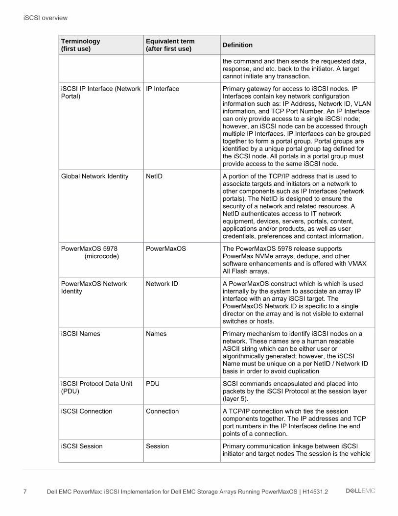
1.1 Key iSCSI concepts and terminology This white paper will consistently use / make reference to specific concepts and terminology. The following table provides a detailed list of these terms and their definitions:
Key iSCSI technologies and terminology Terminology (first use)
Equivalent term (after first use)
Definition
Open Systems Interconnection Model
OSI model A seven layer conceptual model that characterizes and standardizes the communication functions of a telecommunication or computer network system without regard to its underlying internal structure and technology. The primary layers are the application (layer 7), Presentation (layer 6), Session (layer 5), Transport (layer 4), Network (layer 3), Datalink (layer 2), Physical (Layer 1)
Ethernet Ethernet A family of computer networking technologies operating at the OSI physical layer (layer 1) also providing services to the OSI datalink layer (layer 2). Ethernet is commonly used in local area networks (LAN) and wide area networks (WAN). Systems communicating over Ethernet based networks divide a stream of data into frames. Each frame contains source and destination addresses, and error-checking data so that damaged frames can be detected, discarded, and retransmitted when needed. Ethernet can use physical mediums of twisted pair and fiber optic links which currently are capable of reaching speeds of 10 Gbps (10 GbE), 25 Gbps, 40 Gbps, 50 Gbps, and now 100 Gbps.
Virtual Local Area Network (VLAN)
VLAN Any broadcast domain that is partitioned and isolated in computer network at the datalink layer (layer 2). VLANs work by applying tags to network packets and handling these tags in networking systems – creating the appearance and functionality of network traffic that is physically on a single network but acts as if it is split between separate networks.
Transmission Control Protocol / Internet Protocol
TCP/IP A suite of communication protocols used to interconnect devices on communication networks. TCP/IP specifies how data can be exchanged over networks. TCP specifically defines how applications can create channels of communication across a

iSCSI overview
6 Dell EMC PowerMax: iSCSI Implementation for Dell EMC Storage Arrays Running PowerMaxOS | H14531.2
Terminology (first use)
Equivalent term (after first use)
Definition
network. It manages how data is assembled into smaller packets before it is transmitted over the network and how it is to be reassembled at the destination address. In the OSI model, TCP provides services to the transport layer (layer 4) and some services to the session layer (layer 5). IP specifically defines how to address and route each packet to make sure it reaches the correct destination on the network. In the OSI model, IP provides services to the network layer (layer 3).
Small Computer System Interface (SCSI)
SCSI A set of standards for physically connecting and transferring data between computers and peripheral devices such as disk storage. The SCSI standards define commands, protocols, and electrical and optical interfaces.
Storage Area Network SAN A specialized, high-speed network that provides block-level network access to storage. A SAN consists of two types of equipment: initiator and target nodes. Initiators, such as hosts, are data consumers. Targets, such as disk arrays or tape libraries, are data providers. A SAN presents storage devices to a host such that the storage appears locally attached. SAN initiators and targets can be interconnected using a variety of technologies, topologies, and transport layer protocols.
Internet Small Computer Serial Interface (iSCSI)
iSCSI A transport layer protocol that uses TCP/IP to transport SCSI commands enabling Ethernet based networks to function as a storage area network (SAN). iSCSI uses TCP/IP to move block data between iSCSI initiators nodes and iSCSI target nodes
iSCSI Initiator Node Initiator Host based hardware (virtual or physical) or software which sends data to and from iSCSI target nodes (storage arrays). The initiator is the one who requests for the data to be read from or written to the storage. In case of read operation, initiator sends a SCSI READ command to the peer who acts as a target and in return the target sends the requested data back to the initiator. In case of a write operation, initiator sends a SCSI WRITE command followed by the data packets to the target. The initiator always initiates the transactions.
iSCSI Target Node Target Storage arrays, tape drives, storage servers on a SAN. In iSCSI, targets can be associated with either virtual or physical entities. A storage array target exposes one or more SCSI LUNs to specific initiators. A target is the one who processes the SCSI commands from the initiator. Upon receiving the command from the initiator, the target executes
iSCSI overview
7 Dell EMC PowerMax: iSCSI Implementation for Dell EMC Storage Arrays Running PowerMaxOS | H14531.2
Terminology (first use)
Equivalent term (after first use)
Definition
the command and then sends the requested data, response, and etc. back to the initiator. A target cannot initiate any transaction.
iSCSI IP Interface (Network Portal)
IP Interface Primary gateway for access to iSCSI nodes. IP Interfaces contain key network configuration information such as: IP Address, Network ID, VLAN information, and TCP Port Number. An IP Interface can only provide access to a single iSCSI node; however, an iSCSI node can be accessed through multiple IP Interfaces. IP Interfaces can be grouped together to form a portal group. Portal groups are identified by a unique portal group tag defined for the iSCSI node. All portals in a portal group must provide access to the same iSCSI node.
Global Network Identity
NetID A portion of the TCP/IP address that is used to associate targets and initiators on a network to other components such as IP Interfaces (network portals). The NetID is designed to ensure the security of a network and related resources. A NetID authenticates access to IT network equipment, devices, servers, portals, content, applications and/or products, as well as user credentials, preferences and contact information.
PowerMaxOS 5978 (microcode)
PowerMaxOS The PowerMaxOS 5978 release supports PowerMax NVMe arrays, dedupe, and other software enhancements and is offered with VMAX All Flash arrays.
PowerMaxOS Network Identity
Network ID A PowerMaxOS construct which is which is used internally by the system to associate an array IP interface with an array iSCSI target. The PowerMaxOS Network ID is specific to a single director on the array and is not visible to external switches or hosts.
iSCSI Names Names Primary mechanism to identify iSCSI nodes on a network. These names are a human readable ASCII string which can be either user or algorithmically generated; however, the iSCSI Name must be unique on a per NetID / Network ID basis in order to avoid duplication
iSCSI Protocol Data Unit (PDU)
PDU SCSI commands encapsulated and placed into packets by the iSCSI Protocol at the session layer (layer 5).
iSCSI Connection Connection A TCP/IP connection which ties the session components together. The IP addresses and TCP port numbers in the IP Interfaces define the end points of a connection.
iSCSI Session Session Primary communication linkage between iSCSI initiator and target nodes The session is the vehicle
iSCSI overview
8 Dell EMC PowerMax: iSCSI Implementation for Dell EMC Storage Arrays Running PowerMaxOS | H14531.2
Terminology (first use)
Equivalent term (after first use)
Definition
for the transport of the iSCSI PDUs between the initiators and target nodes.
Challenge Handshake Authentication Protocol (CHAP)
CHAP The most commonly used iSCSI authentication method. CHAP verifies identity using a hashed transmission of a secret key between initiator and target.
1.2 Primary benefits of iSCSI With the proliferation of 10GbE networking in the last few years, iSCSI has steadily gained footprint as a deployed storage protocol in datacenters. For data centers with centralized storage, iSCSI offers customers many benefits. Developed by the Internet Engineering Task Force (IETF) as a response to the need for interoperability in networked storage, iSCSI lets businesses create TCP/IP based SANs that deliver the performance comparable to Fibre Channel, but at a lower cost.
The iSCSI protocol can achieve lower costs because the protocol allows for the encapsulation of SCSI commands on a standard TCP/IP connection and transported over an Ethernet based network. This means that host standard Ethernet network interface cards (NICs) and network switches can be used to carry storage traffic, eliminating the need for a more expensive specialized storage network using separate switches and host bus adapters (HBAs). Using fewer deployed ports means fewer deployed switches which can result in lower infrastructure, administration, power consumption, and cooling costs. Cost reduction and consolidation of equipment are primary drivers behind the push to converged infrastructures; hence why iSCSI is a highly considered storage protocol for customers looking to go converged.
Another benefit that iSCSI has by using the Ethernet protocol is that the iSCSI protocol does not need change as Ethernet speeds increase from 10 GbE to 25GbE, and beyond. This is not the case with other storage transport protocols such as Fibre Channel, which need to define the entire protocol stack from the physical signaling level to all of the network switching, reliability, and packet ordering. These interdependencies slow the development of the protocol, evident as how Ethernet has surpassed Fibre Channel with supported network speeds available to the industry (i.e. Fibre Channel currently supports 32 Gbps while Ethernet supports up to 100 Gbps).
1.3 Core components of iSCSI iSCSI architecture is made up of a set of core components. These components are initiator and target nodes, iSCSI names, IP Interfaces, sessions and connections, and security.
1.3.1 Initiators and target nodes A storage area network (SAN) consists of two types of equipment: initiator and target nodes. Initiators, such as hosts, are data consumers. Targets, such as disk arrays or tape libraries, are data providers. iSCSI based SANs use initiators and targets in the same manner.
• iSCSI initiator nodes are typically host based software or hardware which sends data to and from iSCSI target nodes (storage arrays). In data migration between storage arrays, the source array can act as an initiator.

iSCSI overview
9 Dell EMC PowerMax: iSCSI Implementation for Dell EMC Storage Arrays Running PowerMaxOS | H14531.2
• iSCSI target nodes expose one or more SCSI LUNs to specific iSCSI initiators. On the enterprise storage level, iSCSI target nodes are logical entities, not tied to a specific physical port.
iSCSI initiators must manage multiple, parallel communication links to multiple targets. Similarly, iSCSI targets must manage multiple, parallel communication links to multiple initiators. Several identifiers exist in the iSCSI protocol to make this happen, including iSCSI Name, ISID (iSCSI session identifiers), TSID (target session identifier), CID (iSCSI connection identifier) and iSCSI portals.
1.3.2 Names iSCSI nodes are identified by a unique iSCSI Name. iSCSI names are a human readable ASCII string and must be unique on a per NetID / Network ID basis. iSCSI names can be both user and algorithmically generated. iSCSI Names are formatted in two different ways:
• Enterprise Unique Identifier (EUI): eui.0123456789ABCDEF • iSCSI Qualified Name (IQN) - most commonly used naming format: iqn.2001-
05.com.mircosoft:ProdHost
1.3.3 IP interfaces iSCSI Nodes are accessed through IP Interfaces (sometimes called Network Portals). iSCSI IP Interfaces contain key network configuration information such as:
• IP Address • VLAN information • TCP Port Number
An iSCSI IP Interface can only provide access to a single iSCSI node; however, an iSCSI node can be accessed through multiple IP Interfaces.
1.3.4 Sessions and connections iSCSI initiator and target nodes communicate by a linkage called an iSCSI session. The session is the vehicle for the transport of the iSCSI PDUs between the initiators and target nodes. Each session is started by the initiator logging into the iSCSI target. The session between the initiator and target is identified by an iSCSI session ID. Session IDs are not tied to the hardware and can persist across hardware swaps.
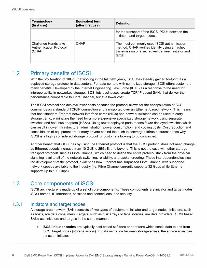
Session components are tied together by a TCP/IP connection. The IP addresses and TCP port numbers in the IP interfaces define the end points of a connection. The iSCSI protocol allows for multiple connections within a single session (MC/S) as means to provide connection resiliency to a target which is presenting volumes to the host; however, MC/S is rarely done with enterprise iSCSI connections as most enterprise implementations use host based multipath IO software (MPIO). Using host based MPIO, a single host initiator can access the same devices by presenting them through multiple targets on the storage array. This allows the host to see the devices through multiple paths. Each path from the initiator to the targets will have its own session and connection. This connectivity method is often referred to as “port binding”. The diagram below shows these iSCSI connectivity methods:
iSCSI overview
10 Dell EMC PowerMax: iSCSI Implementation for Dell EMC Storage Arrays Running PowerMaxOS | H14531.2
iSCSI connectivity methods
1.3.5 Security and authentication The most commonly used iSCSI authentication method is Challenge Handshake Authentication Protocol (CHAP). CHAP verifies identity using a hashed transmission of a secret key between initiator and target. The iSCSI specification RFC 7143 defines that CHAP security is the only “must-support” authentication protocol. All other protocols such as Kerberos are considered to “in addition to” CHAP.
The CHAP secret key is a user-defined string up to 32 ASCII characters, or 64 binary characters (binary values should be prefixed with the string “0x”). Note: Windows users need to specify a secret key between 12 and 16 ASCII characters. The users also create a credential name (CHAP user name) string between 8 and 256 ASCII characters. For more information on CHAP iSCSI considerations, please refer to RFC 7143 section 9.2.1 which can be found at https://tools.ietf.org/html/rfc7143.
Using CHAP, the target initiates the challenge to the initiator for the secret key. It periodically repeats the challenge to guard against replay attacks. CHAP can be a unidirectional /one-way protocol, in which only the target authenticates the initiator, but it can be implemented in two directions (bidirectional / mutual) where the initiator also authenticates the target to provide security for both ends. The following bullets detail these methods:
• In one-way CHAP authentication, also called unidirectional, the target authenticates the initiator, but the initiator does not authenticate the target. With CHAP one-way authentication, the storage array challenges the host during the initial link negotiation process and expects to receive a valid credential

iSCSI overview
11 Dell EMC PowerMax: iSCSI Implementation for Dell EMC Storage Arrays Running PowerMaxOS | H14531.2
and CHAP secret in response. When challenged, the host transmits a CHAP credential and CHAP secret to the storage array. The storage array looks for this credential and CHAP secret internally or on a network “RADIUS” server. Once a positive authentication occurs, the storage array sends an acceptance message to the host. However, if the storage array fails to find any record of the credential/secret pair, it sends a rejection message, and the link is closed.
• In two-way CHAP authentication, also called bidirectional or mutual, an additional level of security enables the initiator to authenticate the target after the target authenticates the initiator. With two-way CHAP authentication, the host challenges and authenticates the storage array. This provides an extra layer of authentication and security in the iSCSI configuration as both the target and initiator act as authenticators and peers.
1.4 How iSCSI works As said earlier, the iSCSI protocol allows for the encapsulation of SCSI commands on a standard TCP/IP connection and transported over an Ethernet based network between a host and a storage array. These actions can separated into two processes: the Login Process and the Data Transfer Process.
1.4.1 The login process When an iSCSI host initiator wishes to communicate with an iSCSI storage array, it begins with a login request. The login request contains information about “who” is sending the request and “what” storage target the host wishes to communicate with. If CHAP is being used, the request will contain CHAP information. The iSCSI storage array will authenticate the host initiator using the CHAP information. If the authentication is successful, the login is able to complete and a “session” is established between the host initiator and the storage array target. Once the session is established, the transfer of SCSI commands and data between the host initiator and storage array target can begin. It is not uncommon for iSCSI sessions to remain active for days or months. When either the host or the storage array decides to close the session, it will either issue a logout command. When the session closes, the ability transfer of SCSI commands and data between the host and storage will also end.
1.4.2 The data transfer process iSCSI transports block level data between an initiator on a host and an target on a storage array in the following manner:
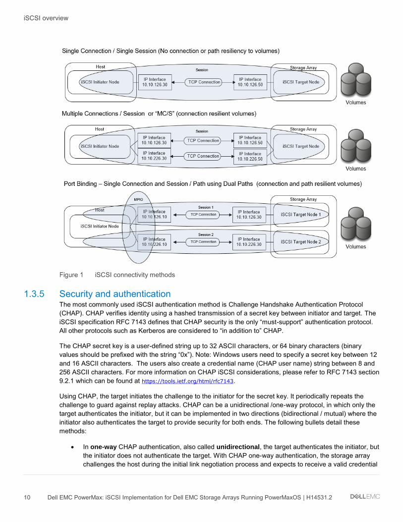
1. The process starts with an application on a host generating a block level I/O (layer 7) 2. The I/O is sent to the presentation layer 6 where the I/O is translated to the SCSI command set. 3. At the session layer 5 (where iSCSI operates), the iSCSI protocol encapsulates the SCSI commands
and assembles them into packets called Protocol Data Units (PDUs). 4. These PDUs are then sent to the Transport Layer 4, where it is encapsulated in a TCP segment (the i
in iSCSI). 5. It is then sent to the Network Layer 3 where it is placed into an IP datagram to form the TCP/IP
packet. 6. The TCP/IP packet is then placed into an Ethernet frame at the Datalink layer 2 7. The “iSCSI Ethernet” frame is then sent out onto the physical network layer 1 to be sent to the
storage target.
iSCSI overview
12 Dell EMC PowerMax: iSCSI Implementation for Dell EMC Storage Arrays Running PowerMaxOS | H14531.2
This process is shown in the following figure:
How iSCSI works
When the target side receives iSCSI Ethernet frames, the target datalink layer will remove the frame encapsulation and pass the results up to the Network Protocol Layer. The Network layer will remove the IP datagram encapsulation, and the Transport layer will remove the TCP segment encapsulation, leaving a PDU to be passed up to the session layer (iSCSI protocol layer). The iSCSI Protocol Layer will remove the SCSI data from the PDU and pass it to the presentation layer for interpretation and processing.
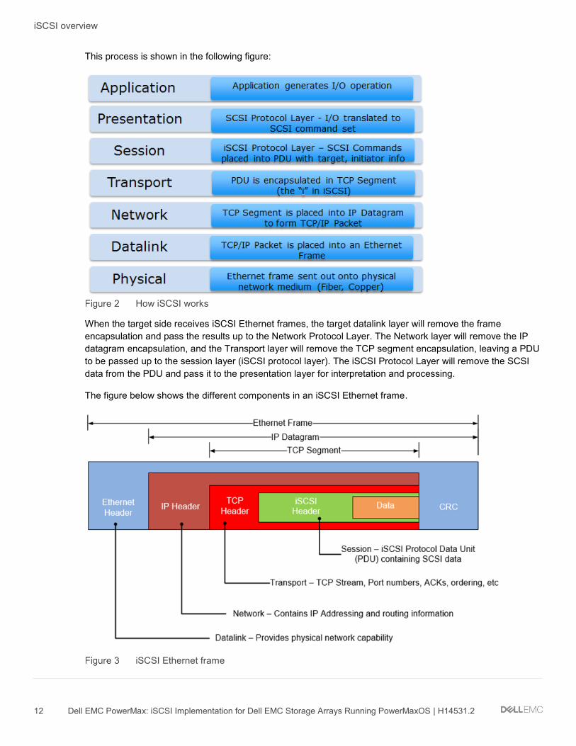
The figure below shows the different components in an iSCSI Ethernet frame.
iSCSI Ethernet frame

iSCSI overview
13 Dell EMC PowerMax: iSCSI Implementation for Dell EMC Storage Arrays Running PowerMaxOS | H14531.2
Essentially there is no difference between an iSCSI Ethernet frame with a standard Ethernet frame except what is the payload in the TCP segment - the iSCSI PDU. There is nothing in the TCP Segment Header to indicate that the TCP Data Segment contains data of a specific protocol. The TCP/IP definition does not prevent iSCSI PDUs and other network data from being transmitted on the same network. Similarly, there is nothing that requires that they be mixed, so a network administrator can determine whether an isolated subnet for iSCSI is necessary or not. The ability to carry multiple types of data in TCP Segment header is what allows modern Ethernet switches to the transport of iSCSI, IP, and Fibre Channel over Ethernet (FCoE) on the same infrastructure.
1.5 How iSCSI compares with other storage transport protocols The diagram below shows the similarities and differences between iSCSI and other storage transport mechanisms. All use the standard network layer model but only iSCSI uses the standard IP protocol.
iSCSI compared to other SCSI transports
The primary storage transport protocols currently deployed in the datacenter today is Fibre Channel and Serial Attached SCSI (SAS) storage. With the proliferation of 10 GbE networks and movement to lower cost converged infrastructures in the datacenter over the last few years, iSCSI has seen a significant uptick in deployment. FCoE has seen some uptick in deployment as well in footprint but it still lags far behind FC, SAS, and iSCSI. This is primarily because FCoE requires Ethernet to be a lossless network which requires the implementation of additional technologies such as end to end Data Center Bridging (DCB). These additional requirements add cost and complexity to the Ethernet solution, greatly reducing any cost advantages that Ethernet has over traditional Fibre Channel.
iSCSI overview
14 Dell EMC PowerMax: iSCSI Implementation for Dell EMC Storage Arrays Running PowerMaxOS | H14531.2
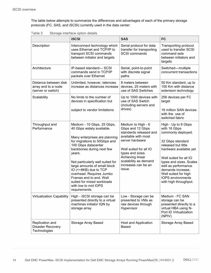
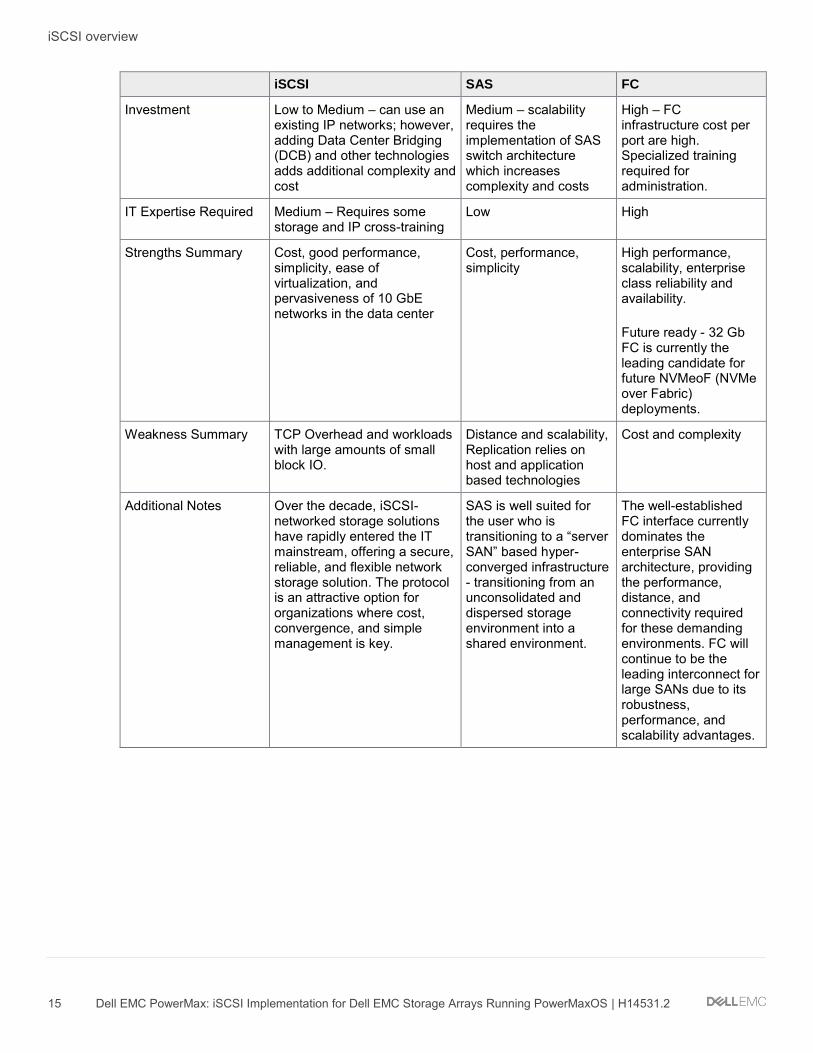
The table below attempts to summarize the differences and advantages of each of the primary storage protocols (FC, SAS, and iSCSI) currently used in the data center:
Storage interface option details iSCSI SAS FC
Description Interconnect technology which uses Ethernet and TCP/IP to transport SCSI commands between initiator and targets
Serial protocol for data transfer for transporting SCSI commands
Transporting protocol used to transfer SCSI command sets between initiators and targets
Architecture IP-based standard— SCSI commands send in TCP/IP packets over Ethernet
Serial, point-to-point with discrete signal paths
Switched—multiple concurrent transactions
Distance between disk array and to a node (server or switch)
Unlimited, however, latencies increase as distances increase
8 meters between devices, 25 meters with use of SAS Switches
50 Km standard, up to 100 Km with distance extension technology
Scalability No limits to the number of devices in specification but
subject to vendor limitations
Up to 1000 devices with use of SAS Switch (including servers and drives)
256 devices per FC target
16 million SAN devices with the use of switched fabric
Throughput and Performance
Medium - 10 Gbps, 25 Gbps, 40 Gbps widely available.
Many enterprises are planning for migrations to 50Gbps and 100 Gbps datacenter backbones during next few years.
Not particularly well suited for large amounts of small block IO (<=8KB) due to TCP overhead. Requires Jumbo Frames end to end. Well suited for mixed workloads with low to mid IOPS requirements.
Medium to High - 6 Gbps and 12 Gbps standards released and available with most server hardware
Well suited for all IO types and sizes. Achieving linear scalability as demand increases can be an issue.
High - Up to 8 Gbps with 16 Gbps commonly deployed.
32 Gbps standard released but little hardware available yet
Well suited for all IO types and sizes. Scales well as performance demands increase. Well suited for high IOPS environments with high throughput.
Virtualization Capability
High - iSCSI storage can be presented directly to a virtual machines initiator IQN by storage array
Low - Storage can be presented to VMs as raw devices through Hypervisor
Medium - FC SAN storage can be presented directly to a virtual HBA using N-Port ID Virtualization (NPIV)
Replication and Disaster Recovery Technologies
Storage Array Based Host and Application Based
Storage Array Based
iSCSI overview
15 Dell EMC PowerMax: iSCSI Implementation for Dell EMC Storage Arrays Running PowerMaxOS | H14531.2
iSCSI SAS FC
Investment Low to Medium – can use an existing IP networks; however, adding Data Center Bridging (DCB) and other technologies adds additional complexity and cost
Medium – scalability requires the implementation of SAS switch architecture which increases complexity and costs
High – FC infrastructure cost per port are high. Specialized training required for administration.
IT Expertise Required Medium – Requires some storage and IP cross-training
Low High
Strengths Summary Cost, good performance, simplicity, ease of virtualization, and pervasiveness of 10 GbE networks in the data center
Cost, performance, simplicity
High performance, scalability, enterprise class reliability and availability.
Future ready - 32 Gb FC is currently the leading candidate for future NVMeoF (NVMe over Fabric) deployments.
Weakness Summary TCP Overhead and workloads with large amounts of small block IO.
Distance and scalability, Replication relies on host and application based technologies
Cost and complexity
Additional Notes Over the decade, iSCSI-networked storage solutions have rapidly entered the IT mainstream, offering a secure, reliable, and flexible network storage solution. The protocol is an attractive option for organizations where cost, convergence, and simple management is key.
SAS is well suited for the user who is transitioning to a “server SAN” based hyper-converged infrastructure - transitioning from an unconsolidated and dispersed storage environment into a shared environment.
The well-established FC interface currently dominates the enterprise SAN architecture, providing the performance, distance, and connectivity required for these demanding environments. FC will continue to be the leading interconnect for large SANs due to its robustness, performance, and scalability advantages.

iSCSI overview
16 Dell EMC PowerMax: iSCSI Implementation for Dell EMC Storage Arrays Running PowerMaxOS | H14531.2
iSCSI SAS FC
Optimal Environments SMBs and enterprise, departmental and remote offices. Very well suited for converged infrastructures and application consolidation.
• Business applications running on top of smaller to mid- sized Oracle environments
• All Microsoft Business Applications such as Exchange, SharePoint, SQL Server
Infrastructures requiring close proximity to all devices (hyper-converged infrastructures)
• Transaction-sensitive databases
• Data streaming
• All Microsoft Business Applications such as Exchange, SharePoint, SQL Server
Enterprise with complex SANs: high number of IOPS and throughput
• Non-stop corporate backbone including Mainframe
• High intensity OLTP/OLAP transaction processing for Oracle, IBM DB2, Large SQL Server databases
• Quick response network for imaging and data warehousing
• All Microsoft Business Applications such as Exchange, SharePoint, SQL Server
The above table outlines the strengths and weaknesses of the various storage interface options as a storage interface for SMB and enterprise level SAN. Each customer has their own set of unique criteria to use in evaluating different storage interface for their environment. For most small enterprise and SMB environments looking to implement a converged, virtualized environment, the determining factors for a storage interface are up-front cost, scalability, hypervisor integration, availability, performance, and the amount of IT Expertise required to manage the environment. The above table shows that iSCSI provides a nice blend of these factors. When price versus performance is compared across all of the technologies, iSCSI is more than competitive with SAS and FC. In many data centers, particularly in the SMB space, many environments are not pushing enough IOPS to saturate even one Gbps bandwidth levels. At the time of this writing, 10 Gbps networks are becoming legacy in the datacenter and 25 Gbps networks are being more commonly deployed for a network backbone. This makes iSCSI a real option for future growth and scalability as throughput demands increase. Another reason that iSCSI is considered an excellent match for converged virtualized environments, is that iSCSI fits in extremely well with a converged network vision. Isolating iSCSI NICs on a virtualized host allows each NIC to have its own virtual switch and specific QoS settings. Virtual machines can be provisioned with iSCSI storage directly through these virtual switches, bypassing the management OS completely and reducing I/O path overhead.
Making a sound investment in the right storage protocol is for a critical step for any organization. Understanding the strengths and weaknesses of each of the available technologies is essential. By choosing the iSCSI protocol, a customer will be able to implement a lower cost SAN which can meet the vast majority of its converged, and virtualized workloads.
iSCSI overview
17 Dell EMC PowerMax: iSCSI Implementation for Dell EMC Storage Arrays Running PowerMaxOS | H14531.2
1.6 Deployment considerations for iSCSI The following information needs to be considered and understood when deploying iSCSI into an environment.
1.6.1 Network considerations Network design is key to making sure iSCSI works properly and delivers the expected performance in any environment. The following are best practice considerations for iSCSI networks:
• 10GbE networks are essential for enterprise production level iSCSI. Anything less than 10GbE should be relegated to test and development.
• iSCSI should be considered a local-area technology, not a wide-area technology, because of latency issues and security concerns.
• Segregate iSCSI traffic from general traffic by using either separate physical networks or layer-2 VLANs. Best practice is to have a dedicated LAN for iSCSI traffic and not share the network with other network traffic. Aside from minimizing network congestion, isolating iSCSI traffic on its own physical network or VLAN is considered a must for security as iSCSI traffic is transmitted in an unencrypted format across the LAN.
• Implement jumbo frames (by increasing the default network MTU from 1500 to 9000) in order to deliver additional throughput especially for small block read and write traffic. However, care must be taken if jumbo frames are to be implemented as they require all devices on the network to be jumbo frame compliant and have jumbo frames enabled. When implementing jumbo frames, set host and storage MTUs to 9000 and set switches to higher values such as 9216 (where possible).
• To minimize latency, avoid routing iSCSI traffic between hosts and storage arrays. Try to keep hops to a minimum. Ideally host and storage should coexist on the same subnet and be one hop away maximum.
• Enable “trunk mode” on network switch ports. Many switch manufacturers will have their switch ports set using “access mode” as a default. Access mode allows for only one VLAN per port and is assuming that only the default VLAN (VLAN 0) will be used in the configuration. Once an additional VLAN is added to the default port configuration, the switch port needs to be in trunk mode, as trunk mode allows for multiple VLANs per physical port.
1.6.2 Multipathing and availability considerations The following are iSCSI considerations with regard to multi-pathing and availability:
• Deploy port binding iSCSI configurations with multipathing software enabled on the host rather than use a multiple connections per session (MC/S) iSCSI configuration. MC/S was created when most host operating systems did not have standard OS level multipathing capabilities. MC/S is prone to command bottlenecks at higher IOPS. Also, there is inconsistent support for MC/S across vendors
• Use the "Round Robin (RR)" load balancing policy for Windows host based multipathing software (MPIO) and Linux systems using DM-Multipath. Round Robin uses an automatic path selection rotating through all available paths, enabling the distribution of load across the configured paths. This path policy can help improve I/O throughput. For active/passive storage arrays, only the paths to the active controller will be used in the Round Robin policy. For active/active storage arrays, all paths will be used in the Round Robin policy.
- For Linux systems using DM-Multipath, change “path_grouping_policy” from “failover” to “multibus” in the multipath.conf file. This will allow the load to be balanced over all paths. If one fails, the load will be balanced over the remaining paths. With “failover” only a single path will be

iSCSI overview
18 Dell EMC PowerMax: iSCSI Implementation for Dell EMC Storage Arrays Running PowerMaxOS | H14531.2
used at a time, negating any performance benefit. Ensure that all paths are active using “multipath –l” command. If paths display an “enabled” status, they are in failover mode
• Use the “Symmetrix Optimized” algorithm for Dell EMC PowerPath software. This is the default policy and means that administrators do not need to change or tweak configuration parameters. PowerPath selects a path for each I/O according to the load balancing and failover policy for that logical device. The best path is chosen according to the algorithm. Due to the propriety design and patents of PowerPath, the exact algorithm for this policy cannot be detailed here
• Do not use NIC teaming on NICs dedicated for iSCSI traffic. Use multipathing software such as native MPIO or PowerPath for path redundancy.
1.6.3 Resource consumption considerations When designing an iSCSI SAN, one of the primary resource consideration must be focused around the CPU consumption required to process the iSCSI traffic throughput on both the host initiator and storage array target environments. As a general rule of thumb, network traffic processing typically consumes 1 GHz of CPU cycles for every 1 Gbps (125 MBps) of TCP throughput. It is important to note that TCP throughput can vary greatly depending on workload; however, many network design teams use this rule to get a “ball park” idea of CPU resource sizing requirements for iSCSI traffic. The use of this rule in sizing CPU resources is best shown by an example.
Consider the following: the total throughput of an iSCSI workload is estimated to be 2.5 GBps. This means that both the host and storage environments must be sized properly from a CPU perspective to handle the estimated 2.5 GBps of iSCSI traffic. Using the general rule of thumb, processing the 2.5 GBps of iSCSI traffic will consume:
2.5 𝐺𝐵𝑝𝑠 𝑥 (1000 𝑀𝐵𝑝𝑠
1 𝐺𝐵𝑝𝑠) 𝑥 (
1 𝐺𝐻𝑧
125 𝑀𝐵𝑝𝑠) = 20 GHz of CPU consumption
This means that an estimated 20 GHz of CPU resources will be consumed on both the host initiator and storage array target side of the environment to process the iSCSI traffic. To further examine the impact of this requirement, say the host initiator environment consists of a heavily virtualized dual node cluster. Each node has 2 x 16 core 2.5 GHz CPUs. This means that the host initiator environment has a total of:
2 𝑛𝑜𝑑𝑒𝑠 𝑥 ( 2 𝐶𝑃𝑈𝑠
𝑛𝑜𝑑𝑒) 𝑥 (
16 𝑐𝑜𝑟𝑒𝑠
𝐶𝑃𝑈 ) 𝑥 (
2.5 𝐺𝐻𝑧
𝑐𝑜𝑟𝑒 ) = 160 GHz of CPU processing power
The estimated consumption of 20 GHz CPU cycles to process the 2.5 GBps of iSCSI traffic represents 12.5% of the total 160 GHz processing power of the host initiator environment. In many virtualized environments, a two node cluster is considered a small implementation. Many modern virtualized environments will consist of many nodes, with each node being dual CPU and multi-core. In these environments, 20 GHz of CPU consumption might seem trivial; however, in heavily virtualized environments, every CPU cycle is valuable. CPU resource conservation is even more important on the storage side of the environment as CPU resources are often much more limited than on the host initiator side.
The impact on CPU resources by iSCSI traffic can be minimized by deploying the following into the iSCSI SAN environment:
• In order to fully access the environment CPU resources, widely distribute the iSCSI traffic across many host nodes and storage directors ports as possible.
iSCSI overview
19 Dell EMC PowerMax: iSCSI Implementation for Dell EMC Storage Arrays Running PowerMaxOS | H14531.2
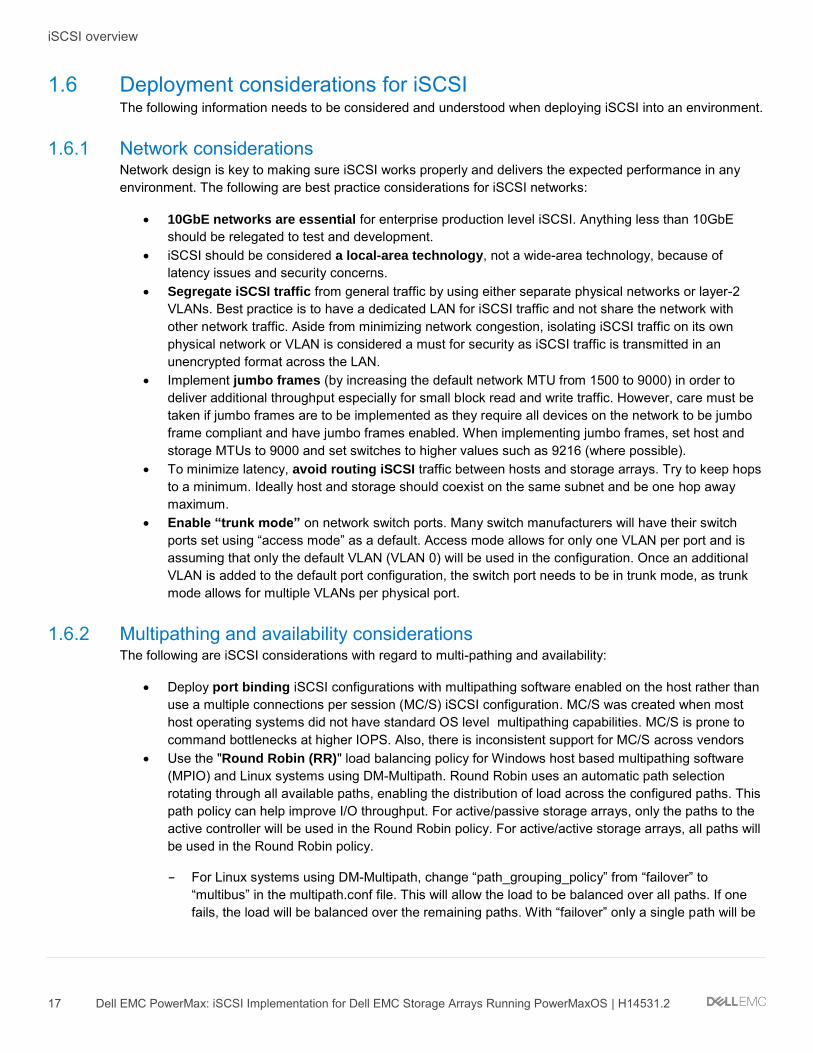
• Employ NICs with a built in TCP Offload Engine (TOE). TOE NICs offload the processing of the datalink, network, and transport layers from the CPU and process it on the NIC itself.
• For heavily virtualized servers, use NICs which support Single Root - IO Virtualization (SR-IOV). Using SR-IOV allows the guest to bypass the hypervisor and access I/O devices (including iSCSI) directly. In many instances, this can significantly reduce the server CPU cycles required to process the iSCSI I/O.
Note: The introduction of TOE and SR-IOV into an iSCSI environment can add complexity and cost. Careful analysis must be done to ensure that the additional complexity and cost is worth the increased performance.

PowerMaxOS iSCSI implementation overview
20 Dell EMC PowerMax: iSCSI Implementation for Dell EMC Storage Arrays Running PowerMaxOS | H14531.2
2 PowerMaxOS iSCSI implementation overview EMC has implemented iSCSI connectivity on PowerMaxOS based storage arrays with the introduction of a iSCSI target model which is architected to support true multi-tenancy. The PowerMaxOS iSCSI target model is primarily being driven by market needs originating from the cloud/service provider space, converging infrastructures, and heavily virtualized environments where slices of infrastructure (e.g., Compute, Network and Storage) are assigned to different users (tenants). This model requires control and isolation of resources along with multi-tenancy capabilities not previously attainable with previous iSCSI implementations on previous generation of the VMAX.
2.1 Background The implementation of iSCSI on as many storage vendors closely follows the same model as FC and FCoE emulations where a user is presented a physical port linked together with a target node along with a pool of associated devices. Through the use of masking, users could then provision LUNs to individual hosts connected to this target. Besides LUN masking, this model provides almost no isolation and control of software and hardware resources on a per tenant basis. As a result, if a tenant required partial ownership of the IO stack, which is normally expected in cloud service environments, then each tenant would need to access its own physical port. In this type of situation, scalability immediately becomes a major obstacle with this design as front end port counts on storage arrays are limited. Security and lack of network isolation are other concerns with the current model, as resources (e.g. volumes, authentication information) are shared among otherwise independent tenants.
2.2 The PowerMaxOS iSCSI implementation design objectives The PowerMaxOS iSCSI target model has been designed from the ground up to meet customer demands regarding control and isolation of resources, as well as providing a platform for greater physical port utilization and efficiencies - allowing customers to build true multi-tenant environments on the PowerMax platform. The PowerMaxOS iSCSI target model accomplishes this by the following key design principles:
• PowerMaxOS groups director CPU resources (cores) together into logical pools. Each director dynamically allocates these pooled CPU resources to meet the workload demands placed upon the different types of front end and back end connectivity options the director supports. These connectivity options and the resources they use are called “emulation instances”. PowerMaxOS supports iSCSI using the “SE instance”. A PowerMax director can have only one SE instance. The SE instance is dynamically allocated a certain amount of cores which are used to process the total amount of TCP traffic coming in through the director’s 10 GbE ports.
• Separation of the iSCSI Target Node from the physical port. This allows users to create individual target nodes without restrictions related to the number of mapped physical ports to specific SE instances.
• Individual iSCSI targets can be assigned one or more IP interfaces, which define access network paths for hosts to reach the target node.
• The implementation supports configuration of VLANs, defining internal Network IDs, and routing information.
• Storage side Quality of Service (QoS) is implemented at storage group (SG) level using host I/O limits and PowerMaxOS service levels.
• The PowerMaxOS iSCSI implementation does not support priority flow control (PFC) or data center bridging (DCB)

PowerMaxOS iSCSI implementation overview
21 Dell EMC PowerMax: iSCSI Implementation for Dell EMC Storage Arrays Running PowerMaxOS | H14531.2
2.3 PowerMaxOS iSCSI implementation core components The PowerMaxOS iSCSI model achieves the design objectives by using the core components:
• A 4 x 10GbE port interface module (required hardware) • The PowerMaxOS iSCSI Target Node • The PowerMaxOS iSCSI IP Interface • CHAP Authentication • IP Routing
These new objects provide a significant amount of flexibility and allow users to define how to mix and match target nodes and IP interfaces over mapped physical ports. An example of using these components to create a multi-tenant environment sharing a single port is shown in the diagram below. Each of these components will be detailed in the sections which follow.
Typical PowerMaxOS iSCSI multi-tenant architecture
2.3.1 Hardware: Quad Port 10GbE Interface Module The PowerMaxOS iSCSI target implementation uses a quad port 10GbE hardware I/O module. This module has the following features:
• High density quad-port 10GbE interface (4 SFP+ optical transceiver connectors) • Support for up to 4 Modules / SE instance (maximum of 16 x 10GbE Ports / SE Instance) • Emulex’s Lancer Multiprotocol IO Controller • FRU and Hot Swappable • Dimensions: 3” w x 1.25” h x 7.875”
2.3.2 PowerMaxOS iSCSI target node The PowerMaxOS iSCSI target node is the backbone on how iSCSI is implemented on the PowerMax storage arrays. One can think of each PowerMaxOS iSCSI Target node as a virtual port as each physical port can have up to 64 targets. These target nodes are created and configured at the user’s discretion. An exception being the “bootstrapping target”, which can come preconfigured on a new all iSCSI PowerMax system. The bootstrapping target allows for initial target configuration on the system so that management hosts can discover and access the new storage array; however, with the introduction of Embedded Management, the user can remotely “http” to the embedded Unisphere on the storage array and create the initial iSCSI target; thus reducing the need for a factory pre-configured bootstrap target.

PowerMaxOS iSCSI implementation overview
22 Dell EMC PowerMax: iSCSI Implementation for Dell EMC Storage Arrays Running PowerMaxOS | H14531.2
The number of target nodes a user can configure is constrained to:
• Maximum of 64 targets per physical port • Designed for maximum of 512 targets per director
An iSCSI Target can be in one of the two logical states: online or offline. Semantically these two states resemble the behavior of “port online” or “port offline”, where the online state indicates the Target Node is ready to accept and execute IO requests, and the latter one indicates it isn’t. Users will be able to control the target state through Unisphere™ and Solutions Enabler commands.
Most of the time (as is the case with port state) the Target Node will be in an online state. There are three common situations when the state will be offline:
• All newly created targets are in the offline state by default • Configuration changes to the existing Target Node: all subsequent changes of Target attributes (e.g.
changing Target name) affect host connectivity in a detrimental way and require a specific Target to be in the offline state.
• For debugging, security and/or other reasons, users may want to have a specific Target in the offline state and thus prevent any IO activity from hosts that are connected to this Target.
Another feature provided by the iSCSI target is device separation along target node lines. Devices that were previously provisioned on a per port basis are now allocated on a per Target basis. For example, if two Target Nodes are created for two different users (tenants) on the same SE instance, the new model allows for separation of devices assigned to each target, cleanly isolating each user’s data from each other (true multi-tenancy), but this is not a requirement and users can technically still assign the same device to several iSCSI Targets on the same director (even though a use case for this would be hard to justify). A top-level limitation is that the same volume cannot be assigned to more than 32 different Targets on the same director.
To create an iSCSI target on PowerMax, a user must supply:
• The physical director which is configured with the SE emulation • A user defined IQN (Note: If a user does not supply an IQN, one will be auto-generated) • A Network ID: A Network ID is PowerMaxOS construct which is which is used internally by the system
to associate an array IP interface with an array iSCSI target. The PowerMaxOS Network ID is specific to a single physical port on the array and is not visible to external switches or hosts. A current limitation with the implementation is that a target cannot incorporate multiple network IDs, therefore cannot span multiple physical ports.
The user can optionally specify a TCP port for the target (default is port 3260 is used if none is specified).
In the PowerMaxOS iSCSI implementation, port flags which previously needed to be set on the physical port are now set on the iSCSI target. Valid iSCSI target port flags are:
• SOFT_RESET • ENVIRON_SET • DISABLE_Q_RESET_ON_UA • AVOID_RESET_BROADCAST • SCSI_3 • SPC2_PROTOCOL_VERSION • SCSI_SUPPORT1 • VOLUME_SET_ADDRESSING

PowerMaxOS iSCSI implementation overview
23 Dell EMC PowerMax: iSCSI Implementation for Dell EMC Storage Arrays Running PowerMaxOS | H14531.2
• OPENVMS • ISID_PROTECTED
Note: The SCSI_3, SPC2_PROTOCOL_VERSION, and SCSI_SUPPORT1 flags are enabled by default when a target is created on PowerMax
2.3.2.1 Creating a PowerMaxOS iSCSI Target using Solutions Enabler Below are Solutions Enabler commands which can be used to create an iSCSI target:
symconfigure -sid 0248 -cmd "create iscsi_tgt dir 1E, iqn=iqn.emc.0248.tenant1,
network_id=80;" commit -noprompt
The following Solutions Enabler command creates an iSCSI target along with enabling the VOLUME_SET_ADDRESSING flag:
symconfigure -sid 0248 -cmd "create iscsi_tgt dir 1E, iqn=iqn.emc.0248.tenant1,
network_id=80, VOLUME_SET_ADDRESSING=Enable;" commit -noprompt
2.3.2.2 Creating a PowerMaxOS iSCSI Target using Unisphere To create an iSCSI target using Unisphere for VMAX, the user selects a VMAX3 or VMAX All Flash storage array; then navigates to the iSCSI dashboard in “System”; and selects “Create iSCSI Target”. The create iSCSI target wizard is shown in the screen shot below:
Creating an iSCSI Target using Unisphere for PowerMax

PowerMaxOS iSCSI implementation overview
24 Dell EMC PowerMax: iSCSI Implementation for Dell EMC Storage Arrays Running PowerMaxOS | H14531.2
After entering the required data, the user then selects OK to create the target.
Note: By clicking “Advanced Options”, the user can set the port flags. The SCSI_3, SPC2_PROTOCOL_VERSION, and SCSI_SUPPORT1 flags are enabled by default when a target is created on PowerMax
2.3.3 PowerMaxOS iSCSI IP interface IP interfaces provide access to Target Nodes through one or more network paths. Similar to the iSCSI Target object, IP interfaces are managed by users, where they can create, modify, erase and map them to an individual iSCSI Target. The number of IP interfaces a user can configure is constrained to:
• Maximum of 8 per target node • Maximum of 64 per physical port • Maximum of 1024 per engine (512 per director) • A single IP Interface can be mapped to a single iSCSI target
To create a IP Interface on PowerMax, a user supplies:
• IP Address (either IPv4 or IPv6) • Netmask for IP address provided as prefix length • VLAN: VLAN tag information. If no VLAN is configured or not specified, the default value of zero (0) is
used. • Physical Director: Like the iSCSI target, an IP Interface can only be mapped to a single physical
director using SE emulation. • Physical Port number: The physical port number on the director the IP Interface is attached to. • Network ID: A Network ID is PowerMaxOS construct which is which is used internally by the system
to associate an array IP interface with an array iSCSI target. The PowerMaxOS Network ID is specific to a single SE instance on the array and is not visible to external switches or hosts. Default value is 0, range is 0-511.
• MTU size: This is an optional parameter which sets the maximum transmit size of Ethernet packet for the IP Interface. If not specified, the portal uses the default of 1500. To enable jumbo frames, set MTU to 9000 (maximum value allowed).
IP Interface configuration constraints:
• The IP Interface’s IP address and subnet must be unique per Network ID. A current limitation with the target implementation is that a target cannot span multiple network IDs.
• Maximum number of IP Interfaces mapped to one iSCSI Target is eight and a single IP Interface can be mapped to only one iSCSI Target.
• VLAN tag must be unique per physical port. VLAN tag zero implies there is no VLAN assigned. • The Network ID values of IP Interfaces mapped to an individual Target must be all the same.
2.3.3.1 Creating a PowerMaxOS IP interface using Solutions Enabler Below is a Solutions Enabler command which will create an iSCSI IP Interface with an MTU size of 9000:
symconfigure -sid 0248 -cmd "create ip_interface dir 1E port 8,
ip_address=192.168.80.10, ip_prefix=24,network_id=80, vlanid=80, mtu=9000;"
commit -noprompt
PowerMaxOS iSCSI implementation overview
25 Dell EMC PowerMax: iSCSI Implementation for Dell EMC Storage Arrays Running PowerMaxOS | H14531.2
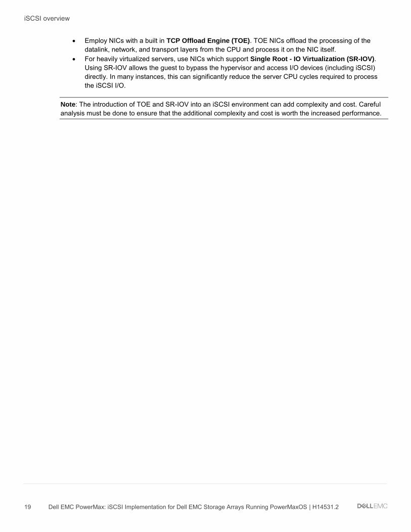
2.3.3.2 Creating a PowerMaxOS IP interface using Unisphere To create an iSCSI IP Interface using Unisphere, the user selects a storage array; then navigates to the iSCSI dashboard in “System”; and selects “Create IP Interface”. The create iSCSI IP Interface wizard is shown in the screen shot below:
Creating a PowerMaxOS iSCSI IP Interface using Unisphere for VMAX
After entering the required information, the user selects OK to create the IP interface.
2.3.4 CHAP authentication The PowerMaxOS iSCSI implementation supports CHAP (Challenge Handshake Authentication Protocol) for initiators and targets. The implementation supports two types of CHAP authentication:
• One-way CHAP - In one-way CHAP authentication, also called unidirectional, the target authenticates the initiator, but the initiator does not authenticate the target.
• Two-way CHAP - In two-way CHAP authentication, also called bidirectional or mutual, an additional level of security enables the initiator to authenticate the target.

PowerMaxOS iSCSI implementation overview
26 Dell EMC PowerMax: iSCSI Implementation for Dell EMC Storage Arrays Running PowerMaxOS | H14531.2
2.3.4.1 Setting one-way CHAP authentication With CHAP one-way authentication, the storage array challenges the host initiator during the initial link negotiation process and expects to receive a valid credential and CHAP secret in response. When challenged, the host initiator transmits a CHAP credential and CHAP secret to the storage array. The storage array looks for this credential and CHAP secret which stored in the host initiator’s initiator group (IG) information in the ACLX database. Once a positive authentication occurs, the storage array sends an acceptance message to the host. However, if the storage array fails to find any record of the credential/secret pair, it sends a rejection message, and the link is closed.
CHAP Constraints:
• The CHAP protocol secret value is a user-defined string up to 32 ASCII characters, or 64 binary characters (binary values should be prefixed with the string “0x”) for UNIX users. Windows users need to specify a secret between 12 and 16 characters and a credential name string between 8 and 256 characters.
• Currently CHAP can only be set up using Solutions Enabler SYMCLI commands. • The host initiator IQN must be in an initiator group prior to setting one-way CHAP as the initiator
CHAP information is stored in the ACLX database for the initiator group. The initiator group does not need to be in a masking view (MV) at the time CHAP is enabled.
• Masking views are intended to provide storage isolation for specific initiators; while CHAP provides authentication.
• The use of Radius servers to store CHAP authentication data is not currently supported. This is under consideration for a future release.
• PowerMaxOS iSCSI currently does not support RADIUS for CHAP authentication. Radius support is under consideration for a future release but this support is dependent upon customer demand.
Setting iSCSI one-way CHAP authentication on PowerMax requires:
• The PowerMax storage array System ID (SID) • The host initiator IQN • The user defined credential the host initiator will use to log into the storage array with (often the host
initiator IQN) • A specific secret (password) the host needs to present to the storage array.
The following SYMCLI command enables one-way CHAP for the iSCSI initiator (iqn.1991-05.com.microsoft.lcseb130) on the storage array :
symaccess -sid 0248 –iscsi iqn.1991-05.com.microsoft:lcseb130 set chap –cred
iqn.1991-05.com.microsoft:lcseb130 –secret <TargetSecret>
In the above “symaccess set chap” command, the –cred and –secret flags specify the credential and target password the specific host initiator (specified by the –iscsi flag) will need to send to the storage array for authentication.

PowerMaxOS iSCSI implementation overview
27 Dell EMC PowerMax: iSCSI Implementation for Dell EMC Storage Arrays Running PowerMaxOS | H14531.2
On a Windows host, the specific host credential and the target secret it passes to the storage array can be found and customized using the in the advanced settings frame of Windows iSCSI Initiator Tool (see screen shot below).
Customizing the host credential and target secret in the iSCSI Initiator Tool
The values in the “Name” and “Target secret” text boxes on the advanced properties frame must match exactly the values entered in the –cred and –secret parameters used by the “symaccess set chap” command. Note that the values are case sensitive. If there is a mismatch in either of these values, the host will not be able to authenticate on the storage array.
In the Windows iSCSI Tool, the host initiator IQN is always the default value used in the “Name” text box in the advanced settings frame. For easier management of Windows hosts on the storage array, use the Windows host IQN value for the –cred parameter in the “symaccess set chap” command. In most cases, Windows administrators will leave the default value (the host initiator IQN) in “Name” text box in advanced settings. If at some point the Windows administrator changes this value, then they must inform the storage administrator of this change as this will create a credential mismatch for the initiator on the PowerMax array. The host initiator will no longer be able to authenticate to the target and will lose access to its storage unless the “symaccess set chap” command is re-run for the initiator using the new credential value.

PowerMaxOS iSCSI implementation overview
28 Dell EMC PowerMax: iSCSI Implementation for Dell EMC Storage Arrays Running PowerMaxOS | H14531.2
To examine the one-way CHAP credentials set up for the host initiator on the storage array, use the symaccess show <initiator group> command with the –detail flag using the name initiator group that the host initiator resides in:
symaccess -sid 0248 show lcseb130 -type initiator –detail
Symmetrix ID : 000196800248
Initiator Group Name : lcseb130
Last update time : 11:41:11 AM on Thu Aug 13,2015
Group last update time: 11:41:11 AM on Thu Aug 13,2015
Port Flag Overrides : No
Consistent Lun : No
iSCSI Name : iqn.1991-05.com.microsoft:lcseb130
User-generated Name : /
FCID Lockdown : N/A
Heterogeneous Host : No
Port Flag Overrides : No
CHAP Enabled : Yes
CHAP Credential : iqn.1991-05.com.microsoft:lcseb130
Type : iSCSI
In the above command, the host initiator IQN “iqn.1991-05.com.microsoft:lcseb130” has been previously placed into an initiator group named “lcseb130”. Again, this initiator group does not have to be in a masking view at the time one-way CHAP is enabled.
To disable CHAP authentications from an initiator use the following command:
symaccess -sid 0248 –iscsi iqn.1991-05.com.microsoft:lcseb130 disable chap
2.3.4.2 Setting two-way CHAP authentication Configuring two-way authentication between the host initiator and storage array iSCSI target requires the configuration of one-way authentication for the host initiator (as described in the previous section).
With two-way CHAP authentication, the host challenges and authenticates the storage array iSCSI targets also. This provides an extra layer of authentication and security in the iSCSI configuration as both the target and initiator act as authenticators and peers.

PowerMaxOS iSCSI implementation overview
29 Dell EMC PowerMax: iSCSI Implementation for Dell EMC Storage Arrays Running PowerMaxOS | H14531.2
In two way authentication, each target visible to the host must present an appropriate secret back to the host. In Windows, the initiator secret which the targets must present back to the host is set up in the Windows iSCSI Initiator tool Configuration tab as shown below:
Setting the initiator secret using the Windows iSCSI Tool
This can also be accomplished by using the “set-IscsiChapSecret” PowerShell cmdlet on the host:
[LCSEB129] PS C:\ >Set-IscsiChapSecret -ChapSecret <InitiatorCHAPSecret>
On the PowerMax array, two-way CHAP authentication is set up on the target using the following command:
symaccess -sid 0248 -iqn iqn.emc.0248.1E.prod set chap -cred
iqn.emc.0248.1E.prod -secret <InitiatorCHAPSecret>
In the above command, the IQN of the PowerMax iSCSI target which will be authenticated by the host initiator is the value used in the –iqn parameter. The IQN of the PowerMax iSCSI target is the value used in the –cred parameter (how the target presents itself to the host initiator in discovery). The secret that the target needs to present to the host initiator (as specified in the Windows iSCSI Tool Configuration tab) is the value used in the –secret parameter. If storage is to be presented to a host initiator through multiple PowerMax iSCSI targets, then the above command will need to be run for each target that will present itself to the host in order for successful two-way CHAP authentication.
PowerMaxOS iSCSI implementation overview
30 Dell EMC PowerMax: iSCSI Implementation for Dell EMC Storage Arrays Running PowerMaxOS | H14531.2
Two-way CHAP authentication can also be set using the PowerMax iSCSI target’s associated director and virtual port combination as follows:
symaccess -sid 0248 –iscsi_dirport 1e:0 set chap -cred iqn.emc.0248.1E.prod -
secret <InitiatorCHAPSecret>
In the above command, the –iqn parameter has been replaced with the –iscsi_dirport parameter. A storage array iSCSI target’s associated director and virtual port can found using the following “symcfg” command:
symcfg -sid 0248 list -se all -iscsi_tgt
Symmetrix ID: 000196800248 (Local)
Dir:P NetId Status IQN
------- ----- ------- ------------------------------
01E:000 80 Online iqn.emc.0248.1E.prod
02E:000 81 Online iqn.emc.0248.2E.prod
To examine two-way CHAP authentication set up on the PowerMax array, run the following symaccess command:
symaccess -sid 0248 list chap
Symmetrix ID : 000196800248
Director Identification : SE-1E
Director Port : 000
iSCSI Target Name :
Protocol : CHAP
Identifier Type State Credential
------------------------ ----- -------- ------------------------
SE-1E:000 N/A ENABLED iqn.emc.0248.1E.prod
To delete CHAP from a specific PowerMaxOS iSCSI target, use the following command:
symaccess -sid 0248 –iqn iqn.emc.0248.1E.prod delete chap
2.3.5 Routing instance In many implementations, storage administrators are limited to one or two VLANs for their entire storage environment by their network teams. This is because VLANs can be expensive from a resource and management perspective which makes them somewhat of a precious commodity in many environments. In order to compensate for environments with limited VLAN availability, the iSCSI network will often use a lower subnet mask to accommodate a larger number of subnets and host initiator and storage target IP interface IP addresses. In these cases, the PowerMaxOS iSCSI model must be able to properly route the iSCSI traffic across the different subnets being used in the environment. This is the function if the routing instance object.

PowerMaxOS iSCSI implementation overview
31 Dell EMC PowerMax: iSCSI Implementation for Dell EMC Storage Arrays Running PowerMaxOS | H14531.2
A PowerMaxOS routing instance is associated with a specific network ID on a single director. A user can create a maximum of 1024 routing instance per engine. When creating a PowerMaxOS routing a user will need to specify:
• The director number • IP address of default gateway • Subnet Mask (prefix) • Network ID number • PowerMaxOS IP interface IP address
The following table lists some commonly used subnet masks in iSCSI environments:
Commonly used iSCSI subnets
Subnet Mask Total number of IP addresses
Netmask Number of subnets
/26 64 255.255.255.192 4
/25 128 255.255.255.128 2
/24 256 255.255.255.0 1
/23 512 255.255.254.0 2
/22 1024 255.255.252.0 4
/21 2048 255.255.248.0 8
/20 4096 255.255.240.0 16
/0 NA 0.0.0.0 NA
Note: Subnet mask 0.0.0.0/0 signifies all address visible on the network. In traditional networking best practice, the use of this subnet is discouraged because of the confusion in having a network and subnet with indistinguishable addresses; however in networks with a few IP addresses, it can function as a useful “catch all” subnet to allow for broadcast to all visible IP address and subnets.
2.3.5.1 Creating a PowerMaxOS iSCSI IP Route using Solutions Enabler A user can specify an IP route for a specific IP address on a director by the following Solutions Enabler SYMCLI command:
symconfigure -sid 0248 -cmd "add ip_route dir 1E, ip_address=0.0.0.0,
ip_prefix=0, gateway=192.168.80.1, network_id=80;" commit –nop
The above Solutions Enabler command will create a “catch all” routing instance which uses a default gateway of 192.168.80.1 for all IP interface IP address (0.0.0.0) and all subnets (0) using Network ID 80 on director 1E.
2.3.5.2 Creating a PowerMaxOS iSCSI IP Route using Unisphere A user can specify an IP route for a specific IP address on a director by the following Solutions Enabler SYMCLI command:

PowerMaxOS iSCSI implementation overview
32 Dell EMC PowerMax: iSCSI Implementation for Dell EMC Storage Arrays Running PowerMaxOS | H14531.2
To create an iSCSI IP Interface using Unisphere, the user selects a array; then navigates to the iSCSI dashboard in “System”; and selects “Add IP Route”. The Add iSCSI IP Route wizard is shown in the screen shot below:
Creating a PowerMaxOS Routing Instance using Unisphere
After entering the required information, the user selects OK to create the IP route.
2.4 PowerMaxOS iSCSI host connectivity limits The following table summarizes the host connectivity limits for PowerMaxOS iSCSI
PowerMaxOS iSCSI host connectivity limits
Component Maximum Values
Per 10 GbE Port Per SE Instance Per Director Per Engine
VLANs 64 512 512 1024
SE Instance NA NA 1 2
Physical 10 GbE Ports
NA 16 16 32(1)
Network IDs NA 512 512 1024
Routing Instances NA 1024 1024 2048
IP Interfaces 64 512 512 1024
iSCSI Targets 64 512 512 1024
Host Connections 2048 8192 8192 8192

PowerMaxOS iSCSI implementation overview
33 Dell EMC PowerMax: iSCSI Implementation for Dell EMC Storage Arrays Running PowerMaxOS | H14531.2
Component Maximum Values
Per 10 GbE Port Per SE Instance Per Director Per Engine
Host Sessions 64 512 512 1024
Host IQNs 512 512 512 1024
1. Maximums of 32 ports on the VMAX 250F and PowerMax 2000 and 24 ports on the VMAX 950F and PowerMax 8000
Summary
34 Dell EMC PowerMax: iSCSI Implementation for Dell EMC Storage Arrays Running PowerMaxOS | H14531.2
3 Summary The Dell EMC iSCSI implementation on PowerMaxOS based storage arrays provides a viable, lower cost connectivity method for customers who are looking at alternatives to Fibre Channel. The Dell EMC PowerMaxOS iSCSI model is architected to support true multi-tenancy and other needs being driven by the market. The model is a good fit the cloud/service provider space, converging infrastructures, and heavily virtualized environments where slices of infrastructure (e.g., Compute, Network and Storage) are assigned to different users (tenants).

Technical support and resources
35 Dell EMC PowerMax: iSCSI Implementation for Dell EMC Storage Arrays Running PowerMaxOS | H14531.2
A Technical support and resources Dell.com/support is focused on meeting customer needs with proven services and support.
Storage technical documents and videos provide expertise that helps to ensure customer success on Dell EMC storage platforms.
A.1 Related resources
Document Title Collateral Type Part Number
Dell EMC PowerMax Family Overview White Paper H17118
Dell EMC VMAX All Flash Family Overview White Paper H14920.3
Dell EMC Service Levels for PowerMaxOS White Paper H17108
Dell EMC Embedded Management on PowerMax, VMAX All Flash, and VMAX3
White Paper H16856
Data Reduction with Dell EMC PowerMax White Paper H17072
Dell EMC PowerMax Reliability, Availability, and Serviceability Technical Note
White Paper H17064
VMAX All Flash iSCSI Deployment Guide for Oracle Databases White Paper H15132.1
VMAX All Flash iSCSI Deployment Guide for Windows White Paper H15143
Recommended