1 |
Dell EMC Isilon OneFS SmartFlash © 2019 Dell Inc. or its subsidiaries.
DELL EMC ISILON ONEFS SMARTFLASH File System Caching Infrastructure
Abstract This white paper provides an introduction to Isilon SmartFlash, the foundation of the Isilon flash-based caching performance feature. The paper includes an overview of the OneFS caching architecture and describes the benefits of an SSD-based caching solution.
December 2019
WHITE PAPER
2 |
Dell EMC Isilon OneFS SmartFlash © 2019 Dell Inc. or its subsidiaries.
Revisions Version Date Comment
1.0 November 2013 Initial release for OneFS 7.1
2.0 June 2014 Updated for OneFS 7.1.1
3.0 November 2014 Updated for OneFS 7.2
4.0 June 2015 Updated for OneFS 7.2.1
5.0 November 2015 Updated for OneFS 8.0
6.0 September 2016 Updated for OneFS 8.0.1
7.0 April 2017 Updated for OneFS 8.1
8.0 November 2017 Updated for OneFS 8.1.1
9.0 February 2019 Updated for OneFS 8.1.3
10.0 April 2019 Updated for OneFS 8.2
11.0 August 2019 Updated for OneFS 8.2.1
12.0 December 2019 Updated for OneFS 8.2.2
Acknowledgements This paper was produced by the following:
Author: Nick Trimbee
The information in this publication is provided “as is.” Dell Inc. makes no representations or warranties of any kind with respect to the information in this publication, and specifically disclaims implied warranties of merchantability or fitness for a particular purpose. Use, copying, and distribution of any software described in this publication requires an applicable software license.
Copyright © Dell Inc. or its subsidiaries. All Rights Reserved. Dell, EMC, Dell EMC and other trademarks are trademarks of Dell Inc. or its subsidiaries. Other trademarks may be trademarks of their respective owners.
3 |
Dell EMC Isilon OneFS SmartFlash © 2019 Dell Inc. or its subsidiaries.
TABLE OF CONTENTS Introduction .......................................................................................... Error! Bookmark not defined. OneFS caching .................................................................................................................................... 4 OneFS cache architecture ................................................................................................................... 5 OneFS caching hierarchy..................................................................................................................... 5 OneFS cache coherency ..................................................................................................................... 6
Level 1 cache ..................................................................................................................................................................... 7 Level 2 cache ..................................................................................................................................................................... 8 Level 3 cache ..................................................................................................................................................................... 8 Cache level comparison ..................................................................................................................................................... 9 Read caching ................................................................................................................................................................... 10 Write caching – SmartCache and the coalescer .............................................................................................................. 11 Cache eviction .................................................................................................................................................................. 12 Cache prefetching ............................................................................................................................................................ 12 L3 cache persistence ....................................................................................................................................................... 13 Benefits of using SSDs for L3 cache ............................................................................................................................... 13 OneFS SSD strategy comparison .................................................................................................................................... 14 SSD compatibility ............................................................................................................................................................. 14 Enabling L3 cache ............................................................................................................................................................ 15 Cache monitoring & reporting .......................................................................................................................................... 16 Performance resource management ............................................................................................................................... 16 L3 cache and performance .............................................................................................................................................. 17 L3 cache sizing ................................................................................................................................................................. 17 L3 cache and Global Namespace Acceleration ............................................................................................................... 18
In-line Compression and Caching .................................................................................................................................... 18
L3 cache best practices ..................................................................................................................... 19 L3 cache considerations .................................................................................................................................................. 20
Conclusion ......................................................................................................................................... 21
4 |
Dell EMC Isilon OneFS SmartFlash © 2019 Dell Inc. or its subsidiaries.
Executive Summary Enterprises across the globe are witnessing an explosion in the growth of big data today. As these businesses continue to face the management challenges of this avalanche of large unstructured data, the ability to deliver greater performance from their storage systems while maintaining data consistency and availability for wide range of workflows also increases.
The caching of data and metadata is a common practice used to deliver high levels of performance and low latency in storage systems. Caching typically involves keeping the most frequently accessed data in memory, providing faster access by intelligently predicting how content will be accessed and the parts of a dataset that will be required.
In traditional scale-up NAS architectures, the cache located on a filer head processor is available only to the volumes stored on that device. Large deployments of these systems can consist of hundreds of volumes. As such, the sum total of cache on these systems may be very large, but its effectiveness is limited due to its partitioned nature. By way of contrast, Isilon’s caching architecture ensures that all storage nodes in an Isilon cluster leverage each other’s cache and efficiently utilize the large aggregate amount of memory (RAM) in a cluster, which can contain a file system in excess of 68 PB in size. Since each node contains RAM, the EMC® Isilon® OneFS® read and write caches scale linearly as the cluster grows in size.
Intended Audience This paper presents information for deploying and managing a Dell EMC Isilon cluster. This paper does not intend to provide a comprehensive background to the Isilon OneFS architecture.
Please refer to the OneFS Technical Overview white paper for further details on the OneFS architecture.
The target audience for this white paper is anyone configuring and managing an Isilon clustered storage environment. It is assumed that the reader has an understanding and working knowledge of the OneFS components, architecture, commands and features.
More information on OneFS commands and feature configuration is available in the OneFS Administration Guide.
OneFS caching The OneFS caching infrastructure enables Isilon to deliver extreme levels of performance, while maintaining globally coherent read and write access across the Isilon cluster. OneFS goes beyond traditional storage caching architectures in that it was designed from the ground up to leverage the distributed and highly parallel nature. While traditional scale-up storage systems typically have a fixed amount of cache per “head” unit (filer or server), Isilon’s clustered architecture ensures that as storage grows, so does the amount of cache available to the system. Furthermore, unlike traditional NAS and SAN systems, OneFS caching is globally coherent across the cluster, so cached data is available to any node in the cluster, regardless of which node it physically resides on. Cache sharing across a consolidated storage environment is critical for today’s large-scale storage deployments, in terms of performance, scalability, efficiency and overall cost of ownership.
Cache is typically used in storage systems to reduce the latency associated with retrieving data from disk, thereby improving performance for clients making read requests. It is also used to improve the performance of writes, by acknowledging the write to the client when it has been written to cache, and then writing the data in the cache to disk at a later time.
Until now, Isilon’s caching infrastructure has exclusively leveraged the system memory (RAM) and non-volatile memory (NVRAM) in each node. However, from OneFS 7.1.1 onwards, it’s been possible to enable the caching subsystem to utilize solid state drives (SSDs) and the increased capacity, affordability, and storage persistence that they offer.
Caching occurs in OneFS at multiple levels and for a variety of types of data. For this discussion we are focused on caching of file system structures in main memory and on SSD.
5 |
Dell EMC Isilon OneFS SmartFlash © 2019 Dell Inc. or its subsidiaries.
OneFS cache architecture The OneFS operating system caching infrastructure design is based on aggregating the cache present on each node in a cluster into one globally accessible pool of memory. To do this, Isilon uses an efficient messaging system, similar to non-uniform memory access (NUMA). This allows all the nodes’ memory cache to be available to each and every node in the cluster. Remote memory is accessed over an internal interconnect and has much lower latency than accessing hard disk drives.
For remote memory access, OneFS utilizes either an IP over Ethernet or Sockets Direct Protocol (SDP) over an Infiniband (IB) backend interconnect on the cluster, which is essentially a distributed system bus. SDP provides an efficient, socket-like interface between nodes which, by using a switched star topology, ensures that remote memory addresses are only ever one hop away. While not as fast as local memory, remote memory access is still very fast due to the low latency of IB and 40 Gb Ethernet. The relative access latencies of the OneFS caching tiers are covered in a later section of this paper.
Isilon storage nodes currently can utilize up to 256 GB of RAM each, allowing a cluster to contain up to 64.4 TB of system memory (252 nodes), plus a variety of SSD configurations for additional read caching.
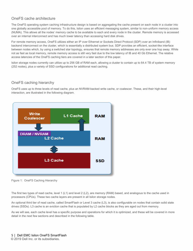
OneFS caching hierarchy OneFS uses up to three levels of read cache, plus an NVRAM-backed write cache, or coalescer. These, and their high-level interaction, are illustrated in the following diagram.
Figure 1: OneFS Caching Hierarchy
The first two types of read cache, level 1 (L1) and level 2 (L2), are memory (RAM) based, and analogous to the cache used in processors (CPUs). These two cache layers are present in all Isilon storage nodes.
An optional third tier of read cache, called SmartFlash or Level 3 cache (L3), is also configurable on nodes that contain solid state drives (SSDs). L3 cache is an eviction cache that is populated by L2 cache blocks as they are aged out from memory.
As we will see, each cache level has a specific purpose and operations for which it is optimized, and these will be covered in more detail in the next few sections and described in the following table.
6 |
Dell EMC Isilon OneFS SmartFlash © 2019 Dell Inc. or its subsidiaries.
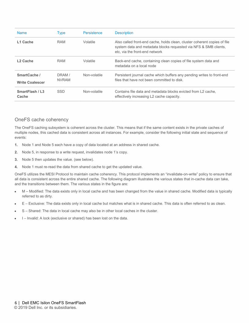
Name Type Persistence Description
L1 Cache RAM Volatile Also called front-end cache, holds clean, cluster coherent copies of file system data and metadata blocks requested via NFS & SMB clients, etc, via the front-end network
L2 Cache RAM Volatile Back-end cache, containing clean copies of file system data and metadata on a local node
SmartCache /
Write Coalescer
DRAM / NVRAM
Non-volatile Persistent journal cache which buffers any pending writes to front-end files that have not been committed to disk.
SmartFlash / L3 Cache
SSD Non-volatile Contains file data and metadata blocks evicted from L2 cache, effectively increasing L2 cache capacity.
OneFS cache coherency The OneFS caching subsystem is coherent across the cluster. This means that if the same content exists in the private caches of multiple nodes, this cached data is consistent across all instances. For example, consider the following initial state and sequence of events:
1. Node 1 and Node 5 each have a copy of data located at an address in shared cache.
2. Node 5, in response to a write request, invalidates node 1’s copy.
3. Node 5 then updates the value. (see below).
4. Node 1 must re-read the data from shared cache to get the updated value.
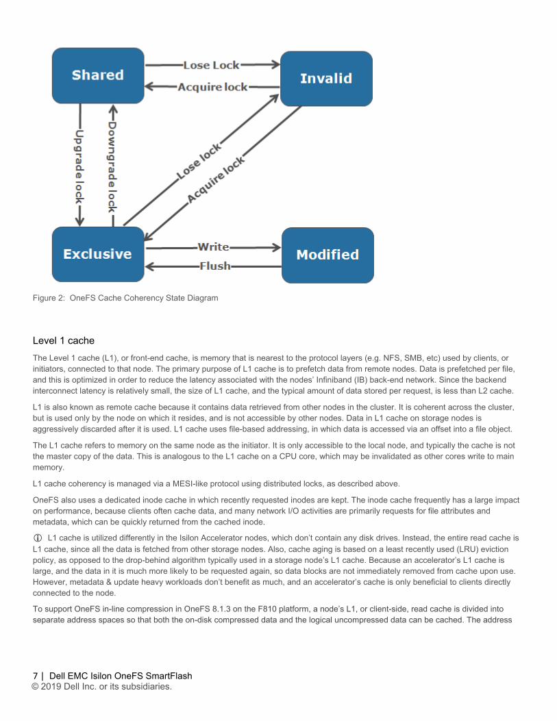
OneFS utilizes the MESI Protocol to maintain cache coherency. This protocol implements an “invalidate-on-write” policy to ensure that all data is consistent across the entire shared cache. The following diagram illustrates the various states that in-cache data can take, and the transitions between them. The various states in the figure are:
• M – Modified: The data exists only in local cache and has been changed from the value in shared cache. Modified data is typically referred to as dirty.
• E – Exclusive: The data exists only in local cache but matches what is in shared cache. This data is often referred to as clean.
• S – Shared: The data in local cache may also be in other local caches in the cluster.
• I – Invalid: A lock (exclusive or shared) has been lost on the data.
7 |
Dell EMC Isilon OneFS SmartFlash © 2019 Dell Inc. or its subsidiaries.
Figure 2: OneFS Cache Coherency State Diagram
Level 1 cache The Level 1 cache (L1), or front-end cache, is memory that is nearest to the protocol layers (e.g. NFS, SMB, etc) used by clients, or initiators, connected to that node. The primary purpose of L1 cache is to prefetch data from remote nodes. Data is prefetched per file, and this is optimized in order to reduce the latency associated with the nodes’ Infiniband (IB) back-end network. Since the backend interconnect latency is relatively small, the size of L1 cache, and the typical amount of data stored per request, is less than L2 cache.
L1 is also known as remote cache because it contains data retrieved from other nodes in the cluster. It is coherent across the cluster, but is used only by the node on which it resides, and is not accessible by other nodes. Data in L1 cache on storage nodes is aggressively discarded after it is used. L1 cache uses file-based addressing, in which data is accessed via an offset into a file object.
The L1 cache refers to memory on the same node as the initiator. It is only accessible to the local node, and typically the cache is not the master copy of the data. This is analogous to the L1 cache on a CPU core, which may be invalidated as other cores write to main memory.
L1 cache coherency is managed via a MESI-like protocol using distributed locks, as described above.
OneFS also uses a dedicated inode cache in which recently requested inodes are kept. The inode cache frequently has a large impact on performance, because clients often cache data, and many network I/O activities are primarily requests for file attributes and metadata, which can be quickly returned from the cached inode.
L1 cache is utilized differently in the Isilon Accelerator nodes, which don’t contain any disk drives. Instead, the entire read cache is L1 cache, since all the data is fetched from other storage nodes. Also, cache aging is based on a least recently used (LRU) eviction policy, as opposed to the drop-behind algorithm typically used in a storage node’s L1 cache. Because an accelerator’s L1 cache is large, and the data in it is much more likely to be requested again, so data blocks are not immediately removed from cache upon use. However, metadata & update heavy workloads don’t benefit as much, and an accelerator’s cache is only beneficial to clients directly connected to the node.
To support OneFS in-line compression in OneFS 8.1.3 on the F810 platform, a node’s L1, or client-side, read cache is divided into separate address spaces so that both the on-disk compressed data and the logical uncompressed data can be cached. The address
8 |
Dell EMC Isilon OneFS SmartFlash © 2019 Dell Inc. or its subsidiaries.
space for the L1 cache is already split for data and FEC blocks, so a similar technique is used to divide it again. Data in the uncompressed L1 cache is fed from data in the compressed L1 cache which, in turn, is fed from disk.
OneFS prefetch caching has also been enhanced to accommodate compressed data. Since reading part of a compressed chunk results in the entire compression chunk being cached, it will effectively mean that prefetch requests are rounded to compression chunk boundaries. Since a prefetch request is not complete until the uncompressed data is available in cache, the callback used for prefetch requests performs the decompression.
Level 2 cache The Level 2 cache (L2), or back-end cache, refers to local memory on the node on which a particular block of data is stored. L2 cache is globally accessible from any node in the cluster and is used to reduce the latency of a read operation by not requiring a seek directly from the disk drives. As such, the amount of data prefetched into L2 cache for use by remote nodes is much greater than that in L1 cache.
L2 cache is also known as local cache because it contains data retrieved from disk drives located on that node and then made available for requests from remote nodes. Data in L2 cache is evicted according to a Least Recently Used (LRU) algorithm.
Data in L2 cache is addressed by the local node using an offset into a disk drive which is local to that node. Since the node knows where the data requested by the remote nodes is located on disk, this is a very fast way of retrieving data destined for remote nodes. A remote node accesses L2 cache by doing a lookup of the block address for a particular file object. As described above, there is no MESI invalidation necessary here and the cache is updated automatically during writes and kept coherent by the transaction system and NVRAM.
Level 3 cache Also known as SmartFlash, level 3 cache (L3) refers to a subsystem which caches evicted L2 blocks on one or more SSDs on the node owning the L2 blocks. L3 cache is optional and requires SSD(s) to function. Unlike L1 and L2, not all nodes or clusters have an L3 cache, since it requires solid state drives (SSDs) to be present and exclusively reserved and configured for caching use.
L3 serves as a large, cost-effective method of extending of main memory per node from gigabytes to terabytes. This allows clients to retain a larger working set of data in cache, before being forced to retrieve data from spinning disk via a higher latency HDD operation. The L3 cache is populated with ‘interesting’ L2 blocks that are being dropped from memory as a result of L2’s least recently used cache eviction algorithm. Unlike RAM based caches, since L3 is based on persistent flash storage, once the cache is populated (warmed), it is highly durable and persists across node reboots, etc.
To be beneficial, L3 cache must provide performance gains in addition to the memory cost it imposes on L2. To achieve this, L3 uses a custom log-based filesystem with an index of cached blocks. The SSDs provide very good random read access characteristics, such that a hit in L3 cache is not that much slower than a hit in L2.
Testing has proven that a streaming write pattern is optimal for both reliable drive write performance, and to extend drive longevity. Both data and metadata blocks are written in a log pattern across the entire disk, wrapping around when the drive is full. These streaming writes assist the drive’s wear-leveling controller resulting in increased drive longevity.
To utilize multiple SSDs for cache effectively and automatically, L3 uses a consistent hashing approach to associate an L2 block address with one L3 SSD. In the event of an L3 drive failure, a portion of the cache will obviously disappear, but the remaining cache entries on other drives will still be valid. Before a new L3 drive may be added to the hash, some cache entries must be invalidated.
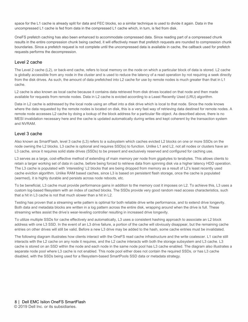
The following diagram illustrates how clients interact with the OneFS read cache infrastructure and the write coalescer. L1 cache still interacts with the L2 cache on any node it requires, and the L2 cache interacts with both the storage subsystem and L3 cache. L3 cache is stored on an SSD within the node and each node in the same node pool has L3 cache enabled. The diagram also illustrates a separate node pool where L3 cache is not enabled. This node pool either does not contain the required SSDs, or has L3 cache disabled, with the SSDs being used for a filesystem-based SmartPools SSD data or metadata strategy.
9 |
Dell EMC Isilon OneFS SmartFlash © 2019 Dell Inc. or its subsidiaries.
Figure 3: OneFS L1, L2 and L3 Caching Architecture
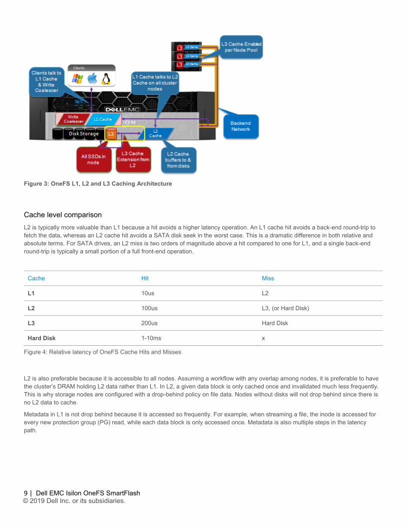
Cache level comparison L2 is typically more valuable than L1 because a hit avoids a higher latency operation. An L1 cache hit avoids a back-end round-trip to fetch the data, whereas an L2 cache hit avoids a SATA disk seek in the worst case. This is a dramatic difference in both relative and absolute terms. For SATA drives, an L2 miss is two orders of magnitude above a hit compared to one for L1, and a single back-end round-trip is typically a small portion of a full front-end operation.
Cache Hit Miss
L1 10us L2
L2 100us L3, (or Hard Disk)
L3 200us Hard Disk
Hard Disk 1-10ms x
Figure 4: Relative latency of OneFS Cache Hits and Misses
L2 is also preferable because it is accessible to all nodes. Assuming a workflow with any overlap among nodes, it is preferable to have the cluster’s DRAM holding L2 data rather than L1. In L2, a given data block is only cached once and invalidated much less frequently. This is why storage nodes are configured with a drop-behind policy on file data. Nodes without disks will not drop behind since there is no L2 data to cache.
Metadata in L1 is not drop behind because it is accessed so frequently. For example, when streaming a file, the inode is accessed for every new protection group (PG) read, while each data block is only accessed once. Metadata is also multiple steps in the latency path.
10 |
Dell EMC Isilon OneFS SmartFlash © 2019 Dell Inc. or its subsidiaries.
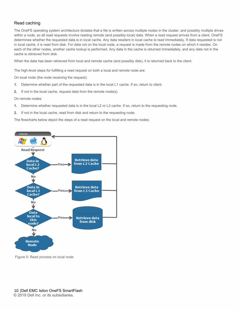
Read caching The OneFS operating system architecture dictates that a file is written across multiple nodes in the cluster, and possibly multiple drives within a node, so all read requests involve reading remote (and possibly local) data. When a read request arrives from a client, OneFS determines whether the requested data is in local cache. Any data resident in local cache is read immediately. If data requested is not in local cache, it is read from disk. For data not on the local node, a request is made from the remote nodes on which it resides. On each of the other nodes, another cache lookup is performed. Any data in the cache is returned immediately, and any data not in the cache is retrieved from disk.
When the data has been retrieved from local and remote cache (and possibly disk), it is returned back to the client. The high-level steps for fulfilling a read request on both a local and remote node are:
On local node (the node receiving the request):
1. Determine whether part of the requested data is in the local L1 cache. If so, return to client.
2. If not in the local cache, request data from the remote node(s).
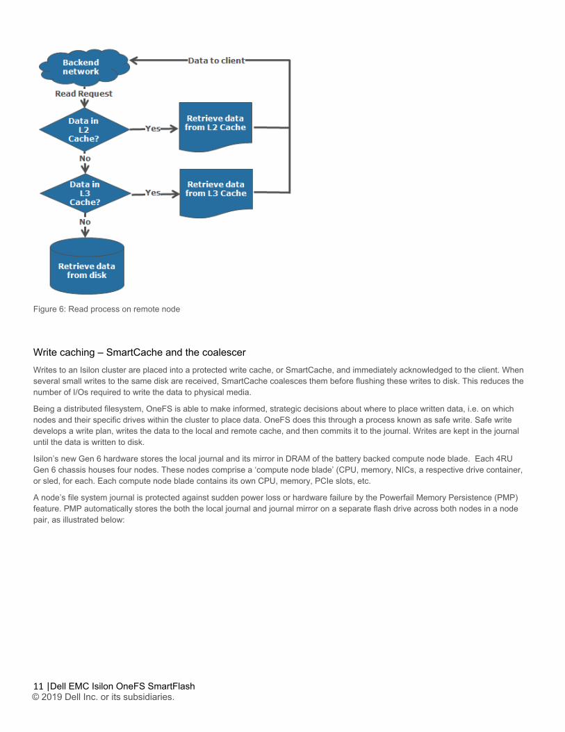
On remote nodes:
1. Determine whether requested data is in the local L2 or L3 cache. If so, return to the requesting node.
2. If not in the local cache, read from disk and return to the requesting node.
The flowcharts below depict the steps of a read request on the local and remote nodes:
Figure 5: Read process on local node
11 |
Dell EMC Isilon OneFS SmartFlash © 2019 Dell Inc. or its subsidiaries.
Figure 6: Read process on remote node
Write caching – SmartCache and the coalescer Writes to an Isilon cluster are placed into a protected write cache, or SmartCache, and immediately acknowledged to the client. When several small writes to the same disk are received, SmartCache coalesces them before flushing these writes to disk. This reduces the number of I/Os required to write the data to physical media.
Being a distributed filesystem, OneFS is able to make informed, strategic decisions about where to place written data, i.e. on which nodes and their specific drives within the cluster to place data. OneFS does this through a process known as safe write. Safe write develops a write plan, writes the data to the local and remote cache, and then commits it to the journal. Writes are kept in the journal until the data is written to disk.
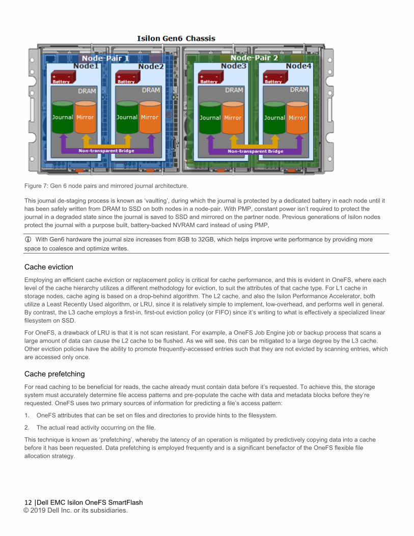
Isilon’s new Gen 6 hardware stores the local journal and its mirror in DRAM of the battery backed compute node blade. Each 4RU Gen 6 chassis houses four nodes. These nodes comprise a ‘compute node blade’ (CPU, memory, NICs, a respective drive container, or sled, for each. Each compute node blade contains its own CPU, memory, PCIe slots, etc.
A node’s file system journal is protected against sudden power loss or hardware failure by the Powerfail Memory Persistence (PMP) feature. PMP automatically stores the both the local journal and journal mirror on a separate flash drive across both nodes in a node pair, as illustrated below:
12 |
Dell EMC Isilon OneFS SmartFlash © 2019 Dell Inc. or its subsidiaries.
Figure 7: Gen 6 node pairs and mirrored journal architecture.
This journal de-staging process is known as ‘vaulting’, during which the journal is protected by a dedicated battery in each node until it has been safely written from DRAM to SSD on both nodes in a node-pair. With PMP, constant power isn’t required to protect the journal in a degraded state since the journal is saved to SSD and mirrored on the partner node. Previous generations of Isilon nodes protect the journal with a purpose built, battery-backed NVRAM card instead of using PMP,
With Gen6 hardware the journal size increases from 8GB to 32GB, which helps improve write performance by providing more space to coalesce and optimize writes.
Cache eviction Employing an efficient cache eviction or replacement policy is critical for cache performance, and this is evident in OneFS, where each level of the cache hierarchy utilizes a different methodology for eviction, to suit the attributes of that cache type. For L1 cache in storage nodes, cache aging is based on a drop-behind algorithm. The L2 cache, and also the Isilon Performance Accelerator, both utilize a Least Recently Used algorithm, or LRU, since it is relatively simple to implement, low-overhead, and performs well in general. By contrast, the L3 cache employs a first-in, first-out eviction policy (or FIFO) since it’s writing to what is effectively a specialized linear filesystem on SSD.
For OneFS, a drawback of LRU is that it is not scan resistant. For example, a OneFS Job Engine job or backup process that scans a large amount of data can cause the L2 cache to be flushed. As we will see, this can be mitigated to a large degree by the L3 cache. Other eviction policies have the ability to promote frequently-accessed entries such that they are not evicted by scanning entries, which are accessed only once.
Cache prefetching For read caching to be beneficial for reads, the cache already must contain data before it’s requested. To achieve this, the storage system must accurately determine file access patterns and pre-populate the cache with data and metadata blocks before they’re requested. OneFS uses two primary sources of information for predicting a file’s access pattern:
1. OneFS attributes that can be set on files and directories to provide hints to the filesystem.
2. The actual read activity occurring on the file.
This technique is known as ‘prefetching’, whereby the latency of an operation is mitigated by predictively copying data into a cache before it has been requested. Data prefetching is employed frequently and is a significant benefactor of the OneFS flexible file allocation strategy.
13 |
Dell EMC Isilon OneFS SmartFlash © 2019 Dell Inc. or its subsidiaries.
Flexible allocation involves determining the best layout for a file based on several factors, including cluster size (number of nodes), file size, and protection level (e.g.+2 or +3). The performance effect of flexible allocation is to place a file on the largest number of drives possible, given the above constraints.
The most straightforward application of prefetch is file data, where linear access is common for unstructured data, such as media files. Reading and writing of such files generally starts at the beginning and continues unimpeded to the end of the file. After a few requests, it becomes highly likely that a file is being streamed to the end.
OneFS data prefetch strategies can be configured either from the command line or via SmartPools. File data prefetch behavior can be controlled down to a per-file granularity using the isi set command’s access pattern setting. The available selectable file access patterns include concurrency (the default), streaming, and random.
Metadata prefetch occurs for the same reason as file data. Metadata scanning operations, such as finds and treewalks, can benefit. However, the use of metadata prefetch is less common because most accesses are random and unpredictable.
OneFS also provides a mechanism for prefetching files based on their nomenclature. In film and TV production, “streaming” often takes a different form as opposed to streaming an audio file. Each frame in a movie will often be contained in an individual file. As such, streaming reads a set of image files and prefetching across files is important. The files are often a subset of a directory, so directory entry prefetch does not apply. Ideally, this would be controlled by a client application, however in practice this rarely occurs.
To address this, OneFS has a file name prefetch facility. While file name prefetch is disabled by default, as with file data prefetch, it can be enabled with file access settings. When enabled, file name prefetch guesses the next sequence of files to be read by matching against several generic naming patterns.
Flexible file handle affinity (FHA) is a read-side algorithm designed to better utilize the internal threads used to read files. Using system configuration options and read access profiling, the number of operations per thread can be tuned to improve the efficiency of reads. FHA maps file handles to worker threads according to a combination of system settings, locality of the read requests (in terms of how close the requested addresses are), and the latency of the thread(s) serving requests to a particular client.
Prefetch does not directly apply to the L3 cache, since L3 is populated exclusively by blocks that are evicted from L2 cache. However, prefetch can affect L3 cache indirectly if/when prefetched blocks are evicted from L2 and are considered for inclusion in L3.
L3 cache persistence Caching is predicated on keeping hot data hot, so the most frequently accessed data and metadata on a node should just remain in L2 cache and not get evicted to L3. For the next tier of cached data that’s accessed frequently enough to live in L3, but not frequently enough to always live in RAM, there’s a mechanism in place to keep these semi-frequently accessed blocks in L3.
To maintain this L3 cache persistence, when the kernel goes to read a metadata or data block, the following steps are performed:
1. First, L1 cache is checked. Then, if no hit, L2 cache is consulted.
2. If a hit is found in memory, it’s done.
3. If not in memory, L3 is then checked.
4. If there’s an L3 hit, and that item is near the end of the L3 FIFO (last 10%), a flag is set on the block which causes it to be evicted into L3 again when it is evicted out of L2.
This marking process helps guard against the chronological eviction of blocks that are accessed while they are in the last 10% of the cache and serves to keep most of the useful data in cache.
Benefits of using SSDs for L3 cache There are several benefits to using SSDs for caching rather than as traditional file system storage devices. For example, when reserved for caching, the entire SSD will be used, and writes will occur in a very linear and predictable way. This provides far better utilization and also results in considerably reduced wear and increased durability over regular file system usage, particularly with random write workloads. Using SSD for cache also makes sizing SSD capacity a much more straightforward and less error prone prospect and requires considerably less management overhead as compared with configuring certain portions of a dataset to use SSDs as a storage tier within the filesystem.
14 |
Dell EMC Isilon OneFS SmartFlash © 2019 Dell Inc. or its subsidiaries.
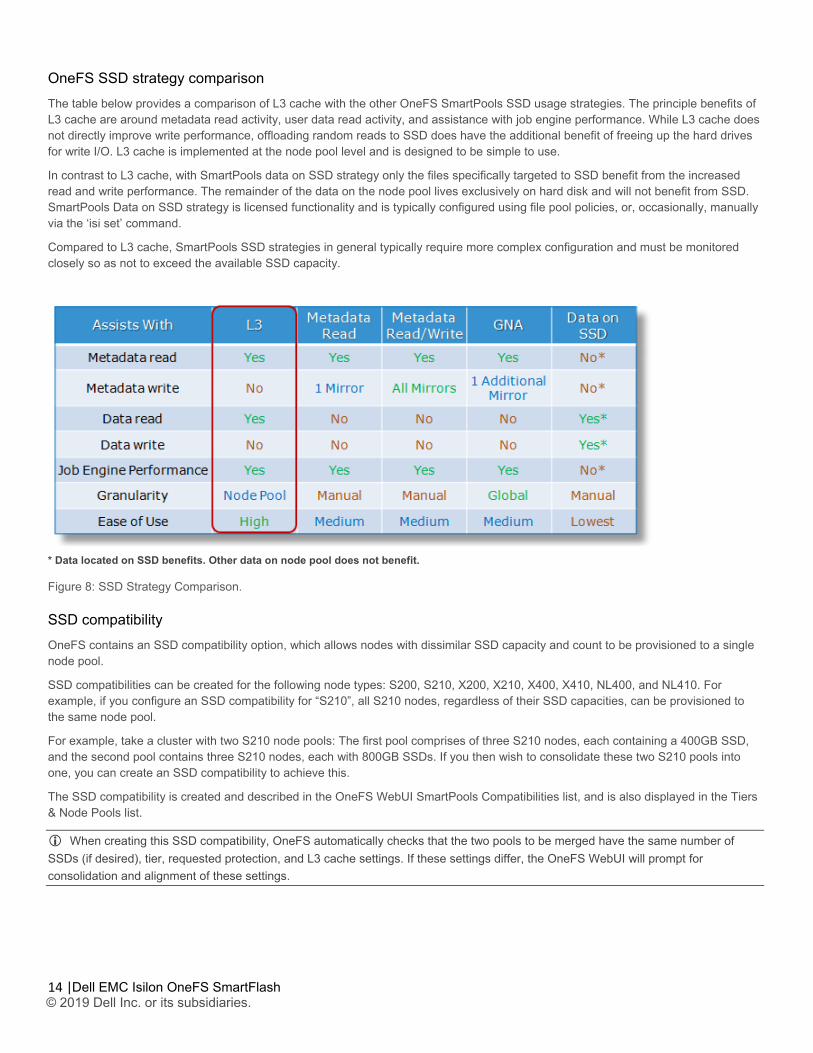
OneFS SSD strategy comparison The table below provides a comparison of L3 cache with the other OneFS SmartPools SSD usage strategies. The principle benefits of L3 cache are around metadata read activity, user data read activity, and assistance with job engine performance. While L3 cache does not directly improve write performance, offloading random reads to SSD does have the additional benefit of freeing up the hard drives for write I/O. L3 cache is implemented at the node pool level and is designed to be simple to use.
In contrast to L3 cache, with SmartPools data on SSD strategy only the files specifically targeted to SSD benefit from the increased read and write performance. The remainder of the data on the node pool lives exclusively on hard disk and will not benefit from SSD. SmartPools Data on SSD strategy is licensed functionality and is typically configured using file pool policies, or, occasionally, manually via the ‘isi set’ command.
Compared to L3 cache, SmartPools SSD strategies in general typically require more complex configuration and must be monitored closely so as not to exceed the available SSD capacity.
* Data located on SSD benefits. Other data on node pool does not benefit.
Figure 8: SSD Strategy Comparison.
SSD compatibility OneFS contains an SSD compatibility option, which allows nodes with dissimilar SSD capacity and count to be provisioned to a single node pool.
SSD compatibilities can be created for the following node types: S200, S210, X200, X210, X400, X410, NL400, and NL410. For example, if you configure an SSD compatibility for “S210”, all S210 nodes, regardless of their SSD capacities, can be provisioned to the same node pool.
For example, take a cluster with two S210 node pools: The first pool comprises of three S210 nodes, each containing a 400GB SSD, and the second pool contains three S210 nodes, each with 800GB SSDs. If you then wish to consolidate these two S210 pools into one, you can create an SSD compatibility to achieve this.
The SSD compatibility is created and described in the OneFS WebUI SmartPools Compatibilities list, and is also displayed in the Tiers & Node Pools list.
When creating this SSD compatibility, OneFS automatically checks that the two pools to be merged have the same number of SSDs (if desired), tier, requested protection, and L3 cache settings. If these settings differ, the OneFS WebUI will prompt for consolidation and alignment of these settings.
15 |
Dell EMC Isilon OneFS SmartFlash © 2019 Dell Inc. or its subsidiaries.
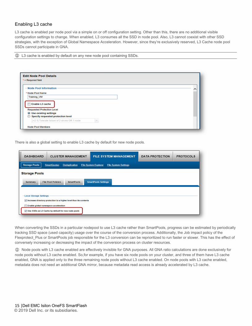
Enabling L3 cache L3 cache is enabled per node pool via a simple on or off configuration setting. Other than this, there are no additional visible configuration settings to change. When enabled, L3 consumes all the SSD in node pool. Also, L3 cannot coexist with other SSD strategies, with the exception of Global Namespace Acceleration. However, since they’re exclusively reserved, L3 Cache node pool SSDs cannot participate in GNA.
L3 cache is enabled by default on any new node pool containing SSDs.
There is also a global setting to enable L3 cache by default for new node pools.
When converting the SSDs in a particular nodepool to use L3 cache rather than SmartPools, progress can be estimated by periodically tracking SSD space (used capacity) usage over the course of the conversion process. Additionally, the Job impact policy of the Flexprotect_Plus or SmartPools job responsible for the L3 conversion can be reprioritized to run faster or slower. This has the effect of conversely increasing or decreasing the impact of the conversion process on cluster resources.
Node pools with L3 cache enabled are effectively invisible for GNA purposes. All GNA ratio calculations are done exclusively for node pools without L3 cache enabled. So,for example, if you have six node pools on your cluster, and three of them have L3 cache enabled, GNA is applied only to the three remaining node pools without L3 cache enabled. On node pools with L3 cache enabled, metadata does not need an additional GNA mirror, because metadata read access is already accelerated by L3 cache.
16 |
Dell EMC Isilon OneFS SmartFlash © 2019 Dell Inc. or its subsidiaries.
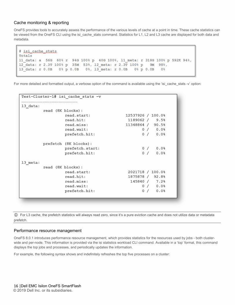
Cache monitoring & reporting OneFS provides tools to accurately assess the performance of the various levels of cache at a point in time. These cache statistics can be viewed from the OneFS CLI using the isi_cache_stats command. Statistics for L1, L2 and L3 cache are displayed for both data and metadata.
For more detailed and formatted output, a verbose option of the command is available using the ‘isi_cache_stats -v’ option:
For L3 cache, the prefetch statistics will always read zero, since it’s a pure eviction cache and does not utilize data or metadata prefetch.
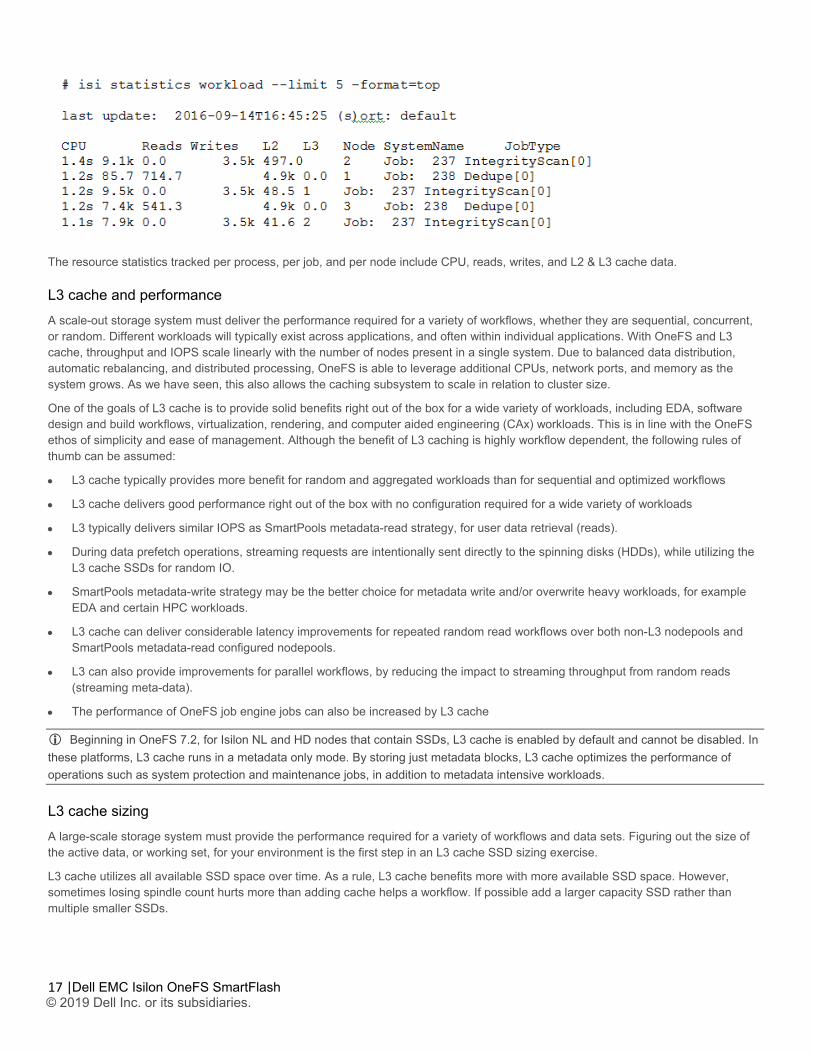
Performance resource management OneFS 8.0.1 introduces performance resource management, which provides statistics for the resources used by jobs - both cluster-wide and per-node. This information is provided via the isi statistics workload CLI command. Available in a ‘top’ format, this command displays the top jobs and processes, and periodically updates the information.
For example, the following syntax shows and indefinitely refreshes the top five processes on a cluster:
17 |
Dell EMC Isilon OneFS SmartFlash © 2019 Dell Inc. or its subsidiaries.
The resource statistics tracked per process, per job, and per node include CPU, reads, writes, and L2 & L3 cache data.
L3 cache and performance A scale-out storage system must deliver the performance required for a variety of workflows, whether they are sequential, concurrent, or random. Different workloads will typically exist across applications, and often within individual applications. With OneFS and L3 cache, throughput and IOPS scale linearly with the number of nodes present in a single system. Due to balanced data distribution, automatic rebalancing, and distributed processing, OneFS is able to leverage additional CPUs, network ports, and memory as the system grows. As we have seen, this also allows the caching subsystem to scale in relation to cluster size.
One of the goals of L3 cache is to provide solid benefits right out of the box for a wide variety of workloads, including EDA, software design and build workflows, virtualization, rendering, and computer aided engineering (CAx) workloads. This is in line with the OneFS ethos of simplicity and ease of management. Although the benefit of L3 caching is highly workflow dependent, the following rules of thumb can be assumed:
• L3 cache typically provides more benefit for random and aggregated workloads than for sequential and optimized workflows
• L3 cache delivers good performance right out of the box with no configuration required for a wide variety of workloads
• L3 typically delivers similar IOPS as SmartPools metadata-read strategy, for user data retrieval (reads).
• During data prefetch operations, streaming requests are intentionally sent directly to the spinning disks (HDDs), while utilizing the L3 cache SSDs for random IO.
• SmartPools metadata-write strategy may be the better choice for metadata write and/or overwrite heavy workloads, for example EDA and certain HPC workloads.
• L3 cache can deliver considerable latency improvements for repeated random read workflows over both non-L3 nodepools and SmartPools metadata-read configured nodepools.
• L3 can also provide improvements for parallel workflows, by reducing the impact to streaming throughput from random reads (streaming meta-data).
• The performance of OneFS job engine jobs can also be increased by L3 cache
Beginning in OneFS 7.2, for Isilon NL and HD nodes that contain SSDs, L3 cache is enabled by default and cannot be disabled. In these platforms, L3 cache runs in a metadata only mode. By storing just metadata blocks, L3 cache optimizes the performance of operations such as system protection and maintenance jobs, in addition to metadata intensive workloads.
L3 cache sizing A large-scale storage system must provide the performance required for a variety of workflows and data sets. Figuring out the size of the active data, or working set, for your environment is the first step in an L3 cache SSD sizing exercise.
L3 cache utilizes all available SSD space over time. As a rule, L3 cache benefits more with more available SSD space. However, sometimes losing spindle count hurts more than adding cache helps a workflow. If possible add a larger capacity SSD rather than multiple smaller SSDs.
18 |
Dell EMC Isilon OneFS SmartFlash © 2019 Dell Inc. or its subsidiaries.
An L3 cache sizing exercise involves calculating the correct amount of SSD space to fit the working data set. This can be done by using the isi_cache_stats command to periodically capture L2 cache statistics on an existing cluster.
Run the following commands based on the workload activity cycle, at job start and job end. Initially run isi_cache_stats –c in order to reset, or zero out, the counters. Then run isi_cache_stats –v at workload activity completion and save the output. This will help determine an accurate indication of the size of the working data set, by looking at the L2 cache miss rates for both data and metadata on a single node.
These cache miss counters are displayed as 8KB blocks. As such, an L2_data_read.miss value of 1024 blocks represents 8 MB of actual missed data.
The formula for calculating the working set size is:
(L2_data_read.miss + L2_meta_read.miss) = working_set size
Once the working set size has been calculated, a good rule of thumb is to size L3 SSD capacity per node according to the following formula:
L2 capacity + L3 capacity >= 150% of working set size.
There are diminishing returns for L3 cache after a certain point. With too high an SSD-to-working-set size ratio, the cache hits decrease and fail to add greater benefit. Conversely, when compared to SmartPools SSD strategies, another benefit of using SSDs for L3 cache is that performance will degrade much more gracefully if metadata does happen to exceed the SSD capacity available.
L3 cache is not applicable for nodes containing 16 or more SSDs.
L3 cache and Global Namespace Acceleration Global Name Space Acceleration, or GNA, is a configurable component of the OneFS SmartPools data tiering product. GNA’s goal is to help accelerate metadata read operations (filename lookup, access, etc.) by keeping a copy of the metadata for the entire cluster on high performance, low latency SSD media. This allows customers to increase the performance of certain workflows across the whole file system without having to upgrade/purchase SSDs for every node in the cluster. To achieve this, a mirror of all the metadata from storage pools that do not contain SSDs is stored on any SSDs available. As such, metadata read operations are accelerated even for data on node pools that have no SSDs.
To implement L3 cache and GNA in the same cluster you must create path-based file pool policies that target an L3 cache enabled node pool. The data SSD strategy and snapshot SSD strategy for this L3 cache enabled node pole should be set to ‘avoid SSD’. This allows the L3 cache nodepool to reference metadata blocks in its L3 cache, rather than defaulting to using the GNA metadata mirror on another pool which would incur a latency hit. OneFS SmartPools must be licensed in order to configure filepool policies, and these can be added using the following command:
# isi filepool policies create <policy-name> --begin-filter --path <path> --end-filter --data-storage-target <L3-cache-node-pool-ID> --data-ssd-strategy avoid --snapshot-ssd-strategy avoid --apply-order 1
This file pool policy should occur at the top of the policy order, as specified by the ‘apply-order’ flag with value ‘1’ in the command example above.
To prevent capacity or performance oversubscription of a cluster’s SSD resources, there are several requirements that need to be satisfied in order to activate GNA on a mixed node cluster running L3 cache:
• At least 20% of the non-L3 cache nodes in the cluster must contain SSDs.
• A minimum of 2% of the cluster usable capacity that’s not residing on L3 cache enabled nodes must be on SSD in order to enable GNA.
• General SmartPools configuration requirements apply including:
19 |
Dell EMC Isilon OneFS SmartFlash © 2019 Dell Inc. or its subsidiaries.
• A minimum of three nodes per node pool
• All nodes within a node pool must have the same configuration
• All-SSD nodes (nodes with only SSD Drives in them) need to follow the same rules – three nodes to form a node pool.
Assuming the above requirements are met, GNA can be enabled across the entire cluster via the OneFS SmartPools WebUI. This can be found by navigating under File System Management -> SmartPools -> Settings
For workloads with a primary performance tier, and an archive element without SSD, L3 cache and GNA can be run in concert within the same cluster.
For example, say you have a cluster comprising four H600 nodes, four H400 nodes, and three NL400 nodes.
The SSDs in the H600 tier can be enabled to run L3 cache. In so doing, these SSDs will be reformatted and won’t be available for regular file system activity.
The H400 nodes can be used to run GNA (assuming they meet the 2%/20% rules above) and hold a read-only mirror of both its and the NL400 nodes’ metadata. This means that even the NL400 nodes, that have no SSD, can benefit from fast metadata lookups for a single mirror.
In the instances where all the nodes in the cluster contain SSD, L3 caching is intended as a replacement for GNA.
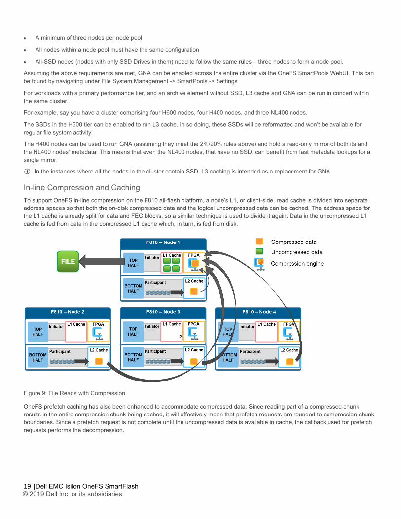
In-line Compression and Caching To support OneFS in-line compression on the F810 all-flash platform, a node’s L1, or client-side, read cache is divided into separate address spaces so that both the on-disk compressed data and the logical uncompressed data can be cached. The address space for the L1 cache is already split for data and FEC blocks, so a similar technique is used to divide it again. Data in the uncompressed L1 cache is fed from data in the compressed L1 cache which, in turn, is fed from disk.
Figure 9: File Reads with Compression
OneFS prefetch caching has also been enhanced to accommodate compressed data. Since reading part of a compressed chunk results in the entire compression chunk being cached, it will effectively mean that prefetch requests are rounded to compression chunk boundaries. Since a prefetch request is not complete until the uncompressed data is available in cache, the callback used for prefetch requests performs the decompression.
20 |
Dell EMC Isilon OneFS SmartFlash © 2019 Dell Inc. or its subsidiaries.
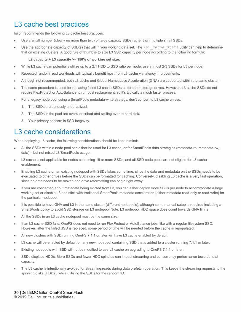
L3 cache best practices Isilon recommends the following L3 cache best practices:
• Use a small number (ideally no more than two) of large capacity SSDs rather than multiple small SSDs.
• Use the appropriate capacity of SSD(s) that will fit your working data set. The isi_cache_stats utility can help to determine that on existing clusters. A good rule of thumb is to size L3 SSD capacity per node according to the following formula:
L2 capacity + L3 capacity >= 150% of working set size.
• While L3 cache can potentially utilize up to a 2:1 HDD to SSD ratio per node, use at most 2-3 SSDs for L3 per node.
• Repeated random read workloads will typically benefit most from L3 cache via latency improvements.
• Although not recommended, both L3 cache and Global Namespace Acceleration (GNA) are supported within the same cluster.
• The same procedure is used for replacing failed L3 cache SSDs as for other storage drives. However, L3 cache SSDs do not require FlexProtect or AutoBalance to run post replacement, so it’s typically a much faster process.
• For a legacy node pool using a SmartPools metadata-write strategy, don’t convert to L3 cache unless:
1. The SSDs are seriously underutilized.
2. The SSDs in the pool are oversubscribed and spilling over to hard disk.
3. Your primary concern is SSD longevity.
L3 cache considerations When deploying L3 cache, the following considerations should be kept in mind:
• All the SSDs within a node pool can either be used for L3 cache, or for SmartPools data strategies (metadata-ro, metadata-rw, data) – but not mixed L3/SmartPools usage.
• L3 cache is not applicable for nodes containing 16 or more SSDs, and all SSD node pools are not eligible for L3 cache enablement.
• Enabling L3 cache on an existing nodepool with SSDs takes some time, since the data and metadata on the SSDs needs to be evacuated to other drives before the SSDs can be formatted for caching. Conversely, disabling L3 cache is a very fast operation, since no data needs to be moved and drive reformatting can begin right away.
• If you are concerned about metadata being evicted from L3, you can either deploy more SSDs per node to accommodate a large working set or disable L3 and stick with traditional SmartPools metadata acceleration (either metadata read-only or read-write) for the particular nodepool.
• It is possible to have GNA and L3 in the same cluster (different nodepools), although some manual setup is required including a SmartPools policy to avoid SSD storage on L3 nodepool Note: L3 nodepool HDD space does count towards GNA limits
• All the SSDs in an L3 cache nodepool must be the same size.
• If an L3 cache SSD fails, OneFS does not need to run FlexProtect or AutoBalance jobs, like with a regular filesystem SSD. However, after the failed SSD is replaced, some period of time will be needed before the cache is repopulated.
• All new clusters with SSD running OneFS 7.1.1 or later will have L3 cache enabled by default.
• L3 cache will be enabled by default on any new nodepool containing SSD that’s added to a cluster running 7.1.1 or later.
• Existing nodepools with SSD will not be modified to use L3 cache on upgrading to OneFS 7.1.1 or later.
• SSDs displace HDDs. More SSDs and fewer HDD spindles can impact streaming and concurrency performance towards total capacity.
• The L3 cache is intentionally avoided for streaming reads during data prefetch operation. This keeps the streaming requests to the spinning disks (HDDs), while utilizing the SSDs for the random IO.
21 |
Dell EMC Isilon OneFS SmartFlash © 2019 Dell Inc. or its subsidiaries.
• From OneFS 7.2.1 onwards, L3 cache nodepool hard drive space DOES NOT count in GNA SSD percentage calculations.
• For OneFS 7.2 and prior releases, L3 cache nodepool hard drive space DOES count in GNA SSD percentage calculations.
• In L3 cache, metadata is preferentially cached over data blocks.
• When a node reboots, there’s no automatic flushing of L2 blocks to L3 cache.
• Unlike HDDs and SSDs that are used for storage, when an SSD used for L3 cache fails, the drive state should immediately change to ‘REPLACE’ without a FlexProtect job running. An SSD drive used for L3 cache contains only cache data that does not have to be protected by FlexProtect. After the drive state changes to REPLACE, you can pull and replace the failed SSD.
• Although there’s no percentage completion reporting shown when converting nodepools to use L3 cache, this can be estimated by tracking SSD space usage throughout the job run. The Job impact policy of the Flexprotect_Plus or SmartPools job, responsible for the L3 conversion, can also be reprioritized to run faster or slower.
• Current and historical L3 cache statistics are reported by InsightIQ.
• For L3 cache, the isi_cache_stats prefetch statistics will always read zero, since it’s purely an eviction cache and does not utilize data or metadata prefetch.
• L3 cache has a metadata only mode (as opposed to data and metadata) to support Isilon’s archive series storage nodes.
Conclusion Caching of data and metadata is widely used to increase the performance of storage systems by keeping the most frequently accessed content in memory. Isilon’s caching architecture goes beyond the common approach by providing a scale-out caching infrastructure, leveraging both the speed of system memory and the persistence and affordability of SSDs and NVRAM. OneFS caching provides faster access to content by intelligently predicting how content will be accessed and retrieving just the parts of files that are required. This technology enables Isilon to deliver unparalleled storage performance, while maintaining globally coherent read and write access across the entire Isilon cluster.
The OneFS operating system, featuring a fully distributed file system and a multi-tier, globally coherent cache, gives businesses facing a deluge of unstructured data extreme levels of total aggregate throughput – accelerating access to critical data while dramatically reducing the cost and complexity of storing and managing it.
Scalability, performance, ease of management, data protection, security and interoperability are critical in a storage system that can meet user needs and the ongoing challenges of the data center – especially in today’s world of “Big Data” in the enterprise.
With OneFS, Isilon storage systems are simple to install, manage and scale, at virtually any size -- organizations and administrators can scale from as little as 18 TB to greater than 68 PB within a single file system, single volume, with a single point of administration. OneFS delivers high levels of performance, throughput, and capacity, without adding management complexity.
© 2019 Dell Inc. or its subsidiaries. All Rights Reserved. Dell, EMC and other trademarks are trademarks of Dell Inc. or its subsidiaries. Other trademarks may be trademarks of their respective owners. Reference Number: H13249.4
Learn more about Dell EMC Isilon Solutions
Contact a Dell EMC Expert View more resources Join the conversation with #DellEMCStorage
Recommended