PrefaceThank you for purchasing the D-51 pH meter .This meter is designed with a compact body that can be held in one hand and features a water-resistant construction Note 1. It has a large-sized LCD display, which enables to use the varied functions by simple operations, and especially will be convenient to use on-location.Carefully read this manual before using the meter.
Note 1: The water-resistant construction of this meter conforms to IP-67 of IEC 529, entitled “Water resistant testing and protection against penetration by solid matter for electrical machinery and equipment.” To maintain the water-resistant construction of this meter, follow the instructions in this manual when using the meter.IP-67 standards
・ Dust does not get into internal parts.・Water does not flow into internal parts when the meter is submerged 1 m below the surface of the water for 30 minutes, at a temperature differential between the water and the device of 5 or less.
HORIBA's Warranty and ResponsibilityYour meter is covered by HORIBA's warranty for a period of one (1) year, under normal use. Although unlikely, if any trouble attributable to HORIBA should occur during this period, necessary exchange or repairs shall be conducted by HORIBA, free of charge. The warranty does not cover the following:
・ Any trouble or damage attributable to actions or conditions specifically mentioned to be avoided in the operation manuals ・ Any trouble or damage attributable to use of the meter in ways or for purposes other than those described in the operation manuals・ If any repairs renovations, disassembly, etc. are performed on this meter by any party other than HORIBA or a party authorized by HORIBA・ Any alteration to the external appearance of this pH meter attributable to scratches, dirt, etc. occurring through normal use・Wear and tear to parts, the exchange of accessories, or the use of any parts not specified by HORIBA
HORIBA also shall not be liable for any damages resulting from any malfunctions of this product, any erasure of data, or any other uses of this product.
Unauthorized reprinting or copying of this operation manualNo unauthorized reprinting or copying of all or part of this operation manual is allowed. The utmost care has been used in the preparation of this operation manual. If, however, you have any questions or notice any errors, please contact the HORIBA customer service center printed on the back cover of this operation manual.
Copyright © HORIBA, Ltd. 2003
Precautions for use
I
CE MarkingThis product is in conformity with the following directives and standards:
Directives:The EMC Directives 89/336/EEC The Electrical Product Safety Directive 73/23/EEC
Standards: EN61326: 1997+A1:1998 (EMISSION: Class B, IMMUNITY Category: Minimum Require- ment)EN61010-1: 2001
Installation Environment
This product is designed for the following environment.- Pollution degree 2- Measurement category Ⅰ
WARNING:Do Not use the equipment for measurements within measurement categories Ⅱ , Ⅲ and Ⅳ .
FCC WarningThis equipment has been tested and found to comply withthe limits for a Class A digital device, pursuant to part 15 of the FCC Rules.These limits are designed to provide reasonable protection against harmful interference when the equipment is operated in a commercial environment.This equipment generates, uses, and can radiate radio frequency energy and, if not installed and used in accordance with the instruction manual, may cause harmful interference to radio communications. Operation of this equipment in a residential area is likely to cause harmful interference in which case the user will be required to correct the interference at his own expense.

Precautions for use
II
Type and Definition of Signal WordsFor the safety use, the meter is equipped with the Warning Labels to alert every operator and user to the possible risk and danger. Before using understanding each message.The meaning of signal words are as follows:
Safety PrecautionsFor the safety use, be sure to read the following precautions:
WARNING:Do not use any unspecified AC adapters. Heat or fire may occur to cause fire or accidents.
Do not disassemble or modify the meter. Heat or fire may occur to cause fire or accidents.
CAUTION:Do not use the serial communication or AC adapter in the place that may possibly contact with moisture. It may cause fire, electric shock, or breakage.
Part of the electrode is made of glass; handle with care not to break it.
(WARNING) This indicates an potentially hazardous situation which, if not avoided, will result in death or serious injury.
(CAUTION) This indicates a potentially hazardous situation which, if not avoided, may result in minor or moderate injury. It may also be used to alert unsafe practices.
Precautions for use
III
Indication
WARNINGThis indicates an potentially hazardous situation which, if not avoided, will result in death or serious injury.
CAUTIONThis indicates a potentially hazardous situation which, if not avoided, may result in minor or moderate injury. It may also be used to alert unsafe practices.
This mark indicates the operation requires a special care and attention.
This mark indicates to which the reader should go for reference.
This mark indicates reference information. HINT!
Precautions for use
IV
Cautionary Items Precautions
Do not give physical shock to the meter like dropping or hitting.Do not immerse the meter into alcohol, organic solvent, strong acid, strong alkaline, and other similar solutions. The meter contains ABS resin, acrylic resin, and various rubber products in its body.
Do not use a hair-dryer for drying the meter. When the meter is dropped into water or get wet, wipe it using soft cloth.
Perform the key operation by the fingers, not by the hard object like metal stick or rod.
Be careful not to let water into the meter when the electrode connector is empty or the AC adapter or serial communications cable has been connected. In those states, the meter is not water-proof.
To disconnect the electrode cable or interface cable, pull them out with holding the connector part. Do not pull the cable part; it may cause a breakage.
Do not remove the battery gasket or twist it.When opening the battery case, make sure that no foreign matter is attached to the battery gasket.
Do not use any unspecified batteries ; it may cause a breakage.
Location of use and storageThe place which room temperature is at 0 to 45
The place which relative humidity is under 80% and free from condensation
Do not use or store the meter at;The place of much dustThe place with strong vibrationThe place with direct sunlight The place with corrosive gas generation The place near from an air-conditioner The place with direct wind
Move and Transportation of the meterTo transport the meter, use the packaging box at the delivery. Transportation by any unspecified packing methods may cause a breakage.
DisposalStandard solution used for the calibration must be under neutralization before the disposal. As for the disposal of the meter, treat it as an industrial waste.
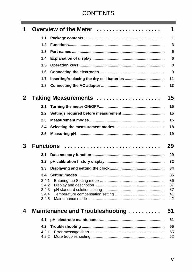
CONTENTS
V
1 Overview of the Meter . . . . . . . . . . . . . . . . . . . . 11.1 Package contents ........................................................................... 11.2 Functions......................................................................................... 31.3 Part names ...................................................................................... 51.4 Explanation of display.................................................................... 61.5 Operation keys................................................................................ 81.6 Connecting the electrodes............................................................. 91.7 Inserting/replacing the dry-cell batteries ..................................... 111.8 Connecting the AC adapter ........................................................... 13
2 Taking Measurements . . . . . . . . . . . . . . . . . . . . 152.1 Turning the meter ON/OFF............................................................. 152.2 Settings required before measurement........................................ 152.3 Measurement modes...................................................................... 162.4 Selecting the measurement modes .............................................. 182.5 Measuring pH.................................................................................. 19
3 Functions . . . . . . . . . . . . . . . . . . . . . . . . . . . . . . 293.1 Data memory function.................................................................... 293.2 pH calibration history display ....................................................... 323.3 Displaying and setting the clock................................................... 343.4 Setting modes ................................................................................. 363.4.1 Entering the Setting mode ............................................................ 363.4.2 Display and description ................................................................ 373.4.3 pH standard solution setting ......................................................... 373.4.4 Temperature compensation setting .............................................. 413.4.5 Maintenance mode ....................................................................... 42
4 Maintenance and Troubleshooting . . . . . . . . . . 514.1 pH electrode maintenance ............................................................ 514.2 Troubleshooting ............................................................................. 554.2.1 Error message chart ..................................................................... 554.2.2 More troubleshooting .................................................................... 62

CONTENTS
VI HORIBA
5 Reference . . . . . . . . . . . . . . . . . . . . . . . . . . . . . . 695.1 pH measurement............................................................................. 705.2 Specifications ................................................................................. 765.3 Default settings............................................................................... 775.4 Operation flowcharts...................................................................... 785.5 Spare and optional parts.............................................................. 795.5.1 Spare parts list ........................................................................... 795.5.2 Options ......................................................................................... 81
1 Overview of the Meter 1.1 Package contents
D-51 1
1 Overview of the Meter
This chapter explains the part names, how to connect the electrodes, how to replace the batteries, and precautions when using the meter.
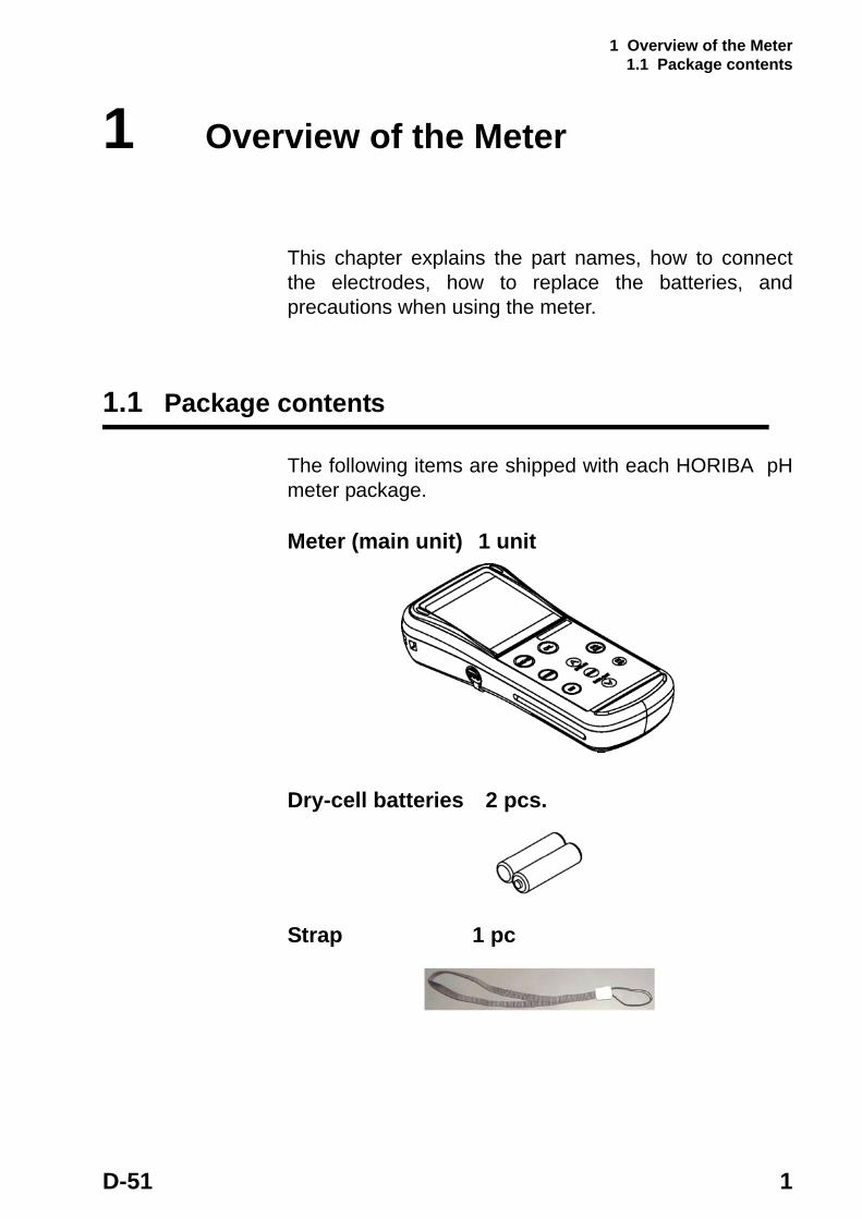
1.1 Package contents
The following items are shipped with each HORIBA pH meter package.
Meter (main unit) 1 unit
Dry-cell batteries 2 pcs.
Strap 1 pc

1 Overview of the Meter 1.1 Package contents
2 HORIBA
Soft case 1 pc
Operation manual 1 book
To take measurements, you will need electrode(s). Refer to “5.5 Spare and optional parts” page 79 when purchasing the electrode(s).
1 Overview of the Meter 1.2 Functions
D-51 3
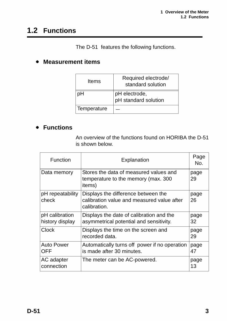
1.2 Functions
The D-51 features the following functions.
Measurement items
FunctionsAn overview of the functions found on HORIBA the D-51 is shown below.
Items Required electrode/standard solution
pH pH electrode,pH standard solution
Temperature -
Function Explanation Page No.
Data memory Stores the data of measured values and temperature to the memory (max. 300 items)
page 29
pH repeatability check
Displays the difference between the calibration value and measured value after calibration.
page 26
pH calibration history display
Displays the date of calibration and the asymmetrical potential and sensitivity.
page 32
Clock Displays the time on the screen and recorded data.
page 29
Auto Power OFF
Automatically turns off power if no operation is made after 30 minutes.
page 47
AC adapter connection
The meter can be AC-powered. page 13

1 Overview of the Meter 1.2 Functions
4 HORIBA
Setting Items
Functions in Maintenance mode
Function Explanation Page No.
pH standard solution setting
Enables standard solution used for calibration to be changed to NIST and US specifications settings.
page 37
Temperature compensation
Toggles between Automatic Temperature Compensation (ATC) mode that measures the sample temperature using the temperature sensor built-in the electrode and Manual Temperature Compensation (MTC) mode that uses user-specified temperature.
page 41
Function Explanation Page No.
LCD check Enables check for whether or not all LCD segments are displayed.
page 44
Battery voltage check
Enables simple check of battery voltage. page 45
Temperature display calibration
Adjusts the display of the temperature sensor to the actual temperature.
page 46
Auto Power OFF Sets the function that automatically turns the power OFF if no keys are touched 30 minutes.
page 47
Remaining data memory
Displays the remaining memory. page 48
Data memory clear
Deletes data in memory. page 48
Initializing settings
Initializes all settings to the default values. page 49
1 Overview of the Meter 1.3 Part names
D-51 5
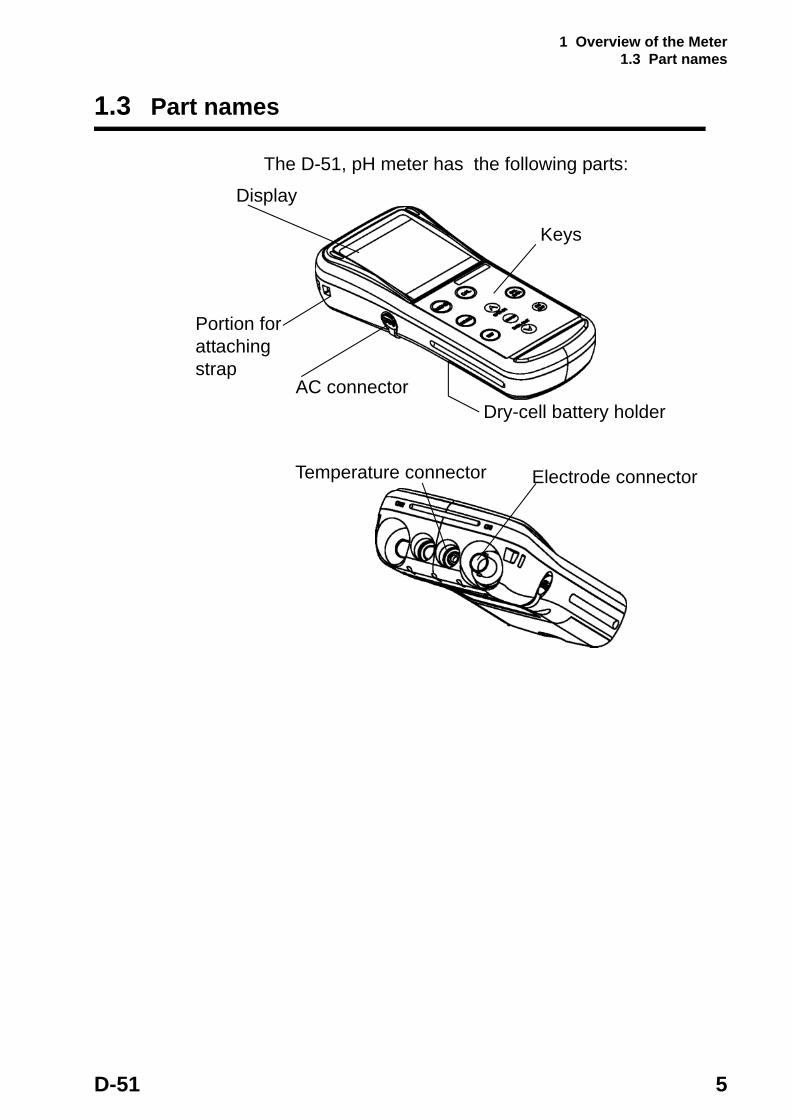
1.3 Part names
The D-51, pH meter has the following parts:
Portion for attaching strap
Dry-cell battery holder
Display
AC connector
Keys
Electrode connectorTemperature connector
1 Overview of the Meter 1.4 Explanation of display
6 HORIBA
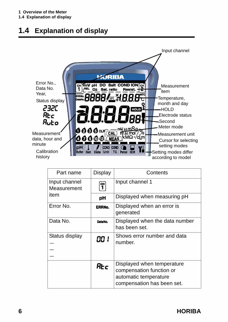
1.4 Explanation of display
Error No., Data No. Year,
Input channel
Temperature, month and day
Measurement item
Calibration history
Status display
SecondMeter modeMeasurement unitCursor for selecting setting modes
Measurement data, hour and minute
HOLD
Setting modes differ according to model
Electrode status
Part name Display Contents
Input channelMeasurement item
Input channel 1
Displayed when measuring pH
Error No. Displayed when an error is generated
Data No. Displayed when the data number has been set.
Status display---
Shows error number and data number.
Displayed when temperature compensation function or automatic temperature compensation has been set.
1 Overview of the Meter 1.4 Explanation of display
D-51 7
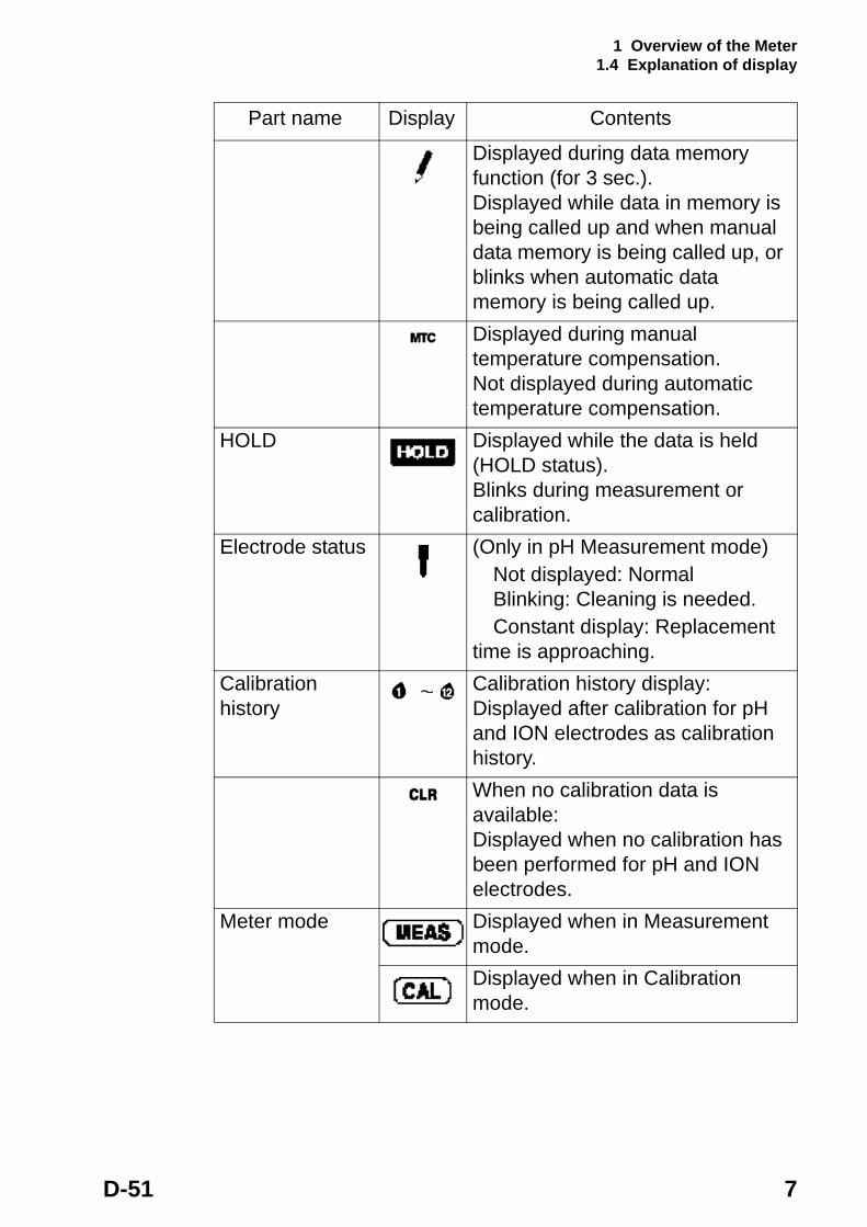
Displayed during data memory function (for 3 sec.).Displayed while data in memory is being called up and when manual data memory is being called up, or blinks when automatic data memory is being called up.Displayed during manual temperature compensation.Not displayed during automatic temperature compensation.
HOLD Displayed while the data is held (HOLD status).Blinks during measurement or calibration.
Electrode status (Only in pH Measurement mode)Not displayed: NormalBlinking: Cleaning is needed.Constant display: Replacement
time is approaching.Calibration history
Calibration history display:Displayed after calibration for pH and ION electrodes as calibration history. When no calibration data is available:Displayed when no calibration has been performed for pH and ION electrodes.
Meter mode Displayed when in Measurement mode.Displayed when in Calibration mode.
Part name Display Contents
1 Overview of the Meter 1.5 Operation keys
8 HORIBA
1.5 Operation keys
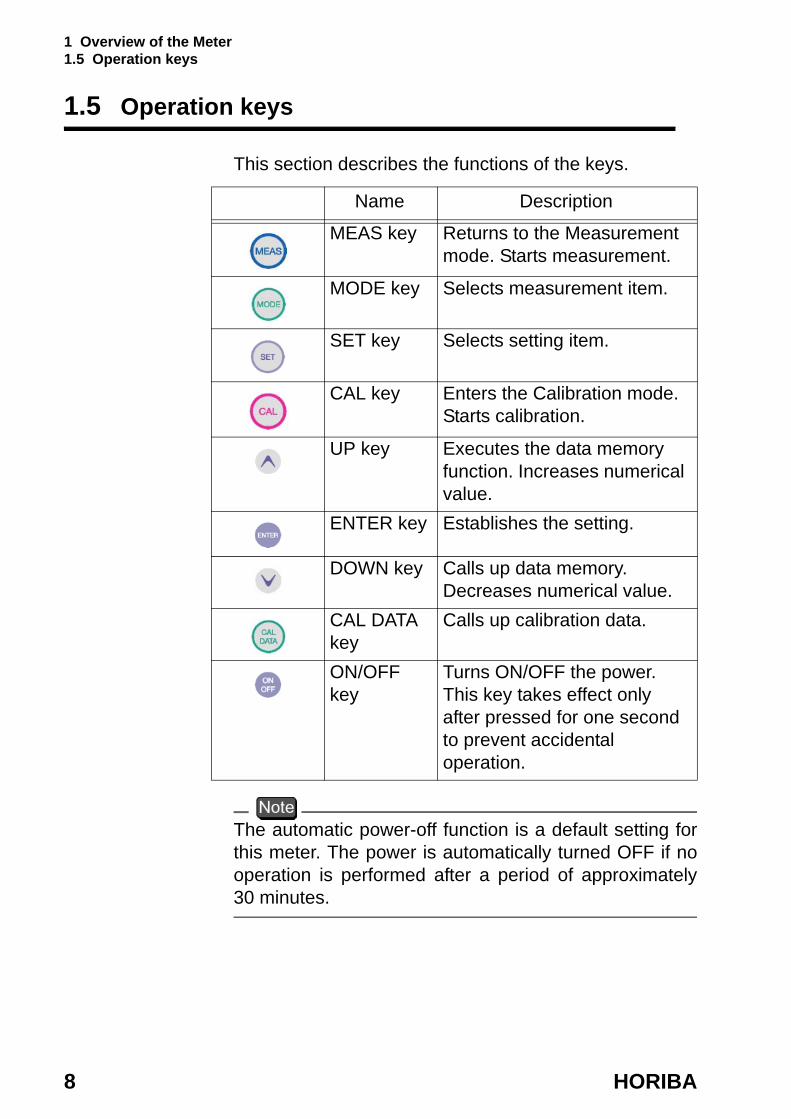
This section describes the functions of the keys.
The automatic power-off function is a default setting for this meter. The power is automatically turned OFF if no operation is performed after a period of approximately 30 minutes.
Name Description
MEAS key Returns to the Measurement mode. Starts measurement.
MODE key Selects measurement item.
SET key Selects setting item.
CAL key Enters the Calibration mode. Starts calibration.
UP key Executes the data memory function. Increases numerical value.
ENTER key Establishes the setting.
DOWN key Calls up data memory. Decreases numerical value.
CAL DATA key
Calls up calibration data.
ON/OFF key
Turns ON/OFF the power. This key takes effect only after pressed for one second to prevent accidental operation.

1 Overview of the Meter 1.6 Connecting the electrodes
D-51 9
1.6 Connecting the electrodes
Connect the electrodes to the meter using the following procedure:
・Do not allow any water to come into contact with the connector.
・Do not touch the connector with uncleaned hands. ・Hold the metal portion when turning the electrode
conenctor.
The following connectors are used depending on electrode type:
Electrode connector (G-R electrode)
1. Insert the electrode connector, making sure to align the connector grooves with the pins in the connector port on the main unit (see photo, ① ). Do not push the electrode with undue force when the pins are not properly aligned.
CH1 Electrode connector:
pH electrode
Temperature connector:
Temperature electrode for CH1
O-ring
pH electrode
CH1

1 Overview of the Meter 1.6 Connecting the electrodes
10 HORIBA
2. Push the electrode connector into the connector port while turning it clockwise, following the grooves (see photo, ① and ② ).
3. Push the connector cover over the connector (see photo, ③ ), being careful to push it straight on without turning it.
The meter will be waterproof only if this cover is placed properly over the connector.
Temperature connector
1. Insert the temperature connector into the jack on the main unit until the O-ring on the electrode cannot be seen at all (see photo, ④ ).
The meter will not be waterproof if the electrode is not inserted properly.
When the temperature electrode is not connected (or is connected improperly), the automatic temperature compensation (ATC) will be 25°C.
1 Overview of the Meter 1.7 Inserting/replacing the dry-cell batteries
D-51 11
1.7 Inserting/replacing the dry-cell batteries
The dry-cell batteries are not placed in the meter before shipping. To insert the batteries, follow the procedure below.Note that if “ERR 2” appears on the display while using the meter, it indicates that the charge of the dry-cell bat- teries is running low. When this occurs, replace the bat- teries promptly.Dry-cell battery type: AA alkaline
・Insert the batteries, paying attention to the orientation of the battery poles (“+” and “-“). ・Removing the batteries will erase the clock data. To save the clock data, remove and replace the batteries while the meter is connected to the AC adapter (sold separately). ・Replace the batteries only after turning the power OFF. Any saved data will not be lost. ・When opening and closing the battery cover, be care-ful that no water gets inside the meter. ・Check that the rubber packing is not twisted and no foreign matter is stuck to it. Otherwise the meter may no longer be waterproof.
The life of the batteries included with the meter may be short because the batteries were used for the operation check before shipping.
To insert/replace the batteries
1. Loosen the screw of the battery cover by using a coin or screwdriver, etc. The cover is constructed so that the stop screw cannot be completely removed and lost.
2. Pull up the screw, and remove the battery cover by sliding it out.
1 Overview of the Meter 1.7 Inserting/replacing the dry-cell batteries
12 HORIBA
3. If there are old batteries inside, remove them.
4. Place the new batteries in the meter, verifying the orientation of the poles (“+” and “-”).
5. Check that the rubber packing is not twisted and no foreign matter is stuck to it.
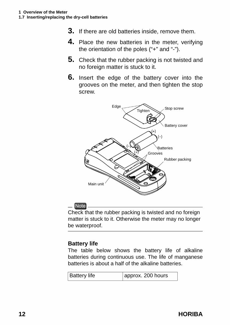
6. Insert the edge of the battery cover into the grooves on the meter, and then tighten the stop screw.
Check that the rubber packing is twisted and no foreign matter is stuck to it. Otherwise the meter may no longer be waterproof.
Battery lifeThe table below shows the battery life of alkaline batteries during continuous use. The life of manganese batteries is about a half of the alkaline batteries.
Battery life approx. 200 hours
Edge
Battery cover
Tighten
BatteriesGrooves
Rubber packing
Main unit
Stop screw

1 Overview of the Meter 1.8 Connecting the AC adapter
D-51 13
1.8 Connecting the AC adapter
When using the meter with an AC power supply, use the designated AC adapter (option).AC adapter specifications
.
When the AC adapter is connected, the meter is no longer waterproof. Be careful not to let water get into the meter.
Supply voltage range 100 - 200 V ACFrequency range 50/60 HzCurrent rating Max 370 mAClass2 Power supplyEquipment pro-tected by double insulationIndoor use onlySupply voltage fluc-tuations allowed up to ± 10%
AC adapter connector
1 Overview of the Meter 1.8 Connecting the AC adapter
14 HORIBA

2 Taking Measurements 2.1 Turning the meter ON/OFF
D-51 15
2 Taking Measurements
This chapter explains how to take basic measurements.
2.1 Turning the meter ON/OFF
Pressing the ON/OFF key turns the power on/off. The ON/OFF key functions when it is pressed continuously for about one second to protect against accidental operation.
2.2 Settings required before measurement
The built-in clock allows you to record the date of calibration and data memory storage. When using the meter for the first time, be sure to set this clock.
“3.3 Displaying and setting the clock” page 34
2 Taking Measurements 2.3 Measurement modes
16 HORIBA
2.3 Measurement modes
The D-51, pH meter has an Instantaneous Value Measurement mode and an Auto Hold Measurement mode for all components of the solution being measured.
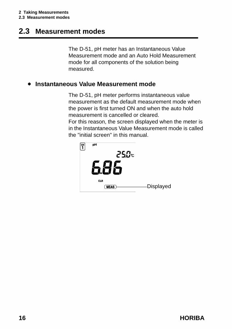
Instantaneous Value Measurement modeThe D-51, pH meter performs instantaneous value measurement as the default measurement mode when the power is first turned ON and when the auto hold measurement is cancelled or cleared.For this reason, the screen displayed when the meter is in the Instantaneous Value Measurement mode is called the "initial screen" in this manual.
Displayed
2 Taking Measurements 2.3 Measurement modes
D-51 17
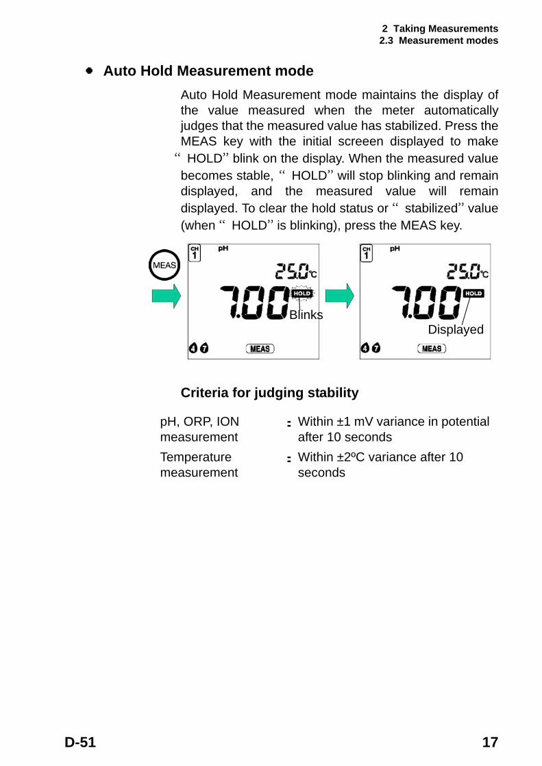
Auto Hold Measurement modeAuto Hold Measurement mode maintains the display of the value measured when the meter automatically judges that the measured value has stabilized. Press the MEAS key with the initial screeen displayed to make
“HOLD” blink on the display. When the measured value becomes stable, “HOLD” will stop blinking and remain displayed, and the measured value will remain displayed. To clear the hold status or “stabilized” value (when “HOLD” is blinking), press the MEAS key.
Criteria for judging stability
BlinksDisplayed
pH, ORP, ION measurement
: Within ±1 mV variance in potential after 10 seconds
Temperature measurement
: Within ±2ºC variance after 10 seconds
2 Taking Measurements 2.4 Selecting the measurement modes
18 HORIBA
2.4 Selecting the measurement modes
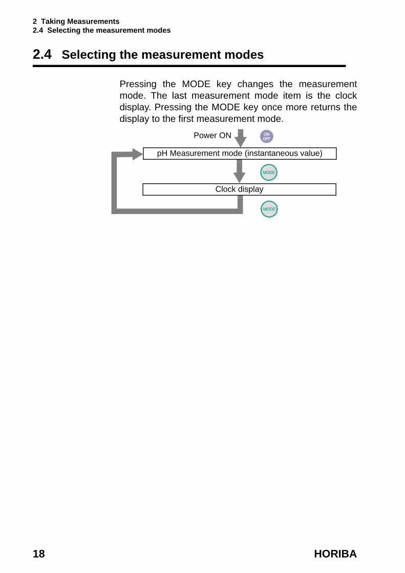
Pressing the MODE key changes the measurement mode. The last measurement mode item is the clock display. Pressing the MODE key once more returns the display to the first measurement mode.
Power ON
Clock display
pH Measurement mode (instantaneous value)

2 Taking Measurements 2.5 Measuring pH
D-51 19
2.5 Measuring pH
The following shows the operational flow for pH measurement.
Measuring pH: basic operational flow
Power ON
1. Electrode preparation
2. pH Measurement mode screen (instantaneous value)“ Setting the clock” page 35
3. Standard solution calibrationPreparation for standard solution“3.4.3 pH standard solution setting” page 37
“3.4.4 Temperature compensation setting” page 41
4. Auto Hold Calibration“ pH repeatability check” page 26 “ pH calibration history” page 32
5. pH Measurement mode screen (instantaneous value)
6. Auto Hold Measurement“3.1 Data memory function” page 29
Clear HOLD

2 Taking Measurements 2.5 Measuring pH
20 HORIBA
Electrode preparationRefer to the electrode instruction manual and make sure you have the necessary electrode(s).Plastic-body pH electrode: 9621-10DGlass-body pH electrode: 9611-10DpH (micro) electrode: 9669-10DpH (sleeve) electrode: 9677-10D
Entering the pH Measurement mode
1. Press the ON/OFF key.The initial screen will appear.
Chemical solution
The liquid inside the electrode is highly concentrated potassium chloride (3.33 mol/L KCl). If the internal solution in the electrode comes in contact with your hands or skin, wash immediately with water. If the internal solution comes in contact with your eyes, flush immediately with large amounts of water and seek treatment by a physician.
Glass fragments
Glass fragments can cause injury.The outer tube of the electrode and the tip of the electrode are made of glass. Use care not to break them.
Caution
Caution

2 Taking Measurements 2.5 Measuring pH
D-51 21
Standard solution calibrationPerform a one-point calibration for making simple pH measurements; for more accurate measurements, perform at least a two-point calibration.
Up to three points can be used for calibration. If you perform calibration for a fourth points, “ERR06 Calibration point error” is displayed.
Standard solutions for calibration are defaulted to pH 2, pH 4, pH 7, pH 9, and pH 12.
“3.4.3 pH standard solution setting” page 37
This section will explain how to conduct a two-point calibration using pH 7 and pH 4 standard solutions.
Calibration procedure
1. Press the CAL key while in the pH Measurement mode.The meter enters the Calibration mode and >CAL< is displayed.
The mode cannot be changed during Auto Hold calibration (while “HOLD” is blinking or continually displayed.
Displayed item differs depending on the standard solution setting.
2 Taking Measurements 2.5 Measuring pH
22 HORIBA
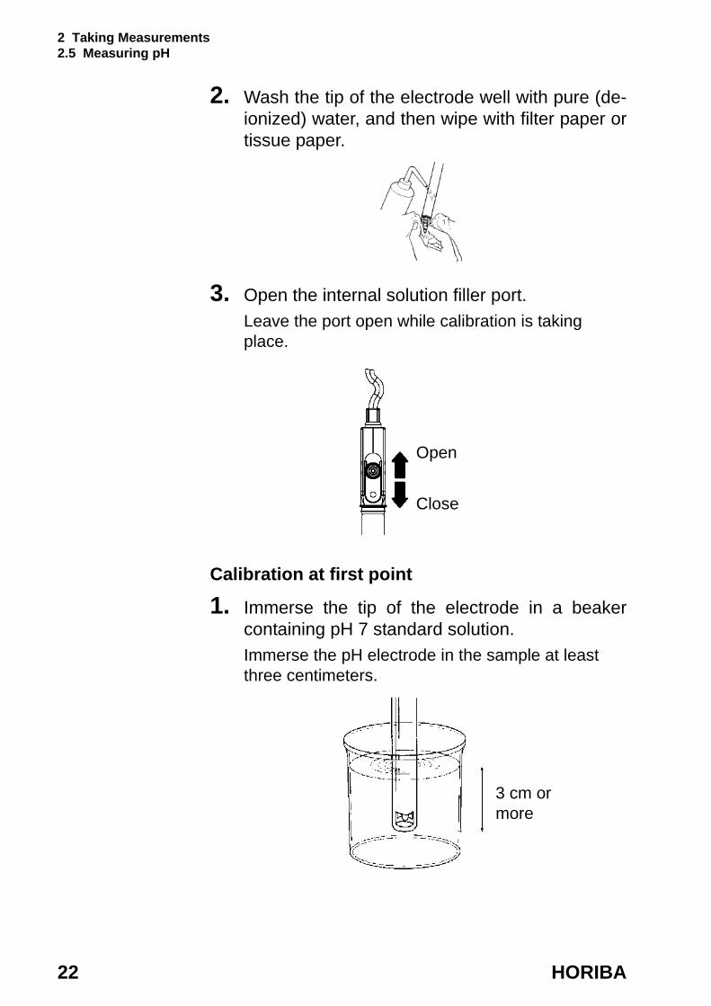
2. Wash the tip of the electrode well with pure (de- ionized) water, and then wipe with filter paper or tissue paper.
3. Open the internal solution filler port.Leave the port open while calibration is taking place.
Calibration at first point
1. Immerse the tip of the electrode in a beaker containing pH 7 standard solution.Immerse the pH electrode in the sample at least three centimeters.
Open
Close
3 cm or more
2 Taking Measurements 2.5 Measuring pH
D-51 23
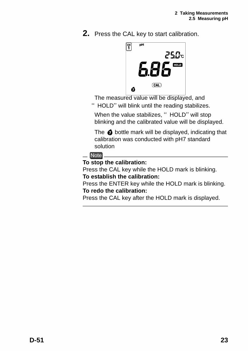
2. Press the CAL key to start calibration.
The measured value will be displayed, and “HOLD” will blink until the reading stabilizes.When the value stabilizes, “HOLD” will stop blinking and the calibrated value will be displayed.
The bottle mark will be displayed, indicating that calibration was conducted with pH7 standard solution
To stop the calibration:Press the CAL key while the HOLD mark is blinking.To establish the calibration:Press the ENTER key while the HOLD mark is blinking.To redo the calibration:Press the CAL key after the HOLD mark is displayed.

2 Taking Measurements 2.5 Measuring pH
24 HORIBA
Calibration at second point
1. Wash the electrode well again with pure (de- ionized) water, and then wipe with filter paper or tissue paper.
2. Immerse the tip of the electrode in a beaker containing pH 4 standard solution.
3. Press the CAL key to start calibration.The measured value will be displayed, and “HOLD” will blink until the reading stabilizes.When the value stabilizes, “HOLD” will stop blinking and the calibrated value will be displayed.
The bottle mark will be displayed, indicating that calibration was conducted with pH 4 standard solution.
4. Press the MEAS key to return to the pH Measurement screen.
While calibrations are being performed in the Calibration mode, redoing a calibration only updates the calibration data for the pertinent standard solution. If a calibration is redone after the meter is returned to the Measurement mode, however, the calibration is conducted on the initial status of the meter; i.e., all the previous calibration data is cleared.
2 Taking Measurements 2.5 Measuring pH
D-51 25
The example of calibration at second point has explained the calibration process using the order from pH 7 to pH 4. However, the calibration order of the standard solutions can be arbitrarily chosen.
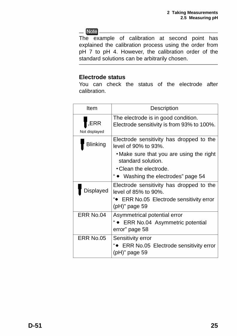
Electrode statusYou can check the status of the electrode after calibration.
Item Description
,ERRNot displayed
The electrode is in good condition. Electrode sensitivity is from 93% to 100%.
BlinkingElectrode sensitivity has dropped to the level of 90% to 93%. ・Make sure that you are using the right
standard solution. ・Clean the electrode.“ Washing the electrodes” page 54
DisplayedElectrode sensitivity has dropped to the level of 85% to 90%.“ ERR No.05 Electrode sensitivity error (pH)” page 59
ERR No.04 Asymmetrical potential error“ ERR No.04 Asymmetric potential error” page 58
ERR No.05 Sensitivity error“ ERR No.05 Electrode sensitivity error (pH)” page 59
2 Taking Measurements 2.5 Measuring pH
26 HORIBA
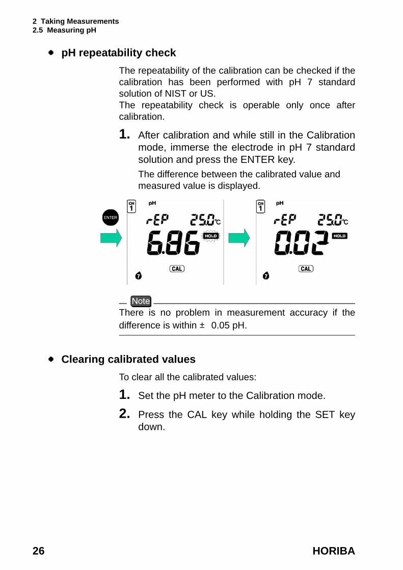
pH repeatability checkThe repeatability of the calibration can be checked if the calibration has been performed with pH 7 standard solution of NIST or US.The repeatability check is operable only once after calibration.
1. After calibration and while still in the Calibration mode, immerse the electrode in pH 7 standard solution and press the ENTER key.The difference between the calibrated value and measured value is displayed.
There is no problem in measurement accuracy if the difference is within ± 0.05 pH.
Clearing calibrated valuesTo clear all the calibrated values:
1. Set the pH meter to the Calibration mode.
2. Press the CAL key while holding the SET key down.
2 Taking Measurements 2.5 Measuring pH
D-51 27
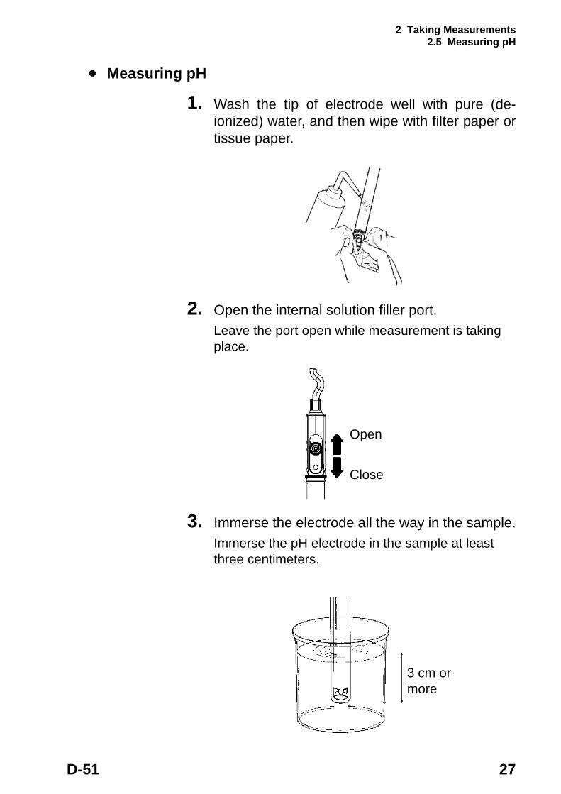
Measuring pH
1. Wash the tip of electrode well with pure (de- ionized) water, and then wipe with filter paper or tissue paper.
2. Open the internal solution filler port.Leave the port open while measurement is taking place.
3. Immerse the electrode all the way in the sample.Immerse the pH electrode in the sample at least three centimeters.
Open
Close
3 cm or more

2 Taking Measurements 2.5 Measuring pH
28 HORIBA
4. Press the MEAS key with the initial screeen displayed.
“HOLD” will blink until the reading stabilizes.When the indicated value stabilizes, “HOLD” will stop blinking and will be displayed. The indicated value will remain displayed continually.
Refer to the “ Criteria for judging stability” page 17 for the criteria for judging the stability of the readout.
When measurement data is held using Instantaneous Value Measurement or Auto Hold Measurement, you can store that data in the memory by pressing the key. See “3.1 Data memory function” page 29.

3 Functions 3.1 Data memory function
D-51 29
3 Functions
This chapter describes the various functions of the pH meter.
3.1 Data memory function
Data memoryIn all measurement modes, you can store data when the instantaneous value is measured or the measured value is held (HOLD status) during the Auto HOLD measurement by pressing the key.The measurement reading is stored along with the temperature, data, HOLD value/instantaneous value, ATC/MTC and calibration point , at the time the mea- surement was taken.After the data number is displayed, the screen returns to the initial screeen. Up to 300 items of data can be stored in the memory. If the number of data items exceeds the maximum limit, ERR 10 is displayed and no more data can be stored.
Data cannot be stored unless the value has stabilized or in the CAL mode.

3 Functions 3.1 Data memory function
30 HORIBA
Calling up memory data
1. Press the key in the Measurement mode to load measurement data.
Select and load the desired memory data item using the and keys. The displayed number returns to 0 after 300, the maximum number.
2. Press the MODE key to display the data and time.
Select the desired data item using the and keys.
3. Press the MODE key to display the ID.
Select the desired data item using the and keys.
Displayed: Manual data memory
Sample temperature
Measurement mode
Data memory No.
Measurement item
Not displayed: Instantaneous value
: Auto HOLD measurement
Calibration point
3 Functions 3.1 Data memory function
D-51 31
If an error occurs while a data number is being displayed, the error number will NOT be displayed. When using a printer (sold separately), press the ENTER key while in the DATA OUT mode to print the data.
3 Functions 3.2 pH calibration history display
32 HORIBA
3.2 pH calibration history display
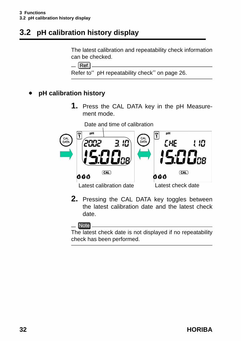
The latest calibration and repeatability check information can be checked.
Refer to“pH repeatability check” on page 26.
pH calibration history
1. Press the CAL DATA key in the pH Measure- ment mode.
2. Pressing the CAL DATA key toggles between the latest calibration date and the latest check date.
The latest check date is not displayed if no repeatability check has been performed.
Latest calibration date Latest check date
Date and time of calibration

3 Functions 3.2 pH calibration history display
D-51 33
Latest calibration data
1. Press the key with latest calibration date displayed.The asymmetrical potential will be displayed.
2. Press the key to show sensitivity display.
Status displayWhen the meter is in a good condition
When the electrode needs washing
When the electrode is old and is going bad
Refer to“Asymmetrical potential display” on page 71.
pH latest check data
1. Press the key with latest check date displayed.The repeatability display will appear.
Asymmetrical potential display Sensitivity display 4-7Example of 3-point calibration
Status
Sensitivity display 7-9
Repeatability display

3 Functions 3.3 Displaying and setting the clock
34 HORIBA
3.3 Displaying and setting the clock
The clock needs to be when the meter is used for the first time or after replacing the batteries.
Displaying the clockPress the MODE key in the Measurement mode to dis- play the clock.
3 Functions 3.3 Displaying and setting the clock
D-51 35
Setting the clock
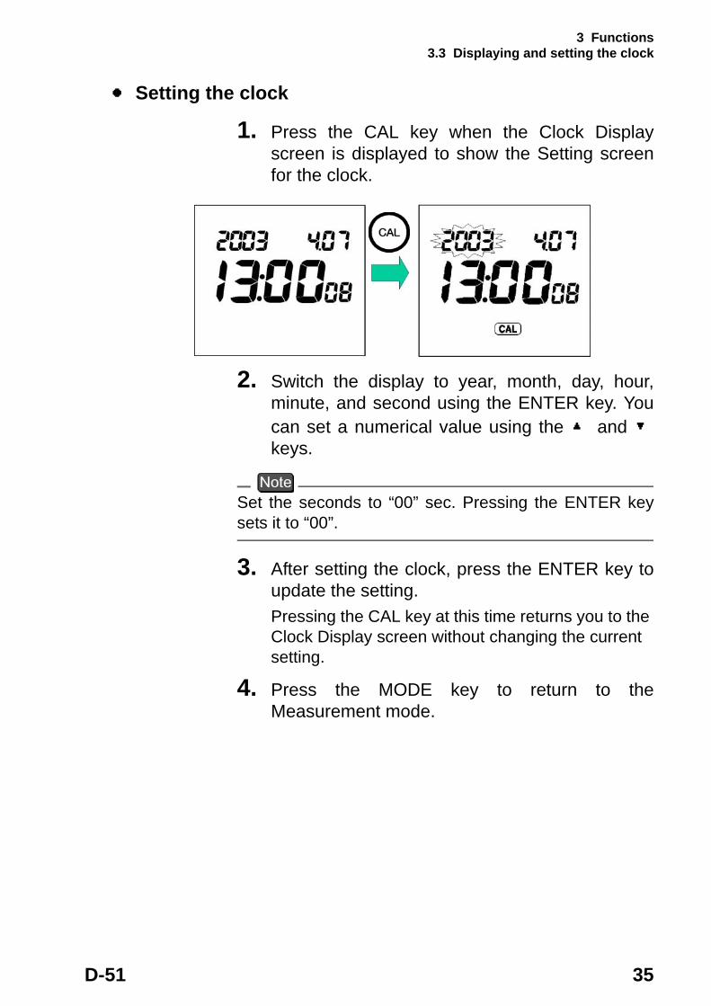
1. Press the CAL key when the Clock Display screen is displayed to show the Setting screen for the clock.
2. Switch the display to year, month, day, hour, minute, and second using the ENTER key. You can set a numerical value using the and keys.
Set the seconds to “00” sec. Pressing the ENTER key sets it to “00”.
3. After setting the clock, press the ENTER key to update the setting.Pressing the CAL key at this time returns you to the Clock Display screen without changing the current setting.
4. Press the MODE key to return to the Measurement mode.

3 Functions 3.4 Setting modes
36 HORIBA
3.4 Setting modes
Selecting the Setting mode expands the uses of the meter.
3.4.1 Entering the Setting mode
1. Press the SET key in the Measurement mode. The Setting Mode Selection cursor appears at the left-bottom of the screen to indicate that the Setting mode is active.
2. Pressing the SET key moves the Setting Mode Selection cursor one by one to allow you to select the Setting mode of your choice.
3. Press the MEAS key to return to the Measurement mode from the Setting mode.
Display
Setting Mode Selection cursor
Setting mode items
Setting Mode Selection cursor
3 Functions 3.4 Setting modes
D-51 37
3.4.2 Display and description
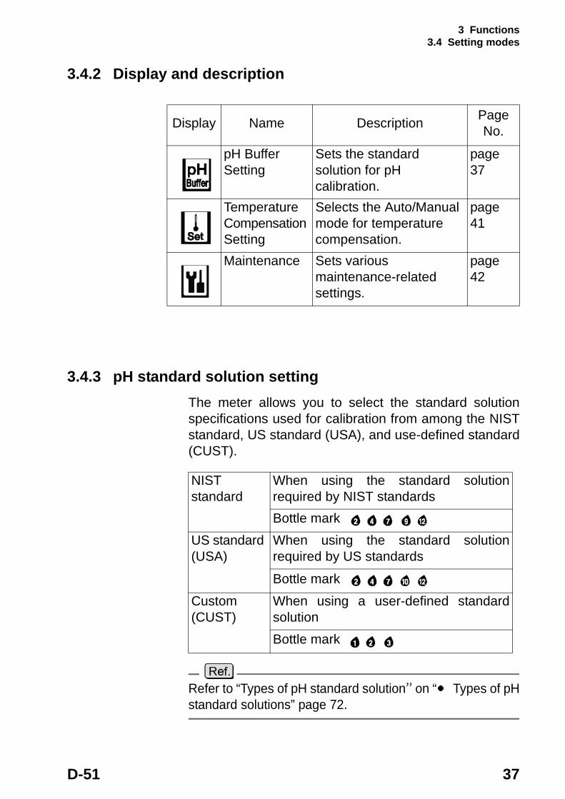
3.4.3 pH standard solution settingThe meter allows you to select the standard solution specifications used for calibration from among the NIST standard, US standard (USA), and use-defined standard (CUST).
Refer to “Types of pH standard solution” on “ Types of pH standard solutions” page 72.
Display Name Description Page No.
pH Buffer Setting
Sets the standard solution for pH calibration.
page 37
Temperature Compensation Setting
Selects the Auto/Manual mode for temperature compensation.
page 41
Maintenance Sets various maintenance-related settings.
page 42
NIST standard
When using the standard solution required by NIST standardsBottle mark
US standard (USA)
When using the standard solution required by US standardsBottle mark
Custom (CUST)
When using a user-defined standard solutionBottle mark

3 Functions 3.4 Setting modes
38 HORIBA
The calibrated value for pH 7 standard solution is different between the NIST standards and US standards.
NIST standard: pH 6.86 (at 25°C) US standard: pH 7.00 (at 25°C)

3 Functions 3.4 Setting modes
D-51 39
Changing the standard solution setting
1. Press the SET key in the Measurement mode and select the pH Buffer Setting mode.
2. Press the ENTER key to toggle between NIST standard, US standard (USA) and a user- defined standard (CUST).
3. Press the MEAS key to return to the Measurement mode.
3 Functions 3.4 Setting modes
40 HORIBA
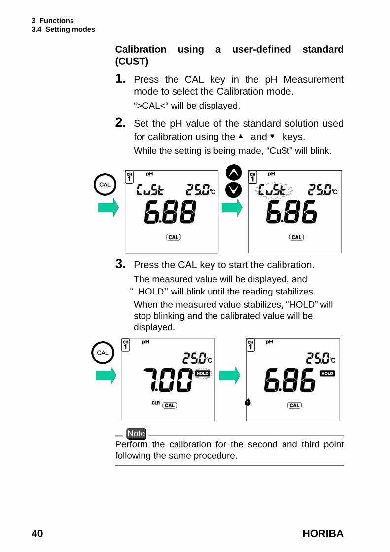
Calibration using a user-defined standard (CUST)
1. Press the CAL key in the pH Measurement mode to select the Calibration mode.“>CAL<“ will be displayed.
2. Set the pH value of the standard solution used for calibration using the and keys. While the setting is being made, “CuSt” will blink.
3. Press the CAL key to start the calibration.The measured value will be displayed, and “HOLD” will blink until the reading stabilizes.When the measured value stabilizes, “HOLD” will stop blinking and the calibrated value will be displayed.
Perform the calibration for the second and third point following the same procedure.

3 Functions 3.4 Setting modes
D-51 41
3.4.4 Temperature compensation setting
1. Press the SET key in the Measurement mode to enter the Temperature Compensation Setting mode.
2. Pressing the ENTER key toggles between MTC and ATC settings.
ATCAutomatic temperature compensation (when using a temperature sensor of the electrode)ATC is displayed.When a temperature sensor is connected, the current temperature is automatically displayed.(When no temperature sensor is connected, the display shows 25°C.)
MTCManual temperature compensation (when an electrode temperature sensor is not being used and the temperature of the solution is known before hand)MTC is displayed.Set the temperature using the and keys.Setting range: 0.0 to 100.0°C
ATC MTC
3 Functions 3.4 Setting modes
42 HORIBA
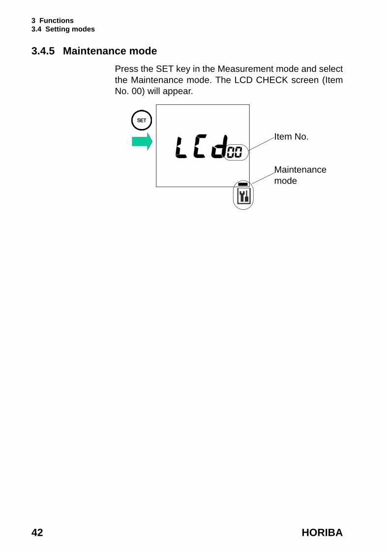
3.4.5 Maintenance modePress the SET key in the Measurement mode and select the Maintenance mode. The LCD CHECK screen (Item No. 00) will appear.
Item No.
Maintenance mode

3 Functions 3.4 Setting modes
D-51 43
Maintenance setting itemsUse the MODE key to toggle between Maintenance mode items.
Item No. Item Description Page
No.
00 LCD check Enables check to see if all LCD segments are displayed.
page 44
01 Battery voltage check
Enables simple battery voltage check.
page 45
02 Temperature zero adjustment
Carries out temperature calibration when the temperature sensor is immersed in a liquid of known temperature.
page 46
03 Automatic power-off setting
Turns Automatic Power-off function ON/OFF and sets time period after which the power will be turned off when no keys are touched.
page 47
05 Remaining data memoriy
Displays number of data items that can still be stored.
page 48
06 Data memory clear
Clears all data in the data memory.
page 48
07 Initialization of setting
Initializes all settings to default values.
page 49
3 Functions 3.4 Setting modes
44 HORIBA
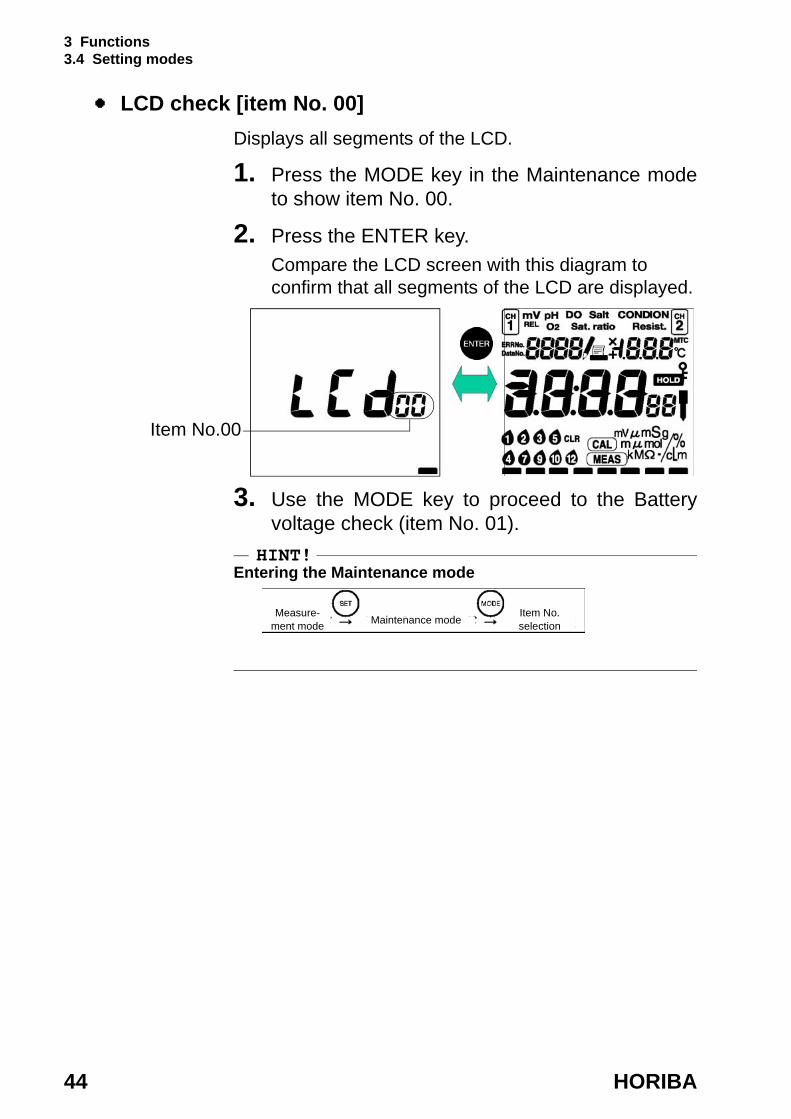
LCD check [item No. 00]Displays all segments of the LCD.
1. Press the MODE key in the Maintenance mode to show item No. 00.
2. Press the ENTER key.Compare the LCD screen with this diagram to confirm that all segments of the LCD are displayed.
3. Use the MODE key to proceed to the Battery voltage check (item No. 01).
HINT!Entering the Maintenance mode
Item No.00
Item No. selectionMaintenance modeMeasure-
ment mode
3 Functions 3.4 Setting modes
D-51 45
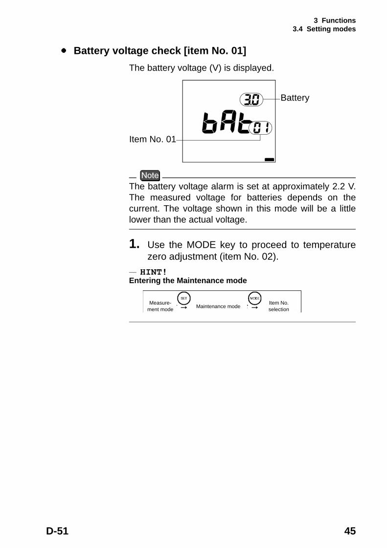
Battery voltage check [item No. 01]The battery voltage (V) is displayed.
The battery voltage alarm is set at approximately 2.2 V. The measured voltage for batteries depends on the current. The voltage shown in this mode will be a little lower than the actual voltage.
1. Use the MODE key to proceed to temperature zero adjustment (item No. 02).
HINT!Entering the Maintenance mode
Item No. 01
Battery
Item No. selectionMaintenance modeMeasure-
ment mode
3 Functions 3.4 Setting modes
46 HORIBA
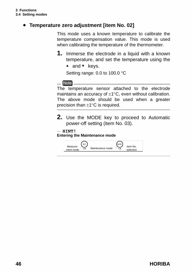
Temperature zero adjustment [item No. 02]This mode uses a known temperature to calibrate the temperature compensation value. This mode is used when calibrating the temperature of the thermometer.
1. Immerse the electrode in a liquid with a known temperature, and set the temperature using the and keys. Setting range: 0.0 to 100.0 °C
The temperature sensor attached to the electrode maintains an accuracy of ±1°C, even without calibration. The above mode should be used when a greater precision than ±1°C is required.
2. Use the MODE key to proceed to Automatic power-off setting (item No. 03).
HINT!Entering the Maintenance mode
Item No. selectionMaintenance modeMeasure-
ment mode
3 Functions 3.4 Setting modes
D-51 47
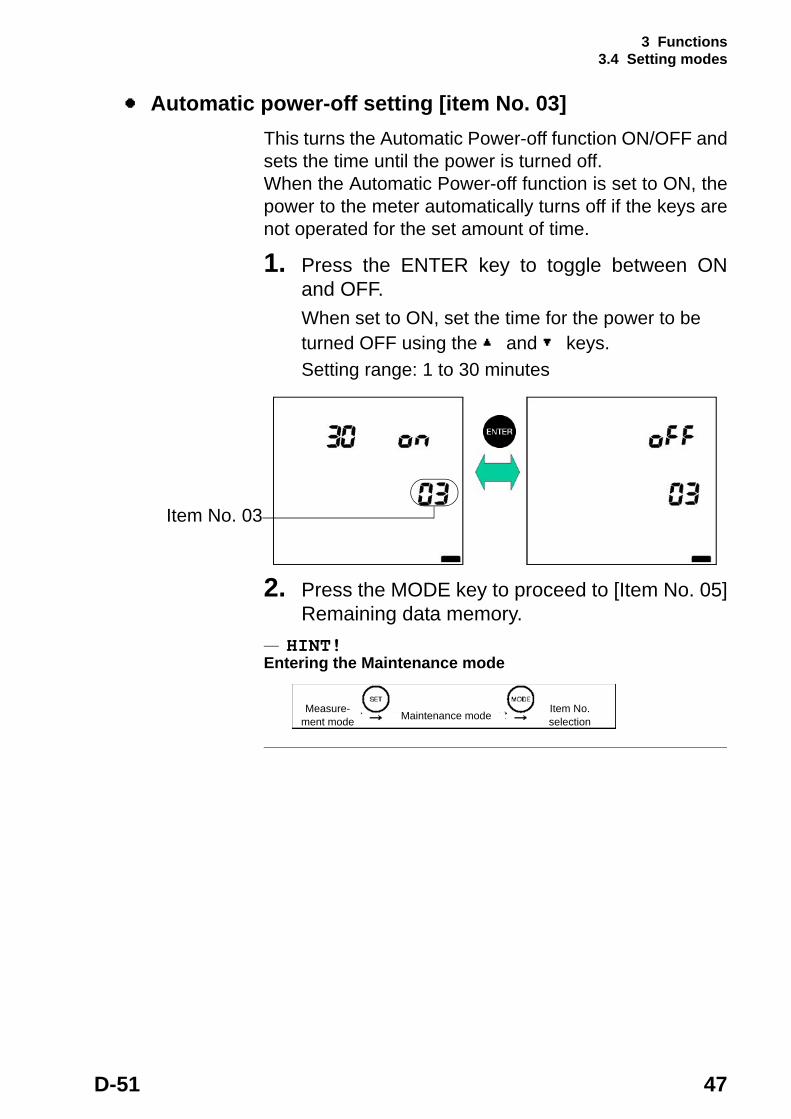
Automatic power-off setting [item No. 03]This turns the Automatic Power-off function ON/OFF and sets the time until the power is turned off.When the Automatic Power-off function is set to ON, the power to the meter automatically turns off if the keys are not operated for the set amount of time.
1. Press the ENTER key to toggle between ON and OFF.When set to ON, set the time for the power to be turned OFF using the and keys.Setting range: 1 to 30 minutes
2. Press the MODE key to proceed to [Item No. 05] Remaining data memory.
HINT!Entering the Maintenance mode
Item No. 03
Item No. selectionMaintenance modeMeasure-
ment mode
3 Functions 3.4 Setting modes
48 HORIBA
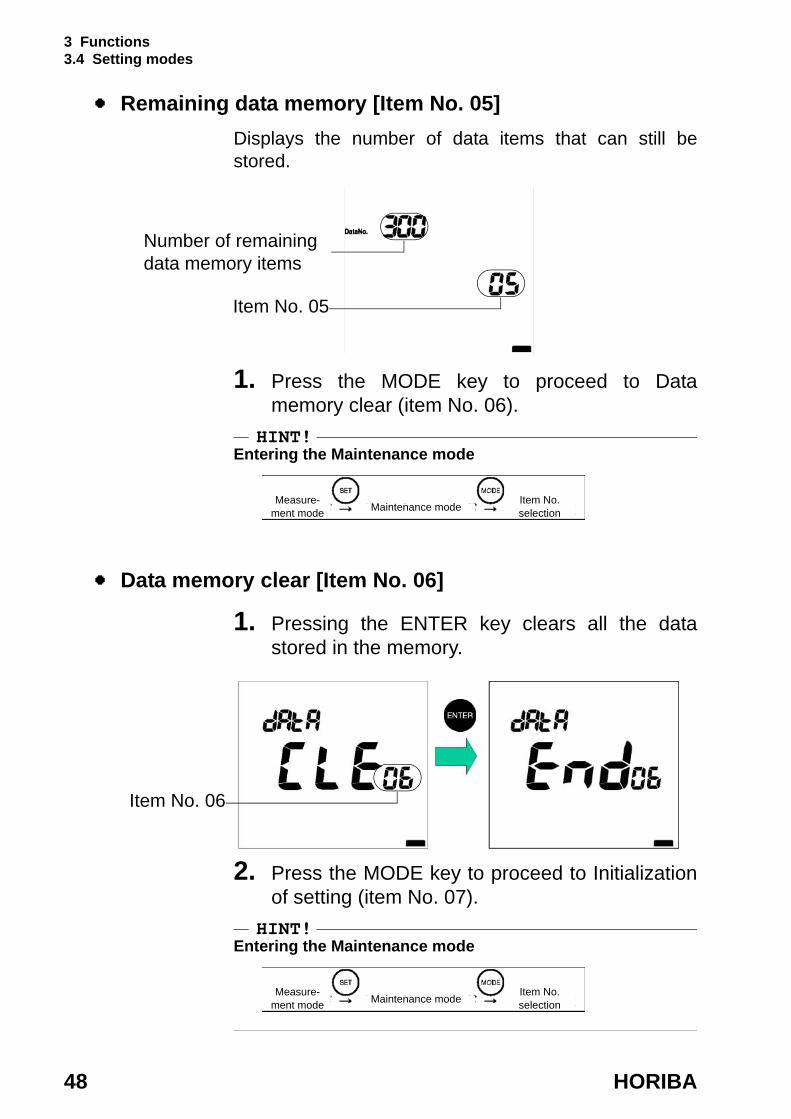
Remaining data memory [Item No. 05]Displays the number of data items that can still be stored.
1. Press the MODE key to proceed to Data memory clear (item No. 06).
HINT!Entering the Maintenance mode
Data memory clear [Item No. 06]
1. Pressing the ENTER key clears all the data stored in the memory.
2. Press the MODE key to proceed to Initialization of setting (item No. 07).
HINT!Entering the Maintenance mode
Item No. 05
Number of remaining data memory items
Item No. selectionMaintenance modeMeasure-
ment mode
Item No. 06
Item No. selectionMaintenance modeMeasure-
ment mode

3 Functions 3.4 Setting modes
D-51 49
Initialization of setting [item No. 07]This mode returns all settings to the default settings. Use this mode to return the pH meter to the original set- tings when the meter was purchased.
1. Press the ENTER key to initialized the settings.
The setting values to be initialized are shown on page 77.
HINT!Entering the Maintenance mode
2. Press the MODE key to return to the first item in the maintenance modes, LCD check.
Test print format
HINT!Entering the Maintenance mode
Item No. 07
Item No. selectionMaintenance modeMeasure-
ment mode
Item No. selectionMaintenance modeMeasure-
ment mode

3 Functions 3.4 Setting modes
50 HORIBA

4 Maintenance and Troubleshooting 4.1 pH electrode maintenance
D-51 51
4 Maintenance and Troubleshooting
This chapter explains how to perform daily meter maintenance and how to deal with error messages.Daily maintenance is vital in assuring accurate measurement and preventing breakdowns before they occur. Maintenance of the electrodes is especially important; if ignored, various problems and erroneous measurements may result. This meter is equipped with a convenient error message function. If an error message is displayed, be sure to take appropriate action.
4.1 pH electrode maintenance
Maintain your electrodes by referring to the following information or to the operation manuals for the electrodes.
Maintenance after daily useAfter taking measurements, wash the electrode using pure water (de-ionized water), wipe off the water from the electrode with filter paper or tissue paper, and store it with its cap on.
Injury warning
Glass fragments can cause injury.The outer tube of the electrode and the tip of the electrode are made of glass. Use care not to break them.
Caution
4 Maintenance and Troubleshooting 4.1 pH electrode maintenance
52 HORIBA
The liquid junction may become clogged if the electrode is left in distilled water.
Extended storageWhen an electrode is not to be used for a long period of time, store the electrode after performing the following steps. Also, replace the reference solution every three to six months, using the method explained below.
1. Remove the electrode from the pH meter.
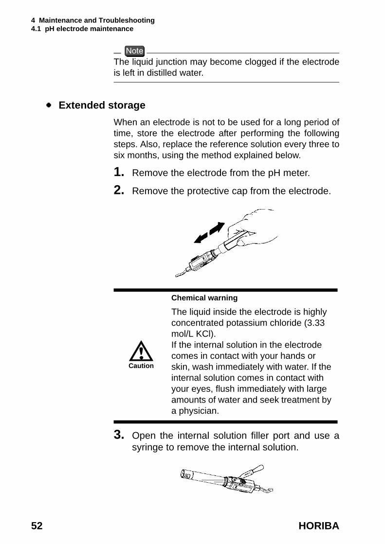
2. Remove the protective cap from the electrode.
3. Open the internal solution filler port and use a syringe to remove the internal solution.
Chemical warning
The liquid inside the electrode is highly concentrated potassium chloride (3.33 mol/L KCl).If the internal solution in the electrode comes in contact with your hands or skin, wash immediately with water. If the internal solution comes in contact with your eyes, flush immediately with large amounts of water and seek treatment by a physician.
Caution
4 Maintenance and Troubleshooting 4.1 pH electrode maintenance
D-51 53
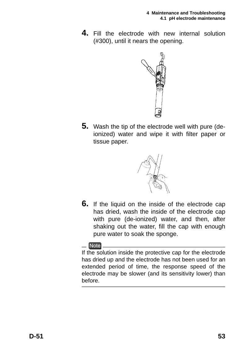
4. Fill the electrode with new internal solution (#300), until it nears the opening.
5. Wash the tip of the electrode well with pure (de- ionized) water and wipe it with filter paper or tissue paper.
6. If the liquid on the inside of the electrode cap has dried, wash the inside of the electrode cap with pure (de-ionized) water, and then, after shaking out the water, fill the cap with enough pure water to soak the sponge.
If the solution inside the protective cap for the electrode has dried up and the electrode has not been used for an extended period of time, the response speed of the electrode may be slower (and its sensitivity lower) than before.

4 Maintenance and Troubleshooting 4.1 pH electrode maintenance
54 HORIBA
Washing the electrodesIf the tip of the pH electrode is extremely dirty, the speed of its response may slow and it may cause errors in measurement. If the electrode is so dirty that it cannot be cleaned by rinsing with pure (de-ionized) water, wash the electrode using the most appropriate method below.
General dirt & oily grimeWipe the dirt/grime off using cotton gauze that contains a neutral detergent.
Inorganic grimeRinse using a hydrochloric acid solution or cleaning liq- uid (#220) of approximately 1 mol/L. Be sure not to soak the electrode in strong acid for a long period of time.
4 Maintenance and Troubleshooting 4.2 Troubleshooting
D-51 55
4.2 Troubleshooting
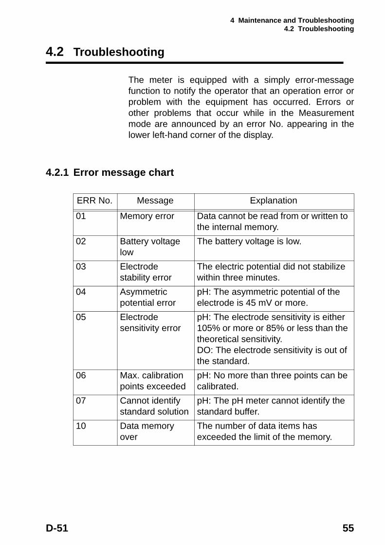
The meter is equipped with a simply error-message function to notify the operator that an operation error or problem with the equipment has occurred. Errors or other problems that occur while in the Measurement mode are announced by an error No. appearing in the lower left-hand corner of the display.
4.2.1 Error message chart
ERR No. Message Explanation
01 Memory error Data cannot be read from or written to the internal memory.
02 Battery voltage low
The battery voltage is low.
03 Electrode stability error
The electric potential did not stabilize within three minutes.
04 Asymmetric potential error
pH: The asymmetric potential of the electrode is 45 mV or more.
05 Electrode sensitivity error
pH: The electrode sensitivity is either 105% or more or 85% or less than the theoretical sensitivity.DO: The electrode sensitivity is out of the standard.
06 Max. calibration points exceeded
pH: No more than three points can be calibrated.
07 Cannot identify standard solution
pH: The pH meter cannot identify the standard buffer.
10 Data memory over
The number of data items has exceeded the limit of the memory.

4 Maintenance and Troubleshooting 4.2 Troubleshooting
56 HORIBA
ERR No. 01 Memory error
ExplanationData cannot be read from or written to the internal memory.
ERR No. 02 Battery voltage low
ExplanationThe battery has insufficient voltage.
The measured value cannot be guaranteed when ERR No. 02 is displayed.
Cause How to solve problem
The pH meter does not start operating cor-rectly even after the power is turned ON.
Take the battery from the pH meter, and disconnect the AC adapter. Then press the ON/OFF key for about 10 seconds.
The internal IC is defective.
Seek repairs at your nearest retail outlet or HORIBA service station.
Cause How to solve problem
The battery voltage is low.(Battery voltage: 2.2V or less)
Replace the dry-cell battery.

4 Maintenance and Troubleshooting 4.2 Troubleshooting
D-51 57
ERR No.03 Electrode stability error
ExplanationThe electric potential did not stabilize within three minutes.
Cause How to solve problem
This is caused by the sample solution (when the sample solution is pure water or another solution with low conductivity or the pH concentration or temperature change).
Press the MEAS key again while “HOLD” is either brinking or steadily lit in the display, to measure the sample using instantaneous value measurement.
The electrode is dirty.
Wash the electrode.
The electrode is cracked.
Replace the electrode.
The responsive glass membrane of the electrode has been dry for a long time.
Soak the membrane (on the electrode) in pure (de-ionized) water for 24 hours.
The temperature of the sample solution is fluctuating.
Measure after the sample solution temperature stabilizes.
4 Maintenance and Troubleshooting 4.2 Troubleshooting
58 HORIBA
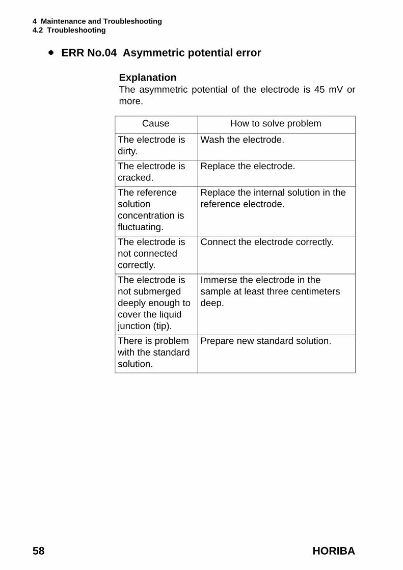
ERR No.04 Asymmetric potential error
ExplanationThe asymmetric potential of the electrode is 45 mV or more.
Cause How to solve problem
The electrode is dirty.
Wash the electrode.
The electrode is cracked.
Replace the electrode.
The reference solution concentration is fluctuating.
Replace the internal solution in the reference electrode.
The electrode is not connected correctly.
Connect the electrode correctly.
The electrode is not submerged deeply enough to cover the liquid junction (tip).
Immerse the electrode in the sample at least three centimeters deep.
There is problem with the standard solution.
Prepare new standard solution.
4 Maintenance and Troubleshooting 4.2 Troubleshooting
D-51 59
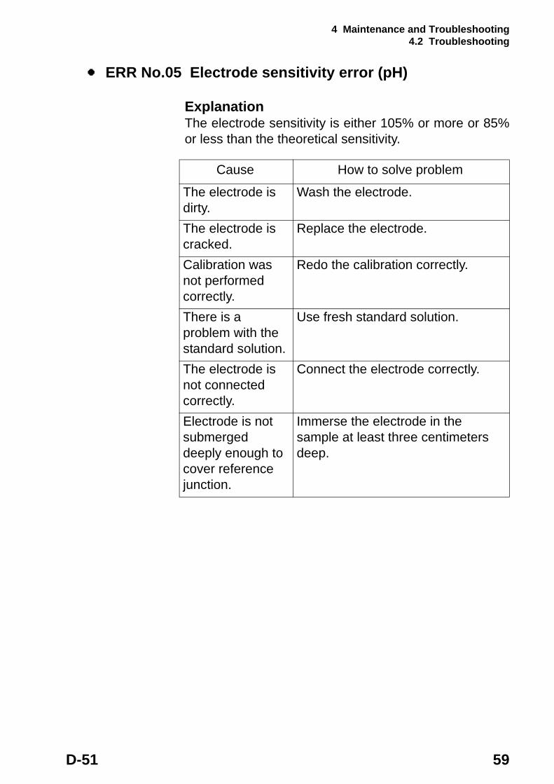
ERR No.05 Electrode sensitivity error (pH)
ExplanationThe electrode sensitivity is either 105% or more or 85% or less than the theoretical sensitivity.
Cause How to solve problem
The electrode is dirty.
Wash the electrode.
The electrode is cracked.
Replace the electrode.
Calibration was not performed correctly.
Redo the calibration correctly.
There is a problem with the standard solution.
Use fresh standard solution.
The electrode is not connected correctly.
Connect the electrode correctly.
Electrode is not submerged deeply enough to cover reference junction.
Immerse the electrode in the sample at least three centimeters deep.
4 Maintenance and Troubleshooting 4.2 Troubleshooting
60 HORIBA
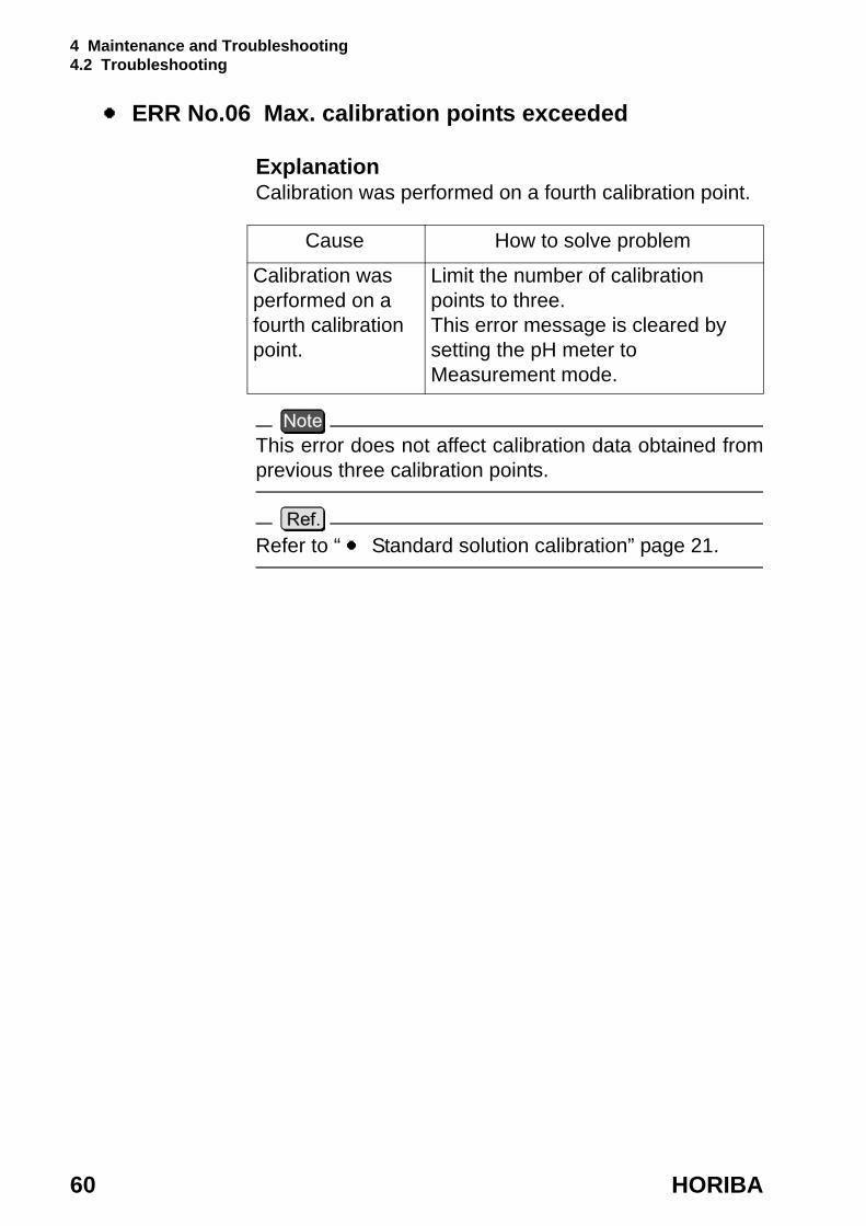
ERR No.06 Max. calibration points exceeded
ExplanationCalibration was performed on a fourth calibration point.
This error does not affect calibration data obtained from previous three calibration points.
Refer to “ Standard solution calibration” page 21.
Cause How to solve problem
Calibration was performed on a fourth calibration point.
Limit the number of calibration points to three. This error message is cleared by setting the pH meter to Measurement mode.

4 Maintenance and Troubleshooting 4.2 Troubleshooting
D-51 61
ERR No.07 Cannot identify standard solution
ExplanationIf the automatic standard-solution identification function of the meter does not work, recalibrate the meter after performing the appropriate measures below.
ERR No.10 Data memory over
ExplanationThe number of data items has exceeded the limit of the memory.
Cause How to solve problem
There is a problem with the standard solution.
Prepare new standard solution.
There is a problem with the standard solution setting.
Check the NIST or US standards settings and the kind of standard solution used for calibration, and make sure they match.
The responsive membrane is dry or dirty.
Measure after washing the responsive membrane and soaking it in pure (de-ionized) water for 24 hours.
The reference solution is contaminated.
Replace the reference solution with new solution.
The responsive membrane is damaged or worn out.
Replace the electrode.
Cause How to solve problem
Memory over Delete data stored in the memory after confirming their contents.

4 Maintenance and Troubleshooting 4.2 Troubleshooting
62 HORIBA
4.2.2 More troubleshootingThis section explains how to respond to various symptoms of trouble that are not indicated by an error number.
Nothing shows up on the display when the power is turned ON
Cause How to solve problem
No batteries Place batteries in the meter.The batteries are loaded with the poles reversed.
Re-insert the batteries with the poles correctly oriented.
The battery voltage is low.
Remove the old batteries and correctly insert new dry-cell batteries.Or connect the unit to the optional AC adapter.

4 Maintenance and Troubleshooting 4.2 Troubleshooting
D-51 63
The indicated value fluctuates
When there is a problem with the electrode...
When there is a problem with the main unit of the pH meter...
Cause How to solve problem
The responsive membrane is dry or dirty.
Wash the responsive membrane.
The responsive membrane is damaged or worn out.
Replace the electrode.
There are air bubbles on the electrode.
Shake the electrode to remove the air bubbles.
There is no reference solution remaining.
Fill the electrode with new reference solution, as noted in the electrode operation manual.
The wrong reference solution is being used.
Use the correct reference solution.
Cause How to solve problem
There is a motor or other device causing electrical interference.
Move the meter to a place where it is not subject to dielectric effects. Be sure to ground devices that are using commercial electricity.
The electrode is not connected correctly.
Connect the electrode correctly.
4 Maintenance and Troubleshooting 4.2 Troubleshooting
64 HORIBA
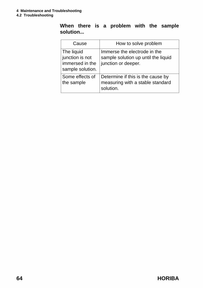
When there is a problem with the sample solution...
Cause How to solve problem
The liquid junction is not immersed in the sample solution.
Immerse the electrode in the sample solution up until the liquid junction or deeper.
Some effects of the sample
Determine if this is the cause by measuring with a stable standard solution.
4 Maintenance and Troubleshooting 4.2 Troubleshooting
D-51 65
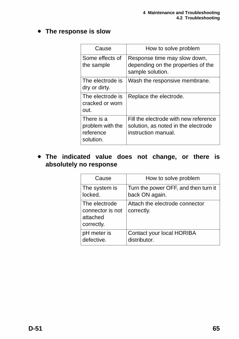
The response is slow
The indicated value does not change, or there is absolutely no response
Cause How to solve problem
Some effects of the sample
Response time may slow down, depending on the properties of the sample solution.
The electrode is dry or dirty.
Wash the responsive membrane.
The electrode is cracked or worn out.
Replace the electrode.
There is a problem with the reference solution.
Fill the electrode with new reference solution, as noted in the electrode instruction manual.
Cause How to solve problem
The system is locked.
Turn the power OFF, and then turn it back ON again.
The electrode connector is not attached correctly.
Attach the electrode connector correctly.
pH meter is defective.
Contact your local HORIBA distributor.

4 Maintenance and Troubleshooting 4.2 Troubleshooting
66 HORIBA
The measured value is blinkingThe pH value exceeds the measurement range (when pH value is displayed).
Measurement range: pH 0.00 – pH 14.00
Check this pointAs shown in the diagram, use a jumper wire or bent paper clip to short the meter by touching both the center pin and some metal part in the electrode connector.If the flaching measured value disappears when this done, the meter is nomal.
Cause How to solve problem
The sample solution is inappropriate.
Change to a sample solution with properties within the measurement range.
The liquid junction is not immersed in the sample solution.
Immerse the electrode in the sample solution all the way until the liquid junction or deeper.
The electrode cable has been severed.
Replace the electrode.
The main body of the pH meter is defective.
Check the point described below.
The meter has not been calibrated or it has been calibrated incorrectly.
Calibrate the meter correctly.
4 Maintenance and Troubleshooting 4.2 Troubleshooting
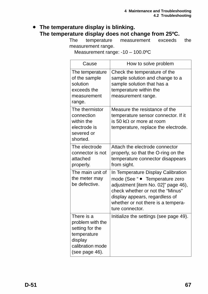
D-51 67
The temperature display is blinking. The temperature display does not change from 25ºC.
The temperature measurement exceeds the measurement range.
Measurement range: -10 – 100.0ºC
Cause How to solve problem
The temperature of the sample solution exceeds the measurement range.
Check the temperature of the sample solution and change to a sample solution that has a temperature within the measurement range.
The thermistor connection within the electrode is severed or shorted.
Measure the resistance of the temperature sensor connector. If it is 50 kΩ or more at room temperature, replace the electrode.
The electrode connector is not attached properly.
Attach the electrode connector properly, so that the O-ring on the temperature connector disappears from sight.
The main unit of the meter may be defective.
In Temperature Display Calibration mode (See “ Temperature zero adjustment [item No. 02]” page 46), check whether or not the “Minus” display appears, regardless of whether or not there is a tempera-ture connector.
There is a problem with the setting for the temperature display calibration mode (see page 46).
Initialize the settings (see page 49).

4 Maintenance and Troubleshooting 4.2 Troubleshooting
68 HORIBA
Measurements are not repeatable
Cause How to solve problem
Some effects of the sample solution
The pH or other properties of the sample solution may have changed over time, making repeatability poor.
The responsive membrane is dry or dirty.
Wash the responsive membrane.
There is not enough reference solution or it is dirty.
Replace the reference solution with new solution.
The responsive membrane is cracked or worn out.
Replace the electrode.
5 Reference
D-51 69
5 Reference
This chapter provides a simple compilation of information for those who would like to know about the functions of the main unit of the meter and other measurement principles in greater detail.It also serves as a reference for spare and optional parts.
5 Reference 5.1 pH measurement
70 HORIBA
5.1 pH measurement
pH measurement and temperatureThe temperature of the solution being inspected is an important parameter in the accurate measurement of pH. There are many possible sources of errors during measurement, such as the state of the solution junction potential, asymmetric potential, and reference solution pH concentration, but all of these items contain factors that change with temperature. The best way to minimize these potential causes of errors is to keep the temperature of the pH standard solution uniform at the time of calibration.
Liquid junction potential“Liquid junction potential” is the electric potential that occurs to a greater or lesser degree at the liquid junction. The size of the electric potential differs depending on the type of solution, the temperature of the solution, and the structure of the liquid junction.When solutions of different compositions come in contact, ION diffusion occurs on the contact surface between the two solutions. The ions are of various sizes, so a difference occurs in the diffusion transfer speed.As diffusion proceeds, a difference in charges occurs on the contact surface of the two solutions, giving rise to a difference in potential. This potential works to reduce the transfer speed of fast ions and increase the speed of slow ions, ultimately achieving a state of equilibrium when the transfer speed of the positive and negative ions on the contact surface of the two solutions is equal. In this state of equilibrium, the potential at the contact surface between the two solutions is called the “liquid junction potential.” A large liquid junction potential means measurements will be very inaccurate.
5 Reference 5.1 pH measurement
D-51 71
Asymmetric potentialThe glass electrode is immersed in a pH 7 reference solution. When the electrode is immersed in the pH 7 solution, both the internal and external sides of the electrode membrane are supposed to take on a pH of 7, making the potential 0. In actuality, however, a potential does occur. This potential is called “asymmetric potential.” The size of the asymmetric potential differs depending on any stress that may have occurred during the processing of the glass and the shape and compositions of the glass. Asymmetric potential also changes depending on the degree of contamination of the reference solution and the state of the glass membrane. Also, if the electrode membrane dries out, a large asymmetric potential will occur, giving rise to measurement errors.

5 Reference 5.1 pH measurement
72 HORIBA
Temperature compensationThe electromotive force generated by the glass electrode changes depending on the temperature of the solution. “Temperature compensation” is used to compensate for the change in electromotive forces caused by temperature. There is absolutely no relation between the change in pH caused by the temperature of the solution and temperature compensation. This is often misunderstood. When pH is to be measured, the temperature of the solution when the pH is measured must be recorded along with that pH value, even if a meter that has automatic temperature compensation is used. If the solution temperature is not recorded, the results of the pH measurement are relatively meaningless.
Types of pH standard solutionsWhen measuring pH, the pH meter must be calibrated using a standard solution. There are several kinds of standard solutions. For normal measurement, three standard solutions—with a pH of 4, 7, and 9—are sufficient to accurately calibrate the meter. ・pH 1.68 standard solution: Oxalate
0.05 mol/L tetra-potassium oxalate aqueous solution ・pH 4.00 standard solution: Phthalate
0.05 mol/L potassium hydrogen phthalate aqueous solution
・pH 6.86 standard solution: Neutral phosphate 0.025 mol/L potassium dihydrogen phosphate, 0.025 mol/L sodium dihydrogenphosphate aqueous solution
・pH 9.18 standard solution: Borate 0.01 mol/L tetra-sodium boric acid (boric sand) aqueous solution
・pH 12.45 standard solution: Saturated calcium hydroxide solution
5 Reference 5.1 pH measurement
D-51 73
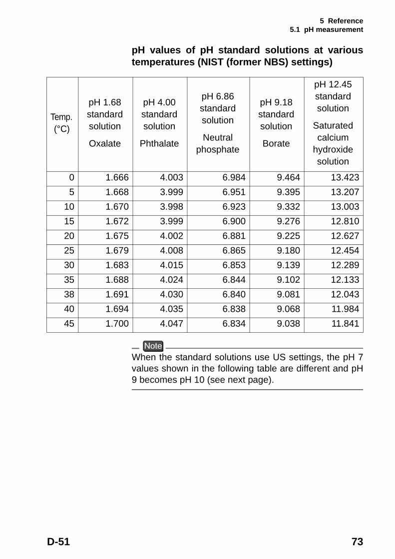
pH values of pH standard solutions at various temperatures (NIST (former NBS) settings)
When the standard solutions use US settings, the pH 7 values shown in the following table are different and pH 9 becomes pH 10 (see next page).
Temp. (°C)
pH 1.68 standard solution
Oxalate
pH 4.00 standard solution
Phthalate
pH 6.86 standard solution
Neutral phosphate
pH 9.18 standard solution
Borate
pH 12.45 standard solution
Saturated calcium
hydroxide solution
0 1.666 4.003 6.984 9.464 13.4235 1.668 3.999 6.951 9.395 13.207
10 1.670 3.998 6.923 9.332 13.00315 1.672 3.999 6.900 9.276 12.81020 1.675 4.002 6.881 9.225 12.62725 1.679 4.008 6.865 9.180 12.45430 1.683 4.015 6.853 9.139 12.28935 1.688 4.024 6.844 9.102 12.13338 1.691 4.030 6.840 9.081 12.04340 1.694 4.035 6.838 9.068 11.98445 1.700 4.047 6.834 9.038 11.841
5 Reference 5.1 pH measurement
74 HORIBA
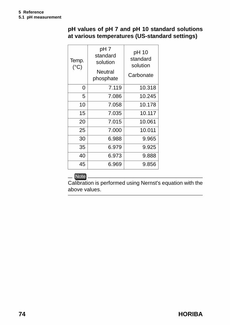
pH values of pH 7 and pH 10 standard solutions at various temperatures (US-standard settings)
Calibration is performed using Nernst's equation with the above values.
Temp. (°C)
pH 7 standard solution
Neutral phosphate
pH 10 standard solution
Carbonate
0 7.119 10.3185 7.086 10.245
10 7.058 10.17815 7.035 10.11720 7.015 10.06125 7.000 10.01130 6.988 9.96535 6.979 9.92540 6.973 9.88845 6.969 9.856
5 Reference 5.1 pH measurement
D-51 75
Using standard solutionsStandard solutions are used to calibrate the scale of the pH meter employed to measure the unknown pH of a solution. Standard solutions of pH 4, 7, and 9 are used in combination according to the particular conditions of the solution that is to be inspected.
When the approximate pH value is desired (1- point calibration)Use the pH 7 standard solution or a standard solution that approximates the pH value of the solution that is to be inspected.
When it is known beforehand whether the test solution is acidic or alkaline (2-point calibration)Acidic: Use the pH 4 and 7 standard solutions.Alkaline: Use the pH 7 and 9 standard solutions.
When an unknown solution is to be inspected (3- point calibration)Use the pH 4, 7, and 9 standard solutions.
OtherWhen finding the pH of other solutions, perform 2-point or 3-point calibration using pH 2, 4, 7, 9, or 12 standard solutions randomly, then measure the test solution.

5 Reference 5.2 Specifications
76 HORIBA
5.2 Specifications
Measurement target
Items in common among meter models
Target Item Description
pH
Measurement principle
Glass electrode
Display range pH -2.00 – 16.00Measurement range
pH 0.00 – 14.00
Resolution 0.01 pHRepeatability ±0.01 pH ±1digit
Temp.
Measurement principle
Thermistor
Measurementrange
0.0 – 100.0 ºC
Resolution 0.1 ºCRepeatability ±0.1 ºC ±1digit
Data memory capacity
Max. 300 pieces of data
Power Dry cell batteries type:AA alkaline with automatic power OFF function
Ambient temperature
0 – 45 ºC
Dimensions 170(H) × 80(W) × 40(D) mmMass of main unit (including batteries)
300 g

5 Reference 5.3 Default settings
D-51 77
5.3 Default settings
Category Item Default values
Commonsetting
Temperature compensation
Automatic temperature compensation
Manual temperature compensation
25 ºC
Automatic power OFF Approx. 30 min (ON)
pH Standard calibration solution
NIST
Calibration setting Asymmetric potential: 0mVSensitivity: 100%
5 Reference 5.4 Operation flowcharts
78 HORIBA
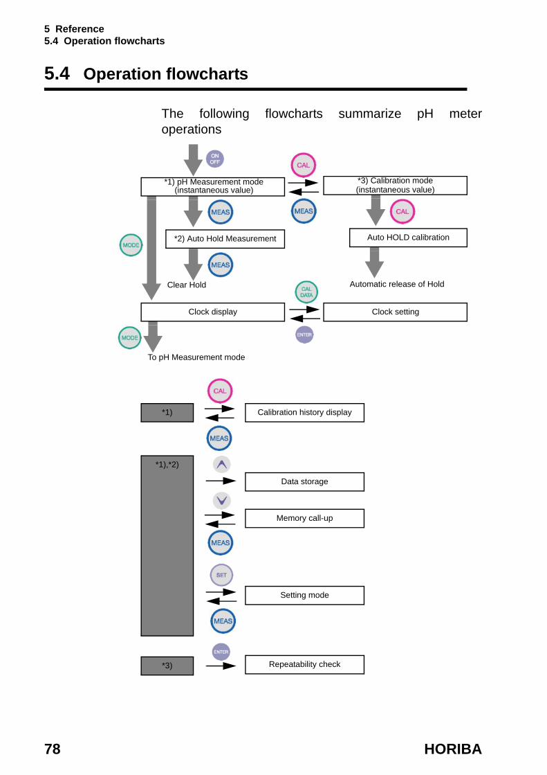
5.4 Operation flowcharts
The following flowcharts summarize pH meter operations
*1) pH Measurement mode (instantaneous value)
Clear Hold Automatic release of Hold
Clock setting
To pH Measurement mode
*3) Calibration mode (instantaneous value)
*2) Auto Hold Measurement Auto HOLD calibration
Clock settingClock display
Calibration history display*1)
*1),*2)
Data storage
Memory call-up
Setting mode
*3) Repeatability check

5 Reference 5.5 Spare and optional parts
D-51 79
5.5 Spare and optional parts
This section lists spare and optional parts for the pH meter.These parts are available through HORIBA distributors. Place an order specifying their name, model, and part number.
5.5.1 Spare parts list
pH electrode (with built-in temperature sensor)
pH electrode (without built-in temperature sensor)
Part name Model Part number Remarks
D-50 series standard electrode
9621-10D 9096001700 Plastic-body electrode (for immersion measurement)
F-50 series standard electrode
9611-10D 9096001800 Glass-body electrode (reinforced responsive glass)
Laboratory-use electrode for slurry samples
9677-10D 9096002000 Built-in washable reference electrode (reinforced responsive glass)
Laboratory-use electrode for micro samples
9669-10D 9096001900 Electrode incorporating temperature sensor compatible with micro sample measurementTip: φ3, 55 mm
Part name Model Part number Remarks
Low-end electrode
6066-10C 9003013400 Glass-body electrode
Electrode for NMR tubes
6069-10C 9003013500 Tip: φ3, 180 mm
5 Reference 5.5 Spare and optional parts
80 HORIBA
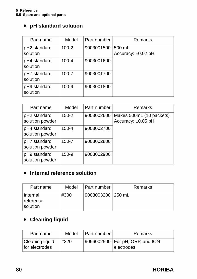
pH standard solution
Internal reference solution
Cleaning liquid
Part name Model Part number Remarks
pH2 standard solution
100-2 9003001500 500 mL Accuracy: ±0.02 pH
pH4 standard solution
100-4 9003001600
pH7 standard solution
100-7 9003001700
pH9 standard solution
100-9 9003001800
Part name Model Part number Remarks
pH2 standard solution powder
150-2 9003002600 Makes 500mL (10 packets)Accuracy: ±0.05 pH
pH4 standard solution powder
150-4 9003002700
pH7 standard solution powder
150-7 9003002800
pH9 standard solution powder
150-9 9003002900
Part name Model Part number Remarks
Internal reference solution
#300 9003003200 250 mL
Part name Model Part number Remarks
Cleaning liquid for electrodes
#220 9096002500 For pH, ORP, and ION electrodes
5 Reference 5.5 Spare and optional parts
D-51 81
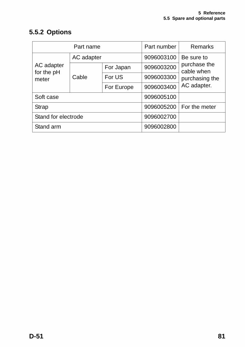
5.5.2 Options
Part name Part number Remarks
AC adapter for the pH meter
AC adapter 9096003100 Be sure to purchase the cable when purchasing the AC adapter.
Cable
For Japan 9096003200
For US 9096003300
For Europe 9096003400
Soft case 9096005100
Strap 9096005200 For the meter
Stand for electrode 9096002700
Stand arm 9096002800

For any question regarding this product, please contact your local agency, or inquire from the Customer Registration website (www.horiba.co.jp/register)
First edition:August 2003CODE:I1001377000
Recommended