CS 450: COMPUTER GRAPHICS
VISIBLE SURFACE DETECTIONSPRING 2016
DR. MICHAEL J. REALE

INTRODUCTION
• We’ve talked about drawing surfaces, but what happens when a surface is hidden?
• E.g., at the back of an object, obscured by another surface, etc.
• We need to determine which surfaces (or parts of surfaces) are visible
• Two general categories (which sometimes overlap):
• Object-space approaches deal with objects/primitives themselves
• Image-space approaches deal with projected primitives at pixel level

OVERVIEW
• In this slide deck, we will cover the following approaches:
• Back-face detection
• Depth-buffer/Z-buffer
• A-buffer
• BSP trees
• Octrees
• Ray-casting

BACK-FACE DETECTION
BACK-FACE CULLING
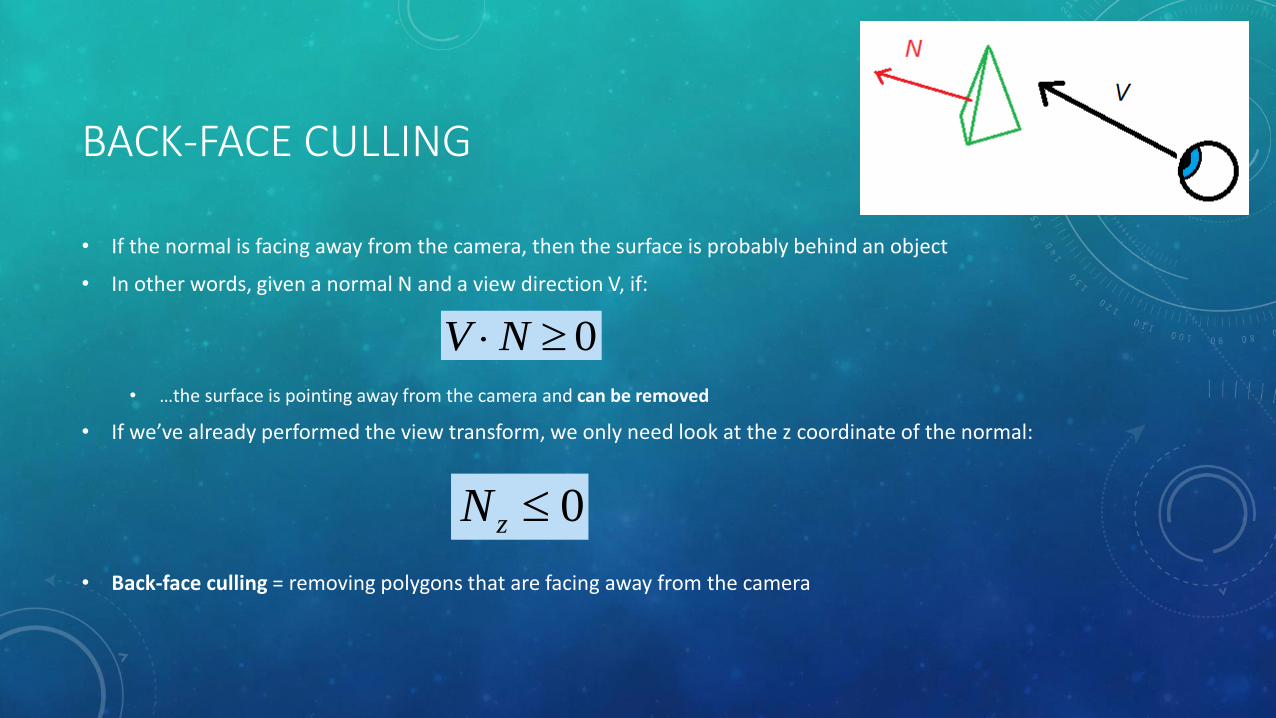
• If the normal is facing away from the camera, then the surface is probably behind an object
• In other words, given a normal N and a view direction V, if:
• …the surface is pointing away from the camera and can be removed
• If we’ve already performed the view transform, we only need look at the z coordinate of the normal:
• Back-face culling = removing polygons that are facing away from the camera
0NV
0zN

BACK-FACE CULLING
• All non-overlapping, convex shapes done!
• Concave shapes may obscure themselves more work to do
• Overlapping shapes (convex or concave) still more work to do
• However, it is always a good preprocessing step to other approaches generally cuts the total number of polygons to render in half
OPENGL FACE CULLING
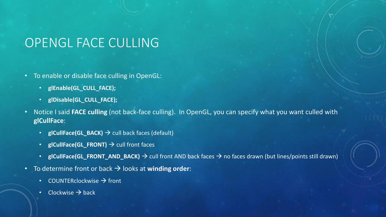
• To enable or disable face culling in OpenGL:
• glEnable(GL_CULL_FACE);
• glDisable(GL_CULL_FACE);
• Notice I said FACE culling (not back-face culling). In OpenGL, you can specify what you want culled with glCullFace:
• glCullFace(GL_BACK) cull back faces (default)
• glCullFace(GL_FRONT) cull front faces
• glCullFace(GL_FRONT_AND_BACK) cull front AND back faces no faces drawn (but lines/points still drawn)
• To determine front or back looks at winding order:
• COUNTERclockwise front
• Clockwise back

DEPTH-BUFFER/Z-BUFFER

DEPTH-BUFFER/Z-BUFFER
• Depth-buffer/Z-buffer approach
• Pretty much the standard for depth sorting in almost all applications
• Implemented in graphics hardware
• Have depth buffer = separate buffer that holds depth values
• Initialize to 1.0 (remember: normalized device coordinates)
• If projected pixel z < depth[x,y]:
• Depth[x,y] = z
• Color[x,y] = pixel’s color
• Otherwise, ignore pixel

DEPTH-BUFFER/Z-BUFFER

DEPTH-BUFFER/Z-BUFFER
• Advantages:
• Very easy to implement
• For opaque surfaces, does not matter what order they are rendered in!
• Disadvantages:
• Does not work properly with transparent or semi-transparent surfaces (if drawn out of order)
• Can be a little inefficient might already have nearest pixel, but still have to check every other overlapping polygon on that pixel

DEPTH-BUFFER/Z-BUFFER IN OPENGL
• To enable/disable depth-buffer/z-buffer testing in OpenGL:
• glEnable(GL_DEPTH_TEST);
• glDisable(GL_DEPTH_TEST);
• You can also set how the z-buffer works with glDepthFunc()
• When clearing your color buffer, you should also clear out your depth buffer:
• glClear(GL_COLOR_BUFFER_BIT | GL_DEPTH_BUFFER_BIT);

A-BUFFER
A-BUFFER
• A-buffer
• Extension of z-buffer BUT holds MULTIPLE fragments per pixel (unlike a z-buffer)
• The “A” can stand for: anti-aliased, area-averaged, accumulation
• Developed at Lucasfilm Studios as part of their surface rendering system REYES (“Renders Everything You Ever Saw”)
• Used for:
• Depth sorting
• Transparency
• Anti-aliasing
• Mostly implemented as part of software rendered, BUT can be implemented in shaders with some limitations
http://brad-ricca.com/wp-content/uploads/2014/04/lucasfilm_logocap1.jpg
A-BUFFER: FRAGMENTS AND PIXELS
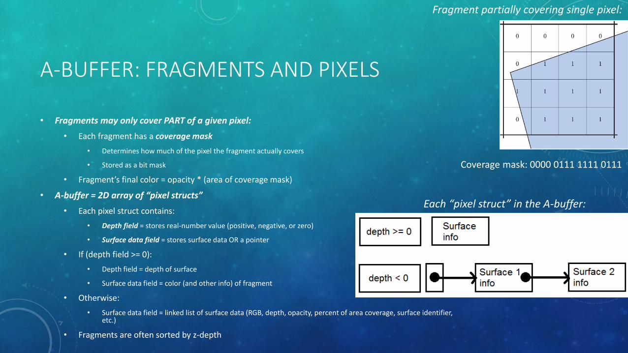
• Fragments may only cover PART of a given pixel:
• Each fragment has a coverage mask
• Determines how much of the pixel the fragment actually covers
• Stored as a bit mask
• Fragment’s final color = opacity * (area of coverage mask)
• A-buffer = 2D array of “pixel structs”
• Each pixel struct contains:
• Depth field = stores real-number value (positive, negative, or zero)
• Surface data field = stores surface data OR a pointer
• If (depth field >= 0):
• Depth field = depth of surface
• Surface data field = color (and other info) of fragment
• Otherwise:
• Surface data field = linked list of surface data (RGB, depth, opacity, percent of area coverage, surface identifier, etc.)
• Fragments are often sorted by z-depth
Coverage mask: 0000 0111 1111 0111
Each “pixel struct” in the A-buffer:
Fragment partially covering single pixel:

A-BUFFER: MERGING
• At some point, the list of fragments needs to be merged to get the final color:
• Each fragment determine “inside” and “outside” parts of coverage mask
• Recursively blend list of fragments in these areas
• When merging occurs often tied to how fragments are stored:
• Variable size list
• Can wait until final shading step to merge
• Harder to implement this in hardware/shaders often using software renderer
• Fixed size list
• Can use hardware/shaders (e.g., writing to a texture, using existing z-buffer)
• However, there isn’t really an upper bound on how many fragments overlap a pixel! merge when list is full of fragments (Z3 algorithm)

A-BUFFER VS. OPENGL ACCUMULATION BUFFER
• The buffer used for the A-buffer approach is called an accumulation buffer
• This is NOT to be confused with accumulation buffers in OpenGL, which are implemented as a buffer with a SINGLE color value per pixel
• Do not draw directly into; copy/add whole color buffer into it
• Use glAccum(GLenum op, GLfloat value); values of op:
• GL_ACCUM = read from color buffer, multiply by value, and add to accumulation buffer
• GL_LOAD = same as GL_ACCUM, except it REPLACES the values in the accumulation buffer
• GL_RETURN = takes values from the accumulation buffer, multiplies them by value, and places the result in the color buffer(s) enabled for writing.
• GL_ADD /GL_MULT = simply add or multiply the value of each pixel in the accumulation buffer by value and then return it to the accumulation buffer. For GL_MULT, value is clamped to be in the range [-1.0,1.0]. For GL_ADD, no clamping occurs.
• Can be used for anti-aliasing and motion blur

BSP TREES

BSP TREES
• BSP Trees = Binary Space Partitioning Trees
• Used for depth sorting objects
• Also used for collision detection and intersection calculations (e.g., for ray tracing)
• Two varieties: axis-aligned and polygon-aligned
• Basic idea:
• Use plane to divide space in two
• Sort geometry into these two spaces
• Repeat process recursively
• Traverse trees in a certain way contents sorted from front-to-back from any point of view
• Sorting approximate for axis-aligned and exact for polygon-aligned BSPs
AXIS-ALIGNED BSP TREES
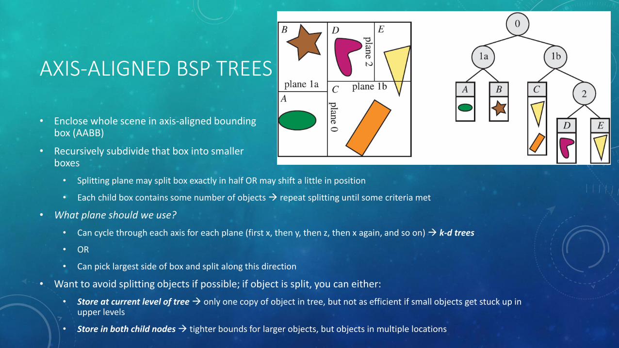
• Enclose whole scene in axis-aligned bounding box (AABB)
• Recursively subdivide that box into smaller boxes
• Splitting plane may split box exactly in half OR may shift a little in position
• Each child box contains some number of objects repeat splitting until some criteria met
• What plane should we use?
• Can cycle through each axis for each plane (first x, then y, then z, then x again, and so on) k-d trees
• OR
• Can pick largest side of box and split along this direction
• Want to avoid splitting objects if possible; if object is split, you can either:
• Store at current level of tree only one copy of object in tree, but not as efficient if small objects get stuck up in upper levels
• Store in both child nodes tighter bounds for larger objects, but objects in multiple locations

AXIS-ALIGNED BSP TREES
• To traverse tree:
• Start at root node
• Recursively pick branch on same side as viewer
• When you reach the bottom, go back and do other side of tree
• Effectively a depth-first traversal
• Not EXACTLY sorted front-to-back, since:
• Contents of leaf nodes may not be sorted themselves
• Objects may be in multiple nodes of the tree, depending on how splitting is done

POLYGON-ALIGNED BSP TREES
• Particularly useful for rendering static/rigid geometry in an exact sorted order
• Popular for games like Doom, back when there was no hardware Z-buffer
• Still used for collision detection
• Polygons = dividing planes
• Start with one polygon as root
• Divide all other polygons into inside and outside plane of polygon
• If other polygon intersects plane split polygon
• Choose another polygon in each half-space as divider
• Repeat process recursively until all polygons in BSP tree
• Time-consuming process usually create tree once and store for further use
http://vignette2.wikia.nocookie.net/doom/images/b/b3/Imp.png/revision/latest/scale-to-width/256?cb=20050113171050

POLYGON-ALIGNED BSP TREES
• Challenge: ideally want balanced BSP tree i.e., depth of all branches is the same
• Useful property: for a given view, tree can be traversed in strictly back to front (or front to back) order
• Determine on which side the root plane the camera is located
• Go down branch on other side of camera
• Repeat process recursively
• Go back up to other branches when hit bottom
POLYGON-ALIGNED BSP TREES
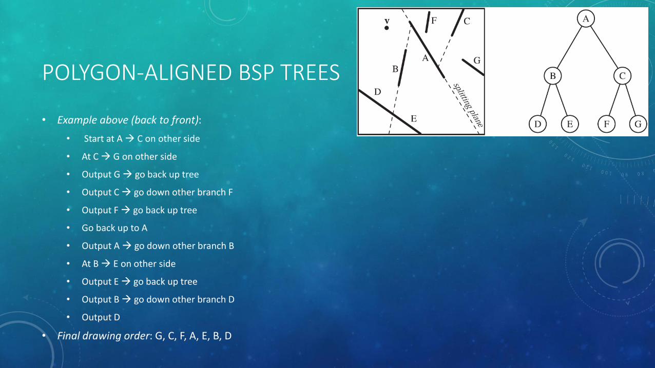
• Example above (back to front):
• Start at A C on other side
• At C G on other side
• Output G go back up tree
• Output C go down other branch F
• Output F go back up tree
• Go back up to A
• Output A go down other branch B
• At B E on other side
• Output E go back up tree
• Output B go down other branch D
• Output D
• Final drawing order: G, C, F, A, E, B, D

OCTREES
OCTREES
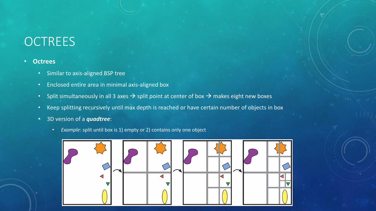
• Octrees
• Similar to axis-aligned BSP tree
• Enclosed entire area in minimal axis-aligned box
• Split simultaneously in all 3 axes split point at center of box makes eight new boxes
• Keep splitting recursively until max depth is reached or have certain number of objects in box
• 3D version of a quadtree:
• Example: split until box is 1) empty or 2) contains only one object
OCTREES
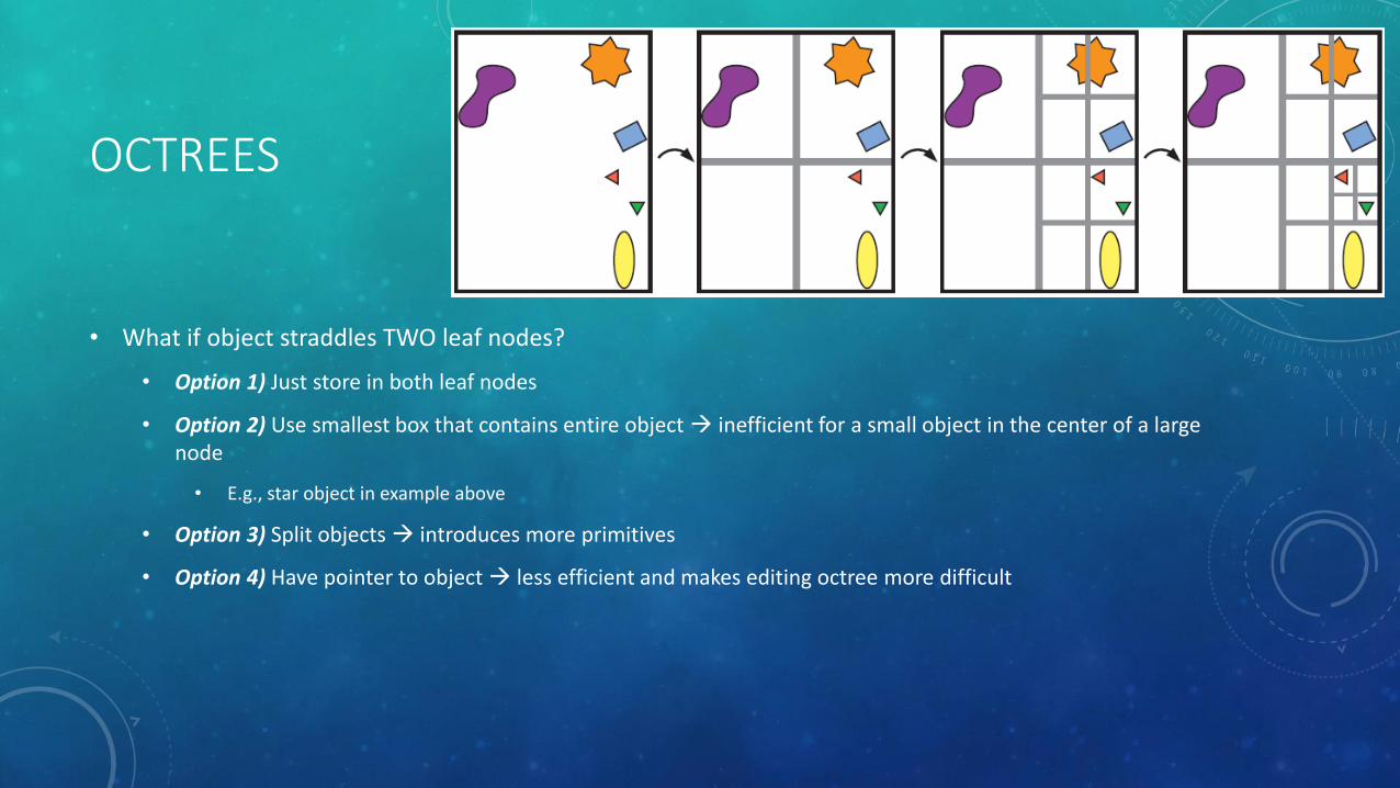
• What if object straddles TWO leaf nodes?
• Option 1) Just store in both leaf nodes
• Option 2) Use smallest box that contains entire object inefficient for a small object in the center of a large node
• E.g., star object in example above
• Option 3) Split objects introduces more primitives
• Option 4) Have pointer to object less efficient and makes editing octree more difficult
OCTREES VS. BSP TREES
• BSP tree can partition things the same way as an octree
• Octree doesn’t need to store additional plane information like BSP trees
• BSP trees can be more efficient because of better splitting

RAY-CASTING

RAY-CASTING
• Ray-casting = shooting a ray from the camera through each position in the projection plane and checking what object(s) we intersect with nearest one is used as color for a pixel
• Alternative (non-real-time) rendering approach
• Works with polygonal objects as well as implicit objects (e.g., F(x,y,z) = 0)
• Must intersect ray with ALL objects in scene and pick nearest point inefficient
• Partial solution: use BSP trees or similar approaches to reduce intersection computations

RAY-CASTING VS. RAY-TRACING
• Ray-casting = shooting ray to nearest object; special case of ray-tracing
• Ray-tracing = traces multiple ray paths to get global reflection, refraction, etc.
Recommended


![[XLS] · Web view450. 90. 450. 900. 900. 225. 450. 450. 900. 450. 225. 270. 4.5. 450. 450. 450. 450. 450. 450. 450. 450. 450. 900. 450. 450. 450. 112.5. 900. 900. 450. 112.5. 450](https://img.dokumen.tips/doc/110x75/5b3c17127f8b9a213f8d0b42/xls-web-view450-90-450-900-900-225-450-450-900-450-225-270-45.jpg)