S7-300 Instruction List
CPU 31xC, CPU 31x, IM 151-7 CPU, BM 147-1 CPU, BM 147-2 CPU
This Instruction List has the order number:
6ES7398-8AA10-8BN0
Edition 06/2003A5E00105517-03

We have checked the contents of this manual for agreement with thehardware and software described. Since deviations cannot be pre-cluded entirely, we cannot guarantee full agreement. However, thedata in this manual are reviewed regularly and any necessary cor-rections included in subsequent editions. Suggestions for improve-ment are welcomed.
Disclaim of LiabilityCopyright � Siemens AG 2001 – 2003 All rights reserved
The reproduction, transmission or use of this document or itscontents is not permitted without express written authority.Offenders will be liable for damages. All rights, including rightscreated by patent grant or registration of a utility model or design, arereserved.
Siemens AGBereich Automation and DrivesGeschaeftsgebiet Industrial Automatiuon SystemsPostfach 4848, D- 90327 Nuernberg
Siemens AG 2001 – 2003Technical data subject to change.
Siemens Aktiengesellschaft 6ES7398-8AA10-8BN0
Contents
1S7-300 Instruction list, CPU 31xC, CPU 31x, IM 151-7 CPU, BM 147-1 CPU, BM 147-2 CPU A5E00105517-03
Contents
Validity Range of the Instructions List 5. . . . . . . . . . . . . . . . . . . . . . . . . . . . . . . . . . . . . . . . . . . . . . . . . . . . . . . . .
Address Identifiers and Parameter Ranges 6. . . . . . . . . . . . . . . . . . . . . . . . . . . . . . . . . . . . . . . . . . . . . . . . . . . .
Abbreviations and Mnemonics 11. . . . . . . . . . . . . . . . . . . . . . . . . . . . . . . . . . . . . . . . . . . . . . . . . . . . . . . . . . . . . .
Registers 13. . . . . . . . . . . . . . . . . . . . . . . . . . . . . . . . . . . . . . . . . . . . . . . . . . . . . . . . . . . . . . . . . . . . . . . . . . . . . . . . .
Examples of Addressing 16. . . . . . . . . . . . . . . . . . . . . . . . . . . . . . . . . . . . . . . . . . . . . . . . . . . . . . . . . . . . . . . . . . . .
Examples of how to calculate the pointer 19. . . . . . . . . . . . . . . . . . . . . . . . . . . . . . . . . . . . . . . . . . . . . . . . . . . . .
Execution Times with Indirect Addressing 20. . . . . . . . . . . . . . . . . . . . . . . . . . . . . . . . . . . . . . . . . . . . . . . . . . . . .
Calculating the Execution Time Using a CPU 314C-2 DP as an Example 22. . . . . . . . . . . . . . . . . . . . . . . . . .
List of Instructions 27. . . . . . . . . . . . . . . . . . . . . . . . . . . . . . . . . . . . . . . . . . . . . . . . . . . . . . . . . . . . . . . . . . . . . . . . .
Bit Logic Instructions 28. . . . . . . . . . . . . . . . . . . . . . . . . . . . . . . . . . . . . . . . . . . . . . . . . . . . . . . . . . . . . . . . .
Bit Logic Instructions with Parenthetical Expressions 34. . . . . . . . . . . . . . . . . . . . . . . . . . . . . . . . . . . . .
ORing of AND Operations 36. . . . . . . . . . . . . . . . . . . . . . . . . . . . . . . . . . . . . . . . . . . . . . . . . . . . . . . . . . . .
Logic Instructions with Timers and Counters 37. . . . . . . . . . . . . . . . . . . . . . . . . . . . . . . . . . . . . . . . . . . . .
Word Logic Instructions with the Contents of Accumulator 1 41. . . . . . . . . . . . . . . . . . . . . . . . . . . . . . .
Evaluating Conditions Using AND, OR and EXCLUSIVE OR 43. . . . . . . . . . . . . . . . . . . . . . . . . . . . . . .
Edge-Triggered Instructions 45. . . . . . . . . . . . . . . . . . . . . . . . . . . . . . . . . . . . . . . . . . . . . . . . . . . . . . . . . . .

Contents
2S7-300 Instruction list, CPU 31xC, CPU 31x, IM 151-7 CPU, BM 147-1 CPU, BM 147-2 CPU A5E00105517-03
Setting/Resetting Bit Addresses 48. . . . . . . . . . . . . . . . . . . . . . . . . . . . . . . . . . . . . . . . . . . . . . . . . . . . . . .
Instructions Directly Affecting the RLO 51. . . . . . . . . . . . . . . . . . . . . . . . . . . . . . . . . . . . . . . . . . . . . . . . . .
Timer Instructions 53. . . . . . . . . . . . . . . . . . . . . . . . . . . . . . . . . . . . . . . . . . . . . . . . . . . . . . . . . . . . . . . . . . . .
Counter Instructions 55. . . . . . . . . . . . . . . . . . . . . . . . . . . . . . . . . . . . . . . . . . . . . . . . . . . . . . . . . . . . . . . . . .
Load Instructions 57. . . . . . . . . . . . . . . . . . . . . . . . . . . . . . . . . . . . . . . . . . . . . . . . . . . . . . . . . . . . . . . . . . . .
Load Instructions for Timers and Counters 62. . . . . . . . . . . . . . . . . . . . . . . . . . . . . . . . . . . . . . . . . . . . . .
Transfer Instructions 63. . . . . . . . . . . . . . . . . . . . . . . . . . . . . . . . . . . . . . . . . . . . . . . . . . . . . . . . . . . . . . . . .
Load and Transfer Instructions for Address Registers 70. . . . . . . . . . . . . . . . . . . . . . . . . . . . . . . . . . . . .
Load and Transfer Instructions for the Status Word 72. . . . . . . . . . . . . . . . . . . . . . . . . . . . . . . . . . . . . . .
Load Instructions for DB Number and DB Length 73. . . . . . . . . . . . . . . . . . . . . . . . . . . . . . . . . . . . . . . . .
Integer Math (16 Bits) 74. . . . . . . . . . . . . . . . . . . . . . . . . . . . . . . . . . . . . . . . . . . . . . . . . . . . . . . . . . . . . . . .
Integer Math (32 Bits) 75. . . . . . . . . . . . . . . . . . . . . . . . . . . . . . . . . . . . . . . . . . . . . . . . . . . . . . . . . . . . . . . .
Floating-Point Math (32 Bits) 76. . . . . . . . . . . . . . . . . . . . . . . . . . . . . . . . . . . . . . . . . . . . . . . . . . . . . . . . . .
Square Root and Square Instructions (32 Bits) 78. . . . . . . . . . . . . . . . . . . . . . . . . . . . . . . . . . . . . . . . . . .
Logarithmic Function (32 Bits) 79. . . . . . . . . . . . . . . . . . . . . . . . . . . . . . . . . . . . . . . . . . . . . . . . . . . . . . . . .
Trigonometrical Functions (32 Bits) 80. . . . . . . . . . . . . . . . . . . . . . . . . . . . . . . . . . . . . . . . . . . . . . . . . . . . .
Adding Constants 81. . . . . . . . . . . . . . . . . . . . . . . . . . . . . . . . . . . . . . . . . . . . . . . . . . . . . . . . . . . . . . . . . . . .

Contents
3S7-300 Instruction list, CPU 31xC, CPU 31x, IM 151-7 CPU, BM 147-1 CPU, BM 147-2 CPU A5E00105517-03
Adding Using Address Registers 82. . . . . . . . . . . . . . . . . . . . . . . . . . . . . . . . . . . . . . . . . . . . . . . . . . . . . . .
Comparison Instructions with Integers (16 Bits) 83. . . . . . . . . . . . . . . . . . . . . . . . . . . . . . . . . . . . . . . . . .
Comparison Instructions with Integers (32 Bits) 84. . . . . . . . . . . . . . . . . . . . . . . . . . . . . . . . . . . . . . . . . .
Comparison Instructions with Real Numbers (32 Bits) 85. . . . . . . . . . . . . . . . . . . . . . . . . . . . . . . . . . . . .
Shift Instructions 86. . . . . . . . . . . . . . . . . . . . . . . . . . . . . . . . . . . . . . . . . . . . . . . . . . . . . . . . . . . . . . . . . . . . .
Rotate Instructions 88. . . . . . . . . . . . . . . . . . . . . . . . . . . . . . . . . . . . . . . . . . . . . . . . . . . . . . . . . . . . . . . . . . .
Accumulator Transfer Instructions, Incrementing and Decrementing 89. . . . . . . . . . . . . . . . . . . . . . . .
Program Display and Null Operation Instructions 90. . . . . . . . . . . . . . . . . . . . . . . . . . . . . . . . . . . . . . . . .
Data Type Conversion Instructions 91. . . . . . . . . . . . . . . . . . . . . . . . . . . . . . . . . . . . . . . . . . . . . . . . . . . . .
Forming the Ones and Twos Complements 93. . . . . . . . . . . . . . . . . . . . . . . . . . . . . . . . . . . . . . . . . . . . . .
Block Call Instructions 94. . . . . . . . . . . . . . . . . . . . . . . . . . . . . . . . . . . . . . . . . . . . . . . . . . . . . . . . . . . . . . . .
Block End Instructions 96. . . . . . . . . . . . . . . . . . . . . . . . . . . . . . . . . . . . . . . . . . . . . . . . . . . . . . . . . . . . . . . .
Exchanging Shared Data Block and Instance Data Block 97. . . . . . . . . . . . . . . . . . . . . . . . . . . . . . . . . .
Jump Instructions 98. . . . . . . . . . . . . . . . . . . . . . . . . . . . . . . . . . . . . . . . . . . . . . . . . . . . . . . . . . . . . . . . . . . .
Instructions for the Master Control Relay (MCR) 102. . . . . . . . . . . . . . . . . . . . . . . . . . . . . . . . . . . . . . . .

Contents
4S7-300 Instruction list, CPU 31xC, CPU 31x, IM 151-7 CPU, BM 147-1 CPU, BM 147-2 CPU A5E00105517-03
Organisation Blocks (OB) 103. . . . . . . . . . . . . . . . . . . . . . . . . . . . . . . . . . . . . . . . . . . . . . . . . . . . . . . . . . . . . . . . . .
Function Blocks (FB) 109. . . . . . . . . . . . . . . . . . . . . . . . . . . . . . . . . . . . . . . . . . . . . . . . . . . . . . . . . . . . . . . . . . . . .
Functions (FC) 109. . . . . . . . . . . . . . . . . . . . . . . . . . . . . . . . . . . . . . . . . . . . . . . . . . . . . . . . . . . . . . . . . . . . . . . . . . .
Data Blocks 110. . . . . . . . . . . . . . . . . . . . . . . . . . . . . . . . . . . . . . . . . . . . . . . . . . . . . . . . . . . . . . . . . . . . . . . . . . . . .
Memory required by the SFBs for the integrated inputs and outputs 111. . . . . . . . . . . . . . . . . . . . . . . . . . . . .
System Functions (SFC) 112. . . . . . . . . . . . . . . . . . . . . . . . . . . . . . . . . . . . . . . . . . . . . . . . . . . . . . . . . . . . . . . . . .
System Function Blocks (SFB) 118. . . . . . . . . . . . . . . . . . . . . . . . . . . . . . . . . . . . . . . . . . . . . . . . . . . . . . . . . . . . .
IEC Functions 123. . . . . . . . . . . . . . . . . . . . . . . . . . . . . . . . . . . . . . . . . . . . . . . . . . . . . . . . . . . . . . . . . . . . . . . . . . .
System Status Sublist 127. . . . . . . . . . . . . . . . . . . . . . . . . . . . . . . . . . . . . . . . . . . . . . . . . . . . . . . . . . . . . . . . . . . . .
PROFIBUS-DP Sublists 133. . . . . . . . . . . . . . . . . . . . . . . . . . . . . . . . . . . . . . . . . . . . . . . . . . . . . . . . . . . . . . . . . . .
Alphabetical Index of Instructions 135. . . . . . . . . . . . . . . . . . . . . . . . . . . . . . . . . . . . . . . . . . . . . . . . . . . . . . . . . . .

Validity Range of the Instructions List
5S7-300 Instruction list, CPU 31xC, CPU 31x, IM 151-7 CPU, BM 147-1 CPU, BM 147-2 CPU A5E00105517-03
Validity Range of the Instructions List
CPU As of order no.
As of Version In the following referred to as
Firmware Hardware
CPU 312 6ES7312-1AD10-0AB0 V2.0.0 01 312
CPU 312C 6ES7312-5BD01-0AB0
CPU 313C 6ES7313-5BE01-0AB0 V2.0.0 01 31x
CPU 313C-2 PtP 6ES7313-6BE01-0AB0
CPU 313C-2 DP 6ES7313-6CE01-0AB0
CPU 314 6ES7314-1AF10-0AB0
CPU 314C-2 PtP 6ES7314-6BF01-0AB0
CPU 314C-2 DP 6ES7314-6CF01-0AB0
CPU 315–2 DP 6ES7315-2AG10-0AB0
CPU 317-2 DP 6ES7 317-2AJ10-0AB0 V2.1.0 01 317
BM 147-1 CPU 6ES7 147-1AA10-0AB0 V2.1.0 01 147
BM 147-2 CPU 6ES7 147-2AA00-0XB0
IM 151-7 CPU 6ES7 151-7AA10-0AB0 V2.1.0 01 151

Address Identifiers and Parameter Ranges
6S7-300 Instruction list, CPU 31xC, CPU 31x, IM 151-7 CPU, BM 147-1 CPU, BM 147-2 CPU A5E00105517-03
Address Identifiers and Parameter Ranges
Addr IDParameter Ranges
DescriptionAddr. ID31x 147 151 317
Description31x, 147, 151 317
p
Q 0.0 to 127.7 0.0 to 255.7 Output (in PIQ)
QB 0 to 127 0 to 255 Output byte (in PIQ)
QW 0 to 126 0 to 254 Output word (in PIQ)
QD 0 to 124 0 to 252 Output double word (in PIQ)

Address Identifiers and Parameter Ranges
7S7-300 Instruction list, CPU 31xC, CPU 31x, IM 151-7 CPU, BM 147-1 CPU, BM 147-2 CPU A5E00105517-03
Parameter RangesParameter Ranges
Addr. ID CPU 31xC, 312, 314, 147,151
315-2 DP 317Description
DBX 0.0 to 16383.7 0.0 to 16383.7 0.0 to 65535.7 Data bit in data block
DB 1 to 511 1 to 1023 1 to 2047 Data block
DBB 0 to 16383 0 to 16383 0 to 65535 Data byte in DB
DBW 0 to 16382 0 to 16382 0 to 65534 Data word in DB
DBD 0 to 16380 0 to 16380 0 to 65532 Data double word in DB
DIX 0.0 to 16383.7 0.0 to 16383.7 0.0 to 65535.7 Data bit in instance DB
DI 1 to 511 1 to 1023 1 to 2047 Instance data block
DIB 0 to 16383 0 to 16383 0 to 65535 Data byte in instance DB
DIW 0 to 16382 0 to 16382 0 to 65534 Data word in instance DB
DID 0 to 16380 0 to 16380 0 to 65532 Data double word in instance DB

Address Identifiers and Parameter Ranges
8S7-300 Instruction list, CPU 31xC, CPU 31x, IM 151-7 CPU, BM 147-1 CPU, BM 147-2 CPU A5E00105517-03
Addr IDParameter Ranges
DescriptionAddr. ID312 31x, 147, 151 317
Description
I 0.0 to 127.7 0.0 to 127.7 0.0 to 255.7 Inputs (in PII)
IB 0 to 127 0 to 127 0 to 255 Input byte (in PII)
IW 0 to 126 0 to 126 0 to 254 Input word (in PII)
ID 0 to 124 0 to 124 0 to 252 Input double word (in PII)
Parameter Ranges
Addr. ID 312 313C, 314, 314C,147, 151
315-2 DP 1)317
Description
L 0.0 to 255.7 0.0 to 509.7 0.0 to 509.7 0.0 to 1023.7 Local data bit
LB 0 to 255 0 to 509 0 to 509 0 to 1023 Local data byte
LW 0 to 254 0 to 508 0 to 508 0 to 1022 Local data word
LD 0 to 252 0 to 506 0 to 506 0 to 1020 Local data double word
1) CPU 315-2 DP has a max. of 1024 bytes for each run level, but only a max. of 510 bytes of local data per block.
Address Identifiers and Parameter Ranges
9S7-300 Instruction list, CPU 31xC, CPU 31x, IM 151-7 CPU, BM 147-1 CPU, BM 147-2 CPU A5E00105517-03
Parameter RangesD i tiAddr. ID 312 313C, 314, 314C,
147, 151315-2 DP 317 Description
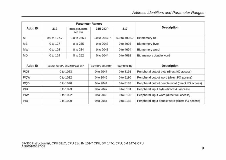
M 0.0 to 127.7 0.0 to 255.7 0.0 to 2047.7 0.0 to 4095.7 Bit memory bit
MB 0 to 127 0 to 255 0 to 2047 0 to 4095 Bit memory byte
MW 0 to 126 0 to 254 0 to 2046 0 to 4094 Bit memory word
MD 0 to 124 0 to 252 0 to 2044 0 to 4092 Bit memory double word
Addr. ID Except for CPU 315-2 DP and 317 Only CPU 315-2 DP Only CPU 317 Description
PQB 0 to 1023 0 to 2047 0 to 8191 Peripheral output byte (direct I/O access)
PQW 0 to 1022 0 to 2046 0 to 8190 Peripheral output word (direct I/O access)
PQD 0 to 1020 0 to 2044 0 to 8188 Peripheral output double word (direct I/O access)
PIB 0 to 1023 0 to 2047 0 to 8181 Peripheral input byte (direct I/O access)
PIW 0 to 1022 0 to 2046 0 to 8190 Peripheral input word (direct I/O access)
PID 0 to 1020 0 to 2044 0 to 8188 Peripheral input double word (direct I/O access)
Address Identifiers and Parameter Ranges
10S7-300 Instruction list, CPU 31xC, CPU 31x, IM 151-7 CPU, BM 147-1 CPU, BM 147-2 CPU A5E00105517-03
Addr IDParameter Ranges
DescriptionAddr. ID312 31x, 147, 151 317
Description
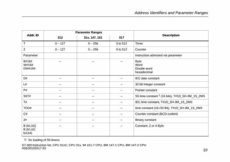
T 0 – 127 0 – 256 0 to 512 Timer
Z 0 – 127 0 – 256 0 to 512 Counter
Parameter Instruction adressed via parameter
B#16#W#16#DW#16#
– – – ByteWordDouble wordhexadecimal
D# – – – IEC date constant
L# – – – 32-bit integer constant
P# – – – Pointer constant
S5T# – – – S5 time constant 1 (16 bits), T#1D_5H-3M_1S_2MS
T# – – – IEC time constant, T#1D_5H-3M_1S_2MS
TOD# – – – time constant (16-/32-Bit), T#1D_5H-3M_1S_2MS
C# – – – Counter constant (BCD-codiert)
2# – – – Binary constant
B (b1,b2) B (b1,b2;b3,b4)
– – – Constant, 2 or 4 Byte
1) for loading of S5 timers

Abbreviations and Mnemonics
11S7-300 Instruction list, CPU 31xC, CPU 31x, IM 151-7 CPU, BM 147-1 CPU, BM 147-2 CPU A5E00105517-03
Abbreviations and Mnemonics
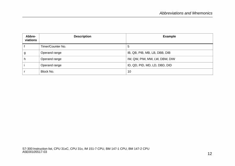
The following abbreviations and mnemonics are used in the Instruction List:
Abbre-viations
Description Example
k8 8-bit constant 32
k16 16-bit constant 631
k32 32-bit constant 1272 5624
i8 8-bit integer –155
i16 16-bit integer +6523
i32 32-bit integer –2 222 222
m P#x.y (pointer) P#240.3
n Binary constant 1001 1100
p Hexadecimal constant EA12
q Real number (32-bit floating-point number) 12.34567E+5
LABEL Symbolic jump address (max. 4 characters) DEST
a Byte address 2
b Bit address x.1
c Operand range I, Q, M, L, DBX, DIX
Abbreviations and Mnemonics
12S7-300 Instruction list, CPU 31xC, CPU 31x, IM 151-7 CPU, BM 147-1 CPU, BM 147-2 CPU A5E00105517-03
Abbre-viations
Description Example
f Timer/Counter No. 5
g Operand range IB, QB, PIB, MB, LB, DBB, DIB
h Operand range IW, QW, PIW, MW, LW, DBW, DIW
i Operand range ID, QD, PID, MD, LD, DBD, DID
r Block No. 10
Registers
13S7-300 Instruction list, CPU 31xC, CPU 31x, IM 151-7 CPU, BM 147-1 CPU, BM 147-2 CPU A5E00105517-03
Registers
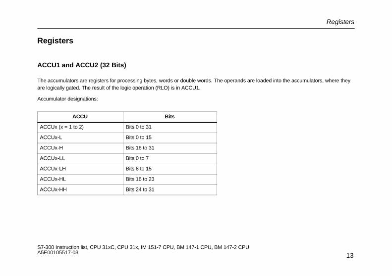
ACCU1 and ACCU2 (32 Bits)
The accumulators are registers for processing bytes, words or double words. The operands are loaded into the accumulators, where theyare logically gated. The result of the logic operation (RLO) is in ACCU1.
Accumulator designations:
ACCU Bits
ACCUx (x = 1 to 2) Bits 0 to 31
ACCUx-L Bits 0 to 15
ACCUx-H Bits 16 to 31
ACCUx-LL Bits 0 to 7
ACCUx-LH Bits 8 to 15
ACCUx-HL Bits 16 to 23
ACCUx-HH Bits 24 to 31
Registers
14S7-300 Instruction list, CPU 31xC, CPU 31x, IM 151-7 CPU, BM 147-1 CPU, BM 147-2 CPU A5E00105517-03
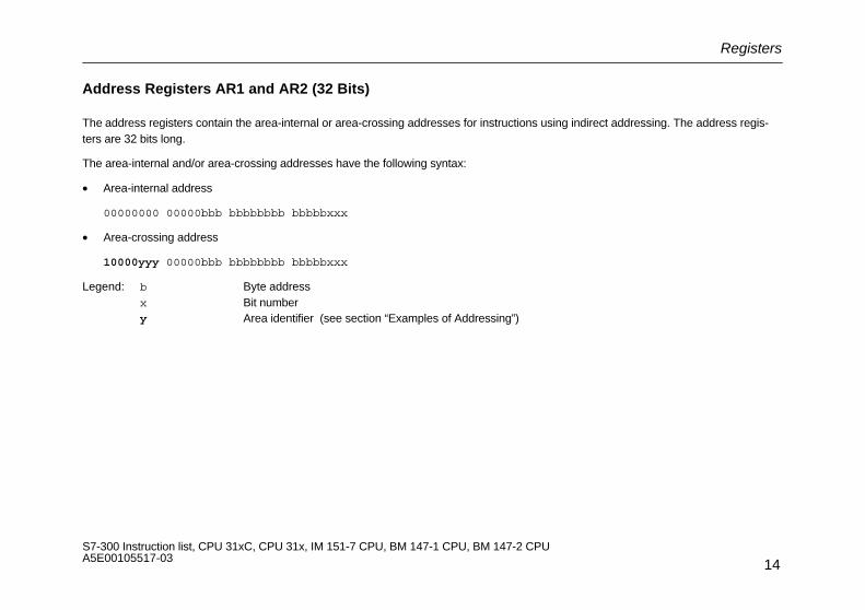
Address Registers AR1 and AR2 (32 Bits)
The address registers contain the area-internal or area-crossing addresses for instructions using indirect addressing. The address regis-ters are 32 bits long.
The area-internal and/or area-crossing addresses have the following syntax:
• Area-internal address
00000000 00000bbb bbbbbbbb bbbbbxxx
• Area-crossing address
10000yyy 00000bbb bbbbbbbb bbbbbxxx
Legend: b Byte addressx Bit numbery Area identifier (see section “Examples of Addressing”)

Registers
15S7-300 Instruction list, CPU 31xC, CPU 31x, IM 151-7 CPU, BM 147-1 CPU, BM 147-2 CPU A5E00105517-03
Status Word (16 Bits)
The status word bits are evaluated or set by the instructions.
The status word is 16 bits long.
Bit Assignment Description
0 FC First check bit , Bit cannot be evaluated in the user program with the L STW instruction since it is not upda-ted at program runtime
1 RLO Result of (previous) logic operation
2 STA Status, Bit cannot be evaluated in the user program with the L STW instruction since it is not updated atprogram runtime
3 OR Or, Bit cannot be evaluated in the user program with the L STW instruction since it is not updated at pro-gram runtime
4 OS Stored overflow
5 OV Overflow
6 CC 0 Condition code
7 CC 1 Condition code
8 BR Binary result
9 ... 15 Unassigned –

Examples of Addressing
16S7-300 Instruction list, CPU 31xC, CPU 31x, IM 151-7 CPU, BM 147-1 CPU, BM 147-2 CPU A5E00105517-03
Examples of Addressing
Addressing Examples Description
Immediate Addressing
L +27 Load 16-bit integer constant “27” into ACCU1
L L#–1 Load 32-bit integer constant “–1” into ACCU1
L 2#1010101010101010 Load binary constant into ACCU1
L DW#16#A0F0_BCFD Load hexadecimal constant into ACCU1
L ’END’ Load ASCII character into ACCU1
L T#500 ms Load time value into ACCU1
L C#100 Load count value into ACCU1
L B#(100,12) Load 2-byte constant
L B#(100,12,50,8) Load 4-byte constant
L P#10.0 Load area-internal pointer into ACCU1
L P#E20.6 Load area-crossing pointer into ACCU1
L –2.5 Load real number into ACCU1
L D#1995–01–20 Load date
L TOD#13:20:33.125 Load time of day
Examples of Addressing
17S7-300 Instruction list, CPU 31xC, CPU 31x, IM 151-7 CPU, BM 147-1 CPU, BM 147-2 CPU A5E00105517-03
Addressing Examples Description
Direct Addressing
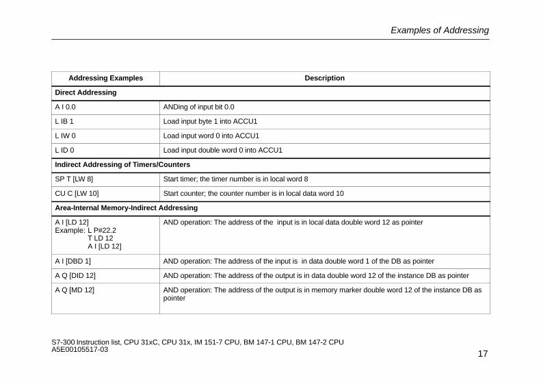
A I 0.0 ANDing of input bit 0.0
L IB 1 Load input byte 1 into ACCU1
L IW 0 Load input word 0 into ACCU1
L ID 0 Load input double word 0 into ACCU1
Indirect Addressing of Timers/Counters
SP T [LW 8] Start timer; the timer number is in local word 8
CU C [LW 10] Start counter; the counter number is in local data word 10
Area-Internal Memory-Indirect Addressing
A I [LD 12]Example: L P#22.2
T LD 12A I [LD 12]
AND operation: The address of the input is in local data double word 12 as pointer
A I [DBD 1] AND operation: The address of the input is in data double word 1 of the DB as pointer
A Q [DID 12] AND operation: The address of the output is in data double word 12 of the instance DB as pointer
A Q [MD 12] AND operation: The address of the output is in memory marker double word 12 of the instance DB aspointer
Examples of Addressing
18S7-300 Instruction list, CPU 31xC, CPU 31x, IM 151-7 CPU, BM 147-1 CPU, BM 147-2 CPU A5E00105517-03
Addressing Examples Description
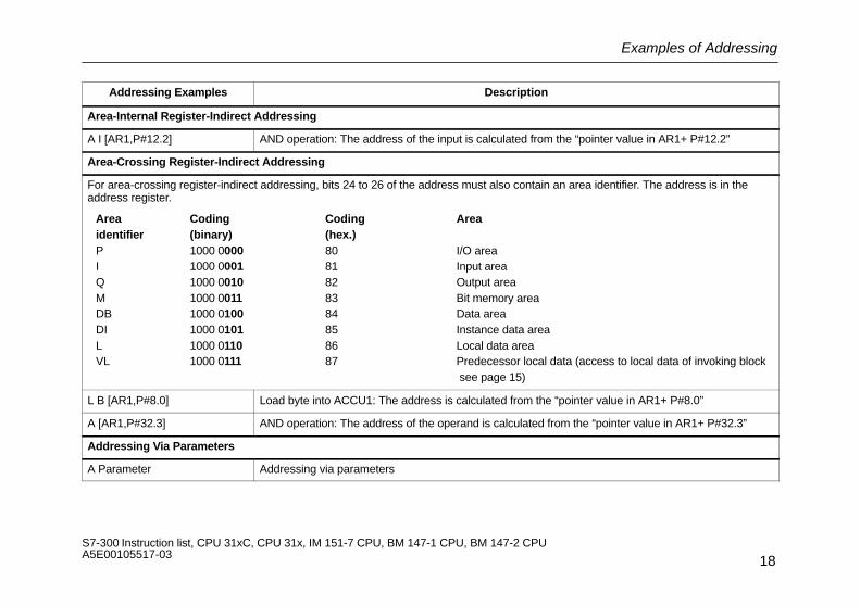
Area-Internal Register-Indirect Addressing
A I [AR1,P#12.2] AND operation: The address of the input is calculated from the “pointer value in AR1+ P#12.2”
Area-Crossing Register-Indirect Addressing
For area-crossing register-indirect addressing, bits 24 to 26 of the address must also contain an area identifier. The address is in theaddress register.
Area Coding Coding Areaidentifier (binary) (hex.)P 1000 0000 80 I/O areaI 1000 0001 81 Input areaQ 1000 0010 82 Output areaM 1000 0011 83 Bit memory areaDB 1000 0100 84 Data areaDI 1000 0101 85 Instance data areaL 1000 0110 86 Local data areaVL 1000 0111 87 Predecessor local data (access to local data of invoking block
see page 15)
L B [AR1,P#8.0] Load byte into ACCU1: The address is calculated from the “pointer value in AR1+ P#8.0”
A [AR1,P#32.3] AND operation: The address of the operand is calculated from the “pointer value in AR1+ P#32.3”
Addressing Via Parameters
A Parameter Addressing via parameters
Examples of how to calculate the pointer
19S7-300 Instruction list, CPU 31xC, CPU 31x, IM 151-7 CPU, BM 147-1 CPU, BM 147-2 CPU A5E00105517-03
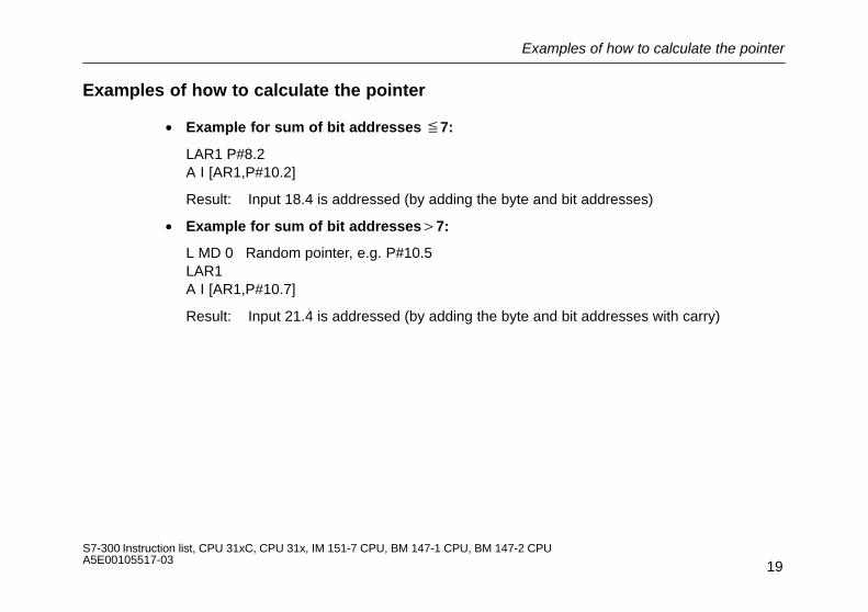
Examples of how to calculate the pointer
• Example for sum of bit addresses �7:
LAR1 P#8.2A I [AR1,P#10.2]
Result: Input 18.4 is addressed (by adding the byte and bit addresses)
• Example for sum of bit addresses�7:
L MD 0 Random pointer, e.g. P#10.5LAR1A I [AR1,P#10.7]
Result: Input 21.4 is addressed (by adding the byte and bit addresses with carry)
Execution Times with Indirect Addressing
20S7-300 Instruction list, CPU 31xC, CPU 31x, IM 151-7 CPU, BM 147-1 CPU, BM 147-2 CPU A5E00105517-03
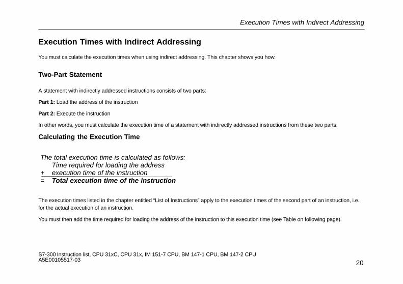
Execution Times with Indirect Addressing
You must calculate the execution times when using indirect addressing. This chapter shows you how.
Two-Part Statement
A statement with indirectly addressed instructions consists of two parts:
Part 1: Load the address of the instruction
Part 2: Execute the instruction
In other words, you must calculate the execution time of a statement with indirectly addressed instructions from these two parts.
Calculating the Execution Time
The total execution time is calculated as follows:Time required for loading the address
+ execution time of the instruction= Total execution time of the instruction
The execution times listed in the chapter entitled “List of Instructions” apply to the execution times of the second part of an instruction, i.e.for the actual execution of an instruction.
You must then add the time required for loading the address of the instruction to this execution time (see Table on following page).
Execution Times with Indirect Addressing
21S7-300 Instruction list, CPU 31xC, CPU 31x, IM 151-7 CPU, BM 147-1 CPU, BM 147-2 CPU A5E00105517-03
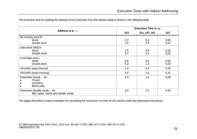
The execution time for loading the address of the instruction from the various areas is shown in the following table.
Address is in Execution Time in �s
Address is in ...312 31x, 147, 151 317
Bit memory area MWordDouble word
0.71.6
0.40.9
0,080,21
Data block DB/DXWordDouble word
1.53.7
0.82.0
0,200,25
Local data area LWordDouble word
0.92.2
0.51.2
0,080,20
AR1/AR2 (area-internal) 1.0 0.5 0,20
AR1/AR2 (area-crossing) 3.0 1.6 0,31
Parameter (word) ... for:• Timers• Counters• Block calls
2.0 1.0 0,08
Parameter (double word) ... forBits, bytes, words and double words
4.0 2.0 0,26
The pages that follow contain examples for calculating the instruction run time for the various indirectly addressed instructions.

Calculating the Execution Time Using a CPU 314C-2 DP as an Example
22S7-300 Instruction list, CPU 31xC, CPU 31x, IM 151-7 CPU, BM 147-1 CPU, BM 147-2 CPU A5E00105517-03
Calculating the Execution Time Using a CPU 314C-2 DP as an Example
You will find a few examples here for calculating the execution times for the various methods of indirect addressing. Execution times arecalculated for the CPU 314C-2 DP.
Calculating the Execution Times for Area-Internal Memory-Indirect Addressing
Example: A I [DBD 12]
Step 1: Load the contents of DBD 12 (time required is listed in the table on page 21)
Address is in ... Execution Time in �s
Bit memory area MWordDouble word
0.40.9
Data block DB/DIWordDouble word 2.0
0.8

Calculating the Execution Time Using a CPU 314C-2 DP as an Example
23S7-300 Instruction list, CPU 31xC, CPU 31x, IM 151-7 CPU, BM 147-1 CPU, BM 147-2 CPU A5E00105517-03
Step 2: AND the input addressed in this way (you will find the execution time in the tables in the chapter entitled “List of Instructions”)
Typical Execution Time in �s
Direct Addressing Indirect Addressing
0.1
:
1.6+
:Time for A I
Total execution time: 2.0 µs+ 1.6 µs= 3.6 µs
Calculating the Execution Time Using a CPU 314C-2 DP as an Example
24S7-300 Instruction list, CPU 31xC, CPU 31x, IM 151-7 CPU, BM 147-1 CPU, BM 147-2 CPU A5E00105517-03
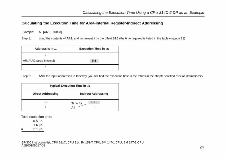
Calculating the Execution Time for Area-Internal Register-Indirect Addressing
Example: A I [AR1, P#34.3]
Step 1: Load the contents of AR1, and increment it by the offset 34.3 (the time required is listed in the table on page 21)
Address is in ... Execution Time in �s
: :
AR1/AR2 (area-internal) 0.5
: :
Step 2: AND the input addressed in this way (you will find the execution time in the tables in the chapter entitled “List of Instructions”)
Typical Execution Time in �s
Direct Addressing Indirect Addressing
0.1
:
1.6+
:Time for A I
Total execution time: 0.5 µs+ 1.6 µs= 2.1 µs

Calculating the Execution Time Using a CPU 314C-2 DP as an Example
25S7-300 Instruction list, CPU 31xC, CPU 31x, IM 151-7 CPU, BM 147-1 CPU, BM 147-2 CPU A5E00105517-03
Calculating the Execution Time for Area-Crossing Memory-Indirect Addressing
Example: A [AR1, P#23.1] ... with I 1.0 in AR1
Step 1: Load the contents of AR1, and increment them by the offset 23.1 (the time required is in the table on page 21)
Address is in ... Execution Time in �s
: :
AR1/AR2 (area-crossing) 1.6
: :
Step 2: AND the input addressed in this way (you will find the execution time in the tables in the chapter entitled “List of Instructions”)
Typical Execution Time in �s
Direct Addressing Indirect Addressing
0.1
:
1.6+
:Time for A I
Total execution time: 1.6 µs+ 1.6 µs= 3.2 µs
Calculating the Execution Time Using a CPU 314C-2 DP as an Example
26S7-300 Instruction list, CPU 31xC, CPU 31x, IM 151-7 CPU, BM 147-1 CPU, BM 147-2 CPU A5E00105517-03
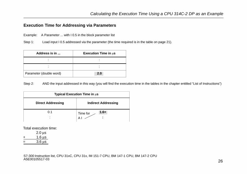
Execution Time for Addressing via Parameters
Example: A Parameter ... with I 0.5 in the block parameter list
Step 1: Load input I 0.5 addressed via the parameter (the time required is in the table on page 21).
Address is in ... Execution Time in �s
: :
: :
Parameter (double word) 2.0
Step 2: AND the input addressed in this way (you will find the execution time in the tables in the chapter entitled “List of Instructions”)
Typical Execution Time in �s
Direct Addressing Indirect Addressing
0.1
:
1.6+
:Time for A I
Total execution time: 2.0 µs+ 1.6 µs= 3.6 µs

List of Instructions
27S7-300 Instruction list, CPU 31xC, CPU 31x, IM 151-7 CPU, BM 147-1 CPU, BM 147-2 CPU A5E00105517-03
List of Instructions
This chapter contains the complete list of S7-300 instructions. The descriptions have been kept as concise as possible. You will find a de-tailed functional description in the various STEP 7 reference manuals.Please note that, in the case of indirect addressing (examples see page 18), you must add the time required for loading the address of theparticular instruction to the execution times listed (see page 21).

Bit Logic Instructions
28S7-300 Instruction list, CPU 31xC, CPU 31x, IM 151-7 CPU, BM 147-1 CPU, BM 147-2 CPU A5E00105517-03
Bit Logic Instructions
Examining the signal state of the addressed instruction and gating the result with the RLO according to the appropriate logic function.
Typical Execution Time in �s
InstructionAddress
DescriptionLength
in
Direct Addressing
Indirect Addressing 1)
Instruction Identifier Description inWords2)
31231x,147,151
317 31231x,147,151
317
AI/Q a.bM a.bL a.bDBX a.bDIX a.b
ANDInput/outputBit memoryLocal data bitData bitInstance data bit
1/21/2222
0.20.40.72.92.9
0.10.20.31.41.4
0,050,050,060,170,17
3.0+3.2+3.7+4.5+4.5+
1.6+1.7+2.0+2.4+2.4+
0,09+0,09+0,07+0,08+0,07+
c[AR1,m]c[AR2,m][AR1,m][AR2,m]Parameter
Register-ind., area-internal (AR1)Register-ind., area-internal (AR2)Area-crossing via (AR1)Area-crossing via (AR2)Via parameter
22222
–––––
–––––
–––––
+++++
+++++
+++++
Status word for: A BR CC 1 CC 0 OV OS OR STA RLO FCInstruction depends on: – – – – – Yes – Yes Yes
Instruction affects: – – – – – Yes Yes Yes 1
1) Plus time required for loading the address of the instruction (see page 21)2) With direct instruction addressing/ with indirect instruction adressing
Bit Logic Instructions
29S7-300 Instruction list, CPU 31xC, CPU 31x, IM 151-7 CPU, BM 147-1 CPU, BM 147-2 CPU A5E00105517-03
Typical Execution Time in �s
InstructionAddress
DescriptionLength
in
DirectAddressing
IndirectAddressing 1)
InstructionAddressIdentifier
Description inWords2)
31231x,147,151
317 31231x,147,151
317
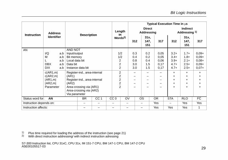
ANI/Q a.bM a.bL a.bDBX a.bDIX a.b
AND NOTInput/outputBit memoryLocal data bitData bitInstance data bit
1/21/2222
0.30.40.83.03.0
0.20.20.41.51.5
0,050,050,060,170,17
3.2+3.4+3.9+4.7+4.7+
1.7+1.8+2.1+2.5+2.5+
0,09+0,09+0,08+0,09+0,07+
c[AR1,m]c[AR2,m][AR1,m][AR2,m]Parameter
Register-ind., area-internal(AR1)Register-ind., area-internal(AR2)Area-crossing via (AR1)Area-crossing via (AR2)Via parameter
22222
–––––
–––––
–––––
+++++
+++++
+++++
Status word for: AN BR CC 1 CC 0 OV OS OR STA RLO FC
Instruction depends on: – – – – – Yes – Yes Yes
Instruction affects: – – – – – Yes Yes Yes 1
1) Plus time required for loading the address of the instruction (see page 21)2) With direct instruction addressing/ with indirect instruction adressing

Bit Logic Instructions
30S7-300 Instruction list, CPU 31xC, CPU 31x, IM 151-7 CPU, BM 147-1 CPU, BM 147-2 CPU A5E00105517-03
Typical Execution Time in �s
In-struc-
AddressDescription
Lengthin
DirectAddressing
IndirectAddressing 1)
struc-tion
AddressIdentifier
Description inWords 2)
31231x,147,151
317 31231x,147,151
317
OI/Q a.bM a.bL a.bDBX a.bDIX a.b
ORInput/outputBit memoryLocal data bitData bitInstance data bit
1/21/2222
0.20.30.72.92.9
0.10.20.31.41.4
0,050,050,060,200,20
3.0+3.2+3.7+4.6+4.6+
1,6+1,7+2.0+2.4+2.4+
0,11+0,11+0,10+0,11+0,09+
c[AR1,m]c[AR2,m][AR1,m][AR2,m]Parameter
Register-ind., area-internal (AR1)Register-ind., area-internal (AR2)Area-crossing via (AR1)Area-crossing via (AR2)Via parameter
22222
–––––
–––––
–––––
+++++
+++++
+++++
Status word for: O BR CC 1 CC 0 OV OS OR STA RLO2 FC
Instruction depends on: – – – – – – – Yes Yes
Instruction affects: – – – – – 0 Yes Yes 1
1) Plus time required for loading the address of the instruction (see page 21)2) With direct instruction addressing/ with indirect instruction adressing
Bit Logic Instructions
31S7-300 Instruction list, CPU 31xC, CPU 31x, IM 151-7 CPU, BM 147-1 CPU, BM 147-2 CPU A5E00105517-03
Typical Execution Time in �s
InstructionAddress
DescriptionLength
in
DirectAddressing
IndirectAddressing 1)
InstructionAddressIdentifier
Description inWords 2)
31231x,147,151
317 31231x,147,151
317
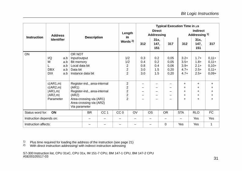
ONI/Q a.bM a.bL a.bDBX a.bDIX a.b
OR NOTInput/outputBit memoryLocal data bitData bitInstance data bit
1/21/2222
0.30.40.83.03.0
0.20.20.41.51.5
0,050,050,060,200,20
3.2+3.5+3.9+4.7+4.7+
1.7+1.8+2.1+2.5+2.5+
0,11+0,11+0,10+0,11+0,09+
c[AR1,m]c[AR2,m][AR1,m][AR2,m]Parameter
Register-ind., area-internal(AR1)Register-ind., area-internal(AR2)Area-crossing via (AR1)Area-crossing via (AR2)Via parameter
22222
–––––
–––––
–––––
+++++
+++++
+++++
Status word for: ON BR CC 1 CC 0 OV OS OR STA RLO FC
Instruction depends on: – – – – – – – Yes Yes
Instruction affects: – – – – – 0 Yes Yes 1
1) Plus time required for loading the address of the instruction (see page 21)2) With direct instruction addressing/ with indirect instruction adressing

Bit Logic Instructions
32S7-300 Instruction list, CPU 31xC, CPU 31x, IM 151-7 CPU, BM 147-1 CPU, BM 147-2 CPU A5E00105517-03
Typical Execution Time in �s
InstructionAddressIdentifier
DescriptionLength
in
DirectAddressing
IndirectAddressing 1)
InstructionIdentifier
Description inWords 2)
31231x,147,151
317 31231x,147,151
317
XI/Q a.bM a.bL a.bDBX a.bDIX a.b
EXCLUSIVE ORInput/outputBit memoryLocal data bitData bitInstance data bit
1/21/2222
0.20.30.72.92.9
0.10.20.31.41.4
0,050,050,060,200,20
2.9+3.2+3.7+4.5+4.5+
1.6+1.7+2.0+2.4+2.4+
0,11+0,11+0,10+0,11+0,09+
c[AR1,m]c[AR2,m][AR1,m][AR2,m]Parameter
Register-ind., area-internal(AR1)Register-ind., area-internal(AR2)Area-crossing via (AR1)Area-crossing via (AR2)Via parameter
22222
–––––
–––––
–––––
+++++
+++++
+++++
Status word for: X BR CC 1 CC 0 OV OS OR STA RLO FC
Instruction depends on: – – – – – – – Yes Yes
Instruction affects: – – – – – 0 Yes Yes 1
1) Plus time required for loading the address of the instruction (see page 21)2) With direct instruction addressing/ with indirect instruction adressing

Bit Logic Instructions
33S7-300 Instruction list, CPU 31xC, CPU 31x, IM 151-7 CPU, BM 147-1 CPU, BM 147-2 CPU A5E00105517-03
Typical Execution Time in �s
InstructionAddress
DescriptionLength
in
DirectAddressing
IndirectAddressing 1)
InstructionAddressIdentifier
Description inWords 2)
31231x,147,151
317 31231x,147,151
317
XNI/Q a.bM a.bL a.bDBX a.bDIX a.b
EXCLUSIVE OR NOTInput/outputBit memoryLocal data bitData bitInstance data bit
1/21/2222
0.30.40.83.03.0
0.20.20.41.51.5
0,050,050,060,200,20
3.2+3.5+3.9+4.7+4.7+
1.7+1.8+2.1+2.5+2.5+
0,11+0,11+0,10+0,11+0,10+
c[AR1,m]c[AR2,m][AR1,m][AR2,m]Parameter
Register-ind., area-internal(AR1)Register-ind., area-internal(AR2)Area-crossing via (AR1)Area-crossing via (AR2)Via parameter
22222
–––––
–––––
–––––
+++++
+++++
+++++
Status word for: XN BR CC 1 CC 0 OV OS OR STA RLO FC
Instruction depends on: – – – – – – – Yes Yes
Instruction affects: – – – – – 0 Yes Yes 1
1) Plus time required for loading the address of the instruction (see page 21)2) With direct instruction addressing/ with indirect instruction adressing

Bit Logic Instructions with Parenthetical Expressions
34S7-300 Instruction list, CPU 31xC, CPU 31x, IM 151-7 CPU, BM 147-1 CPU, BM 147-2 CPU A5E00105517-03
Bit Logic Instructions with Parenthetical Expressions
Saving the BR, RLO and OR bits and a function identifier (A, AN, ...) to the nesting stack. Seven nesting levels are possible per block.
AddressTypical Execution Time in �s
InstructionAddressIdentifier Description Length in
Words312
31x, 147,151
317
A( AND left parenthesis 1 3.2 1.6 0,18
AN( AND NOT left parenthesis 1 3.3 1.6 0,18
O( OR left parenthesis 1 3.0 1.5 0,11
ON( OR NOT left parenthesis 1 3.0 1.5 0,11
X( EXCLUSIVE OR left parenthesis 1 3.0 1.5 0,11
XN( EXCLUSIVE OR NOT left parenthesis 1 3.0 1.5 0,11
Status word for: A(, AN(, O(, ON(, X(, XN( BR CC 1 CC 0 OV OS OR STA RLO FC
Instruction depends on: Yes – – – – Yes – Yes Yes
Instruction affects: – – – – – 0 1 – 0

Bit Logic Instructions with Parenthetical Expressions
35S7-300 Instruction list, CPU 31xC, CPU 31x, IM 151-7 CPU, BM 147-1 CPU, BM 147-2 CPU A5E00105517-03
InstructionAddress
Description Length in Typical Execution Time in �sInstruction
AddressIdentifier
Description Length inWords 312 31x, 147, 151 317
) Right parenthesis, popping an entry offthe nesting stack, gating the RLO withthe current RLO in the processor
1 1.0 1.0 0,1
Status word for: ) BR CC 1 CC 0 OV OS OR STA RLO FC
Instruction depends on: – – – – – – – Yes –
Instruction affects: Yes – – – – Yes 1 Yes 1

ORing of AND Operations
36S7-300 Instruction list, CPU 31xC, CPU 31x, IM 151-7 CPU, BM 147-1 CPU, BM 147-2 CPU A5E00105517-03
ORing of AND Operations
The ORing of AND operations is implemented according to the rule: AND before OR.
InstructionAddress
Description Length in Typical Execution Time in �s Instruction
AddressIdentifier
Description Length in Words 312 31x, 147, 151 317
O ORing of AND operations according tothe rule: AND before OR
1 0.2 0.1 0,04
Status word for: O BR CC 1 CC 0 OV OS OR STA RLO FC
Instruction depends on: – – – – – Yes – Yes Yes
Instruction affects: – – – – – Yes 1 – Yes

Logic Instructions with Timers and Counters
37S7-300 Instruction list, CPU 31xC, CPU 31x, IM 151-7 CPU, BM 147-1 CPU, BM 147-2 CPU A5E00105517-03
Logic Instructions with Timers and Counters
Examining the signal state of the addressed timer/counter and gating the result with the RLO according to the appropriate logic function.
Typical Execution Time in �s
InstructionAddress
DescriptionLength
in
DirectAddressing
IndirectAddressing 1)
InstructionAddressIdentifier
Description inWords 2)
31231x,147,151
317 31231x,147,151
317
ATC
ANDTimerCounter
1/2+1/2+
0.60.3
0.30.2
0,360,10
2.1+2.0+
1.1+1.1+
0,42+0,13+
Timer para.Counter p.
Timer/counter (addressed via parameter)
2 ––
––
––
++
++
++
Status word for: A CC 1 BR CC 0 OV OS OR STA RLO FC
Instruction depends on: – – – – – Yes – Yes Yes
Instruction affects: – – – – – Yes Yes Yes 1
1) Plus time required for loading the address of the instruction (see page 21)2) With direct instruction addressing/ with indirect instruction adressing

Logic Instructions with Timers and Counters
38S7-300 Instruction list, CPU 31xC, CPU 31x, IM 151-7 CPU, BM 147-1 CPU, BM 147-2 CPU A5E00105517-03
Typical Execution Time in �s
InstructionAddressIdentifier Description
Lengthin
DirectAddressing
IndirectAddressing 1)Instruction Identifier Description in
Words 2)
31231x,147,151
317 31231x,147,151
317
ANTC
AND NOTTimerCounter
1/21/2
0.80.5
0.40.3
0,360,10
2.3+2.2+
1.2+1.2+
0,42+0,13+
Timer para.Counter p.
Timer/counter (addressed via parameter)
2 ––
––
––
++
++
++
Status word for: AN BR CC 1 CC 0 OV OS OR STA RLO FC
Instruction depends on: – – – – – Yes – Yes Yes
Instruction affects: – – – – – Yes Yes Yes 1
1) Plus time required for loading the address of the instruction (see page 21)2) With direct instruction addressing/ with indirect instruction adressing

Logic Instructions with Timers and Counters
39S7-300 Instruction list, CPU 31xC, CPU 31x, IM 151-7 CPU, BM 147-1 CPU, BM 147-2 CPU A5E00105517-03
Typical Execution Time in �s
InstructionAddress
DescriptionLength
in
DirectAddressing
IndirectAddressing 1)
InstructionAddressIdentifier
Description inWords 2)
31231x,147,151
317 31231x,147,151
317
O TC
OR timerOR counter
1/21/2
0.60.3
0.30.2
0,360,10
2.1+2.0+
1.1+1.0+
0,42+0,13+
Timerpara.Counter p.
OR timer/counter (addressed via parameter)
2 ––
––
––
++
++
++
ON TC
OR NOT timerOR NOT counter
1/21/2
0.80.5
0.40.3
0,360,10
2.3+2.2+
1.2+1.1+
0,42+0,13+
Timerpara.Counter p.
OR NOT timer/counter (addressed via parameter)
2 ––
––
––
++
++
++
1) Plus time required for loading the address of the instruction (see page 21)2) With direct instruction addressing/ with indirect instruction adressing
Logic Instructions with Timers and Counters
40S7-300 Instruction list, CPU 31xC, CPU 31x, IM 151-7 CPU, BM 147-1 CPU, BM 147-2 CPU A5E00105517-03
Instruction
Typical Execution Time in �s
DescriptionInstruction
IndirectAddressing 1)
DirectAddressingLength
inWords 2)
DescriptionInstruction
31731x,147,151
31231731x,147,151
312
Lengthin
Words 2)Description
AddressIdentifier
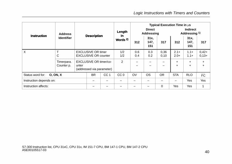
X TC
EXCLUSIVE OR timerEXCLUSIVE OR counter
1/21/2
0.60.4
0.30.2
0,360,10
2.1+2.0+
1.1+1.1+
0,42+0,13+
Timerpara.Counter p.
EXCLUSIVE OR timer/co-unter (addressed via parameter)
2 ––
––
––
++
++
++
Status word for: O, ON, X BR CC 1 CC 0 OV OS OR STA RLO FC
Instruction depends on: – – – – – – – Yes Yes
Instruction affects: – – – – – 0 Yes Yes 1
Logic Instructions with Timers and Counters
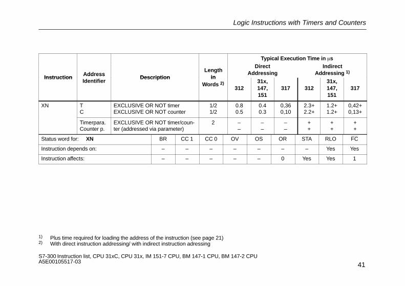
41S7-300 Instruction list, CPU 31xC, CPU 31x, IM 151-7 CPU, BM 147-1 CPU, BM 147-2 CPU A5E00105517-03
Typical Execution Time in �s
InstructionAddress
DescriptionLength
in
DirectAddressing
IndirectAddressing 1)
InstructionAddressIdentifier
Description inWords 2)
31231x,147,151
317 31231x,147,151
317
XN TC
EXCLUSIVE OR NOT timerEXCLUSIVE OR NOT counter
1/21/2
0.80.5
0.40.3
0,360,10
2.3+2.2+
1.2+1.2+
0,42+0,13+
Timerpara.Counter p.
EXCLUSIVE OR NOT timer/coun-ter (addressed via parameter)
2 ––
––
––
++
++
++
Status word for: XN BR CC 1 CC 0 OV OS OR STA RLO FC
Instruction depends on: – – – – – – – Yes Yes
Instruction affects: – – – – – 0 Yes Yes 1
1) Plus time required for loading the address of the instruction (see page 21)2) With direct instruction addressing/ with indirect instruction adressing

Word Logic Instructions with the Contents of Accumulator 1
42S7-300 Instruction list, CPU 31xC, CPU 31x, IM 151-7 CPU, BM 147-1 CPU, BM 147-2 CPU A5E00105517-03
Word Logic Instructions with the Contents of Accumulator 1
Gating the contents of ACCU1 and/or ACCU1-L with a word or double word according to the appropriate function. The word or double wordis either a constant in the instruction or in ACCU2. The result is in ACCU1 and/or ACCU1-L.
AddressTypical Execution Time in �s
InstructionAddressIdentifier Description Length in
Words312
31x, 147,151
317
AW AND ACCU2-L 1 0.6 0.3 0,21
AW k16 AND 16-bit constant 2 0.6 0.3 0,19
OW OR ACCU2-L 1 0.6 0.3 0,18
OW k16 OR 16-bit constant 2 0.6 0.3 0,18
XOW EXCLUSIVE OR ACCU2-L 1 0.6 0.3 0,21
XOW k16 EXCLUSIVE OR 16-bit constant 2 0.6 0.3 0,21
AD AND ACCU2 1 1.9 1.0 0,13
AD k32 AND 32-bit constant 3 2.1 1.0 0,18
Status word for: AW, OW, XOW, AD BR CC 1 CC 0 OV OS OR STA RLO FC
Instruction depends on: – – – – – – – – –
Instruction affects: – Yes 0 0 – – – – –

Word Logic Instructions with the Contents of Accumulator 1
43S7-300 Instruction list, CPU 31xC, CPU 31x, IM 151-7 CPU, BM 147-1 CPU, BM 147-2 CPU A5E00105517-03
AddressTypical Execution Time in �s
InstructionAddressIdentifier Description Length in
Words312
31x, 147,151
317
OD OR ACCU2 1 1.9 1.0 0,13
OD k32 OR 32-bit constant 3 2.1 1.0 0,18
XOD EXCLUSIVE OR ACCU2 1 1.9 1.0 0,13
XOD k32 EXCLUSIVE OR 32-bit constant 3 2.1 1.0 0,18
Status word for: OD, XOD BR CC 1 CC 0 OV OS OR STA RLO FC
Instruction depends on: – – – – – – – – –
Instruction affects: – Yes 0 0 – – – – –

Evaluating Conditions Using AND, OR and EXCLUSIVE OR
44S7-300 Instruction list, CPU 31xC, CPU 31x, IM 151-7 CPU, BM 147-1 CPU, BM 147-2 CPU A5E00105517-03
Evaluating Conditions Using AND, OR and EXCLUSIVE OR
Examining the specified conditions for their signal status, and gating the result with the RLO according to the appropriate function.
AddressTypical Execution Time in �s
InstructionAddressIdentifier Description Length
in Words312
31x, 147,151
317
A/O/ X
==0 AND, OR, EXCLUSIVE ORResult=0 (CC 1=0)and (CC 0=0)
1 0.3 0.2 0,03
X>0 Result>0 (CC 1=1) and (CC 0=0) 1 0.5 0.3 0,05
<0 Result<0 (CC 1=0)and (CC 0=1) 1 0.5 0.3 0,05
<>0 Result�0 ((CC1=0)and(CC 0=1)or (CC1=1)and(CC 0=0)) 1 0.3 0.2 0,05
<=0 R<=0((CC 1=0) and (CC 0=1) or (CC1=0) and (CC 0=0)) 1 0.3 0.2 0,03
>=0 R>=0((CC 1=1) and (CC 0=0) or (CC1=0) and (CC 0=0)) 1 0.3 0.2 0,03
UO unordered math instruction (CC 1=1) and (CC 0=1) 1 0.3 0.2 0,03
OS OS=1 1 0.2 0.1 0,03
BR BR=1 1 0.2 0.1 0,03
OV OV=1 1 0.2 0.1 0,03
Status word for: A/ O/ X BR CC 1 CC 0 OV OS OR STA RLO FC
Instruction depends on: Yes Yes Yes Yes Yes Yes – Yes Yes
Instruction affects: – – – – – Yes Yes Yes 1

Evaluating Conditions Using AND, OR and EXCLUSIVE OR
45S7-300 Instruction list, CPU 31xC, CPU 31x, IM 151-7 CPU, BM 147-1 CPU, BM 147-2 CPU A5E00105517-03
AddressTypical Execution Time in �s
InstructionAddressIdentifier Description Length
in Words312
31x, 147,151
317
AN/ ON/XN
==0 AND NOT, OR NOT, EXCLUSIVE OR NOTResult=0 (CC 1=0) and (CC 0=0)
1 0.3 0.2 0,03
XN>0 Result>0 (CC 1=1) and (CC 0=0) 1 0.5 0.3 0,05
<0 Result<0 (CC 1=0) and (CC 0=1) 1 0.5 0.3 0,05
<>0 Result�0((CC 1=0) and (CC 0=1) or (CC 1=1) and (CC 0=0))
1 0.5 0.3 0,05
<=0 Result<=0((CC 1=0) and (CC 0=1) or (CC 1=0) and (CC 0=0))
1 0.2 0.1 0,03
>=0 Result>=0((CC 1=1) and (CC 0=0) or (CC 1=0) and (CC 0=0))
1 0.2 0.1 0,03
UO unordered math instruction (CC 1=1) and (CC 0=1) 1 0.5 0.3 0,03
OS OS=1 1 0.3 0.2 0,03
BR BR=1 1 0.3 0.2 0,03
OV OV=1 1 0.3 0.2 0,03
Status word for: AN/ ON/ XN BR CC 1 CC 0 OV OS OR STA RLO FC
Instruction depends on: Yes Yes Yes Yes Yes Yes – Yes Yes
Instruction affects: – – – – – Yes Yes Yes 1

Edge-Triggered Instructions
46S7-300 Instruction list, CPU 31xC, CPU 31x, IM 151-7 CPU, BM 147-1 CPU, BM 147-2 CPU A5E00105517-03
Edge-Triggered Instructions
Detection of an edge change. The current signal state of the RLO is compared with the signal state of the instruction or “edge bit memory”.FP detects a change in the RLO from “0” to “1”; FN detects a change in the RLO from “1” to “0”.
Typical Execution Time in �s
InstructionAddress
DescriptionLength
DirectAddressing
IndirectAddressing 1)
InstructionAddressIdentifier
DescriptionLength
in Words312
31x,147,151
317 31231x,147,151
317
FP I/Q a.bM a.bL a.bDBX a.bDIX a.b
Detecting the positive edge in theRLO. The bit addressed in the in-struction is the auxiliary edge bit memory.
22222
0.51.01.23.63.6
0.30.50.61.81.8
0,130,290,300,200,20
3.3+3.6+4.0+5.2+5.2+
1.8+1.9+2.1+2.7+2.7+
0,10+0,10+0,08+0,11+0,09+
c[AR1,m]c[AR2,m][AR1,m][AR2,m]Parameter
22222
–––––
–––––
–––––
+++++
+++++
+++++
Status word for: FP BR CC 1 CC 0 OV OS OR STA RLO FC
Instruction depends on: – – – – – – – Yes –
Instruction affects: – – – – – 0 Yes Yes 1
1) Plus time required for loading the address of the instruction (see page 21)

Edge-Triggered Instructions
47S7-300 Instruction list, CPU 31xC, CPU 31x, IM 151-7 CPU, BM 147-1 CPU, BM 147-2 CPU A5E00105517-03
Typical Execution Time in �s
InstructionAddress
DescriptionLength
DirectAddressing
IndirectAddressing 1)
InstructionAddressIdentifier
DescriptionLength
in Words312
31x,147,151
317 31231x,147,151
317
FN I/Q a.bM a.bL a.bDBX a.bDIX a.b
Detecting the negtive edge in theRLO. The bit addressed in the in-truction is the auxiliary edge bitmemory.
22222
0.71.11.33.73.7
0.30.50.71.91.9
0,13+0,13+0,14+0,20+0,20+
3.5+3.8+4.2+5.2+5.2+
1.9+2.0+2.2+2.8+2.8+
0,10+0,10+0,08+0,11+0,09+
c[AR1,m]c[AR2,m][AR1,m][AR2,m]Parameter
22222
–––––
–––––
–––––
+++++
+++++
+++++
Status word for: FN BR CC 1 CC 0 OV OS OR STA RLO FC
Instruction depends on: – – – – – – – Yes –
Instruction affects: – – – – – 0 Yes Yes 1
1) Plus time required for loading the address of the instruction (see page 21)
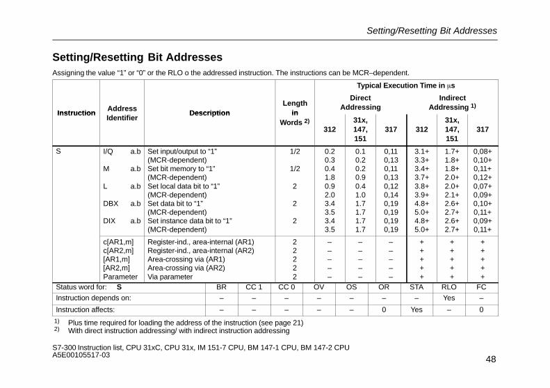
Setting/Resetting Bit Addresses
48S7-300 Instruction list, CPU 31xC, CPU 31x, IM 151-7 CPU, BM 147-1 CPU, BM 147-2 CPU A5E00105517-03
Setting/Resetting Bit AddressesAssigning the value “1” or “0” or the RLO o the addressed instruction. The instructions can be MCR–dependent.
Typical Execution Time in �s
InstructionAddress
DescriptionLength
in
DirectAddressing
IndirectAddressing 1)
InstructionIdentifier
Description inWords 2)
31231x,147,151
317 31231x,147,151
317
S I/Q a.b
M a.b
L a.b
DBX a.b
DIX a.b
Set input/output to “1”(MCR-dependent)Set bit memory to “1”(MCR-dependent)Set local data bit to “1”(MCR-dependent)Set data bit to “1”(MCR-dependent)Set instance data bit to “1”(MCR-dependent)
1/2
1/2
2
2
2
0.20.30.41.80.92.03.43.53.43.5
0.10.20.20.90.41.01.71.71.71.7
0,110,130,110,130,120,140,190,190,190,19
3.1+3.3+3.4+3.7+3.8+3.9+4.8+5.0+4.8+5.0+
1.7+1.8+1.8+2.0+2.0+2.1+2.6+2.7+2.6+2.7+
0,08+0,10+0,11+0,12+0,07+0,09+0,10+0,11+0,09+0,11+
c[AR1,m]c[AR2,m][AR1,m][AR2,m]Parameter
Register-ind., area-internal (AR1)Register-ind., area-internal (AR2)Area-crossing via (AR1)Area-crossing via (AR2)Via parameter
22222
–––––
–––––
–––––
+++++
+++++
+++++
Status word for: S BR CC 1 CC 0 OV OS OR STA RLO FC
Instruction depends on: – – – – – – – Yes –
Instruction affects: – – – – – 0 Yes – 0
1) Plus time required for loading the address of the instruction (see page 21) 2) With direct instruction addressing/ with indirect instruction addressing

Setting/Resetting Bit Addresses
49S7-300 Instruction list, CPU 31xC, CPU 31x, IM 151-7 CPU, BM 147-1 CPU, BM 147-2 CPU A5E00105517-03
Typical Execution Time in �s
InstructionAddress
DescriptionLength
in
DirectAddressing
IndirectAddressing 1)
InstructionAddressIdentifier
Description inWord 2)
31231x,147,151
317 31231x,147,151
317
R I/Q a.b
M a.b
L a.b
DBX a.b
DIX a.b
Reset input/output to “0”(MCR-dependent)Set bit memory to “0”(MCR-dependent)Set local data bit to“ 0”(MCR-dependent)Set data bit to “0”(MCR-dependent)Set instance data bit to “0”(MCR-dependent)
1/2
1/2
2
2
2
0.30.30.51.80.92.03.43.63.43.6
0.10.20.30.90.41.01.71.81.71.8
0,120,130,120,130,120,140,230,250,230,25
3.2+3.5+3.5+3.6+3.9+4.0+5.0+5.1+5.0+5.1+
1.7+1.8+1.8+1.9+2.1+2.1+2.6+2.7+2.6+2.7+
0,08+0,11+0,11+0,13+0,10+0,12+0,14+0,16+0,13+0,16+
c[AR1,m]c[AR2,m][AR1,m][AR2,m]Parameter
Register-ind., area-internal (AR1)Register-ind., area-internal (AR2)Area-crossing via (AR1)Area-crossing via (AR2)Via parameter
22222
–––––
–––––
–––––
+++++
+++++
+++++
Status word for: R BR CC 1 CC 0 OV OS OR STA RLO FCInstruction depends on: – – – – – – – Yes –Instruction affects: – – – – – 0 Yes – 0
1) Plus time required for loading the address of the instruction (see page 21) 2) With direct instruction addressing/ with indirect instruction addressing

Setting/Resetting Bit Addresses
50S7-300 Instruction list, CPU 31xC, CPU 31x, IM 151-7 CPU, BM 147-1 CPU, BM 147-2 CPU A5E00105517-03
Typical Execution Time in �s
InstructionAddress
DescriptionLength
in
DirectAddressing
IndirectAddressing 1)
InstructionAddressIdentifier
Description inWords 2)
31231x,147,151
317 31231x,147,151
317
= I/Q a.b
M a.b
L a.b
DBX a.b
DIX a.b
Assign RLO to input/output(MCR-dependent)Assign RLO to bit memory(MCR-dependent)Assign RLO to local data bit(MCR-dependent)Assign RLO to data bit(MCR-dependent)Assign RLO to instance data bit(MCR-dependent)
1/2
1/2
2
2
2
0.20.30.61.80.82.13.43.63.43.6
0.10.20.30.90.41.01.71.81.71.8
0,080,100,080,100,090,110,230,230,230,23
3.2+3.4+3.5+3.7+3.9+4.1+5.0+5.1+5.0+5.1+
1.7+1.8+1.8+2.0+2.0+2.2+2.6+2.7+2.6+2.7+
0,10+0,11+0,13+0,13+0,12+0,12+0,16+0,16+0,15+0,16+
c[AR1,m]c[AR2,m][AR1,m][AR2,m]Parameter
Register-ind., area-internal(AR1)Register-ind., area-internal(AR2)Area-crossing via (AR1)Area-crossing via (AR2)Via parameter
22222
–––––
–––––
–––––
+++++
+++++
+++++
Status word for: = BR CC 1 CC 0 OV OS OR STA RLO FC
Instruction depends on: – – – – – – – Yes –
Instruction affects: – – – – – 0 Yes – 0
1) Plus time required for loading the address of the instruction (see page 21) 2) With direct instruction addressing/ with indirect instruction addressing
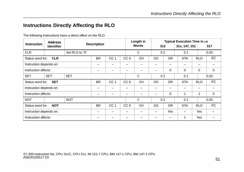
Instructions Directly Affecting the RLO
51S7-300 Instruction list, CPU 31xC, CPU 31x, IM 151-7 CPU, BM 147-1 CPU, BM 147-2 CPU A5E00105517-03
Instructions Directly Affecting the RLO
The following instructions have a direct effect on the RLO.
InstructionAddress
DescriptionLength in Typical Execution Time in �s
InstructionAddressIdentifier
Descriptiong
Words 312 31x, 147, 151 317
CLR Set RLO to ”0” 2 0.2 0.1 0,03
Status word for: CLR BR CC 1 CC 0 OV OS OR STA RLO FC
Instruction depends on: – – – – – – – – –
Instruction affects: – – – – – 0 0 0 0
SET SET SET 2 0.2 0.1 0,03
Status word for: SET BR CC 1 CC 0 OV OS OR STA RLO FC
Instruction depends on: – – – – – – – – –
Instruction affects: – – – – – 0 1 1 0
NOT NOT 2 0.2 0.1 0,03
Status word for: NOT BR CC 1 CC 0 OV OS OR STA RLO FC
Instruction depends on: – – – – – Yes – Yes –
Instruction affects: – – – – – – 1 Yes –

Instructions Directly Affecting the RLO
52S7-300 Instruction list, CPU 31xC, CPU 31x, IM 151-7 CPU, BM 147-1 CPU, BM 147-2 CPU A5E00105517-03
InstructionAddress
DescriptionLength in Typical Execution Time in �s
InstructionAddressIdentifier
Descriptiong
Words 312 31x, 147, 151 317
SAVE 1 0.2 0.1 0,03
Status word for: SAVE BR CC 1 CC 0 OV OS OR STA RLO FC
Instruction depends on: – – – – – – – Yes –
Instruction affects: Yes – – – – – – – –

Timer Instructions
53S7-300 Instruction list, CPU 31xC, CPU 31x, IM 151-7 CPU, BM 147-1 CPU, BM 147-2 CPU A5E00105517-03
Timer InstructionsStarting or resetting a timer (addressed directly or via a parameter). The time value must be in ACCU1-L.
Typical Execution Time in �s
InstructionAddress
DescriptionLength in
DirectAddressing
IndirectAddressing 1)
InstructionAddressIdentifier
DescriptionLength inWords2)
31231x,147,151
317 312 31x,147,151
317
SP T f Start timer as pulse on edge changefrom “0” to “1”
4/6 4.4 2.3 0,91 5.4+ 2.9+ 0,84+
Timer para.from “0” to “1”
2 – – – + + +
SE T f Start timer as exded pulse on edgechange from “0” to “1”
4/6 2.2 1.1 0,91 2.2+ 1.2+ 0,84+
Timer para.change from “0” to “1”
2 – – – + + +
SD T f Start timer as ON delay on edge changefrom “0” to “1”
4/6 4.6 2.4 0,91 5.5+ 3.0+ 0,85+
Timer para.from “0” to “1”
2 – – – + + +
SS T f Start timer as retive ON delay on edgechange from “0” to “1”
4/6 4.7 2.4 0,91 5.7+ 3.0+ 0,86+
Timer para.change from “0” to “1”
2 – – – + + +
Status word for: SP, SE, SD, SS, SF BR CC 1 CC 0 OV OS OR STA RLO FC
Instruction depends on: – – – – – – – Yes –
Instruction affects: – – – – – 0 – – 0
1) Plus time required for loading the address of the instruction (see page 21) 2) With direct instruction addressing/ with indirect instruction addressing

Timer Instructions
54S7-300 Instruction list, CPU 31xC, CPU 31x, IM 151-7 CPU, BM 147-1 CPU, BM 147-2 CPU A5E00105517-03
Typical Execution Time in �s
InstructionAddress
DescriptionLength in
DirectAddressing
IndirectAddressing 1)
InstructionAddressIdentifier
DescriptionLength inWords 2)
31231x,147,151
317 312 31x,147,151
317
SA T f Start timer as off-delay timer when theedge changes from “1” to “0”
4/6 4.9 2.5 0,97 5.9+ 3.2+ 0,88+
Timer para.edge changes from “1” to “0”.
2 – – – + + +
FR T f Enable timer for restarting on edgechange from “0” to “1” (reset edge bit
4/6 2.3 1.2 0,79 2.8+ 1.5+ 0,70
Timer para.change from “0” to “1” (reset edge bitmemory for starting timer) 2 – – – + + +
R T f Reset timer 4/6 2.3 1.1 0,44 2.8+ 1.5+ 0,41
Timer para. 2 – – – + + +
Status word for: FR, R BR CC 1 CC 0 OV OS OR STA RLO FC
Instruction depends on: – – – – – – – Yes –
Instruction affects: – – – – – 0 – – 0
1) Plus time required for loading the address of the instruction (see page 21) 2) With direct instruction addressing
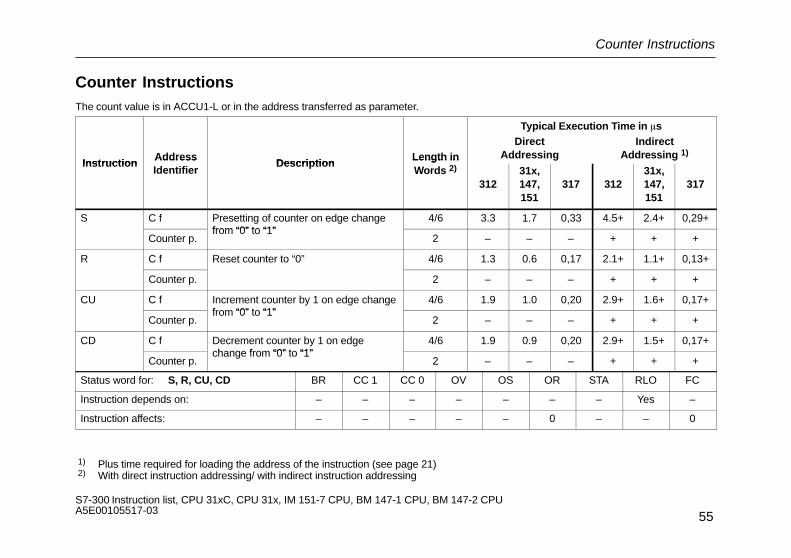
Counter Instructions
55S7-300 Instruction list, CPU 31xC, CPU 31x, IM 151-7 CPU, BM 147-1 CPU, BM 147-2 CPU A5E00105517-03
Counter InstructionsThe count value is in ACCU1-L or in the address transferred as parameter.
Typical Execution Time in �s
InstructionAddress
DescriptionLength in
DirectAddressing
IndirectAddressing 1)
InstructionAddressIdentifier
DescriptionLength inWords 2)
31231x,147,151
317 31231x,147,151
317
S C f Presetting of counter on edge changefrom “0” to “1”
4/6 3.3 1.7 0,33 4.5+ 2.4+ 0,29+
Counter p.from “0” to “1”
2 – – – + + +
R C f Reset counter to “0” 4/6 1.3 0.6 0,17 2.1+ 1.1+ 0,13+
Counter p. 2 – – – + + +
CU C f Increment counter by 1 on edge changefrom “0” to “1”
4/6 1.9 1.0 0,20 2.9+ 1.6+ 0,17+
Counter p.from “0” to “1”
2 – – – + + +
CD C f Decrement counter by 1 on edgechange from “0” to “1”
4/6 1.9 0.9 0,20 2.9+ 1.5+ 0,17+
Counter p.change from “0” to “1”
2 – – – + + +
Status word for: S, R, CU, CD BR CC 1 CC 0 OV OS OR STA RLO FC
Instruction depends on: – – – – – – – Yes –
Instruction affects: – – – – – 0 – – 0
1) Plus time required for loading the address of the instruction (see page 21) 2) With direct instruction addressing/ with indirect instruction addressing

Counter Instructions
56S7-300 Instruction list, CPU 31xC, CPU 31x, IM 151-7 CPU, BM 147-1 CPU, BM 147-2 CPU A5E00105517-03
Typical Execution Time in �s
InstructionAddress
DescriptionLength in
DirectAddressing
IndirectAddressing 1)
InstructionAddressIdentifier
DescriptionLength inWords 2)
31231x,147,151
317 31231x,147,151
317
FR C f Enable counter on edge change from “0”to “1” (reset edge bit memory for up and
2 1.6 0.8 0,20 2.6+ 1.4 0,17+
Counter p.to “1” (reset edge bit memory for up anddown counting) 2 – – – + + +
Status word for: FR BR CC 1 CC 0 OV OS OR STA RLO FC
Instruction depends on: – – – – – – – Yes –
Instruction affects: – – – – – 0 – – 0
1) Plus time required for loading the address of the instruction (see page 21) 2) With direct instruction addressing/ with indirect instruction addressing
Load Instructions
57S7-300 Instruction list, CPU 31xC, CPU 31x, IM 151-7 CPU, BM 147-1 CPU, BM 147-2 CPU A5E00105517-03
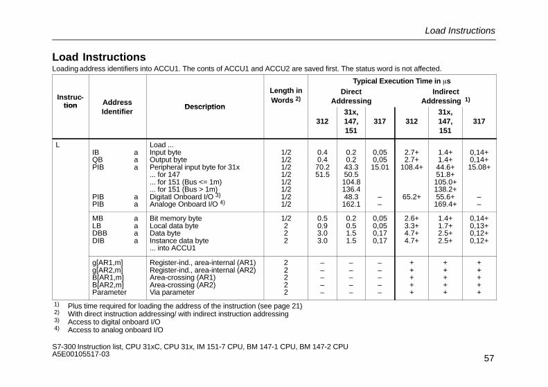
Load InstructionsLoading address identifiers into ACCU1. The conts of ACCU1 and ACCU2 are saved first. The status word is not affected.
Typical Execution Time in �s
Instruc-tion Address
Description
Length inWords 2)
DirectAddressing
IndirectAddressing 1)
tion AddressIdentifier
Description
31231x,147,151
317 31231x,147,151
317
LIB aQB aPIB a
PIB aPIB a
Load ...Input byteOutput bytePeripheral input byte for 31x... for 147... for 151 (Bus <= 1m)... for 151 (Bus > 1m)Digitatl Onboard I/O 3)
Analoge Onboard I/O 4)
1/21/21/21/21/21/21/21/2
0.40.470.251.5
0.20.243.350.5104.8136.448.3162.1
0,050,0515.01
––
2.7+2.7+
108.4+
65.2+
1.4+1.4+44.6+51.8+105.0+138.2+55.6+169.4+
0,14+0,14+15.08+
––
MB aLB aDBB aDIB a
Bit memory byteLocal data byteData byteInstance data byte... into ACCU1
1/2222
0.50.93.03.0
0.20.51.51.5
0,050,050,170,17
2.6+3.3+4.7+4.7+
1.4+1.7+2.5+2.5+
0,14+0,13+0,12+0,12+
g[AR1,m]g[AR2,m]B[AR1,m]B[AR2,m]Parameter
Register-ind., area-internal (AR1)Register-ind., area-internal (AR2)Area-crossing (AR1)Area-crossing (AR2)Via parameter
22222
–––––
–––––
–––––
+++++
+++++
+++++
1) Plus time required for loading the address of the instruction (see page 21) 2) With direct instruction addressing/ with indirect instruction addressing 3) Access to digital onboard I/O 4) Access to analog onboard I/O

Load Instructions
58S7-300 Instruction list, CPU 31xC, CPU 31x, IM 151-7 CPU, BM 147-1 CPU, BM 147-2 CPU A5E00105517-03
Typical Execution Time in �s
Instruc-tion Address
Description
Lengthin
W d 2)
DirectAddressing
IndirectAddressing 1)
tion AddressIdentifier
Description Words 2)
31231x,147,151
317 31231x,147,151
317
LIW aQW aPIW a
PIW aPIW a
Load ...Input wordOutput wordPeripheral input word for 31x... for 147... for 151 (Bus <= 1m)... for 151 (Bus > 1m)Digital Onboard I/O 3)
Analoge Onboard I/O 4)
1/21/2222222
0.60.676.7
–––
61.4–
0.30.347.456.2105.8141.757.6170.5
0,100,1020,71
–––––
2.9+2.9+
131.1+–––
77.6+–
1.6+1.6+48.9+57,8+108,4+142,5+
66.3179.2
0,15+0,15+20,75+
–––––
MW aLW aDBW aDIW a
Bit memory wordLocal data wordData wordInstance data word
into ACCU1
1/22
1/21/2
0.81.13.53.5
0.40.61.81.8
0,100,100,240,24
3.2+3.8+5.6+5.6+
1.7+2.0+3.0+3.0+
0,15+0,16+0,16+0,16+
... into ACCU1
h[AR1,m]h[AR2,m]W[AR1,m]W[AR2,m]Parameter
Register-ind., area-internal (AR1)Register-ind., area-internal (AR2)Area-crossing via (AR1)Area-crossing via (AR2)Via parameter
22222
–––––
–––––
–––––
+++++
+++++
+++++
1) Plus time required for loading the address of the instruction (see page 21) 2) With direct instruction addressing/ with indirect instruction addressing 3) Access to digital onboard I/O 4) Access to analog onboard I/O

Load Instructions
59S7-300 Instruction list, CPU 31xC, CPU 31x, IM 151-7 CPU, BM 147-1 CPU, BM 147-2 CPU A5E00105517-03
Typical Execution Time in �s
InstructionAddress
DescriptionLength
in
DirectAddressing
IndirectAddressing 1)
InstructionAddressIdentifier
Description inWords 2)
31231x,147,151
317 312x31x,147,151
317
LID aQD aPID a
PID a
Load ...Input double wordOutput double wordPeripheral input double word... for 147... for 151 (Bus <= 1m)... for 151 (Bus > 1m)Analoge Onboard I/O3)
1/21/222222
0.80.895.9
––––
0.40.460.268.71202161
303.0
0,200,2027,58
––––
3.1+3.1+
150.6+––––
1.6+1.6+61.9+70.8+21.8+163.6+323.0+
0,17+0,17+27,65+
––––
MD aLD aDBD aDID a
Bit memory double wordLocal data double wordData double wordInstance data double word... into ACCU1
1/2222
1.01.54.74.7
0.50.72.32.3
0,190,190,330,33
3.8+4.4+6.9+6.9+
2.0+2.3+3.7+3.7+
0,17+0,19+0,19+0,19+
i[AR1.m]i[AR2,m]D[AR1.m]D[AR2,m]Parameter
Register-ind., area-internal (AR1)Register-ind., area-internal (AR2)Area-crossing via (AR1)Area-crossing via (AR2)Via parameter
22222
–––––
–––––
–––––
+++++
+++++
+++++
1) Plus time required for loading the address of the instruction (see page 21) 2) With direct instruction addressing/ with indirect instruction addressing 3) Access to analog onboard I/O
Load Instructions
60S7-300 Instruction list, CPU 31xC, CPU 31x, IM 151-7 CPU, BM 147-1 CPU, BM 147-2 CPU A5E00105517-03
Typical Execution Time in �s
InstructionAddress
DescriptionLength in
DirectAddressing
IndirectAddressing 1)
InstructionAddressIdentifier
DescriptionLength in
Words312
31x,147,151
317 31231x,147,151
317
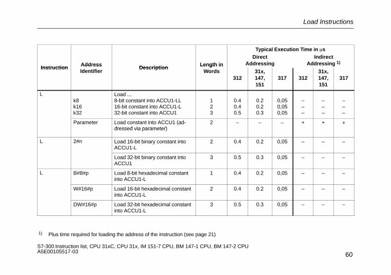
Lk8k16k32
Load ...8-bit constant into ACCU1-LL16-bit constant into ACCU1-L32-bit constant into ACCU1
123
0.40.40.5
0.20.20.3
0,050,050,05
–––
–––
–––
Parameter Load constant into ACCU1 (ad-dressed via parameter)
2 – – – + + +dressed via parameter)
L 2#n Load 16-bit binary constant intoACCU1-L
2 0.4 0.2 0,05 – – –
Load 32-bit binary constant intoACCU1
3 0.5 0.3 0,05 – – –
L B#8#p Load 8-bit hexadecimal constantinto ACCU1-L
1 0.4 0.2 0,05 – – –
W#16#p Load 16-bit hexadecimal constantinto ACCU1-L
2 0.4 0.2 0,05 – – –
DW#16#p Load 32-bit hexadecimal constantinto ACCU1-L
3 0.5 0.3 0,05 – – –
1) Plus time required for loading the address of the instruction (see page 21)

Load Instructions
61S7-300 Instruction list, CPU 31xC, CPU 31x, IM 151-7 CPU, BM 147-1 CPU, BM 147-2 CPU A5E00105517-03
Typical Execution Time in �sAdd
Typical Execution Time in �sInstruction Address
IdentifierDescription Length in
Words 31231x, 147,
151317
L ’x’ Load 1 characters 0.4 0.2 0,05
L ’xx’ Load 2 characters 2 0.4 0.2 0,05
L ’xxx’ Load 3 characters 0.5 0.3 0,08
L ’xxxx’ Load 4 characters 3 0.5 0.3 0,08
L D# date Load IEC date (BCD) 3 0.5 0.3 0,08
L S5T# time va-lue
Load S5 time constant (16 bits) 2 0.5 0.3 0,05
L TOD# time va-lue
Load 32-bit time constantIEC – daytime
3 0.5 0.3 0,08
L T# time value Load 16-bit timer constant 2 0.4 0.2 0,05
Load 32-bit timer constant 3 0.5 0.3 0,08
L C# count value Load 16-bit counter constant 2 0.4 0.2 0,05
L P# bit pointer Load bit pointer 3 0.5 0.3 0,08
L L# integer Load 32 bit integer constant 3 0.5 0.3 0,08
L Real number Load real number 3 0.5 0.3 0,08
Load Instructions for Timers and Counters
62S7-300 Instruction list, CPU 31xC, CPU 31x, IM 151-7 CPU, BM 147-1 CPU, BM 147-2 CPU A5E00105517-03
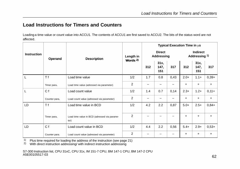
Load Instructions for Timers and Counters
Loading a time value or count value into ACCU1. The contents of ACCU1 are first saved to ACCU2. The bits of the status word are notaffected.
Typical Execution Time in �s
InstructionOperand Description
Length inWords 2)
DirectAddressing
IndirectAddressing 1)
Operand Description Words 2)
31231x,147,151
317 31231x,147,151
317
L T f Load time value 1/2 1.7 0.8 0,43 2.0+ 1.1+ 0,39+
Timer para. Load time value (adressed via parameter) 2 – – – + + +
L C f Load count value 1/2 1.4 0.7 0,14 2.3+ 1.2+ 0,11+
Counter para. Load count value (adressed via parameter) 2 – – – + + +
LD T f Load time value in BCD 1/2 4.2 2.2 0,87 5.0+ 2.5+ 0,84+
Timer para. Load time value in BCD (adressed via parame-
ter)
2 – – – + + +
LD C f Load count value in BCD 1/2 4.4 2.2 0,56 5.4+ 2.9+ 0,53+
Counter para. Load count value (adressed via parameter) 2 – – – + + +
1) Plus time required for loading the address of the instruction (see page 21) 2) With direct instruction addressing/ with indirect instruction addressing
Transfer Instructions
63S7-300 Instruction list, CPU 31xC, CPU 31x, IM 151-7 CPU, BM 147-1 CPU, BM 147-2 CPU A5E00105517-03
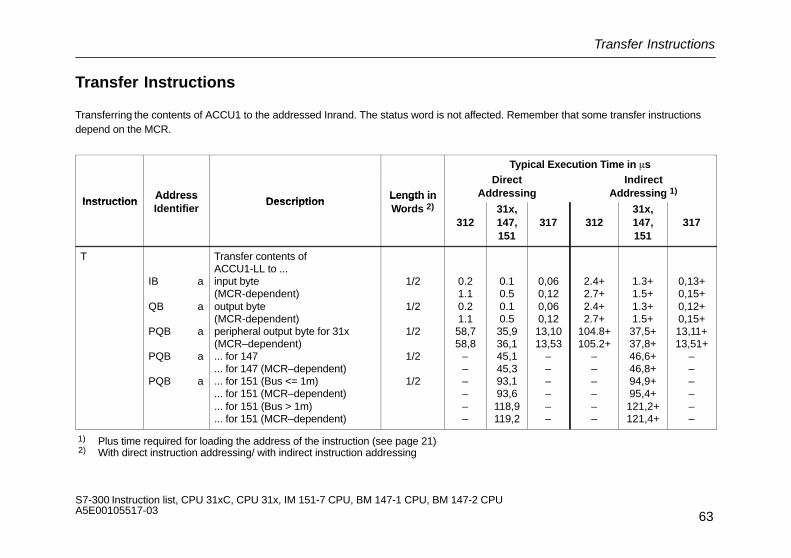
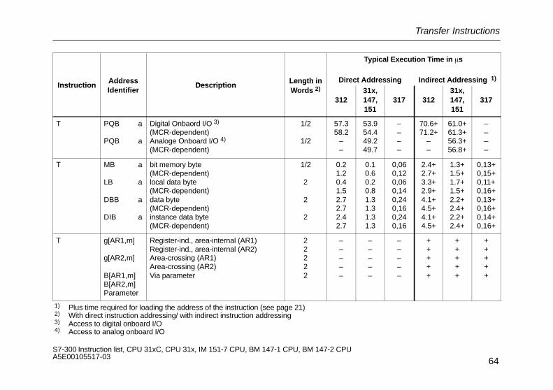
Transfer Instructions
Transferring the contents of ACCU1 to the addressed Inrand. The status word is not affected. Remember that some transfer instructionsdepend on the MCR.
Typical Execution Time in �s
InstructionAddress
DescriptionLength in
DirectAddressing
IndirectAddressing 1)
InstructionAddressIdentifier
DescriptionLength inWords 2)
31231x,147,151
317 31231x,147,151
317
T
IB a
QB a
PQB a
PQB a
PQB a
Transfer contents ofACCU1-LL to ...input byte(MCR-dependent)output byte(MCR-dependent)peripheral output byte for 31x(MCR–dependent)... for 147... for 147 (MCR–dependent)... for 151 (Bus <= 1m)... for 151 (MCR–dependent)... for 151 (Bus > 1m)... for 151 (MCR–dependent)
1/2
1/2
1/2
1/2
1/2
0.21.10.21.158,758,8
––––––
0.10.50.10.535,936,145,145,393,193,6118,9119,2
0,060,120,060,1213,1013,53
––––––
2.4+2.7+2.4+2.7+
104.8+105.2+
––––––
1.3+1.5+1.3+1.5+37,5+37,8+46,6+46,8+94,9+95,4+121,2+121,4+
0,13+0,15+0,12+0,15+13,11+13,51+
––––––
1) Plus time required for loading the address of the instruction (see page 21) 2) With direct instruction addressing/ with indirect instruction addressing
Transfer Instructions
64S7-300 Instruction list, CPU 31xC, CPU 31x, IM 151-7 CPU, BM 147-1 CPU, BM 147-2 CPU A5E00105517-03
Typical Execution Time in �s
InstructionAddress
DescriptionLength in Direct Addressing Indirect Addressing 1)
InstructionAddressIdentifier
DescriptionLength inWords 2)
31231x,147,151
317 31231x,147,151
317
T PQB a
PQB a
Digital Onbaord I/O 3)
(MCR-dependent)Analoge Onboard I/O 4)
(MCR-dependent)
1/2
1/2
57.358.2
––
53.954.449.249.7
––––
70.6+71.2+
––
61.0+61.3+56.3+56.8+
––––
T MB a
LB a
DBB a
DIB a
bit memory byte(MCR-dependent)local data byte(MCR-dependent)data byte(MCR-dependent)instance data byte(MCR-dependent)
1/2
2
2
2
0.21.20.41.52.72.72.42.7
0.10.60.20.81.31.31.31.3
0,060,120,060,140,240,160,240,16
2.4+2.7+3.3+2.9+4.1+4.5+4.1+4.5+
1.3+1.5+1.7+1.5+2.2+2.4+2.2+2.4+
0,13+0,15+0,11+0,16+0,13+0,16+0,14+0,16+
T g[AR1,m] g[AR2,m] B[AR1,m]B[AR2,m]Parameter
Register-ind., area-internal (AR1)Register-ind., area-internal (AR2)Area-crossing (AR1)Area-crossing (AR2)Via parameter
22222
–––––
–––––
–––––
+++++
+++++
+++++
1) Plus time required for loading the address of the instruction (see page 21) 2) With direct instruction addressing/ with indirect instruction addressing 3) Access to digital onboard I/O 4) Access to analog onboard I/O

Transfer Instructions
65S7-300 Instruction list, CPU 31xC, CPU 31x, IM 151-7 CPU, BM 147-1 CPU, BM 147-2 CPU A5E00105517-03
Typical Execution Time in �s
InstructionAddress
DescriptionLength in
DirectAddressing
IndirectAddressing 1)
InstructionAddressIdentifier
DescriptionLength inWords 2)
31231x,147,151
317 31231x,147,151
317
TIW
QW
PQW
PQW
PQW
PQW
PQW
Transfer contents of ACCU1-L to...input word(MCR-dependent)output word(MCR-dependent)peripheral output word(MCR-dependent)... for 147... for 147 (MCR–dependent)... for 151 (Bus <= 1m)... for 151 (MCR–dependent)... for 151 (Bus > 1m)... for 151 (MCR–dependent)
Digital Onbaord I/O 3)
(MCR-dependent)Analoge Onboard I/O 4)
(MCR-dependent)
1/2
1/2
1/2
1/2
1/2
1/2
1/2
1/2
0.41.10.41.164.464.6
––––––
70.571.1
––
0.20.60.20.640,440,652,853,198,999,0126,9126,4
66.166.466.166.4
0,130,130,130,1315,0415,32
––––––
––––
2.6+2.9+2.6+2.9+
121.6+120.5+
––––––
85.8+86.4+
––
1.4+1.5+1.4+1.5+41,8+42,1+53,9+54,1+100,3+100,6+128,1+128,4+
74.2+74.8+74.2+74.8+
0,14+0,16+0,14+0,16+14,99+15,43+
––––––
––––
1) Plus time required for loading the address of the instruction (see page 21) 2) With direct instruction addressing/ with indirect instruction addressing 3) Access to digital onboard I/O 4) Access to analog onboard I/O

Transfer Instructions
66S7-300 Instruction list, CPU 31xC, CPU 31x, IM 151-7 CPU, BM 147-1 CPU, BM 147-2 CPU A5E00105517-03
Typical Execution Time in �s
InstructionAddress
DescriptionLength in
DirectAddressing
IndirectAddressing 1)
InstructionAddressIdentifier
DescriptionLength inWords 2)
31231x,147,151
317 31231x,147,151
317
T MW
LW
DBW
DIW
bit memory word(MCR-dependent)local data word(MCR-dependent)data word(MCR-dependent)Instanz-data word(MCR-dependent)
1/2
2
2
2
0.41.50.51.63.23.23.23.2
0.20.70.20.81.61.61.51.6
0,180,150,120,150,300,160,300,15
3.2+3.5+3.8+3.3+4.8+5.2+4.8+5.2+
1.7+1.9+2.0+1.8+2.6+2.8+2.6+2.8+
0,16+0,18+0,15+0,22+0,17+0,19+0,17+0,19+
T h[AR1,m]h[AR2,m]W[AR1,m]W[AR2,m]Parameter
Register-ind., area-internal(AR1)Register-ind., area-internal(AR2)Area-crossing (AR1)Area-crossing (AR2)Via parameter
22222
–––––
–––––
–––––
+++++
+++++
+++++
1) Plus time required for loading the address of the instruction (see page 21) 2) With direct instruction addressing/ with indirect instruction addressing
Transfer Instructions
67S7-300 Instruction list, CPU 31xC, CPU 31x, IM 151-7 CPU, BM 147-1 CPU, BM 147-2 CPU A5E00105517-03
Instruction
Typical Execution Time in �s
Length inWords 2)
DescriptionAddressIdentifier
Instruction
IndirectAddressing 1)
DirectAddressingLength in
Words 2)DescriptionAddress
IdentifierInstruction
31731x,147,151
31231731x,147,151
312
Length inWords 2)Description
AddressIdentifier
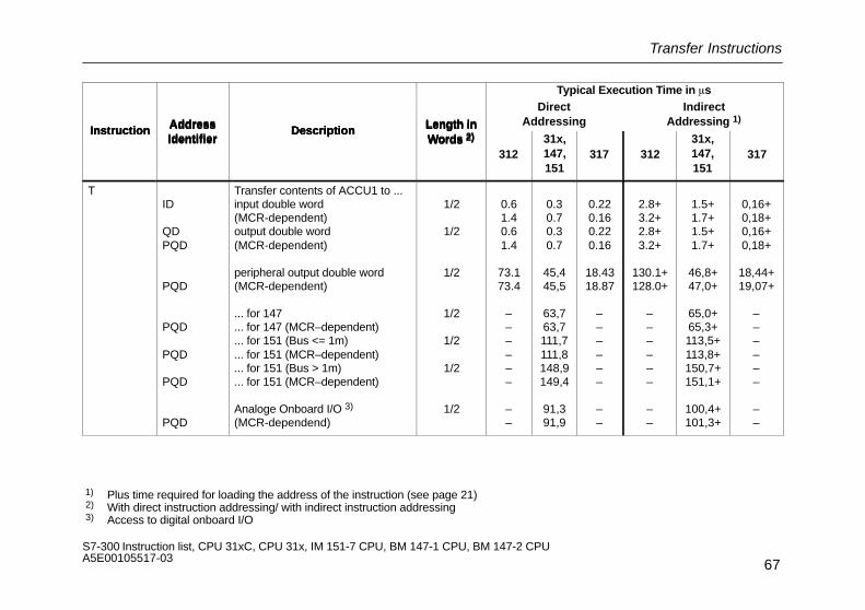
TID
QDPQD
PQD
PQD
PQD
PQD
PQD
Transfer contents of ACCU1 to ...input double word(MCR-dependent)output double word(MCR-dependent)
peripheral output double word(MCR-dependent)
... for 147
... for 147 (MCR–dependent)
... for 151 (Bus <= 1m)
... for 151 (MCR–dependent)
... for 151 (Bus > 1m)
... for 151 (MCR–dependent)
Analoge Onboard I/O 3)
(MCR-dependend)
1/2
1/2
1/2
1/2
1/2
1/2
1/2
0.61.40.61.4
73.173.4
––––––
––
0.30.70.30.7
45,445,5
63,763,7111,7111,8148,9149,4
91,391,9
0.220.160.220.16
18.4318.87
––––––
––
2.8+3.2+2.8+3.2+
130.1+128.0+
––––––
––
1.5+1.7+1.5+1.7+
46,8+47,0+
65,0+65,3+113,5+113,8+150,7+151,1+
100,4+101,3+
0,16+0,18+0,16+0,18+
18,44+19,07+
––––––
––
1) Plus time required for loading the address of the instruction (see page 21) 2) With direct instruction addressing/ with indirect instruction addressing 3) Access to digital onboard I/O

Transfer Instructions
68S7-300 Instruction list, CPU 31xC, CPU 31x, IM 151-7 CPU, BM 147-1 CPU, BM 147-2 CPU A5E00105517-03
Typical Execution Time in �s
InstructionAddress
DescriptionLength in
DirectAddressing
IndirectAddressing 1)
InstructionAddressIdentifier
DescriptionLength inWords 2)
31231x,147,151
317 31231x,147,151
317
T MD
LD
DBD
DID
bit memory double word(MCR-dependent)local data double word(MCR-dependent)Data double word(MCR-dependend)Instanz data double word(MCR-dependend)
1/2
2
2
2
0.61.70.92.04.54.44.54.4
0.30.80.41.02.22.22.22.2
0,270,180,220,180,190,210,180,20
3.8+4.2+4.4+4.0+5.7+6.1+5.7+6.1+
2.0+2.3+2.4+2.1+3.0+3.3+3.0+3.3+
0,19+0,22+0,18+0,25+0,20+0,23+0,19+0,22+
T i[AR1,m]i[AR2,m]D[AR1,m]D[AR2,m]Parameter
Register-ind., area-internal (AR1)Register-ind., area -internal (AR2)Area-crossing (AR1)Area-crossing (AR2)Via parameter
22222
–––––
–––––
–––––
+++++
+++++
+++++
1) Plus time required for loading the address of the instruction (see page 21) 2) With direct instruction addressing
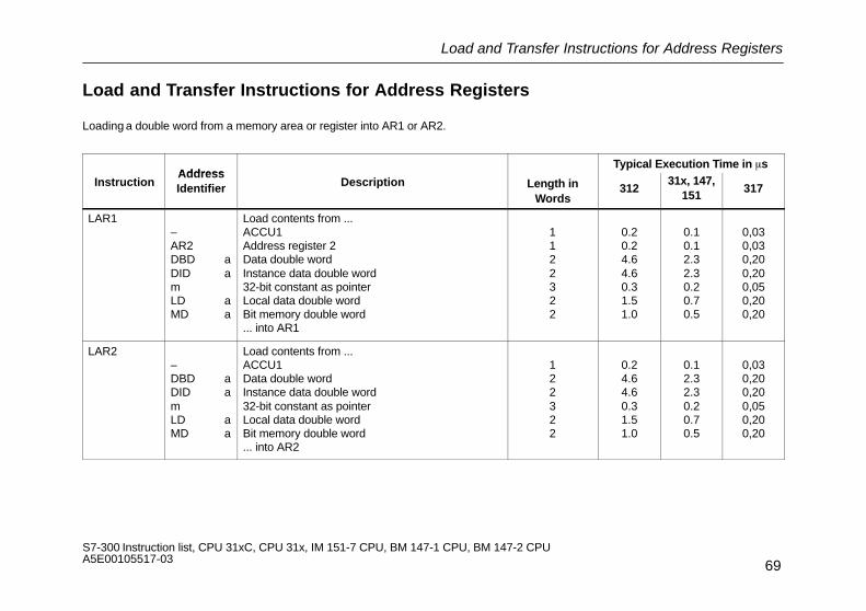
Load and Transfer Instructions for Address Registers
69S7-300 Instruction list, CPU 31xC, CPU 31x, IM 151-7 CPU, BM 147-1 CPU, BM 147-2 CPU A5E00105517-03
Load and Transfer Instructions for Address Registers
Loading a double word from a memory area or register into AR1 or AR2.
AddressTypical Execution Time in �s
InstructionAddressIdentifier Description Length in
Words312
31x, 147,151
317
LAR1–AR2DBD aDID amLD aMD a
Load contents from ...ACCU1Address register 2Data double wordInstance data double word32-bit constant as pointerLocal data double wordBit memory double word... into AR1
1122322
0.20.24.64.60.31.51.0
0.10.12.32.30.20.70.5
0,030,030,200,200,050,200,20
LAR2–DBD aDID amLD aMD a
Load contents from ...ACCU1Data double wordInstance data double word32-bit constant as pointerLocal data double wordBit memory double word... into AR2
122322
0.24.64.60.31.51.0
0.12.32.30.20.70.5
0,030,200,200,050,200,20
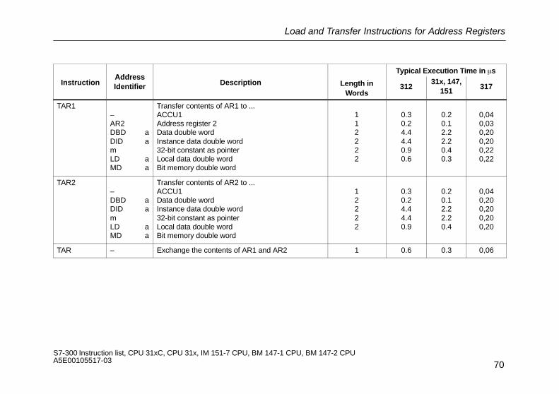
Load and Transfer Instructions for Address Registers
70S7-300 Instruction list, CPU 31xC, CPU 31x, IM 151-7 CPU, BM 147-1 CPU, BM 147-2 CPU A5E00105517-03
AddressTypical Execution Time in �s
InstructionAddressIdentifier Description Length in
Words312
31x, 147,151
317
TAR1–AR2DBD aDID amLD aMD a
Transfer contents of AR1 to ...ACCU1Address register 2Data double wordInstance data double word32-bit constant as pointerLocal data double wordBit memory double word
112222
0.30.24.44.40.90.6
0.20.12.22.20.40.3
0,040,030,200,200,220,22
TAR2–DBD aDID amLD aMD a
Transfer contents of AR2 to ...ACCU1Data double wordInstance data double word32-bit constant as pointerLocal data double wordBit memory double word
12222
0.30.24.44.40.9
0.20.12.22.20.4
0,040,200,200,200,20
TAR – Exchange the contents of AR1 and AR2 1 0.6 0.3 0,06

Load and Transfer Instructions for the Status Word
71S7-300 Instruction list, CPU 31xC, CPU 31x, IM 151-7 CPU, BM 147-1 CPU, BM 147-2 CPU A5E00105517-03
Load and Transfer Instructions for the Status Word
InstructionAddress
Description Length in Typical Execution Time in �sInstruction
AddressIdentifier
Description Length inWords 312 31x, 147, 151 317
L STW Load status word 1) into ACCU1 1.1 0.6 0,09
Status word for: L STW BR CC 1 CC 0 OV OS OR STA RLO FC
Instruction depends on: Yes Yes Yes Yes Yes 0 0 Yes 0
Instruction affects: – – – – – – – – –
T STW Transfer ACCU1 (bits 0 to 8) to the sta-tus word 1)
1.1 0.6 0,23
Status word for: T STW BR CC 1 CC 0 OV OS OR STA RLO FC
Instruction depends on: – – – – – – – – –
Instruction affects: Yes Yes Yes Yes Yes – – Yes –
1) For the structure of the status word see page 15

Load Instructions for DB Number and DB Length
72S7-300 Instruction list, CPU 31xC, CPU 31x, IM 151-7 CPU, BM 147-1 CPU, BM 147-2 CPU A5E00105517-03
Load Instructions for DB Number and DB Length
Loading the number/length of a data block into ACCU1. The old contents of ACCU1 are saved to ACCU2. The condition code bits are notaffected.
InstructionAddress
Description Length in Typical Execution Time in �sInstruction
AddressIdentifier
Description Length inWords 312 31x, 147, 151 317
L DBNO Load number of data block 1 2.4 1.3 0,18
L DINO Load number of instance data block 1 2.4 1.3 0,18
L DBLG Load length of data block into byte 1 0.5 0.3 0,04
L DILG Load length of instance data block intobyte
1 0.5 0.3 0,04

Integer Math (16 Bits)
73S7-300 Instruction list, CPU 31xC, CPU 31x, IM 151-7 CPU, BM 147-1 CPU, BM 147-2 CPU A5E00105517-03
Integer Math (16 Bits)
Math instructions on two 16-bit words. The result is in ACCU1 and ACCU1-L, resp.
Address Length inTypical Execution Time in �s
InstructionAddressIdentifier Description
Length inWords 312
31x, 147,151
317
+I – Add 2 integers (16 bits)(ACCU1-L)=(ACCU1-L)+ (ACCU2-L)
1 1.3 0.6 0,20
–I – Subtract 1 integer from another (16 bits)(ACCU1-L)=(ACCU2-L)– (ACCU1-L)
1 1.5 0.7 0,17
*I – Multiply 1 integer by another (16 bits)(ACCU1)=(ACCU2-L)* (ACCU1-L)
1 2.2 1.1 0,22
/I – Divide 1 integer by another (16 bits)(ACCU1-L)= (ACCU2-L):(ACCU1-L)The remainder is in ACCU1-H
1 2.6 1.3 0,35
Status word for: +I, –I,*I, /I BR CC 1 CC 0 OV OS OR STA RLO FC
Instruction depends on: – – – – – – – – –
Instruction affects: – Yes Yes Yes Yes – – – –

Integer Math (32 Bits)
74S7-300 Instruction list, CPU 31xC, CPU 31x, IM 151-7 CPU, BM 147-1 CPU, BM 147-2 CPU A5E00105517-03
Integer Math (32 Bits)
Math instructions on two 32-bit words. The result is in ACCU1.
Address Length inTypical Execution Time in �s
InstructionAddressIdentifier Description
Length inWords 312
31x, 147,151
317
+D – Add 2 integers (32 bits)(ACCU1)=(ACCU2)+ (ACCU1)
1 1.6 0.8 0,16
–D – Subtract 1 integer from another (32 bits)(ACCU1)=(ACCU2)– (ACCU1)
1 2.2 1.1 0,18
*D – Multiply 1 integer by another (32 bits)(ACCU1)=(ACCU2)* (ACCU1)
1 7.1 3.5 0,17
/D – Divide 1 integer by another (32 bits)(ACCU1)=(ACCU2): (ACCU1)
1 5.7 2.8 0,43
MOD – Divide 1 integer by another (32 bits) and load theremainder into ACCU1:(ACCU1)=remainder of [(ACCU2):(ACCU1)]
1 3.8 1.9 0,15
Status word for: +D, –D,*D, /D, MOD BR CC 1 CC 0 OV OS OR STA RLO FC
Instruction depends on: – – – – – – – – –
Instruction affects: – Yes Yes Yes Yes – – – –

Floating-Point Math (32 Bits)
75S7-300 Instruction list, CPU 31xC, CPU 31x, IM 151-7 CPU, BM 147-1 CPU, BM 147-2 CPU A5E00105517-03
Floating-Point Math (32 Bits)
The result of the math instruction is in ACCU1. The execution time of the instruction depends on the value to be calculated.
AddressTypical Execution Time in �s
InstructionAddressIdentifier Description Length in
Words312
31x, 147,151
317
+R – Add 2 real numbers (32 bits)(ACCU1)=(ACCU2)+(ACCU1)
1 5.5 2.7 0,98
–R – Subtract 1 real number from another (32 bits)(ACCU1)=(ACCU2)–(ACCU1)
1 5.5 2.7 0,98
*R – Multiply 1 real number by another (32 bits)(ACCU1)=(ACCU2)*(ACCU1)
1 6.4 3.2 0,55
/R – Divide 1 real number by another (32 bits)(ACCU1)=(ACCU2):(ACCU1)
1 6.1 3.0 1,46
Status word for: +R, –R, *R, /R BR CC 1 CC 0 OV OS OR STA RLO FC
Instruction depends on: – – – – – – – – –
Instruction affects: – Yes Yes Yes Yes – – – –
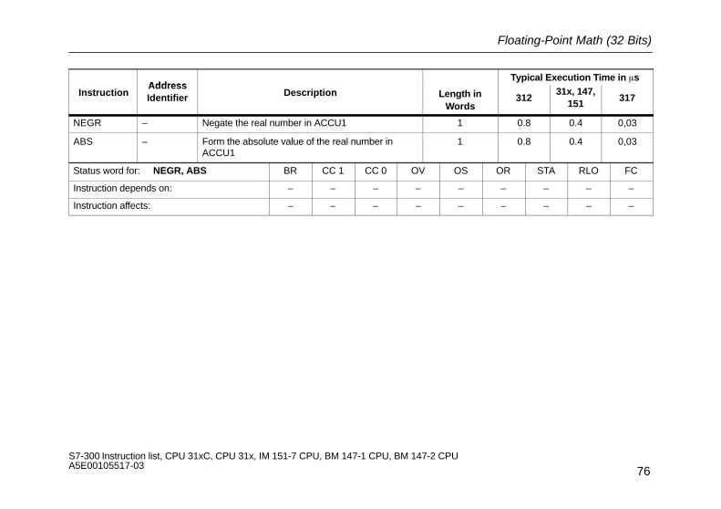
Floating-Point Math (32 Bits)
76S7-300 Instruction list, CPU 31xC, CPU 31x, IM 151-7 CPU, BM 147-1 CPU, BM 147-2 CPU A5E00105517-03
AddressTypical Execution Time in �s
InstructionAddressIdentifier Description Length in
Words312
31x, 147,151
317
NEGR – Negate the real number in ACCU1 1 0.8 0.4 0,03
ABS – Form the absolute value of the real number inACCU1
1 0.8 0.4 0,03
Status word for: NEGR, ABS BR CC 1 CC 0 OV OS OR STA RLO FC
Instruction depends on: – – – – – – – – –
Instruction affects: – – – – – – – – –
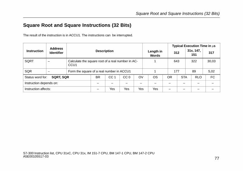
Square Root and Square Instructions (32 Bits)
77S7-300 Instruction list, CPU 31xC, CPU 31x, IM 151-7 CPU, BM 147-1 CPU, BM 147-2 CPU A5E00105517-03
Square Root and Square Instructions (32 Bits)
The result of the instruction is in ACCU1. The instructions can be interrupted.
AddressTypical Execution Time in �s
InstructionAddressIdentifier Description Length in
Words312
31x, 147,151
317
SQRT – Calculate the square root of a real number in AC-CCU1
1 643 322 30,03
SQR – Form the square of a real number in ACCU1 1 177 89 5,02
Status word for: SQRT, SQR BR CC 1 CC 0 OV OS OR STA RLO FC
Instruction depends on: – – – – – – – – –
Instruction affects: – Yes Yes Yes Yes – – – –

Logarithmic Function (32 Bits)
78S7-300 Instruction list, CPU 31xC, CPU 31x, IM 151-7 CPU, BM 147-1 CPU, BM 147-2 CPU A5E00105517-03
Logarithmic Function (32 Bits)
The result of the logarithmic function is in ACCU1. The instructions can be interrupted.
Address Length inTypical Execution Time in �s
InstructionAddressIdentifier Description
Length inWords 312
31x, 147,151
317
LN – Form the natural logarithm of a real number inACCU1
1 455 227 14,97
EXP – Calculate the exponential value of a real number inACCU1 to the base e (= 2.71828)
1 898 449 33,71
Status word for: LN, EXP BR CC 1 CC 0 OV OS OR STA RLO FC
Instruction depends on: – – – – – – – – –
Instruction affects: – Yes Yes Yes Yes – – – –
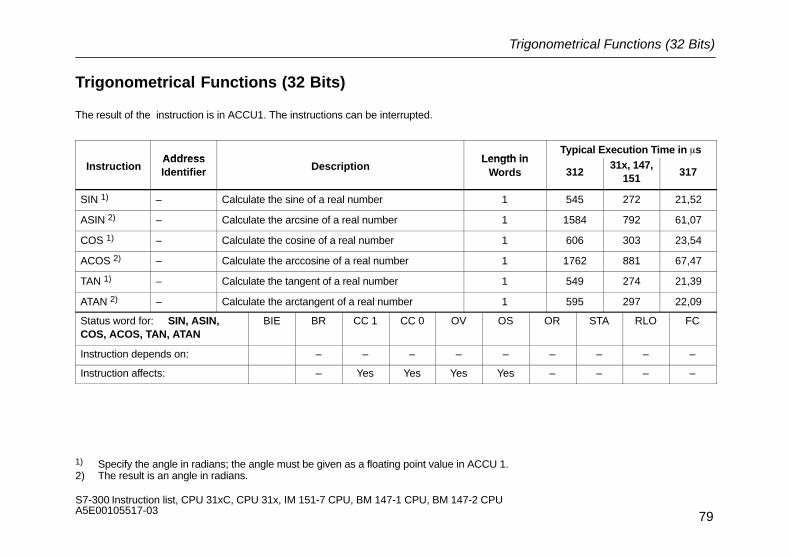
Trigonometrical Functions (32 Bits)
79S7-300 Instruction list, CPU 31xC, CPU 31x, IM 151-7 CPU, BM 147-1 CPU, BM 147-2 CPU A5E00105517-03
Trigonometrical Functions (32 Bits)
The result of the instruction is in ACCU1. The instructions can be interrupted.
Address Length inTypical Execution Time in �s
InstructionAddressIdentifier Description
Length inWords 312
31x, 147,151
317
SIN 1) – Calculate the sine of a real number 1 545 272 21,52
ASIN 2) – Calculate the arcsine of a real number 1 1584 792 61,07
COS 1) – Calculate the cosine of a real number 1 606 303 23,54
ACOS 2) – Calculate the arccosine of a real number 1 1762 881 67,47
TAN 1) – Calculate the tangent of a real number 1 549 274 21,39
ATAN 2) – Calculate the arctangent of a real number 1 595 297 22,09
Status word for: SIN, ASIN,COS, ACOS, TAN, ATAN
BIE BR CC 1 CC 0 OV OS OR STA RLO FC
Instruction depends on: – – – – – – – – –
Instruction affects: – Yes Yes Yes Yes – – – –
1) Specify the angle in radians; the angle must be given as a floating point value in ACCU 1.2) The result is an angle in radians.

Adding Constants
80S7-300 Instruction list, CPU 31xC, CPU 31x, IM 151-7 CPU, BM 147-1 CPU, BM 147-2 CPU A5E00105517-03
Adding Constants
Adding integer constants and storing the result in ACCU1. The condition code bits are not affected.
AddressTypical Execution Time in �s
InstructionAddressIdentifier Description Length in
Words312
31x, 147,151
317
+ i8 Add an 8-bit integer constant 1 0.2 0.1 0,08
+ i16 Add a 16-bit integer constant 2 0.2 0.1 0,08
+ i32 Add a 32-bit integer constant 3 0.3 0.2 0,08
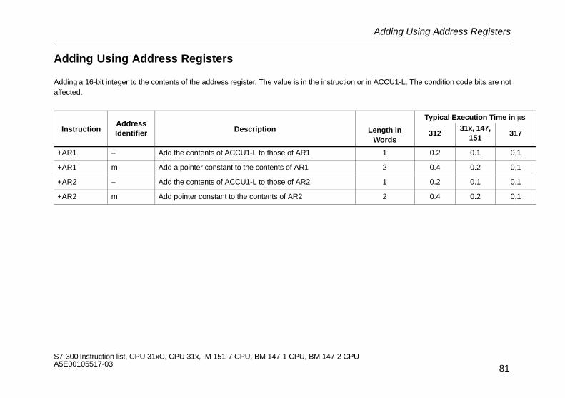
Adding Using Address Registers
81S7-300 Instruction list, CPU 31xC, CPU 31x, IM 151-7 CPU, BM 147-1 CPU, BM 147-2 CPU A5E00105517-03
Adding Using Address Registers
Adding a 16-bit integer to the contents of the address register. The value is in the instruction or in ACCU1-L. The condition code bits are notaffected.
AddressTypical Execution Time in �s
InstructionAddressIdentifier Description Length in
Words312
31x, 147,151
317
+AR1 – Add the contents of ACCU1-L to those of AR1 1 0.2 0.1 0,1
+AR1 m Add a pointer constant to the contents of AR1 2 0.4 0.2 0,1
+AR2 – Add the contents of ACCU1-L to those of AR2 1 0.2 0.1 0,1
+AR2 m Add pointer constant to the contents of AR2 2 0.4 0.2 0,1

Comparison Instructions with Integers (16 Bits)
82S7-300 Instruction list, CPU 31xC, CPU 31x, IM 151-7 CPU, BM 147-1 CPU, BM 147-2 CPU A5E00105517-03
Comparison Instructions with Integers (16 Bits)
Comparing the 16-bit integers in ACCU1-L and ACCU2-L. RLO = 1 if the condition is satisfied.
Address Length inTypical Execution Time in �s
IdentierAddress
Instruction DescriptionLength in
Words 31231x, 147,
151317
==I – ACCU2-L=ACCU1-L 1 1.4 0.7 0,14
<>I – ACCU2-L�ACCU1-L 1 1.6 0.8 0,14
<I – ACCU2-L<ACCU1-L 1 1.6 0.7 0,14
<=I – ACCU2-L<=ACCU1-L 1 1.4 0.7 0,14
>I – ACCU2-L>ACCU1-L 1 1.3 0.7 0,14
>=I – ACCU2-L>=ACCU1-L 1 1.4 0.7 0,14
Status word for: ==I, <>I, <I, <=I, >I, >=I BR CC 1 CC 0 OV OS OR STA RLO FC
Instruction depends on: – – – – – – – – –
Instruction affects: – Yes Yes 0 – 0 Yes Yes 1
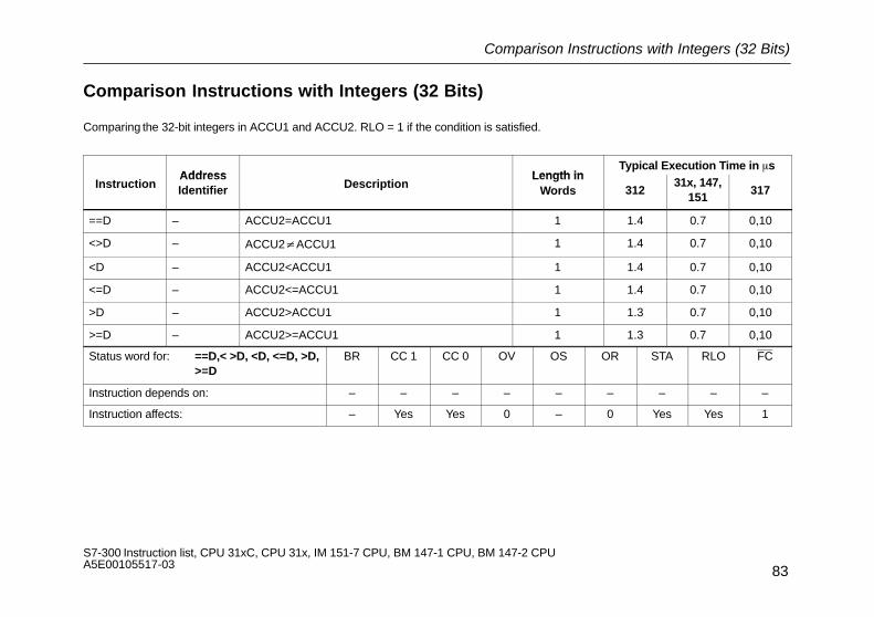
Comparison Instructions with Integers (32 Bits)
83S7-300 Instruction list, CPU 31xC, CPU 31x, IM 151-7 CPU, BM 147-1 CPU, BM 147-2 CPU A5E00105517-03
Comparison Instructions with Integers (32 Bits)
Comparing the 32-bit integers in ACCU1 and ACCU2. RLO = 1 if the condition is satisfied.
Address Length inTypical Execution Time in �s
InstructionAddressIdentifier Description
Length inWords 312
31x, 147,151
317
==D – ACCU2=ACCU1 1 1.4 0.7 0,10
<>D – ACCU2�ACCU1 1 1.4 0.7 0,10
<D – ACCU2<ACCU1 1 1.4 0.7 0,10
<=D – ACCU2<=ACCU1 1 1.4 0.7 0,10
>D – ACCU2>ACCU1 1 1.3 0.7 0,10
>=D – ACCU2>=ACCU1 1 1.3 0.7 0,10
Status word for: ==D,< >D, <D, <=D, >D,>=D
BR CC 1 CC 0 OV OS OR STA RLO FC
Instruction depends on: – – – – – – – – –
Instruction affects: – Yes Yes 0 – 0 Yes Yes 1

Comparison Instructions with Real Numbers (32 Bits)
84S7-300 Instruction list, CPU 31xC, CPU 31x, IM 151-7 CPU, BM 147-1 CPU, BM 147-2 CPU A5E00105517-03
Comparison Instructions with Real Numbers (32 Bits)
Comparing the 32-bit real numbers in ACCU1 and ACCU2. RLO = 1 if the condition is satisfied. The execution time of the instruction de-pends on the value to be compared.
Address Length inTypical Execution Time in �s
InstructionAddressIdentifier Description
Length inWords 312
31x, 147,151
317
== R – ACCU2=ACCU1 1 6.3 3.1 0,50
<> R – ACCU2�ACCU1 1 6.3 3.1 0,47
< R – ACCU2<ACCU1 1 6.4 3.2 0,47
< = R – ACCU2<=ACCU1 1 6.3 3.1 0,47
> R – ACCU2>ACCU1 1 6.3 3.1 0,49
> = R – ACCU2>=ACCU1 1 6.4 3.2 0,48
Status word for: ==R, <>R, <R, <=R, >R, >=R
BR CC 1 CC 0 OV OS OR STA RLO FC
Instruction depends on: – – – – – – – – –
Instruction affects: – Yes Yes Yes Yes 0 Yes Yes 1
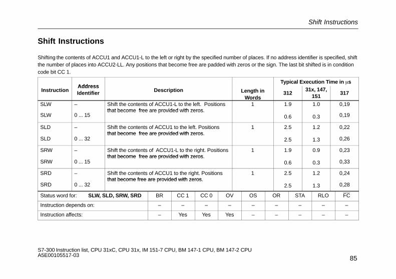
Shift Instructions
85S7-300 Instruction list, CPU 31xC, CPU 31x, IM 151-7 CPU, BM 147-1 CPU, BM 147-2 CPU A5E00105517-03
Shift Instructions
Shifting the contents of ACCU1 and ACCU1-L to the left or right by the specified number of places. If no address identifier is specified, shiftthe number of places into ACCU2-LL. Any positions that become free are padded with zeros or the sign. The last bit shifted is in conditioncode bit CC 1.
AddressTypical Execution Time in �s
InstructionAddressIdentifier Description Length in
Words312
31x, 147,151
317
SLW – Shift the contents of ACCU1-L to the left. Positionsthat become free are provided with zeros
1 1.9 1.0 0,19
SLW 0 ... 15that become free are provided with zeros.
0.6 0.3 0,19
SLD – Shift the contents of ACCU1 to the left. Positionsthat become free are provided with zeros
1 2.5 1.2 0,22
SLD 0 ... 32that become free are provided with zeros.
2.5 1.3 0,26
SRW – Shift the contents of ACCU1-L to the right. Positionsthat become free are provided with zeros
1 1.9 0.9 0,23
SRW 0 ... 15that become free are provided with zeros.
0.6 0.3 0,33
SRD – Shift the contents of ACCU1 to the right. Positionsthat become free are provided with zeros
1 2.5 1.2 0,24
SRD 0 ... 32that become free are provided with zeros.
2.5 1.3 0,28
Status word for: SLW, SLD, SRW, SRD BR CC 1 CC 0 OV OS OR STA RLO FC
Instruction depends on: – – – – – – – – –
Instruction affects: – Yes Yes Yes – – – – –
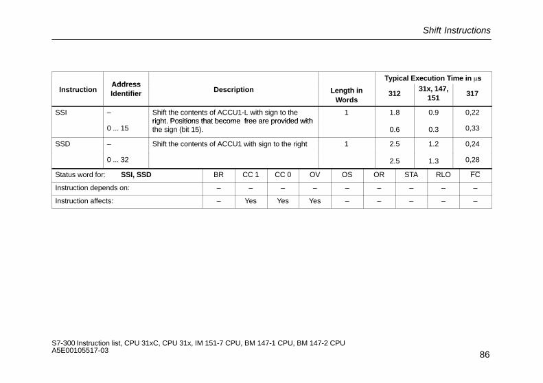
Shift Instructions
86S7-300 Instruction list, CPU 31xC, CPU 31x, IM 151-7 CPU, BM 147-1 CPU, BM 147-2 CPU A5E00105517-03
AddressTypical Execution Time in �s
InstructionAddressIdentifier Description Length in
Words312
31x, 147,151
317
SSI – Shift the contents of ACCU1-L with sign to theright Positions that become free are provided with
1 1.8 0.9 0,22
0 ... 15right. Positions that become free are provided withthe sign (bit 15). 0.6 0.3 0,33
SSD – Shift the contents of ACCU1 with sign to the right 1 2.5 1.2 0,24
0 ... 32 2.5 1.3 0,28
Status word for: SSI, SSD BR CC 1 CC 0 OV OS OR STA RLO FC
Instruction depends on: – – – – – – – – –
Instruction affects: – Yes Yes Yes – – – – –
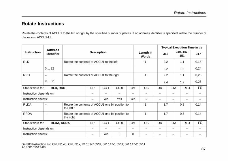
Rotate Instructions
87S7-300 Instruction list, CPU 31xC, CPU 31x, IM 151-7 CPU, BM 147-1 CPU, BM 147-2 CPU A5E00105517-03
Rotate Instructions
Rotate the contents of ACCU1 to the left or right by the specified number of places. If no address identifier is specified, rotate the number ofplaces into ACCU2-LL.
AddressTypical Execution Time in �s
InstructionAddressIdentifier Description Length in
Words312
31x, 147,151
317
RLD – Rotate the contents of ACCU1 to the left 1 2.2 1.1 0,18
0 ... 32 3.2 1.6 0,24
RRD – Rotate the contents of ACCU1 to the right 1 2.2 1.1 0,23
0 ... 32 2.4 1.2 0,28
Status word for: RLD, RRD BR CC 1 CC 0 OV OS OR STA RLO FC
Instruction depends on: – – – – – – – – –
Instruction affects: – Yes Yes Yes – – – – –
RLDA – Rotate the contents of ACCU1 one bit position tothe left t
1 1.7 0.8 0,14
RRDA – Rotate the contents of ACCU1 one bit position tothe right
1 1.7 0.8 0,14
Status word for: RLDA, RRDA BR CC 1 CC 0 OV OS OR STA RLO FC
Instruction depends on: – – – – – – – – –
Instruction affects: – Yes 0 0 – – – – –

Accumulator Transfer Instructions, Incrementing and Decrementing
88S7-300 Instruction list, CPU 31xC, CPU 31x, IM 151-7 CPU, BM 147-1 CPU, BM 147-2 CPU A5E00105517-03
Accumulator Transfer Instructions, Incrementing and Decrementing
The status word is not affected.
Address Length inTypical Execution Time in �s
InstructionAddressIdentifier Description
Length inWords 312
31x, 147,151
317
CAW – Reverse the order of the bytes in ACCU1-L.LL, LH becomes LH, LL.
1 0.2 0.1 0,10
CAD – Reverse the order of the bytes in ACCU1.LL, LH, HL, AA becomes HH, HL, LH, LL.
1 0.4 0.2 0,23
TAK – Swap the contents of ACCU1 and ACCU2 1 0.5 0.3 0,06
PUSH – The contents of ACCU1 are transferred to ACCU2. 1 0.2 0.1 0,03
POP – The contents of ACCU2 are transferred to ACCU1: 1 0.2 0.1 0,03
INC 0 ... 255 Increment ACCU1-LL 1 0.2 0.1 0,10
DEC 0 ... 255 Decrement ACCU1-LL 1 0.2 0.1 0,10

Program Display and Null Operation Instructions
89S7-300 Instruction list, CPU 31xC, CPU 31x, IM 151-7 CPU, BM 147-1 CPU, BM 147-2 CPU A5E00105517-03
Program Display and Null Operation Instructions
The status word is not affected.
AddressTypical Execution Time in �s
InstructionAddressIdentifier Description Length in
Words312
31x, 147,151
317
BLD 0 ... 255 Program display instruction:Is treated by the CPU like a null operation instruction.
1 0.2 0.1 0,040,04
NOP 01
Null Operation instruction: 1 0.20.2
0.10.1
0,040,04
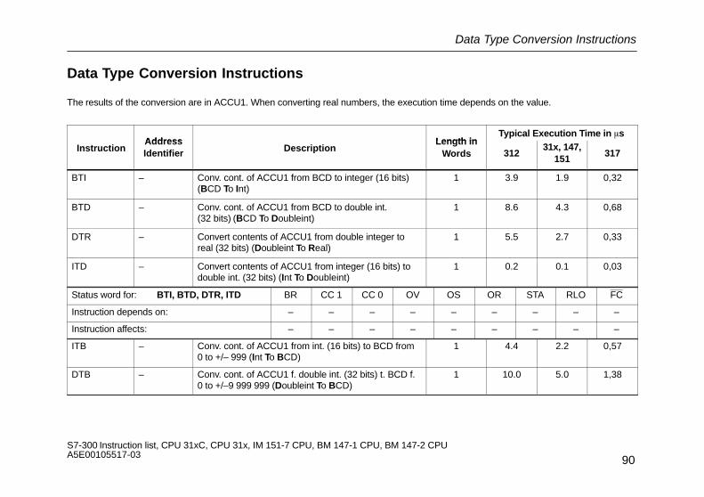
Data Type Conversion Instructions
90S7-300 Instruction list, CPU 31xC, CPU 31x, IM 151-7 CPU, BM 147-1 CPU, BM 147-2 CPU A5E00105517-03
Data Type Conversion Instructions
The results of the conversion are in ACCU1. When converting real numbers, the execution time depends on the value.
Address Length inTypical Execution Time in �s
InstructionAddressIdentifier Description
Length inWords 312
31x, 147,151
317
BTI – Conv. cont. of ACCU1 from BCD to integer (16 bits)(BCD To Int)
1 3.9 1.9 0,32
BTD – Conv. cont. of ACCU1 from BCD to double int.(32 bits) (BCD To Doubleint)
1 8.6 4.3 0,68
DTR – Convert contents of ACCU1 from double integer toreal (32 bits) (Doubleint To Real)
1 5.5 2.7 0,33
ITD – Convert contents of ACCU1 from integer (16 bits) todouble int. (32 bits) (Int To Doubleint)
1 0.2 0.1 0,03
Status word for: BTI, BTD, DTR, ITD BR CC 1 CC 0 OV OS OR STA RLO FC
Instruction depends on: – – – – – – – – –
Instruction affects: – – – – – – – – –
ITB – Conv. cont. of ACCU1 from int. (16 bits) to BCD from0 to +/– 999 (Int To BCD)
1 4.4 2.2 0,57
DTB – Conv. cont. of ACCU1 f. double int. (32 bits) t. BCD f.0 to +/–9 999 999 (Doubleint To BCD)
1 10.0 5.0 1,38

Data Type Conversion Instructions
91S7-300 Instruction list, CPU 31xC, CPU 31x, IM 151-7 CPU, BM 147-1 CPU, BM 147-2 CPU A5E00105517-03
Address Length inTypical Execution Time in �s
InstructionAddressIdentifier Description
Length inWords 312
31x, 147,151
317
RND – Convert a real number into a 32-bit integer. 1 6.5 3.2 0,41
RND– – Convert a real number into a 32-bit integer. The num-ber is
1 6.5 3.3 0,41
Status word for: ITB, DTB, RND, RND–, RND+,TRUNC
BR CC 1 CC 0 OV OS OR STA RLO FC
Instruction depends on: – – – – – – – – –
Instruction affects: – – – Yes Yes – – – –
RND+ – Convert a real number into a 32-bit integer. The num-ber is rounded to the next whole number.
1 6.7 3.3 0,42
TRUNC – Convert a real number into a 32-bit integer. The placesafter the decimal point are truncated.
1 6.3 3.1 0,41
Status word for: ITB, DTB, RND, RND–, RND+,TRUNC
BR CC 1 CC 0 OV OS OR STA RLO FC
Instruction depends on: – – – – – – – – –
Instruction affects: – – – Yes Yes – – – –

Forming the Ones and Twos Complements
92S7-300 Instruction list, CPU 31xC, CPU 31x, IM 151-7 CPU, BM 147-1 CPU, BM 147-2 CPU A5E00105517-03
Forming the Ones and Twos Complements
Address Length inTypical Execution Time in �s
InstructionAddressIdentifier Description
Length inWords 312
31x, 147,151
317
INVI – Form the ones complement of ACCU1-L 1 0.2 0.1 0,05
INVD – Form the ones complement of ACCU1 1 0.2 0.1 0,08
Status word for: INVI, INVD BR CC 1 CC 0 OV OS OR STA RLO FC
Instruction depends on: – – – – – – – – –
Instruction affects: – – – – – – – – –
NEGI – Form the twos complement of ACCU1-L (integer) 1 1.4 0.7 0,19
NEGD – Form the twos complement of ACCU1 (double integer) 1 1.6 0.8 0,16
Status word for: NEGI, NEGD BR CC 1 CC 0 OV OS OR STA RLO FC
Instruction depends on: – – – – – – – – –
Instruction affects: – Yes Yes Yes Yes – – – –

Block Call Instructions
93S7-300 Instruction list, CPU 31xC, CPU 31x, IM 151-7 CPU, BM 147-1 CPU, BM 147-2 CPU A5E00105517-03
Block Call Instructions
Typical Execution Time in �s
InstructionAddress
DescriptionLength
DirectAddressing
IndirectAddressing 1)
InstructionAddressIdentifier
DescriptionLength
in Words312
31x,147,151
317 31231x,147,151
317
CALL FB q,DB q
Unconditional call of an FB,with parameter transfer
1 16.4 8.8 – – – –
CALL SFB q,DB q
Unconditional call of an SFB,with parameter transfer
2 2) 2) – – – –
CALL FC q Unconditional call of a function,with parameter transfer
1 15.6 7.5 – – – –
CALL SFC q Unconditional call of an SFC,with parameter transfer
2 2 2 – – – –
Status word for: CALL BR CC 1 CC 0 OV OS OR STA RLO FC
Instruction depends on: – – – – – – – – –
Instruction affects: – – – – 0 0 1 – 0
1) Plus time required for loading the address of the instruction (see page 21) 2) See chapter System Functions (SFCs)/ see chapter System Function Blocks (SFBs)

Block Call Instructions
94S7-300 Instruction list, CPU 31xC, CPU 31x, IM 151-7 CPU, BM 147-1 CPU, BM 147-2 CPU A5E00105517-03
Typical Execution Time in �s
InstructionAddress
DescriptionLength
DirectAddressing
IndirectAddressing 1)
InstructionAddressIdentifier
DescriptionLength
in Words312
31x,147,151
317 31231x,147,151
317
UC FB qFC qParameter
Unconditional call of blocks without para-meter transferFB/FC call via parameter
13) 9.19.19.1
6.06.06.0
1,471,55
9.8+9.8+9.8+
6.4+6.4+6.4+
1,63+1,70+
CC FB qFC qParameter
Conditional call of blocks without para-meter transferFB/FC call via parameter
13) 9.49.49.4
6.26.26.2
1,531,59
9.9+9.9+9.9+
6.6+6.6+6.6+
1,65+1,73+
Status word for: UC, CC BR CC 1 CC 0 OV OS OR STA RLO FC
Instruction depends on: – – – – – – – – –
Instruction affects: – – – – 0 0 1 – 0
OPNDB qDI qParameter
Open:Data blockInstance data blockData block using parameters
1/22)
22
0.7 0.7 0,15 1.2+ 1.2+ 0,25+
Status word for: OPN BR CC 1 CC 0 OV OS OR STA RLO FC
Instruction depends on: – – – – – – – – –
Instruction affects: – – – – – – – – –
1) Plus time required for loading the address of the instruction (see page 21)2) Block No. > 2553) With direct instruction addressing

Block End Instructions
95S7-300 Instruction list, CPU 31xC, CPU 31x, IM 151-7 CPU, BM 147-1 CPU, BM 147-2 CPU A5E00105517-03
Block End Instructions
Address Length inTypical Execution Time in �s
InstructionAddressIdentifier Description
Length inWords 312
31x, 147,151
317
BE – End block 1 4.4 2.2 0,05
BEU – End block unconditionally 1 4.4 2.2 0,05
Status word for: BE, BEU BR CC 1 CC 0 OV OS OR STA RLO FC
Instruction depends on: – – – – – – – – –
Instruction affects: – – – – 0 0 1 – 0
BEC – End block conditionally if RLO = “1” 1 1.2 0.6 0,14
Status word for: BEC BR CC 1 CC 0 OV OS OR STA RLO FC
Instruction depends on: – – – – – – – Yes –
Instruction affects: – – – – Yes 0 1 1 0

Exchanging Shared Data Block and Instance Data Block
96S7-300 Instruction list, CPU 31xC, CPU 31x, IM 151-7 CPU, BM 147-1 CPU, BM 147-2 CPU A5E00105517-03
Exchanging Shared Data Block and Instance Data Block
Exchanging the two current data blocks. The current shared data block becomes the current instance data block, and vice versa. The con-dition code bits are not affected.
InstructionAddress
DescriptionLength in
Typical Execution Time in �s
InstructionAddressIdentifier
DescriptionLength in
Words 31231x, 147,
151317
CDB Exchange shared data block and instance data block 1 0.2 0.1 0,18
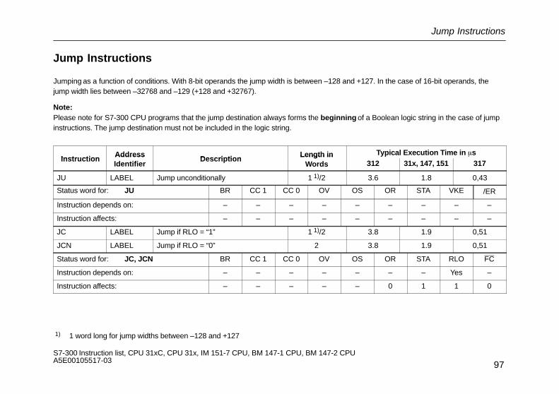
Jump Instructions
97S7-300 Instruction list, CPU 31xC, CPU 31x, IM 151-7 CPU, BM 147-1 CPU, BM 147-2 CPU A5E00105517-03
Jump Instructions
Jumping as a function of conditions. With 8-bit operands the jump width is between –128 and +127. In the case of 16-bit operands, thejump width lies between –32768 and –129 (+128 and +32767).
Note:Please note for S7-300 CPU programs that the jump destination always forms the beginning of a Boolean logic string in the case of jumpinstructions. The jump destination must not be included in the logic string.
InstructionAddress
DescriptionLength in Typical Execution Time in �s
InstructionAddressIdentifier
DescriptionLength in
Words 312 31x, 147, 151 317
JU LABEL Jump unconditionally 1 1)/2 3.6 1.8 0,43
Status word for: JU BR CC 1 CC 0 OV OS OR STA VKE /ER
Instruction depends on: – – – – – – – – –
Instruction affects: – – – – – – – – –
JC LABEL Jump if RLO = “1” 1 1)/2 3.8 1.9 0,51
JCN LABEL Jump if RLO = “0” 2 3.8 1.9 0,51
Status word for: JC, JCN BR CC 1 CC 0 OV OS OR STA RLO FC
Instruction depends on: – – – – – – – Yes –
Instruction affects: – – – – – 0 1 1 0
1) 1 word long for jump widths between –128 and +127

Jump Instructions
98S7-300 Instruction list, CPU 31xC, CPU 31x, IM 151-7 CPU, BM 147-1 CPU, BM 147-2 CPU A5E00105517-03
InstructionAddress
DescriptionLength in Typical Execution Time in �s
InstructionAddressIdentifier
DescriptionLength in
Words 312 31x, 147, 151 317
JCB LABEL Jump if RLO = “1”.Save the RLO in the BR bit
2 3.8 1.9 0,51
JNB LABEL Jump if RLO = “0”.Save the RLO in the BR bit
2 3.8 1.9 0,51
Status word for: JCB, JNB BR CC 1 CC 0 OV OS OR STA RLO FC
Instruction depends on: – – – – – – – Yes –
Instruction affects: Yes – – – – 0 1 1 0
JBI LABEL Jump if BR = “1” 2 3.8 1.9 0,51
JNBI LABEL Jump if BR = “0” 2 3.8 1.9 0,51
Status word for: JBI, JNBI BR CC 1 CC 0 OV OS OR STA RLO FC
Instruction depends on: Yes – – – – – – – –
Instruction affects: – – – – – 0 1 – 0
JO LABEL Jump on stored overflow (OV = “1”) 1 1)/2 3.8 1.9 0,51
Status word for: JO BR CC 1 CC 0 OV OS OR STA RLO FC
Instruction depends on: – – – Yes – – – – –
Instruction affects: – – – – – – – – –
1) 1 word long for jump widths between –128 and +127
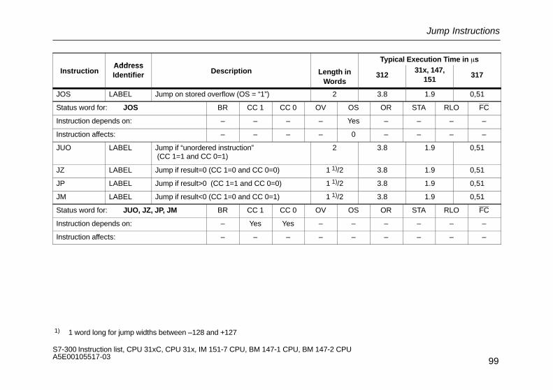
Jump Instructions
99S7-300 Instruction list, CPU 31xC, CPU 31x, IM 151-7 CPU, BM 147-1 CPU, BM 147-2 CPU A5E00105517-03
AddressTypical Execution Time in �s
InstructionAddressIdentifier Description Length in
Words312
31x, 147,151
317
JOS LABEL Jump on stored overflow (OS = “1”) 2 3.8 1.9 0,51
Status word for: JOS BR CC 1 CC 0 OV OS OR STA RLO FC
Instruction depends on: – – – – Yes – – – –
Instruction affects: – – – – 0 – – – –
JUO LABEL Jump if “unordered instruction” (CC 1=1 and CC 0=1)
2 3.8 1.9 0,51
JZ LABEL Jump if result=0 (CC 1=0 and CC 0=0) 1 1)/2 3.8 1.9 0,51
JP LABEL Jump if result>0 (CC 1=1 and CC 0=0) 1 1)/2 3.8 1.9 0,51
JM LABEL Jump if result<0 (CC 1=0 and CC 0=1) 1 1)/2 3.8 1.9 0,51
Status word for: JUO, JZ, JP, JM BR CC 1 CC 0 OV OS OR STA RLO FC
Instruction depends on: – Yes Yes – – – – – –
Instruction affects: – – – – – – – – –
1) 1 word long for jump widths between –128 and +127

Jump Instructions
100S7-300 Instruction list, CPU 31xC, CPU 31x, IM 151-7 CPU, BM 147-1 CPU, BM 147-2 CPU A5E00105517-03
AddressTypical Execution Time in �s
InstructionAddressIdentifier Description Length in
Words312
31x, 147,151
317
JN LABEL Jump if result�0 (CC 1=1 and CC 0=0) or (CC 1=0)and (CC 0=1)
1 1)/2 3.8 1.9 0,51
JMZ LABEL Jump if result�0 (CC 1=0 and CC 0=1) or (CC 1=0and CC 0=0)
2 3.8 1.9 0,51
JPZ LABEL Jump if result�0 (CC 1=1 and CC 0=0) or (CC 1=0)and (CC 0=0)
2 3.8 1.9 0,51
Status word for: JN, JMZ, JPZ BR CC 1 CC 0 OV OS OR STA RLO FC
Instruction depends on: – Yes Yes – – – – – –
Instruction affects: – – – – – – – – –
JL LABEL Jump distributorThis instruction is followed by a list of jump instructions.The operand is a jump label to subsequent instructions in this list.ACCU1-L contains the number of the jump instruction to be executed.
2 5.0 2.5 0,78
LOOP LABEL Decrement ACCU1-L and jump if ACCU1-L�0(loop programming)
2 3.5 1.8 0,30
Status word for: JL, LOOP BR CC 1 CC 0 OV OS OR STA RLO FC
Instruction depends on: – – – – – – – – –
Instruction affects: – – – – – – – – – 1) 1 word long for jump widths between –128 and +127
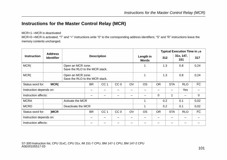
Instructions for the Master Control Relay (MCR)
101S7-300 Instruction list, CPU 31xC, CPU 31x, IM 151-7 CPU, BM 147-1 CPU, BM 147-2 CPU A5E00105517-03
Instructions for the Master Control Relay (MCR)
MCR=1�MCR is deactivatedMCR=0�MCR is activated; “T” and “=” instructions write “0” to the corresponding address identifiers; “S” and “R” instructions leave thememory contents unchanged.
AddressTypical Execution Time in �s
InstructionAddressIdentifier Description Length in
Words312
31x, 147,151
317
MCR( Open an MCR zone.Save the RLO to the MCR stack.
1 1.3 0.8 0,24
MCR( Open an MCR zone.Save the RLO to the MCR stack.
1 1.3 0.8 0,24
Status word for: MCR( BR CC 1 CC 0 OV OS OR STA RLO FC
Instruction depends on: – – – – – – – Yes –
Instruction affects: – – – – – 0 1 – 0
MCRA Activate the MCR 1 0.2 0.1 0,02
MCRD Deactivate the MCR 1 0.2 0.1 0,02
Status word for: )MCR BR CC 1 CC 0 OV OS OR STA RLO FC
Instruction depends on: – – – – – – – – –
Instruction affects: – – – – – – – – –

Organisation Blocks (OB)
102S7-300 Instruction list, CPU 31xC, CPU 31x, IM 151-7 CPU, BM 147-1 CPU, BM 147-2 CPU A5E00105517-03
Organisation Blocks (OB)
A user program for an S7-300 consists of blocks which contain the instructions, parameters, and data for the respective CPU. The indivi-dual CPUs of the S7-300 differ in the number of blocks which you can define for the respective CPU, and of those which are supplied bythe operating system of the CPU. You can find a detailed description of the OBs and their use in the STEP 7 online help system.
OrganisationBlocks
312 31x, 147, 151 317 Starting Events(Hexadecimal Values)
Cycle:
OB 1 x x x 1101H OB1 starting event1103H Running OB1 start event
(conclusion of the free cycle)
Time-of-day interrupt:
OB 10 x x x 1111H Time-of-day interrupt event
Delay Interrupt:
OB 20 x x x 1121H Delay interrupt event
OB 21 – – x 1122H Delay interrupt event

Organisation Blocks (OB)
103S7-300 Instruction list, CPU 31xC, CPU 31x, IM 151-7 CPU, BM 147-1 CPU, BM 147-2 CPU A5E00105517-03
OrganisationBlocks
Starting Events(Hexadecimal Values)
31731x, 147, 151312
Watchdog interrupt:
OB 32 – – x 1133H Watchdog interrupt event
OB 33 – – x 1134H Watchdog interrupt event
OB 34 – – x 1135H Watchdog interrupt event
OB 35 x x x 1136H Watchdog interrupt event
Process interrupt:
OB 40 x x x 1141H Process interrupt
DPV1-Interrupt (only DP-CPUs)
OB 55
OB 56
OB 57
–
–
–
x
x
x
x
x
x
1155H Status interrupt
1156H Update-interrupt
1157H Manufactur-specific interrupt
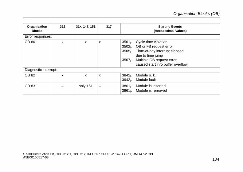
Organisation Blocks (OB)
104S7-300 Instruction list, CPU 31xC, CPU 31x, IM 151-7 CPU, BM 147-1 CPU, BM 147-2 CPU A5E00105517-03
OrganisationBlocks
Starting Events(Hexadecimal Values)
31731x, 147, 151312
Error responses:
OB 80 x x x 3501H Cycle time violation3502H OB or FB request error3505H Time-of-day interrupt elapsed
due to time jump3507H Multiple OB request error
caused start info buffer overflowDiagnostic interrupt:
OB 82 x x x 3842H Module o. k. 3942H Module fault
OB 83 – only 151 – 3861H Module is inserted3961H Module is removed
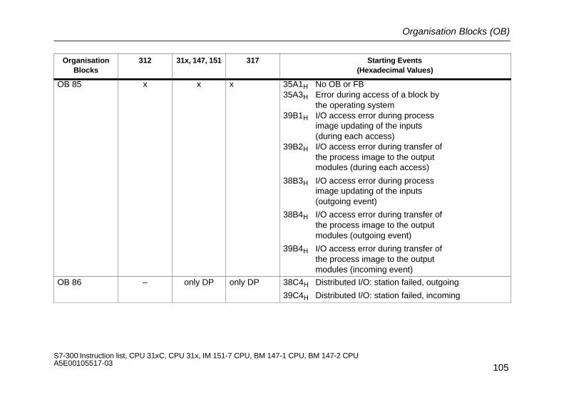
Organisation Blocks (OB)
105S7-300 Instruction list, CPU 31xC, CPU 31x, IM 151-7 CPU, BM 147-1 CPU, BM 147-2 CPU A5E00105517-03
OrganisationBlocks
312 31x, 147, 151 317 Starting Events(Hexadecimal Values)
OB 85 x x x 35A1H No OB or FB35A3H Error during access of a block by
the operating system39B1H I/O access error during process
image updating of the inputs(during each access)
39B2H I/O access error during transfer ofthe process image to the outputmodules (during each access)
38B3H I/O access error during processimage updating of the inputs(outgoing event)
38B4H I/O access error during transfer ofthe process image to the outputmodules (outgoing event)
39B4H I/O access error during transfer ofthe process image to the outputmodules (incoming event)
OB 86 – only DP only DP 38C4H Distributed I/O: station failed, outgoing
39C4H Distributed I/O: station failed, incoming
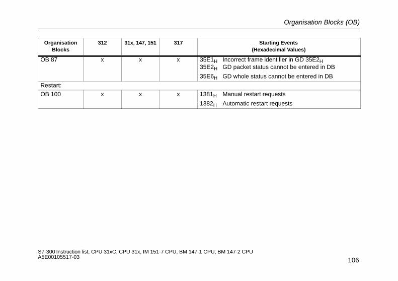
Organisation Blocks (OB)
106S7-300 Instruction list, CPU 31xC, CPU 31x, IM 151-7 CPU, BM 147-1 CPU, BM 147-2 CPU A5E00105517-03
OrganisationBlocks
312 31x, 147, 151 317 Starting Events(Hexadecimal Values)
OB 87 x x x 35E1H Incorrect frame identifier in GD 35E2H35E2H GD packet status cannot be entered in DB
35E6H GD whole status cannot be entered in DB
Restart:
OB 100 x x x 1381H Manual restart requests
1382H Automatic restart requests

Organisation Blocks (OB)
107S7-300 Instruction list, CPU 31xC, CPU 31x, IM 151-7 CPU, BM 147-1 CPU, BM 147-2 CPU A5E00105517-03
OrganisationBlocks
312 31x, 147, 151 317 Starting Events(Hexadecimal Values)
Synchronous error responses:
OB 121 x x x 2521H BCD conversion error
2522H Range length error during reading
2523H Range length error during writing
2524H Range error during reading
2525H Range error during writing
2526H Timer number error
2527H Counter number error
2528H Alignment error during reading
2529H Alignment error during writing
253AH DB not loaded
253CH FC not loaded
253EH FB not loadedOB 122 x x x 2944H I/O access error at nth read access (n > 1)
2945H I/O access error at nth write access (n > 1)

Function Blocks (FB)
108S7-300 Instruction list, CPU 31xC, CPU 31x, IM 151-7 CPU, BM 147-1 CPU, BM 147-2 CPU A5E00105517-03
Function Blocks (FB)
The following tables list the quantities, numbers, and maximal sizes of the function blocks, functions and data blocks that you can define inthe individual CPUs of the S7-300.
Blocks 31x, (except for 315-2 DP,
147, 151)
315-2 DP 317
Quantity 1) 512 2048 2048
Admissible numbers 0 to 511 0 to 2047 0 bis 2047
Maximal size of an FB (process-relevant code) 16 kB 16 kB 64 kByte
Functions (FC)
Blocks 31x(except for 315-2 DP,
147, 151)
315-2 DP 317
Quantity 1) 512 2048 2048
Admissible numbers 0 to 511 0 to 2047 0 bis 2047
Maximal size of an FC (process-relevant code) 16 kB 16 kB 64 kByte
1) Entire number FB, FC, DB: 1024CPU 317–2 DP:2048
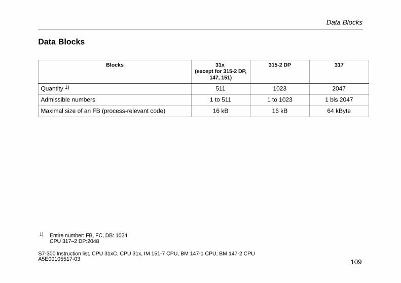
Data Blocks
109S7-300 Instruction list, CPU 31xC, CPU 31x, IM 151-7 CPU, BM 147-1 CPU, BM 147-2 CPU A5E00105517-03
Data Blocks
Blocks 31x (except for 315-2 DP,
147, 151)
315-2 DP 317
Quantity 1) 511 1023 2047
Admissible numbers 1 to 511 1 to 1023 1 bis 2047
Maximal size of an FB (process-relevant code) 16 kB 16 kB 64 kByte
1) Entire number: FB, FC, DB: 1024CPU 317–2 DP:2048

Memory required by the SFBs for the integrated inputs and outputs
110S7-300 Instruction list, CPU 31xC, CPU 31x, IM 151-7 CPU, BM 147-1 CPU, BM 147-2 CPU A5E00105517-03
Memory required by the SFBs for the integrated inputs and outputs
SFB Data Load memory Work memory (RAM)
41 CONT_C 126 330 162
42 CONT_S 90 266 126
43 PULSEGEN 34 168 70
44 ANALOG 98 316 134
46 DIGITAL 88 286 124
47 COUNT 34 178 70
48 FREQUENC 34 176 70
49 PULSE 24 138 60
60 SEND_PTP 40 290 76
61 RCV_PTP 44 298 80
62 RES_RCVB 28 272 64
63 SEND_RK 432 1074 468
64 FETCH_RK 432 1074 468
65 SERVE_RK 408 1032 444

System Functions (SFC)
111S7-300 Instruction list, CPU 31xC, CPU 31x, IM 151-7 CPU, BM 147-1 CPU, BM 147-2 CPU A5E00105517-03
System Functions (SFC)
The following tables show the system functions offered by the
operating systems of the S7-300 CPUs, and the execution times on the respective CPUs.
Execution Time in sSFCSFC Name Description
Execution Time in �sSFCNo. SFC Name Description
312 31x, 147, 151 317
0 SET_CLK Sets the clock time 235 195 44
1 READ_CLK Reads the clock time 70 60 17
2 SET_RTM Sets the operating hours counter 75 65 14
3 CTRL_RTM Starts/stops the operating hours counter 70 60 12
4 READ_RTM Reads the operating hours counter 105 90 16
5 GADR_LGC Determine logical channel address
Rack–0
Internal DP
160 135 23
6 RD_SINFO Reads start information of the current OB. 135 110 19
7 DP_PRAL 1) Triggers a process interrupt from the user programof the CPU as DP slave through to DP master.
– 90 19
11 SYC_FR 1) Synchronizes groups of DP slaves – 300 63
12 D_ACT_DP 1) Activates or deactivates DP slaves – 410 90 1) only CPU 31x-2 DP

System Functions (SFC)
112S7-300 Instruction list, CPU 31xC, CPU 31x, IM 151-7 CPU, BM 147-1 CPU, BM 147-2 CPU A5E00105517-03
Execution Time in �sSFCSFC Name Description
Execution Time in �sSFCNo. SFC Name Description
312 31x, 147, 151 317
13 DPNRM_DG1) Reads the DP-compliant slave diagnosis (CPU31) – 150 32
14 DPRD_DAT Reads/writes consistent data( b t )
– 150 30
15 DPWR_DAT (n bytes) – 150 32
17 ALARM_SQ Generates block-related messages that can beacknowledged
250 250 52
18 ALARM_S Generates block-related messages that can not beacknowledged
250 250 50
19 ALARM_SC Acknowledgment state of the last ALARM_SQreceived message
110 110 23
20 BLKMOV Copies variableswithin the working memory
90 �s + 2/Byte
75 �s + 1.6/Byte
16 �s + 0,05/
Byte
21 FILL Sets array default variableswithin the working memory
90 �s + 2.6/Byte
75 �s + 2.2/Byte
16 �s + 0,08/
Byte
22 CREAT_DB Generates a data block 110 �s +3.5/ DB
in the speci-fied areas
110 �s +3.5/ DB
in the speci-fied areas
23,1 �s +0,75/ DB
in the speci-fied areas
23 DEL_DB Deletes a data block 402 402 80
24 TEST_DB Tests a data block 130 110 18
1) only CPU 31x-2 DP

System Functions (SFC)
113S7-300 Instruction list, CPU 31xC, CPU 31x, IM 151-7 CPU, BM 147-1 CPU, BM 147-2 CPU A5E00105517-03
Execution Time in �sSFCSFC Name Description
Execution Time in �sSFCNo. SFC Name Description
312 31x, 147, 151 317
28 SET_TINT Sets the times of a time-of-day interrupt 190 160 40
29 CAN_TINT Cancels a time-of-day interrupt 85 70 2
30 ACT_TINT Activates a time-of-day interrupt 140 120 28
31 QRY_TINT Queries the status of a time–of-day interrupt 90 75 12
32 SRT_DINT Starts a delay interrupt 90 75 22
33 CAN_DINT Cancels a delay interrupt 60 50 11
34 QRY_DINT Queries started delay interrupts 85 71 13
36 MSK_FLT Masks sync faults 132 110 17
37 DMSK_FLT Enables sync faults 143 120 18
38 READ_ERR Reads event status register 140 120 18
39 DIS_IRT Disables the handling of new interrupts 180 155 64
40 EN_IRT Enables the handling of new interrupt events 125 105 3141 DIS_AIRT Delays the handling of interrupts 50 45 9
42 EN_AIRT Enables the handling of interrupts 55 45 943 RE_TRIGR Re-triggers the scan time monitor 50 40 2344 REPL_VAL Copies a substitute value into accumulator 60 50 3946 STP Forces the CPU into the STOP mode –
1) only CPU 31x-2 DP
1)

System Functions (SFC)
114S7-300 Instruction list, CPU 31xC, CPU 31x, IM 151-7 CPU, BM 147-1 CPU, BM 147-2 CPU A5E00105517-03
Execution Time in �sSFCSFC Name Description
Execution Time in �sSFCNo. SFC Name Description
312 31x, 147, 151 317
47 WAIT Delays program execution in addition to waitingtimes
250 250 198
49 LGC_GADR Converts a free address to the slot and rack for amodule
250 210 33
1) only CPU 31x-2 DP

System Functions (SFC)
115S7-300 Instruction list, CPU 31xC, CPU 31x, IM 151-7 CPU, BM 147-1 CPU, BM 147-2 CPU A5E00105517-03
SFCSFC Name Description
Execution Time in �sSFCNo. SFC Name Description
312 31x, 147, 151 317
50 RD_LGADR Reads all the declared free addresses for a module 500 420 59
51 RDSYSST Reads out the information from the system state list.SFC 51 is not interruptible through interrupts.
250�s + 10�spro byte
224�s + 10�spro byte
44�s + 2 �s
pro byte
52 WR_USMSG Writes specific diagnostic information in the diagno-stic buffer
280 235 66
55 WR_PARM Writes dynamic parameters to a module 2000 1700 349
56 WR_DPARM Writes predefined dynamic parameters to a module 1750 1750 346
57 PARM_MOD Assigns a module’s parameters <1650 <1400 <190
58 WR_REC Writes a module-specific data record 1400�s +32�s / byte
1400�s +32�s / byte
278�s +6,5�s
byte
59 RD_REC Reads a module-specific data record 500 500 98
64 TIME_TICK Reads out the system time 55 50 9
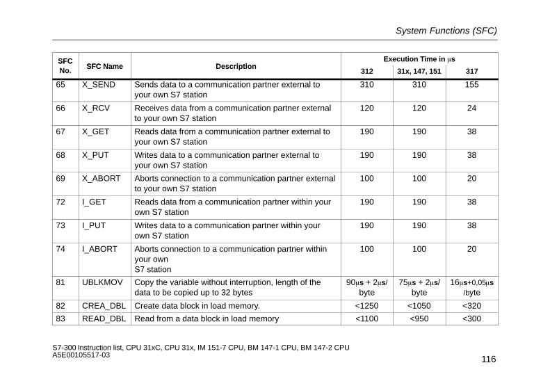
System Functions (SFC)
116S7-300 Instruction list, CPU 31xC, CPU 31x, IM 151-7 CPU, BM 147-1 CPU, BM 147-2 CPU A5E00105517-03
SFCSFC Name Description
Execution Time in �sSFCNo. SFC Name Description
312 31x, 147, 151 317
65 X_SEND Sends data to a communication partner external toyour own S7 station
310 310 155
66 X_RCV Receives data from a communication partner externalto your own S7 station
120 120 24
67 X_GET Reads data from a communication partner external toyour own S7 station
190 190 38
68 X_PUT Writes data to a communication partner external toyour own S7 station
190 190 38
69 X_ABORT Aborts connection to a communication partner externalto your own S7 station
100 100 20
72 I_GET Reads data from a communication partner within yourown S7 station
190 190 38
73 I_PUT Writes data to a communication partner within yourown S7 station
190 190 38
74 I_ABORT Aborts connection to a communication partner withinyour ownS7 station
100 100 20
81 UBLKMOV Copy the variable without interruption, length of thedata to be copied up to 32 bytes
90�s + 2�s/byte
75�s + 2�s/byte
16�s+0,05�s/byte
82 CREA_DBL Create data block in load memory. <1250 <1050 <320
83 READ_DBL Read from a data block in load memory <1100 <950 <300
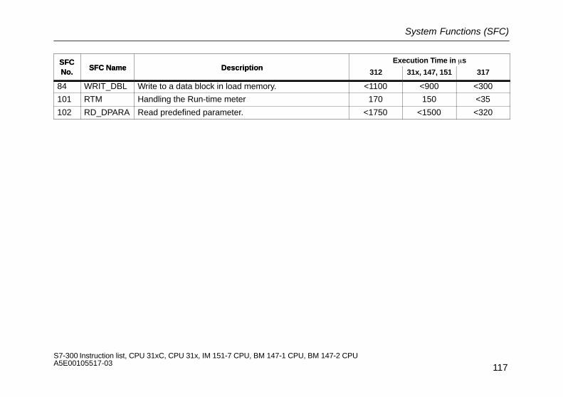
System Functions (SFC)
117S7-300 Instruction list, CPU 31xC, CPU 31x, IM 151-7 CPU, BM 147-1 CPU, BM 147-2 CPU A5E00105517-03
SFCNo.
Execution Time in �sDescriptionSFC Name
SFCNo. 31731x, 147, 151312
DescriptionSFC Name
84 WRIT_DBL Write to a data block in load memory. <1100 <900 <300
101 RTM Handling the Run-time meter 170 150 <35
102 RD_DPARA Read predefined parameter. <1750 <1500 <320

System Function Blocks (SFB)
118S7-300 Instruction list, CPU 31xC, CPU 31x, IM 151-7 CPU, BM 147-1 CPU, BM 147-2 CPU A5E00105517-03
System Function Blocks (SFB)
The following table lists the system function blocks supplied by the operating system of the S7-300’s CPUs, and the execution times on therespective CPUs.
SFBSFB Name Description
Execution Time in �sSFBNo. SFB Name Description
312 31x, 147, 151 317
0 CTU Counts up 101 90 19
1 CTD Counts down 101 90 19
2 CTUD Counts up and counts down 109 100 21
3 TP Generates a pulse 135 115 26
4 TON Delays a leading edge 120 101 20
5 TOF Delays a falling edge 120 100 21
32 DRUM Implements a sequence processor with a maximumof 16 s
90 80 16
SFBs for the integrated inputs/outputs (only CPU 31xC)
41 CONT_C Continuous control 3300 –
42 CONT_S Step control 2800 –
43 PULSEGEN Pulse generation 1500 –
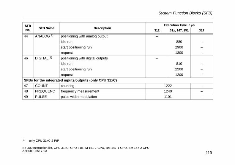
System Function Blocks (SFB)
119S7-300 Instruction list, CPU 31xC, CPU 31x, IM 151-7 CPU, BM 147-1 CPU, BM 147-2 CPU A5E00105517-03
SFBNo.
Execution Time in �sDescriptionSFB Name
SFBNo. 31731x, 147, 151312
DescriptionSFB Name
44 ANALOG 1) positioning with analog output
idle run
start positioning run
request
–
880
2900
1300
–
–
–
46 DIGITAL 1) positioning with digital outputs
idle run
start positioning run
request
–
810
2200
1200
–
–
–
SFBs for the integrated inputs/outputs (only CPU 31xC)
47 COUNT counting 1222 –
48 FREQUENC frequency measurement 1240 –
49 PULSE pulse width modulation 1101 –
1) only CPU 31xC-2 PtP
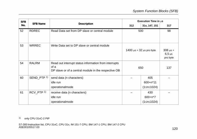
System Function Blocks (SFB)
120S7-300 Instruction list, CPU 31xC, CPU 31x, IM 151-7 CPU, BM 147-1 CPU, BM 147-2 CPU A5E00105517-03
SFBNo.
Execution Time in �sDescriptionSFB Name
SFBNo. 31731x, 147, 151312
DescriptionSFB Name
52 RDREC Read Data set from DP slave or central module 500 98
53 WRREC Write Data set to DP slave or central module
1400 �s + 32 �s pro byte 308 �s + 6,5 �s pro byte
54 RALRM Read out interrupt status information from interruptsof a DP slave or of a central module in the respective OB
650 137
60 SEND_PTP 1) send data (n characters)
idle run
operationalmode
– 405
600+n*11
(1≤n≤1024)
–
61 RCV_PTP 1) receive data (n characters)
idle run
operationalmode
– 430
600+n*7
(1≤n≤1024)
–
1) only CPU 31xC-2 PtP
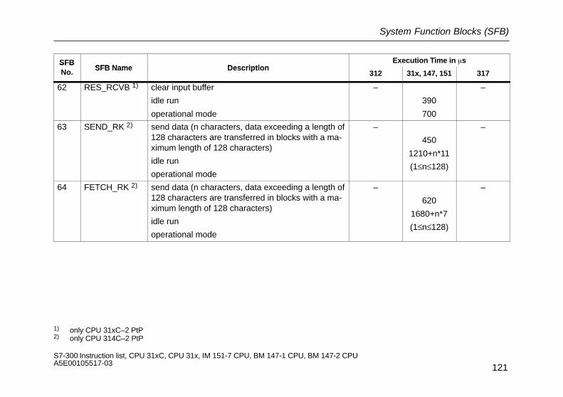
System Function Blocks (SFB)
121S7-300 Instruction list, CPU 31xC, CPU 31x, IM 151-7 CPU, BM 147-1 CPU, BM 147-2 CPU A5E00105517-03
SFBSFB Name Description
Execution Time in �sSFBNo. SFB Name Description
312 31x, 147, 151 317
62 RES_RCVB 1) clear input buffer
idle run
operational mode
–
390
700
–
63 SEND_RK 2) send data (n characters, data exceeding a length of128 characters are transferred in blocks with a ma-ximum length of 128 characters)
idle run
operational mode
–
450
1210+n*11
(1≤n≤128)
–
64 FETCH_RK 2) send data (n characters, data exceeding a length of128 characters are transferred in blocks with a ma-ximum length of 128 characters)
idle run
operational mode
–
620
1680+n*7
(1≤n≤128)
–
1) only CPU 31xC–2 PtP2) only CPU 314C–2 PtP
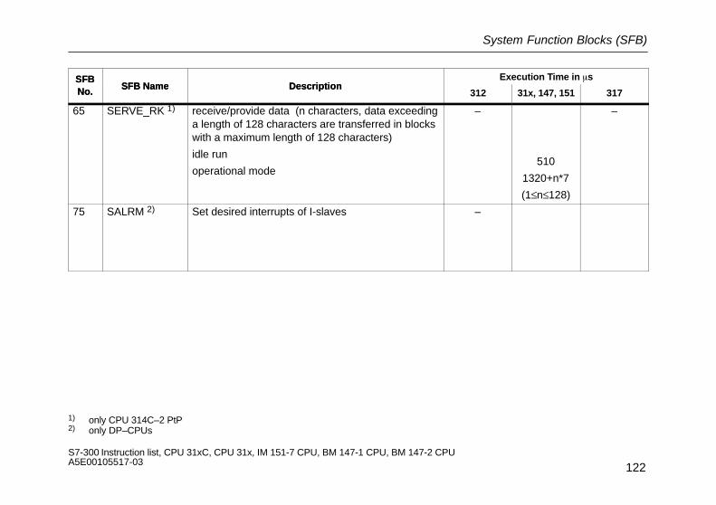
System Function Blocks (SFB)
122S7-300 Instruction list, CPU 31xC, CPU 31x, IM 151-7 CPU, BM 147-1 CPU, BM 147-2 CPU A5E00105517-03
SFBNo.
Execution Time in �sDescriptionSFB Name
SFBNo. 31731x, 147, 151312
DescriptionSFB Name
65 SERVE_RK 1) receive/provide data (n characters, data exceedinga length of 128 characters are transferred in blockswith a maximum length of 128 characters)
idle run
operational mode
–
510
1320+n*7
(1≤n≤128)
–
75 SALRM 2) Set desired interrupts of I-slaves –
1) only CPU 314C–2 PtP2) only DP–CPUs

IEC Functions
123S7-300 Instruction list, CPU 31xC, CPU 31x, IM 151-7 CPU, BM 147-1 CPU, BM 147-2 CPU A5E00105517-03
IEC Functions
You can use the following functions in STEP 7:
FCFC Name Description
FCNo.
FC Name Description
DATE_AND_TIME
3 D_TOD_DT Concatenates the data formats DATE and TIME_OF_DAY (TOD) and converts to data formatDATE_AND_TIME.
6 DT_DATE Extracts the DATE data format from the DATE_AND_TIME data format.
7 DT_DAY Extracts the day of the week from the data format DATE_AND_TIME.
8 DT_TOD Extracts the TIME_OF_DAY data format from the DATE_AND_TIME data format.
Time Formats
33 S5TI_TIM Converts S5 TIME data format to TIME data format
40 TIM_S5TI Converts TIME data format to S5 TIME data format
Duration
1 AD_DT_TM Adds a duration in the TIME format to a time in the DT format. The result is a new time in the DTformat.
35 SB_DT_TM Subtracts a duration in the TIME format from a time in the DT format. The result is a new time inthe DT format.
34 SB_DT_DT Subtracts two times in the DT format. The result is a duration in the TIME format.

IEC Functions
124S7-300 Instruction list, CPU 31xC, CPU 31x, IM 151-7 CPU, BM 147-1 CPU, BM 147-2 CPU A5E00105517-03
FCFC Name Description
FCNo.
FC Name Description
Compare DATE_AND_TIME
9 EQ_DT Compares the contents of two variables in the DATE_AND_TIME format for equal to.
12 GE_DT Compares the contents of two variables in the DATE_AND_TIME format for greater than or equalto.
14 GT_DT Compares the contents of two variables in the DATE_AND_TIME format for greater than.
18 LE_DT Compares the contents of two variables in the DATE_AND_TIME format for less than or equal to.
23 LT_DT Compares the contents of two variables in the DATE_AND_TIME format for less than.
28 NE_DT Compares the contents of two variables in the DATE_AND_TIME format for not equal to.
Compare STRING
10 EQ_STRNG Compares the contents of two variables in the STRING format for equal to.
13 GE_STRNG Compares the contents of two variables in the STRING format for greater than or equal to.
15 GT_STRNG Compares the contents of two variables in the STRING format for greater than.
19 LE_STRNG Compares the contents of two variables in the STRING format for less than or equal to.
24 LT_STRNG Compares the contents of two variables in the STRING format for less than.
29 NE_STRNG Compares the contents of two variables in the STRING format for not equal to.

IEC Functions
125S7-300 Instruction list, CPU 31xC, CPU 31x, IM 151-7 CPU, BM 147-1 CPU, BM 147-2 CPU A5E00105517-03
FC-FC Name Description
FC-Nr.
FC-Name Description
STRING Variable Processing
21 LEN Reads the length of a STRING variable.
20 LEFT Reads the first L characters of a STRING variable.
32 RIGHT Reads the last L characters of a STRING variable.
26 MID Reads the middle L characters of a STRING variable (starting at the defined character).
2 CONCAT Concatenates two STRING variables in one STRING variable.
17 INSERT Inserts a STRING variable into another STRING variable at a defined point.
4 DELETE Deletes L characters of a STRING variable.
31 REPLACE Replaces L characters of a STRING variable with a second STRING variable.
11 FIND Finds the position of the second STRING variable in the first STRING variable.

IEC Functions
126S7-300 Instruction list, CPU 31xC, CPU 31x, IM 151-7 CPU, BM 147-1 CPU, BM 147-2 CPU A5E00105517-03
FCFC Name Description
FCNo.
FC Name Description
Format Conversions with STRING
16 I_STRNG Converts a variable from INTEGER format to STRING format.
5 DI_STRNG Converts a variable from INTEGER (32-bit) format to STRING format.
30 R_STRNG Converts a variable from REAL format to STRING format.
38 STRNG_I Converts a variable from STRING format to INTEGER format.
37 STRNG_DI Converts a variable from STRING format to INTEGER (32-bit) format.
39 STRNG_R Converts a variable from STRING format to REAL format.
Number Processing
22 LIMIT Limits a number to a defined limit value.
25 MAX Selects the largest of three numeric variables.
27 MIN Selects the smallest of three numeric variables.
36 SEL Selects one of two variables.

System Status Sublist
127S7-300 Instruction list, CPU 31xC, CPU 31x, IM 151-7 CPU, BM 147-1 CPU, BM 147-2 CPU A5E00105517-03
System Status Sublist
SZL_ID Sublist Index(= ID of the individualrecords of the sublist)
Record Contents(Sublist Excerpt)
0111H
CPU identification
One record of the sublist 0001H
0006H
0007H
CPU type and version number
Indentification of the basic hardware
Identification of the basic firmware
0012H
0112H
0F12H
CPU features
All records of the sublist
Only those records of a group of features
Header information only
0000H
0100H
0300H
STEP 7 processing
Time system in the CPU
STEP 7 operation set
0013H User memory areas – Work memory

System Status Sublist
128S7-300 Instruction list, CPU 31xC, CPU 31x, IM 151-7 CPU, BM 147-1 CPU, BM 147-2 CPU A5E00105517-03
SZL_ID Record Contents(Sublist Excerpt)
Index(= ID of the individualrecords of the sublist)
Sublist
0014H Operating system areas – Process image of the inputs (number inbytes)
Process image of the outputs (number inbytes)
Number of memory markers
Number of timers
Number of counters
Size of the I/O address area
Entire local data area of the CPU (in by-tes)

System Status Sublist
129S7-300 Instruction list, CPU 31xC, CPU 31x, IM 151-7 CPU, BM 147-1 CPU, BM 147-2 CPU A5E00105517-03
SZL_ID Record Contents(Sublist Excerpt)
Index(= ID of the individualrecords of the sublist)
Sublist
0015H
Block types
All records of the sublist – OBs (number and size)
DBs (number and size)
SDBs (number and size)
FCs (number and size)
FBs (number and size)
0019H
0074H
0174H
0F19H
0F74H
State of module LEDs
Status of each LED
Header information only
0001H
0004H
0005H
0006H
0011H
–
SF-LED
RUN-LED
STOP-LED
FRCE-LED
BF-LED
011CH MMC copy protection 0008H serial number of MMC

System Status Sublist
130S7-300 Instruction list, CPU 31xC, CPU 31x, IM 151-7 CPU, BM 147-1 CPU, BM 147-2 CPU A5E00105517-03
SZL_ID Sublist Index(= ID of the individualrecords of the sublist)
Record Contents(Sublist Excerpt)
0132H Communications status on the communications type specified
0001H
0004H
0005H
0008H
000BH
000CH
Number and type of connections
CPU protection level, position of the key
switch, version identification of the user
program and configuration
Diagnostic status data
Target system, correction factor,
Run–time meter, Date/Time
Run–time meter (32 bits) 0 to 7
Run–time meter (32 bits) 8 to 15
0222H
Interrupt status
Record for the specified interrupt OB number –

System Status Sublist
131S7-300 Instruction list, CPU 31xC, CPU 31x, IM 151-7 CPU, BM 147-1 CPU, BM 147-2 CPU A5E00105517-03
SZL_ID Record Contents(Sublist Excerpt)
Index(= ID of the individualrecords of the sublist)
Sublist
0232H CPU Protection Level 0004H CPU protection level and position of thekey switch, version identification of theuser program and hardware configuration
0092H
0292H
0692H
Status information of module racks
Expected status of the module rack in
the central configuration
Actual status of module rack in
the central configuration
OK status of the expansion devices
in the central configuration
0000H Information about the status of the
module rack in the central configuration
0D91H Module status information of all modules in the specified rack (all CPUs)
0000H
0001H
0002H
0003H
Features/parameters of the moduleplugged in
Rack 0
Rack 1
Rack 2
Rack 3
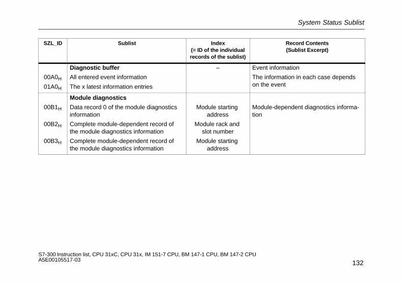
System Status Sublist
132S7-300 Instruction list, CPU 31xC, CPU 31x, IM 151-7 CPU, BM 147-1 CPU, BM 147-2 CPU A5E00105517-03
SZL_ID Sublist Index(= ID of the individualrecords of the sublist)
Record Contents(Sublist Excerpt)
00A0H
01A0H
Diagnostic buffer
All entered event information
The x latest information entries
– Event information
The information in each case dependson the event
00B1H
00B2H
00B3H
Module diagnostics
Data record 0 of the module diagnosticsinformation
Complete module-dependent record ofthe module diagnostics information
Complete module-dependent record ofthe module diagnostics information
Module starting address
Module rack and slot number
Module starting address
Module-dependent diagnostics informa-tion

PROFIBUS-DP Sublists
133S7-300 Instruction list, CPU 31xC, CPU 31x, IM 151-7 CPU, BM 147-1 CPU, BM 147-2 CPU A5E00105517-03
PROFIBUS-DP Sublists
SZL_ID Sublist Index(= ID of the individualrecords of the sublist)
Record Contents(Sublist Excerpt)
0A91H
0C91H
Module status information in the CPU
Status information of all DP subsystems andDP masters
Module status information of a module
Module starting address
Features/parameters of the moduleplugged in
0D91H
Module status information
In the station named (for CPU 315-2 DP) xxyyH All modules of station yy in the DPsubnet xx
As DP slave: Status data for transfermemory areas

PROFIBUS-DP Sublists
134S7-300 Instruction list, CPU 31xC, CPU 31x, IM 151-7 CPU, BM 147-1 CPU, BM 147-2 CPU A5E00105517-03
SZL_ID Record Contents(Sublist Excerpt)
Index(= ID of the individualrecords of the sublist)
Sublist
0092H
0292H
0692H
Status information of module racks orstations in the DP network
Target status of racks in central configura-tion or of stations in a subnet
Actual status of racks in central configura-tion or of stations in a subnet
OK status of expansion racks in central con-figuration or of stations in a subnet
0000H
DP-Mastersystem-ID
Information on the state of the mount-ing rack in the central configuration
Information of status of stations in sub-net
00B4H
Module diagnostics
All standard diagnostic data of a station(only with DP master)
Modulestart address(Diagnosticaddress)
Module-dependent diagnostic informa-tion
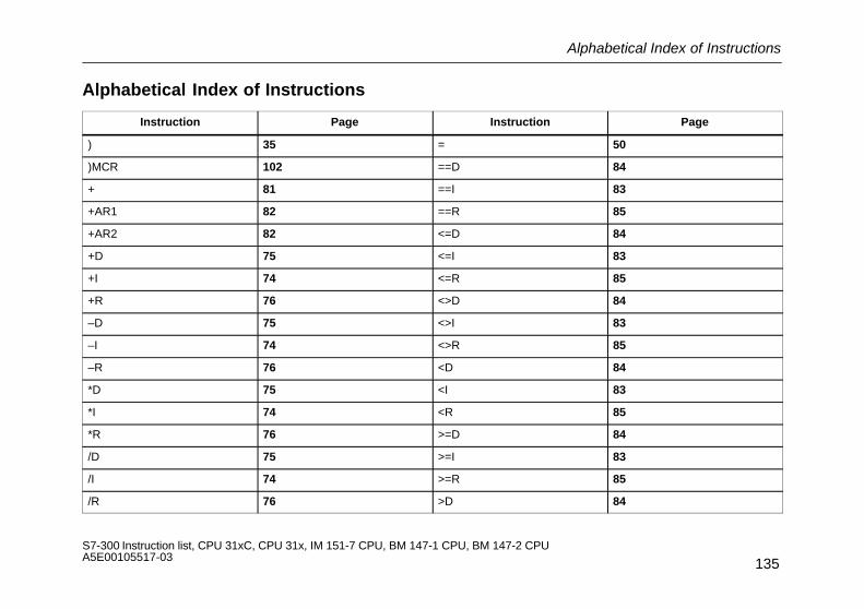
Alphabetical Index of Instructions
135S7-300 Instruction list, CPU 31xC, CPU 31x, IM 151-7 CPU, BM 147-1 CPU, BM 147-2 CPU A5E00105517-03
Alphabetical Index of Instructions
Instruction Page Instruction Page
) 35 = 50
)MCR 102 ==D 84
+ 81 ==I 83
+AR1 82 ==R 85
+AR2 82 <=D 84
+D 75 <=I 83
+I 74 <=R 85
+R 76 <>D 84
–D 75 <>I 83
–I 74 <>R 85
–R 76 <D 84
*D 75 <I 83
*I 74 <R 85
*R 76 >=D 84
/D 75 >=I 83
/I 74 >=R 85
/R 76 >D 84

Alphabetical Index of Instructions
136S7-300 Instruction list, CPU 31xC, CPU 31x, IM 151-7 CPU, BM 147-1 CPU, BM 147-2 CPU A5E00105517-03
Instruction Page Instruction Page
>I 83 CAD 89
>R 85 CALL 94
A 28, 37, 43 CAW 89
A( 34 CC 95
ABS 77 CD 55
ACOS 80 CDB 97
AD 41 CLR 51, 52
AN 29, 38, 44 COS 80
AN( 34 CU 55
ASIN 80 DEC 89
ATAN 80 DTB 91
AW 41 DTR 91
BE 96 ENT 89
BEC 96 EXP 79
BEU 96 FN 46
BLD 90 FP 45
BTD 91 FR 54, 56
BTI 91 INC 89
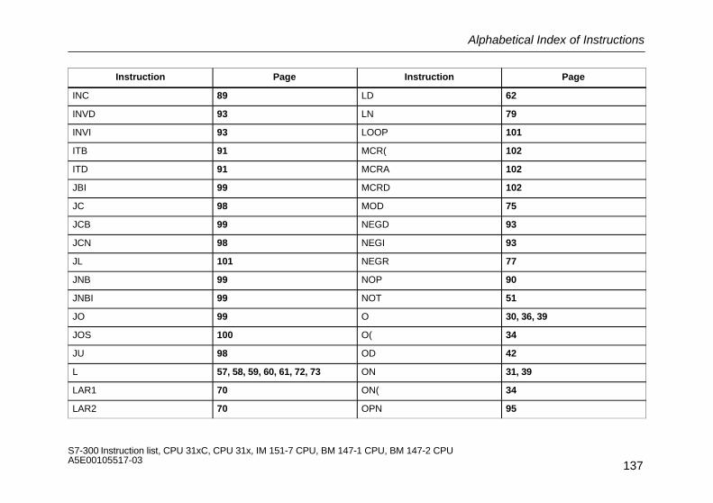
Alphabetical Index of Instructions
137S7-300 Instruction list, CPU 31xC, CPU 31x, IM 151-7 CPU, BM 147-1 CPU, BM 147-2 CPU A5E00105517-03
Instruction Page Instruction Page
INC 89 LD 62
INVD 93 LN 79
INVI 93 LOOP 101
ITB 91 MCR( 102
ITD 91 MCRA 102
JBI 99 MCRD 102
JC 98 MOD 75
JCB 99 NEGD 93
JCN 98 NEGI 93
JL 101 NEGR 77
JNB 99 NOP 90
JNBI 99 NOT 51
JO 99 O 30, 36, 39
JOS 100 O( 34
JU 98 OD 42
L 57, 58, 59, 60, 61, 72, 73 ON 31, 39
LAR1 70 ON( 34
LAR2 70 OPN 95
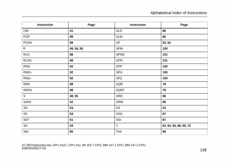
Alphabetical Index of Instructions
138S7-300 Instruction list, CPU 31xC, CPU 31x, IM 151-7 CPU, BM 147-1 CPU, BM 147-2 CPU A5E00105517-03
Instruction Page Instruction Page
OW 41 SLD 86
POP 89 SLW 86
PUSH 89 SP 53, 62
R 49, 54, 55 SPM 100
RLD 88 SPMZ 101
RLDA 88 SPN 101
RND 92 SPP 100
RND+ 92 SPU 100
RND– 92 SPZ 100
RRD 88 SQR 78
RRDA 88 SQRT 78
S 48, 55 SRD 86
SAVE 52 SRW 86
SD 53 SS 53
SE 53 SSD 87
SET 51 SSI 87
SA 54 T 63, 64, 65, 68, 69, 72
SIN 80 TAK 89

Alphabetical Index of Instructions
139S7-300 Instruction list, CPU 31xC, CPU 31x, IM 151-7 CPU, BM 147-1 CPU, BM 147-2 CPU A5E00105517-03
Instruction Page Instruction Page
TAN 80 X 32, 39
TAR 71 X( 34
TAR1 71 XN 33, 40
TAR2 71 XN( 34
TRUNC 92 XOD 42
UC 95 XOW 41

Alphabetical Index of Instructions
140S7-300 Instruction list, CPU 31xC, CPU 31x, IM 151-7 CPU, BM 147-1 CPU, BM 147-2 CPU A5E00105517-03
Recommended