University of PennsylvaniaScholarlyCommons
Theses (Historic Preservation) Graduate Program in Historic Preservation
2011
Corrosion Prevention in Historic Concrete –Monitoring the Richards Medical LaboratoriesAna Paula A. GonçalvesUniversity of Pennsylvania
Follow this and additional works at: http://repository.upenn.edu/hp_theses
Part of the Historic Preservation and Conservation Commons
Suggested Citation:Gonçalves, Ana Paula A. (2011). Corrosion Prevention in Historic Concrete – Monitoring the Richards Medical Laboratories. (Masters Thesis). University ofPennsylvania, Philadelphia, PA.
This paper is posted at ScholarlyCommons. http://repository.upenn.edu/hp_theses/172For more information, please contact [email protected].
Gonçalves, Ana Paula A., "Corrosion Prevention in Historic Concrete – Monitoring the Richards Medical Laboratories" (2011). Theses(Historic Preservation). 172.http://repository.upenn.edu/hp_theses/172

Corrosion Prevention in Historic Concrete – Monitoring the RichardsMedical Laboratories
AbstractThis thesis proposes to analyze current non-destructive techniques for the early detection of factors leading toreinforcement corrosion as part of a preventive conservation strategy for reinforced concrete. Thesetechniques were theoretically evaluated for their efficiency and compatibility of use on concrete surfaces thatrequire a minimum intervention approach, such as found on historic Modernist buildings where exposedconcrete is considered an integral part of their significance. This study considered a real case scenario; theAlfred Newton Richards Medical Research Laboratories (Louis I. Kahn, 1960). The corrosion mechanismoccurring on this building was assessed to assert its probable causes and the most appropriate method ofinvestigation.
DisciplinesHistoric Preservation and Conservation
CommentsSuggested Citation:Gonçalves, Ana Paula A. (2011). Corrosion Prevention in Historic Concrete – Monitoring the Richards MedicalLaboratories. (Masters Thesis). University of Pennsylvania, Philadelphia, PA.
This thesis or dissertation is available at ScholarlyCommons: http://repository.upenn.edu/hp_theses/172
CORROSION PREVENTION IN HISTORIC CONCRETE –MONITORING THE RICHARDS MEDICAL LABORATORIES
Ana Paula Arato Gonçalves
A THESISIn
Historic Preservation
Presented to the Faculties of the University of Pennsylvania inPartial Fulfillment of the Requirements of the Degree of
MASTER OF SCIENCE IN HISTORIC PRESERVATION2011
_______________________________AdvisorMichael C. Henry, PE, AIAAdjunct Professor of Architecture
_______________________________Program ChairRandall F. MasonAssociate Professor

ii
To my mother (in memoriam) who always supported my love of art,
and to my father who has always supported me no matter what.

iii
Acknowledgements
First I would like to thank my advisor, Michael C. Henry, PE, AIA, for his guidance
and support throughout the process of writing this thesis and for pushing me until the very end.
I would also like to extend my gratitude to Randy F. Mason, Frank Matero, and all the faculty of
the Graduate Program in Historic Preservation with whom I learned so much in the past two
years.
Special thanks are due to my wonderful classmates, especially the conservation
science group. Thank you for keeping me company in many sleepless nights during finals, and
for sharing my worries and anxieties. But, above all, thank you for your friendship. I could never
have done this without it.
I thank my father for all his counsels and for taking interest in a diagnostic
process that does not involve an ailing human being. I also thank my sister for being an example
of hard working professional and dedication. I would also like to thank my grandparents for their
support and example.
Finally, I would like to thank God for blessing me with the opportunity of
working in the conservation of historic buildings.

iv
Table of Contents
Chapter 1 Introduction 1Chapter 2 Literature Review 7
2.1. Modern Movement Preservation 72.2. Preventive Conservation 122.3. Early Detection of Reinforcement Corrosion 14
Chapter 3 Corrosion Damage Mechanism in Reinforced Concrete 163.1. Necessary and Sufficient Factors 173.2. Influencing Factors and Possible Causes 203.3. The Three Phases of the Corrosion Damage Process 253.4. Intervention and Prevention 27
Chapter 4 Techniques for Early Detection of Reinforcement Corrosion fora Preventive Conservation Strategy
34
4.1. Measurable Risk Factors for a Preventive Strategy 354.2. Techniques for Early Detection of Reinforcement Corrosion:Description and Evaluation
38
4.3. Survey Strategies for Preventive Conservation of ReinforcementCorrosion
62
Chapter 5 Case Study: Richards Medical Research Laboratories 775.1. Statement of Significance 775.2. History 825.3. Background 87
5.3.1. Location and Climate 875.3.2. Structure and Materials 88
5.4. Current Conditions 925.5. Analyses and Hypotheses 965.6. Proposed Validation Methodology 995.7. Proposed Method for Analysis and Interpretation of Data 104
Chapter 6 Conclusions 127
Bibliography 130Index 135

v
List of Figures
Figure 3.1 Photomicrographs of the interfacial transition zone. (Nemati andMonteiro, 1997)
32
Figure 3.2 Phenolphthalein test showing carbonation front (the non tinted area)advancing from the fracture face of a crack.
32
Figure 3.3 Photomicrographs of corrosion on concrete reinforcement at differentstages of development. (Yuan, Jiang and Peng, 2010)
33
Figure 3.4 Preparation of damaged area to be repaired by patching. (Macdonald,2003)
33
Figure 4.1 Thin section of a concrete specimen analyzed under a petrographicmicroscope. (Walker, Lane and Stutzman, 2006)
69
Figure 4.2 Example of a core sample showing corroded reinforcement andcracks. (Walker, Lane and Stutzman, 2006)
69
Figure 4.3 Schematic of an Initial Surface Absorption Test (ISAT). (Long,Henderson and Montgomery, 2001)
70
Figure 4.4 Schematic of an AUTOCLAM test. (Long, Henderson and Montgomery,2001)
70
Figure 4.5 Schematic of a Figg water penetration test. (Long, Henderson andMontgomery, 2001)
71
Figure 4.6 Schematic of a Schönlin air permeability test. (Long, Henderson andMontgomery, 2001)
71
Figure 4.7 Schematic of a rapid chloride diffusion test. (Long, Henderson andMontgomery, 2001)
72
Figure 4.8 Schematic of an in situ chloride diffusion test (PERMIT). (Long,Henderson and Montgomery, 2001)
72
Figure 4.9 Phenolphthalein tints areas with pH >9. 73Figure 4.10 Alternative pH indicators: tropaeolin O (pH>12.1); mixture of
thymolphthalein and phenolphthalein (pH>11.2). (Yu, Lee and Chung,2010)
73
Figure 4.11 Data acquisition with a handheld GPR antenna.(http://www.geophysical.com/structurescanoptical.htm)
74
Figure 4.12 Schematic representation of a half cell potential measurement set up.(Gu and Beaudoin, 1998)
74
Figure 4.13 Example of equipment that uses a half cell to measure corrosionpotential. (http://www.ndtjames.com/Cormap II 8482 s/100.htm)
75
Figure 4.14 Equipment and procedure used to measure concrete resistivity.(Broomfield, 2007)
75
Figure 4.15 Schematic of linear polarization equipment. (Song and Saraswathy,2007)
76

vi
Figure 5.1 The Richards Medical Laboratories and its relationship with thetraditional 19th century campus architecture.
107
Figure 5.2 Hill Hall (Eero Saarinen, 1960). 107Figure 5.3 David Goddard Laboratories (Louis I. Kahn, 1964). 108Figure 5.4 Florence and David Kaplan Memorial Wing (Louis I. Kahn,
1960;Vreeland and Schlesinger, 1964)108
Figure 5.5 Aerial view showing location of the Richards Medical ResearchLaboratories. (Google Earth, 2010,*annotations added)
109
Figure 5.6 Connection to the John Morgan Building (Cope & Stewardson, 1904)seen from the service driveway.
109
Figure 5.7 Quadrangle (Cope & Stewardson, 1895). 110Figure 5.8 James J. Kaskey Memorial Garden. 110Figure 5.9 First floor plan showing the Richards Medical Research Laboratories
(in green) and the Goddard Laboratories. (Komendant, 1975,*annotations added)
111
Figure 5.10 Enclosed bridge between towers B and X. 111Figure 5.11 Construction photograph showing tower X’s cast in place structure.
(The Architectural Archive, University of Pennsylvania,030.IV.A.490.12.51)
112
Figure 5.12 Ventilation stacks on the south façade of tower X. (Komendant, 1975) 112Figure 5.13 Construction photograph showing the cast in place structure of a
subsidiary tower and the precast structure of a laboratory tower. (TheArchitectural Archive, University of Pennsylvania, 030.IV.A.490.12.42)
113
Figure 5.14 North façade of towers A and B soon after completion. (TheArchitectural Archive, University of Pennsylvania, 030.IV.A.490.7.1)
113
Figure 5.15 Column tendons being connected during erection of the precaststructure. (The Architectural Archive, University of Pennsylvania,030.IV.A.490.11.1)
114
Figure 5.16 Tensioning process in a Vierendeel beam. (Komendant, 1975) 114Figure 5.17 Pile of columns on construction site waiting to be erected. (The
Architectural Archive, University of Pennsylvania, 030.IV.A.490.9.2)115
Figure 5.18 Detail of connection between two column sections and a beam. 115Figure 5.19 Model of the precast structure showing different types of connection.
(Komendant, 1975)116
Figure 5.20 Detail of corner window and brick masonry wall. 117Figure 5.21 Column in situation less exposed to environment action. 117Figure 5.22 Detail of soiled surface. 118Figure 5.23 Corrosion stain associated with spall. 118Figure 5.24 Corrosion stain associated with exposed reinforcement. 119Figure 5.25 Cracks that can develop into spalls. 119Figure 5.26 Longitudinal crack. 120Figure 5.27 Crazing. 120Figure 5.28 Spall on a column flange. 121Figure 5.29 Spall on a window corner. 121Figure 5.30 Exposed reinforcement, originally lacking concrete cover. 122Figure 5.31 Exposed reinforcement on edge beam. 122

vii
Figure 5.32 Repair on the edge of column flange. 123Figure 5.33 Patches on the ground floor level section of the northwest column on
the north façade of tower.123
Figure 5.34 Glossy areas. 124

viii
List of Tables
Table 4.1 ASTM criteria for corrosion of steel in concrete for different standardreference electrodes. (Broomfield, 2007, p.49)
55
Table 4.2 Correlation between potential range and concrete conditions,according to RILEM TC 154 EMC. (Elsener, 2003, p.464)
57
Table 4.3 Correlation between corrosion current measured with devices that usea sensor controlled guard ring and corrosion rate. (Broomfield, 2007,p.75)
61
Table 4.4 Comparison of evaluation techniques. 66

ix
List of Illustrations
Illustration 3.1 Diagram of the three phases of the corrosion mechanism inreinforced concrete and a holistic view of factors that can affectcorrosion.
31
Illustration 5.1 Diagram of the hypothesis of the corrosion mechanism at thepost tensioned precast reinforced concrete in the RichardsMedical Laboratories.
125
Illustration 5.2 Section of precast column showing how the geometry increasesthe surface area making the flanges particularly sensitive to theenvironment. (The Architectural Archives, University ofPennsylvania, 030.I.C.490.009, *annotations added)
126

1
Chapter 1 Introduction
This thesis proposes to analyze current non destructive techniques for the early
detection of factors leading to reinforcement corrosion as part of a preventive conservation
strategy for reinforced concrete. These techniques were theoretically evaluated for their
efficiency and compatibility of use on concrete surfaces that require a minimum intervention
approach, such as found on historic Modernist buildings where exposed concrete is considered
an integral part of their significance. This study considered a real case scenario; the Alfred
Newton Richards Medical Research Laboratories (Louis I. Kahn, 1960). The corrosion mechanism
occurring on this building was assessed to assert its probable causes and the most appropriate
method of investigation.
Research for this thesis involved gathering background information that
provided a sound base of knowledge for its development. The literature review in Chapter 2
summarizes what has been done in terms of preservation of modern architecture, preventive
conservation and developing of non destructive techniques for evaluating corrosion in
reinforced concrete.
This thesis is set on the movement toward the preservation of monuments from
the recent past that has taken place in the past twenty years. The architecture produced
between the 1920s and 1970s had the Modern Movement as its backbone and included all of its
regional manifestations. The initiative to preserve buildings and structures that represent this
historic period sprung from the architecture community’s realization that some of the
masterpieces of the period were under threat. Buildings from this period were (and still are)
suffering from the threat of neglect or demolition, because the ever accelerating rate of change

2
in society’s needs, especially regarding new comfort and technological standards, rendered
them obsolete. However, unlike previous historic periods, the mid 20th century lacks the rarity
and nostalgic values that often engage people’s support in heritage preservation. Furthermore,
the preservation community suddenly found itself faced with the challenge of conserving
materials they had never dealt with and projects that seemed to defy the current preservation
principles. In this respect there has been a long discussion by preservation professionals on the
challenges of preserving both fabric and design intent, which is further explored in Chapter 2.
This thesis also recognizes that it is impossible to dissociate the development of
the Modern Movement from the technological advancements in the construction industry of its
time. The importance of preserving original materials in Modern Movement heritage is based on
this interrelationship. Each branch of the Modern Movement had its own meaning, local
significance and spectrum of influence, but they all shared the characteristic of expressing the
final embrace of industrialization. This was evident in the collaboration between architects and
the construction industry to create new building techniques and materials. Architects and
engineers of the period also recognized the new plastic and aesthetic opportunities generated
by these innovative building methods.1 This resulted in buildings and structures that broke away
from the traditional building morphology to explore the aesthetic use of structural elements.
These elements assumed new forms and their constituent materials were left exposed.
Therefore, not only is the image of the Modern Movement associated with the color and texture
of these construction materials but also most of these buildings would not have been possible
without these new developments.
1 Addis and Bussell, In: Macdonald, 2003, p.43.

3
From all construction techniques, reinforced concrete was the most used in this
period. The focus of this thesis derives from corrosion being the most common damage
mechanism in reinforced concrete. Corrosion’s necessary factors (iron, oxygen and water) are
ordinarily present in a concrete structure. However, this electrochemical reaction becomes
passive in alkaline environments such as fresh concrete. Depassivation occurs when concrete
carbonates or if there is chloride contamination around the reinforcement. On the first stage,
there are no signs of damage on the surface, but, once there is enough accumulation of
oxidation products, the volumetric increase will exert sufficient pressure to rupture the
concrete. At this point, damage is finally observable on the surface and will quickly develop into
a spall, which can only be remediated by removing the affected areas and by patching. It is
important to acknowledge that other damage mechanisms present in the structure can
contribute to the factors leading to the initiation of reinforcement corrosion. This deterioration
process and its phases are described in detail on Chapter 3, where the data from an
investigation aimed at providing comprehensive understanding of concrete characteristics and
the corrosion process that takes place in the reinforcement was gathered.
This thesis was developed on the premise that the current state of technological
development presents no alternatives to the traditional repair methodology. Traditional
patching repair is still necessary when action is taken only after damage is detected on the
surface. This results in further loss of the original concrete compromising the historical and
aesthetical values inherent in it. This is why a preventive conservation approach is the most
adequate for exposed architectural reinforced concrete. It relies on the early detection of the
problem and monitoring of its development, so that intervention can take place while the
process is still in its initial steps. The goal is to slow the deterioration rate by focusing action on
4
the causes of the problem. If damage is already present, this approach can make repairs more
effective by identifying the damaged areas more precisely and acting on the factors that could
lead to re initiation of the deterioration process. A preventive strategy must be based on a
comprehensive understanding of the deterioration, its causes and the risk factors present in the
building. Therefore surveying historic reinforced concrete buildings to locate and identify these
factors is an essential step in implementing a preventive strategy.
However, the present conservation literature contains little on the subject of
survey techniques for early detection of corrosion in reinforced concrete. This thesis was
developed as an attempt to bridge this gap. Research involved recent articles that analyzed
techniques that could be useful in answering the questions raised by hypothesis developed in
the diagnosis of corrosion damage mechanisms in reinforced concrete structures. This research
was conducted in professional and scientific publications on material science, non destructive
evaluation techniques, concrete and electrochemistry. Preference was given, when possible, to
techniques classified as non destructive and that can be performed in situ. Emphasis was given
to providing information on the type of data acquired from each technique, their limitations,
and possible adverse effects to the concrete surface. The intention was to inform conservators
on the possibilities of these techniques so that when faced with a reinforced concrete structure
they will know the appropriate course of action and which specialists to consult. The data
gathered in this phase along with an analysis of how these techniques can be combined in order
to provide a complete picture of the damage mechanism can be found in Chapter 4.
A preliminary assessment of the conditions found on post tensioned precast
reinforced concrete elements on the façade of the Richards Medical Research Laboratories at

5
the University of Pennsylvania provided a practical case study for this thesis. This case study was
selected in order to keep this thesis close to the requirements of practice, while still keeping it
broad enough to be applied in other cases. This particular building was chosen because of its
well established historical significance and relationship to its concrete structure. In addition, the
building has been showing clear signs of reinforcement corrosion on its façades, which had not
been diagnosed yet. An analysis of the post tensioning tendons in the structural elements at the
Richards Medical Laboratories was not part of the scope of this thesis due to the specificity of
the evaluation techniques that such an analysis would require. Another factor for the election of
the Richards Medical Laboratories as a case study was the availability of original documentation
at the Architectural Archives and the Facilities and Real Estate Department Archives, both at the
University of Pennsylvania.
This methodology was based on the scientific approach to diagnosis proposed
by Watt.2 Therefore, it started with data gathering on the building, which included retrieval of
historic and archival data on the building’s construction, and in situ observations. Based on this,
hypotheses were developed to explain the cause of the damages observed. This analysis
revealed a complex relationship between different conditions found in the structure. These new
factors prompted a broader investigation of the deterioration mechanisms that affect reinforced
concrete. The goal was to determine how they altered the characteristics of the material that
resulted in higher susceptibility to reinforcement corrosion. These hypotheses generated
questions that need to be answered in order to validate the hypotheses. The knowledge
gathered in this thesis’ first phase of investigation informed the proposal of an evaluation plan
for the Richards Medical Laboratories that intends to confirm the hypothesis formulated. This
2 Watt, 2007, p.166.
6
was included in Chapter 5 along with a compilation of all data found on the state of the Richards
Medical Laboratories, a description of the conditions observed there and the hypothesis
formulated to explain them.
This thesis demonstrates that prevention is the best approach for the
preservation of historic reinforced concrete structures, especially when exposed architectural
reinforced concrete is involved. A preventive strategy must be based on sound knowledge of the
building and diagnosis of the damage mechanisms afflicting it. In the case of buildings with
reinforced concrete this requires the use of techniques that are capable of detecting
reinforcement corrosion before it has affected the concrete. Therefore, the preservation of
monuments from the mid 20th century will depend on conservators getting acquainted with the
possibilities and limitations of concrete survey techniques. This thesis is an introduction to this
field and an invitation to further research on this subject.
The conservation of reinforced concrete is still in its infancy, if compared to the
conservation of other building materials such as stone and brick masonry. However, the
quantity of potentially historic buildings that use reinforced concrete and their rapid decay rate
urges further investigation in this field.

7
Chapter 2 Literature Review
This chapter provides a context for the development of this thesis. The current
state of discussions on the subject of Modern Movement preservation provides the theoretical
background that supports the need for the development of preventive conservation strategies
for reinforced concrete. Preventive conservation has mainly been discussed in relation to the
Modern Movement preservation in terms of the importance of implementing cyclic
maintenance programs and the need for further development of appropriate techniques for in
depth investigation of deterioration causes. The concept of preventive conservation is
presented in order to establish the differences between what is currently considered a
preventive conservation approach and what would be necessary to implement this same
philosophy in a reinforced concrete building. This chapter also includes an overview of the
current state of technological development in non destructive techniques for reinforced
concrete.
2.1. Modern Movement Preservation
During the last decade of the 20th century and into the 21st, there has been an
upsurge in publications concerning the preservation of recent heritage including principles,
methodology and techniques. The two most prolific organizations represented in this body of
publications are English Heritage (the agency that counsels the English government on heritage
preservation issues) and DOCOMOMO (an international non profit organization that advocates
the preservation of Modern Movement architecture). Both organizations have responded to the
recognition that the legacy of the most recent historic period is threatened by a lack of
8
knowledge among experts on how to deal with the new challenges imposed by mid 20th century
architecture.1,2
Authors such as Susan Macdonald,3,4 John Allan,5 Peter Burman6 and Theodore
Prudon7 are in agreement that the main challenge that distinguishes the preservation of 20th
century architecture from the preservation of more traditional buildings is the difficulty in
reaching a balance between design intent and material authenticity. The difficulty lies on the
multiple factors that influence this negotiation.
The first factor is the historic proximity to the moment of the conceptualization
of the design, which does not grant the time needed for the accumulation of other significant
historic layers. Therefore, there is a natural tendency to place more value on the original design
and appearance of the building than on the patina of age or later modifications. This argument
is often used to justify large scale replacement of original material that has failed to perform as
expected, with similar materials that perform better, but maintain the design intent intact.
The second factor is the scale of material failure encountered in 20th century
architecture. Buildings of this period often use materials and details that had not passed the test
of time and durability that has benefitted traditional building techniques such as carpentry,
where current practices have been developed over many centuries of trial and error. As a result,
buildings of the recent past frequently present early failures, where preservation or “in kind”
1 Guillet, In: Macdonald, Normadin and Kindred, 2007, p.151 156.2 Macdonald, In: Stratton, 1997, p.207 224.3 Ibid.4 Macdonald, 2001, p.32 40.5 Allan, In: Macdonald, Normadin and Kindred, 2007, p.13 46.6 Burman, In: Stratton, 1997, p.15 33.7 Prudon, 2008, p.25.

9
replacement of the original fabric might lead to continuing decay of the building.
Standardization being a goal of the construction industry throughout the 20th century, an
unsuccessful design or construction detail might compose a large portion of the building,
resulting in compromise of material authenticity if replaced. An aggravating factor to be
considered: the innovative use of building material, even if unsuccessful, is sometimes an
important aspect of the building’s significance.8 Large scale material failure in 20th century
buildings is also related to the mid century optimism in the indestructibility of new building
materials. This optimism was used to justify the general lack of maintenance in these buildings,
but it also gave basis for the use of building materials in exposed locations as the aesthetic of
choice.9 The lack of protective cladding makes these structures more vulnerable to weathering
and decay, since there is no sacrificial layer to protect them. In addition, the modern aesthetic
advocated for the elimination of all façade details which were decorative, but also served as
protection from weathering by shedding water away from the building.10 In the case of
reinforced architectural concrete, the monolithic nature of the material adds to the difficulty of
incremental or spot repairs.11 As a result, the overall material homogeneity of the surface is
easily ruined by a poorly executed patch.
According to Peter Ross, the early failure of concrete in post war buildings is
related to the false belief that concrete was a durable material, combined with a change in
concrete manufacture in the 50s.12 The spike on the building industry, thanks to post war
rebuilding efforts, caused a competition among cement manufacturers for the production of a
8 An interesting example of this paradox is the replacement of original prefabricated reinforced concretepanels at Auguste Perret’s Notre Dame du Raincy, 1923. (Macdonald, 1996, p. 91)9 Starting with Le Corbusier in the 20s and culminating with Brutalism on the post war era.10 Matthews, et al., In: Macdonald, 2003, p.196.11 Ross, In: Stratton, 1997, p.143.12 Ibid., p.155.

10
product that would gain strength more quickly in the curing process. The result was cement with
finer grains and concrete mixes with lower cement content, resulting in cured concrete of
increased porosity and lower durability (this relationship shall be further explained on the
subsequent chapter).
The third contributing factor identified by the authors was the lack of
appropriate repair techniques for 20th century materials. The current practices in concrete
repair, for instance, are contrary to the conventional preservation principles of minimum loss of
material fabric and maximum addition to the lifespan of the structure.13 The current repair
methods can be divided in two categories, patches and coatings. Patch repair requires the
removal of original damaged fabric, which is difficult to match in both color and texture, and
weathers at a different rate, and it does not solve the origin of the damage. On the other hand,
coatings offer protection from external factors that might trigger deterioration but they often
alter the original appearance of the building and introduce extra maintenance costs.
The surveyed publications presented the challenge but also proposed solutions.
On the matter of principles there was a reaffirmation of the validity of the methodology
presented by the Burra Charter.14 This charter advocates that all intervention should respect the
values that contribute to the cultural significance of the structure and that these values change
over time.15 As time passes, a reassessment of the building’s significance will allow the addition
13 “With traditional buildings such as stone or timber we have established, over the past 100 years ormore, repair methods which enable the maximum amount of building fabric to be retained, whilstextending the life of that building. When we are dealing with twentieth century architecture built ofmaterials such as concrete we have not yet established methods which fulfill such aims (…)” Macdonald,In: Stratton, 1997, p.210.14 Burman, In: Stratton, 1997, p.31 3215 Australia ICOMOS, 1999.

11
of new layers of history.16 This methodology allows design intent and original appearance of
Modern monuments to be granted a higher degree of importance, but recognizes that the
hierarchy of values should be reviewed in the future as the building continues to be a part of
history. The publications on the preservation of Modern architecture also recognized that, like
the heritage of any other period, the material fabric, as the vehicle through which significance is
conveyed, should be preserved as much as possible. Therefore, new conservation techniques
needed to be developed. There was also an appeal for the development of more accurate
diagnostics of damage mechanisms and the incorporation of maintenance programs as a
preventive measure following a repair campaign.17 The publications focused on the study of
non destructive repair techniques, such as electrochemical methods to arrest further
development of reinforcement corrosion. However, few of them mention any survey techniques
and none of them offers a critical analysis of the techniques for early detection for preventive
conservation, presumably because the publications were a response to historic buildings where
immediate action was needed.
Terry S. Kreilick’s master thesis in Historic Preservation at the University of
Pennsylvania was one of the few works in the field of architectural conservation that presented
a general description of different survey methodologies. Although the focus of the thesis was
electrochemical repair methods, a chapter was dedicated to a very brief description of
techniques that could be used to assess the reinforcement corrosion at Frank Lloyd Wright’s
Freeman House. It included corrosion potential measurement, corrosion rate measurement,
16 Prudon, 2008, p.21.17 Macdonald, 2001, p.32 40.

12
concrete cover measurement, electrical continuity of reinforcement, chloride concentration,
carbonation depth and petrographic analysis. 18
The only publication directed at conservation professionals and completely
dedicated to concrete deterioration was edited by Susan Macdonald in 2003. This book compiles
papers developed by different authors covering all aspects of concrete conservation. John
Broomfield, a renowned British corrosion specialist, contributed to this publication with a
chapter on the identification of deterioration mechanisms in concrete, which includes a section
on condition survey techniques. He briefly describes each one of them and stresses that a
survey will most likely require multiple techniques. He also wrote the chapter on repair
techniques with Susan Macdonald.
2.2. Preventive Conservation
According to Alice Finke, preventive conservation is a philosophy that has the
goal of maximizing the life span of a historic resource by taking action to minimize probable
deterioration risk factors.19 In other words, it directs action toward the causes and not the
consequences of the deterioration mechanism. Finke’s research revealed that this is still a new
and relatively unknown concept in architectural conservation, although it is well established in
object conservation. Her case studies showed that preventive architectural conservation is
usually done through regular examinations that include monitoring for risk factors and frequent
visual inspections.
18 Kreilick, 2000, p.55.19 Finke, 2008, p.10 11.
13
The preventive conservation approach starts with a comprehensive study of the
structure at hand in order to understand all possible threats and which factors might trigger
damage mechanisms.20 Documentary research of all prior repair and alteration campaigns is
essential, as well as a scientific characterization of the materials that compose the building. In
addition, an initial visual assessment of the entire building should be conducted to locate
possible ongoing problems and risks. With some training a surveyor will be able to identify most
decay mechanisms early enough for the intervention to be minimal, therefore preserving more
of the original fabric.
However, the limitations of visual detection are where preventive conservation
of reinforced concrete diverges from that of other building materials. The most common
damage mechanism found in reinforced concrete is reinforcement corrosion. The damage
caused by corrosion initiates inside the concrete element and usually remains hidden until it has
developed enough to cause damage to the surface of the concrete in the form of cracks and
spalls (this mechanism will be explained in detail on the subsequent chapter). The problem is
that when reinforcement corrosion affects the concrete surrounding it, the only possible
remedy is traditional repair, which involves further loss of original fabric. Although current
patching techniques are not much different than what was done twenty years ago, matching
color and texture has become more common. The question that remains is whether these
patches will age similarly to the original material. As mentioned before this kind of repair also
triggers discussions on authenticity. In conclusion, visual inspections and material
characterization are important tools for preventive conservation, but they are not enough when
the material surveyed is reinforced concrete. In such cases, the inspection should be
20 Ibid., p.8.

14
complemented with non destructive techniques that can provide some insight on the
reinforcement condition under an apparently healthy concrete cover.
2.3. Early Detection of Reinforcement Corrosion
Non destructive testing for concrete structures began to be developed in the
1970s, but gained momentum in the subsequent decades.21 This upsurge of interest is
connected to the need to lower maintenance costs in reinforced concrete infrastructure,
especially bridges, and the recent concern with environmental sustainability which encourages
decreasing the amount of raw material consumption by repair instead of replacement.22
Corrosion being the principal cause of deterioration of reinforced concrete bridges, many
techniques have recently been developed to detect insipient corrosion or its consequences such
as delaminations. Most of these techniques involve electrochemical, electromagnetic or acoustic
wave methods. It is important to remember that these techniques have been classified as “non
destructive” by engineering and materials professionals concerned with minimizing repair costs
in civil infrastructure. Therefore, “non destructive” is associated with techniques that cause
minimal damage, but these techniques are not necessarily harmless to the surface of the
building from the perspective of the architectural conservator.
It usually takes a long time for a new testing technique to emerge from of Non
Destructive Testing research and become accepted as a standard of care in the practice of civil
engineering.23 It is only after this process of acceptance that architectural conservators start to
get in contact with non destructive techniques by the engineers who specialize in structural
21 Song and Saraswathy, 2007.22 Mancio, Zhang and Monteiro, 2004.23 McCann and Forde, 2001, p.71.

15
assessment of historic buildings. Techniques that have become common practice in the building
industry are easily recognized by the existence of consensus standards compiled by industry
associations such as ASTM (American Society for Testing and Materials), ACI (American Concrete
Institute) and RILEM (Reunion Internationale des Laboratoires et Experts des Materiaux,
Systèmes de Construction et Ouvrages).
The most recent scientific developments have been directed at improving the
accuracy of well accepted techniques such as potential mapping, corrosion rate measurement
and ground penetrating radar. These new developments concentrate on the improvement of
data collection and processing, and imaging for interpretation, while still using the same
technology for the data acquisition. Their goal is to increase accuracy in order to minimize the
repair area, which would reduce the project’s costs, but also preserve more original fabric.

16
Chapter 3 – Corrosion Damage Mechanism in Reinforced Concrete
In order to prevent reinforcement corrosion, or at least slowing its process, it is
essential to have a comprehensive knowledge of how the corrosion mechanism develops and
the factors that initiate and affect its progression. In order to facilitate comprehension, these
factors have been broken down in four categories according to their relationship to the
corrosion mechanism. Harris defines necessary factors as the ones that must be present in order
for the mechanism to exist, in other words, the subtraction of any of them would render the
mechanism impossible.1 The same author also defines sufficient factors as those capable of
initiating the mechanism. Influencing factors are those that indirectly result in reinforcement
corrosion, because they determine the development of one or more necessary and sufficient
factors. Possible causes are the primary conditions that can lead to influencing or even
necessary factors (ill. 3.1). Recognizing the different factors that can contribute to corrosion,
directly or indirectly, is important in order to understand how the corrosion mechanism relates
to different environmental and material characteristics.
In addition to understanding its initiation process, it is also important to
understand how the corrosion process progresses. This process is marked by key thresholds that
divide the process into distinct phases (ill. 3.1). When considering intervention, the chosen
approach should be tailored to the specific corrosion phase, since each phase presents different
types of damage. This will dictate the scale of the intervention as well as the extent to which an
intervention would be invasive to the existing material, an important consideration with historic
buildings. Based on this comprehensive understanding of the damage process, it is possible to
1 Harris, 2001, p.22.

17
define strategies for the early detection of corrosion as part of a preventive conservation
approach (Chapter 4).
3.1. Necessary and Sufficient Factors
Corrosion of steel is a naturally occurring electrochemical process where the
unstable metal iron (Fe) reacts in the presence of oxygen (O2) and water (H2O) to produce a
more stable molecule, hydrated ferric oxide (Fe2O3.H2O), also known as rust. This process is
initiated when an iron atom releases electrons in order to become an ion (Fe2+) – an anodic
reaction. These electrons are consumed in a reaction with water and oxygen generating
hydroxyl ions (OH ) – a cathodic reaction. This cycle of releasing and consuming electrons form
an electric current, similar to what happens in a battery. The presence of an aqueous solution is
important, since an electrolyte will generate an environment with low electric resistivity,
allowing an easy circulation of electrons. The ions generated on both reactions will form ferrous
hydroxide (Fe(OH)2), which will further react with water and oxygen becoming ferric oxide
(Fe(OH)3). Finally, the ferric oxide, being an unstable molecule, becomes hydrated ferric oxide.2
2 According to Broomfield (2007, p.7 8) the formation of rust can also be expressed in other ways.
Corrosion’s Chemical Reactions:(Broomfield, 2007, p.7 8)
Fe Fe2++ 2e
½ O2+ H2O+ 2e 2OH
Fe2++ 2OH Fe(OH)2
4 Fe(OH)2+ O2+ 2H2O 4 Fe(OH)3
2 Fe(OH)3 Fe2O3.H2O + 2H2O

18
Any reinforced concrete structure exposed to the atmosphere, without
protective coating or cladding, presents the necessary elements for these reactions to occur.
Iron from the reinforcement steel3 can be exposed to oxygen and water entrapped during the
mix and later, water penetrating from the atmosphere via interconnecting pores in the
concrete. However, the highly alkaline environment provided by concrete (pH 12 13) renders
iron oxides (corrosion products) thermodynamically stable due to the creation of an anodic
polarization4 on the steel surface.5 These stable molecules are less prone to chemical
dissolution, thereby creating a densely packed protective layer of iron oxides that isolates the
sound steel core from the corrosive environment.6,7 This layer is known as the passive layer. The
nature, composition and structure of passive layers in metals have been studied for the past 150
years, but a consensus has not yet been reached.8
The origin of concrete alkalinity lies on the calcium hydroxide (Ca(OH)2) that
comprises 20 25 percent of the volume of solids in the hydrated cement paste.9 As long as the
pH of the concrete surrounding the reinforcement is maintained above 11.5, the passive layer
will remain stable.10,11 Breaking the passivity of the corrosion reaction in the reinforcement steel
is a sufficient factor for corrosion. This passivity can be broken in two cases: carbonation or
chloride contamination of the concrete. Carbonation is the reaction between calcium hydroxide
3 Unless the rebar is epoxy coated or made of stainless steel. These are very recent technologicaladvancements that will only appear in mid century buildings if used in a recent repair campaign.4 Anodic polarization refers to a situation where a material looses electrons to its environment, creating apositive potential. (Schennach, 2006/2007, p.2)5 Schennach, 2006/2007, p.12.6 Glass and Buenfeld, In: Macdonald, 1996, p.105.7 MacDougall and Graham, In: Marcus, 2002, p.190.8 Ibid.,p.189.9 Mehta and Monteiro, 2006, p.29.10 Ibid., 2006, p.179.11 Broomfield, 2007, p.17.

19
and carbon dioxide (CO2) that results in the formation of calcium carbonate (CaCO3) in the
concrete mass. This causes the pH to drop to 8.12 This process occurs as carbon dioxide from the
atmosphere progresses towards the reinforcement through the surrounding concrete.
Carbonation initiates as soon as the structure is built, but it is usually a slow process that
depends on the permeability of the concrete and the atmospheric concentration of carbon
dioxide. In order to keep the carbonation front from reaching the reinforcement during the
structure’s design service life, the reinforcement should be provided with an appropriate
concrete cover thickness.13
Chloride contamination initiates reinforcement corrosion differently from
carbonation. Chloride ions are capable of breaking the passive layer without lowering the pH of
the concrete and without being consumed in the process. The exact process, whereby chloride
breaks the passive layer, is not known.14 Passivity is broken when the chloride concentration
surpasses 0.6 of the hydroxyl concentration in the concrete.15 Chloride ions can result from
contact with de icing salts16 or from the atmosphere if the building is located in a salt water
environment. Until the mid 1970s, it was common to use calcium chloride as an additive to
12 Broomfield, 2007, p.18.13 Cover thickness is kept to the minimum necessary, because minimizing the amount of material isusually prioritized in order to lower construction costs.14 McDougall and Graham, In: Marcus, 2002, p.204.15 According to Broomfield (2007, p.23), this ratio is approximately 0.4% chloride by weight of cement ifchlorides are cast into concrete and 0.2% if they diffuse in.16 Both of the most common types contain chloride: sodium chloride (NaCl) and calcium chloride (CaCl2).
Carbonation’s Chemical Reactions:(Broomfield, 2007, p.16)
CO2+ H2O H2CO3
H2CO3+ Ca(OH)2 CaCO3+2H2O

20
accelerate concrete curing,17 therefore the concrete mix of buildings from this period can also
be an inherent source of chloride.
In short, corrosion will happen when the reinforcement is in contact with
oxygen and water. Most important, it will become a damage mechanism in reinforced concrete
if the pH of the concrete encasing the reinforcement drops below 11.5 or if the concrete
presents enough chloride concentration to break the passive layer.
3.2. Influencing Factors and Possible Causes
Concrete permeability and the thickness of the concrete cover on the
reinforcement are the most important factors influencing the corrosion process and its rate.
Concrete permeability controls the access of corrosion inducing factors to the reinforcement,
such as oxygen, water, chlorides, and carbon dioxide that causes carbonation. Permeability also
determines the electric resistivity of concrete, because the electric currents will be subjected to
the tortuosity of the paths provided by water in the pore network. Concrete cover thickness is
also important in creating a barrier for corrosion agents, but its main role is to provide enough
distance between the reinforcement and the carbonation front. Both of these influencing
factors can be affected by multiple conditions.
Concrete cover thickness is determined by the engineer’s specifications before
construction. Even when the specifications are correct, there is still the possibility of error
during construction. The occurrence of errors such as misplacement when a worker places the
reinforcement in the wrong position , or displacement when an initially correct placement is
disturbed of the reinforcement on the formwork happen more often in environments with low
17 Broomfield, 2007, p.20.
21
quality control and oversight, such as found on construction sites in the case of a cast in place
structure, but it can also happen in precast plants. This kind of error might also be caused by the
incompatibility between a complex design and the available level of skill and experience of the
workers, this situation affects both precast and cast in place reinforced concrete structures.
These two causes for lack of concrete covering, design and construction, are easily
distinguishable on buildings, since construction errors would show as random areas with less
covering than others, and an inadequate design would result in uniform lack of cover.
Permeability refers to the capacity of a material to allow liquid or gas to pass
through it. This characteristic is determined by the amount of voids, their size and connectivity
that form a network throughout the material. The volume of capillary voids in concrete depends
mainly on the water/cement ratio of the mix.18 Voids are formed during hydration when space
that was initially occupied by water is not filled with solid hydration products. Consequently, the
more water in the mix, the more space is left unfilled. However, not all pores contribute to
permeability, in concrete, only pores larger than 100 nm form interconnected voids, the smaller
ones tend to remain isolated.19 The key factor in defining the permeability of concrete is the
microstructure of the interface zone between the hydrated cement paste and large aggregates.
The existence of the interfacial transition zone, usually 10 to 50 μm thick around large
aggregates,20 is the reason why concrete has a higher permeability than cement paste with the
same water/cement ratio (fig.3.1). This happens because larger aggregates attract water during
curing increasing the water/cement ratio on its surroundings. The result is the formation of
larger crystals and a greater quantity of calcium hydroxide (needlelike crystals oriented toward
18 Mehta and Monteiro, 2006, p.36.19 Ibid., p.41.20 Ibid., p.24.

22
the aggregate) composing a porous framework.21 Although this condition might improve with
age due to the late formation of hydration products, the microstructure of the interfacial
transition zone remains more porous than the hydrated cement paste. This poor microstructure
and higher porosity negatively affects the strength of the concrete in general. Moreover, it
creates zones of weakness that are more prone to microcracking, which increases the
permeability even more. Pores present in aggregates also influence the total permeability of
concrete, this will depend on the physical characteristics of the stone used.
Both micro and macro cracks play an important role in the penetration of liquid
and gases in concrete by providing continuous and easier paths through it. Cracks also increase
the surface area exposed to the atmosphere, thereby expanding the carbonation front and the
area contributing to moisture absorption (fig.3.2). Therefore, even when shallow cracks are
restricted to the concrete surface they contribute to concrete deterioration. Cracks can be
caused by many different mechanisms that damage the concrete by exerting internal pressures
higher than the concrete’s tensile strength. Most of these mechanisms relate to how the
concrete reacts to its environment which is mainly determined by its composition,
microstructure that results from it, and form.
Mechanisms that cause concrete cracking:
a) Drying shrinkage: strain caused by the loss of adsorbed water from calcium
silicate hydrate (C S H) due to exposure of concrete to an unsaturated environment. The use of
good quality aggregate that, in the drying process, shrinks less than the concrete paste restrains
concrete shrinkage and avoids cracks. The effect of aggregates depends on the volume used in
21 Mehta and Monteiro, 2006, p.43.

23
the concrete mix, as well as the aggregates’ modulus of elasticity. Curing conditions influence
this phenomenon. Environmental conditions during curing, such as the ambient temperature,
relative humidity and wind speed, can increase the drying rate and cause cracks due to drying
shrinkage. Other factors that increase drying rate include the precipitate removal of formwork
and geometry of element (a high perimeter/section ratio increase the rate of moisture loss).22
b) Crazing: a form of drying shrinkage that shows as discontinuous hairline
cracks that occur on the surface of freshly hardened concrete and are caused by a higher water
concentration on the element’s surface due to improper curing and finishing. Common in
exposed concrete with a smooth finish (low concentration of aggregates close to the surface).23
c) Creep: strain that is also caused by the loss of adsorbed water from calcium
silicate hydrate (C S H), but for a different reason than drying shrinkage. In this case, cracking is
caused by the long term action of stress that causes water loss. Influenced by the same factors
as drying shrinkage.24
d) Stress in compression: a loaded structure can develop cracks even if the
ultimate strength has not been reached. According to Mehta and Monteiro, a stable microcrack
system develops in the interfacial transition zone under 50% of the ultimate stress, some of
which were initiated before loading due to thermal and drying shrinkage. When a concrete
structure is subjected to 50 75% of the ultimate stress the crack system becomes unstable and
proliferates through the cement matrix. Any stress above that will cause a rapid propagation of
cracks and eventually result in failure.25 This situation can be aggravated if a structure is loaded
before it has reached the required initial strength. For example, a structural member that is
22Mehta and Monteiro, 2006, p.95.23 Ibid., p.380.24 Ibid., p.95.25 Ibid., p.89.

24
post tensioned before it reaches the minimal strength for this procedure, or a precast piece
that, prior to attaining sufficient strength, is loaded during shipping, handling or erection
procedures.
e) Stress in tension: concrete is not usually used in tension due to its brittle
nature, which is why concrete elements subjected to any kind of tension are reinforced with
steel. Structural elements in tension, such as beams, have a higher concentration of
microcracking on the tensioned zones. Poupard, et al., described a case where corrosion rate
was higher on the bottom of a beam (the tensile zone), which was attributed to the higher
permeability caused by microcracking.26 However, concrete can also be exposed to this kind of
stress in unique situations such as improper handling and transportation of pre cast elements,
failure of reinforcement or earthquakes.
f) Thermal expansion/contraction: caused by the concrete’s response to the
changes in temperature and aggravated by the poor distribution or lack of expansion joints.
g) Freeze/thaw: formation of ice lenses inside the concrete pores during curing
under freezing temperatures, if the structure is not properly protected. The volume increase
caused by freezing water can exert enough pressure on the surrounding material to rupture it.
The level of damage depends on the amount of cycles of freeze and thaw that the pore water
goes through, therefore the local climate must be characterized by temperature fluctuations
that repeatedly go above and below freezing. The microstructure of the material is the
determining factor for the damage caused by this mechanism, because having voids that can
accommodate the ice growth can prevent the pressures it causes.
26 Poupard, et al., 2006, p.518.

25
h) Alkali silica reaction: chemical reaction between the alkali content of
concrete and unstable silica minerals27 that results in the formation of gels that expand in the
presence of water. Depends on the mineral composition of aggregates and exposure to water.
i) Sulfate attack: chemical reaction between the alumina containing hydration
products, calcium hydroxide (also a hydration product) and sulfate ions resulting in the
formation of ettringite, which causes expansion. Sulfate can be found in aggregates that contain
gypsum, atmospheric pollution, industrial and natural water.
j) Reinforcement corrosion: the corrosion products have a much bigger
volume than the original steel, this causes internal pressures in the concrete (this phenomenon
will be further explained on the next section).
It is interesting to observe that all mechanisms that depend on the ingress of
water or a contaminant are influenced by the concrete permeability. Once they cause enough
pressure to crack the concrete, they end up increasing their own rate of damage due to the
creation of more efficient pathways for moisture transport via the crack network, essentially
bypassing the low permeable mass of concrete. This makes the reinforced concrete more
susceptible to the initial deterioration mechanism, but also to the initiation of other
mechanisms that are governed by the penetration of water and other atmospheric components,
such as reinforcement corrosion.
3.3. The Three Phases of the Corrosion Damage Process
As previously mentioned, the corrosion process in concrete reinforcement can
be divided in three distinct phases that take place once concrete is no longer a passivity inducing
27Alkali reactive minerals: opal, obsidian, cristobalite, tridymite, chalcedony, chert, andesite, rhyolite andmetamorphic quartz (Mehta and Monteiro, 2006, p.170).

26
environment (ill.3.1). The first phase is characterized by the accumulation of corrosion products
on the interface between the reinforcement and the concrete. Hydrated iron oxides have a
volume six to ten times bigger than that of the original iron.28 This expansion will at first be
accommodated by voids in the concrete mass surrounding the reinforcement.29 However, once
these spaces are occupied, the volume increase, constrained by the lack of available space,
builds up pressure and causes tensile stress on the surrounding concrete (fig.3.3). Once this
pressure surpasses the tensile strength of concrete, cracks start to appear. This marks the
transition of the process to another phase where corrosion is not only attacking the
reinforcement, but is also damaging the concrete mass by creating new fractures or enlarging
existing cracks.
This phase is characterized by an acceleration of the damage rate due to an
increase in water and oxygen penetration resulting from the new or enlarged cracks.30 Not only
does the volume of water penetrating the concrete mass increases, but the rate of wetting and
drying cycles increases as well. The increased frequency of wetting phases supply more water to
the corrosion process, while the increased frequency of drying phases allow more space for
oxygen penetration. Further accumulation of corrosion products widens and multiplies the
cracks. These appear as parallel cracks on the concrete surface aligned with the longitudinal
direction of the corroding reinforcement bar. In a cross section, these cracks clearly radiate from
the reinforcement bar. As time passes, the progressive enlargement of the cracks and the
weathering of the internal surfaces of the cracks can lead to loss of key in the fracture face and
28 Broomfield, 2007, p.9.29 Yuan, Jiang and Peng, Nov Dec 2010, p.565.30Ibid., p.564.

27
develop into a spall. This phenomenon characterizes the transition to the final phase in the
corrosion process.
This last phase is marked by loss of concrete surface mass due to spalls, which
result in direct exposure of the corroding reinforcement to the atmosphere and reduction of the
concrete cover over adjacent reinforcement. Once exposed to the atmosphere, the
reinforcement has no protection against the necessary factors for corrosion. Consequently, the
process will progress until all iron has oxidized. Since iron oxides are not structurally sound, the
progressive loss of steel section will eventually threaten the stability of the structure due to the
transfer of tensile strain from the steel to the surrounding concrete, which is by then
compromised by fracturing and weathering.
3.4. Intervention and Prevention
The degree and kind of damage caused by each phase will guide the appropriate
intervention approach. It is important to highlight that while there is little accumulation of iron
oxides on the steel concrete interface, deterioration develops under the concrete surface,
hidden from sight. In addition, damage to the concrete progresses rapidly once cracks become
evident on the surface. From that moment on, intervention is likely to include patching, and the
resultant fabric loss is inevitable in this repair process.31 Grouting is not recommended when
cracks have been caused by reinforcement corrosion, unless grouting is used as a temporary
stabilization until the appropriate repair can be made. Grouting should only be regarded as
provisional, since it might diminish the rate of corrosion by blocking the by pass access to water
and oxygen provided by the cracks, but it does not address the cause of damage which is
31Broomfield and Macdonald, In: Macdonald, 2003, p.165.

28
reinforcement corrosion. Corrosion will continue to occur, consequently, soon causing further
cracks in the concrete. There is also the question of proper adhesion, since the presence of
loose corrosion products might compromise the contact between grout and concrete.
Traditional patching is used because it has the capacity of reestablishing
passivity locally and arresting the corrosion mechanism. This process consist of removing the
affected areas of concrete with enough depth to completely expose the reinforcement (fig.3.4),
which is then cleaned or replaced as appropriate and the area is refilled with new concrete,
thereby re passivating the corrosion reaction. This new concrete will have to be matched both
in color and texture to the original surface, which can be challenging and is rarely done
satisfactorily. One of the reasons is that the concrete used for patching has to reach a
determined strength and be able to bond to the substrate, these characteristics usually
determine the proportion of the mix, the additives, and the type of binder used. However, the
proportion and type of materials used in the mix can significantly affect the final color, which is
likely to be different from the original concrete. Pigments can be used to help reaching the
appropriate color, but they tend to age differently from the original fabric, mainly due to
pigment fading. According to Broomfield and Macdonald, the patch can be matched to the
original appearance of the concrete and look different from the rest of the structure until it
acquires a similar patina. A common practice is to apply an opaque coating on the whole surface
to hide the patches, this not only erases the patina but also softens the surface texture. In cases
where the patch was matched to the aged concrete, it started to become distinct from the rest
of the surface with further weathering.32 Another point to be considered is that patches will not
necessarily work structurally. Consequently, patching can affect structural stability if performed
32 Broomfield and Macdonald, In: Macdonald, 2003, p.165.

29
in a large scale without the appropriate structural appraisal by an experienced engineer. The
patch has to extend beyond the location of observable damage and substitute the entire
carbonated or chloride contaminated area in order to be effective. Alternatively, the patch can
be restricted to the damaged area if combined with other techniques that address the cause of
the corrosion, such as impressed current cathodic protection, electrochemical chloride
extraction and realkalisation.
These electrochemical techniques depend on a current source that is connected
both to the reinforcement and an external anode. Among electrochemical approaches, the
impressed current cathodic protection technique is the only permanent installation. Impressed
current cathodic protection uses a low current to invert the electrochemical reaction so that the
reinforcement that has been acting as an anode becomes a cathode. As long as the system is
properly functioning the reinforcement will no longer corrode, instead, this oxidizing reaction
will take place in the external anode, which will need replacing after 10 40 years depending on
its composition.33 The anodes have to be uniformly distributed across the surface, so proper
planning is essential in order to minimize impact to a historic building’s appearance.
Electrochemical chloride extraction is a temporary installation. Treatment can
take about eight weeks to be completed. Differently from cathodic protection, this technique
uses high current to drive chloride ions outside of the concrete. Electrochemical chloride
extraction is capable of removing between 50 90% of the chloride content.34
33 Broomfield and Macdonald, In: Macdonald, 2003, p.173.34 Ibid., p.176.

30
Realkalization is also a temporary installation, but the process is faster than
chloride removal. Realkalization uses a low current and a carbonate electrolyte to increase
alkalinity in carbonated concrete.
These electrochemical repair techniques share the same restrictions. According
to Broomfield and Macdonald, they are difficult to apply in prestressed concrete members and,
since they require electrical connection to the reinforcement, they can be expensive in
structures where the reinforcement is not continuous, such as precast structures. Although they
generally require a higher initial investment than traditional repairs, they tend to be cost
effective on the long term, because of the savings with future repairs.
It should be remembered that the loss of original fabric is an undesirable
outcome when the building or structure in question has historical value. Loss of original fabric
poses a threat to the aesthetic quality of the exposed concrete, as well as to the historic
integrity of the building. However, the options of noninvasive treatments are still quite limited
for reinforced concrete. Therefore the most appropriate approach would be to act preventively,
before the concrete is irreversibly affected by the corrosion process.

31
CORROSION CRACK SPALL
pressure > concrete’s tensile strength
crack widening and erosion of internal surfaces
DRYING SHRINKAGE
CONCRETE PERMEABILITY CONCRETE COVER
CONCRETE MIX:• adi ves• water/cement• aggregates
REINFORCEMENT PLACEMENT & CONCRETE POURING
DESIGN
Possible Causes
CRACKS
ALKALI-SILICA REACTION
FREEZE/THAW
TENSIONCOMPRESSION
CREEP
TIME
CARBONATIONCHLORIDESWATER
Su cient FactorsNecessary Factors
IRON(regular reinforcement steel)
+
1st phase 2nd phase 3rd phase
OXYGEN
In uencing Factors
CURING
CRAZING
THERMAL EXPANSION/CONTRACTION
SULFATE ATTACK
LOAD
WATER
TEMPERATURE
Illustra on 3.1- Diagram of the three phases of the corrosion mechanism in reinforced concrete and a holis c view of factors that can a ect corrosion.

Figure 3.1- Photomicrographs of the interfacial transi on zone. (Nema and Monteiro, 1997)
Figure 3.2- Phenolphthalein test showing carbona on front (the non- nted area) advancing from the fracture face of a crack.
32

Figure 3.3- Photomicrographs of corrosion on concrete reinforcement at di er-ent stages of development. (Yuan, Jiang and Peng, 2010)
Figure 3.4- Prepara on of damaged area to be repaired by patching. (Macdon-ald, 2003)
33

34
Chapter 4 –Techniques for Early Detection of Reinforcement Corrosion for a
Preventive Conservation Strategy
Preventive conservation, in the case of reinforcement corrosion, refers to any
actions targeting factors that contribute to the corrosion process with the goal of delaying its
initiation or slowing the rate of damage that it might cause. Therefore it is appropriate to say
that the preventive approach should be employed before corrosion has caused cracks in the
concrete. The preventive opportunity occurs before the corrosion products have reached a
volume sufficient to rupture the concrete, and after a repair campaign, when the corrosion
process is returned to its incipient stage. The preventive approach is based on the
acknowledgement that all exposed concrete structures in contact with the atmosphere and built
with common steel reinforcement have the necessary factors for corrosion to occur.
Preventive strategies have to be founded on a sound knowledge of the building.
Therefore the first measure is to gather detailed and comprehensive information on the
building’s history, previous repair campaigns and material characteristics. This should be
followed by an investigation on the possible presence of sufficient factors, such as carbonation
and chloride contamination. Whether or not they are present, an assessment of which risk
factors might lead to the development of sufficient factors is also necessary. Two kinds of
actions are possible, either conducted individually or in combination: monitoring the progress of
sufficient and risk factors, and taking measures to stop their development by acting on the
primary conditions described on the previous chapter.

35
The present chapter first describes the risk factors that can be assessed, and in
which phase of the process this should be done as part of a preventive strategy for
reinforcement corrosion. Later, this chapter describes and evaluates the techniques that are
currently employed in the early detection of risk factors and corrosion in reinforced concrete.
The chapter concludes with general strategies on how to compose a survey plan that can serve
as a base for the development of a preventive approach to conservation, and according to each
structure’s specificities.
4.1. Measurable Risk Factors for a Preventive Strategy
The previous chapter identified the necessary factors for corrosion water,
oxygen, and iron and the sufficient factors for corrosion initiation in reinforced concrete –
carbonation of concrete surrounding the reinforcement or enough concentration of chloride
ions to cause depassivation. Based on this, a list of risk factors can be compiled as part of an
assessment of their presence and evolution in the building as the first step in a preventive
strategy. Since preventive strategies are only appropriate when implemented before the
corrosion mechanism has caused mechanical damage to the concrete, the time frame of action
is restricted to before initiation of corrosion, and to the first phase of the damage process once
corrosion has started.
Factors acting in this time frame can be divided between constant and
progressive. The first term refers to factors that are inherent characteristics to the structure and
do not evolve with time. The second term refers to factors, inherent or not, that pose no initial
threat, but that can evolve into one due to aggravating mechanisms. The assessment method
for these factors should reflect their nature, because while constant factors may be measured

36
only once during the life time of the building, progressive factors should be measured every
time a new assessment is conducted. Moreover, in the case of progressive factors, the rate of
their evolution will have a bigger impact on the building’s life span than their immediate
measured value.
Two factors can be classified as constant:
a) Depth of cover mostly a function of design and workmanship,
therefore unlikely to change over time. The measurement of cover depth and reinforcement
location can produce drawings equivalent to architectural as built plans. Depth of cover could
be considered a progressive risk factor if the structure is exposed to a highly abrasive
environment, such as water tides.
b) Chlorides in the concrete mix – calcium chloride used to be added to the
concrete mix in order to accelerate the curing process until the mid 1970s. In this case, the
residual chloride concentration could be sufficient to break corrosion passivity right after
concrete curing.
The progressive factors category holds the remaining risk factors:
a) Liquid and gas penetration – considered the most influential risk factor,
because it controls the access of external agents that constitute necessary and sufficient factors,
such as water and oxygen, or that inflict depassivation, like carbonation and chloride
contamination. Liquid and gas penetration through concrete is a consequence of concrete
permeability and crack formation that provides easier paths to liquid and gas transport.
Permeability decreases in time due to carbonation, but the quantity of cracks tends to increase
in time with the progress of deterioration mechanisms causing them. Though initial permeability

37
can be sufficient to allow the ingress of a deleterious amount of external agents, as in the case
of a low strength concrete (high water/cement ratio), liquid and gas penetration can be
progressively aggravated due to the bypass effect of cracks.
b) Carbonation – as previously explained, the progressive transformation
of calcium oxide into calcium carbonate in the presence of carbon dioxide takes place in every
exposed concrete structure, however the concrete characteristics (low permeability and high
cement content) can maintain a slow rate in the carbonation front progress, so that carbonation
will not reach the reinforcement during the projected life span of the structure. The challenge
with structures that have become historic or architecturally significant is that they are expected
to last much longer than expected when they were initially designed. Therefore an estimation of
the carbonation front’s rate of progress is important in predicting when the protective highly
alkaline environment surrounding the reinforcement will be lost.
c) Chloride ingress – the availability of chloride sources where the
structure is located will determine if this is a risk factor to be considered. The most common
external sources are sea water spray that is carried by the wind in marine environments and de
icing salts in climates susceptible to freezing temperatures. Chloride ions are not consumed in a
chemical reaction, so their concentration is always increasing as long as the source remains.
Since the presence of chlorides can break the passive layer once chloride concentration reaches
a certain threshold, monitoring chloride concentration and its rate of change is useful in
estimating the time remaining before depassivation.
Once corrosion has started, measuring the parameters mentioned above will be
useful in determining causality. In addition, identification of the areas where reinforcement is
corroding along with an estimation of corrosion rate is important in guiding the planning phase

38
of an intervention. Together, these measurements can produce information that can be used to
minimize the area of intervention through increased accuracy in defining damage location,
maximize the durability of the intervention by guiding it to act on the primary causes of the
damage, and prevent the development of mechanical damage to the concrete by indicating the
presence of active corrosion underneath the surface of sound concrete.
4.2. Techniques for Early Detection of Reinforcement Corrosion: Description and
Evaluation
The techniques described herein are well known in the concrete industry.
However, some, especially non destructive techniques (NDT) for corrosion detection, have not
yet found their way into common building conservation practice. This section describes
techniques that can be used in the early detection of reinforcement corrosion and risk factors,
and evaluates these methods in the context of historic preservation and building conservation.
Therefore they will be analyzed according to their effectiveness and compatibility with sound
historic preservation principles, such as minimum intervention (see table 4.4 in the end of the
chapter).
In the case of tests that require sampling of the concrete, this should be done
according to ASTM C823 “Standard Practice for Examination and Sampling of Hardened
Concrete in Constructions”. This standard recommends that a sampling plan should be made
according to the type of data that needs to be extracted from the material. For example, if the
goal is to identify the origin of an observable problem, samples should be taken from both
deteriorated and sound areas made of the same concrete mix. Results will be derived from the
comparison between these samples. On the other hand, when the goal of the test is to

39
determine average and distribution of properties, samples should be taken from randomly
chosen areas if the concrete is consistent throughout the building. However, if it is clear that
different areas present different concrete mixes, sampling of each concrete type should be
proportional to its occurrence.1
The number of samples should be determined statistically according to ASTM
E122 “Practice for Calculating Sample Size to Estimate with a Specified Tolerable Error the
Average for Characteristic of a Lot or Process”.2 However, this is not usually possible since the
number of samples can be high enough that the cost of the sampling process could be
prohibitive. In historic buildings, the number of samples is further restricted by the significance
of the material. The appropriate number of samples depends on the mean and standard
deviation values calculated from the results gathered from each sample. Therefore, the
appropriate sample size can only be calculated after a preliminary sampling is done. This often
results in extra sampling being needed. Friedman proposes alternatives to minimize the
possibility of errors without sampling more. A conservative intervention plan could be used to
counteract the possibility of false negatives by accepting a large number of false positives.
Asking for a second opinion from an experienced professional and comparing the case at hand
to other similar cases can orient the decision making process. This kind of practice can force a
positive result despite of a negative result. Another option proposed by Friedman is to
complement the results of a destructive test with data obtained by less invasive or non
1 Poole, 2006, p.20.2 Steele, 2006, p.22.

40
destructive tests. However, he alerts that accurate sampling size is still the most reliable method
of obtaining results, especially when dealing with an unusual case.3
a) Context and historic research
Any survey technique must be informed by documentary research into the
history and context of the building, especially when the building is historically significant.4,5 It
can reveal some of the risk factors that can lead to reinforcement corrosion and give focus to
subsequent investigations. A study of the building’s context should include a characterization of
the local climate and air pollutants. This will give an idea of what types of deterioration agents,
such as sulfates, might be penetrating the concrete. In addition, context research will inform
whether winter temperatures justify the use of de icing salts, if the atmosphere can contribute
to increase the concrete’s moisture content, or if warm temperatures might accelerate
corrosion. This study should also include a description of the structure’s location and
surroundings. For example, the building’s closeness to a salt water source could implicate in
increasing chloride content over time. In addition, different deterioration levels between
façades could be explained by the surrounding buildings that could influence the degree of
exposure of the building’s façades to rain and wind. It is also important to understand the state
of knowledge available at the time and place of construction on the material and construction
technique employed.
Historic research should be conducted using both primary and secondary
sources. Construction drawings, specification documents and photographs taken during
3 Friedman, 2000, p.44.4 ASCE SEI, 2000, p.3.5 Venice Charter, article 9.

41
construction can aid in understanding how the building was constructed, as well as the
composition of the materials. It should be noted that information derived from design
documents should be regarded as guidelines for further investigation, since later modifications
to the design, materials and construction might not be documented. Other important sources
of information are accounts of previous repairs and old conditions assessment reports. They can
determine if a deterioration mechanism reoccurs throughout the structure’s life, or whether a
mechanism that is no longer present could have influenced the current condition.
b) Visual inspection
Visual inspection is the second step of the survey phase. Combined with the
background research mentioned before, it will guide the detailed investigation that will follow.
Although this can be considered the most simple of all survey techniques, visual inspection relies
on the surveyor’s skills of observation, training and experience.6 The safety and comfort of the
surveyor also play an important role in the accuracy of the results when the access to the
structure is challenging. The level of access by the surveyor to the deteriorated areas
determines different degrees of accuracy and detail.7 Therefore the method of access should be
compatible to the purpose of the survey. In the case of large structures, the complexity and
costs of vertical access restricts initial inspection to what can be seen from the ground,
sometimes aided by binoculars or camera lenses. Alternatively, a representative area of the
building could be surveyed. As a consequence, if an intervention is programmed, time should be
reserved to re inspect the structure once scaffolding has been installed, and budget should be
set aside for the likely readjustments that will follow.
6 Watt, 2007, p.151.7 Prudon, 2008, p.176.

42
Any visual assessment requires the compilation of a glossary with the types of
conditions to be noted and recorded, preparation of a set of drawings and rectified photographs
that can be used to map conditions. An annotation system that meets the needs of the survey
project should be developed on a case by case basis, since the number and nature of conditions
can vary. This information can be directly plotted on digital format with the use of portable
digital tablets, or later transferred to a computer. Recently, software has been developed to
facilitate field data collections. Mapping systems such as GIS (Geographic Information System)
have become the most popular. Advantages include the quantification and spatial identification
of damage areas, and tools that aid in the correlation analysis of various conditions and their
possible sufficient factors and risks.
c) Petrographic analysis
Petrographic analysis is not a single test, but a whole area of expertise that is
based on the field of geology. This technique obtains data through macroscopic and microscopic
observations of samples. Depending on what is being investigated and the method of
observation, samples can be cut in cross section and polished, or in thin sections that allow the
use of transmitted light (fig.4.1). Specific characteristics can be enhanced with dyes, acid etching
and spot testing. The results are highly dependent on the experience of the petrographer.
Sampling for petrographic analysis of hardened concrete requires extraction by
core drilling. This sampling technique uses a diamond core drill to extract a cylindrical sample
from the structure, usually 100 mm in diameter and, preferably, 203 mm in depth (fig.4.2). A
minimum of three cores per tested area should be taken. Fragments broken due to
deterioration or extracted with a sledge hammer can be used for a preliminary evaluation, but

43
core samples would still be needed for obtaining a definitive result. When the objective of the
petrographic analysis is to identify cause of deterioration, two separate areas should be sampled
for comparison, an area affected by the deterioration and another area that is not deteriorated,
but that share the same concrete mix.8
Although core sampling can be considered destructive for a historic structure,
the amount and range of information that it can provide through petrography is still unmatched
by any other technique. For example, petrographic examination can provide the proportion of
the different concrete phases, such as coarse aggregate, fine aggregate, voids and cement paste.
The area occupied by macroscopic features can be measured by grid counting on core halves,
while microscopic features can be measured by point counting in thin sections.9 Acid etching is
commonly used to enhance the difference between cement paste and aggregates, because the
cement paste is left on a second plane after being etched away. In a thin section, voids can be
enhanced with dyes and incident fluorescent light under a petrographic microscope. The same
thin section can also be observed with transmitted cross polarized light to identify carbonation
products and alkali silica gel. In addition, petrographic analysis can provide the water/cement
ratio based on paste texture, distribution of non hydrated cement grains, speed of water
absorption and reaction upon scratching. A more specific ratio can be provided by chemical
analysis.10
Petrographic analysis should be done according to the ASTM C457 98 “Standard
Test Method for Microscopical Determination of Parameters of the Air void System in Hardened
8 Walker, Lane and Stutzman, 2006, p.247.9 Broekmans, 2009, p.645.10 Walker, Lane and Stutzman, 2006.

44
Concrete” and ASTM C856 95e1 “Standard Practice for Petrographic Examination of Hardened
Concrete”.
d) Liquid and Gas Penetration test
Liquid and gas penetration tests the volumetric transport of a liquid or a gas
through a material. Transport depends on the volume of pores, their shape and size, and on the
connection between them. There are three types of transport occurring in the material, and
each can be tested separately. Absorption is transport of liquid in a solid by capillary suction,
permeability is the inherent capacity of the material to transport liquid or gas through the
material under pressure, and diffusion is the transport of ions and molecules from an area with
higher concentration to an area with lower concentration.
Based on the fact that moisture is a necessary factor in most damage
mechanisms that attack reinforced concrete, many researchers identify permeability as a
reliable indicator of concrete durability.11 As explained in the previous chapter, the penetration
of liquid and gas can increase due to cracks caused by different types of damage mechanisms,
which increase the rate of deterioration because cracks provide a path of lower resistance to the
ingress of deterioration agents. Therefore, this is a condition that should be monitored over
time. Monitoring requires that a test be performed several times, consequently, minimizing the
damage caused by the test is essential. However, most liquid and gas penetration tests have to
be performed in a laboratory using samples. Thus in situ techniques for measuring this
characteristic will be given priority in this study. The advantage of in situ techniques is that they
11 Long, Henderson and Montgomery, 2001, p.66.

45
have a smaller impact on the original material because they do not require sampling. However,
the results of in situ techniques can be affected by the presence of moisture in the pores.
It is important to notice that both laboratory and in situ tests are referred to as
“permeability” tests in the professional literature, but for the purpose of this thesis the term
“permeability” only refers to the capacity of the concrete to transmit fluid as determined by the
pores in the concrete’s microstructure without transport through micro and macro cracks.
Since so called “permeability” tests actually measure transport without distinction of void type,
these techniques will be referred to as liquid/gas penetration tests in this thesis.
Determining absorption demonstrates how much moisture will penetrate the
concrete when water comes in contact with the surface. It can be tested in a number of ways,
the most simple of which is a standpipe test. This test consists of measuring the volume of
water absorbed through a given surface area over a certain period of time using a graduated
vertical pipe. This device is standardized by RILEM Commission 25 PEM Test n°11.412 and it has
to be tightly attached to the concrete surface with removable putty. Although this test has the
advantage of being harmless to the surface and easy to perform, it is not sensitive enough to
distinguish between different absorption levels in concrete.13 Long, Henderson and Montgomery
describe three other tests that are more sensitive. The Initial Surface Absorption Test (ISAT) uses
a watertight cap connected to a water reservoir and a calibrated capillary tube (fig.4.3). It
measures the time taken by the water level at the capillary tube to change, once a water head
of 200 mm is applied. The main difficulty is to ensure a watertight seal that will not damage or
leave residues on the surface. The AUTOCLAM sorptivity test (fig.4.4) is similar to the ISAT, but it
12 RILEM, 1980, p.175 253.13Ibid, p.71.
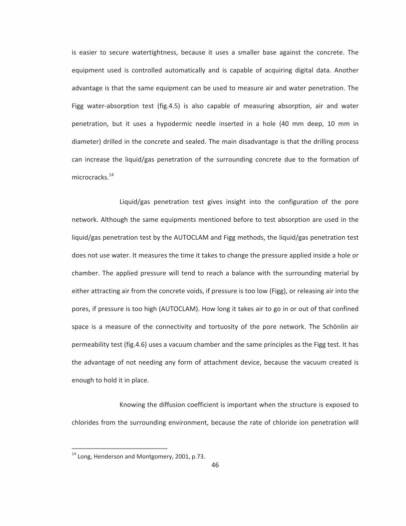
46
is easier to secure watertightness, because it uses a smaller base against the concrete. The
equipment used is controlled automatically and is capable of acquiring digital data. Another
advantage is that the same equipment can be used to measure air and water penetration. The
Figg water absorption test (fig.4.5) is also capable of measuring absorption, air and water
penetration, but it uses a hypodermic needle inserted in a hole (40 mm deep, 10 mm in
diameter) drilled in the concrete and sealed. The main disadvantage is that the drilling process
can increase the liquid/gas penetration of the surrounding concrete due to the formation of
microcracks.14
Liquid/gas penetration test gives insight into the configuration of the pore
network. Although the same equipments mentioned before to test absorption are used in the
liquid/gas penetration test by the AUTOCLAM and Figg methods, the liquid/gas penetration test
does not use water. It measures the time it takes to change the pressure applied inside a hole or
chamber. The applied pressure will tend to reach a balance with the surrounding material by
either attracting air from the concrete voids, if pressure is too low (Figg), or releasing air into the
pores, if pressure is too high (AUTOCLAM). How long it takes air to go in or out of that confined
space is a measure of the connectivity and tortuosity of the pore network. The Schönlin air
permeability test (fig.4.6) uses a vacuum chamber and the same principles as the Figg test. It has
the advantage of not needing any form of attachment device, because the vacuum created is
enough to hold it in place.
Knowing the diffusion coefficient is important when the structure is exposed to
chlorides from the surrounding environment, because the rate of chloride ion penetration will
14 Long, Henderson and Montgomery, 2001, p.73.

47
determine when depassivation will occur. There are different tests that can be done, most of
which are performed in a laboratory using core samples. They basically consist of exposing each
face of the sample to a solution with a different concentration of chlorides and applying an
electrical potential difference to stimulate transport (fig.4.7). ASTM C1202 10 “Standard Test
Method for Electrical Indication of Concrete's Ability to Resist Chloride Ion Penetration” should
be used as guidance.
Recently, there have been some successful attempts at developing an in situ
chloride diffusion test.15 The principles of this test are exactly the same as the process described
above, the difference is in the equipment set up. The in situ ion migration test, known as
PERMIT, uses two cylinders concentrically placed on the concrete surface (fig.4.8). The inner
surface contains a cathode submerged in a chloride solution, and the outer cylinder contains an
anode submerged in distilled water. When the potential difference is applied, chloride ions flow
from the inner ring, through the concrete and into the outer ring. A selective electrode is used
to measure chloride concentration in both solutions until stabilization. The slope, formed before
stabilization is reached, is used to calculate the coefficient of ion migration. Basheer, et al.,
informs that the test area should be pre wetted before measurement. The location of the test
area should take in consideration that reinforcement located within 25 mm of the surface can
affect test results by falsely increasing the concrete resistance to ion migration. Even though
chloride ions inserted in the process can be effectively removed after testing, nitrate ions could
15 Long, Henderson and Montgomery, 2001,p.75.
48
be used alternatively. In addition, the authors conclude that further development is required to
decrease the testing time of ten hours, so that it can be practical for field use.16
e) Phenolphthalein test (carbonation depth)
Phenolphthalein is an organic compound, C20H14O4, which is regularly used to
classify substances as basic or acidic. It has the property of changing color depending on the pH,
colorless if the pH is less than 9 and pink if it is more than 9 (fig.4.9). Phenolphthalein is highly
soluble in ethanol and insoluble in water.17 A solution of phenolphthalein can be used as a
qualitative test to indicate depth of carbonation in concrete elements, it is inexpensive, and it
does not require special training to be performed. According to Broomfield,18 maximum color
contrast can be obtained with a solution of 1g of phenolphthalein in 100ml of a 50:50 alcohol
water mix. This solution should be sprayed on freshly exposed concrete, either by splitting a
core sample or on a fresh fracture on the structure. Therefore, carbonation testing can be
considered a destructive technique, since it inflicts mechanical damage to the built fabric in
order to be performed, and the same area cannot be tested again, because once fracture
exposes a new surface, carbonation will start in this new area. Care should be taken not to cross
contaminate concrete layers with dust from different depths. It is also necessary to pre wet the
surface in case the concrete is very dry.
Although this test is well known and established in practice, there is no
consensus standard to guide its application.19 This might not be relevant for an immediate
evaluation of carbonation depth, but if previous tests have been made, a reliable comparison
16 Basheer, et al., 2005, p.228.17 http://en.wikipedia.org/wiki/Phenolphthalein18 Broomfield, 2007, p.55.19 Yu, Lee and Chung, 2010, p.1.

49
might not be possible if the same procedure is not followed. This can seriously compromise an
estimation of carbonation rate. The reliability of this test is undermined by a variation in
solution concentration utilized, amount sprayed, moisture content of the concrete, surface
condition and time of measurement.20 Sometimes this test can also be affected by aggregate’s
composition and the concrete color can provide poor contrast with the phenolphthalein, making
it difficult to read.
However, the most important consideration regards the pH level at which any
changes can be observed, known as the “end point”. Phenolphthalein stains areas with pH
above 9, but a pH below 11 is sufficient to break corrosion passivity.21 Therefore, if carbonation
is still in an initial stage around the reinforcement this test will not indicate the passivity loss. Yu,
Lee and Chung have researched alternative chemicals that could be used instead of
phenolphthalein or in combination with it. Their goal was to find an indicator whose end point
was equal to or higher than pH 11, with a good hiding power to provide more contrast with the
concrete, low toxicity and market availability. Their results indicate that tropaeolin O and a
mixture of thymolphthalein and phenolphthalein meet these requirements, with end point of
12.1 and 11.2 respectively (fig.4.10). These alternatives also proved to have better color stability
than pure phenolphthalein.22
Once the sample is stained and the carbonation depth is measured, the results
should be plotted against depth of concrete cover. This comparison can indicate areas where
the reinforcement is no longer protected by high alkalinity. An estimation of carbonation rate
can be made by considering that the process has started right after hydration was complete.
20 Ibid., p.2.21 Broomfield, 2007, p.56.22 Yu, Lee and Chung, 2010, 6 7.

50
This should only be considered an estimation, because as carbonation progresses it decreases
the permeability of the concrete cover. The permeability decrease causes the carbonation rate
to drop. A more accurate result could be obtained by comparing carbonation depth values
taken at different times in the structure’s life, but, as stated before, the lack of standardization
can compromise this comparison.
f) Chloride concentration measurement
Chloride ions can damage reinforced concrete if they are present in the pore
solution of the concrete surrounding the reinforcement and once they reach critical
concentration. Broomfield identifies two critical concentration values: 0.4% of Cl by weight of
cement if chlorides are cast into concrete and 0.2% if they diffuse into concrete after it has
cured.23 However, Angst alerts that even after fifty years of research on this subject, no
agreement has been reached among professionals on a value for the critical chloride
concentration threshold.24 Not all chloride ions result in reinforcement corrosion. Inherent
chloride ions that are bound to molecules, either from aggregates or cement paste, are less
important than the free ions diffused in from the atmosphere and found in solution inside
pores.
Current techniques for measuring chloride concentration in concrete have to be
performed in a laboratory with samples extracted from the building. These techniques either
measure total chloride content or free chloride content, depending on the sample preparation
required by each technique. These measurements should be performed on multiple samples,
23 Broomfield, 2007, p.23.24 These authors published a literature review on the subject. They identified the cause of disagreementas being the multitude of factors that influence the chloride threshold and the different techniques usedto measure chloride content in each research. (Angst, et al., 2009, p.1123)

51
extracted from different areas of the structure, to ensure a result that is statistically correct.
Material collected at different depths can also provide a profile of chloride concentration, which
can be analyzed along with the material’s diffusion constant in order to estimate the
penetration rate.25
Total chloride content measurement techniques are performed in samples that
have been powdered and dissolved in nitric acid solution. The amount of dissolution time and
the strength of the solution can affect the quantity of bound chlorides released. The
concentration of Cl ions in the resulting solution can be measured with a variety of techniques
such as titration, ion selective electrodes or spectrometric methods. Angst considers X Ray
Fluorescence Spectrometry the most accurate technique, albeit more expensive. As a
consequence of these techniques being well accepted by professionals, standards were
developed: ASTM C 1152 “Standard Test Method for Acid soluble Chloride in Mortar and
Concrete” and RILEM TC 178 TMC “Testing and Modeling Chloride Penetration in Concrete”.
Free chloride content measurement techniques differ from total chloride
techniques in the sample preparation. For example, high pressure can be used on a sample to
extract its pore water solution. However, this procedure is inadequate for concrete specimens
with low water/cement ratio, coarse aggregate, or very dry samples. Some studies also raised
the concern that the pressure might be high enough to pull away weakly bound chlorides,
increasing the resulting value.26 Another way of extracting the pore water solution is through
leaching. This technique requires grinding the sample and mixing it with a mild solvent, such as
distilled or boiling water, that will not dissolve bound chloride.
25 Broomfield, 2003 (http://www.jpbroomfield.co.uk/html/corrosion_topicscondition_surveys.htm#Chloride)26 Angst, et al., 2009, p.1134.

52
According to Angst, total chloride content measurements are more frequently
used because the effect of bound chloride on reinforcement corrosion is not fully understood
yet, and there is also a question of reliability of the techniques that perform free chloride
measurements.27 Though corrosion risk might be overestimated with total chloride
measurement, it allows for a margin of error that can be useful in the evaluation of such a
complex mechanism of deterioration.
As described above, most of these techniques require extensive sampling and
the consumption of the sampled material during analysis. The procedure has to be repeated
every time a structure exposed to environmental sources of chloride is assessed, which would
pose conflicts with the preservation of historical value of the material. The need for a laboratory
and the time consuming techniques that are currently available have to be taken into
consideration when planning a survey. Some alternative techniques are being studied, such as
laser induced breakdown spectroscopy which has the capacity of quickly determining total
chloride content of a sample without the need of a controlled environment. Though still in its
infancy, this technique has the potential to be developed as an on site assessment tool.28
Another advantage is the small amount of material consumed in the process, which consists of
vaporizing a small amount of surface material using a short laser pulse. Then, the chemical
composition of this material can be determined by analyzing the radiation emitted by using a
spectroscopic technique. Researchers have been working on improving the calibration of the
technique to make chloride readings more evident in the resulting spectrum.29
g) Ground penetrating radar (GPR)
27 Ibid., p.1136.28 Wilsch, et al., 2005, p.724.29 Ibid.

53
This survey technique emits radio pulses and detects their reflections caused by
sharp density changes in the material. At present, it is successfully used to locate voids and
metal in reinforced concrete, as well as measure the concrete cover thickness over the
reinforcement. The equipment is composed of an antenna to emit radio pulses, a transducer to
collect reflected pulses and a portable computer to store the digital data produced. The
equipment can vary in size and frequency. For example, bridge deck surveyors frequently use
GPR equipment that can be attached to a vehicle, but handheld equipment is also available in
the market. Data collection is very fast and it works by creating sections of the surveyed
element as the transducer is dragged along a grid at regular intervals (fig.4.11). This data is
entered into a computer where software creates a graphical representation of void, interface
and reinforcement locations based on the data.
The accuracy of the graphic images depends on precise positioning of measured
sections. Broomfield recommends the use of an electronic distance measuring wheel attached
to the system.30 Another solution, applied by Taffe, Hillemeier and Walther, and Stainbruch, is
the use of an automated survey system coupled to a frame that guarantees the perfect
alignment of the measurements.31,32 Accuracy of the results also depends on the frequency of
the antenna and the concrete conductivity.33 While higher frequencies provide better
resolution, highly conductive concrete decreases resolution due to its attenuation effect on the
propagating waves. However, increasing the frequency has a negative effect on the maximum
depth of readings. Consequently there must be a compromise between required surveyed depth
30 Broomfield, 2007, p.86.31 Taffe, Hillemeier and Walther, 2010, p.6.32 Stainbruch, 2009, p.4.33 Perez Gracia, et al., 2009, p.4.

54
and resolution when choosing the appropriate antenna frequency. Broomfield recommends 1.5
GHz for concrete surveys.34
Recent advancements in digital data processing capacity contributed
significantly to the improvement of GPR data interpretation and accuracy. Stainbruch describes
the advantages of 3D GPR surveys, such as the easier interpretation of results. He also mentions
the possibility of using the technique to characterize the concrete with regards to its porosity,
humidity and chloride content. According to Stainbruch, this was possible due to the increased
sensitivity of the equipment for the detection of weak signals.35
h) Half cell potential mapping
This technique is used to perform a qualitative analysis of reinforcement
corrosion in reinforced concrete. It uses a high impedance digital voltmeter (around 10
megohm)36 to measure the potential difference between a known metal embedded in a pre
fixed solution of its ions (an electrode) and an unknown (fig.4.12). In this case, the unknown is
the steel reinforcement (iron alloy) embedded in a solution of corrosion products (iron oxide) of
unknown concentration. It indicates the probability of corrosion, because it assesses the
presence of dissolved iron ions in the concrete pores surrounding the reinforcement, but not
depassivation. If corrosion is active, there will be a higher concentration of iron ions in the
solution surrounding the reinforcement, thereby generating a lower potential. By convention,
the positive terminal of the voltmeter is connected to the steel and the negative terminal to the
reference electrode, therefore areas with active corrosion will have values that are more
34 Broomfield, 2007, p.86.35 Stainbruch, 2009, p.1.36 Broomfield, 2007, p.46.

55
negative. These values depend on the nature of the metal used as the reference electrode,
consequently results should be compared to threshold values according to the electrode type,
such as the values identified on ASTM C 876 9 “Standard Test Method for Half Cell Potentials of
Uncoated Reinforcing Steel in Concrete” and on RILEM TC 154 EMC “Recommendations: Half
Cell Potential Measurements Potential Mapping on Reinforced Concrete Structures”.37
Half cell potential measurements require a direct electric connection with the
reinforcement, implying a small removal of concrete to uncover the reinforcement (fig.4.13). In
order to minimize fabric loss, areas where the concrete has already spalled or where previous
patch repairs have been made can be used for this connection. Once the steel is exposed, it
should be cleaned and all corrosion removed in order to provide a good electric connection.
Before proceeding with any measurements, the reinforcement should be checked for
discontinuities, this can be done with a DC resistance meter placed between two well separated
points on the reinforcement. According to Broomfield, the resistance should be less than 1
ohm.38 Once the reinforcement and the reference electrode are connected to the voltmeter, the
reference electrode is placed on the concrete’s surface taking point measurements on a pre
37 Elsener, et al., 2003.38 Broomfield, 2007, p.48.
Copper/coppersulphate
Silver/silver chloride/1.0M KCl
Standard hydrogenelectrode
Calomel Corrosioncondition
> 200mV > 100mV +120mV > 80mV Low (10% risk)
200 to 350mV 100 to 250 mV +120mV to 30mV 80 to 230mV Intermediate risk
< 350mV < 250mV 30mV < 230mV High (>90% risk)
< 500mV < 400mV 180mV < 380mV Severe corrosion
Table 4.1 ASTM criteria for corrosion of steel in concrete for different standard reference electrodes.(Broomfield, 2007, p.49)

56
established grid pattern. The values are stored in a digital data logger attached to the
equipment, which are later plotted on a drawing of the surface to form a map of the potential
measurements.
There are many factors that can affect a potential reading and influence the
reliability of the results.39,40 For example, a decrease in oxygen concentration at the
reinforcement concrete interface lowers the potential values, despite lowering the corrosion
activity. In the case of carbonation, although it causes slightly more negative values, they are
not proportional to the large increase in corrosion rate that carbonation causes. Previous
interventions can also affect readings. Corrosion inhibitors can have either a positive or a
negative effect on the potential values depending on their nature, and patch repairs can cause
anomalies due to different characteristics of the concrete. The most influential concrete
characteristic is resistivity, largely a function of pore saturation. Low pore saturation increases
the electric resistance of concrete. This causes unreliable results, because readings from passive
and active areas become very similar.41 Therefore it is necessary to assess the structure for the
presence of these factors prior to performing half cell potential measurements. González,
Miranda and Feliu recommend always measuring the concrete resistivity at the same location
and time of potential measurement.42
It is generally recognized that potential measurements should be
complemented by other techniques. This is due both to the multiple factors influencing the
reliability of the results and their qualitative nature. There is a natural tendency to interpret the
39 Gu and Beaudoin, 1998, p.2 3.40 Broomfield, 2007, p.49 50.41 González, Miranda and Feliu, 2004, p.2473.42 González, Miranda and Feliu, 2004, p.2473.

57
results as absolute values indicating degrees of corrosion activity, however a small variation in
potential can correspond to a wide range of corrosion rate values.43 The ASTM standard C876 9
correlates degrees of corrosion activity and potential measurements, this was established based
on empirical observations and developed for bridge deck assessments.44 Since reinforcement
corrosion in bridge decks are most commonly caused by chloride contamination due to the use
of de icing salts, these correlations are well suited for corrosion initiated by chloride
contamination, but are less accurate in other cases where more parameters might influence the
results. Poupard, et al., have studied alternative methods of interpretation for half cell
potentials. They describe the RILEM TC 154 EMC recommendations for half cell potential
measurements as a better standard, since it analyzes the results based on ranges developed for
multiple scenarios, instead of absolute values based on a single influencing factor.45
Typical Ranges of Potentials of Normal Steel in ConcreteMeasured with a Copper copper sulfate Electrode (Volts)
Water saturated concrete without oxygen 0.9 1.0 VWet, chloride contaminated concrete 0.4 0.6 V
Humid, chloride free concrete +0.1 0.2 VHumid, carbonated concrete +0.1 0.4 V
Dry, carbonated concrete +0.2 0 VDry concrete [passive corrosion] +0.2 0 V
i) Concrete resistivity
Since corrosion is a reaction that requires an electric current to flow from anode
to cathode, the electric resistivity of the environment where it occurs influences the corrosion
rate. For example, a concrete structure with high resistivity is likely to have lower corrosion
43 Song and Saraswathy, 2007, p.4.44 Broomfield, 2007, p.49.45 Poupard, et al., 2006, p.510.
Table 4.2 Correlation between potential range and concrete conditions, according to RILEM TC 154 EMC.(Elsener, 2003, p.464)

58
rates. The electric current flows through an electrolyte, in the case of concrete the electrolyte
consists of the pore water and the dissolved ions in it. Resistivity is a measure of the ease of
electron flow. Therefore it depends on the volume of electrolyte available (pore volume and
saturation) and the tortuosity of the path (permeability). Given that higher porosity yields lower
strength, resistivity has been increasingly used to indirectly evaluate the quality of concrete.46
Moreover, it is an important complementary measurement for a more reliable interpretation of
potential surveys. It should not be used as the sole indicator of reinforcement corrosion,
because resistivity measurements are related to the capacity of the concrete to allow corrosion,
but not to depassivation.
According to Broomfield, the technique used to measure concrete resistivity
was developed to measure soil resistivity. Most equipments use four aligned probes, which are
pushed onto the concrete’s surface without causing any damage to it (fig.4.14). The center
probes measure the voltage decrease of an electric current that is transmitted between the
outer probes.47 The positioning of the probes can influence the reliability of the results. It should
avoid areas with reinforcement or, at least, be perpendicular to it, so that the current only
passes through the concrete and not the reinforcement. The operator should also be aware of
areas that are more prone to water accumulation, such as edges or depressions, since these
measurements will be more affected by exposure to water than concrete characteristics. A
standard for this technique can be found at RILEM TC 154 EMC “Test Methods for On Site
Measurement of Concrete Resistivity”.48
j) Linear polarization resistance
46 Song and Saraswathy, 2007, p.5.47 Broomfield, 2007, p.63.48 Polder, et al., 2000.

59
The linear polarization technique determines the corrosion rate at the time of
measurement. It works by measuring the current being produced by the corrosion reaction,
which is proportional to the amount of iron being oxidized. The equipment used is very similar
to the one used to measure potential. However it has an extra electrode, referred to as the
auxiliary electrode (fig.4.15). This technique works by monitoring the change in potential
between the reference electrode and the reinforcement before and after the application of an
electric current to the reinforcement. This electric current is applied through the auxiliary
electrode. The current required to cause a change in potential determines the polarization
resistance. Polarization resistance can be determined in two ways, depending on which factor is
known and which one is measured. In the galvanostatic method the applied current is known
and the potential change is measured, and in the potentiostatic method the necessary current
applied to achieve a predetermined potential change is measured.49
In most equipment set ups there is a third electrode that forms a ring around
the other electrodes in order to confine the electric signal to the area immediately beneath it,
otherwise the signal tends to form a cone and affect an unknown area of reinforcement. This
would compromise the reliability of the results, because the equations utilized to obtain the
corrosion rate from the change in potential depend on the affected surface area of
reinforcement. The relationship between polarization resistance and corrosion current was
determined by Stern and Geary in the equation:
49 Broomfield, 2007, p.71.

60
A possible source of error in calculating the corrosion rate is the constant B. It
can be either 26mV, if the steel is actively corroding, or 52mV, if the steel is passive. Therefore it
is important to perform a qualitative assessment to distinguish between areas of active and
passive corrosion before measuring linear polarization resistance.50 Other factors that can affect
the reliability of the results include: temperature, pore water content and area of steel being
polarized. Temperature affects readings, because corrosion’s chemical reaction is affected by
the amount of heat energy available. Higher temperature also reduces concrete resistivity due
to an increase in salt solubility and ion mobility.51 As mentioned before in this chapter, concrete
resistivity is controlled by the pore saturation. Although corrosion rate readings can be doubled
depending on pore saturation, this is not enough to approximate passive and active corrosion
readings, since active areas can have values 50 100 times higher than passive areas.52
Even though the use of a guard ring helps to confine the signal, determining the
exact surface area of steel affected by it is still challenging. According to Feliu, et al., it is not
50 Mehta and Monteiro, 2006, p.422.51 Broomfield, 2007, p.76.52 González, Miranda and Feliu, 2004, p.2481.
Stern Geary Equation:(Broomfield, 2007, p.71)
=
Where:
= corrosion current= constant= polarization resistance
Polarization Resistance Equation:(Broomfield, 2007, p.71)
Rp=
Corrosion Rate Equation (μm/year):(Broomfield, 2007, p.71)
X =
Where:= surface area of steel in cm2

61
possible to guarantee that the equipment is affecting the exact area underneath it. Their studies
show that maximum current confinement can be achieved by maintaining an optimal ratio
between the current densities that flow from the guard ring to the working electrode
(reinforcement) and from the reference electrode to the working electrode.53 Other researchers
propose to use another parameter, the time constant, to measure corrosion rate.54,55 The time
constant is determined by measuring the time interval necessary for the total change in
potential to fall to 37% of the initial value and is independent of surface area.56
These are examples of the steady debate that has been developing recently on
how to improve the accuracy of this technique. Scientific research is targeting improvements on
the interpretation of the results, while using the same equipment set up. Some consensus can
be found at RILEM TC 154 EMC “Recommendations: Test Methods for On Site Corrosion Rate
Measurement of Steel Reinforcement in Concrete by means of the Polarization Resistance
Method”.57
53 Feliu, et al., 2005, p.232.54 González, et al., 2001.55 Birbilis and Holloway, 2007.56 González, et al., 2001, p.615.57 Andrade, et al.,2004.
Corrosion Current Interpretation
Icorr<0.1 μA.cm 2 Passive condition
Icorr0.1 0.5 μA.cm 2 Low to moderate corrosion
Icorr0.5 1 μA.cm 2 Moderate to high corrosion
Icorr>1 μA.cm 2 High corrosion rate
Table 4.3 Correlation between corrosion current measured with devices that use a sensor controlledguard ring and corrosion rate. (Broomfield, 2007, p.75)

62
4.3. Survey Strategies for Preventive Conservation of Reinforcement Corrosion
After analyzing the literature regarding survey techniques, it is possible to
conclude that there are very few techniques that are completely non destructive. Even some of
the techniques that are classified as “non destructive” by the concrete industry, such as
liquid/gas penetration, half cell potential and linear polarization, still cause small damage,
mostly during preparation for data acquisition. Furthermore, the current technology is still
unable to provide non destructive techniques to assess all aspects of concrete characterization.
In the case of chloride, carbonation, composition and microstructure analysis, destructive
techniques still provide the best results. Instead of dismissing techniques that cause any degree
of damage to the historic concrete structure, the conservator should attempt to reach a balance
between damage caused by surveying, amount and quality of information gathered, and
preservation of site values. Having a clear view of what are the values that should be preserved
and which elements of the building help to convey them is essential to plan an effective survey,
because it provides criteria for choosing a survey technique.
The current state of technological development still does not permit a
continuous monitoring of existing reinforced concrete structures without using embedded
sensors. Because embedded sensors have to be installed prior to concrete placement, they have
to be planned for during the structure’s design phase. This excludes the use of this technology in
existing structures. Consequently, preventive conservation can only rely on intermittent
monitoring in the case of reinforced concrete.58
58 Long, Henderson and Montgomery, 2001, p.66.

63
The conservator should also be aware of the limitations and purpose of each
technique in order to recommend the appropriate one. For example, visual inspection might be
enough to survey deterioration that initiates on the surface, but it is not enough for a preventive
approach to reinforced concrete. In this case, incipient deterioration (the target of preventive
conservation) can only be detected under the concrete’s surface by specialized techniques. Each
of these techniques has limitations, but they can be used together to obtain more reliable and
comprehensive results. For example, resistivity and potential measurements should be
performed together in order to assess reinforcement corrosion, and carbonation depth should
be plotted against concrete cover thickness values obtained with GPR survey to assess
depassivation.
Combining techniques with different resolutions can work to the advantage of
the survey plan. For example, Gowers and Millard mention the advantages of performing a
preliminary assessment using resistivity and potential measurements followed by a detailed
assessment using linear polarization.59 This is based on the inherent characteristics of each
technique. Resistivity and potential measurements should be performed together, as explained
before, to improve the reliability of the results. These measurements are faster and cheaper to
perform than linear polarization, but the resolution is much lower. According to Song and
Saraswathy, areas that present a small difference in potential can have very different corrosion
rate values.60 Therefore, the preliminary survey with resistivity and potential measurements can
indicate the critical areas where a detailed survey with the linear polarization technique will be
necessary. Minimizing the survey area for corrosion rate is not only more economical, but
59 Gowers and Millard, 1993, p.7.60 Song and Saraswathy, 2007, p.2.

64
increases the possibility of performing all measurements under similar environmental
conditions. This measure will allow the comparison of values obtained at different points.
Identification of areas of active corrosion, prior to corrosion rate survey, is also useful in
choosing the appropriate value for the constant B.
Once the appropriate techniques have been chosen, locations to be sampled
and where reinforcement connections can be made have to be determined. If a structure’s size
and budget restrain survey to a small portion of the total area, this area should be chosen from
the ones most impacted by risk factors. In this respect the background information compiled
from context, historic research and local observations will indicate the most likely critic areas.
This will add a safety factor to the monitoring of the structure, because this area will probably
have a higher rate of deterioration than the rest of the structure. Sampling areas should be
representative of different risk scenarios found on the structure. Any necessary fabric removal,
such as sampling and connections to the reinforcement, should be done taking into account the
statement of significance of the structure.
According to McCann and Forde, the most influential factors in the success of a
survey are:61
a) Depth of penetration
b) Vertical and lateral resolution
c) Contrast in physical properties
d) Signal to noise ratio
e) Existing information about the structure
61 McCann and Forde, 2001, p.71.

65
Other points to be considered when planning a survey:
a) Level of professional training required
b) Access to the structure
c) Availability of techniques
d) Cost
e) Qualitative X quantitative
f) Adverse effects on the fabric.
When planning a survey, the decision on which techniques to use must take
these points into consideration in addition to what has been said previously.

66
TECH
NIQ
UE
PURP
OSE
LEVE
L O
F EX
PERT
ISE
LIM
ITAT
ION
SCO
MPL
EMEN
T TE
CHN
IQU
ELE
VEL
OF
IN-
VASI
VEN
ESS
STAN
DARD
S
Cont
ext a
nd H
is-to
ric R
esea
rch
Reve
al ri
sk fa
ctor
s in
herit
ed fr
om th
e de
sign,
mat
eria
ls us
ed,
and
loca
on.
Low
Orig
inal
doc
umen
ta o
n pr
oduc
ed d
urin
g th
e de
sign
phas
e m
ight
not
incl
ude
chan
ges m
ade
durin
g th
e co
nstr
uc o
n ph
ase
Visu
al in
spec
on
and
tes
ng
Non
-des
truc
ve
No
stan
dard
s
Visu
al In
spec
on
Con
rm b
ackg
roun
d da
ta, i
den
fy a
reas
w
here
dam
age
is a
ect
-in
g co
ncre
te.
Low
Accu
racy
and
leve
l of d
etai
l de
term
ined
by
acce
ss to
th
e st
ruct
ure
and
surv
ey-
or’s
com
fort
Tes
ng
Non
-des
truc
ve
No
stan
dard
s
Petr
ogra
phic
An
alys
isId
en fy
mix
pro
por-
ons
, car
bona
on
dept
h, a
lkal
i-sili
ca
reac
on
amon
g ot
her
dam
age
mec
hani
sms.
High
Amou
nt o
f sam
ples
re
quire
d fo
r a st
a s
-ca
lly a
ccur
ate
resu
lt ca
n be
har
mfu
l to
prop
erty
’s cu
ltura
l val
ues,
and
also
co
st p
rohi
bi v
e.
Non
-des
truc
ve
tes
ng
can
con-
rm
Dest
ruc
ve
Mul
ple
cor
e sa
mpl
es re
-qu
ired
ASTM
C45
7-98
ASTM
C85
6-95
e1
Stan
dpip
e Te
stDe
term
ines
abs
orp
on
coe
cie
nt.
Low
Low
sens
i vi
ty.
ISAT
, AU
TOCL
AM,
Figg
Non
-des
truc
ve
RILE
M C
omm
is-sio
n 25
-PEM
Te
st n
.11.
4
Ini
al S
urfa
ce
Abso
rp o
n Te
st
(ISAT
)
Dete
rmin
e ab
sorp
on
coe
cie
nt.
Mod
erat
eDi
cul
t to
ensu
re w
ater
- g
ht se
al.
A e
cted
by
pore
moi
stur
e co
nten
t.
No
com
plem
ent
tech
niqu
eSo
me
sur-
face
dam
age,
de
pend
ing
on
met
hod
used
to
a a
ch e
quip
-m
ent t
o th
e su
rface
No
stan
dard
s
AUTO
CLAM
Dete
rmin
e ab
sorp
on,
ai
r and
wat
er p
enet
ra-
on
coe
cie
nts.
Mod
erat
eA
ect
ed b
y po
re m
oist
ure
cont
ent.
No
com
plem
ent
tech
niqu
eSo
me
sur-
face
dam
age,
de
pend
ing
on
met
hod
used
to
a a
ch e
quip
-m
ent t
o th
e su
rface
No
stan
dard
s
Table 4.4- Comparison of evalua on techniques.

67
Figg
Dete
rmin
e ab
sorp
on,
ai
r and
wat
er p
enet
ra-
on
coe
cie
nts.
Mod
erat
eDr
illin
g ca
n in
crea
se lo
cal
uid
pen
etra
bilit
y du
e to
fo
rma
on
of m
icro
crac
ks.
A e
cted
by
pore
moi
stur
e co
nten
t.
No
com
plem
ent
tech
niqu
eRe
quire
s dril
ling
in e
ach
area
to
be te
sted
.
No
stan
dard
s
Schö
linDe
term
ine
air p
enet
ra-
on
coe
cie
nt.
Mod
erat
eA
ect
ed b
y po
re m
oist
ure
cont
ent.
No
com
plem
ent
tech
niqu
eN
on-d
estr
uc v
eN
o st
anda
rds
Rapi
d Ch
lorid
e Di
usio
n Te
stDe
term
ine
chlo
ride
ion
di u
sivity
coe
cie
nt.
High
Perfo
rmed
in a
labo
rato
ry.
No
com
plem
ent
tech
niqu
eDe
stru
c v
e,
core
sam
ples
re
quire
d.
ASTM
C12
02-
10
In-s
itu C
hlor
ide
Di u
sion
Test
(P
ERM
IT)
Dete
rmin
e ch
lorid
e io
n di
usiv
ity c
oe c
ient
.M
oder
ate
Expe
rimen
tal
No
com
plem
ent
tech
niqu
eN
on-d
estr
uc v
e.N
o st
anda
rds
Phen
olph
thal
ein
Carb
ona
on
dept
h.Lo
wIn
dica
tes a
reas
with
pH
abov
e 9,
but
pas
siva
on
is lo
st a
t pH
11.
Petr
ogra
phic
an
alys
isDe
stru
c v
e.
Nee
ds to
be
perfo
rmed
in
fres
hly
brok
en
conc
rete
, sam
e sa
mpl
e ca
nnot
be
reus
ed fo
r th
is te
st.
No
stan
dard
s
Chlo
ride
Conc
en-
tra
on
Test
sCh
lorid
e co
ncen
tra-
on
High
Perfo
rmed
in a
labo
rato
ry.
Chlo
ride
conc
entr
a o
n w
ill
depe
nd o
n sa
mpl
e ex
trac
- o
n m
etho
d.
No
com
plem
ent
tech
niqu
eDe
stru
c v
e,
sam
ples
re-
quire
d.
RILE
M T
C 17
8-TM
C

Grou
nd P
enet
rat-
ing
Rada
r (GP
R)Lo
ca o
n of
voi
ds a
nd
met
al in
con
cret
e.
Conc
rete
cov
er th
ick-
ness
Low
Accu
racy
dep
ends
on
prec
ise p
osi
onin
g of
m
easu
red
sec
ons
. Hig
her
freq
uenc
y an
tenn
as p
ro-
vide
be
er r
esol
u o
n, b
ut
dept
h of
read
ing
is co
mpr
o-m
ised.
No
com
plem
ent
tech
niqu
eN
on-d
estr
uc v
eN
o st
anda
rds
Half-
Cell
Pote
n a
lIn
dica
tes p
roba
bilit
y of
re
info
rcem
ent c
orro
-sio
n.
High
Qua
lita
ve
anal
ysis.
Som
e fa
ctor
s in
uen
cing
cor
ro-
sion
ac v
ity a
re n
ot w
ell
repr
esen
ted
by th
is re
ad-
ing.
Hig
h c
oncr
ete
resis
v-
ity m
akes
val
ues f
or p
assiv
e an
d ac
ve
corr
osio
n ar
eas
very
sim
ilar.
Resis
vity
, lin
ear
pola
riza
on
resis
-ta
nce
Requ
ires d
irect
po
int o
f con
-ne
c o
n w
ith
rein
forc
emen
t
ASTM
C87
6-9
RILE
M T
C 15
4-EM
C
Resis
vity
Dete
rmin
es e
lect
ric
resis
vity
of c
oncr
ete.
High
Func
on
of p
ore
satu
ra-
on.
Pos
i on
ing
of th
e pr
obes
in re
la o
n to
re
info
rcem
ent c
an a
ect
re
sults
.
Half-
cell
pote
n- a
l, lin
ear p
olar
-iza
on
resis
tanc
e
Non
-des
truc
ve
RILE
M T
C 15
4-EM
C
Line
ar P
olar
iza-
on
Resis
tanc
eM
easu
res c
orro
sion
rate
.Hi
ghTi
me
cons
umin
g. D
i -
cult
to c
on n
e sig
nal t
o a
know
n ar
ea. D
eter
min
a o
n of
con
stan
t B d
epen
ds o
n qu
alita
ve
anal
ysis
of c
or-
rosio
n.
Resis
vity
, hal
f-ce
ll po
ten
al
Requ
ires d
irect
po
int o
f con
-ne
c o
n w
ith
rein
forc
emen
t
RILE
M T
C 15
4-EM
C
68

69
Figure 4.1- Thin sec on of a concrete specimen analyzed under a petrographic microscope.A) Regular light; B) Cross-polarized light: bright area shows the high birefringence of the calcite in the carbonated area; C) Ultraviolet light: uorescence of the pore structure. (Walker, Lane and Stutzman, 2006)
Figure 4.2- Example of a core sample showing corroded reinforcement and cracks. (Walker, Lane and Stutzman, 2006)
A B C

70
Figure 4.3- Schema c of an Ini al Surface Absorp on Test (ISAT). (Long, Hender-son and Montgomery, 2001)
Figure 4.4- Schema c of an AUTOCLAM test. (Long, Henderson and Montgom-ery, 2001)

Figure 4.5- Schema c of a Figg water penetra on test. (Long, Henderson and Montgomery, 2001)
Figure 4.6- Schema c of a Schönlin air permeability test. (Long, Henderson and Montgomery, 2001)
71

Figure 4.7- Schema c of a rapid chloride di usion test. (Long, Henderson and Montgomery, 2001)
Figure 4.8- Schema c of an in-situ chloride di usion test (PERMIT). (Long, Hen-derson and Montgomery, 2001)
72

Figure 4.9- Phenolphthalein nts areas with pH>9.
Figure 4.10- Alterna ve pH indicators: tropaeolin O (pH>12.1); mixture of thy-molphthalein and phenolphthalein (pH>11.2). (Yu, Lee and Chung, 2010)
73

Figure 4.11- Data acquisi on with a handheld GPR antenna. (h p://www.geo-physical.com/structurescanop cal.htm)
Figure 4.12- Schema c representa on of a half-cell poten al measurement set-up. (Gu and Beaudoin, 1998)
74

Figure 4.13- Example of equipment that uses a half-cell to measure corrosion poten al. (h p://www.ndtjames.com/Cormap-II-8482-s/100.htm)
Figure 4.14- Equipment and procedure used to measure concrete resis vity. (Broom eld, 2007)
75

Figure 4.15- Schema c of linear polariza on equipment. (Song and Saraswathy, 2007)
76

77
Chapter 5 – Case Study: Richards Medical Research Laboratories
This chapter illustrates how the survey methodology described in the previous
chapter can be applied to a real case where the goal is to identify the state of concealed
conditions, such as reinforcement corrosion, in order to inform interventions to prevent further
damage to the building. This case is an example of how different damage mechanisms can
interact by generating the necessary and sufficient factors for other mechanisms to occur, or by
altering the conditions that affect their rate. In addition, this case study will show how the
formulation of a hypothesis of damage mechanisms guides the subsequent survey, how the
survey should be conducted and which techniques should be employed.
The Alfred Newton Richards Medical Research Laboratories, designed by Louis I.
Kahn and completed in 1960, is an example of a mid 20th century building where the precast
post tensioned reinforced concrete structure has performed fairly well for the past 50 years.
However, some damage is currently observable on the structural elements exposed on the
façades. The current state of deterioration, though not alarming, requires action in order to
prevent further unnecessary fabric loss that results from an acceleration of the deterioration
rate and an increase of areas in need of invasive repair. Loss of fabric from the exposed
structure at the Richards Medical Laboratories poses a threat to its architectural significance,
since this characteristic is not only connected to the architect’s design philosophy, but also
comprises an essential feature in the building’s aesthetical composition.
5.1. Statement of Significance

78
It is essential to have a clear understanding of why this building is considered a
landmark. This status has been officially recognized in January 2009 when the Richards Medical
Laboratories was designated a National Historic Landmark, forty nine years after its dedication.1
Understanding its significance is necessary in order to identify which architectural and structural
features convey value and, consequently, to what degree they need to be preserved. The degree
of preservation will impact the extent to which the building fabric can be disturbed for testing.
The recognition of the Richards Medical Laboratories’ significance started even
before the building was completed in 1960. The architectural community promptly identified in
the building a manifesto, though unintentional, of a new design concept based on the same
principles as the International Style, but interpreted and expressed in a new way. The Richards
Medical Laboratories was the first project that brought Kahn the widespread appreciation of the
national and international communities. The early recognition of the importance of Kahn’s new
project by the architectural community is illustrated by an exhibition on the Richards Medical
Laboratories at the Museum of Modern Art in New York only one year after the building’s
dedication. Wilder Green, the curator of this exhibition, placed Louis Kahn in a different level
than the rest of the generation that followed the great Modern masters of the inter war period,
Le Corbusier, Mies van der Rohe and Frank Lloyd Wright. According to Green, while the other
architects restricted themselves to respectful expressions of the principles set by one of the
great masters, Kahn had created his own unique interpretation of all three.2 The significance of
the Richards Medical Laboratories would only grow with time, paralleling Kahn’s influence on all
subsequent generations of architects.
1 Cooperman, 2008, p.42.2 Green, 1961, p.5.

79
The Richards Medical Laboratories marks the beginning of the most influential
phase in Kahn’s work. In this project, for the first time the architect was able to clearly state the
ideas that would guide the rest of his work. These ideas are expressed in the character defining
features of the Richards Medical Laboratories.3 The volumetric organization of the building into
“servant” and “served areas” was a theme continuously explored by the architect. In this
project, these functions were clearly differentiated through the use of materials and
construction techniques.
While lecturing to a class of graduate students at the University of Pennsylvania
in 1971, Kahn expressed his view on how an architect should approach the use of construction
materials:
“(…) when you want to give something presence you have to consult nature.(…)And it’s important, you see, that you honor the material that you use.”(Louis I. Kahn, My Architect: A Son’s Journey, 2003)
Accordingly, Kahn explored the architectural expression of the load bearing
structure at the Richards Medical Laboratories by emphasizing it throughout the building. On
the façades, Kahn gave prominence to the precast structural elements. The combination of light
grey colored concrete structure and dark brown colored brick masonry harmonize the building
to its context, where it is surrounded by 19th century buildings characterized by the traditional
use of brick masonry with accent features in light colored limestone. This is another important
difference between Kahn and most architects of his generation; Kahn was able to overcome the
contradictions of incorporating historical influences in his work.4
3 Cooperman, 2008, p.4.4 Green, 1961, p.5.

80
The construction of the Richards Medical Laboratories and the selection of Louis
I. Kahn as its architect are related to an important transitional period in the history of the
University of Pennsylvania. This period began after World War II, with the election of Harold
Stassen (1948 1953), a prominent politician, as the first university president since 1755 who was
not from Philadelphia. This decision was taken in an attempt to bring change to the university
which had been experiencing a constant depreciation. According to Thomas and Brownlee, one
of Stassen’s most significant decisions was the hiring of G. Holmes Perkins as the new Dean of
the School of Fine Arts with the authority to hire new faculty members.5 The group of
professionals gathered by Perkins reflected his engagement with modern architecture. This
mainly young faculty body hired in during the 1950s, with members such as Romaldo Giurgola,
Robert Venturi and Denise Scott Brown, was complemented by more experienced, yet modern,
professionals like Louis I. Kahn, who joined the group in 1957.6 Lead by Perkins, this group of
architects would have a deep influence on the architecture curriculum, as well as on the campus
of the University of Pennsylvania.
By the time Perkins had gathered a new faculty group for the School of Fine
Arts, Gaylord P. Harnwell (1953 1970) had taken over the University presidency from Stassen.
Harnwell was the main force behind the modernization of the university and its campus in the
50s and 60s. These changes were based on the university’s shift in direction from a theory and
sports based educational institution to a research based program. This shift was a response to
the new sources of funding and the national desire to maintain technological leadership during
5 Thomas and Brownlee, 2000, p.118.6 Ibid.

81
the Cold War period.7 The sudden increase in demand for research space was met with the
construction of new facilities that expressed this new phase of the university with an aesthetic
that was a clear adoption of contemporary design (fig.5.1). One of the first buildings to follow
these new trends was the David Rittenhouse Laboratories (1952 54), designed by the Office of
James R. Edmund with additions (1964 67) by Carroll, Grisdale and Van Alen. The decision to
adopt the language of modernism was influenced by Dean Perkins, who often took on the role
of selecting architects for the new constructions, as in the case of the Richards Medical
Laboratories.
From the large number of buildings under construction at the University of
Pennsylvania around the same period as the Richards Medical Laboratories, Eero Saarinen’s Hill
Hall (1960), a women’s dormitory, stands out (fig.5.2). Saarinen would often visit Kahn’s
construction site after inspecting his own.8
The David Goddard Laboratories (1961 1964) are the western part of the
laboratory complex designed by Louis I. Kahn with a scheme similar to the Richards Medical
Laboratories (fig.5.3). In 1960, Kahn also designed the Florence and David Kaplan Memorial
Wing, a small single floor laboratory building located on the south side of the Leidy
Laboratories. Although a second floor was added in 1963 64, designed by Vreeland and
Schlesinger, this building still exhibits the same architectonic language employed by Kahn at
both the Richards Medical Laboratories and the Goddard Laboratories (fig.5.4).9
7 Ibid., p.123.8 Komendant, 1974, p.19.9 Thomas and Brownlee, 2000, p.243.

82
The close relationship between design and structure employed by Louis Kahn at
the Richards Medical Laboratories can be illustrated by a visit of Eero Saarinen to the
construction site, as reported by August E. Komendant, structural engineer to the Richards
Medical Laboratories project:
“One day he [Eero Saarinen] was accompanied by Louis Kahn, they were goodfriends. Eero wanted to tease Louis and asked, “Lou, do you consider thisbuilding an architectural or a structural success?” Kahn was irritated andanswered, “Your question is a valid one. The elements and their shapes, like thestructure they form, evolve so logically from the architectural requirements that‘structure’ and ‘building’ cannot be separated, the one evolves the other!”.”(Komendant, 1975, p.19)
5.2. History
This section analyzes historical data gathered from secondary sources, such as
books published about Louis I. Kahn and his body of work, as well as primary sources, such as
drawings and reports found at the University of Pennsylvania’s Facilities & Real Estate
Department Archives, and at the Architectural Archives of the University of Pennsylvania, which
houses the Louis I. Kahn Collection and the August E. Komendant Collection. The goal was to
gain better understanding of the design and construction processes and how they might
influence damage mechanisms. In addition, relevant historic information was gathered and
reviewed to identify the extent and nature of damage addressed by previous repair campaigns,
and to determine when the damage started to be observed.
Louis I. Kahn (1901 1974) was commissioned by the University of Pennsylvania
in 1957, same year he began teaching architecture at the university’s School of Fine Arts, to
design a new building for the research department of the School of Medicine.10 Kahn had
10 Thomas and Brownlee, 2000, p.239.

83
graduated in architecture from the University of Pennsylvania in 1924. His office was located at
1501 Walnut Street in Philadelphia, the city where his family established themselves when they
emigrated from Estonia and where Kahn would live his entire life. Before 1957, Kahn had been
teaching in the architecture department at Yale for nearly ten years. Though Kahn had had a
productive career, few of his works had gained attention, and only the Yale University Art
Gallery (1951 1953) had reached a high level of recognition.11
Early in the process he decided to engage the structural engineer August E.
Komendant as a consultant. Kahn had met Komendant one year earlier when they had worked
together in a competition project.12 Komendant was a New York based structural engineer who
had immigrated to the United States in 1950. Like Kahn, he was born in Estonia, but moved to
Germany where he studied and received a doctorate in engineering from the Technical
University of Dresden. After World War II, Komendant became a pioneer in the use of
prestressed, as well as, post tensioned reinforced concrete and made important contributions
to the development of these techniques.13 In the United States, Komendant wrote a manual
“Prestressed Concrete Structures” (1952) that became an important text book on the subject.
The collaborative partnership between Kahn and Komendant would help to mold the majority of
Kahn’s masterpieces developed after the Richards Medical Laboratories.
During the development of the design for the Richards Medical Laboratories,
Komendant and Kahn worked together to create a functional building that made full use of the
new possibilities offered by the use of precast prestressed concrete technology. In this design
Kahn explored the aesthetics of the building material and structure, a theme that became a
11 Leslie, 2005, p.48.12 Komendant, 1975, p.1.13 Leslie, 2005, p.96 97.

84
constant in his career. For the functionality, Kahn relied greatly on conversations with the
researchers.14 The design process also involved other professionals like Keast & Hood, structural
engineers in Philadelphia, PA, who were the main consultants for the cast in place concrete.
Komendant reported that there was some difficulty in finding a contractor
because of the novelty of the techniques chosen.15 The Farrell Construction Company was
engaged for the general construction and Atlantic Prestressing Company was responsible for
precasting and assembling the post tensioned elements. However, the actual erection was
subcontracted to Cornell and Company, which specialized in steel frame erection, but had no
experience with precast concrete. The Atlantic Prestressing Company still performed the most
specialized tasks, such as grouting and post tensioning. The structural fabrication and erection
process was overseen by Keast & Hood and Komendant, who also inspected the precasting plant
in Trenton.16 Initially there was some delay on the construction process due to the unfamiliarity
with the material and the complex coordination of work on a site with limited access and area.17
However, the rhythm normalized after the construction team adapted to the job.18
The building was dedicated in May 1960 and was soon the subject of criticism.
While the professional community praised the architects and engineers for their masterpiece,
the everyday users and the university were not satisfied with the performance of the building.
The main criticisms involved high heat gain, glare in the spaces and cracking of the masonry and
some of the glass panes. Following these negative evaluations, in 1961, the University of
Pennsylvania commissioned the United Engineers & Construction, Inc., a Philadelphia based
14 Komendant, 1975, p.8.15 Komendant, 1975, p.12.16 Ibid., p.23.17 Leslie, 2005, p.114.18 Ibid., p.115.

85
architecture and engineering firm, to conduct a complete condition survey and to recommend
solutions.19 Although this report could not be located, the 1964 report made by the same
company recaptures some of the essential findings of the 1961 report. Regarding the precast
structure, United Engineers reported, in 1964, that their biggest concern was the “rainwater
leakage at precast concrete spandrel beam intersection(s) in various locations at exterior
corners of Towers “A”, “B” and “C”.”20 United Engineers & Construction found the cause to be
the improper caulking of these joints, and the recommendation was to re caulk them with
“Silicone Construction Sealant (General Electric Company)”.21 The 1964 report also describes
brown discoloration at hairline cracks on the surface of precast concrete columns that had been
treated with a coat of “Rubber Coat Liquid Hypalon”22 following the recommendations of the
1961 report. They reported that the Hypalon based product manufacturer (Wilbur & Williams
Company, Inc) was investigating the cause of the discolorations. However, the most interesting
condition reported refers to the longitudinal cracks observed on the flanges of the precast
columns. The 1964 report is restricted to quoting the previous report in lesser detail and the
1964 report does not make it clear if these cracks were new or from 1961. The 1964 report
indicates that the causes for these cracks were not known, it is not stated if any further
investigation besides visual inspection had taken place. The 1964 report summarizes the work
on the columns that followed the 1961 report:
“The precast columns and spandrels were rehabilitated in December of 1962 atwhich time rust spots and exposed ends of reinforcing steel were cut out, openholes were filled, the longitudinal cracks were filled and sealed, and the exposed
19 “(…) a construction management firm that was then bidding on the construction contract for thesecond phase of the project, the Biology Building.” Ibid., p.116.20 Dallas Jr, 1964, p.I A6.21 Dallas Jr, 1964, p.I A7.22 According to DuPont’s website, Hypalon is a trade mark for chlorosulfonated polyethylene.(http://www.dupontelastomers.com/Products/Hypalon/hypalon.asp)

86
surfaces were washed and given two coats of silicone water repellent. Thelongitudinal cracks in the column flanges were opened at the bottoms to bleedoff entrapped water, which freely ran out in many instances, and where thecracks were sufficiently open they were sealed with Hypalon putty forcefullyknifed in to fill the openings. Liquid Hypalon (…) was brushed on over hairlinecracks and those cracks not sufficiently wide to permit entrance of Hypalon puttyas well as over cracks filled with the putty.” (Dallas Jr 1964, I A8) [highlightsadded]
The 1964 report identified the same type of longitudinal crack on the flanges of
the precast columns that had been described and treated in 1961. The 1964 report did not make
any new recommendations for this condition. However, the drawings that accompanied the
report, which could have contained more information regarding treatments, were not located.
The only other report on the Richards Medical Laboratories’ concrete available
at the Archives of the Facilities & Real Estate Department at the University of Pennsylvania is a
September 1994 report made by the Keast & Hood Company, but the drawings accompanying
this report appear to be missing. The absence of drawings, a critical component of the report,
compromises the full understanding of the report, since the location of the repairs was only
indicated on the drawings. The 1994 Keast & Hood report was done in preparation for a bid that
included “concrete restoration”. The report described the recommended method to repair the
exposed reinforcing bars and to patch the concrete spalls. The repair method consisted of
removing the deteriorated concrete and replacing it with a patch made of a “two component
polymer modified cementitious patching compound system” that should be anchored to the
substrate using stainless steel rods if the patch had to be deeper than 1 1/2”. If exposed
reinforcement was involved, all rust had to be removed along with the surrounding concrete

87
with a minimum depth of ¾” behind the reinforcement and a primer should be applied to the
reinforcement with a brush (the report does not mention what kind of primer).23
5.3. Background
This section provides the background information needed for the analysis of the
current conditions of the exposed architectural concrete on the façades of the Richards Medical
Research Laboratories. The location, description of the physical context of the building and
environmental data are needed to identify possible external factors that might contribute to
present and future deterioration of the building. A description of the building’s materials and
structural system provides an understanding of how this building was constructed and how that
might influence its vulnerability to deterioration.
5.3.1. Location and Climate
The Richards Medical Laboratories is located along the south side of Hamilton
Walk, a pedestrian walkway running on an east west orientation on the south part of the
University of Pennsylvania’s campus (fig.5.5). Both sides of Hamilton Walk are lined with grass
and tall trees, while the pavement consists of asphalt. The Richards Medical Laboratories is
connected on the east side to the John Morgan Building, a two story building constructed in
1904, and designed by Cope & Stewardson to house the School of Medicine (fig.5.6). To the
west, the Richards Medical Laboratories is connected to the Goddard Laboratories, a six story
building completed in 1964 and also designed by Louis I. Kahn following a design similar to the
one used for the Richards (fig.5.3). The Richards Medical Laboratories faces the Quadrangle to
the north, a three story student residence, built in 1895 and designed by Cope & Stewardson
23 Keast & Hood Co., 1994.

88
(fig.5.7). To the south of the Richards Medical Laboratories is the James G. Kaskey Memorial
Garden characterized by tall trees and dense vegetation surrounding a pond, this area opened in
1897 as a research garden for the biology department (fig.5.8). The yard area to the north of the
Richards Medical Laboratories is generally flat. However, the south yard slopes up from the
ground floor level to the garden. At the southeast side of the Richards Medical Laboratories is a
driveway accessing the service entrance on the basement level.
Philadelphia is in an area of warm/humid continental climate according to the
Köppen Geiger Climate Classification24. The ANSI/ASHRAE Standard 90.1 International Climate
Zone classification is Zone 4A Mixed Humid. The normal daily maximum temperature between
1964 and 1993 was 63.4°F and the minimum was 45.1°F. During this period the mean number
of days with minimum temperatures below 32°F yearly was 95.4.25 Philadelphia has an average
of 52 freeze/thaw cycles annually.26
5.3.2. Structure and Materials
The Richards Medical Laboratories is composed of three seven story high towers
clustered around a fourth tower, nine stories high. Each tower was designated a letter in order
to aid communication during construction: tower A is located to the east, tower B to the north,
tower C to the west and tower X is the core tower that connects and serves all the other ones
(fig.5.9). Tower X is known as the service tower, because it houses all the animal quarters,
mechanical rooms, vertical distribution of services, restrooms and elevators needed to serve the
laboratory spaces. The structure and organization of tower X distinguish it from the other ones,
24 http://commons.wikimedia.org/wiki/File:World_Koppen_Map.png25 Wood, 1996, 836 839.26 National Climatic Data Center, 2006.

89
and reflect the difference in program. Towers A, B and C have the same structure and similar
spatial configurations. Their internal spaces are occupied by diverse laboratories used for
medical research. The laboratory spaces are organized around a central corridor and are fitted
with generous corner windows. At each floor level, the central corridors in each tower connect
with tower X via a small enclosed bridge (fig.5.10). Some characteristics are common to all
towers. The foundation consists of deep footings of cast in placed reinforced concrete.27 The
towers have flat roofs and the same brick is used throughout the building. The floor to floor
height is 12 feet in all towers.
Tower X is built of two way cast in place reinforced concrete slabs supported by
solid walls of cast in place reinforced concrete. According to Komendant, the structure of tower
X did not lend itself to construction in precast reinforced concrete, so a decision was made to
build it in this more traditional technique.28 Tower X is rectangular in plan, measuring 50 feet 7
inches by 73 feet 9 inches, and its heavy appearance is related to its massive structure,
necessary due to the load of all mechanical systems including cooling towers on the ninth floor
(fig.5.11). The walls have an external cladding of brick masonry with few windows (fig.5.12). The
limited access to natural light in Tower X hints of the architectural program that consists of
circulation and short term occupancy spaces.
Towers A, B and C are built of columns and girders made of precast reinforced
concrete with post tensioning tendons, and cast in place reinforced concrete slabs. In these
towers, all service uses, such as emergency staircases and exhaust systems for the fume hoods,
are located in smaller subsidiary towers attached to them. The subsidiary towers are built of
27 Leslie, 2005, p.111.28 Komendant, 1975, p.10.

90
cast in place concrete, similarly to tower X, and are located on the center of the façade of the
laboratory tower they serve (fig.5.13). Subsidiary towers were made taller than laboratory
towers in order to create a broken roof line. Towers A, B and C have a square floor plan
measuring 47 feet 4 inches on each side. Each façade is divided in three bays by two columns
symmetrically located leaving the end bays cantilevered 15 feet 2 inches to each side (fig.5.14).
The façade columns are connected by post tensioned pre cast reinforced concrete Vierendeel
beams and post tensioned pre cast reinforced concrete edge beams.
The elements of this precast reinforced concrete structure were cast and cured
off site, in a plant using metal formwork and steam curing. In the case of the Richards Medical
Laboratories, most structural elements were cast in multiple sections, which were connected on
site by post tensioned tendons running in ducts cast through the section of the member. For the
Richards Medical Laboratories, steel rods were used as tendons (fig.5.15). These rods were,
then, subjected to a certain tension with the help of a hydraulic jack (fig.5.16), and rod ends
were anchored so that the tension would be maintained through the service life of the building.
Finally, the ducts were grouted in order to prevent water entry, and to protect the steel rods
from corrosion. The joints between two adjacent members were grouted as well. The tensioned
rods apply a compressive load on the members, which compresses the cement paste and
reduces the volume of voids and microcracks. Consequently, it increases the load capacity of the
member making it possible to reduce the member cross section. All the precast concrete
structural members in towers A, B and C were cast in a plant located in Trenton, NJ, by the
Atlantic Prestressing Company, and were stored at the plant until needed at the site for
assembly. This was necessary due to the restricted construction site area that was insufficient to
store the precast concrete members.

91
The seven story high columns were cast in seven pieces, one per floor. These
columns have a transversal section shaped like an “H” with asymmetrical flanges (fig.5.17); the
flange closest to the building is thicker than the exterior flange. The bottom end of each column
section is stepped at the thicker flange (fig.5.18). This allows the column section to seat on the
beam and the column element below, like a spandrel. The inner face of the thicker flange is set
flush with the main plane of the façade. The thicker flange houses five ducts for post tensioning
rods and the thinner flange houses four ducts. The columns and the edge beams are exposed on
the façade, with no protective coating or cladding on the concrete.
Once the column members that composed a floor were in place, two main
prestressed transverse beams were placed parallel to each other and between opposing
columns, through the core of the tower. These beams were precast in one piece spanning the
full length of the floor. In the perpendicular direction, the second pair of transverse beams was
set. The second pair of transverse beams has the same dimensions as the first pair, but the
second pair was precast in separate pieces that fit between the first pair of transverse beams,
and post tensioned. The transverse beams form a Greek cross in plan. The edge beams, also cast
in one piece, were the next elements to be placed in the structure. The final pieces formed
secondary beams of slender sections that subdivided the remaining spans (fig.5.19). All beams
are constructed in the Vierendeel system. In order to maximize span with a minimum amount of
material spent, these beams are shaped like trusses, but with the fundamental difference that,
unlike a truss, a Vierendeel beam has no diagonal elements. The resulting openings allow the
mechanical systems to be installed close to the floor slab, and occupying the residual space left
by the height of the beams. This is useful in buildings, such as the Richards Medical Laboratories,
which require numerous mechanical system zones serving the individual laboratory spaces.

92
After erection of the precast beams was complete, the reinforced concrete floor
slab was cast. In order to allow time for the slab to cure before loading, concrete placement was
sequenced among towers. In this way, the erection of precast members would proceed in the
other two towers while the third had a slab cast and cured.29 The final step was to construct the
non load bearing external walls of double width brick masonry topped by windows that extend
to the underside of the floor beam above (fig.5.20).
The specifications for the project are non specific with respect to the concrete.
The mix proportioning and admixtures are not specified. Specification requirements are limited
to the desired strength after 28 days (5000 psi), the recommendations of industry standards like
ASTM and ACI, and that all exposed concrete surfaces be dense and uniform, with no reworking,
voids or honeycombs. The specifications focus on requirements for the control of the
construction quality, such as regular laboratory testing of the concrete batches and of all raw
materials entering the plant, as well as designating an inspector engineer to oversee the process
of manufacturing the precast elements. 30 Currently, the precast post tensioned structural
elements present a smooth, homogeneous concrete, light grey color, and only few fine
aggregates are visible on the original surface.
5.4. Current Conditions
The conditions reported in this section refer to the post tensioned precast
reinforced concrete elements exposed on the façades of the Richards Medical Laboratories.
These current conditions have been observed through visual inspections made from the ground
29 Leslie, 2005, p.114.30Architectural Archives of the University of Pennsylvania, Louis I. Kahn Collection, Specifications for theConstruction of NewMedical Research Laboratories for the Trustees of the University of Pennsylvania,May 19, 1958.

93
level using a digital camera, Sony DSC H20, with lenses focal length 6.3 63 mm. Therefore, the
surfaces of the column’s flanges that are hidden from view due to their geometry, proximity to
other building features, or hidden by trees, in the case of the south façade, could not be
observed. Some of the conditions could be more easily observed on the elements at ground
level.
The conditions observed on the post tensioned precast reinforced concrete
elements exposed on the façades of the Richards Medical Laboratories tend to affect columns
more frequently than beams. Given the fact that each column is composed of individual precast
sections, they were assessed unit per unit while still contextualizing these sections on their
overall location in the structure. It was observed that not all column sections present damage,
although a closer method of observation is needed to confirm this statement. Columns that
present the highest number of deteriorated sections are the ones more exposed to rain,
evidenced by the fact that columns protected by the proximity to other towers present a higher
degree of soiling, but no disruption of the concrete mass (fig.5.21). The soiled surfaces are
evidence of the minimal rainwater exposure, which would clean these surfaces of atmospheric
deposits (fig.5.22). On the affected columns, damaged sections seem to be randomly located,
i.e. they do not occur in higher concentrations at particular floor levels.
Conditions ordinarily occur in combinations of various types, suggesting a
relationship among them. Therefore, the conditions that affect the same areas will be analyzed
together. One condition that is, more often than not, associated to other condition types is
corrosion staining. Corrosion stains are deposits of iron oxides (rust) in the surface of the
concrete. These stains were found associated with cracks, spalls that reveal reinforcement

94
(fig.5.23), and reinforcement that was originally protected with little concrete cover (fig.5.24).
Although these stains can be considered minor aesthetic issues, offering no major threat to the
building, they are an indication of an active corrosion process on the reinforcement beneath the
surface of the concrete.
Different types of cracks were observed on the precast concrete surface. The
most obvious and common are cracks that are clearly developing into spalls (fig.5.25). This is
noticed because of the change of plane between the two sides of the crack, where one side is
protruding from the elevation. These cracks are usually shaped as semi ellipses. In the cases of
cracks with severe face level change, cracks tend to form a complete ellipse. They often occur
with corrosion stains below them. The other two types of crack were only observed in unique
occurrences. A longitudinal crack was noticed on the central portion of the flange’s lateral of the
top floor section of the northeast column located at the north façade of tower A (fig.5.26). In
this case the area also presented exposed reinforcement and concrete spalls. This crack matches
the description of the 1964 report.31 The third crack type observed forms hairline patterns on
the concrete surface of the ground floor section of the northeast column of the east façade of
tower B (fig.5.27). In this case, the surface of the concrete was homogenously covered with
microcracks on the cement paste that were short in length and had no predominant direction.
The concrete surface of this column section has a different texture than the other column
sections observed at the ground floor level. It is smoother and presents no aggregates. Since
these cracks can only be noticed at close inspection due to their hairline width, it is not possible
to ascertain whether they occur in other column sections located above ground level.
31 Dallas Jr, 1964, p.I A8.

95
A more severe type of damage observed consists of concrete spalls. This
damage is characterized by the loss of shallow sections of the concrete (fig.5.28). They mostly
occur on the column flanges, usually on the face, but also observed on the side that faces the
building (where they could be accessed on the ground level). On the edge beams, they are
sometimes located on the window corners. In at least one instance it was possible to observe a
corroded window frame anchor associated to a spall on an edge beam (fig.5.29). All concrete
spalls observed revealed a corroded reinforcement bar that had once been covered by a layer of
concrete.
Exposed reinforcement is observed in two situations: associated with concrete
spall (fig.5.28) or originally lacking a concrete cover (fig.5.30). In all instances, the exposed
reinforcement is covered with iron oxides, which sometimes percolates on the concrete surface
forming the previously described corrosion stains. Even though this condition is more common
on the horizontal reinforcement on the lateral of the column flanges, it can also be found on the
column’s edges. Additionally, exposed reinforcement was observed on the edge beams, in which
case they seem to affect mostly vertical reinforcement (fig.5.31).
Previous repairs can be seen as distinct patches on the columns. They are most
often found on the edges (fig.5.32), but the ground floor level section of the northwest column
on the north façade of tower B has multiple patches on the flange’s face (fig.5.33). The edge
patches are in good conditions, but the ones mentioned in tower B present cracks and corrosion
stains. The concrete used for these patches are very different, suggesting different repair
campaigns. Another evidence of previous repairs is the presence of highly reflective areas
(fig.5.34), usually shaped as a longitudinal crack on the main face of multiple sections located in

96
different columns. The glossy appearance is probably related to the product used for repairing
these areas.
5.5. Analyses and Hypotheses
This section provides an analysis for the current conditions found on the
building. It describes the development of the most probable mechanism and the necessary and
sufficient factors for its occurrence. The section also analyzes other contributing factors that
might be present on the building. It concludes with a hypothesis for the probable deterioration
mechanism and enabling factors (ill.5.1).
Most of the conditions observed on the exposed post tensioned precast
reinforced concrete structure of the Richards Medical Laboratories are clear consequences of
corrosion occurring on the reinforcement in the precast structural members. As mentioned in
Chapter 3, reinforcement corrosion can be initiated by either carbonation or chloride
contamination of the concrete surrounding it. In the Richards Medical Laboratories the only
possible source of chloride is the use of additives in the concrete mix to accelerate setting. This
possibility has to be considered since no documents were found specifying the mix and additives
used. External sources of chlorides are unlikely, because the building is not located in a maritime
environment or in contact with deicing salts (there are no paved areas around the bases of
columns).
Carbonation is the other possible reason for the corrosion activity. However, the
concentration of corrosion in reinforcement appears to be greater in columns than in beams.
This difference implies two possible causes: different depths of concrete cover on the beams
and the columns; or, different concrete mixes (and hence porosity and permeability) for the

97
beams and columns. The first scenario can be explained by errors during the placement of the
reinforcement or its accidental displacement during casting. This is evidenced on the Richards
Medical Laboratories by the corroded reinforcement steel that is exposed on the façade, but
without any signs of spalling, and set flush to the original concrete surface. This condition is
found both on edge beams and columns, but columns present more damage than beams. This
could be explained by the geometry of the column pieces. Flanges are more susceptible to
errors in reinforcement placement during fabrication, because the narrowness of this volume
does not leave much space for the regular reinforcement and the tendon ducts.
The second scenario can be explained by an inconsistency in concrete
permeability, probably caused by poor control of the concrete mixing. For example, if excess
water was added to a batch of concrete this would have resulted in a more porous concrete
than what was specified. Another important factor to be considered is the geometry of the
column piece. A high perimeter/area ratio increases the exposed surface area creating more
opportunities for carbon dioxide penetration that causes concrete carbonation.
Once the reinforcement is surrounded by an environment with an appropriate
pH for corrosion reaction, passivation is broken. From then on, the rate of corrosion will control
the amount of damage caused to the concrete. Corrosion rate depends on availability of water
and oxygen. This explains why the columns that are in a more protected situation have more
soiling, but less corrosion related damage. It also explains why flanges are more affected, since
their geometry provides more surface area to absorb water and oxygen from the atmosphere.
The transport of water and oxygen is regulated by the concrete permeability, but cracks can
facilitate this process and increase their penetration, not only in terms of volume but also in

98
speed. Cracks can occur for different reasons depending on the crack type. The pattern cracking
observed might have been caused by crazing of the surface right after curing. The lack of coarse
aggregates on the surface supports this theory. This type of crack is restricted to the concrete
surface, so it does little contribution to the permeation of deterioration agents. However, it
increases the surface area that can absorb water and other atmospheric elements. The
longitudinal cracks that were first reported in 1961 could have been caused by a premature
stressing of some precast pieces that had not reached the required strength yet, or by an
uneven tensioning of the tendons. These cracks could provide a shorter and more direct route
to water and oxygen to the reinforcement than through the body of the undisturbed concrete.
Cracks caused by the swelling of corrosion products will also contribute to increasing the rate of
corrosion by acting as an easier route to water and oxygen, this will only occur once the
corrosion damage process has reached the second phase (see Chapter 3).
Each type of damage can be associated with a different stage of the corrosion
mechanism. Corrosion stains can be formed on the concrete surface when water dissolves the
corrosion products during the wetting process and, subsequently, carry them to the surface
when drying occurs. The transport of iron oxides by dissolution can occur through the pore
network and through cracks that provide direct access between the concrete surface and the
corroded reinforcement. Cracks caused by the volumetric expansion associated with the
production of hydrated iron oxides, provide a locus through which water can move more easily
than through the concrete mass. Therefore, staining will be intensified during the second phase
of the corrosion process, as a combination of increased corrosion rate and transportation speed.
The transition between the second and third phases of reinforcement corrosion is marked by
widening of cracks and displacement of the concrete surface, exemplified by some of the cracks

99
observed at the Richards Medical Laboratories. The change of plane of the concrete surfaces on
opposite sides of the crack indicates that the area is being displaced out and will ultimately
develop into a spall. Fully developed spalls that expose corroded reinforcement characterize the
third phase of the corrosion process, which is one of the current conditions observed on this
building.
Summing up, the current state of the building indicates that the most likely
damage mechanism is reinforcement corrosion due to carbonation, most likely facilitated by
insufficient cover and high perimeter/area ratio of the columns (ill.5.2). The location of the
current conditions suggests that rainwater exposure and design of the piece are important
factors affecting the damage mechanism. The types of conditions observed on the building are
characteristic of reinforcement corrosion mechanism at different stages of development. The
lack of concrete cover, caused by errors in reinforcement placement and casting, resulted in
early carbonation of the concrete surrounding the steel on these locations. This mechanism
might have been accelerated by the permeability of the concrete, increased water and oxygen
penetration due to cracks, and geometry of columns.
5.6. Proposed Validation Methodology
The methodology proposed in this section has the objective of providing
evidence of the veracity of the hypothesis presented in the previous section. In addition, it has
the goal of providing the necessary data for the formulation of a preventive plan for this
building. Through the understanding of the current damage mechanism, the risks threatening
the sound areas of the structure will be better assessed and preventive measures can be taken.
In addition, this information will help in identifying areas where corrosion is still in phase one,

100
The sequence and combination of techniques proposed were based on the ideas of minimizing
the amount of tests and increasing their efficiency. They were selected based on the questions
raised by the data that was not found in the background research and the hypothesis
formulated above. These questions can be summarized as follows:
What concrete mixes were used?
What is the permeability of the uncracked concrete?
What additives were used and how do the additives affect the damage
mechanisms?
What product were applied in previous repair campaigns, if any? How have
these products affected corrosion mechanism?
Where is the reinforcement located?
How thick is the concrete cover over the reinforcement?
How deep has the carbonation front reached?
Are these conditions localized or widespread?
How fast is corrosion progressing?
The preliminary evaluation of the damage could be done through surveying a
representative area of the building. This restriction is necessary due to the large expanse of
areas that might be affected by corrosion. In addition, vertical access is an important issue to be
considered. Inspection can be done with the use of lifts or swing scaffolding. However, lifts can
only be used on the north side of the building, since the topography and dense vegetation of the
James G. Kaskey Memorial Garden prevent access to that façade from the ground. The use of
swing scaffold for inspection might be possible, but the protruding columns will pose a

101
challenge, because the scaffold will have to be suspended further away from the building. This
might compromise access to all faces of the column flanges. The areas surveyed should include
elements that experience different degrees of exposure to environmental action.
The delineation of the representative surveyed area can only be done after a
preliminary visual survey is conducted. The goal of the visual inspection is to identify all
observable damage and to identify areas of various types of damage and healthy areas that can
be sampled in the future. Based on the questions delineated above, a survey plan should be
developed. This plan will have to consider two types of evaluations. First, in order to answer the
questions regarding the characterization of the concrete, random areas should be chosen for
testing. The average of the results will provide the needed information. Second, deteriorated
areas should be tested and compared to healthy areas in order to assess which factor is
determining for the initiation of the deterioration process.
The tests recommended herein require direct contact with the structure.
Although most measurements are quick, they require preparation of the surface, handling of the
measuring equipment in addition to some annotation method for the values. Therefore a sound
method of vertical access, such as regular scaffolding, is preferable in order to minimize human
errors due to the operator’s discomfort.
Petrographic analysis can provide a profile of the concrete’s microstructure and
composition. Core samples should be obtained from the structure representing different
concrete batches. It is estimated that every four column elements form one batch. Therefore, it
is recommended that one sample is collected for every floor in a tower, so that the results are
more statistically accurate. As soon as the cores are obtained, they should be used to measure

102
the carbonation depth of the concrete. If this is done by spraying a phenolphthalein solution on
the sample, it should be remembered that the color changes in areas with pH above 9. However,
depassivation happens when pH is 11. Therefore, the reinforcement can be corroding if it is
close to the color transition indicated by the test. This test has to be analyzed in relation to the
concrete cover to see whether carbonation has reached the reinforcement. The samples
obtained for petrography should also have their chloride content measured. A result above 0.2
0.4% of chloride per weight of cement represents corrosion risk. Another important way of
characterizing the concrete quality is by testing its permeability and surface water absorption.
This can be done in situ with the AUTOCLAM method (described in Chapter 4). Since casting and
curing processes can influence this characteristic, different batches should be tested for
consistency.
Ground Penetrating Radar can be used to locate the reinforcement on the
reinforced concrete elements, and to measure the concrete cover. Locating the reinforcement
steel is essential in this case since the drawings that are available are not the final ones, besides,
errors in the reinforcement placement during fabrication can cause distortions. Measuring the
concrete cover is another essential procedure because when analyzed with the carbonation
depth it will determine if the concrete surrounding the steel is providing the necessary
protection against corrosion. A thinner cover indicates areas where corrosion will start sooner.
GPR equipment should be obtained in a portable format, where a handheld transducer is
connected to a computer. The equipment is limited to a surveying depth of 18”, and it is
recommended to use antennas with a minimum frequency of 1.5 GHz for better image
definition. Since precision depends on the regularity of the measurement intervals, it is
necessary to have an electronic distance measuring wheel linked to the system.

103
The goal of the half cell potential mapping is to assess whether the risk of
corrosion is restricted to the elements that already present some visible damage or if apparently
sound precast elements are also at risk. Since the reinforcement of the precast elements at the
Richards Medical Laboratories do not maintain the connection from one element to the other,
like in cast in place structures, each precast piece surveyed will need access to the
reinforcement. If the reinforcement is exposed, this can be used for the connection, as long as
the rust is removed. Connecting the voltmeter to the reinforcement in sound structural
elements will require some concrete removal. If present, any areas where previous repairs have
been made should be used for this connection. In order to minimize damage to the building, it is
suggested that this survey is conducted in one of the towers and, if it finds no significant
corrosion risk areas on sound precast elements, this should be considered enough evidence that
further corrosion testing should be restricted to the elements with visible damage. Concrete
resistivity should be measured in parallel with potential measurements in order to increase the
reliability of the results.
The linear polarization technique provides a measurement of the corrosion rate
of the reinforcement steel. This is useful in determining priority areas for treatments, since it
gives a location for the areas where corrosion is occurring more rapidly. This technique requires
accurate location of the reinforcement and its size, which is why the GPR survey should precede
it. This technique should be used in selected areas of the structure indicated by the potential
mapping as being of high corrosion risk. This restriction is applied because of the high cost of
this equipment and the slowness of data acquisition – each measurement takes between five
and ten minutes depending on the instrument used. Decreasing the number of measurements is
also important because comparison between them is only possible if they are taken under the
104
same weather conditions – RH in the pores and temperature can influence the results. Since this
technique also requires a connection to the reinforcement, it should use the same point of
access created for the half cell potential measurement.
5.7. Proposed Method for Analysis and Interpretation of Data
The data acquired through the methods described on the previous section
should be performed and analyzed in a particular order so that a test results will guide a more
effective use of the subsequent test. Essentially, the first ones, visual inspection, petrography,
carbonation depth, chloride content, permeability and GPR, will have to be analyzed together.
They will inform the general conditions of the concrete and the positioning of the reinforcement
within it. They will indicate if the necessary and sufficient factors for the corrosion mechanism
are present in the concrete of the Richards Medical Laboratories. It will be important to analyze
the carbonation depth and the concrete cover together for each sample, because this will show
if carbonation has reached the reinforcement. This can be done through the construction of a
graph where carbonation depth is plotted on the horizontal axis and the concrete cover on the
vertical. If for one location the carbonation depth measurement is bigger than the concrete
cover, the plot will appear on the right side of the threshold line, which is composed of a 45°
angle representing equal values on both axes. This graph will give an idea of the percentage of
samples where carbonation is a factor. Taking in consideration that the elements sampled to
measure carbonation were randomly and statistically chosen, it would be possible to compare
these results with the condition mapping produced by the visual inspection. This will reveal if
there is any correlation between visible damage and carbonation. It will also show if

105
depassivation due to carbonation is occurring in elements where no visible damage has
occurred.
In order to further prove the hypothesis that there is corrosion in apparently
sound elements, the half cell potential mapping, combined with concrete resistivity, will be
done. This technique has the capacity to show the extension of the corrosion enabling
environment. It will rely on the reinforcement location resulted from the GPR survey to
minimize the damage to the concrete when connecting to the reinforcement. When compared
to the shallow coverage areas detected by the GPR, the half cell potential will show if there is a
correlation between them and the corrosion mechanism. This technique will also help to
delineate the repair boundaries around the visible damage to increase its effectiveness and
durability. These comparisons will be done by composing maps with the results of these
measurements on an unwrapped elevation of each column element.
Although these techniques will reveal where corrosion is occurring, only the
linear polarization method can provide a measurement of corrosion rate. This data will be
necessary if there is a need to prioritize areas of intervention and split the work in phases. This
technique will prove the hypothesis that the lateral of the flanges are the areas that are most
sensitive to corrosion, as evidenced by previous repairs.
The results of this evaluation will reveal the different phases of the corrosion
process experienced by the building. This is essential to inform what will be the next step in the
conservation of the Richards Medical Laboratories. Areas experiencing first phase corrosion are
candidates for preventive treatments to slow the corrosion rate, such as electrochemical
techniques that can repassivate the corrosion reaction. Healthy areas of the structure that are

106
on the imminence of depassivation are also candidates for preventive treatments. Areas
presenting a more advanced corrosion phase will need traditional repair combined to
preventive techniques in order to minimize the area of patching, as well as the probability of
damage reoccurrence.

Figure 5.1- The Richards Medical Laboratories and its rela onship with the tradi- onal 19th century campus architecture
Figure 5.2- Hill Hall (Eero Saarinen, 1960).
107

Figure 5.3- David Goddard Laboratories (Louis I. Kahn, 1964).
Figure 5.4- Florence and David Kaplan Memorial Wing (Louis I. Kahn, 1960;Vree-land and Schlesinger, 1964).
108

Figure 5.5- Aerial view showing loca on of the Richards Medical Research Labo-ratories. (Google Earth, 2010, *annota ons added)
Figure 5.6- Connec on to the John Morgan Building (Cope & Stewardson, 1904) seen from the service driveway.
109

Figure 5.7- Quadrangle (Cope & Stewardson, 1895).
Figure 5.8- James J. Kaskey Memorial Garden.
110

Figure 5.9- First oor plan showing the Richards Medical Research Laborato-ries (in green) and the Goddard Laboratories. (Komendant, 1975, *annota ons added)
Tower X
Tower A
Tower B
Tower C
Figure 5.10- Enclosed bridge between towers B and X.
111

Figure 5.11- Construc on photograph showing tower X’s cast-in-place structure. (The Architectural Archive, University of Pennsylvania, 030.IV.A.490.12.42)
Figure 5.12- Ven la on stacks on the south façade of tower X. (Komendant, 1975)
112

Figure 5.13- Construc on photograph showing the cast-in-place structure of a subsidiary tower and the precast structure of a laboratory tower. (The Architec-tural Archive, University of Pennsylvania, 030.IV.A.490.12.45)
Figure 5.14- North façade of towers A and B soon a er comple on. (The Archi-tectural Archive, University of Pennsylvania, 030.IV.A.490.5.3)
113

Figure 5.15- Column tendons being connected during erec on of the pre-cast structure. (The Architectural Archive, University of Pennsylvania, 030.IV.A.490.11.1)
Figure 5.16- Tensioning process in a Vierendeel beam. (Komendant, 1975)
114

Figure 5.17- Pile of columns on construc on site wai ng to be erected. (The Architectural Archive, University of Pennsylvania, 030.IV.A.490.9.2)
Figure 5.18- Detail of connec on between two column sec ons and a beam.
115

Figure 5.19- Model of the precast structure showing di erent types of connec- on. (Komendant, 1975)
116

Figure 5.21- Column in situa on less exposed to environment ac on.
Figure 5.20- Detail of corner window and brick masonry wall.
117

Figure 5.22- Detail of soiled surface.
Figure 5.23- Corrosion stain associated with spall.
118

Figure 5.24- Corrosion stain associated with exposed reinforcement.
Figure 5.25- Cracks that can develop into spalls.
119

Figure 5.26- Longitudinal crack.
Figure 5.27- Crazing.
120

Figure 5.28- Spall on a column ange.
Figure 5.29- Spall on a window corner.
121

Figure 5.30- Exposed reinforcement, originally lacking concrete cover.
Figure 5.31- Exposed reinforcement on edge beam.
122

Figure 5.32- Repair on the edge of column ange.
Figure 5.33- Patches on the ground oor level sec on of the northwest column on the north façade of tower.
123

Figure 5.34- Glossy areas.
124

CORROSION CRACK SPALL
pressure > concrete’s tensile strength
crack widening and erosion of internal surfaces
DRYING SHRINKAGE
CONCRETE PERMEABILITY CONCRETE COVER
CONCRETE MIX:• adi ves• water/cement• aggregates
REINFORCEMENT PLACEMENT & CONCRETE POURING
DESIGN
Possible Causes
CRACKS
ALKALI-SILICA REACTION
FREEZE/THAW
TENSIONCOMPRESSION
CREEP
TIME
CARBONATIONCHLORIDESWATER
Su cient FactorsNecessary Factors
IRON(regular reinforcement steel)
+
1st phase 2nd phase 3rd phase
OXYGEN
In uencing Factors
CURING
CRAZING
THERMAL EXPANSION/CONTRACTION
SULFATE ATTACK
LOAD
WATER
TEMPERATURE
Illustra on 5.1- Diagram of the hypothesis of the corrosion mechanism at the post-tensioned precast reinforced concrete in the Richards Medical Laboratories.
125

Illustra on 5.2 - Sec on of precast column showing how the geometry increases the surface area making the anges par cularly sensi ve to the environment. (The Architectural Archives, Univer-sity of Pennsylvania, 030.I.C.490.009, *annota ons added)
O2
CO2H2O
O2
CO2
H2O
interiorexterior
126

127
Chapter 6 – Conclusions
The information gathered in this thesis on the corrosion of concrete
reinforcement and on survey techniques used to detect corrosion was analyzed against the
principles that guide building conservation allowing several important conclusions to be drawn.
First, the material fabric of mid to late twentieth century heritage buildings
carry historic and aesthetic values similarly to heritage buildings associated with other, older,
historic periods. Therefore, the principles that have guided conservation of older heritage are
applicable to buildings of recent heritage. These principles include the effort to minimize
material loss through prevention and through the use of the least invasive repair techniques.
Second, reinforced concrete, when exposed as an architectural and structural
material in mid to late twentieth century buildings, poses special challenges with respect to the
above mentioned principles. The repair techniques to remediate mechanical damage to the
concrete caused by reinforcement corrosion are necessarily invasive and destructive to the
historic fabric. Therefore, with the current state of development in the field of concrete repair,
the best approach to conserving exposed reinforced concrete in heritage buildings is through
prevention.
Third, the study of the corrosion damage process in concrete reinforcement
reveals that the process is characterized by three well defined phases. Each phase affects the
concrete to a different degree. In the first phase the passivation of the corrosion reaction is
broken and iron oxides begin to accumulate in the concrete/reinforcement interface. This phase
might produce some concrete staining, but the concrete surrounding the reinforcement remains

128
undisturbed. Minimally invasive and minimally destructive treatments are possible during this
phase. However, once the corrosion products have enough volume to cause cracks on the
concrete mass, these treatments are no longer an option, unless preceded by conventional
repair techniques.
Fourth, minimally invasive and minimally destructive intervention in the
corrosion process in exposed reinforced concrete is only possible if the corrosion process is
detected in its earliest stage, prior to the emergence of signs of damage on the concrete
surface. Early detection, and the associated responses of minimal treatments, are inherently
preventive.
Fifth, a fully preventive conservation approach relies not only on early detection
of the problem, but also on a thorough knowledge of the factors contributing, directly or
indirectly, to the corrosion mechanism. Preventive conservation focuses actions on eliminating
the causes of damage in order to minimize material loss or keep loss from happening, hence a
sound diagnosis of the mechanism and identification of risk factors are essential. Consequently,
there is a need to employ techniques capable of detecting the presence of factors that can lead
to reinforcement corrosion. This thesis’ research has showed that there are many techniques
capable of providing the data needed to support a preventive conservation approach to exposed
reinforced concrete in buildings of recent heritage. Most of these techniques are well
established in the construction industry. It is important to recognize that each technique
provides a specific type of information, and each has certain limitations. These limitations can
be overcome by using the equipment under the appropriate conditions and by interpreting the
results in conjunction with data acquired by other techniques in order to minimize the chance of

129
false results. Even under a campaign of preventive conservation, some degree of damage will be
necessary for testing, because some testing techniques, like petrographic analysis, provide
essential data.
The case study involving the Richards Medical Research Laboratories, designed
by Louis I. Kahn and finished in 1960, demonstrated the complexity of corrosion in exposed
reinforced concrete. The complexity relates to the different factors that contribute to the
initiation of the corrosion process, as well as factors that can affect the rate of corrosion. This
case study showed how different damage mechanisms that affect the same area can influence
each other, as in the case of cracking and increased water penetration in the concrete. The
Richards Medical Laboratories is the perfect example of a modern monument where structure
and architecture, material and aesthetics were intertwined in design and execution. In this case,
to preserve the executed material is to preserve the design intent. As Louis Kahn would have put
it: we have to honor and glorify the material in order to express it. This can only be achieved
through a preventive conservation approach.

130
Bibliography
Andrade, C., et al. "RILEM TC 154 EMC Recommendations: Test Methods for On Site CorrosionRate Measurement of Steel Reinforcement in Concrete by means of the Polarization ResistanceMethod." Materials and Structures, Vol. 37, November 2004: 623 643.
Angst, Ueli, and et al. "Critical Chloride Content in Reinforced Concrete A Review." Cement andConcrete Research, n.39, 2009: 1122 1138.
ASCE SEI. Guidelines for Structural Condition Assessment of Existing Buildings. Reston: AmericanSociety of Civil Engineers, 2000.
Australia ICOMOS. The Burra Charter The Australia ICOMOS Charter for Places of CulturalSignificance. Burwood: ICOMOS Australia Inc, 1999.
Basheer, P.A.M., R.J. Andrews, D.J. Robinson, and A.E. Long. "PERMIT Ion Migration Test forMeasuring the Chloride Ion Transport of Concrete On Site." NDT & E International, n.38, 2005:219 229.
Birbilis, N, and L.J Holloway. "Use of the Time Constant to Detect Corrosion Speed in ReinforcedConcrete Structures." Cement & Concrete Composites, n.29, 2007: 330 336.
Broekmans, Maarten A.T.M. "Petrography as an Essential Complementary Method in ForensicAssessment of Concrete Deterioration: Two Case Studies." Materials Characterization, 60, 2009:644 654.
Broomfield, John P. Corrosion of Steel in Concrete Understanding, investigation and repair.New York: Taylor & Francis, 2007.
—. Dr J P Broomfield. 2003. http://www.jpbroomfield.co.uk/html/corrosion_topicscondition_surveys.htm#Chloride (accessed April 29, 2011).
Cooperman, Emily T. National Historic Landmark Nomination: Richards and Goddard Buildings.Final Draft, National Park Service, 2008.
Dallas Jr, John. Report of Inspection and Survey: Alfred N. Richards Medical Research Building.professional report commissioned by the University of Pennsylvania, Philadelphia: UnitedEngineers & Constructors Inc., 1964.
DuPont. "DuPont Hypalon." DuPont Elastomers. 2011.http://www.dupontelastomers.com/Products/Hypalon/hypalon.asp (accessed April 29, 2011).
131
Elsener, B., C. Andrade, J. Gulikers, R. Polder, and M. Raupach. "RILEM TC 154 EMCRecommendations: Half Cell Potential Measurements – Potential Mapping on ReinforcedConcrete Structures." Materials and Structures, Vol. 36, August September 2003: 461 471.
Feliu, S, J.A González, J.M Miranda, and V. Feliu. "Possibilities and Problems of In SituTechniques for Measuring Steel Corrosion Ratesin Large Reinforced Concrete Structures."Corrosion Science, 47, 2005: 217 238.
Finke, Alice L. Implementing Preventive Architectural Conservation: Do Historic PropertyStewards in the United States Possess the Tools to Meet the Challenge? Master Thesis,Philadelphia: University of Pennsylvania, 2008.
Friedman, Donald. "Ambiguity in Building Investigation: A Study of Sampling and DecisionMaking with Field Data." APT Bulletin, vol.31, no.2/3, 2000: 39 44.
González, J.A., A. Cobo, M.N. González, and S. Feliu. "On Site Determination of Corrosion Rate inReinforced Concrete Structures by Use of Galvanostatic Pulses." Corrosion Science, 43, 2001:611 625.
González, J.A., J.M. Miranda, and S. Feliu. "Considerations on Reproducibility of Potential andCorrosion Rate Measurements in Reinforced Concrete." Corrosion Science, 46, 2004: 2467 2485.
Gowers, K.R., and S.G. Millard. "On Site Linear Polarization Resistance Mapping of ReinforcedConcrete Structures." Corrosion Science, 35,1993: 1593 1600.
Green, Wilder. "Louis I. Kahn, Architect: Alfred Newton Richards Medical Building. University ofPennsylvania, Philadelphia, 1958 1960." The Bulletin of the Museum of Modern Art, vol.28 n.1,1961: 3 23.
Gu, Ping, and J.J. Beaudoin. "Obtaining Effective Half Cell Potential Measurements in ReinforcedConcrete Structures." NRC CNRC Construction Technology Update, n.18, 1998.
Harris, Samuel Y. Building Pathology Deterioration, Diagnostics, and Intervention. New York:John Wiley & Sons, Inc., 2001.
My Architect: A Son's Journey. Directed by Nathaniel Kahn. Performed by Louis I. Kahn. 2003.
Keast & Hood Company. Technical Specifications for Masonry Repairs to Richards MedicalBuilding University of Pennsylvania. Philadelphia: Archives of the Facilities & Real EstateDepartment of the University of Pennsylvania, 1994.
Komendant, Agust E. 18 Years with Architect Louis Kahn. Englewood, NJ: Aloray, 1975.

132
Kreilick, Terry S. An Investigation of Electrochemical Techniques Designed to Mitigate theCorrosion of Steel in Historic Reinforced Concrete Structures: Frank Lloyd Wright's FreemanHouse, Hollywood, CA. Philadelphia: Master Thesis University of Pennsylvania, 2000.
Leslie, Thomas. Louis I. Kahn Building Art, Building Science. New York: George Braziller, Inc.,2005.
Long, A.E., G.D. Henderson, and F.R. Montgomery. "Why Assess the Properties of Near FaceConcrete?" Construction and Building Materials, 15, 2001: 65 79.
Macdonald, Susan (ed). Concrete: Building Pathology. Oxford: Blackwell Science, 2003.
—. Modern Matters Principles and Practice in Conserving Recent Architecture. Shafesbury:Donhead, 1996.
—. Preserving Post War Heritage The Care and Conservation of Mid Twentieth CenturyArchitecture. Shaftesbury: Donhead, 2001.
Macdonald, Susan, Kyle Normadin, and Bob (editors) Kindred. Conservation of ModernArchitecture. Shaftesbury: Donhead, 2007.
MacDougall, Barry, and Marcel J. Graham. "Growth and Stability of Passive Films." In CorrosionMechanisms in Theory and Practice, by Philippe (ed.) Marcus, 189 217. New York: MarcelDekker, Inc., 2002.
Mancio, M., J. Zhang, and P.J.M. Monteiro. Nondestructive Surface Measurement of CorrosionofReinforcing Steel in Concrete. NRCC 47296, NRC CNRC, 2004.
McCann, D.M., and M.C. Forde. "Review of NDT Methods in the Assessment of Concrete andMasonry Structures." NDT&E International, 34, 2001: 71 84.
Mehta, P. Kumar, and Paulo J. M. Monteiro. Concrete Microstructure, Properties, andMaterials. New York: McGraw Hill, 2006.
National Climatic Data Center. Engineering Weather Data Philadelphia, PA. Asheville, 2006.
Nemati, Kamran M., and Paulo J.M. Monteiro. "A New Method to Observe Three DimensionalFractures in Concrete Using Liquid Metal Porosimetry Technique." Cement and ConcreteResearch, vol.27, n.9, Sept. 1997: 1333 1341.
Perez Gracia, Vega, Daniel Di Capua, Ramón Gonzalez Drigo, and Lluis G. Pujades. "GPRResolution in NDT Studies of Structural Elements: Experimental Methodology and Examples."NDTCE'09, Non Destructive Testing in Civil Engineering. Nantes: http://www.ndt.net/, 2009.

133
Polder, R., et al. "RILEM TC 154 EMC Test Methods for On Site Measurement of Resistivity ofConcrete." Materials and Structures, Vol. 33, December 2000: 603 611.
Poole, Toy S. "Techniques, Procedures, and Practices of Sampling of Concrete and ConcreteMaking Materials ." In Significance of Tests and Properties of Concrete & Concrete MakingMaterials (ASTM STP 169D), by Joseph F. Lamond and James H. Pielert, 16 21. WestConshohocken: ASTM International, 2006.
Poupard, O., V. L'Hostis, S. Catinaud, and I. Petre Lazar. "Corrosion Damage Diagnosis of aReinforced Concrete Beam after 40 Years Natural Exposure in Marine Environment." Cementand Concrete Research, 36, 2006: 504 520.
Prudon, Theodore H. M. Preservation of Modern Architecture. Hoboken: John Wiley & Sons, Inc.,2008.
RILEM . "Commission 25 PEM (Protection et Érosion des Monuments) Recommended Tests toMeasure the Deterioration of Stone and to Assess the Effectiveness of Treatment Methods."Materials and Structures, vol.13, n.3,1980: 175 253.
Schennach, Robert. "Electrochemical Kinetics of Corrosion and Passivity." TUGraz Prof. Dr.Mag. Robert Schennach. 2006/2007.http://www.staff.tugraz.at/robert.schennach/Electrochemical_Kinetics_of_Corrosion_and_Passivity.pdf (accessed April 22, 2011).
Song, Ha Won, and Velu Saraswathy. "Corrosion Monitoring of Reinforced Concrete StructuresA Review." International Journal of Electrochemical Science, 2, 2007: 1 28.
Stainbruch, Jakub. "The GPR Scanner as the Next Step in Detailed 3D Diagnostics." Defektoskopie2009, 39th International Conference and Exhibition. Prague: http://www.ndt.net/, 2009.
Steele, Garland W. "Statistical Considerations in Sampling and Testing." In Significance of Testsand Properties of Concrete & Concrete Making Materials (ASTM STP 169D), by Joseph F. Lamondand James H. Pielert, 22 29. West Conshohocken: ASTM International, 2006.
Stratton, Michael (ed). Structure and Style Conserving 20th Century Buildings. London: E & FNSpon, 1997.
Taffe, Alexander, Bernd Hillemeier, and Andrei Walther. "Condition Assessment of a 45 year oldPrestressed Concrete Bridge Using NDT and Verification of the Results." NDT.net. October 2010.http://www.ndt.net/article/ndtnet/2010/SMT2010_taffe.pdf (accessed March 19, 2011).
The Architectural Archives, University of Pennsylvania. "August E. Komendant Collection."Richards Building: structural construction drawings, 5/21/1958 7/2/1959. 030.I.C.490.009.

134
—. "Richards Building: photographs by George Cserna." folder 030.IV.A.490.5.
—. "Richards Building: photographs by Malcolm Smith." folder 030.IV.A.490.7 & 12.
—. "Richards Building: photographs by Marshall D. Meyers." folder 030.IV.A.490.9.
—. "Richards Building: photographs by Ronald C. Binks." folder 030.IV.A.490.11.
Thomas, George E., and David B. Brownlee. Building America's First University An Historical andArchitectural Guide to the University of Pennsylvania. Philadelphia: University of PennsylvaniaPress, 2000.
University of Pennsylvania and the Pennsylvania Historical and Museum Commission. "Louis I.Kahn Collection." Richards Building: architectural construction drawings. 030.I.C.490.005a.
University of Pennsylvania Facilities & Real State Services. Facilities & Real State ServicesCampus Maps. 2010. http://www.facilities.upenn.edu/map.php (accessed December 2010).
Walker, Hollis N., D. Stephen Lane, and Paul E. Stutzman. Petrographic Methods of ExaminingHardened Concrete: A Petrographic Manual, Revised 2004. Revised Manual, Charlottesville:Virginia Transportation Research Council, 2006.
Watt, David S. Building Pathology: Principles and Practices. Oxford: Blackwell Publishing, 2007.
Wilsch, G, F Weritz, D Schaurich, and H Wiggenhauser. "Determination of Chloride Content inConcrete Structures with Laser Induced Breakdown Spectroscopy." Construction and BuildingMaterials, 19 2005: 724 730.
Wood, Richard A (ed). Weather of U.S. Cities A Guide to The Recent Weather Stories of 268 KeyCities and Weather Observation Stations in The United States and its Island Territories . NewYork: Gale Research, 1996.
Yu, Myoung Youl, Jae Yong Lee, and Chul Woo Chung. "The Application of Various Indicators forthe Estimation of Carbonation and pH of Cement Based Materials." Journal of Testing andEvaluation. vol.38 n.5, 2010.http://www.astm.org/DIGITAL_LIBRARY/JOURNALS/TESTEVAL/PAGES/JTE102382.htm (accessedMarch 13, 2011).
Yuan, Yingshu, Jianhua Jiang, and Tao Peng. "Corrosion Process of Steel Bar in Concrete in FullLifetime." ACI Materials Journal, November December 2010: 562 567.

135
Index
Alkali silica reaction, 25AUTOCLAM, 103
carbonation, 18, 19, 20, 22, 34, 35, 36, 37,43, 48, 49, 56, 62, 63, 97, 98, 100, 101,103, 104, 106
cathodic protection, 29cathodic reaction, 17Chloride, 19, 34, 35, 36, 37, 40, 46, 47, 50,
51, 52, 54, 55, 57, 62, 97, 103, 106chloride extraction, 29Concrete cover thickness, 20, 94, 96, 97,
100, 101, 103, 104, 106Concrete resistivity, 105concrete spalls, 86, 95, 96Core samples, 103corrosion phase, 16, 26, 27, 35, 37, 41, 62,
79, 81, 85, 99, 100, 101, 107, 127corrosion rate, 11, 15, 24, 98Corrosion stains, 94, 99cracks, 22, 23, 26, 27, 34, 36, 44, 45, 85, 86,
94, 95, 96, 99, 100Crazing, 23Creep, 23
David Goddard Laboratories, 81Depassivation, 3, 35, 36, 37, 47, 54, 58, 63Depth of cover, 36Drying shrinkage, 22
Florence and David Kaplan Memorial Wing,81
Freeze/thaw, 24
ground penetrating radar, 15Grouting, 27Ground Penetrating Radar, 52, 104
3D GPR, 54
Half cell potential, 15, 47, 52, 54, 55, 56, 58,59, 61, 62, 63, 104, 106
Kahn, 1, 77, 78, 79, 80, 81, 82, 83, 88, 93,129
Keast & Hood, 84, 86, 87Komendant, 81, 82, 83, 84, 89, 90
Linear polarization resistance, 58, 59, 60,62, 63, 105, 107
Liquid and gas penetration, 36, 37, 44
Modern Movement, 1, 2, 7monitoring, 34, 37, 59, 62, 64
non destructive, 7, 11, 14, 38, 40, 62
passive layer, 18, 19, 20, 98, 127patching, 27, 28, 96permeability, 19, 20, 21, 24, 25, 36, 37, 44,
45, 46, 50, 58, 98, 99, 100, 101, 103, 106perimeter/area ratio, 98, 100Petrographic analysis, 42, 43, 103Phenolphthalein, 48, 49, 103post tensioned, 77, 83, 84, 90, 91, 92, 93,
94, 97post tensioning tendons, 90potential mapping, see Half cell potentialprecast structures, 30, 77, 79, 83, 84, 85,
86, 89, 90, 92, 93, 94, 95, 97, 99, 104prestressed concrete, 30, 83, 84, 92preventive conservation, 7, 11, 12, 13, 17,
34, 101, 107, 127, 128, 129
Realkalization, 30resistivity, 56, 57, 58, 60, 63
samples, 38, 39, 42, 43, 44, 47, 50, 51, 52,64
Stress in compression, 23Stress in tension, 24Sulfate attack, 25

136
Thermal expansion/contraction, 24thymolphthalein, 49tropaeolin O, 49
United Engineers & Construction, Inc., 85
Vierendeel, 90, 92Visual inspection, 41
Recommended