Computer Networks
Guest Lecture in COS 318Jennifer Rexford
http://www.cs.princeton.edu/~jrex
Goal of the Lecture
• Brief introduction to data networking– Best-effort service and the hourglass model– From sending packets to downloading Web
pages– Internet addressing, routing, and topology
• Teaser for COS 461, offered next term– MW 1:30-2:50pm

Best-Effort Packet-Delivery Service

IP Service Model: Best-Effort Packet Delivery
• Packet switching– Send data in packets– Header with source & destination address
• Best-effort delivery– Packets may be lost– Packets may be corrupted– Packets may be delivered out of order
source destination
IP network

IP Service Model: Why Packets?
• Data traffic is bursty– Logging in to remote machines– Exchanging e-mail messages
• Don’t want to waste reserved bandwidth– No traffic exchanged during idle periods
• Better to allow multiplexing– Different transfers share access to same links
• Packets can be delivered by most anything– RFC 2549: IP over Avian Carriers (aka birds)
• … still, packet switching can be inefficient– Extra header bits (“envelope”) for every packet

IP Service Model: Why Best-Effort?
• It’s easier not to make promises– Don’t reserve bandwidth and memory– Don’t do error detection and correction– Don’t remember from one packet to next
• Easier to survive failures– Transient disruptions are okay during
failover
• … but, applications do want efficient, accurate transfer of data in order, in a timely fashion

IP Service Model: Best-Effort is Enough
• No error detection or correction– Receiver can discard corrupted packets– Sender can send the packets again
• Successive packets may not follow the same path– Okay as long as packets reach the destination
• Packets can be delivered out-of-order– Receiver can put packets back in order
• Packets may be lost or arbitrarily delayed– Sender can send the packets again
• No network congestion control (beyond “drop”)– Sender can slow down in response to loss or delay

Layering in the IP Protocols: Hourglass
Internet Protocol
Transmission ControlProtocol (TCP)
User Datagram Protocol (UDP)
TelnetHTTP
SONET ATMEthernet
RTPDNSFTP

Transport Protocols: Between End Hosts

Transmission Control Protocol (TCP)
• Communication service (socket)– Ordered, reliable byte stream– Simultaneous transmission in both directions
• Key mechanisms at end hosts– Retransmit lost and corrupted packets– Discard duplicate packets and put packets in order– Flow control to avoid overloading the receiver buffer– Congestion control to adapt sending rate to network
load
source network destination
TCP connection

Opening and Closing a TCP Connection
• Three-way handshake to establish connection– Host A sends a SYN to the host B– Host B returns a SYN and acknowledgement– Host A sends an ACK to acknowledge the SYN ACK
• Four-way handshake to close the connection– Finish (FIN) to close and receive remaining bytes , or– Reset (RST) to close and not receive remaining bytes
SYN
SYN
AC
K
AC
KD
ata
FIN
AC
K
AC
K
timeA
B
FIN
AC
K

Lost and Corrupted Packets
• Detecting corrupted and lost packets– Error detection via checksum on header and data
– Sender sends packet, sets timeout, and waits for ACK
– Receiver sends ACKs for received packets
– Sender infers loss from timeout or duplicate ACKs
• Retransmission by sender– Sender retransmits lost/corrupted packets
– Receiver reassembles and reorders packets
– Receiver discards corrupted and duplicated packets

TCP Flow and Congestion Control
• Window-based flow control– Sender limits number of outstanding bytes (window size)– Receiver window ensures data does not overflow receiver
• Adapting to network congestion– Congestion window tries to avoid overloading the network
(increase with successful delivery, decrease with loss)– TCP connection starts with small initial congestion window
timecon
gesti
on
win
dow
slow start
congestion avoidance

User Datagram Protocol (UDP)
• Some applications do not want or need TCP– Avoid overhead of opening/closing a connection
– Avoid recovery from lost/corrupted packets
– Avoid sender adaptation to loss/congestion
• Example applications that use UDP– Multimedia streaming applications
– Domain Name System (DNS) queries/replies
• Dealing with the growth in UDP traffic– Interference with TCP performance
– Pressure to apply congestion control
– Future routers may enforce “TCP-friendly” behavior

Converting Host Names to Numerical Addresses
Domain Name System (DNS)
• Properties of DNS– Hierarchical name space divided into zones– Translation of names to/from IP addresses– Distributed over a collection of DNS servers
• Client application– Extract server name (e.g., from the URL)– Invoke system call to trigger DNS resolver code– E.g., gethostbyname() on “www.cs.princeton.edu”
• Server application– Extract client IP address from socket– Optionally invoke system call to translate into name– E.g., gethostbyaddr() on “12.34.158.5”

Domain Name System
com edu org ac uk zw arpa
unnamed root
bar
west east
foo my
ac
cam
usr
in-addr
12
34
56
generic domains country domains
my.east.bar.edu usr.cam.ac.uk
12.34.56.0/24

DNS Resolver and Local DNS Server
Application
DNS resolver
Local DNSserver
1 10
DNS cache
DNS query
2
DNS response 9
Root server
3
4
Top-leveldomain server
5
6
Second-leveldomain server
7
8
Caching based on a time-to-live (TTL) assigned by the DNS server responsible for the host name to reduce latency in DNS translation.

Building Applications on Top (e.g., Web)

Application-Layer Protocols
• Messages exchanged between applications– Syntax and semantics of the messages between hosts
– Tailored to the specific application (e.g., Web, e-mail)
– Messages transferred over transport connection (e.g., TCP)
• Popular application-layer protocols– Telnet, FTP, SMTP, NNTP, HTTP, …
Client Server
GET /index.html HTTP/1.1
HTTP/1.1 200 OK

Example: Many Steps in Web Download
Browser cache
DNSresolution
TCPopen
1st byteresponse
Last byteresponse
Sources of variability of delay• Browser cache hit/miss, need for cache
revalidation• DNS cache hit/miss, multiple DNS servers,
errors• Packet loss, round-trip time, server accept
queue• RTT, busy server, CPU overhead (e.g., CGI
script)• Response size, receive buffer size, congestion• … downloading embedded image(s) on the
page

IP Suite: End Hosts vs. Routers
HTTP
TCP
IP
Ethernetinterface
HTTP
TCP
IP
Ethernetinterface
IP IP
Ethernetinterface
Ethernetinterface
SONETinterface
SONETinterface
host host
router router
HTTP message
TCP segment
IP packet IP packetIP packet

Routers, Addressing, and Forwarding

What is a Router?
• A computer with…– Multiple interfaces– Implementing routing protocols– Packet forwarding
• Wide range of variations of routers– Small LinkSys device in a home network– Linux-based PC running router software– Million-dollar high-end routers with large chassis
• … and links– Serial line– Ethernet– Packet-over-SONET

Fibers
Coaxial Cable
Links Interfaces Switches/routers
Ethernet card
Wireless card
Large router
Telephoneswitch
Network Components

Inside a High-End Router
SwitchingFabric
Processor
Line card
Line card
Line card
Line card
Line card
Line card

Happy Routers Make Happy Packets
• Routers forward packets– Forward incoming packet to outgoing link– Store packets in queues– Drop packets when necessary
• Routers compute paths– Routers run routing protocols– Routers compute forwarding tables
• A famous quotation from RFC 791– “A name indicates what we seek.
An address indicates where it is. A route indicates how we get there.” -- Jon Postel

IP Addressing
• 32-bit number in dotted-quad notation (12.34.158.5)
• Divided into network & host portions (left and right)
• 12.34.158.0/24 is a 24-bit prefix with 28 addresses
00001100 00100010 10011110 00000101
Network (24 bits) Host (8 bits)
12 34 158 5

whois –h whois.arin.net 128.112.136.35
OrgName: Princeton University OrgID: PRNU Address: Office of Information Technology Address: 87 Prospect Avenue City: Princeton StateProv: NJ PostalCode: 08544-2007 Country: US NetRange: 128.112.0.0 - 128.112.255.255 CIDR: 128.112.0.0/16 NetName: PRINCETON NetHandle: NET-128-112-0-0-1 Parent: NET-128-0-0-0-0 NetType: Direct AllocationRegDate: 1986-02-24

Packet Forwarding
• Forwarding tables in IP routers– Maps each IP prefix to next-hop link(s)
• Destination-based forwarding– Packet has a destination address– Router identifies longest-matching prefix– Cute algorithmic problem: very fast lookups
4.0.0.0/84.83.128.0/1712.0.0.0/812.34.158.0/24126.255.103.0/24
12.34.158.5destination
forwarding table
Serial0/0.1outgoing link

Internet Topology and Routing

Autonomous Systems (ASes)
1
2
3
4
5
67
ClientWeb server
Path: 6, 5, 4, 3, 2, 1
Internet Routing Architecture
• Divided into Autonomous Systems– Distinct regions of administrative control
– Routers/links managed by a single “institution”
– Service provider, company, university, …
• Hierarchy of Autonomous Systems– Large, tier-1 provider with a nationwide backbone
– Medium-sized regional provider with smaller backbone
– Small network run by a single company or university
• Interaction between Autonomous Systems– Internal topology is not shared between ASes
– … but, neighboring ASes interact to coordinate routing

Autonomous System Numbers
AS Numbers are 16 bit values.
• Level 3: 1 • MIT: 3• Harvard: 11• Yale: 29• Princeton: 88• AT&T: 7018, 6341, 5074, … • UUNET: 701, 702, 284, 12199, …• Sprint: 1239, 1240, 6211, 6242, …• …
Currently around 20,000 in use.

Interdomain Routing (Between ASes)
• ASes exchange info about who they can reach– IP prefix: block of destination IP addresses– AS path: sequence of ASes along the path
• Policies configured by the network operator– Path selection: which of the paths to use?– Path export: which neighbors to tell?
1 2 3
12.34.158.5
“I can reach 12.34.158.0/24”
“I can reach 12.34.158.0/24 via AS 1”
data traffic data traffic
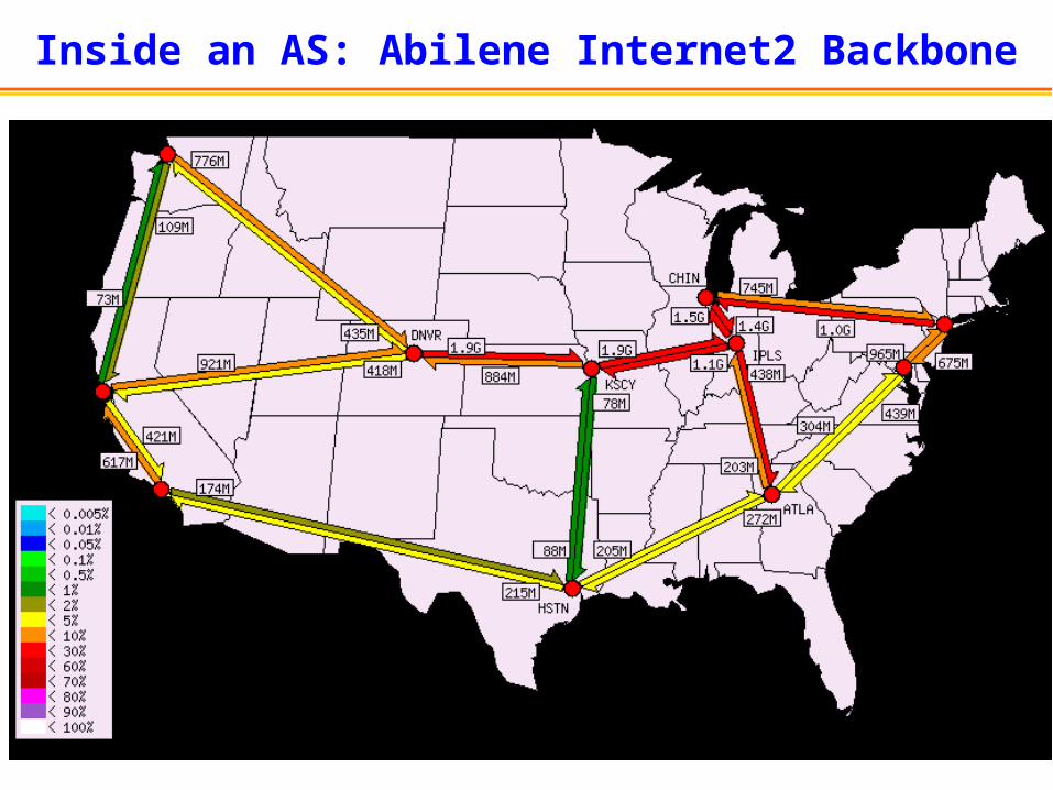
Inside an AS: Abilene Internet2 Backbone

Intradomain Routing (Within an AS)
• Routers exchange topology information– Routers compute “next hop” to other routers– Path chosen based on link weights (shortest path)
• Link weights configured by network operator– … to control the flow of traffic
32
2
1
13
1
4
5
3

Funny Things About the Internet
• Nobody really knows how big it is– No global registry of the topology
• Hard to know what traffic it carries– New applications try to hide their identity
• Built based on trust in others– Do congestion control, announce only the
addresses you own, and so on• Operators do a lot of things manually
– Half of outages are caused by operator error• Diagnosing performance problems is hard
– So many things can go wrong, in so many places
Learn More
• COS 461, spring 2006– MW 1:30-2:50pm
Recommended