COMPUTERCOMMUNICATIONSunggu LeeEE Dept., POSTECHApr. 22, 2009
Computer Communication Example
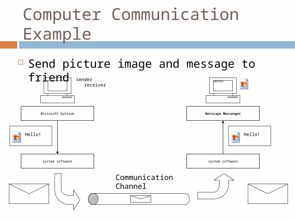
Send picture image and message to friend
Microsoft Outlook
system software
Hello!
Netscape Messenger
system software
Hello!
Hello!
Netscape Messenger
sender receiver
CommunicationChannel
Packetization of Data
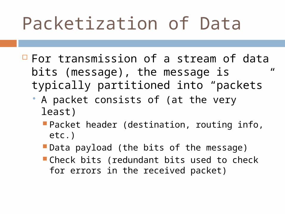
For transmission of a stream of data bits (message), the message is typically partitioned into “packets” A packet consists of (at the very least)
Packet header (destination, routing info, etc.) Data payload (the bits of the message) Check bits (redundant bits used to check for
errors in the received packet)

Communication Protocols
For successful transmission/receipt of a packet, the transmitter and receiver must agree on a “communication protocol” Set of rules on how the packet is interpreted
How to sample the bits of the packet Signaling method Synchronization of the transmitter/receiver
How to determine which parts of the packet are the packet header (destination info, etc.), data payload, check bits, etc.
How to interpret the bits of the data payload Integer, floating-point, character string, JPEG picture, etc.

Computer Communication Models and Communication Protocol Suites
Most commonly used reference base communication model is the Open Systems Interconnection (OSI) model Standardized by the International Organization
for Standardization (ISO) Most common implementation of the OSI
model is a set of protocols referred to as the TCP/IP protocol suite (or stack) TCP = Transmission Control Protocol IP = Internet Protocol

Communication Protocols
ApplicationApplication
PresentationPresentation
SessionSession
TransportTransport
NetworkNetwork
Data LinkData Link
PhysicalPhysical
Protocol forUnderlyingNetwork
Protocol forUnderlyingNetwork
OSI Model TCP/IP Protocol Suite
TCP UDP
SMTP FTPTELNET
DNS SNMP NFS HTTP
RPC
InternetProtocol(IP)
InternetProtocol(IP)
IPICMP IGMP
RARPARP
Ethernet ATMTokenRing . . .
L1
L2
L3
L4
L5
L7
L6
[Forouzan 2003]
001100110000111100001111000
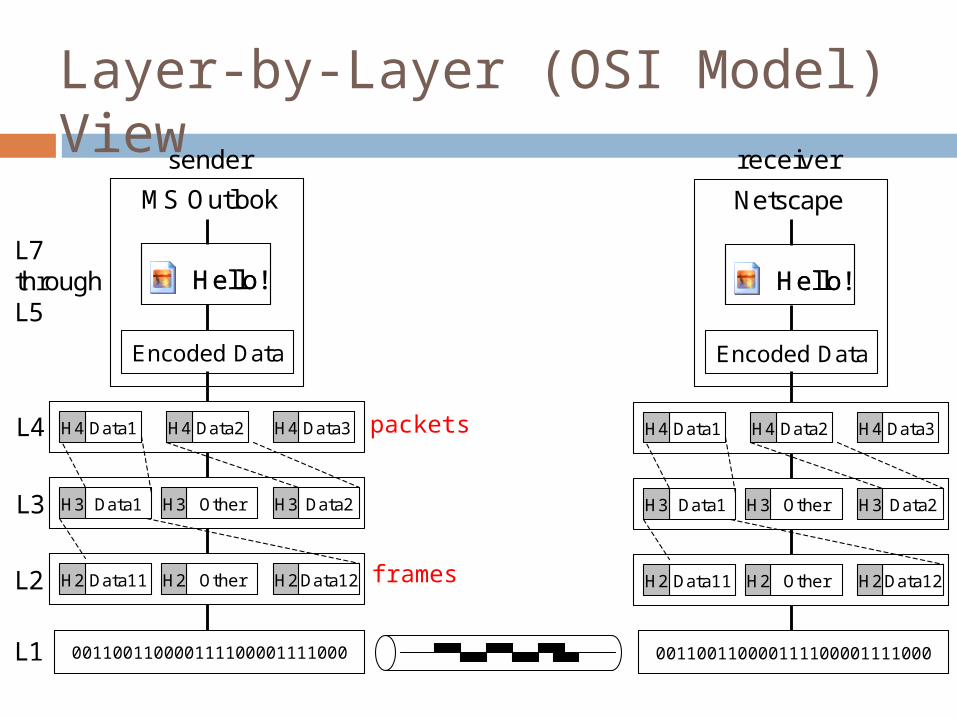
sender
Hello!Hello!
Encoded Data
MS Outlook
Data1H4 Data2H4 Data3H4
Data1H3 OtherH3 Data2H3
Data11H2 OtherH2 Data12H2
receiver
L7throughL5
L4
L3
L2
L1 001100110000111100001111000
Hello!Hello!
Encoded Data
Netscape
Data1H4 Data2H4 Data3H4
Data1H3 OtherH3 Data2H3
Data11H2 OtherH2 Data12H2
Layer-by-Layer (OSI Model) View
packets
frames

Activities Required (Sender Side) Edit message and enter “send” MS Outlook Express Convert into sequence of bits
Tags must be inserted so that original message can be reconstructed at destination E.g., “string” 01001000 … “JPEG” 110011101010 … “end”
11001100100010 … 101011111100 … 01111110 Encrypt message if necessary for privacy Compress if necessary Partition into packets of fixed maximum size
Attach header information (Packet ID, destination, checksum, …) Intersperse with packets from messages created by other
applications On first link of path,
Partition each packet into fixed-size frames (with headers) Send each frame out onto the network
IP address

Activities Required on Network Route each packet to its destination During each “hop” of the path
Send signals back and forth to coordinate the sending and receiving of the stream of bits corresponding to a frame Handshaking
Check each frame for errors Request retransmission in the case of errors
Arrange received frames into the proper order Wait for all frames of the packet to be received
Once each packet reaches its destination node, Store packet in a memory buffer at destination Send signal to destination CPU to inform it of the arrival
of the new packet
Port Number
IP address

Activities at Destination Node Receive packets
Check each packet for errors and request retransmission in the case of errors
Arrange received packets into the proper order Once all packets have been received, form a complete
message Decompress if necessary Decrypt if necessary Check for errors Use tags in the bit stream to reconstruct the
message Show message to user using email tool (e.g., MS
Outlook Express)

Network Addresses
IP (Internet Protocol) address Address used to identify a computing node on the internet Network layer (L3) address E.g., 141.223.165.189 (Look up “properties” on “TCP/IP” on
“Network”) MAC (Medium Access Control) address
Address used to identify a LAN card – cannot be changed Data link layer (L2) address E.g., abcd1234 (Enter “ipconfig /all” from MS Windows “cmd”
window) Port address
Address used to identify a network interface point for an application prog.
Corresponds to a memory buffer Send a message - write to a memory buffer on a remote computer Receive a message – read from a memory buffer on the local computer
Example: 39 (for FTP), 3000 (for a user-defined port)
Connection-Oriented and Connectionless Networking Connection-oriented networking
Uses a specific network path that is established for the duration of a connection Three phases: connection establishment, data transfer,
connection termination Main advantage: reliable communication Main implementation method: TCP (transfer control
protocol) Used in the “parallel merge sort” socket-based program (TCP
sockets interface)
Connectionless networking Finds a new path for each packet sent Main advantage: fast communication for short messages Main implementation method: UDP (user datagram
protocol)
Communication Performance Parameters (1)
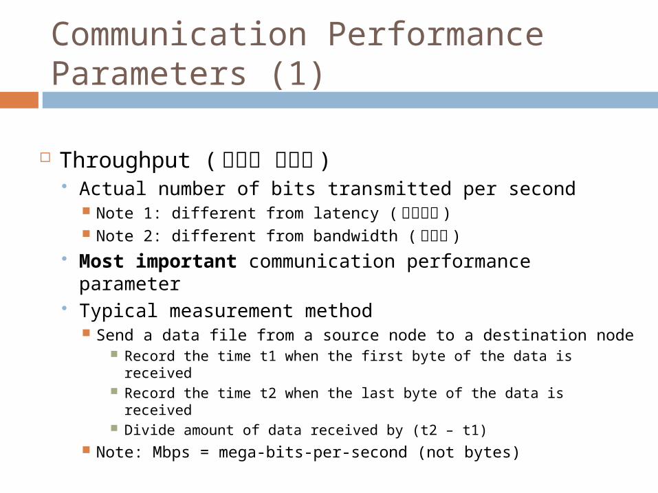
Throughput ( 데이터 처리량 ) Actual number of bits transmitted per second
Note 1: different from latency ( 지연시간 ) Note 2: different from bandwidth ( 대역폭 )
Most important communication performance parameter
Typical measurement method Send a data file from a source node to a destination node
Record the time t1 when the first byte of the data is received
Record the time t2 when the last byte of the data is received Divide amount of data received by (t2 – t1)
Note: Mbps = mega-bits-per-second (not bytes)

Communication Performance Parameters (2)
Bandwidth Maximum number of bits that can be transmitted
per second Note 1: different from latency ( 지연 시간 ) Note 2: different from throughput ( 데이터 처리량 )
Measures performance of network only (not the computer hardware or software)
Typical measurement method Difficult to measure since effects of small data amounts,
software and hardware at source and destination nodes must be removed
The “rated” figure stated in the specifications for the relevant communication protocol is most commonly used
E.g., 11 Mbps for IEEE 802.11b

Communication Performance Parameters (3)
Latency Time required for the first byte of a message to
be transferred from the source to the destination node
Should include software processing time Typical measurement method
At time t1, source node sends a very small message to destination node
Destination node receives message and sends it back to the source node
Source node receives message and records the time t2 One-way communication latency is (t2 – t1) / 2 Why can’t we measure latency directly (record time t3 at
destination and measure latency as t3 – t1)?
Computer Communication Example (Revisited)
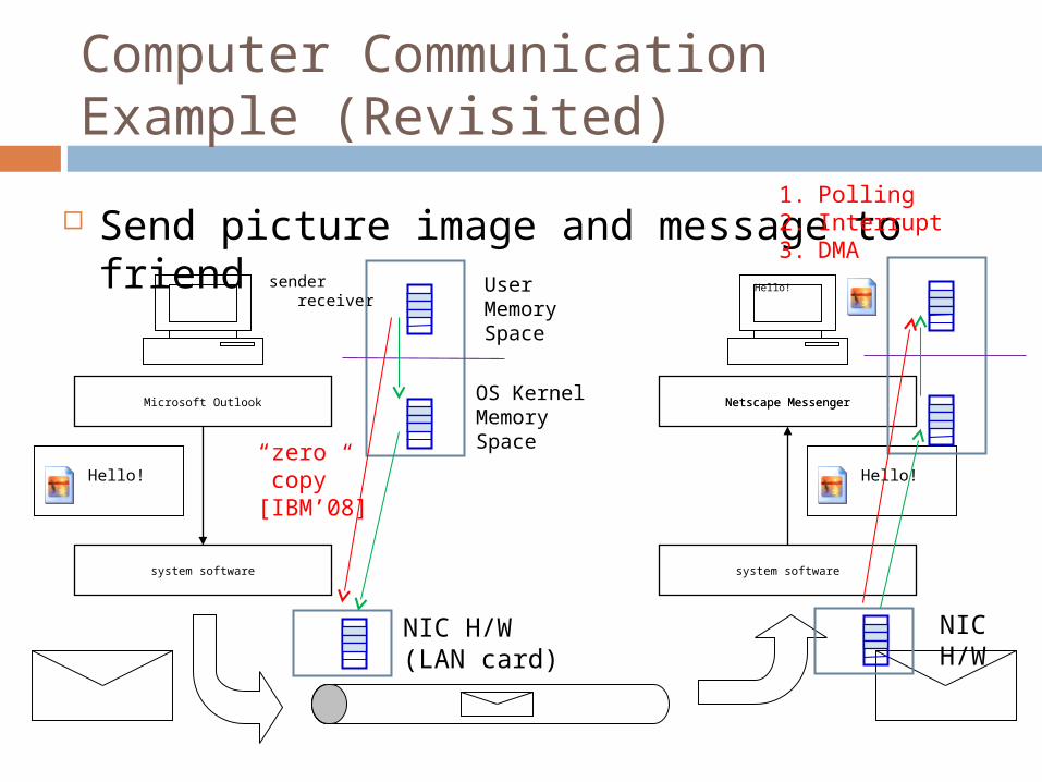
Send picture image and message to friend
Microsoft Outlook
system software
Hello!
Netscape Messenger
system software
Hello!
Hello!
Netscape Messenger
sender receiver
NIC H/W(LAN card)
UserMemorySpace
OS KernelMemorySpace
NICH/W
1. Polling2. Interrupt3. DMA
“zero copy”[IBM’08]
EECE 550
17
Section 7.8 of [Culler 1999]
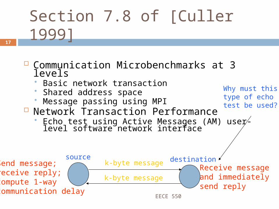
Communication Microbenchmarks at 3 levels Basic network transaction Shared address space Message passing using MPI
Network Transaction Performance Echo test using Active Messages (AM) user-level
software network interface
source destinationk-byte message
k-byte messageReceive messageand immediatelysend reply
Send message;receive reply;compute 1-waycommunication delay
Why must thistype of echotest be used?

EECE 550
18
LogP Communication Model
LogP model used for network transaction performance modeling L latency (within the physical network) o overhead (= sending overhead + receiving
overhead) g gap (the minimum gap between consecutive
message send operations) P processing time (for normal processing of
application programs) Refer to Figs. 7.30 and 7.31 [Culler 1999]

EECE 550
19
Message-Passing Operations Simple model for overall time to send n bytes
T(n) = T0 + n/B T0 is time to send initial byte of data over the network
Sending overhead + receiving overhead n is number of bytes B is the bandwidth of the network link
rinfinity : asymptotic bandwidth n½ : transfer size at which throughput = ½ *
rinfinity

EECE 550 20
Table 7.1 of [Culler 1999]: progressive improvement in T0, B, MFLOPS/processor Berkeley NOW
T0 = 6 microseconds rinfinity = 120 MB/s (Megabytes per second)

EECE 550
21
Application-Level Performance How does LogP affect application performance?
Depends on the characteristics of the application General trends observable Figures 7.35, 7.36, 7.37, 7.38 and Table 7.2 [Culler
1999] T0 large larger messages are preferable T0 small, B large small messages are acceptable Larger numbers of processors smaller message
sizes, smaller working sets (size of data that fits into faster memory, such as one cache line)

EECE 550
22
Synchronization Issues
Message-Passing Model Locks are not necessary since mutual exclusion is not a
problem Each process has exclusive access to its local memory
and uses message-passing to send/receive data from/to other nodes
Group synchronization and group communication is still a problem
Shared-Address-Space Model Requires basic support for “locks” and “barriers” Software algorithms execute on top of basic atomic
exchange primitives Programming environment/hardware must provide
perception of atomic memory operations

EECE 550
23
Group Communication Operations Unicast (one-to-one) Multicast (one-to-many) Broadcast (one-to-all) All-to-all broadcast All-to-all personalized multicast (or broadcast)
Also referred to as “gossiping” Special operations used for performance
improvement Parallel prefix (used with parallel supercomputers) Map-reduce (white paper written by Google
engineers)

Communication Support in the ESA Lab Cluster 1Gbps Ethernet cards and switches Myrinet switches, Myrinet LAN cards (from Myricom)
1.28 Gbps/port TCP/IP, Myrinet GM and BIP LAN interface software [Kim
2001] Myrinet2000 switch and Myrinet2000 LAN cards
2.0 Gbps/port bandwidth (= 250MBps) TCP sockets
> 100 microsecond latency, much less than peak BW Myrinet GM LAN interface software (www.myricom.com)
Around 5 microsecond latency, close to peak BW Note: current (2009) state-of-art is Myrinet10G, MX S/W
Around 2 microsecond latency, close to 10Gbps throughput
References
Behrouz A. Forouzan, TCP/IP Protocol Suite, 2nd Ed., McGraw-Hill, Boston, 2003.
D. E. Culler, J. P. Singh and A. Gupta, Parallel Computer Architecture: A Hardware/Software Approach, Morgan Kaufmann, San Francisco, 1999.
http://www.ibm.com/developerworks/linux/library/j-zerocopy/ , 2008.
S. C. Kim and S. Lee, ``Measurement and prediction of communication latencies in Myrinet networks,'' J. Parallel and Distributed Computing, Vol. 61, No. 11, pp. 1692-1704, November 2001.
Recommended