
Compresor lg de 24000 BTU modelo QP325KCB

Compresor lg de 24000 BTU modelo QP325KCB

DataRev. No
Rev. description Write
0.Revision History
2 / 13
Ref. No. LGETA-140115-1576
Issued Date 2014.01.15
Rev. No. Rev. 0
Rev. Date -
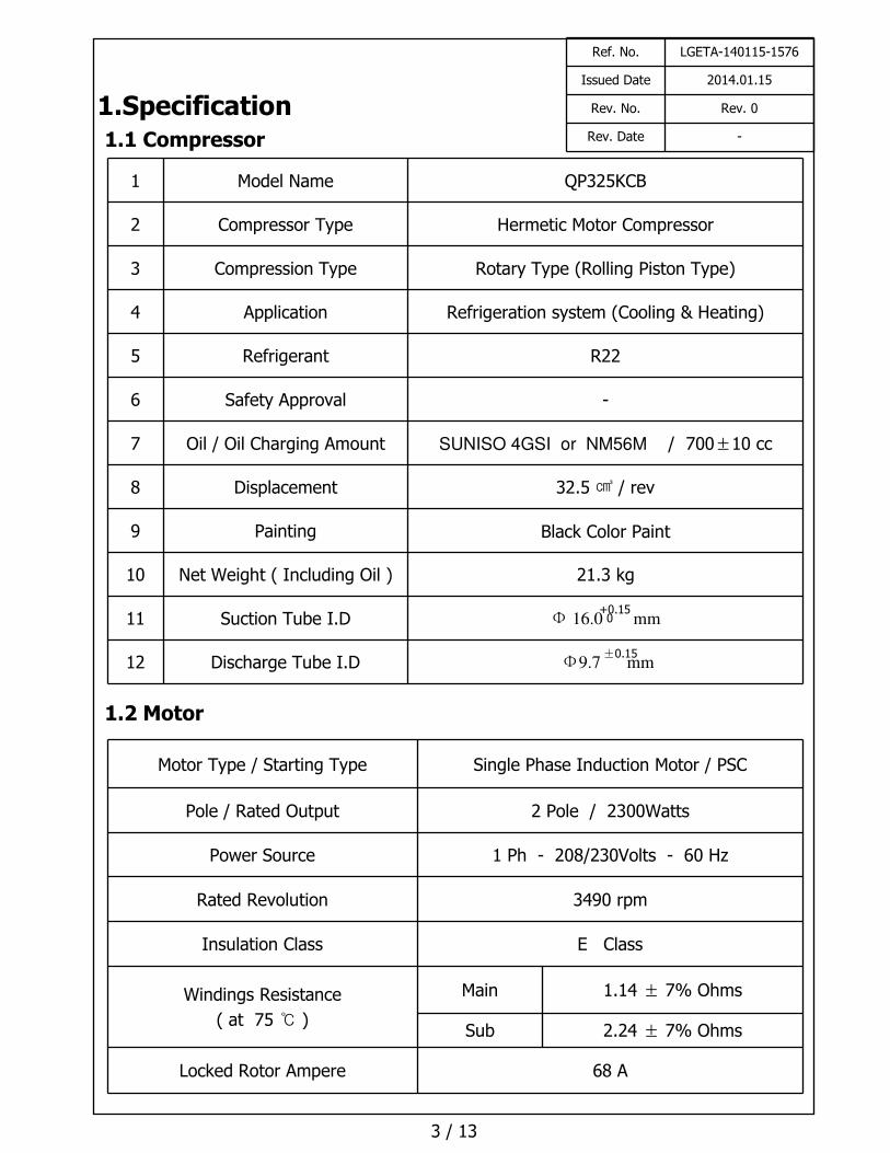
1.Specification
1.1 Compressor
1.2 Motor
1 Model Name QP325KCB
2 Compressor Type Hermetic Motor Compressor
3 Compression Type Rotary Type (Rolling Piston Type)
4 Application Refrigeration system (Cooling & Heating)
5 Refrigerant R22
6 Safety Approval -
7 Oil / Oil Charging Amount SUNISO 4GSI or NM56M / 700±10 cc
8 Displacement 32.5 ㎤ / rev
9 Painting Black Color Paint
10 Net Weight ( Including Oil ) 21.3 kg
11 Suction Tube I.D Φ 16.0 mm
12 Discharge Tube I.D Φ9.7 mm
Motor Type / Starting Type Single Phase Induction Motor / PSC
Pole / Rated Output 2 Pole / 2300Watts
Power Source 1 Ph - 208/230Volts - 60 Hz
Rated Revolution 3490 rpm
Insulation Class E Class
Windings Resistance
( at 75 ℃ )
Main 1.14 ± 7% Ohms
Sub 2.24 ± 7% Ohms
Locked Rotor Ampere 68 A
3 / 13
Ref. No. LGETA-140115-1576
Issued Date 2014.01.15
Rev. No. Rev. 0
Rev. Date -
+0.150
±0.15

1.3 Wiring diagram
1.5 Performance
Voltage At 220 V
Cooling Capacity (-5%↑) [ BTU/h ] 23,700
[ W/h ] 6,945
Power Input (+5%↓) [ W ] 2,267
EER (-5%↑) [ BTU/Whr ]
[ W / W ]
10.5
3.06
Running Current [ A ] 11.0
☞ Rated Conditions (ASHRAE-T Condition)
Cond. Temp. : 54.4 ℃ ( 130 ℉ )Evap. Temp. : 7.2 ℃ ( 45 ℉ )
Return Gas Temp. : 35.0 ℃ ( 95 ℉ )Liquid Temp. : 46.1 ℃ ( 115 ℉ )Ambient Temp. : 35.0 ℃ ( 95 ℉ )
4 / 13
Running Capacitor 50 MFD / 400 VAC
Over Load Protector Internal (3HM-601)
1.4 Electrical Component
※ Make Sure to connect right way same with the wiring diagram.
Ref. No. LGETA-140115-1576
Issued Date 2014.01.15
Rev. No. Rev. 0
Rev. Date -
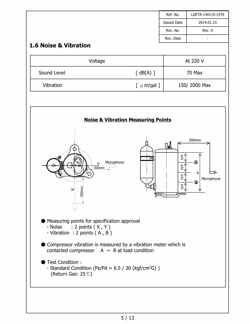
Noise & Vibration Measuring Points
● Measuring points for specification approval- Noise : 2 points ( X , Y )- Vibration : 2 points ( A , B )
● Compressor vibration is measured by a vibration meter which is contacted compressor A ~ B at load condition
● Test Condition : - Standard Condition (Ps/Pd = 6.5 / 30 (kgf/cm2G) )
(Return Gas: 25℃)
Microphone
X
Y300mm
300m
m
Microphone
300mm
H/4
H/4
H/4
H/4
H
B
A
1.6 Noise & Vibration
Voltage At 220 V
Sound Level [ dB(A) ] 70 Max
Vibration [ μm/gal ] 150/ 2000 Max
5 / 13
Ref. No. LGETA-140115-1576
Issued Date 2014.01.15
Rev. No. Rev. 0
Rev. Date -
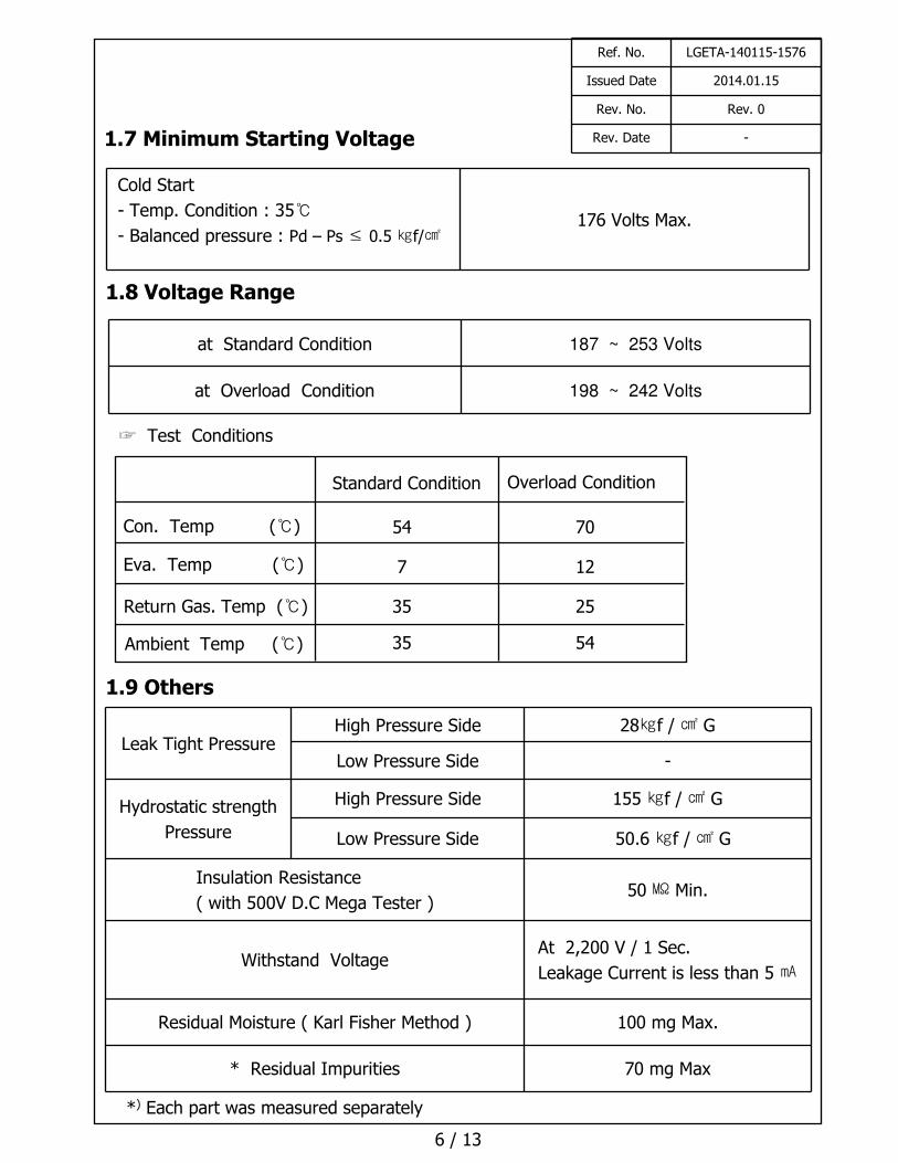
1.7 Minimum Starting Voltage
Leak Tight PressureHigh Pressure Side 28㎏f / ㎠ G
Low Pressure Side -
Hydrostatic strength
Pressure
High Pressure Side 155 ㎏f / ㎠ G
Low Pressure Side 50.6 ㎏f / ㎠ G
Insulation Resistance
( with 500V D.C Mega Tester )50 ㏁ Min.
Withstand VoltageAt 2,200 V / 1 Sec.
Leakage Current is less than 5 ㎃
Residual Moisture ( Karl Fisher Method ) 100 mg Max.
* Residual Impurities 70 mg Max
Cold Start
- Temp. Condition : 35℃
- Balanced pressure : Pd – Ps ≤ 0.5 ㎏f/㎠176 Volts Max.
at Standard Condition 187 ~ 253 Volts
at Overload Condition 198 ~ 242 Volts
*) Each part was measured separately
1.8 Voltage Range
6 / 13
1.9 Others
☞ Test Conditions
Standard Condition Overload Condition
Con. Temp (℃)
Eva. Temp (℃)
Return Gas. Temp (℃)
Ambient Temp (℃)
54 70
7 12
35 25
35 54
Ref. No. LGETA-140115-1576
Issued Date 2014.01.15
Rev. No. Rev. 0
Rev. Date -
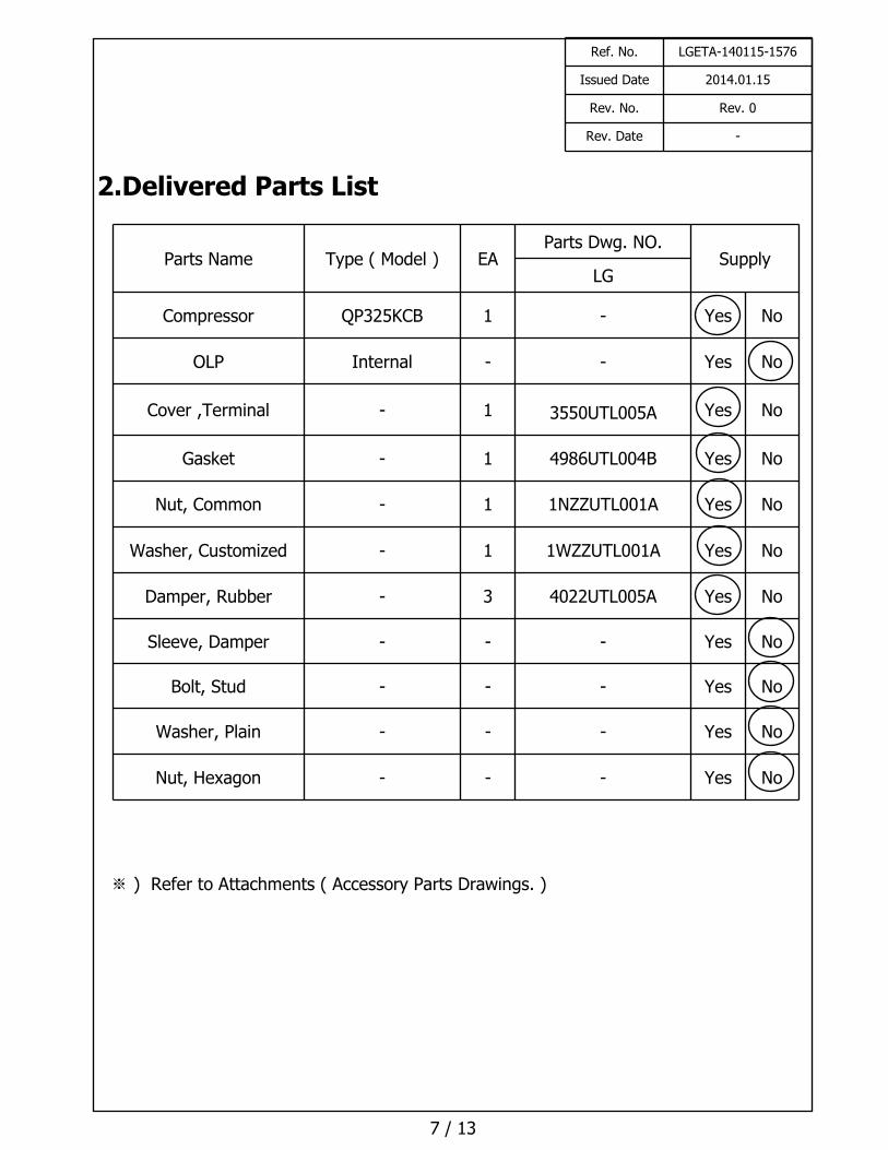
2.Delivered Parts List
※ ) Refer to Attachments ( Accessory Parts Drawings. )
7 / 13
Parts Name Type ( Model ) EAParts Dwg. NO.
SupplyLG
Compressor QP325KCB 1 - Yes No
OLP Internal - - Yes No
Cover ,Terminal - 1 3550UTL005A Yes No
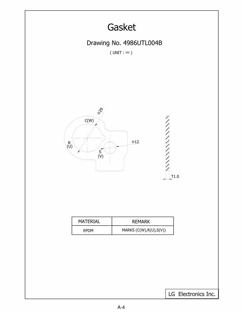
Gasket - 1 4986UTL004B Yes No
Nut, Common - 1 1NZZUTL001A Yes No
Washer, Customized - 1 1WZZUTL001A Yes No
Damper, Rubber - 3 4022UTL005A Yes No
Sleeve, Damper - - - Yes No
Bolt, Stud - - - Yes No
Washer, Plain - - - Yes No
Nut, Hexagon - - - Yes No
Ref. No. LGETA-140115-1576
Issued Date 2014.01.15
Rev. No. Rev. 0
Rev. Date -
3.Operating Limit
8 / 13
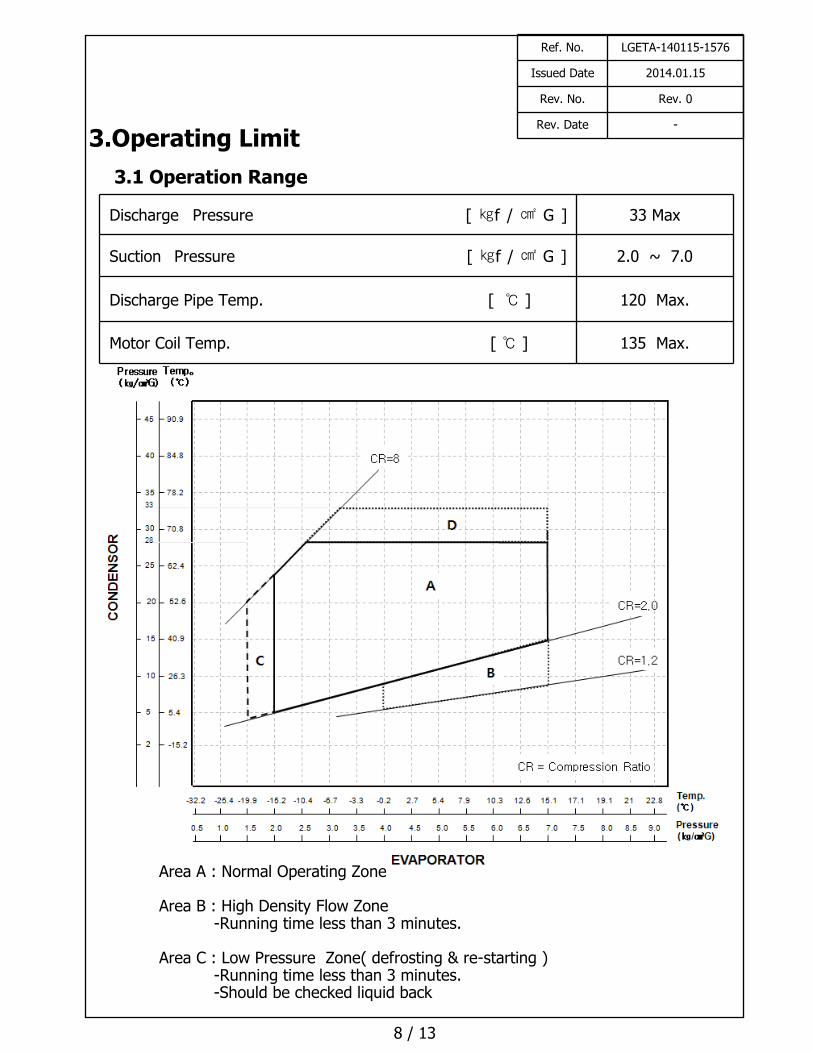
Discharge Pressure [ ㎏f / ㎠ G ] 33 Max
Suction Pressure [ ㎏f / ㎠ G ] 2.0 ~ 7.0
Discharge Pipe Temp. [ ℃ ] 120 Max.
Motor Coil Temp. [ ℃ ] 135 Max.
3.1 Operation Range
Area A : Normal Operating Zone
Area B : High Density Flow Zone-Running time less than 3 minutes.
Area C : Low Pressure Zone( defrosting & re-starting )-Running time less than 3 minutes. -Should be checked liquid back
Ref. No. LGETA-140115-1576
Issued Date 2014.01.15
Rev. No. Rev. 0
Rev. Date -
Refrigerant
Charge Limit
Cooling Only for SRAC system : 1866g Max
(Charge limit depends on Oil Dilution Rate *note 1 & accumulator ‘K’)
Liquid
Refrigerant Back
System should be designed not to allow the liquid to go back to
compressor which cause knocking noise , current increase or undesirable
vibration and make short compressor life time.
Δ T :
Temp. Difference
Δ T = Case Bottom Temp.- Condensing Temp.
It must be kept Δ T ≥ 5℃
Pressure
Difference
in Operating
The Pressure difference in operating shall be 5.0㎏f/㎠ or more, but 3
minutes starting excluded.
ON/OFF
OperationEach cycle should be at least 6 minutes
(ON Time : at least 3 minute , OFF Time : at least 3 minutes)
Pressure
Difference
at Starting
When starting, discharge pressure is balanced with suction pressure.
( Pd – Ps ≤ 0.5 ㎏f/㎠ )
Tilt in Operation The allowable tilt of the compressor in operation shall be 5˚ or less.
System
Accumulator
The Accumulator volume should be enough to cover 30% of maximum
system refrigerant volume.
Ratio coefficient ‘K’ should be over 0.6(heating system) or 0.4(cooling
system)
Volume of Accum.(Comp+System) × Specific gravity of RefrigerantK = ----------------------------------------------------------------------
Charged Weight of Refrigerant
※ Effective volume of compressor accumulator =597 ㎤※ Specific gravity of refrigerant (R22) = 1.25 g/㎤ ( at 20℃ )
If coefficient “K” does not meet recommendation, refrigerant system must check liquid back phenomenon at accumulator.
Protecting
Reverse
Operation
The compressor must be operated by proper voltage in accordance with
the frequency without reverse revolution condition. The reverse
revolution condition can be avoided by just keeping right order of phase
supplied power source.
9 / 13
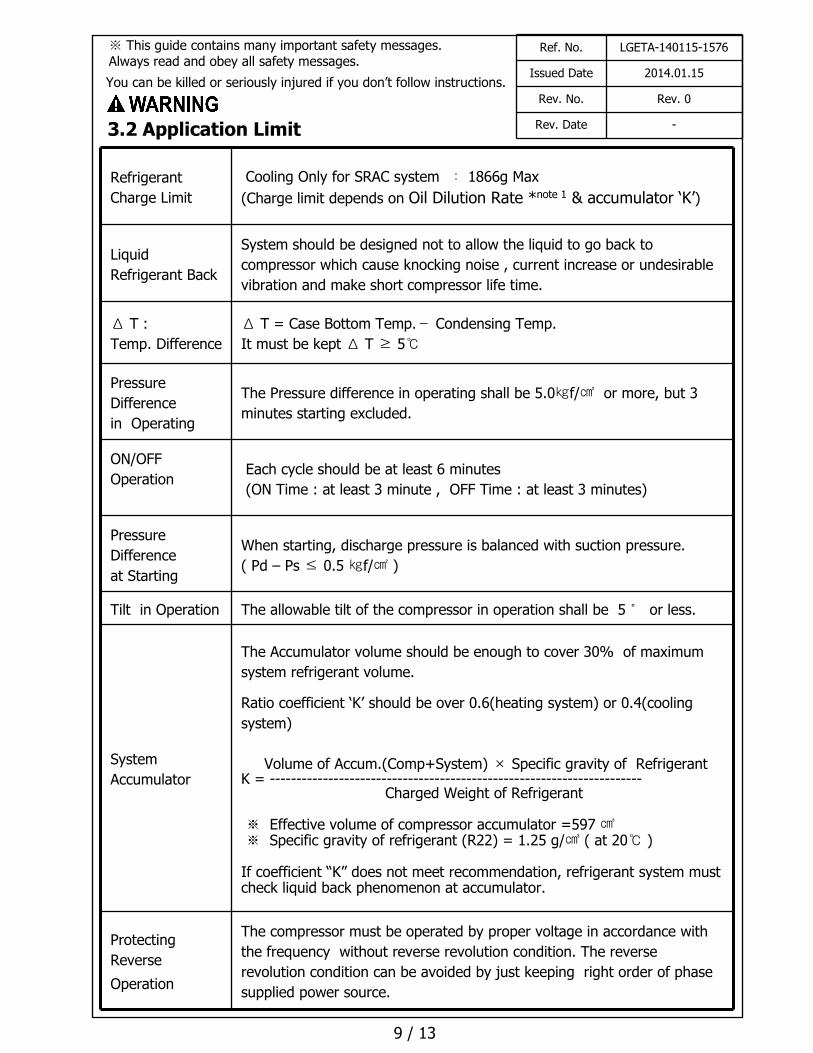
3.2 Application Limit
Ref. No. LGETA-140115-1576
Issued Date 2014.01.15
Rev. No. Rev. 0
Rev. Date -
※ This guide contains many important safety messages. Always read and obey all safety messages.
You can be killed or seriously injured if you don’t follow instructions.
* Effective Period of This Document *
This document will be effective after LG’s receipt with your authorized signature.When design modification is approved by the customer, the current document is unavailable.
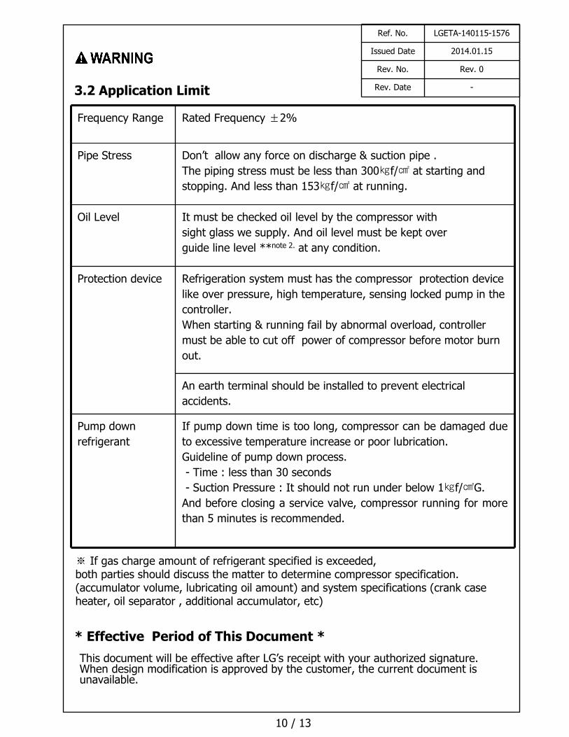
Frequency Range Rated Frequency ±2%
Pipe Stress Don’t allow any force on discharge & suction pipe .
The piping stress must be less than 300㎏f/㎠ at starting and
stopping. And less than 153㎏f/㎠ at running.
Oil Level It must be checked oil level by the compressor with
sight glass we supply. And oil level must be kept over
guide line level **note 2. at any condition.
Protection device Refrigeration system must has the compressor protection device
like over pressure, high temperature, sensing locked pump in the
controller.
When starting & running fail by abnormal overload, controller
must be able to cut off power of compressor before motor burn
out.
An earth terminal should be installed to prevent electrical
accidents.
Pump down
refrigerant
If pump down time is too long, compressor can be damaged due
to excessive temperature increase or poor lubrication.
Guideline of pump down process.
- Time : less than 30 seconds
- Suction Pressure : It should not run under below 1㎏f/㎠G.
And before closing a service valve, compressor running for more
than 5 minutes is recommended.
10 / 13
※ If gas charge amount of refrigerant specified is exceeded, both parties should discuss the matter to determine compressor specification.(accumulator volume, lubricating oil amount) and system specifications (crank case heater, oil separator , additional accumulator, etc)
3.2 Application Limit
Ref. No. LGETA-140115-1576
Issued Date 2014.01.15
Rev. No. Rev. 0
Rev. Date -
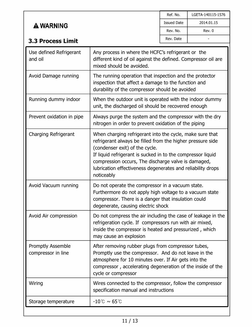
Use defined Refrigerant
and oil
Any process in where the HCFC’s refrigerant or the
different kind of oil against the defined. Compressor oil are
mixed should be avoided.
Avoid Damage running The running operation that inspection and the protector
inspection that affect a damage to the function and
durability of the compressor should be avoided
Running dummy indoor When the outdoor unit is operated with the indoor dummy
unit, the discharged oil should be recovered enough
Prevent oxidation in pipe Always purge the system and the compressor with the dry
nitrogen in order to prevent oxidation of the piping
Charging Refrigerant When charging refrigerant into the cycle, make sure that
refrigerant always be filled from the higher pressure side
(condenser exit) of the cycle.
If liquid refrigerant is sucked in to the compressor liquid
compression occurs, The discharge valve is damaged,
lubrication effectiveness degenerates and reliability drops
noticeably
Avoid Vacuum running Do not operate the compressor in a vacuum state.
Furthermore do not apply high voltage to a vacuum state
compressor. There is a danger that insulation could
degenerate, causing electric shock
Avoid Air compression Do not compress the air including the case of leakage in the
refrigeration cycle. If compressors run with air mixed,
inside the compressor is heated and pressurized , which
may cause an explosion
Promptly Assemble
compressor in line
After removing rubber plugs from compressor tubes,
Promptly use the compressor. And do not leave in the
atmosphere for 10 minutes over. If Air gets into the
compressor , accelerating degeneration of the inside of the
cycle or compressor
Wiring Wires connected to the compressor, follow the compressor
specification manual and instructions
Storage temperature -10℃ ~ 65℃
11 / 13
3.3 Process Limit
Ref. No. LGETA-140115-1576
Issued Date 2014.01.15
Rev. No. Rev. 0
Rev. Date -
* Effective Period of This Document *
This document will be effective after LG’s receipt with your authorized signature.When design modification is approved by the customer, the current document is unavailable.
12 / 13
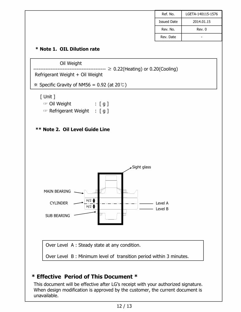
** Note 2. Oil Level Guide Line
* Note 1. OIL Dilution rate
Oil Weight------------------------------------------ ≥ 0.22(Heating) or 0.20(Cooling) Refrigerant Weight + Oil Weight
※ Specific Gravity of NM56 = 0.92 (at 20℃)
[ Unit ]
☞ Oil Weight : [ g ]
☞ Refrigerant Weight : [ g ]
Over Level A : Steady state at any condition.
Over Level B : Minimum level of transition period within 3 minutes.
Level A
Level B
Sight glass
H/2
H/2
SUB BEARING
CYLINDER
MAIN BEARING
Ref. No. LGETA-140115-1576
Issued Date 2014.01.15
Rev. No. Rev. 0
Rev. Date -
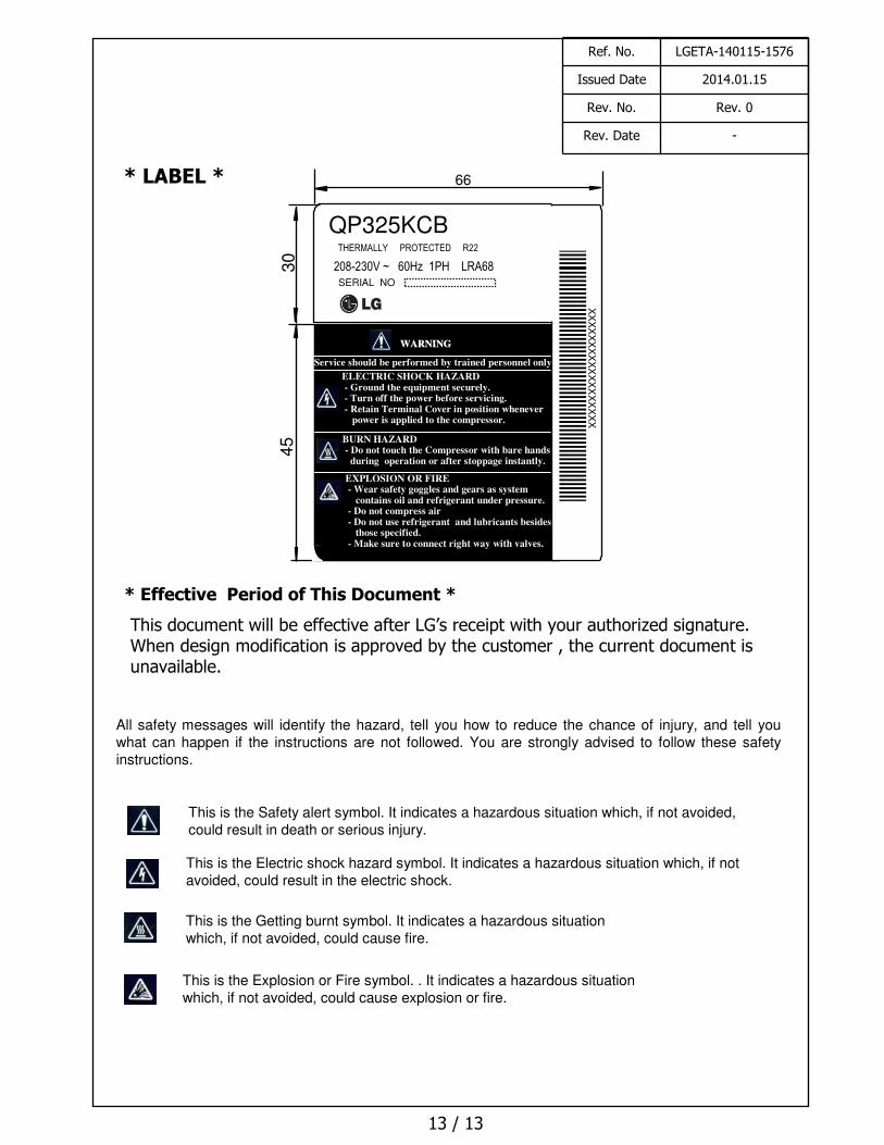
* LABEL *
* Effective Period of This Document *
This document will be effective after LG’s receipt with your authorized signature.When design modification is approved by the customer , the current document isunavailable.
13 / 13
EXPLOSION OR FIRE- Wear safety goggles and gears as systemcontains oil and refrigerant under pressure- Do not compress air.- Do not use refrigerant and lubricants besidesthose specified.
- Make sure to connect right way with valves.
30
45
WARNINGWARNING
ELECTRIC SHOCK HAZARD - Ground the equipment securely.- Turn off the power before servicing.- Retain Terminal Cover in position whenever
power is applied to the compressor.
Service should be performed by trained personnel only .
BURN HAZARD- Do not touch the Compressor with bare hands
during operation or after stoppage instantly.
EXPLOSION OR FIRE- Wear safety goggles and gears as system
contains oil and refrigerant under pressure.- Do not compress air- Do not use refrigerant and lubricants besides
those specified.- Make sure to connect right way with valves.
66
QP325KCBTHERMALLY PROTECTED R22
SERIAL NOX
XX
XX
XX
XX
XX
XX
XX
XX
X
Ref. No. LGETA-140115-1576
Issued Date 2014.01.15
Rev. No. Rev. 0
Rev. Date -
208-230V ~ 60Hz 1PH LRA68
All safety messages will identify the hazard, tell you how to reduce the chance of injury, and tell you what can happen if the instructions are not followed. You are strongly advised to follow these safety instructions.
This is the Safety alert symbol. It indicates a hazardous situation which, if not avoided, could result in death or serious injury.
This is the Electric shock hazard symbol. It indicates a hazardous situation which, if not avoided, could result in the electric shock.
This is the Getting burnt symbol. It indicates a hazardous situation which, if not avoided, could cause fire.
This is the Explosion or Fire symbol. . It indicates a hazardous situation which, if not avoided, could cause explosion or fire.
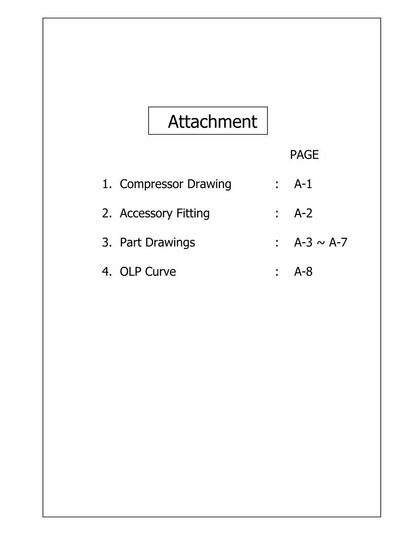
Attachment
PAGE
: A-1
: A-2
: A-3 ~ A-7
: A-8
1. Compressor Drawing
2. Accessory Fitting
3. Part Drawings
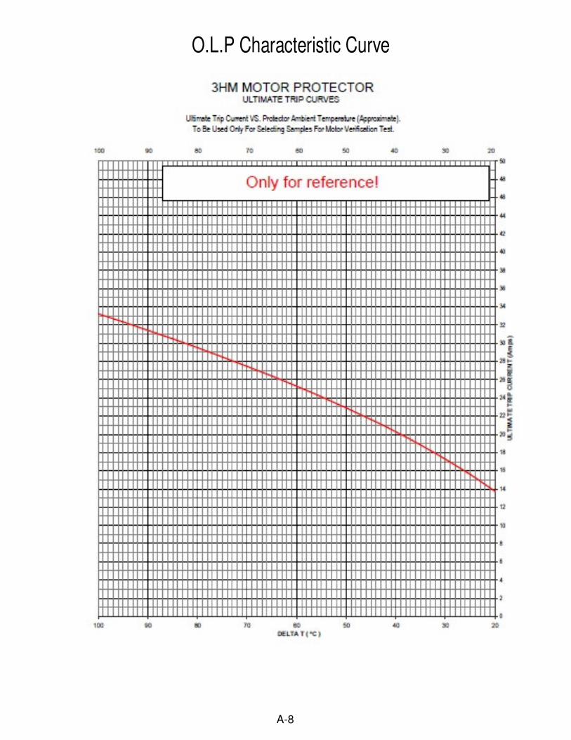
4. OLP Curve
2014.0
1.1
5X.L
.YAN
G
A-1
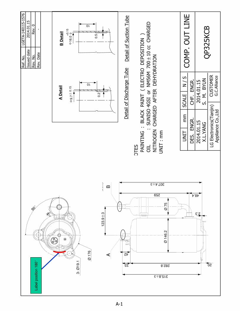
NO
TES
1. P
AIN
TIN
G :
BLACK PAIN
T (
ELECTRO
D
EPO
SIT
ION
)
2. O
IL : S
UN
ISO
4GSI
or
NM
56M
700±
10
cc CH
ARG
ED
3. N
ITRO
GEN
CH
ARG
ED
AFTER D
EH
YD
RATIO
N
4. UN
IT : m
m
Ref. N
o.
Issu
ed d
ate
Rev. No.
Rev. D
ate
LGETA-1
40115-1
576
2014.0
1.1
5
Rev. 0
-
QP325KCB
UN
ITm
mSCALE
N /
S
CH
F. E
NG
R.
DES. E
NG
R.
CUSTO
MER
G.C
.Alli
ance
CO
MP. O
UT L
INE
2014.0
1.1
5S. M
. B
YUN
LG E
lect
ronic
s(Tia
njin)
Applia
nce
Co.,Ltd
Deta
il of Suct
ion T
ube
Deta
il of D
isch
arg
e T
ube
A D
eta
ilB
Deta
il
SU
C.
I.D
+0.15
DIS
. I.
D
±3
0
Φ147.2
Φ75
±3
+0.15
±3
0
La
bel po
sitio
n 1
80° Ø
17
6
3-
Ø1
9.1
90°
BA
315.8±3
282.833
42
20
48.4
307.4±3
2.3
Ø7
5Ø
14
6.2
12
3.9±
3
259
Ф16.0
10
0.5+
0.1
50
Ф9.7
10
0.2±
0.1
5

A-2
Accessory Fitting
LG Electronics Inc.
Accessory Fitting
○◐
○◐
POWERSUPPLY
RUNNINGCAPACITOR
HERMETICTERMINAL
C
R S
Cover Terminal
C ( W )
( U )R S
( V )
C,S,R mark embossed on cover terminal
Gasket
Cover Terminal
Washer, Plain Cover Nut, Hexagon Flange

A-3
Cover, Terminal
Drawing No. 3550UTL005A( UNIT : ㎜ )
LG Electronics Inc.
COLORMATERIAL REMARK
MARKS(C(W),R(U),S(V))BLACKLumax
(22.8)
(29.2)5
(11.
5)
2.1
33.5
2.12.1
S VR
21 .8
(
)
C(
)
120.0⊂
(U)
120.0⊂
W
Ø 34.4
Ø 38.6
A-4
Gasket
Drawing No. 4986UTL004B
( UNIT : ㎜ )
LG Electronics Inc.
MATERIAL REMARK
MARKS (C(W),R(U),S(V))EPDM
(V)
(W)C
S
T1.0
R(U)
Φ12
Φ29

5.5
Φ12
8
9.2
* MATERIAL : STEEL ( ELECTRIC PLATING OF ZINC )
Nut, Common
Drawing No. 1NZZUTL001A
( UNIT : ㎜ )
LG Electronics Inc.
A-5
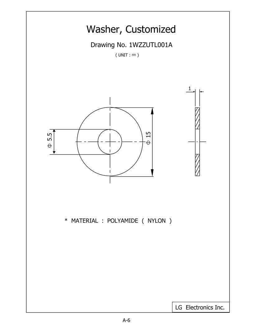
* MATERIAL : POLYAMIDE ( NYLON )
Washer, Customized
Drawing No. 1WZZUTL001AΦ
5.5
Φ15
1
( UNIT : ㎜ )
LG Electronics Inc.
A-6
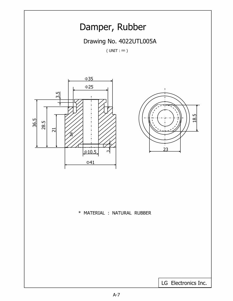
Damper, Rubber
Drawing No. 4022UTL005A
( UNIT : ㎜ )
LG Electronics Inc.
A-7
24
* MATERIAL : NATURAL RUBBER
18.5
23
36.5
Φ10.5 3
Φ41
Φ25
Φ35
3.5
28.5
21
A-8
O.L.P Characteristic Curve
Distribuido por:
Recommended


