APPROVED FOR PUBLIC RELEASE—DISTRIBUTION IS UNLIMITED
METRIC/SI (ENGLISH)
NASA TECHNICAL STANDARD
NASA-STD-1008
Office of the NASA Chief Engineer
Approved: 2021-09-21
CLASSIFICATIONS AND REQUIREMENTS FOR
TESTING SYSTEMS AND HARDWARE TO BE EXPOSED TO DUST
IN PLANETARY ENVIRONMENTS
Trade names and trademarks are used in this NASA Technical Standard for identification only. Their
usage does not constitute an official endorsement, either expressed or implied, by NASA.
NASA-STD-1008
APPROVED FOR PUBLIC RELEASE—DISTRIBUTION IS UNLIMITED
2 of 99
DOCUMENT HISTORY LOG
Status Document
Revision
Change
Number
Approval Date Description
Baseline 2021-09-21 Initial Release

NASA-STD-1008
APPROVED FOR PUBLIC RELEASE—DISTRIBUTION IS UNLIMITED
3 of 99
FOREWORD
This NASA Technical Standard is published by the National Aeronautics and Space
Administration (NASA) to provide uniform engineering and technical requirements for
processes, procedures, practices, and methods that have been endorsed as standard for NASA
programs and projects, including requirements for selection, application, and design criteria of an
item.
This NASA Technical Standard is approved for use by NASA Headquarters and NASA Centers
and Facilities, and applicable technical requirements may be cited in contract, program, and other
Agency documents. It may also apply to the Jet Propulsion Laboratory (a Federally Funded
Research and Development Center [FFRDC]), other contractors, recipients of grants and
cooperative agreements, and parties to other agreements only to the extent specified or
referenced in applicable contracts, grants, or agreements.
This NASA Technical Standard establishes minimum requirements and provides guidance for
testing systems and hardware to be exposed to dust in planetary environments.
Requests for information should be submitted via “Feedback” at https://standards.nasa.gov.
Requests for changes to this NASA Technical Standard should be submitted via Marshall Space
Flight Center (MSFC) Form 4657, Change Request for a NASA Engineering Standard.
Original Signed by Adam West September 21, 2021
_______________________________ _____________________
for Ralph R. Roe, Jr. Approval Date
NASA Chief Engineer
NASA-STD-1008
APPROVED FOR PUBLIC RELEASE—DISTRIBUTION IS UNLIMITED
4 of 99
TABLE OF CONTENTS
SECTION PAGE
DOCUMENT HISTORY LOG ...................................................................................................... 2 FOREWORD .................................................................................................................................. 3 LIST OF APPENDICES ................................................................................................................. 5
LIST OF FIGURES ........................................................................................................................ 6 LIST OF TABLES .......................................................................................................................... 6
1. SCOPE ................................................................................................................................ 7 1.1 Purpose ................................................................................................................................ 7
1.2 Applicability ....................................................................................................................... 7 1.3 Tailoring .............................................................................................................................. 8
2. APPLICABLE DOCUMENTS .......................................................................................... 9
2.1 General ................................................................................................................................ 9 2.2 Government Documents ..................................................................................................... 9
2.3 Non-Government Documents ............................................................................................. 9 2.4 Order of Precedence ............................................................................................................ 9
3. ACRONYMS, ABBREVIATIONS, SYMBOLS, AND DEFINITIONS ........................ 10 3.1 Acronyms, Abbreviations, and Symbols .......................................................................... 10
3.2 Definitions......................................................................................................................... 11
4. DUST REQUIREMENTS AND STANDARDS.............................................................. 14 4.1 Dust Impact Assessment Process ...................................................................................... 14
4.2 Sources of Dust ................................................................................................................. 19
a. Planetary External (PE) .................................................................................................... 14 (1) Lunar Sources of Dust ...................................................................................................... 23
(2) Martian Sources of Dust ................................................................................................... 23
(3) Small Bodies Sources of Dust........................................................................................... 23
b. Planetary Pressurized (PP) ................................................................................................ 23 (1) Lunar Sources of Dust ...................................................................................................... 23 (2) Martian Sources of Dust ................................................................................................... 25 (3) Small Bodies Sources of Dust........................................................................................... 25 c. In-Space Pressurized (SP) ................................................................................................. 25
(1) Lunar Sources of Dust ...................................................................................................... 25 (2) Martian Sources of Dust ................................................................................................... 27
(3) Small Bodies Sources of Dust........................................................................................... 27 d. In-Space External (SE) ..................................................................................................... 27 (1) Lunar Sources of Dust ...................................................................................................... 27

NASA-STD-1008
APPROVED FOR PUBLIC RELEASE—DISTRIBUTION IS UNLIMITED
5 of 99
TABLE OF CONTENTS (Continued)
SECTION PAGE
(2) Martian Sources of Dust ................................................................................................... 29 (3) Small Bodies Sources of Dust........................................................................................... 29
5. TESTING METHODOLOGIES AND BEST PRACTICES ............................................ 29 5.1 Simulant Preparation and Storage ..................................................................................... 30 5.1.1 Particle Separation ............................................................................................................ 30 5.1.2 Bake-out ............................................................................................................................ 33 5.1.3 Storage .............................................................................................................................. 37
5.2 Simulant Loading Definitions ........................................................................................... 37 5.2.1 Surface-Accumulated Loading ......................................................................................... 38
5.2.2 Volumetric Loading .......................................................................................................... 41 5.3 Testing Practices and Categories ...................................................................................... 41
5.3.1 Aerosol Ingestion Testing ................................................................................................. 42 5.3.2 Abrasion Testing ............................................................................................................... 45
5.3.3 Optical Testing .................................................................................................................. 47 5.3.4 Thermal Testing ................................................................................................................ 49 5.3.5 Mechanisms Testing ......................................................................................................... 52
5.3.6 Seals and Mating Surfaces Testing ................................................................................... 55 5.3.7 Reactivity Testing ............................................................................................................. 56
5.3.8 Electrostatic Properties ..................................................................................................... 60 5.3.9 Plume Surface Interaction Testing .................................................................................... 63
5.4 Simulants........................................................................................................................... 66 5.4.1 Lunar Simulants ................................................................................................................ 66
5.4.2 Martian Simulants ............................................................................................................. 67 5.4.3. Small Bodies Simulants .................................................................................................... 67 5.5 Facilities ............................................................................................................................ 67
LIST OF APPENDICES
APPENDIX PAGE
A Context for Testing the Effects of Dust on Hardware and Systems .................... 69
B Dust Impact Assessment Process Examples ........................................................ 71
C References ............................................................................................................ 75
D Requirements Compliance Matrix ....................................................................... 85

NASA-STD-1008
APPROVED FOR PUBLIC RELEASE—DISTRIBUTION IS UNLIMITED
6 of 99
LIST OF FIGURES
FIGURE PAGE
1 Dust Impact Assessment Process ......................................................................... 15
2 Images of Apollo 17 and 15 Lunar Samples ........................................................ 70
LIST OF TABLES
TABLE PAGE
1 Dust Impact Assessment Process Steps ............................................................... 16
2 Planetary External Lunar Sources of Dust and Associated Dust Parameters ...... 21
3 Planetary Pressurized Lunar Sources of Dust and Associated Dust Parameters . 24
4 In-Space Pressurized Lunar Sources of Dust and Associated Dust Parameters .. 26
5 In-Space External Lunar Sources of Dust and Associated Dust Parameters ....... 28
6 Resistivity Ranges for Conductive, Static Dissipative, and Insulating
Materials...............................................................................................................
61
NASA-STD-1008
APPROVED FOR PUBLIC RELEASE—DISTRIBUTION IS UNLIMITED
7 of 99
CLASSIFICATIONS AND REQUIREMENTS FOR TESTING
SYSTEMS AND HARDWARE TO BE EXPOSED TO DUST IN
PLANETARY ENVIRONMENTS
1. SCOPE
1.1 Purpose
The purpose of this NASA Technical Standard is to establish minimum requirements and
provide effective guidance regarding methodologies and best practices for testing systems and
hardware to be exposed to dust in dust laden and generating environments. The intent is to
facilitate consistency and efficiency in testing space systems, subsystems, or components with
operations and missions in dusty environments.
1.2 Applicability
This NASA Technical Standard is applicable to any system, subsystem, or component that will
be exposed to planetary dust (refer to definition in section 3.2 in this NASA Technical Standard).
There are four different environments in which hardware may be exposed to dust: planetary
external (PE), planetary pressurized (PP) volumes, in-space pressurized (SP) volumes, and in-
space external (SE). In this NASA Technical Standard, the environments are referred to as
working dust environments. The word “pressurized” does not necessarily imply habitable. Where
applicable, habitable volumes are identified in the text of this NASA Technical Standard.
This NASA Technical Standard allows for broad usage for missions to the Moon, Mars, and
small bodies (e.g., asteroids) when working with dust or regolith. However, section 4.2 (Sources
of Dust) and section 5.4 (Simulants) have been broken into Lunar, Martian, and Small Bodies
sections, with the Martian and Small Bodies sections currently marked as reserved.
The environmental conditions defined in this NASA Technical Standard (sources of dust,
particle sizes, system surface, and/or volumetric loading) are based on estimates from current
data sets or studies. Future insight into these environments through missions, technology
demonstrations, laboratory studies, modeling, or analyses may unveil new definitions, at which
time this NASA Technical Standard will be revised. Appendix A provides context for why it is
necessary to test and examine the effects of dust on hardware and systems as it relates to the
operational environment.
The requirements and guidance in this NASA Technical Standard are intended to be applied
whenever dust testing is performed within a program or project, regardless of level of
development (i.e., from design to acceptance to qualification). Additionally, new programs may
use different equipment and operations (e.g., in situ resource utilization [ISRU] excavation) that
produce new sources of dust or different working dust environments. When appropriate, mission-
dependent accommodations and analyses may be needed. Programs should tailor these values for
the specific equipment and operations planned.

NASA-STD-1008
APPROVED FOR PUBLIC RELEASE—DISTRIBUTION IS UNLIMITED
8 of 99
This NASA Technical Standard does not provide guidance for mitigation techniques or
contamination control, and does not provide suggestions or solutions for operating hardware in
dusty environments. As opposed to previously published standards such as ISO 14644-1, which
defines clean room practices, this NASA Technical Standard defines so-called "dirty room"
environments and directs personnel in the identification of a suitable dust environment for
testing. It is left to such personnel to choose an appropriate simulant and define the appropriate
test within that environment based on expected dust size range, volume and/or surface loading,
particular hardware choice, and other parameters as directed by this NASA Technical Standard.
Use SI units where English units are not specified (e.g., for particle sizes, surface loading, and
volumetric loading).
This NASA Technical Standard is approved for use by NASA Headquarters and NASA Centers
and Facilities, and applicable technical requirements may be cited in contract, program, and other
Agency documents. It may also apply to the Jet Propulsion Laboratory (a Federally Funded
Research and Development Center [FFRDC]), other contractors, recipients of grants and
cooperative agreements, and parties to other agreements only to the extent specified or
referenced in applicable contracts, grants, or agreements.
Verifiable requirement statements are designated by the acronym “DTR” (Dust Testing
Requirement), numbered, and indicated by the word “shall”; this NASA Technical Standard
contains 14 requirements. Explanatory or guidance text is indicated in italics beginning in section
4. To facilitate requirements selection by NASA programs and projects, a Requirements
Compliance Matrix is provided in Appendix D.
1.3 Tailoring
Tailoring of the requirements in this NASA Technical Standard for application to a specific
program or project is acceptable when formally approved by the delegated Technical Authority
in accordance with NPR 7120.5, NASA Space Flight Program and Project Management
Requirements, and NPR 7120.8, NASA Research and Technology Program and Project
Management Requirements, and documented in program or project requirements.
Programs/projects are expected to identify necessary hardware, systems, subsystems, and
components that will be subject to this NASA Technical Standard and tailor these requirements
to their hardware, system, subsystem, or component needs to achieve mission success in an
efficient manner. It is unlikely that all requirements and guidelines in this NASA Technical
Standard are applicable. Tailoring and customization of the requirements should be consistent
with program/project objectives, allowable risk, and constraints. Since this NASA Technical
Standard was written to accommodate hardware and systems regardless of size or complexity,
the requirements leave considerable latitude for interpretation. The extent of acceptable tailoring
depends on several characteristics of the hardware/systems (e.g., type of hardware/system,
criticality of the hardware/system, acceptable risk level, complexity, and hardware/system
lifetime). Throughout this NASA Technical Standard, a variety of descriptors are used to define
the hardware or systems to be tested. This includes hardware, systems, subsystems, components,

NASA-STD-1008
APPROVED FOR PUBLIC RELEASE—DISTRIBUTION IS UNLIMITED
9 of 99
material, mechanism, etc. In the context of this NASA Technical Standard, hardware and
systems refer to the entity that is being exposed to dust.
2. APPLICABLE DOCUMENTS
2.1 General
2.1.1 The documents listed in this section contain provisions that constitute requirements of
this NASA Technical Standard as cited in the text.
2.1.2 The latest issuances of cited documents apply unless specific versions are designated.
2.1.3 Non-use of a specifically designated version will be approved by the delegated
Engineering, Safety and Mission Assurance, and/or Health and Medical Technical Authorities.
2.1.4 Applicable documents may be accessed at https://standards.nasa.gov or obtained directly
from the Standards Developing Body or other document distributors. When not available from
these sources, information for obtaining the document is provided.
2.1.5 References are provided in Appendix C.
2.2 Government Documents
NASA
NPR 7120.5 NASA Space Flight Program and Project Management
Requirements (Reference sections 1.3 and 5.3.4)
NPR 7120.8 NASA Research and Technology Program and Project
Management Requirements (Reference sections 1.3 and 5.3.4)
2.3 Non-Government Documents
None.
2.4 Order of Precedence
2.4.1 The requirements and standard practices established in this NASA Technical Standard do
not supersede or waive existing requirements and standard practices found in other Agency
documentation, or in applicable laws and regulations unless a specific exemption has been
obtained by the Office of the NASA Chief Engineer.
2.4.2 Conflicts between this NASA Technical Standard and other requirements documents are
resolved by the delegated Technical Authority.

NASA-STD-1008
APPROVED FOR PUBLIC RELEASE—DISTRIBUTION IS UNLIMITED
10 of 99
3. ACRONYMS, ABBREVIATIONS, SYMBOLS, AND DEFINITIONS
3.1 Acronyms, Abbreviations, and Symbols
º Degree
µm Micrometer
ρ Ohm-centimeter –Volume Resistivity
Ω Ohm -Electrical Resistance
% Percent
# Pound
AC Alternating Current
APL Applied Physics Laboratory
ASTM American Society for Testing and Materials
C Celsius
cm Centimeter
COTS Commercial Off-The-Shelf
CPC Condensation Particle Counter
DC Direct Current
DSNE Design Specification for Natural Environments
DTR Dust Testing Requirement
ECLSS Environmental Control and Life Support System
Eq. Equation
ESD Electrostatic Discharge
EVA Extravehicular Activity
F Fahrenheit
FFRDC Federally Funded Research and Development Center
ft Foot/Feet
g Gram or gravity
GNC Guidance, Navigation & Control
HLS Human Landing System
ID Identifier
ISO International Organization for Standardization
ISRU In Situ Resource Utilization
kg Kilogram
km Kilometer
KPP Key Performance Parameter
LADTAG Lunar Atmosphere Dust Toxicity Assessment Group
LM Lunar Module
LOX/LH2 Liquid Oxygen/Liquid Hydrogen
LSIC Lunar Surface Innovation Consortium
LSII Lunar Surface Innovation Initiative
m/s Meter per Second
m Meter
mbar millibar
mi Mile

NASA-STD-1008
APPROVED FOR PUBLIC RELEASE—DISTRIBUTION IS UNLIMITED
11 of 99
mg Milligram
min Minute
mm Millimeter
mph Miles per Hour
MSFC Marshall Space Flight Center
N/A Not Applicable
NASA National Aeronautics and Space Administration
nC/g Nanocoulombs per Gram
NPR NASA Procedural Requirement
OFR Open File Report
OPC Optical Particle Counter
PE Planetary External
PP Planetary Pressurized
PPE Personal Protective Equipment
PSD Particle Size Distribution
PSI Plume Surface Interaction
RH Relative Humidity
RPOD Rendezvous, Proximity Operations, and Docking
RTD Resistance Temperature Detector
s Second
SE In-Space External
SI Système Internationale or metric system of measurement
SLS Space Launch System
SP In-Space Pressurized
STD Standard
STMD Space Technology Mission Directorate
TBD To be determined
TBR To Be Resolved
TGA Thermogravimetric Analysis
TRL Technology Readiness Level
TVAC Thermal-Vacuum
USGS United States Geological Survey
UV Ultraviolet
wt Weight
xEMU Exploration Extravehicular Mobility Unit
3.2 Definitions
Activated Simulant: Has the ability to produce reactive species in solution due to the
presence of reactive sites or free radicals on surface.
Aerosol Ingestion: The intake of dust particles into a piece of equipment, which is
otherwise intended to function with or in particle-free air. This does not refer to human
ingestion of aerosols.

NASA-STD-1008
APPROVED FOR PUBLIC RELEASE—DISTRIBUTION IS UNLIMITED
12 of 99
Bulk Density: Mass of regolith divided by its volume, including inter-particle pore
space and internal pore space. Density carries SI units of kg/m3; however, simulant vendors
may occasionally report bulk density in other units such as g/cm-3. Compare to particle
density.
Catastrophic Event: Loss of life, disabling injury, or loss of a major national asset.
Catastrophic Hazard: Presence of a risk situation that could directly result in a
catastrophic event.
Charge-to-Mass Ratio: The ratio of the electrostatic charge on a dust particle to its
mass. This has an inverse dependence on the particle diameter, meaning as particle diameter
gets smaller, electrostatic forces will dominate over gravity.
Dust: For the purpose of this NASA Technical Standard, we define “dust”
pragmatically as the regolith size fraction that poses any functional or longevity concerns or
risks to hardware, components, or systems. This is defined by an upper particle size bound
and includes smaller particles. Estimates of source size fractions are given in this NASA
Technical Standard for various dust transport mechanisms. The unit micrometer (µm) is
used to define dust sizes in this NASA Technical Standard.
Note: The definition of “dust” can have different meanings to different scientific groups,
and the word “dust” has been used to characterize anything from a very specific size
particle distribution to nearly all of the particulate matter in a given sample/volume.
Various definitions of dust have been used widely in NASA official documents and in other
scientific documents. However, when designing, developing, and testing technologies and
systems for dealing with the particulate matter, it is not ideal to have two classes: one for
dust and one for larger- or smaller-sized particles.
Dust Contamination/Infiltration: The impingement or contact of planetary dust with
items not normally dusty and whose operation may therefore be compromised.
Dust Particle: Used in this NASA Technical Standard as synonymous with “dust
grain.”
Electrostatic Charging: The charge state of the particles as a result of interactions
with their environment. Electrostatic discharge or ESD is the sudden transfer of electrical
charge between two objects of different potentials.
In-Space External: As used in this NASA Technical Standard, the term refers to one
of four working dust environments where dust will impact hardware/system(s). In-space
external (SE) refers to an operational environment that is external to a structure in space
(e.g., the exterior of an orbital habitat or space station in a microgravity environment). Dust
in this environment could come from the surface of an ascent vehicle which docks to the
asset. For example, dust on the exterior of the ascent vehicle could transfer to the exterior
surface of a space station via mechanical or electrostatic agitation. Another source could be

NASA-STD-1008
APPROVED FOR PUBLIC RELEASE—DISTRIBUTION IS UNLIMITED
13 of 99
dust from the planetary surface that has been propelled beyond escape velocity, either
naturally or from landing plume surface interaction (PSI) (e.g., a vehicle’s thrusters ejecting
surface materials at very high speeds).
In-Space Pressurized: As used in this NASA Technical Standard, the term refers to
one of four working dust environments where dust will impact hardware/system(s). In-
space pressurized (SP) refers to an operating environment inside pressurized enclosures that
are in space (e.g., the interior of an orbital habitat or space station in a microgravity
environment). Dust in this environment is planetary material that enters through operational
processes. Dust can also be transferred through inter-module ventilation. The difference
between SP and planetary pressurized (PP) volumes is primarily the gravity vector, which
may impact the environmental (“airborne”) dust conditions. These volumes may be the
same structures as PP volumes (e.g., a human ascent vehicle that functions as a habitat both
on the planetary surface and in space) or may be a secondary volume (e.g., orbital space
station), which may see traffic from a planetary surface.
Morphology: A description of the form or shape characteristics of a particle.
Particle Density: Mass of regolith divided by its volume, excluding inter-particle
pore space and internal pore space. Density carries SI units of kg/m3; however, simulant
vendors and laboratory equipment may occasionally report particle density in other units
such as g/cm3. Compare to bulk density.
Planetary: As used in this NASA Technical Standard, "planetary" qualifies a
working environment as the surface of a natural, dusty body; e.g., a planet, natural satellite,
or other solar system object where dust may be encountered.
Planetary External: As used in this NASA Technical Standard, the term refers to one
of four working dust environments where dust will impact hardware/system(s). Planetary
external (PE) refers to the operating environment as the planetary surface (i.e., has a gravity
field). Systems operating will be exposed to the natural planetary surface environment (i.e.,
pressures, temperatures, radiation) and would have direct exposure to the planetary regolith.
This includes dust-induced movement due to human action and operations.
Planetary Pressurized: As used in this NASA Technical Standard, the term refers to
one of four working dust environments where dust will impact hardware/system(s).
Planetary pressurized (PP) refers to an operating environment inside pressurized enclosures
that are located on the planetary surface (e.g., inside a human habitat, lander, or pressurized
rover). Dust in this environment refers to planetary material that enters through operational
processes (e.g., being tracked in on space suits or being brought in on tools or sealing
surfaces).
Regolith: The layer of unconsolidated rocky material covering bedrock.
Sensitive Surfaces: Surfaces that are at risk of performance degradation due to small

NASA-STD-1008
APPROVED FOR PUBLIC RELEASE—DISTRIBUTION IS UNLIMITED
14 of 99
amounts of dust loading. Some components can be susceptible to single particle deposition
which can adversely affect that system (e.g., optical mirrors and lenses).
Simulant: A naturally occurring or manmade quantity of material representing
naturally occurring soil or regolith that is used for proxy testing.
Surface Accumulated Loading: Dust, or a layer of dust, which remains in contact
with mission hardware. SI units are kg/m2.
Volume Resistivity or Electrical Resistivity: A fundamental property of a material
that quantifies how strongly it resists or conducts electric current. A low resistivity indicates
a material that readily allows electric current. Resistivity is commonly represented by the
Greek letter ρ (rho). The SI unit of electrical resistivity is the ohm-meter (Ωm).
Volumetric Loading: The quantity of dust per unit volume about the immediate
vicinity of mission hardware, where it can be expected to interact with the mission
hardware, and/or the amount of dust entrained in a unit volume of gas, within a pressurized
portion of a spacecraft. Also known as particle mass concentration. SI units are kg m-3, but
analysis instruments may report other units such as g/m3 or g/cm3.
4. DUST REQUIREMENTS AND STANDARDS
This section outlines the Dust Impact Assessment Process and the Sources of Dust. The Dust
Impact Assessment Process guides the user through the steps necessary to test
hardware/system(s) appropriately against the effects of dust. The Sources of Dust tables help the
user understand and define the surface and dust environments for the hardware/system(s).
Appendix A provides context for why it is necessary to test and examine the effects of dust on
hardware and systems.
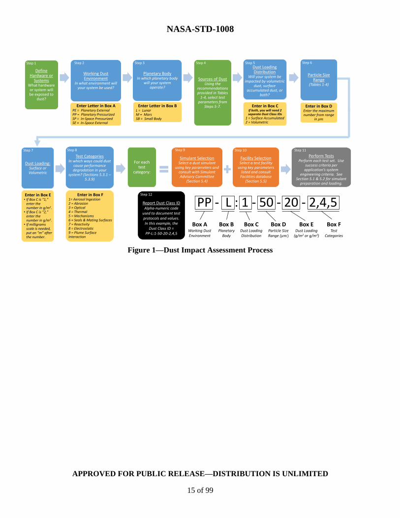
4.1 Dust Impact Assessment Process
The intention of the Dust Impact Assessment Process is that a user will adhere to this process to
identify a set of valid and repeatable test protocols to validate their hardware/system(s) for use
in a dust-laden environment. After completing the recommended testing, the user creates an
alpha-numeric code (i.e., Dust Class ID) to identify the protocol(s) to which they have
validated their hardware/system(s).
[DTR 1] Systems and hardware subjected to planetary dust shall be defined, classified, tested,
and documented in accordance with Figure 1, Dust Impact Assessment Process, and Table 1,
Dust Impact Assessment Process Steps.
NASA-STD-1008
APPROVED FOR PUBLIC RELEASE—DISTRIBUTION IS UNLIMITED
15 of 99
Figure 1—Dust Impact Assessment Process
Test CategoriesIn which ways could dust
cause performance degradation in your
system? (Sections 5.3.1 –5.3.9)
For each test
category:
Simulant SelectionSelect a dust simulant
using key parameters and consult with Simulant Advisory Committee
(Section 5.4)
Facility SelectionSelect a test facility
using key parameters listed and consult Facilities database
(Section 5.5)
Perform TestsPerform each test set. Use
success criteria per application’s system
engineering criteria. See Section 5.1 & 5.2 for simulant
preparation and loading.
Working Dust Environment
In what environment will your system be used?
Planetary BodyIn which planetary body
will your system operate?
Sources of DustUsing the
recommendations provided in Tables
1-4, select test parameters from
Steps 5-7.Enter Letter in Box APE = Planetary ExternalPP = Planetary PressurizedSP = In-Space Pressurized SE = In-Space External
Enter Letter in Box BL = LunarM = MarsSB = Small Body
Particle Size Range
(Tables 1-4)
Enter in Box DEnter the maximum number from range
in
Enter in Box E• If Box C is “1,”
enter the number in g/m2.
• If Box C is “2,” enter the number in g/m3.
• If milligrams scale is needed, put an “m” after the number.
Dust Loading Distribution
Will your system be impacted by volumetric
dust, surface accumulated dust, or
both?
Enter in Box CIf both, you will need 2 separate Dust Class IDs
1 = Surface Accumulated2 = Volumetric
Enter in Box F1= Aerosol Ingestion2 = Abrasion3 = Optical4 = Thermal 5 = Mechanisms6 = Seals & Mating Surfaces7 = Reactivity8 = Electrostatic9 = Plume Surface Interaction
PP - L : 1 - 50 - 20 - 2,4,5
Box CDust Loading Distribution
Box DParticle Size Range (
Box EDust Loading
(g/m2 or g/m3)
Box FTest
Categories
Box BPlanetary
Body
Box AWorking Dust Environment
Define Hardware or
SystemsWhat hardware or system will be exposed to
dust?
Step 1 Step 2 Step 3 Step 4 Step 5 Step 6
Step 8 Step 10 Step 11
Dust Loading: Surface or Volumetric
Step 7 Step 9
Report Dust Class IDAlpha-numeric code
used to document test protocols and values. In this example, the
Dust Class ID =PP-L:1-50-20-2,4,5
Step 12
NASA-STD-1008
APPROVED FOR PUBLIC RELEASE—DISTRIBUTION IS UNLIMITED
16 of 99
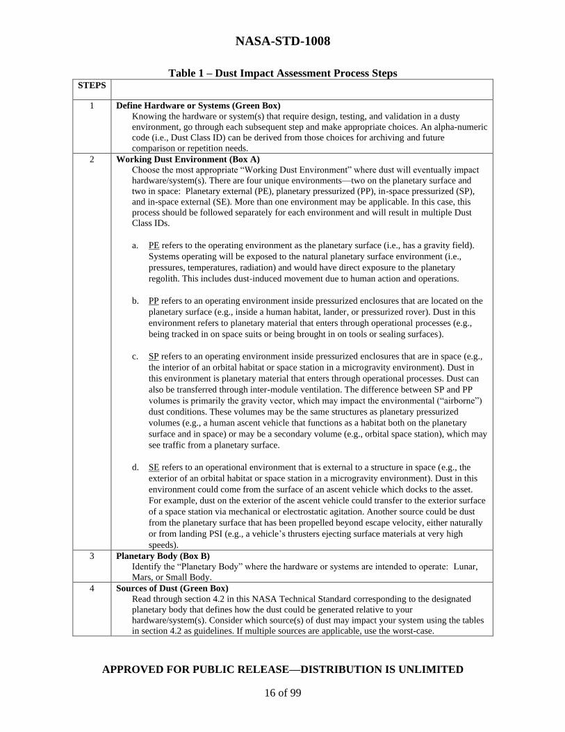
Table 1 – Dust Impact Assessment Process Steps STEPS
1 Define Hardware or Systems (Green Box)
Knowing the hardware or system(s) that require design, testing, and validation in a dusty
environment, go through each subsequent step and make appropriate choices. An alpha-numeric
code (i.e., Dust Class ID) can be derived from those choices for archiving and future
comparison or repetition needs.
2 Working Dust Environment (Box A)
Choose the most appropriate “Working Dust Environment” where dust will eventually impact
hardware/system(s). There are four unique environments—two on the planetary surface and
two in space: Planetary external (PE), planetary pressurized (PP), in-space pressurized (SP),
and in-space external (SE). More than one environment may be applicable. In this case, this
process should be followed separately for each environment and will result in multiple Dust
Class IDs.
a. PE refers to the operating environment as the planetary surface (i.e., has a gravity field).
Systems operating will be exposed to the natural planetary surface environment (i.e.,
pressures, temperatures, radiation) and would have direct exposure to the planetary
regolith. This includes dust-induced movement due to human action and operations.
b. PP refers to an operating environment inside pressurized enclosures that are located on the
planetary surface (e.g., inside a human habitat, lander, or pressurized rover). Dust in this
environment refers to planetary material that enters through operational processes (e.g.,
being tracked in on space suits or being brought in on tools or sealing surfaces).
c. SP refers to an operating environment inside pressurized enclosures that are in space (e.g.,
the interior of an orbital habitat or space station in a microgravity environment). Dust in
this environment is planetary material that enters through operational processes. Dust can
also be transferred through inter-module ventilation. The difference between SP and PP
volumes is primarily the gravity vector, which may impact the environmental (“airborne”)
dust conditions. These volumes may be the same structures as planetary pressurized
volumes (e.g., a human ascent vehicle that functions as a habitat both on the planetary
surface and in space) or may be a secondary volume (e.g., orbital space station), which may
see traffic from a planetary surface.
d. SE refers to an operational environment that is external to a structure in space (e.g., the
exterior of an orbital habitat or space station in a microgravity environment). Dust in this
environment could come from the surface of an ascent vehicle which docks to the asset.
For example, dust on the exterior of the ascent vehicle could transfer to the exterior surface
of a space station via mechanical or electrostatic agitation. Another source could be dust
from the planetary surface that has been propelled beyond escape velocity, either naturally
or from landing PSI (e.g., a vehicle’s thrusters ejecting surface materials at very high
speeds).
3 Planetary Body (Box B)
Identify the “Planetary Body” where the hardware or systems are intended to operate: Lunar,
Mars, or Small Body.
4 Sources of Dust (Green Box)
Read through section 4.2 in this NASA Technical Standard corresponding to the designated
planetary body that defines how the dust could be generated relative to your
hardware/system(s). Consider which source(s) of dust may impact your system using the tables
in section 4.2 as guidelines. If multiple sources are applicable, use the worst-case.

NASA-STD-1008
APPROVED FOR PUBLIC RELEASE—DISTRIBUTION IS UNLIMITED
17 of 99
5 Dust Loading Distribution (Box C)
Choose the expected “Dust Loading Distribution,” surface accumulated or volumetric. In the
tables in section 4.2 of this NASA Technical Standard, recommendations are given as to the
dust exposure levels that may result. These recommendations should be used to select which
dust characteristics and parameters to use for testing. This box is closely tied to Box E.
a. Surface Accumulated Loading: Defines quantities of dust that may accumulate on
exposed surfaces or that might be mechanically ingrained in surface materials.
Accumulation would be dependent on the dust source, time of exposure, and distance
from the dust source. Instead of reproducing these conditions in a test environment and
allowing dust to settle and accumulate, the system can be coated with the appropriate
mass of dust prior to the test. The amount of dust accumulating in any environment
should be taken as the worst-case loading. Optimization is based on assumptions for
ranges of primary or expected interest (i.e., a priori requirements, measurements, or
modeled conditions, as will be expected during dust particle movement and settling).
Users should consider what surfaces of their hardware/system(s) will be exposed to and
impacted by dust accumulation. These numbers define the full accumulation over a
specified interval on that surface upon exposure, thus encompassing adhesion effects.
The surface area (m2) is the surface area of the hardware where dust is being deposited.
The mass (g) is the amount of dust being deposited onto the surface area.
b. Volumetric Loading: The amount of dust that is held/placed in suspension in a given
environment will be impacted by pressure and gravity levels. Volumetric loading refers
to dust that is aloft and is defined in terms of mass per unit volume. For indoor spaces,
this is also referred to as aerosol mass concentration. While this would ultimately
impact surface accumulation through gravitational settling, this volumetric loading is
meant for hardware/system(s) that are directly impacted by actively aloft dust, like
systems that could ingest particulate matter from the environment (e.g., fans) or optical
systems where lofted dust may cause interference or light dispersion. In the Test
Categories (Step 8), volumetric loading primarily impacts the Aerosol Ingestion Testing
section (section 5.3.1 of this NASA Technical Standard). Not all lofted dust in an
atmosphere is considered an aerosol; for example, dust lofted in the tenuous lunar
exosphere is not considered an aerosol, by definition. Categories are optimized based on
assumptions for ranges of primary or expected interest (i.e., a priori requirements,
measurements, or modeled conditions, as will be expected during dust particle
movement and settling).
6 Particle Size Range (Box D)
Choose the appropriate “Particle Size Range” expected to affect your hardware/system(s) based
on the recommendations for each of the sources of dust in section 4.2 of this NASA Technical
Standard that might impact/affect the hardware/system(s). For identification, use only the
maximum expected particle size of the chosen range for the Dust Class ID notation value. The
definition of “dust” in this NASA Technical Standard is the maximum particle size(s) that will
likely cause the most concern for a particular system. Box D is where that particle size is noted.
Based on the sources of dust that will impact the system, select the number associated with the
largest range for use in testing. Ranges are defined as all particulate matter below a certain size.
For cases where particles smaller than a given size are not necessary for testing, those smaller-
sized fractions can be removed (see section 5.1.1 of this NASA Technical Standard). The unit
micrometer (µm) is used to define dust sizes in this NASA Technical Standard.
7 Dust Loading (Box E)
Calculate the expected worst-case “Dust Loading” value based on the recommendations for
each of the tables in section 4.2 of this NASA Technical Standard that impacts the
hardware/system(s). This section is closely tied to Box C and should be referenced in parallel. It
is used to describe a value or range of values, both volumetric and area, that can be applied to
hardware/system(s) conditions and testing as needed. This designation will define the units of
NASA-STD-1008
APPROVED FOR PUBLIC RELEASE—DISTRIBUTION IS UNLIMITED
18 of 99
measure for testing. For surface accumulated dust loading, the unit will be g/m2. For volumetric
dust loading distributions, the unit will be g/m3.
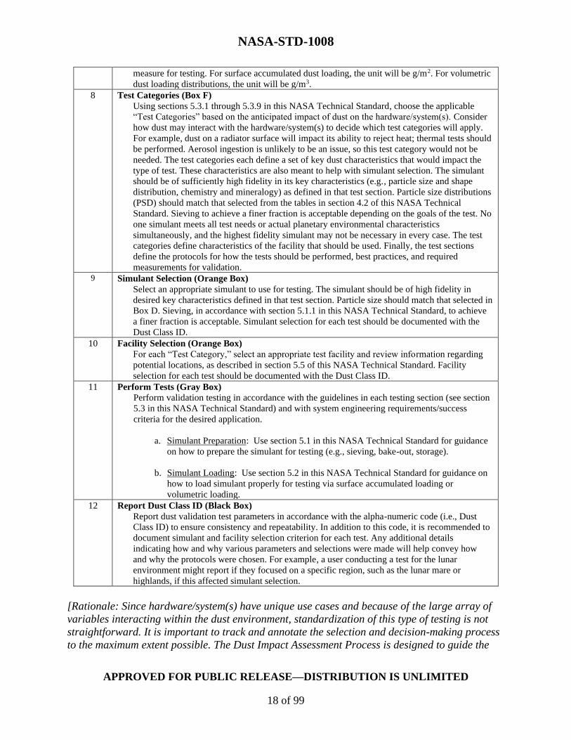
8 Test Categories (Box F)
Using sections 5.3.1 through 5.3.9 in this NASA Technical Standard, choose the applicable
“Test Categories” based on the anticipated impact of dust on the hardware/system(s). Consider
how dust may interact with the hardware/system(s) to decide which test categories will apply.
For example, dust on a radiator surface will impact its ability to reject heat; thermal tests should
be performed. Aerosol ingestion is unlikely to be an issue, so this test category would not be
needed. The test categories each define a set of key dust characteristics that would impact the
type of test. These characteristics are also meant to help with simulant selection. The simulant
should be of sufficiently high fidelity in its key characteristics (e.g., particle size and shape
distribution, chemistry and mineralogy) as defined in that test section. Particle size distributions
(PSD) should match that selected from the tables in section 4.2 of this NASA Technical
Standard. Sieving to achieve a finer fraction is acceptable depending on the goals of the test. No
one simulant meets all test needs or actual planetary environmental characteristics
simultaneously, and the highest fidelity simulant may not be necessary in every case. The test
categories define characteristics of the facility that should be used. Finally, the test sections
define the protocols for how the tests should be performed, best practices, and required
measurements for validation. 9 Simulant Selection (Orange Box)
Select an appropriate simulant to use for testing. The simulant should be of high fidelity in
desired key characteristics defined in that test section. Particle size should match that selected in
Box D. Sieving, in accordance with section 5.1.1 in this NASA Technical Standard, to achieve
a finer fraction is acceptable. Simulant selection for each test should be documented with the
Dust Class ID.
10 Facility Selection (Orange Box)
For each “Test Category,” select an appropriate test facility and review information regarding
potential locations, as described in section 5.5 of this NASA Technical Standard. Facility
selection for each test should be documented with the Dust Class ID.
11 Perform Tests (Gray Box)
Perform validation testing in accordance with the guidelines in each testing section (see section
5.3 in this NASA Technical Standard) and with system engineering requirements/success
criteria for the desired application.
a. Simulant Preparation: Use section 5.1 in this NASA Technical Standard for guidance
on how to prepare the simulant for testing (e.g., sieving, bake-out, storage).
b. Simulant Loading: Use section 5.2 in this NASA Technical Standard for guidance on
how to load simulant properly for testing via surface accumulated loading or
volumetric loading.
12 Report Dust Class ID (Black Box)
Report dust validation test parameters in accordance with the alpha-numeric code (i.e., Dust
Class ID) to ensure consistency and repeatability. In addition to this code, it is recommended to
document simulant and facility selection criterion for each test. Any additional details
indicating how and why various parameters and selections were made will help convey how
and why the protocols were chosen. For example, a user conducting a test for the lunar
environment might report if they focused on a specific region, such as the lunar mare or
highlands, if this affected simulant selection.
[Rationale: Since hardware/system(s) have unique use cases and because of the large array of
variables interacting within the dust environment, standardization of this type of testing is not
straightforward. It is important to track and annotate the selection and decision-making process
to the maximum extent possible. The Dust Impact Assessment Process is designed to guide the

NASA-STD-1008
APPROVED FOR PUBLIC RELEASE—DISTRIBUTION IS UNLIMITED
19 of 99
decision-making process, providing a standardized means of determining the appropriate test
protocols, simulant characteristics, and facility capabilities for the testing of systems and
hardware that interact within dusty planetary environments. The Dust Impact Assessment
Process indicates how to fill in the alpha-numeric code (i.e., Dust Class ID) that will be used to
define the appropriate test conditions. This code can then be used to report the protocol(s)
followed in testing the hardware/system(s). Documentation of the simulant and facility selections
is expected to consist of a description of the simulant and facility chosen and the rationale for
the use of that simulant and facility in the NASA-STD-1008 compliance assessment.]
Appendix B provides examples to demonstrate how to follow the Dust Impact Assessment
Process to determine the necessary test protocol(s) and resulting Dust Class ID.
4.2 Sources of Dust
It is necessary to understand and define the surface and dust environments in which hardware
will be exposed to planetary environmental dust, as these parameters can affect system and
hardware performance, sustainability, and crew safety.
This section revolves around four specific locations (i.e., working dust environments) where dust
may be a factor. For each working dust environment, sources of dust are described, as well as
environment-specific parameters. The four working dust environments are PE, PP, SP, and SE.
The terms “planetary” and “in-space” refer to surface and off-surface environments,
respectively. In addition, the terms “pressurized” and “external” refer to environments inside or
outside of pressurized volumes, respectively.
In the case of the Moon, two potentially unique dusty environment examples regarding potential
interactions and impacts on external orbital operations and hardware are due to the presence of
a tenuous lunar exosphere, created partly by meteorite impact ejecta thrown off the planetary
surfaces. Additionally, a certain amount of lunar dust may be transferred to lunar orbit through
rocket engine-surface plume interactions or carried to orbit on the surfaces of orbital return
vehicles.
In the case of Mars, additional considerations will be employed due to a planetary atmosphere
and the existence of dust storms.
In the case of small bodies, only two cases will exist similar to the orbital classifications, except
in cases where the gravity field is significant.
a. Planetary External (PE)
This section defines the dusty environment requirements and classifications for
external surfaces and hardware operating on a planetary surface.
NASA-STD-1008
APPROVED FOR PUBLIC RELEASE—DISTRIBUTION IS UNLIMITED
20 of 99
(1) Lunar Sources of Dust
Evaluate the values in Table 2, Planetary External Lunar Sources of Dust and
Associated Dust Parameters, to ensure they are appropriate for the hardware or
system being tested and document justification for using different values along
with the Dust Class ID.

NASA-STD-1008
APPROVED FOR PUBLIC RELEASE—DISTRIBUTION IS UNLIMITED
21 of 99
Table 2—Planetary External Lunar Sources of Dust and Associated Dust Parameters
PE Lunar Sources of
Dust
Particle
Size
(µm)
Surface
Accumulated
Loading (g/m2)
Volumetric
Loading (g/m3)
Dust
Velocity
(m/s)
Charge to Mass Ratio
(nC/g)
Human-Generated
Surface Transported
Dust
<500 µm [1] <40 g/m2 [TBR][11] N/A <10 m/s
(22.4
mph) [2]
0.1 nC/g - 10 nC/g [15]
Rocket Engine Plume
Dust [9, 13]
<10,000 µm [3][12][20]
TBR [21] 108 - 1013
particles/m3
[4][15] [20]
<4500
m/s
(10,066
mph) [13]
>1000 nC/g
Natural Charged Dust
Transport [5]
<1000 µm [16] Combined Loading
Case [17, 19]
TBR [6] Variable [18]
~ 10,000 nC/g [7]
Natural Impact Ejecta [12]
<10,000 µm Combined Loading
Case [17, 19] or 0.01
g/m2/day [14]
TBR [10] <2380
m/s
(5324
mph) [8]
~ 10,000 nC/g [7]
Notes: 1. Estimated maximum particle size displaced by Apollo lunar rover.
2. Reference NASA-CR-4404, Lunar dust transport and potential interactions with power system components. The Apollo lunar rovers
were designed to travel at a maximum of 3.56 m/s (8 mph) (reference Backer, 1971; Hsu and Horanyi, 2012) with particle speeds of up
to 7.12 m/s (16 mph) in the forward direction. A 45° trajectory would yield the maximum horizontal distance of 31 m (103 ft) from the
wheel's initial location. Consider the maximum speed at which an Artemis Lunar Terrain Vehicle could travel.
3. Reference Lane, et al., 2008; Morris, et al., 2015.
4. Reference Immer, et al., 2011a. Analysis of digitized Apollo Lunar Module (LM) descent videos estimates plume lofted dust sheets
contained 108-1013 particles/m3 and were blown radially away from the descent engine at angles of 0-3° above the surface. Volumetric
loading as a mass density should be determined by the user based on their choice of simulant.
5. Reference Colwell, et al., 2009.
6. Charged dust transport on the lunar surface is an area of ongoing research, and dust loading has not been quantified in situ.
7. Reference Colwell, et al., 2007.
8. The finest particles are ejected at velocities exceeding the 2.38 km/s (5324 mph) escape velocity of the Moon (see section 5.1.1 of this
NASA Technical Standard).
NASA-STD-1008
APPROVED FOR PUBLIC RELEASE—DISTRIBUTION IS UNLIMITED
22 of 99
9. The effects of rocket engine exhaust on a planetary body are a subject of ongoing research. Values in this section are estimates. Dust
may theoretically be accelerated up to the velocity of the rocket exhaust but is likely slower. Actual dust velocities will depend on
regolith properties and the exhaust flow field. On average, there is an inverse relationship between particle size and particle velocity.
Particles larger than 1 cm may be moved or lofted, but the effects of large particle impacts are outside the scope of this NASA Technical
Standard. See section 4.2, Table 5, In-Space External Lunar Sources of Dust and Associated Dust Parameters, Note 5 in this NASA
Technical Standard for additional considerations.
10. Loading due to impact ejecta is sparse. Model development is underway (see Note 14) to quantify this type of loading at the surface.
Since impact ejecta is lofted at a relatively high angle, impacts to surface assets from particles on escape trajectories are unlikely.
11. Maximum estimated dust movement observed in Apollo walking and rover video archives.
12. Rocks as large as 10 cm or more can be moved, while dust- to sand-size particles in the upper few cm of regolith in the area surrounding
the LM were blown several kilometers away, leaving the coarser, presumably more compact, underlying regolith exposed (reference
Immer, et al., 2008; Lane, et al., 2008; Metzger, et al., 2011).
13. Exhaust velocity of a liquid oxygen/liquid hydrogen (LOX/LH2) engine. May be treated as an example maximum. See Note 9.
14. Estimated from NASA-SP-8013, Meteoroid Environmental Model. Updated model is under development which will be available in a
future revision of SLS-SPEC-159H, Cross-Program Design Specification for Natural Environments (DSNE), section 3.4.8.2.
15. Reference Jackson, et al., 2011, 2015.
16. Colwell, et al., 2007 notes the historical distinction between soil particles (<1 cm diameter), fines (<1 mm), and dust (< 100 µm); and the paper considers phenomena on particles <1 cm in size. Suggested upper bound is set by pragmatic concerns but
may be altered by the user as needed.
17. Combined natural calculated to be 1.0 g/m2/year (Hollick and O’Brien, 2013).
18. Lofted dust vertical velocities will depend on individual particle size, density, and location in ballistic trajectory in the lunar gravity
field.
19. Few individual measurements have been made of the two natural distribution cases, but combined cases exist (Li, et al., 2019) where the
value of 6.5 × 10⁻⁶ g/m2 were seen at the Chang’E-3 landing site.
20. Planned hot-fire ground tests and modeling efforts will provide ejecta PSD and bulk density (volumetric loading) parameters. These
science-scale and human-scale lander tests are planned for mid-FY22 and mid-FY24.
21. Future PSI investigations could provide test data using characterized coupons to help address the gap of surface accumulated loading
from rocket engine plume dust.

NASA-STD-1008
APPROVED FOR PUBLIC RELEASE—DISTRIBUTION IS UNLIMITED
23 of 99
Table 2 describes potential lunar sources of dust generation and the associated
characteristics, including particle size, surface accumulated loading, volumetric loading,
dust velocity, and charge-to-mass ratio. Determine which sources of dust generation are
applicable. The quantities given are provided to select the appropriate maximum particle
size and dust loading for testing. Where possible, a single maximum number is provided
assuming all lower values are included in any testing or assessments.
These values may change as knowledge of the environment grows and as the surface
architecture evolves. The current values reflect existing experience with lunar activities,
operations, and hardware and subsequent research. This NASA Technical Standard will
be updated to reflect future discoveries or surface architectures that may alter the values
or sources of dust.
Dust velocities may be unique to certain environments (is unique to certain environments
and not referred to in the Dust Impact Assessment Process flow chart (see Figure 1 and
Table 1).
Lunar dust is mobilized from human activities on the lunar surface and by the natural,
highly variable, permanently present dusty exosphere. Transported dust will settle and
require systems and hardware on the surface to be tolerant to such contamination.
Systems and hardware that will be moved between the surface and pressurized habitable
volumes may require remediation to reduce dust to acceptable and safe levels.
(2) Martian Sources of Dust
Reserved.
(3) Small Bodies Sources of Dust
Reserved.
b. Planetary Pressurized (PP)
This section defines the dusty environment requirements and classifications for
hardware operating in an environment inside pressurized enclosures that are located
on the planetary surface.
(1) Lunar Sources of Dust
Evaluate the values listed in Table 3, Planetary Pressurized Lunar Sources of
Dust and Associated Dust Parameters, to ensure they are appropriate for the
hardware or system being tested and document justification for using different
values, along with the Dust Class ID.

NASA-STD-1008
APPROVED FOR PUBLIC RELEASE—DISTRIBUTION IS UNLIMITED
24 of 99
Table 3—Planetary Pressurized Lunar Sources of Dust and Associated Dust Parameters
PP Lunar Sources of
Dust
Particle Size
(µm)
Surface
Accumulated
Loading (g/m2)
Volumetric
Loading (g/m3)
Dust
Velocity
(m/s)
Charge to
Mass Ratio
(nC/g)
Extravehicular
Activity (EVA) Suit
Cross-Hatch
Transported Dust
<500 µm [TBR] [1]
50 g per suit per
EVA[2][3][5]
10 g/m3 per suit
per EVA [2][3][4]
Variable [6] N/A
Hardware Cross-
Hatch Transported
Dust
<500 µm [TBR] [1]
Variable g/m2 [2] Variable g/m3 [2] Variable [6] N/A
Notes:
1. Apollo 17 suit maximum particle size (NASA/TP-2009-214786). This value may change with new suit
materials and/or designs.
2. These values may vary depending on program requirements. In some cases, the requirement for EVA suit cross-
hatch transported dust and hardware cross-hatch transported dust may be combined.
3. Assuming 50 g of dust per crewmember per EVA based on EVA to Human Landing System (HLS)
requirements.
4. Assuming dust concentration is 50 g spread evenly throughout 5 m3 habitable volume. Value can be adjusted for
different dust concentrations and habitable volumes. Assuming all dust on suit becomes airborne in habitable
space, the concentration of airborne lunar dust would be 10 g/m3 per suit per EVA. It is expected that post EVA
remediation efforts will reduce the transferred dust loading on each individual EVA, but that a net buildup over
multiple EVAs will occur.
5. This cell contains a mass rather than surface loading, which should be converted to an areal mass density before
use in the Dust Class ID. This cell may be interpreted by: (1) dividing the dust mass by the surface area of the
EVA suit, if suit loading is desired; or (2) dividing the mass by the affected interior surface area.
6. Aerosol particles travel with the same velocity as free airflow (in cabin or ducting). Particles impact onto
surfaces at interruptions to free flow (e.g., sharp bends in the airstream).
Operational transport of dust inside the pressurized volume has the potential to
damage and degrade the performance of system elements (e.g., hatch seals, the
environmental control and life support system (ECLSS), and various sensitive
surfaces) and affect human health and performance. (For human environmental dust
limits, refer to NASA-STD-3001 Volume 2).
Table 3 describes potential lunar sources of dust generation and the associated
characteristics, including particle size, surface accumulated loading, volumetric
loading, dust velocity, and charge-to-mass ratio. Determine which sources of dust
generation are applicable. The quantities given are intended as guidelines to select
the appropriate maximum particle size and dust loading for testing. Where possible, a
single maximum number is provided assuming all lower values are included in any
testing or assessments. These values may change as knowledge of the environment
grows.
Dust particles smaller than roughly 50 µm are invisible to the average unaided eye.
Dust location and accumulation will depend on its ability to adhere to materials
within pressurized habitable volumes. Dust may also accumulate in cracks and

NASA-STD-1008
APPROVED FOR PUBLIC RELEASE—DISTRIBUTION IS UNLIMITED
25 of 99
crevices where tools cannot reach, likely due to adhesive and cohesive forces, surface
material characteristics, and cabin design.
Note: Pressurized volumes can be habitable or not. It would be expected that
habitable volumes would have more stringent requirements for lunar dust
contamination as a crew health concern. Understanding if the hardware will be in a
pressurized volume versus a habitable volume may impact the loading conditions of a
planned test. Users should determine if a Health and Medical requirement defines a
governing dust loading limitation, which could drive planned test conditions.
(2) Martian Sources of Dust
Reserved.
(3) Small Bodies Sources of Dust
Reserved.
c. In-Space Pressurized (SP)
This section defines the dusty environment requirements and classifications for
hardware operating in an environment inside pressurized enclosures that are in
space.
(1) Lunar Sources of Dust
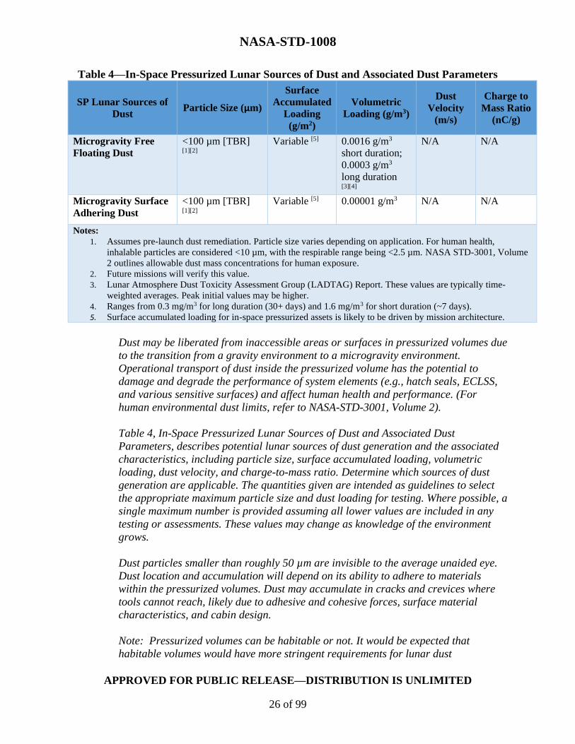
Evaluate the values listed in Table 4, In-Space Pressurized Lunar Sources of Dust
and Associated Dust Parameters, to ensure they are appropriate for the hardware
or system being tested and document justification for using different values, along
with the Dust Class ID.
NASA-STD-1008
APPROVED FOR PUBLIC RELEASE—DISTRIBUTION IS UNLIMITED
26 of 99
Table 4—In-Space Pressurized Lunar Sources of Dust and Associated Dust Parameters
SP Lunar Sources of
Dust Particle Size (µm)
Surface
Accumulated
Loading
(g/m2)
Volumetric
Loading (g/m3)
Dust
Velocity
(m/s)
Charge to
Mass Ratio
(nC/g)
Microgravity Free
Floating Dust
<100 µm [TBR] [1][2]
Variable [5] 0.0016 g/m3
short duration;
0.0003 g/m3
long duration [3][4]
N/A N/A
Microgravity Surface
Adhering Dust
<100 µm [TBR] [1][2]
Variable [5] 0.00001 g/m3 N/A N/A
Notes:
1. Assumes pre-launch dust remediation. Particle size varies depending on application. For human health,
inhalable particles are considered <10 µm, with the respirable range being <2.5 µm. NASA STD-3001, Volume
2 outlines allowable dust mass concentrations for human exposure.
2. Future missions will verify this value.
3. Lunar Atmosphere Dust Toxicity Assessment Group (LADTAG) Report. These values are typically time-
weighted averages. Peak initial values may be higher.
4. Ranges from 0.3 mg/m3 for long duration (30+ days) and 1.6 mg/m3 for short duration (~7 days).
5. Surface accumulated loading for in-space pressurized assets is likely to be driven by mission architecture.
Dust may be liberated from inaccessible areas or surfaces in pressurized volumes due
to the transition from a gravity environment to a microgravity environment.
Operational transport of dust inside the pressurized volume has the potential to
damage and degrade the performance of system elements (e.g., hatch seals, ECLSS,
and various sensitive surfaces) and affect human health and performance. (For
human environmental dust limits, refer to NASA-STD-3001, Volume 2).
Table 4, In-Space Pressurized Lunar Sources of Dust and Associated Dust
Parameters, describes potential lunar sources of dust generation and the associated
characteristics, including particle size, surface accumulated loading, volumetric
loading, dust velocity, and charge-to-mass ratio. Determine which sources of dust
generation are applicable. The quantities given are intended as guidelines to select
the appropriate maximum particle size and dust loading for testing. Where possible, a
single maximum number is provided assuming all lower values are included in any
testing or assessments. These values may change as knowledge of the environment
grows.
Dust particles smaller than roughly 50 µm are invisible to the average unaided eye.
Dust location and accumulation will depend on its ability to adhere to materials
within the pressurized volumes. Dust may accumulate in cracks and crevices where
tools cannot reach, likely due to adhesive and cohesive forces, surface material
characteristics, and cabin design.
Note: Pressurized volumes can be habitable or not. It would be expected that
habitable volumes would have more stringent requirements for lunar dust

NASA-STD-1008
APPROVED FOR PUBLIC RELEASE—DISTRIBUTION IS UNLIMITED
27 of 99
contamination as a crew health concern. Understanding if the hardware will be in a
pressurized volume versus a habitable volume may impact the loading conditions of a
planned test.
(2) Martian Sources of Dust
Reserved.
(3) Small Bodies Sources of Dust
Reserved.
d. In-Space External (SE)
This section defines the dusty environment requirements and classifications for
surfaces and hardware operating in an environment that is external to a structural in
space.
(1) Lunar Sources of Dust
Evaluate the values listed in Table 5, In-Space External Lunar Sources of Dust
and Associated Dust Parameters, to ensure they are appropriate for the hardware
or system being tested and document justification for using different values, along
with the Dust Class ID.

NASA-STD-1008
APPROVED FOR PUBLIC RELEASE—DISTRIBUTION IS UNLIMITED
28 of 99
Table 5—In-Space External Lunar Sources of Dust and Associated Dust Parameters
SE Lunar Sources of Dust Particle Size
(µm)
Surface
Accumulated
Loading
(g/m2)
Volumetric
Loading (g/m3)
Dust
Velocity
(m/s)
Charge-to-
Mass Ratio
(nC/g)
Rocket Plume Dust [4] TBR [8] TBR [8] TBR [8] <4500 m/s
(10,066
mph) [5]
>1000 nC/g
Natural Impact Dust
Transport
(Surface Ejecta)
<10 µm [1] Variable [7] <10-2 particles /
m3 [3]
10 m/s-
1000 m/s
(22.4 mph-
2240 mph)
N/A
Surface Returned Vehicle
Transported Dust [9]
<100 µm 40 g/m2 [9] TBR [9] TBR [9] TBR [9]
Notes:
1. The on-orbit lunar dust environment has been measured between 3 km (1.86 mi) and 250 km (155 mi) altitude.
This NASA Technical Standard does not distinguish between natural particle sources but states the approximate
measured upper bound on particle size. See SLS-SPEC-159H, sections 3.4.2.2.3.2 - 3.4.2.2.3.4, for more details
on the lofted dust environment on orbit.
2. Reference Colwell, et al., 2007.
3. Non-standard units should be converted to a volumetric loading based on the PSD selected by the
program/project. See SLS-SPEC-159H, sections 3.4.2.2.3.2 - 3.4.2.2.3.4, for more details on the ejected dust
environment on orbit.
4. Analysis of digitized Apollo LM descent videos estimated plume-lofted dust sheets contained 108-1013
particles/m3 and were blown radially away from the descent engines at angles of 0-3° relative to the surface
(reference Immer, et al., 2011a). The finest particles are blown at velocities reaching up to 3 km/s (6711 mph),
exceeding the 2.38 km/s (5324 mph) escape velocity of the Moon (reference Lane, et al., 2008; Metzger, et al.,
2011).
5. The effects of plume-surface interactions are areas of ongoing research. Dust ejected from a rocket landing may
theoretically accelerate up to the exhaust gas velocity. This example velocity is taken from a liquid
oxygen/liquid hydrogen (LOX/LH2) engine. Actual dust velocities will depend significantly on architecture and
concepts of operation. Dust will be more dispersed at higher altitudes. On average, there is an inverse
relationship between particle size and particle velocity. See section 4.2, Table 2, Planetary External Lunar
Sources of Dust and Associated Dust Parameters, Notes 9 and 13 in this NASA Technical Standard, for
additional justification and considerations.
6. Lofted dust vertical velocities will depend on individual particle size, density, and location in ballistic trajectory
in the lunar gravity field.
7. Depends on amount of supplied dust, flight path, and adhesive materials properties of surface of deposition.
8. Future PSI investigations or modeling could provide data to help quantify expected particle size, surface
accumulated loading, and volumetric loading from rocket engine plume dust.
9. This represents dust transferred from a mating visiting vehicle from a surface excursion. The mating can be
from docking or berthing. At the time of this writing, little is known about the transfer of dust from a surface
lander to an orbiting platform. Future modeling will constrain expected particle size, surface accumulated
loading, and volumetric loading from vehicle transported dust.
Operational transport of dust has the potential to damage and degrade the
performance of system elements (e.g., docking ring seals and sensitive surfaces).
NASA-STD-1008
APPROVED FOR PUBLIC RELEASE—DISTRIBUTION IS UNLIMITED
29 of 99
Table 5 describes potential lunar sources of dust generation and the associated
characteristics, including particle size, surface-accumulated loading, volumetric
loading, dust velocity, and charge-to-mass ratio. Users will determine which sources
of dust generation are applicable. The quantities given are intended as guidelines to
select the appropriate maximum particle size and dust loading for testing. Where
possible, a single maximum number is provided assuming all lower values are also
included in any testing or assessments. These values may change as knowledge of the
environment grows.
There are two primary sources of dust for an orbiting vehicle. The first is dust
transferred from a mating visiting vehicle from a surface excursion. This could be
from a human lander or a robotic sample return vehicle. The mating can be from
docking or berthing. The second source is dust ejected from the surface through
plume-surface interactions or meteor impacts. Plume-surface interactions transfer
dust from the surface to some altitudes when a surface vehicle lands and/or lifts-off.
Meteor impacts to the surface can result in dust being lofted from the surface. The
dust lofted from meteor impacts is described in SLS-SPEC-159H.
(2) Martian Sources of Dust
Reserved.
(3) Small Bodies Sources of Dust
Reserved.
5. TESTING METHODOLOGIES AND BEST PRACTICES
This section provides requirements and guidelines for hardware/system(s) testing, including how
to prepare simulant for testing and how to load/distribute the simulant onto the
hardware/system(s). This section includes testing methodologies and best practices for several
different types of tests. For each type of test, recommended simulant characteristics and facility
capabilities are provided. The section concludes with information and guidelines on how to
select appropriate simulants and facilities that can be tailored to user needs. Appendix A
provides context for why it is necessary to test and examine the effects of dust on hardware and
systems.
Note: This NASA Technical Standard does not provide pass/fail criteria or key performance
parameters (KPP) for each test type. Pass/fail criteria and KPPs are highly dependent upon
hardware/system(s) and will be specifically determined by user, programs, or projects.
Note: Examples of products identified in this NASA Technical Standard do not constitute
endorsement by NASA.
NASA-STD-1008
APPROVED FOR PUBLIC RELEASE—DISTRIBUTION IS UNLIMITED
30 of 99
5.1 Simulant Preparation and Storage
5.1.1 Particle Separation
[DTR 2] Systems and hardware shall be tested with simulants of appropriate particle size
distribution.
[Rationale: Simulants are typically offered to match the full particle size range of the planetary
material. To achieve the size fractions relevant to the particular test, particle separation may be
required. The assumption is that the appropriate fraction of the finest particles are present in
any batch of simulant and in any separated batch. Verification of the finest fraction (including
the nanometer scale ultra-fines; for a definition of the lunar regolith fine fraction, see SLS-
SPEC-159 DSNE, section 3.4.2.2.4) requires specialized instrumentation.]
If needed, the following methods can be used to modify the particle size distribution:
a. Sieve
Use sieving to allow particles to pass through progressively finer wire meshes (e.g., W.S. Tyler®
or equivalent) to separate various particle sizes, including the following standard sieving
processes:
[Rationale: Sieving of bulk simulant may be required to obtain the particle size ranges desired
for testing depending on user needs. Sieves should be visually inspected before each use for
clogs, tears, and residual particles. When sieves are clogged (>25% of surface area), clean
using approved methods (e.g., nylon brushes, ultrasonic cleaner, and/or compressed gas).]
(1) Dry Sieving
Use dry sieving to facilitate free-flowing dry particulate movement through the
specified sieve sizes via a vibrating, shaking, or tapping motion.
[Rationale: Mechanical sieve shaking equipment (e.g., Ro-Tap® or equivalent)
are commonly used to induce and standardize the vibrating, shaking, or tapping
motion. Dry sieving techniques are generally recommended for particle sizes >62
µm (i.e., mesh #250) (see USGS-OFR-2005-1230, Quality-assurance plan for the
analysis of fluvial sediment by the U.S. Geological Survey Kentucky Water
Science Center Sediment Laboratory).]
Note: ASTM C136/C136M-19, Standard Test Method for Sieve Analysis of Fine
and Coarse Aggregates, does not recommend dry sieving for particle sizes
<75 µm. ISO 17892-4:2016, Geotechnical investigation and testing – Laboratory
testing of soil – Part 4: Determination of particle size distribution, recommends
dry sieving for soils <125 mm with <10% fines. The exact threshold at which dry

NASA-STD-1008
APPROVED FOR PUBLIC RELEASE—DISTRIBUTION IS UNLIMITED
31 of 99
sieving versus wet sieving (see below) would be utilized varies depending on
particulate properties, equipment, environmental conditions, and technique.
Note: A relative humidity (RH)-controlled environment is recommended to reduce
clumping of finer particles when dry sieving. At high humidity moisture-induced
clumping may be an issue, while low humidity may result in electrostatic
clumping. Dry sieving at a relative humidity between 40-70% RH is
recommended.
Note: Dry sieving sub-millimeter simulants may cause mechanical irritation of
mucosal membranes and appropriate personal protective equipment (PPE)
should be used (e.g., respiratory and eye mask, gloves, vent hoods, and proper
ventilation). For simulants with chemistries that pose a silicosis risk, proper
handling and personal protection are mandatory.
Note: Vibration will inherently induce simulant sorting, affecting particle surface
interactions, orientation, and localized distribution. The significance of these
have to be established by observation.
(2) Wet Sieving
Use wet sieving to facilitate fine particle movement through specified sieve sizes
by leveraging solvents (e.g., denatured alcohol, deionized water) and gravity
flow.
[Rationale: Fine particles tend to clump together, adhere to larger particles, or
aerosolize making dry sieving fines problematic. Wet sieving techniques are
generally recommended for particles <62 µm (mesh No. 250) (reference USGS-
OFR-2005-1230).]
Note: ASTM C117-17, Standard Test Method for Materials Finer than 75-µm
(No. 200) Sieve in Mineral Aggregates by Washing, and ASTM D1140-17,
Standard Test Methods for Determining the Amount of Material Finer than 75-µm
(No. 200) Sieve in Soils by Washing, recommend wet sieving for particle sizes
<75 µm. ISO 17892-4 recommends wet sieving for soils <125 mm with >10%
fines. The exact threshold in which a user would utilize dry sieving or wet sieving
will vary depending on equipment, environmental conditions, and technique.
Note: Wet sieved simulants should follow section 5.1.1 in this NASA Technical
Standard to ensure the simulant is completely dry prior to storage or testing.
Note: In wet sieving, settling speeds are strongly affected by density, particle size,
and mass. This will cause physical sorting, especially with particles below
10 µm.

NASA-STD-1008
APPROVED FOR PUBLIC RELEASE—DISTRIBUTION IS UNLIMITED
32 of 99
Note: For almost all purposes, the mineralogy of lunar simulants, other than
those containing “volatiles,” are not negatively affected by immersion in water
for the time periods needed for wet sieving. Exposures to alcohols and other
organic liquids are also not considered a problem with respect to changes in
mineralogy. Mars simulants may contain hydrated minerals where impact of wet
sieving may need some additional consideration (TBD).
b. Cyclone Separation
Use cyclone separators to segregate simulant materials at sizes below those accommodated by
sieving.
[Rationale: Cyclone or vortex separation is based on the principal of establishing a balance
between inertial and aerodynamic drag forces. The latter is used to entrain particles in a
circulating rotational flow, wherein particles exceeding a critical size have sufficient momentum
to overcome their entrainment and deposit on the cyclone walls. Particle sizes below this limit
remain entrained in the exiting gas stream where they are subsequently collected or directly
dispersed. The technology for separators of this type is well developed, such that their
performance can be accurately modeled and constructed.]
Commercial off-the-shelf (COTS) versions of these devices are available from a variety of
manufacturers and can be tailored to individualized specifications. The particle cutoff diameter
is largely influenced by the operating parameters (e.g., input pressure and flow conditions). This
can be a benefit in terms of providing flexibility in adjusting the associated cutoff diameter, but
the user should recognize the need to control these parameters to achieve the targeted
performance and repeatability. Segregating particles below roughly 1 µm involves a more
complicated configuration. Since particle mass scales with diameter cubed, decreasing inertial
forces eventually result in the inability to overcome entrainment forces, requiring operation at
reduced pressures. In this fashion, cyclones have been demonstrated for sizes in the range of tens
of nanometers. Multi-stage devices have been developed, allowing the input material to be
segregated into a series of sequential size bins. A five-stage device of this type was developed
and used by NASA for the separation of lunar simulants. A related method is the virtual
impactor. However, for this technique, the cutoff diameter is not as sharply defined, and the
particle size ranges of the two exiting sample streams have overlap.
It is important to measure and confirm the size distribution of the separated material with an
appropriate aerosol instrument. In situations where the objective concerns surface deposition, it
should be noted that particles in this size range have insufficient mass to allow the loading to be
measured on a mass basis. Further, since the diffraction limited resolution of visible microscopy
is on the order of 0.2 µm, resolving particle sizes below this limit requires alternative methods
for surface analysis.
NASA-STD-1008
APPROVED FOR PUBLIC RELEASE—DISTRIBUTION IS UNLIMITED
33 of 99
c. Other Means of Particle Separation
Validate that the chosen separation method appropriately produces the desired simulant particle
distributions for a particular test.
Sieving and cyclone separation are common methods for simulant particle separation but are not
the only methods that are available for users. For example, impactors can remove dust particles
larger than the designed cutoff diameter; staged impactors with varying cutoff diameters can
further constrain the particle size. Monodisperse dust aerosol can be generated using a
differential mobility analyzer.
5.1.2 Bake-out
[DTR 3] Systems and hardware shall be tested with simulants that have been processed with
bake-out techniques in accordance with the following:
[Rationale: RH should be controlled (i.e., limited) to the extent practical to maximize the test
fidelity. However, the sensitivity of given test to humidity level is largely unknown. While bake-
out (i.e., drying) methodologies are offered, when possible it is recommended to run a few tests
with highly controlled humidity levels to gauge the impact on the results.]
These three water content sources and their impacts to testing are discussed in the following
paragraphs a., b., and c:
a. Physically Adsorbed Water
(1) Lunar Simulant
Heat the simulant at 110ºC (230ºF) for at least 12 hours.
[Rationale: Physically adsorbed, or physi-adsorbed, water is loosely bound to
the surface of the simulant. It is highly desirable that adsorbed water be
minimized for all tests. While this type of adsorbed water is easier to release, it
also will re-adsorb readily. It is difficult to control in ambient laboratory
environments as the simulant will re-adsorb water from the atmosphere within
minutes to hours (depending on exposure conditions [e.g., granular surface
area]). In some cases, the time scales of test preparation will defeat the effort
spent to bake-out to fully dry (i.e., 0 weight percent [wt%]) conditions. Most lunar
simulants will hold <0.5 wt% water in an ambient laboratory environment. This
“laboratory-stable” condition is likely to be sufficient for most tests, though this
has not been verified. Refer to ASTM D2216, Standard Test Methods for
Laboratory Determination of Water (Moisture) Content of Soil and Rock by
Mass.]

NASA-STD-1008
APPROVED FOR PUBLIC RELEASE—DISTRIBUTION IS UNLIMITED
34 of 99
Note 1: Simulants are generally poor thermal conductors. Therefore,
placing the simulant directly on a heat source (e.g., hot plate) and/or
heating too quickly may cause local hot spots and alteration of the
material. Mixing/stirring to improve heat transfer or using convective
heating (e.g., oven) is recommended to minimize this risk.
Note 2: The mean free path length in the simulant is very short due to the
abundance of small particles. Drying times will be much longer than for coarser
grained materials such as sand. Moisture levels can be tested using ASTM D2216
or a calibrated moisture balance at 110°C (230ºF). A minimum of three simulant
samples should be drawn from various spatial points and depths in the simulant
batch and then averaged to determine the bulk batch moisture content.
(2) Martian Simulant
Reserved
(3) Small Bodies Simulant
Reserved
b. Surface-Bound Water
(1) Lunar Simulant
Heat the simulant at 200°C (392°F) for 24 hours to release the surface-
bound water; after this, keep it hermetically sealed as practical or re-bake
before using.
Note 1: Simulants are generally poor thermal conductors. Therefore,
placing the simulant directly on a heat source (e.g., hot plate) and/or
heating too quickly may cause local hot spots and alteration of the
material. Mixing/stirring to improve heat transfer or using convective
heating (e.g., oven) is recommended to minimize this risk.
Note 2: One indication of moisture adsorption after drying is the use of
chemically treated desiccant material that changes color (e.g., from
dry/blue to pink/wet as the material is exposed to moisture. Containing the
desiccant in a fiber pouch is necessary to avoid simulant contamination.
[Rationale: Surface-bound water (H2O) is chemically bound to the simulant
surface and is more likely to impact the more chemistry-sensitive tests (e.g.,
electrical and reactivity tests and during tests in vacuum [see section 5.1.2c]) but
is less likely to impact the mechanical tests (e.g., abrasion, mechanisms). Surface-
bound water is chemically bound to mineral grain surfaces of the simulant and is

NASA-STD-1008
APPROVED FOR PUBLIC RELEASE—DISTRIBUTION IS UNLIMITED
35 of 99
generally not considered as “water” since the molecular structure orientation
differs. The energy of release of the water is higher than the physically adsorbed
water. This H2O is expected to release between 100-300°C (212-572°F). While
re-absorption of this water has not been studied in simulants in detail, the process
should be slower than the physically absorbed water.
(2) Martian Simulant
Reserved
(3) Small Bodies Simulant
Reserved
c. Structural Water
(1) Lunar Simulant
Permanently remove structural water by heating sufficiently to force re-
crystallization of the relevant mineral’s dehydrated form.
In many cases, structural water can be removed by heating as low as 450ºC
(842ºF) or as high as 750ºC (1382ºF), depending on the simulant and
experimental details.
[Rationale: Structural water includes molecules of H2O and hydroxide (OH-) that
are contained in non-lunar phases in the simulant. This third class of water
content affects systems that involve heating the dust-affected area above
approximately 350C (662F). While the lunar regolith contains few minerals
with intrinsic H2O or OH- in their atomic structures, such minerals are
unavoidably present in all simulants made from naturally occurring minerals,
especially terrestrial minerals. The abundance of these phases in simulants has
generally not been studied as they are usually present in the 1-2% range or less.
For most tests that do not involve heating to a temperature sufficient to alter the
mineral structure, greater than approximately 325C (617F), this type of water
content is not generally considered an influencing factor. For tests with
temperatures above approximately 325C (617F), problems may arise due to the
mineral alteration, depending on specific test conditions.]
It is recommended that the user consult with the simulant provider or the
Simulant Advisory Committee if molecular water is believed to be an influencing
factor. Heating to these temperatures may cause alterations of other simulant
properties.
NASA-STD-1008
APPROVED FOR PUBLIC RELEASE—DISTRIBUTION IS UNLIMITED
36 of 99
(2) Martian Simulant
Reserved
(3) Small Bodies Simulant
Reserved
5.1.2.1 Lunar Simulant Moisture Level Best Practices
If intended use of the simulant is at laboratory stable moisture levels, if possible, run at least one
test with the simulant fully dried (0 wt%) to verify that laboratory stable water levels do not
impact the desired test goals. Two tests are recommended: one dried using the physically
adsorbed procedure (see section 5.1.2a of this NASA Technical Standard), and one via the
surface-bound procedure (see section 5.1.2b of this NASA Technical Standard).
Do not bake off the simulant at temperatures higher than those recommended as it may alter the
simulant.
Measure the adsorbed moisture content prior to testing using the procedures specified to verify
that it is at or below the desired moisture level (e.g., laboratory-stable moisture condition).
The simulant should be stored in a controlled (e.g., indoor, temperature-regulated) environment,
as specified in section 5.1.3 of this NASA Technical Standard. Anytime a simulant is exposed to
environments other than controlled environments, it has to be retested for moisture. Most
simulants will hold <0.5 wt% water in an ambient laboratory environment. If the moisture
content is higher than this, bake-out the simulant according to the physically adsorbed
preparation guidelines.
5.1.2.2 Lunar Simulant Moisture Considerations for Vacuum Testing
Water in the simulant will volatilize/vaporize at low pressures (phase transition, ~27 mbar (20
Torr) for room temperature simulants), which can cause simulant beds to move (or erupt) during
evacuation. This will likely cause increased pump down and test duration run times. The
movement of the simulant can be mitigated by reducing pressure decay rates (e.g., reducing
vacuum pump efficiency), or alternating the phase transition boundary via temperature control
of the simulant (i.e., heating/cooling the simulant). These phenomena do not occur when
pressure levels are below the molecular flow regime. Thin layers of simulant are less likely to
experience this pressure differential effect.
Note: If RH is expected to have a significant impact on the test, it is advisable to bake-out the
simulant within the test chamber at vacuum conditions. Long-duration exposure to vacuum with
or without heating reduces the humidity in the simulant.

NASA-STD-1008
APPROVED FOR PUBLIC RELEASE—DISTRIBUTION IS UNLIMITED
37 of 99
5.1.3 Storage
[DTR 4] Systems and hardware shall be tested with simulants that have been stored in conditions
that prevent alteration of the simulant from environmental variations in accordance with the
following:
a. Cover stored simulant (indoor storage is preferred to ensure stable environmental
conditions (e.g., temperature, humidity) to prevent debris entry, where sealed containers that
prevent moisture entry are highly recommended.
b. Use sealed hard containers with neutral (non-reactive) surfaces, e.g., paint cans or 5-
gallon buckets are preferred to bags, with additional precautions such as plastic wrap around the
seals, O-ring-type lids, and/or a layer of aluminum foil on top of the simulant to maintain
simulant conditions
c. Minimalize moisture levels for storage to prevent promotion of rust or biologic
activity.
Storage at ≤15% RH is recommended.
Note: Allowing simulant to contaminate the container seal will tend to defeat the utility of the
seal.
Material should be maintained in the as-sent batches. If there are multiple shipments of material
from different batches, they should not be mixed as this will prevent simulant material property
traceability and may preclude experimental reproducibility.
Prior to use or subdivision, containers should be mixed/stirred to eliminate size sorting and
maintain a homogeneous concentration that may have occurred during shipment or movement of
the containers at the test site. If drawing material from a large batch, maintain lot traceability
(e.g., label containers).
When removing controlled portions (i.e., aliquots) from a container, a sampling device such as
Sample Thief® or equivalent can be used to remove a cross-section of the original material.
When large volumes of material are required for testing, a material transfer device such as Riffle
Splitter® or equivalent can be used to divide material so as to maintain the sample PSD.
5.2 Simulant Loading Definitions
Dust can be transported within the lunar surface environment and between spacecraft by a
number of natural and induced mechanisms depending on environmental phenomena and human
activities. Dust may interact with the hardware/system(s) and materials in the lunar surface
environment by abrading, adhering to, remaining on, or lodging in spacecraft surfaces or

NASA-STD-1008
APPROVED FOR PUBLIC RELEASE—DISTRIBUTION IS UNLIMITED
38 of 99
components. Collectively, these processes result in a dust loading on or within a spacecraft.
Some examples of dust movement and loading mechanisms follow:
a. Dust lofted by vehicle activity (e.g., a rover).
b. Dust adhered to a spacesuit during EVA.
c. Dust transported into a spacecraft, habitat, airlock, or rover on spacesuits or tools
following an EVA.
d. Dust movement in habitable volumes by internal systems (e.g., filtration or
ventilation).
e. Dust entrained by rocket engine plumes interacting with a planetary surface (i.e.,
PSI).
f. Dust lofted by meteoroid impact.
g. Dust entrained by solar interactions and plasma phenomena, or by atmospheric
movement if the target body has an atmosphere.
The transport mechanism and natural environment determine the complete loading profile on
hardware/system(s) surfaces. Testing need not replicate the precise method of dust transport if
loading is characterized and its effects can be achieved through more feasible means. In other
cases, the fidelity of a test may depend on mode of transport and remains a user-defined
methodology.
The effect of dust transport mechanisms is to produce two loading cases (i.e., surface-
accumulated and volumetric), one or both of which may be applicable. Surface-accumulated
loading is defined to be dust, or a layer of dust, which remains in contact with mission hardware.
Volumetric loading is the quantity of dust per unit volume about the immediate vicinity of a
spacecraft part or component, where it can be expected to interact with that part or component,
and/or the amount of dust entrained in a unit volume of gas, within a habitable or pressurized
portion of a spacecraft. Methods to achieve both of these types of loading are outlined in the
following sections.
5.2.1 Surface-Accumulated Loading
Testing methods for this type of dust accumulation include pre-loading the dust or vacuum
chamber dust loading.
5.2.1.1 Method 1: Pre-Load the Dust
Dust coating in this method is performed in an ambient laboratory setting. The advantage to this
method is that the dust loading can be controlled and characterized. The disadvantage is that it

NASA-STD-1008
APPROVED FOR PUBLIC RELEASE—DISTRIBUTION IS UNLIMITED
39 of 99
requires movement of the test piece after the dust loading occurs (e.g., to put it in the test
chamber). This method means that environmental conditioning (e.g., pressure, temperature, and
humidity) should occur for each test iteration.
a. Prepare the selected regolith dust simulant to the selected size distribution.
b. Given the selected surface-accumulated loading goals, determine the amount (i.e.,
mass) of simulant needed to cover the surface area of the hardware/system(s) that will be
exposed to dust sources.
The orientation of the test piece with respect to gravity presents a challenge that needs to be
considered, particularly for surfaces that are not normal with respect to the gravity gradient.
For example, the adhesion of the dust in terrestrial conditions may not match that in the
operational environment; so the required loading may not be achievable in the intended use
orientation. However, the orientation of the system with respect to gravity will impact the heat
transfer for non-vacuum environments where natural convection plays a role. The user should
balance these considerations to choose the best configuration for their specific system
configuration and document their methodology.
c. Coat the surface with simulant to achieve the surface accumulated loading
needs/target.
A uniform distribution over an exposed surface area should be achieved to the maximum extent
practicable. Passing the simulant through a screen as it is being distributed should help this and
prevent clumping of the finest materials.
d. Verify the accumulated loading.
(1) If possible, measure the mass of the test piece before and after loading. The mass
difference is the dust accumulated over the exposed area (account for dust
accumulated in crevices).
(2) If mass verification is not possible (e.g., if the test piece is heavy and/or the
accumulated loading target is small, the dust mass may not be distinguishable),
an alternative approach is to precisely control the loading process itself. Pre-
measure the amount of simulant needed to achieve the loading and distribute it
over the test piece with a catch bin below. Redistribute the material in the catch
bin over the test piece until the full loading of the test piece is achieved, and
measure and account for any leftover material. Another option is to place a
witness plate(s) near critical surfaces, so long as this does not interfere with, or
mask, other relevant test article surfaces. A mass measurement of the witness
plate before and after dust loading, along with the surface area of the witness
plate can be used to estimate the loading on the test article. The material
selection of the witness plate should match the test article material to better
match adhesion characteristics.
NASA-STD-1008
APPROVED FOR PUBLIC RELEASE—DISTRIBUTION IS UNLIMITED
40 of 99
5.2.1.2 Method 2: Vacuum Chamber Dust Loading
The vacuum chamber dust loading method relies on coating the test piece while it is inside the
vacuum chamber under test environmental conditions. This method should be used when
environmental conditions may impact the properties of the dust dispersion, when humidity is a
major concern, pretest bake-out of the simulant is not possible (e.g., due to re-adsorption of
atmospheric water), or cyclic testing requires frequent re-loading of the test article.
This method requires a reservoir of simulant within the chamber and various remote means of
distributing simulant over the test hardware/system(s). Note that reservoirs of simulant will be
impacted by a dynamic pressure environment. As indicated in section 5.1.2 in this NASA
Technical Standard, release of water and volatiles during pump down can cause movement of
the simulant (e.g., spouts of simulant) and increase setup time. This can be controlled by slowing
the pressure decay rate or by regulating the simulant temperature (e.g., heat until residual
volatiles have off gassed, or freeze the simulant to prevent phase transition of trapped water).
Any dispersion method should meter the dust in a controlled manner with coverage
commensurate with the test hardware/system(s) requirements. Dispensing the material through a
screen is highly encouraged to avoid clumping and to help meter the rate. Instrumentation
should always be calibrated and verified in the testing environment prior to conducting test runs.
It is important to know that verification of the simulant loading is difficult, and the following
steps are given for how to address this concern:
a. The test hardware/system(s) could be placed on a load cell so that dust loading could
be verified by mass. However, the accuracy required for such a load cell may be prohibitive,
particularly if the test article is massive compared to the mass of loaded dust. A witness plate on
a load cell may be used in some circumstances so long as its position does not interfere with, or
mask, the relevant test article surfaces. The material selection of the witness plate should match
the test article material to better match adhesion characteristics, and its position should have the
same exposure (thus get the same loading) as the surface in question.
b. Photogrammetry may be an option to verify dust loading, provided that the dust is of
a size/quantity that can be resolved visually. Coloration or marking of the test article may be
needed, and pre-test calibration of this technique is required.
c. If neither of these options is possible, pre-calibration of the dust dispersion device
may be used. This should be done at environmental conditions. A surface area model may be
used in place of the test hardware/system(s) to determine how much material will cover/miss the
test surfaces. A load cell is one method for use with the model to determine mass of loading over
time. If this calibration-based loading method is used, a more conservative (i.e., higher) dust
loading should be used which could be correlated to an increased safety factor for a given
loading level. When the vacuum chamber is opened, the amount of accumulated dust on the
hardware/system(s) should be verified (e.g., using imaging methods).

NASA-STD-1008
APPROVED FOR PUBLIC RELEASE—DISTRIBUTION IS UNLIMITED
41 of 99
Note: The environmental conditions of the chamber (i.e., pressure, humidity, and temperature)
may impact the operation of load cells and photography equipment, particularly since the
chamber conditions may be outside the designed operational range of the equipment.
5.2.2 Volumetric Loading
Several volumetric loading methods will be addressed in applicable sections of this NASA
Technical Standard (e.g., section 5.3.1).
5.3 Testing Practices and Categories
All hardware/system(s) exposed to planetary dust could experience performance degradation.
Various types of testing are necessary to evaluate the performance of the system. It is necessary
to determine the type(s) of dust exposure testing applicable to hardware/system(s) from the
following nine testing types: Aerosol Ingestion, Abrasion, Optical, Thermal, Mechanisms, Seals
and Mating Surfaces, Reactivity, Electrostatic, and/or Plume Surface Interaction. The types of
testing necessary to evaluate the performance of the system flow from the classification
assessment performed in DTR 1. Sections 5.3.1 through 5.3.9 are applicable per the
classification determination.
[DTR 5] For safety while testing systems and hardware exposed to dust, test personnel shall
refer to simulant material safety data sheet warnings, ensure use of appropriate PPE, and
implement safety precautions in the test-specific procedures.
Each organization is responsible for their own safety protocols.
[Rationale: The health and safety of testing personnel when exposing systems and hardware to
dust and simulants is essential. Handling hardware or working in environments with dust and
simulants of various particle sizes can result in exposure of testing personnel to particulate
matter than can be inhaled, ingested, or otherwise introduced into their bodies, including the
possibility of dust transport on clothing.]
This section describes the various types of testing and best practices that hardware/system(s)
may undergo in preparing for operations in dusty environments. Each section contains a
requirement(s) with testing methodology and guidance for simulant characteristics, facility
information, and testing best practices. More information on simulant selection is described in
section 5.4 of this NASA Technical Standard. For instance, depending on the test, a more
physically representative simulant may be better suited than a chemically representative
simulant. For facility information, a description of the capabilities of appropriate facilities which
could be used to perform this testing are described in each testing section of this NASA
Technical Standard.
The testing guidance offered in each testing section is targeted at system-level testing where the
goal is to validate that the system(s)/hardware performance will meet systems engineering
specifications within the anticipated dust environment. These testing protocols are not specific to
NASA-STD-1008
APPROVED FOR PUBLIC RELEASE—DISTRIBUTION IS UNLIMITED
42 of 99
materials or component testing (with the exception of soft goods), which may require different
considerations, including test facilities, simulants, and/or exposure levels to validate
requirements. As such, the hardware/system(s) should be integrated to the level anticipated for
the operational environment; and the hardware/system(s) should be operated in the manner
anticipated. For example, in testing a motor assembly, load the surfaces that will be exposed to
the environment. If the motor is in a housing or a cover, test with that cover in place. Ultimately,
the systems engineer should determine the system configuration, operating conditions, and safety
factor for each test article.
Note: Dedicated Adhesion Testing is not covered but is encompassed in other testing protocols in
sections 5.3.1 through 5.3.9.
Note: Selection of the appropriate simulant is an important consideration. Simulant
recommendations are based on the expected operating environment, the type of testing or
purpose of work, and the stage of testing development. The simulant should have a composition
or properties to represent the expected dust/regolith at the in situ location of interest. Fines and
agglomerates are important to represent dust deposition and/or the PSD of interest. Simulant
guidance, inquiries, recommendations, and procurement are facilitated through NASA’s Space
Technology Mission Directorate (STMD) Lunar Surface Innovation Initiative (LSII) Simulant
Advisory Committee. Refer to section 5.4 of this NASA Technical Standard for additional
information.
Note: Testing hardware for exposure to dust in planetary environments is a multi-variable
problem. The testing protocols in sections 5.3.1 through 5.3.9 are described independently. It is
advantageous to consider multiple variables simultaneously, including both test considerations
and other environmental variables.
5.3.1 Aerosol Ingestion Testing
Aerosol ingestion testing supports the development and use of hardware/system(s) that have the
potential to ingest dust. This section is applicable to hardware/systems(s) exposed to dust within
any pressurized habitable volumes/compartments and surface atmospheric environments.
[DTR 6] Systems and hardware operating in locations susceptible to aerosolized dust ingestion
shall undergo aerosol ingestion testing with simulants representative of the dust environment in
accordance with the following methodologies:
NASA-STD-1008
APPROVED FOR PUBLIC RELEASE—DISTRIBUTION IS UNLIMITED
43 of 99
a. Purge chamber with filtered air to achieve baseline “clean” chamber (<20
particles/cm3 for cleanest environment categories, <0.1 mg/m3 for heavy concentration
environments[1]).
If the particular test requires a specific RH threshold, consider using a dry air source or
incorporating a dehumidifier for the filtered air.
b. Aerosolize dust simulant using a powder/dust disperser or equivalent technology.
A powder/dust disperser is a COTS or custom device which, regardless of working
principle, can be used to loft simulant material for dust testing. Examples of COTS
powder dispersers are the TSI Dust Aerosol Generator™ (e.g., model 3410)[2] or the
Topas Dust Generator™ (e.g., model SAG 410). Some facilities use custom dust
dispersion systems whose capabilities can be obtained from the facility operators.
c. Ensure a full characterization of the chamber dust environment for test reliability and
repeatability:
(1) Consistent dust concentration over test duration.
(2) Uniformity of dust dispersion throughout chamber.
[Rationale: All hardware/system(s) exposed to operations on planetary surfaces will likely
encounter planetary dust, which can be transferred to pressurized and in-space environments.
Understanding hardware/system performance within or after exposure to dusty environments is
important as this dust has the potential to damage and degrade operational performance and
induce unanticipated hazards to crew safety and health.]
5.3.1.1 Simulant Characteristics
The minimum recommended simulant material properties to consider for aerosol ingestion
testing are particle size distribution (PSD), hardness, morphology, and density.
[1] The choice of units comes from differing standards and techniques to measure clean versus heavily contaminated
spaces, as well as instrument considerations and how quickly number concentration and mass concentration can
diverge, since mass scales with particle diameter cubed and depends on bulk material density. Clean environments
are typically measured with an optical particle counter or similar, which commonly report particles per unit volume
(see ISO 14644-1, parts 1, 2 and 3). This technique is unsuitable for measuring a contaminated space, and a mass-
based approach is preferred since a threshold mass loading can easily be exceeded by a few large particles, which
would be reported as a low particle count. [2] Certain commercial software, equipment, instruments, or materials are identified in this document to foster
understanding. Such identification does not imply recommendation or endorsement by the National Aeronautics and
Space Administration (NASA), nor does it imply that the materials or equipment identified are necessarily the best
available for the purpose.

NASA-STD-1008
APPROVED FOR PUBLIC RELEASE—DISTRIBUTION IS UNLIMITED
44 of 99
5.3.1.2 Facility Capability
Aerosol ingestion testing should utilize a chamber that can be sealed and purged, with the ability
to generate representative, stable, and uniform airborne simulant concentrations.
5.3.1.3 Testing Best Practices
The following best practices provide historical context and lessons for ensuring efficiency and
consistency in testing:
a. Use an aerosol instrument capable of measuring the appropriate simulant size
distribution and concentrations.
b. A “vertical setup” improves measurement for larger size distributions (i.e., particles
with aerodynamic diameter >5 µm). A vertical setup with the powder/dust disperser outlet at the
top of the chamber, the hardware/system(s) being tested directly below, and the aerosol
instruments on the chamber floor with inlets opening upwards is recommended to mediate the
following 1 g limitations:
(1) It is difficult to aerosolize particles larger than 5 µm for any significant duration
due to gravitational settling.
(2) It is difficult for particles larger than 5 µm to enter the sampling inlet of most
aerosol instruments.
c. Dilute aerosolized dust as needed to match analysis instrument capabilities and/or
limitations.
d. Mass concentration, number of concentration measurements, and size distribution
measurements can be achieved by a variety of COTS reference instruments. These include, but
are not limited to:
(1) TSI DustTrak DRX™ (e.g., model 8533 or 8534) and Grimm 11-D™ or
equivalent are useful for mass concentration measurements and have a higher
concentration measurement range relative to other COTS sensors.
(2) A condensation particle counter (CPC) is suitable for a number of concentration
measurements (i.e., units #/cm3), and can detect smaller particles than light-
scattering measurement techniques.
(3) Optical particle counters (OPC) can measure PSDs, and the TSI Aerodynamic
Particle Sizer Spectrometer™ (e.g., model 3321) can measure aerodynamic size
to 20 µm.
e. If using a flow-through chamber configuration, measure the upstream and
downstream dust concentrations to determine performance of dust mitigation
hardware/system(s), and chamber artifacts (e.g., electrostatic and transport losses).

NASA-STD-1008
APPROVED FOR PUBLIC RELEASE—DISTRIBUTION IS UNLIMITED
45 of 99
f. Use conductive tubing to reduce electrostatic losses.
g. Minimize length of tubing to reduce transport losses.
h. Use appropriate simulant calibration factors for optically based, light-scattering
aerosol instruments.
i. Strive for consistent environmental conditions and low humidity in laboratory/test
setting.
5.3.2 Abrasion Testing
Abrasion testing supports the development and use of materials used in hardware/system(s) that
frequently interact and wear over time. This section is applicable to soft goods, which are
flexible materials (e.g., textiles or thin films of synthetic or natural materials) and hard goods,
which are inflexible materials (e.g., rigid metals or ceramics).
[DTR 7] Systems and hardware susceptible to dust contact and abrasion shall undergo abrasion
testing by choosing the testing instrument and method depending upon the specific character of
the testing desired using simulants representative of the dust environment.
[Rationale: All hardware/system(s) exposed to operations on planetary surfaces will likely
encounter planetary dust. Understanding hardware/system performance within or after exposure
to dusty environments is important as this dust has the potential to damage and degrade
operational performance and induce unanticipated hazards to crew safety and health.]
Note: When interpreting abrasion test results, consider that abrasion resistance is one
component of durability; and abrasion results do not predict a hardware/system(s) lifespan.
There are many specialized methods and instruments used to abrade materials and
hardware/system(s) containing hard and soft goods. These include ASTM D4966-12 [2016],
Standard Test Method for Abrasion Resistance of Textile Fabrics [Martindale Abrasion Tester
Method]; ASTM D3884-09 [2017], Standard Guide for Abrasion Resistance of Textile Fabrics
[Rotary Platform, Double-Head Method]; ASTM B611-13 [2018], Standard Test Method for
Determining the High Stress Abrasion Resistance of Hard Materials; MIL-STD-810G, Test
Method Standard: Environmental Engineering Considerations and Laboratory Tests; and ISO
28080:2011, Hardmetals – Abrasion tests for hardmetals. Describing all the applicable methods
and instruments is beyond the scope of this NASA Technical Standard.
5.3.2.1 Simulant Characteristics
The minimum recommended simulant material properties to consider for abrasion testing are
hardness, morphology, and PSD.

NASA-STD-1008
APPROVED FOR PUBLIC RELEASE—DISTRIBUTION IS UNLIMITED
46 of 99
5.3.2.2 Facility Capability
Abrasion testing should be conducted within sealed enclosures with as low RH as practical. This
testing should attempt to mimic the abrasion mechanism experienced by the abraded hardware
as much as practical. Examples of abrasion facilities and testers for component and material
testing include rotary platform, two-body and three-body abrasion testers within sealed glove
boxes, and a sealed rotary drum tumbler. Examples of abrasion facilities for system testing
include wind tunnels, blowers, and large-scale dust chambers.
Note: As testing of hardware/system(s) and material performance may be directly impacted by
testing environment conditions (e.g., temperature, RH), abrasion testing should be coupled with
extreme temperature testing (e.g., see section 5.3.4 in this NASA Technical Standard) or other
representative conditions (e.g., radiation, vacuum) of the operating environment as appropriate
whenever possible.
5.3.2.3 Factors Affecting Abrasion Testing
This section provides guidance for appropriate community standards regarding abrasion testing
as follows:
a. Type of abrasion: Soft goods—Plane or flat abrasion (e.g., rubbing a flat non-
wrinkled area of fabric) and flex abrasion (e.g., rubbing is accompanied by flexing and bending)
affect material testing. Edge abrasion (e.g., rubbing areas, including collars, folds, and seams)
affects component testing.
b. Abrasive motion: Hard and soft goods—Rubbing movement may be reciprocating,
rotary, or multidirectional.
c. Abrasive amplitude: Hard and soft goods—Stroke for linear motion or angle for
rotary motion.
d. Abrasion direction: Soft goods—Angles to the warp and weft directions.
e. Shape or profile of the abradant: Hard and soft goods—Flat, spherical, edge.
f. Specimen backing: Soft goods—Hardness of the backing of the specimen may affect
the results.
g. Tension on the specimen: Soft goods—Standard method of mounting the specimen
should be used to avoid errors due to variation in the tension used.
h. Pressure between abradant and specimen: Hard and soft goods—Standard method
defining pressure should be used as the severity of the abrasion is a function of the pressure
applied; therefore, define pressure using applicable standards.

NASA-STD-1008
APPROVED FOR PUBLIC RELEASE—DISTRIBUTION IS UNLIMITED
47 of 99
i. End point of the test:
(1) Soft goods characteristic change (e.g., fiber break, pilling, holes, discoloration,
delamination).
(2) Hard goods characteristic change (e.g., thickness change, shape change, color
change indicative of fretting, emissivity).
5.3.2.4 Testing Best Practices
The following best practices described below provide historical context and lessons for ensuring
efficiency and consistency in testing:
a. Use fresh abrasive for each test and monitor any change in abrasive throughout the
test.
b. Reduce relative humidity (RH) as low as practical.
5.3.3 Optical Testing
Optical testing supports the development and use of hardware/system(s) that have the potential
to have their properties and operation altered by dust. This section is applicable to optical
equipment (e.g., solar panels, viewports, camera lenses, laser-based optical systems, all mirrors,
wavelength filter lenses, and radiative measurement sensors) and relative navigation equipment
(e.g., docking targets, reflectors.) See section 5.3.4 for thermal effects based on optical
properties.
[DTR 8] Systems and hardware based on optical properties (e.g., solar panels, viewports, and
camera lenses) shall undergo optical testing over the relevant range of wavelengths for the
specific optical application in accordance with the following methodologies:
a. Method 1: Create an aerosol in air to achieve low dust-loading levels:
(1) Purge chamber with filtered air to achieve baseline “clean” chamber (<20
particles/cm3 for cleanest environment categories, <0.1 mg/m3 for heavy
concentration environments).
(2) Bake out bins of simulant to remove excess moisture.
(3) Aerosolize dust simulant with powder/dust disperser (see section 5.3.1b).
(4) Fully characterize the chamber dust environment for test repeatability.
(5) Dilute dust as needed to match instrument capabilities.
b. Method 2: Sieve particles to achieve moderate-to-high dust-loading levels:

NASA-STD-1008
APPROVED FOR PUBLIC RELEASE—DISTRIBUTION IS UNLIMITED
48 of 99
(1) Apply dust layering to desired surface using a sieve-based methodology by
placing simulant after bake-out to remove moisture in the sieve and vibrating
sieve above surface of test article.
(2) Measure deposited dust amount by weighing a test coupon, or witness plate, with
and without the dust layer.
(3) Repeat steps as necessary under vacuum conditions using a mechanical vibrating
sieve while under the most accurate operational conditions (e.g., high vacuum)
possible.
(4) If possible, use an air plasma to remove organic contaminants from the surface of
the simulant and a hydrogen-helium plasma to activate the surface in high vacuum
prior to using a mechanical vibrating sieve while under high vacuum for best
simulation.
(5) Once target dust layering is achieved, monitor and record key performance
parameters of the optical system (e.g., solar panel, camera lens).
This will provide the minimum dust tolerance for the test article.
[Rationale: All hardware/system(s) exposed to operations on planetary surfaces will likely
encounter planetary dust. Understanding hardware/system performance within or after exposure
to dusty environments is important as this dust has the potential to damage and degrade
operational performance and induce unanticipated hazards to crew safety and health.]
Note: Dust contamination of a docking target or reflector could impact Guidance, Navigation,
and Control (GNC) performance during rendezvous, proximity operations and docking (RPOD).
Therefore, testing is necessary to determine the extent of any degradation in performance.
5.3.3.1 Simulant Characteristics
The minimum recommended simulant material properties to consider for optical testing are
opacity, PSD, and albedo.
5.3.3.2 Facility Capability
Optical testing should be performed in facilities with the ability to generate a known
concentration of dust layering or abrasion to surfaces in air, and vacuum or simulated
environmental conditions.
5.3.3.3 Testing Best Practices
The following best practices provide historical context and lessons for ensuring efficiency and
consistency in testing:
a. Use aerosol instrument capable of measuring the appropriate simulant size
distribution and concentrations.
NASA-STD-1008
APPROVED FOR PUBLIC RELEASE—DISTRIBUTION IS UNLIMITED
49 of 99
b. Dilute aerosolized simulant dust as needed to match instrument capabilities.
c. Achieve mass concentration, number concentration measurements, and size
distribution measurements by a variety of COTS reference instruments.
d. Test a variety of PSDs using the same mass loading which might heavily affect optical
performance characteristics.
5.3.4 Thermal Testing
Thermal testing supports the development and use of hardware/system(s) that have the potential
to have their properties and operation altered by dust. This section is applicable to active
thermal management components/systems, dust loading, and associated thermal impacts on
hardware/systems. The primary focus is on radiators, as this is expected to be a key component
directly impacted by dust buildup/coverage. However, consideration of other hardware/system(s)
that generate heat (e.g., motors, power supplies) must be considered to determine potential
impact to operational conditions.
The goal of tests to ensure measurement validity and reliability are to determine the impact that
dust loading could have on the thermal properties of hardware/system(s) (e.g., radiators and
other surfaces with a selected coating) that relies on surface/optical properties for performance.
The impacts of dust can vary based on the system being evaluated and the use environment. In
some cases, a dust layer can provide a hindrance to heat flow (i.e., insulator and/or emissivity
change) In addition, if the radiator has incident solar flux and/or reflected radiation from a
surface(s) or object(s), the absorptivity of the surface/coating may be altered by dust buildup
with potential to significantly alter the heat transfer. Other system/vehicle components which
generate heat (e.g., motors, power supplies) may need evaluation to determine if dust will impact
the acceptable operational temperature range. Dust accumulation leading to changes in surface
thermal radiative/optical properties (i.e., absorptivity and emissivity) can lead to abrasion,
scratching, or pitting of critical surfaces in key thermal system components (i.e., motors, pumps,
power supplies, gearboxes). This can lead to changes in surface thermal radiative/optical
properties of these components complicating thermal control of operational temperature ranges.
Refer to sections 5.3.2, 5.3.5, and 5.3.6 as cross-references and cross-coordination within this
NASA Technical Standard.
[DTR 9] Systems and hardware susceptible to thermal variations or regulation shall undergo
thermal testing in accordance with the following methodologies:
a. Evaluate this if the system being tested will create a local pressure that is different
from the environment (e.g., a partially contained vessel with a gas flow).
The pressure environment will impact heat transfer (e.g., Mars atmospheric pressure is
on the order of 8 mbar (6 Torr) and convection will be evaluated, whereas there is no
NASA-STD-1008
APPROVED FOR PUBLIC RELEASE—DISTRIBUTION IS UNLIMITED
50 of 99
atmosphere at the Moon and radiative transfer is dominant).To simulate lunar/space
vacuum levels, the target is 1.3 x 10⁻⁶ mbar (10-6 Torr) or lower.
b. Position heat/cold sources relative to anticipated hardware configuration to the extent
possible.
For example, consider impacts if the hardware is proximate to or shadowed by
hardware/objects (e.g., that may change radiative view factors or provide a conductive path).
Use thermal models to the extent practical to mimic and evaluate test conditions, particularly
early in the design process and mission evaluations, and if hardware/system test units are not
available.
c. Refer to figures of merit in NASA/TM-2010-216443, Figure of Merit Characteristics
Compared to Engineering Parameters.
The primary figure of merit is heat flux. However, examples provided describe how
specific systems could be characterized in terms of other related parameters. Note that
other sections of this NASA Technical Standard may be of concern/applicable to thermal
systems (e.g., seals and abrasion). The main goal of this section is to address thermal
effects of the dust impact on performance of a given test article or thermal
component/system.
d. Adhere to systems engineering requirements for the given application for validating
hardware against the appropriate safety factors.
For example, NPR 7120.5, NPR 7120.8, and NPR 7123.1, NASA Systems Engineering
Processes and Requirements, vary in terms of risk stance and hardware qualification
requirements. See the following examples:
(1) Radiators: These can be stated through a performance degradation relative to
dust loading. Mitigation techniques and standard operations may mobilize the
dust to cause abrasion or other impacts, and may cause a thermal performance
change which should be characterized.
(2) Heat generating mechanisms: These can be characterized in terms of operational
time and maximum allowable operational temperature range. Cycle times (i.e.,
heat generating and non-heat generating times) should be representative of
anticipated operation.
e. For heat/cold sources, use isothermal with a verifiable temperature for radiative
sinks/sources.
Adiabatic sources can be used if the heat flux is representative.
f. For instrumentation, ensure all instruments have a verifiable and current calibration:

NASA-STD-1008
APPROVED FOR PUBLIC RELEASE—DISTRIBUTION IS UNLIMITED
51 of 99
(1) Direct Temperature (thermocouples, resistance temperature detectors [RTDs]).
(2) Indirect Temperature (pyrometers, thermal imagers).
Thermal imagers are recommended when applicable to characterize surface
temperature gradients and/or may be applicable to verify dust distribution but
should not be used for quantification of temperatures unless surface optical
properties are well understood.
[Rationale: All hardware/system(s) exposed to operations on planetary surfaces will likely
encounter planetary dust. Understanding hardware/system performance within or after exposure
to dusty environments is important as this dust has the potential to damage and degrade
operational performance and induce unanticipated hazards to crew safety and health.]
Note: Dust buildup can also impact pumps, blowers, heat exchangers, or valves associated with
liquid or gas flow systems located in external environments or pressurized environments.
Thermal sensors measuring temperature or flow in a gas flow system could also be susceptible to
dust buildup.
5.3.4.1 Simulant Characteristics
The minimum recommended simulant material properties to consider for thermal testing are
effective thermal conductivity, absorptivity, and emissivity. Surface adhesion properties of a
given simulant are also a key material property to accurately project expected dust loading for
the specific surface/component(s) of interest.
5.3.4.2 Facility Capability
Thermal testing should be performed to the most representative environmental conditions.
Testing will require a high-fidelity relevant environment simulation, including pressure (e.g.,
vacuum), temperature (e.g., solar, gradients), and controlled dust distribution capability and/or
management/handling (e.g., dehumidification).
5.3.4.3 Testing Best Practices
The following inputs provide recommendations, based on limited historical context given the
lack of studies related to dust impacts on thermal systems, to support efficiency and consistency
in testing:
a. Use an instrument(s) and/or visual system(s) capable of determining the simulant
distribution and coverage. Note that the method of dust application should represent the
expected process(es) for the mission/hardware (e.g., lofting). Further note that sieving or other
processing of the simulant[s] has the potential to alter the test outcome, and again the
realistic/expected mechanism of dusting should be used. The dust application and
surface/component exposure frequency should be representative of the potential or expected
coverage, including particle sizing, composition, layering (e.g., monolayer or more), etc.

NASA-STD-1008
APPROVED FOR PUBLIC RELEASE—DISTRIBUTION IS UNLIMITED
52 of 99
b. Recommend testing of a variety of PSDs/compositions across a range of mass
loadings/coverages (e.g., % by weight and area covered), as prediction of dust adhesion,
layering, is not well understood. The effects on thermal hardware/system performance should be
characterized with varying dust loading.
c. Tests should be completed in the relevant simulated environment as heat transfer is
directly dependent on the environmental conditions, which will necessitate use of specialized test
facilities (e.g., thermal vacuum chambers).
5.3.5 Mechanisms Testing
Mechanisms testing supports the development and use of hardware/system(s) that have the
potential to have their properties and operation altered by dust. This section is applicable to
hardware with interacting surfaces in relative motion (e.g., bearings, gears, screws, and slip
rings), mechanism casings and soft goods (i.e., lubricants and grease), and their seals at the
system level. Other applicable mechanisms can include, but are not limited to: deployable
appendages including solar arrays, retention and release mechanisms, antennas and masts,
actuators, transport mechanisms, switches, rotating systems including momentum wheels,
reaction wheels, control moment gyroscopes, motors, and roll rings.
[DTR 10] Systems and hardware susceptible to mechanical dust interference shall undergo
mechanisms testing in accordance with the following methodologies:
a. Method 1: Friction and Wear Testing – Component:
(1) Apply dust-loaded grease or lubricant to the tribological component.
Mechanism performance with dust is commonly tested by pre-loading potential
grease and/or lubricant formulations with dust or observing effects of dust infiltration
inside the mechanism hardware/system(s).
(2) Apply the grease or lubricant with various types of motion (e.g., vertical, linear,
rotational, reciprocating) combined with a determined load on the test
hardware/system.
A variety of applicable ASTM test methods may be applied depending on the intended
function. These can be used to determine the wear and friction of various, dust-
contaminated grease and lubricant formulations. For example, ASTM G77-17
describes testing friction and wear properties using the Block-on-Ring Wear Test
method. It is outside the scope of this NASA Technical Standard to dictate the
methods of friction and wear testing best suited to a given mechanism. Metrology
instrumentation can be used to analyze and assess the effects on hardware from this
method of testing.

NASA-STD-1008
APPROVED FOR PUBLIC RELEASE—DISTRIBUTION IS UNLIMITED
53 of 99
b. Method 2: Infiltration Testing – System:
(1) Load hardware/systems on a dynamometer with appropriate speed and torque-
sensing capabilities.
(2) Install thermal straps between the test article and cooling system for thermal
vacuum environments.
(3) Perform testing in an enclosure with controlled dust dispersion.
This method can be used to determine the amount of dust that can be expected to
migrate from a dusty environment source through various seals and shields, as well
as the resulting effects on soft goods and mechanism hardware/system(s) (e.g.,
lubricants and grease).
[Rationale: All hardware/system(s) exposed to operations on planetary surfaces will likely
encounter planetary dust. Understanding hardware/system performance within or after exposure
to dusty environments is important as this dust has the potential to damage and degrade
operational performance and induce unanticipated hazards to crew safety and health. Dusty
environments can degrade or inhibit mechanical movement, alter critical functionality, and
prove to be a challenge for the design of mechanisms and tribological components (e.g.,
bearings, joints, and linkages).]
This testing can be accomplished using a coaxial rotating device to apply dust on the surfaces of
interest. This dust application method is recommended for extended duration tests or tests with
high dust-loading rates. Alternatively, apply dust to desired surface using a sieve-based
methodology by placing simulant in sieve and vibrating sieve above surface of test article.
In infiltration testing, applicable loads are applied to the mechanism while operated in its
nominal fashion. For example, on a bearing assembly, axial and radial loads would be applied
to a lubricated bearing assembly that is driven by a motor at a designated rate. The lifetime of
the mechanism can be evaluated under the boundary conditions. Alternatively, the mechanism
can be operated through its designed life cycle, including margin, and its performance
parameters measured.
Normally, upon completion of the prescribed time interval, the systems of interest can be
removed for nondestructive and/or destructive evaluation. Some notable physical features of
interest may be lubricant color, density, and examination under microscope for physical
changes.
This method can be used to iteratively improve upon seals and shields and in conjunction with
Method 1 to further understand impacts to improve component systems.
Note: If your use case may involve dust infiltration into fluid lines or ducts, whether from
unintended dust migration or planned opening of the system to a dusty environment, the
deleterious effects should be considered, including the potential for flow erosion of critical fluid
system components (e.g., valve seats, orifices, fan blades, pump impellers).

NASA-STD-1008
APPROVED FOR PUBLIC RELEASE—DISTRIBUTION IS UNLIMITED
54 of 99
5.3.5.1 Simulant Characteristics
The minimum recommended simulant material properties to consider for mechanisms testing are
hardness, morphology, electrostatic charging, and PSD.
5.3.5.2 Facility Capability
Mechanical testing should be conducted in conditions most representative of those expected for
their operational environments. Instrumentation for tribology and metrology is highly
recommended. This may include a universal material tester capability (e.g., Bruker UMT
Tribolab™, the Falex MultiSpecimen Test Machine, or equivalent. Interferometer and
profilometers are suggested for surface texture and wear characterization. Testing is possible in
ambient and vacuum environments (e.g., dynamometers) that test the rotary seal and mechanism
at operational speeds and torques. Developers may also be interested in the ability to charge
dust particles and image their interactions with activated mechanisms.
5.3.5.3 Testing Best Practices
The following best practices provide historical context and lessons for ensuring efficiency and
consistency in testing (refer to NASA-STD-5017, Design and Development Requirements for
Mechanisms, for additional information):
a. Test grease and lubricants with varied dust contamination (% by weight).
b. For thermal vacuum dynamometer testing where the test hardware/system(s) are
inside the chamber and the driving actuator is outside the chamber, pay attention to the feed-
through alignment to reduce false cross-axis loads.
c. Use of ferro-fluidic rotary vacuum feedthroughs provides high torque capacity.
d. Pay attention to the drag of vacuum feedthroughs.
e. Use load sensors that are mounted between ground and the test hardware to account
for all system drag.
f. Include testing end-of-test conditions (e.g., efficiency drop, current rise, test article
temperature).
g. Precision surface texture and dimensional metrology can be used to characterize the
testing effects.
h. Conduct mechanisms testing using the appropriate tools, techniques, and margins per
the requirements of NASA-STD-5017.

NASA-STD-1008
APPROVED FOR PUBLIC RELEASE—DISTRIBUTION IS UNLIMITED
55 of 99
5.3.6 Seals and Mating Surfaces Testing
Seals and mating surfaces testing supports the development and use of hardware/system(s) that
have the potential to have their properties and operation altered by dust contamination. This
section is applicable to static seals for hatches, docking systems, space suits, habitation modules,
and sample containers.
[DTR 11] Systems and hardware with seals or mating surfaces susceptible to dust contamination
shall undergo seals and mating surfaces testing in accordance with the following methodologies:
a. Install the operational seal hardware/system in the test fixture in which dust exposure
is expected to occur. Depending on the operational configuration, the sealing interface could be
open (e.g., hatch, sample container) or closed (e.g., space suit joint).
b. Insert the hardware/system into the dust application chamber or device.
c. Apply dust to the desired surface(s).
This could be a seal or mating surface if the interface is open (e.g., hatch, sample
container) or the edge of the sealed interface if it is closed (e.g., space suit joint).
d. Accomplish dust deposition by recirculating the dust in an enclosed volume or
applying through a sieve.
If testing in an environment with a simulated atmosphere, a dust aerosolizer may be
appropriate. If testing in a vacuum environment, an agitated sieve may be appropriate.
e. If the sealing interface was open during dust application, close the interface to the
operational configuration where it is expected to maintain a seal (i.e., pressure differential).
f. If leak tests are to be performed under specific thermal conditions, install the test
fixture in an environmental chamber.
g. Perform leak tests to evaluate the sealing performance and assess potential
degradation. Tests can be performed across the expected operating temperature range and under
representative seal loading conditions (e.g., low, nominal, and high compression loads) for the
application.
h. When applicable, repeat the exposure to the dust environment to simulate full
operational cycles and perform additional leak tests between exposures to evaluate potential
effects of dust accumulation.
[Rationale: All hardware/system(s) exposed to operations on planetary surfaces will likely
encounter planetary dust. Understanding hardware/system performance within or after exposure

NASA-STD-1008
APPROVED FOR PUBLIC RELEASE—DISTRIBUTION IS UNLIMITED
56 of 99
to dusty environments is important as this dust has the potential to damage and degrade
operational performance and induce unanticipated hazards to crew safety and health.]
5.3.6.1 Simulant Characteristics
The minimum recommended simulant material properties to consider for seals and mating
surface testing are hardness, morphology, and PSD.
5.3.6.2 Facility Capability
For testing of seals and mating surfaces, test fixtures can be installed in environmental chambers
to evaluate the effects of dust contamination on static seal performance. Test fixtures have
features that represent the sealing interface for the expected operational configuration (e.g., seal
grooves, interface geometry, materials, surface finishes). Instrumentation connected to the test
fixtures measures seal leak rates as a function of PSD and deposition density at representative
operating pressures and temperatures (e.g., ambient, cold, warm).
5.3.6.3 Testing Best Practices
The following best practices provide historical context and lessons for ensuring efficiency and
consistency in testing:
a. Ensure that dust simulants are dried before application.
b. Ensure that the dust application method has been fully characterized to accurately
know the amount of simulant deposited to remove the need for post deposition quantification.
c. Perform tests under vacuum conditions when possible or, at a minimum, in a dry
environment.
d. Test seals in as representative configurations as possible (e.g., cross-sections, surface
area) since leak rates will be a function of the affected surface area.
e. Perform seal leak testing using the tools, techniques, and margins per the
requirements of NASA-STD-7012, Leak Test Requirements.
5.3.7 Reactivity Testing
Reactivity testing supports the development and use of hardware/system(s) that have the
potential to have their properties and operation altered by dust contamination or chemical
reactivity. This section is applicable to surfaces and organic and inorganic materials that have
the potential to react with activated dust surfaces. This section is different than previous sections
in that it serves to show how simulants may be altered to recreate the natural reactivity of lunar
surface environment dust particle reactivity. It is up to the user to determine the exact cases for

NASA-STD-1008
APPROVED FOR PUBLIC RELEASE—DISTRIBUTION IS UNLIMITED
57 of 99
which they will use this material in assessing hardware/system(s) to be used on the lunar
surface.
Note: This section was written with lunar dust in mind, and future revisions may address reactivity
for Martian and small bodies.
[DTR 12] Systems and hardware susceptible to the reactivity of dust particles shall undergo
reactivity testing in accordance with the following:
a. Method 1: Electrical Activation
Use plasma treatment to alter the surface chemistry of the material.
Plasmas are known for altering surface chemistries. For example, corona plasmas are used in
treating plastics to impart hydrophilic properties. In such processes, the energetic species (i.e.,
metastable electronically excited species, radicals, single atoms, and UV photons) rupture
carbon-carbon and carbon-hydrogen bonds, creating radical sites by atom removal and
dangling bonds by bond scission. These sites will react with water vapor to form hydroxyl
groups. More generally, there are many plasma types, depending upon input energy (e.g.,
alternating current (AC) or direct current (DC) operation, frequency of input power, electrode
geometry, and gas environment of operation). Plasma types include arc, glow discharge,
microwave, dielectric barrier, and corona.
b. Method 2: Mechanical Activation
(1) Use the ball milling procedure as follows:
A. Add a pre-determined amount of quartz or lunar simulant into a mixing bowl.
B. Program rotation rate (i.e., impact energy) and milling time to pre-determined
parameters to achieve desired properties/reactivities.
Ball milling is known to increase material surface area, fracture crystalline
materials, pulverize particles, and break up agglomerates. Such physical attrition will
create surface vacancies and radical sites upon particle surfaces. If conducted within
an inert environment, these sites will remain unterminated and present reaction sites.
Key parameters to be considered regarding the milling process include:
• Revolution or rotational speed at a constant speed ratio.
• Milling time (i.e., reaction time).
• Filling ratio of milling balls or the number of milling balls at constant
chamber size.
• Filling ratio of grinding material or ball-to-powder ratio.
• Composition of grinding balls and grinding chamber (i.e,. minimize potential
for simulant contamination).

NASA-STD-1008
APPROVED FOR PUBLIC RELEASE—DISTRIBUTION IS UNLIMITED
58 of 99
(2) Use the grinding with mortar and pestle procedure to mechanically activate
simulant as follows:
A. Add an appropriate amount of quartz or lunar simulant in a mortar and grind
with a pestle for 10 minutes, stopping every 2 minutes to scrape the sides to
ensure even grinding.
B. Start with the same amount of material for every test, as grinding different
amounts can lead to different reactivities.
This method is typically used to activate relatively small simulant quantities, and as a
manual process is subject to high process variability.
c. Method 3: Chemical Activation
Use a mortar and pestle procedure as follows:
(1) Mix M1300 (Cabot Corporation) or arc soot with simulant using mortar and pestle.
(2) Use 0.5, then 1.0 and 5.0 wt% of carbon to oxide simulant.
(3) Use an amount of simulant appropriate for the test being conducted.
(4) Perform thermogravimetric analysis (TGA); purge well.
(5) Heat to ~1000°C (1832°F) using a constant temperature ramp, under inert
atmosphere.
(6) Cool to room temperature, under inert atmosphere.
(7) Switch to air and measure the weight change as a function of a moderate-to-slow
temperature ramp (e.g., <20°C/min (<68°F), perhaps 10°C/min (50°F).
[Rationale: All hardware/system(s) exposed to operations on planetary surfaces will likely
encounter planetary dust. Understanding hardware/system performance within or after exposure
to dusty environments is important as this dust has the potential to damage and degrade
operational performance and induce unanticipated hazards to crew safety and health.]
Carbothermal reduction is a known industrial process for nitride and carbide production. On a
laboratory scale, the process is widely used in material synthesis processes. At elevated
temperatures, the general reaction is represented by:
aMxOy + bC→aMxO(y−2n) + nCO2 (1) Eq. 1
where C is carbon, M represents the metal, and O stands for oxygen. Elevated temperatures are
required for initiation, given the high activation energies involved.
During the Apollo missions, dust was found to cause numerous problems for various instruments
and systems. Additionally, the dust may have caused temporary health issues (for example, “hay
fever-” like condition) for some astronauts. Unfortunately, the Apollo dust samples that were
returned to Earth were inadvertently exposed to the atmosphere, causing them to lose their

NASA-STD-1008
APPROVED FOR PUBLIC RELEASE—DISTRIBUTION IS UNLIMITED
59 of 99
reactive characteristics. Given the potential for hardware/system(s) and chemical and
toxicological effects, it is important to understand and quantify reactivity effects.
To devise and understand testing methodologies, it is important to understand the physical
processes. Reactivity as a chemical concept has several disparate meanings/definitions.
Chemical reactivity is understood as the tendency for chemical bond formation upon exposure to
gases, solids, and liquids. As this reactivity may be expressed in many way (e.g., adhesion,
abrasion, chemical reaction, and electrical conductivity), and coupled with the variety of
methods by which it may be introduced (e.g., ball milling, plasma, and carbothermal reduction),
chemical reactivity will be more generally referred to as activity or activation. (Definitions for
“activity” or “activated”: (1) Presence of reactive sites on surface - free radicals, and (2)
Ability to produce reactive species in solution. Three methods by which lunar simulant can be
activated are (1) chemical activation—carbothermal reduction, (2) electrical activation—plasma
treatment, and (3) mechanical activation—ball milling and grinding. The degree of uniformity of
activation (e.g., creation of a specific type of radical or atomic vacancy) will decrease with
increasing material physical and chemical heterogeneity.
Note: An activated simulant will have the ability to produce a reactive species in solution due to
the presence of reactive sites or free radicals on the surface.
Note: Lunar dust is recognized to be highly “reactive” due to particle surface geometry and
freshness. Defined as “activated” material, this state is capable of producing oxygen-based
radicals in a humidified air environment (e.g., habitable volume). Particle surfaces are activated
as a result of constant exposure to micro-meteorite impacts, ultraviolet (UV) radiation, and
elements of the solar wind. Many, if not all lunar spacecraft systems will be affected by particle
adhesion, abrasion, and reactivity. On the Moon, these species can be maintained for thousands
of years without oxygen or water vapor present to satisfy the broken bonds.
5.3.7.1 Simulant Characteristics
The minimum recommended simulant material properties to consider for reactivity testing are
chemical composition, morphology, and PSD.
Note: Simulants will not be able to replicate reactivity in a terrestrial test if not activated.
5.3.7.2 Facility Capability
Facilities used to create and test activated simulants will require a relevant inert environment
for activation of the respective simulant. Testing hardware/system(s) using activated simulants is
similar to non-activated simulants, but care is necessary not to expose the simulants to
terrestrial water, thus inactivating the supply.
NASA-STD-1008
APPROVED FOR PUBLIC RELEASE—DISTRIBUTION IS UNLIMITED
60 of 99
5.3.7.3 Testing Best Practices
The following best practices provide historical context and lessons for ensuring efficiency and
consistency in testing (e.g., quality of the activated simulants).
The best ways of characterizing reactivity or activity of simulants is through the use of electron
paramagnetic resonance and fluorescence spectroscopy. The reactive species of interest is the
hydroxyl radical. These analytical chemistry methods can provide quantitative measure of
radical production. The activated simulant can be mixed in water containing a radical trap and
analyzed.
5.3.8 Electrostatic Properties
Electrostatics testing supports the development and use of hardware/system(s) that have the
potential to have their properties and operation altered by the electrical properties of dust. This
section encompasses electrostatic properties of granular materials, electrostatic discharge
(ESD) circuit shorts from accumulated dust, and electrical arcing.
To devise and understand testing methodologies, it is important to understand the physical
processes. In general, the movement and deposition of granular materials are dependent upon
their electrostatic properties, which can dominate all other forces in high vacuum and low
gravity environments. The amount of electrostatic charge buildup and rate of charge removal
(i.e., decay) has to be quantified. The lunar regolith is known to be highly resistive. For example,
several studies have been performed on the DC electrical resistivity of the lunar samples which
range from 1014 Ωm for regolith to 109 Ωm for rocks in the absence of light and moisture.
Insulating particles are known to generate and hold electrostatic charge in an amount governed
by many factors, including their size, shape, chemical makeup, and local environment, and
includes the incidence of UV light (i.e., geometric angle of interaction), UV irradiance (i.e.,
radiant flux), and electron/ion currents. For a review, see Buhler, et al. (2007). Highly resistive
dusts can tribocharge, resulting in dust which electrostatically adheres to surfaces. However, the
exposure of light and moisture can cause up to 10^6 decrease in the magnitude of the resistivity.
Resistivity levels in the range place the dust in the conductive range which can result in arcing in
high-voltage systems. The following methods are used to ensure measurement validity and
reliability.
[DTR 13] Systems and hardware susceptible to electrostatic dust contamination or interference
shall undergo electrostatics testing in accordance with the following methodologies:
a. Measurement Method
(1) Volume Resistivity Testing:
A. Place the sample between two electrodes, applying a known voltage, and
monitoring the resulting current.
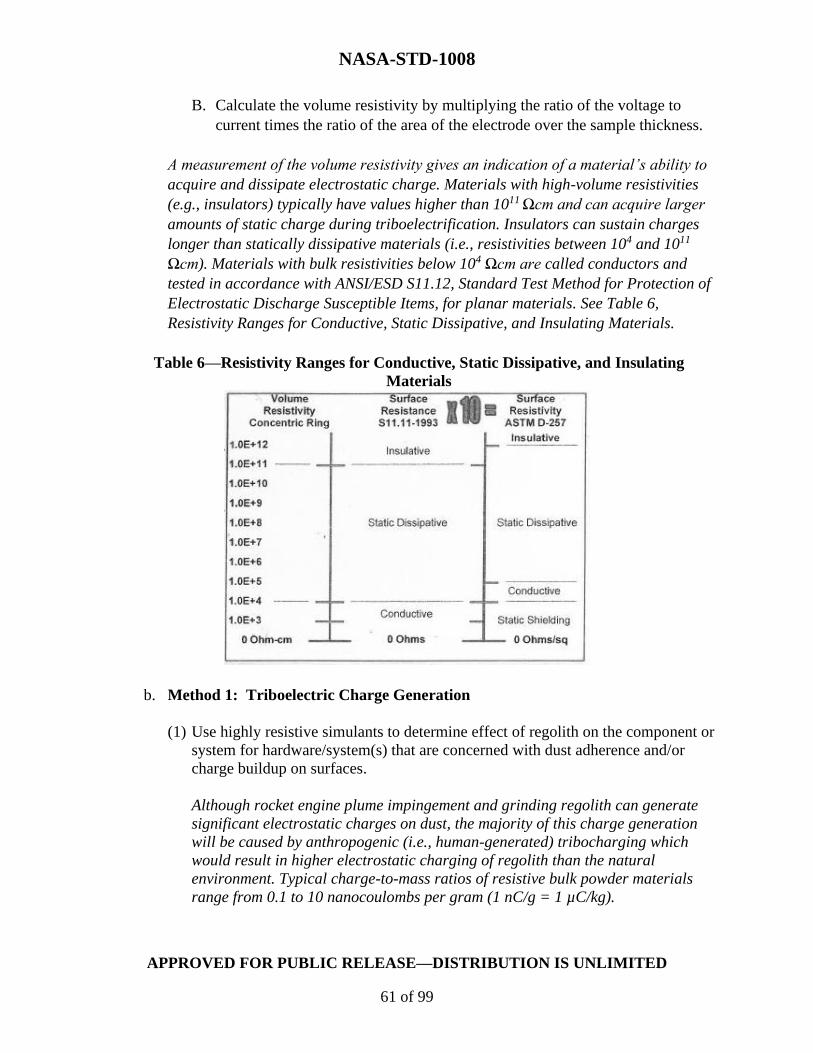
NASA-STD-1008
APPROVED FOR PUBLIC RELEASE—DISTRIBUTION IS UNLIMITED
61 of 99
B. Calculate the volume resistivity by multiplying the ratio of the voltage to
current times the ratio of the area of the electrode over the sample thickness.
A measurement of the volume resistivity gives an indication of a material’s ability to
acquire and dissipate electrostatic charge. Materials with high-volume resistivities
(e.g., insulators) typically have values higher than 1011 Ωcm and can acquire larger
amounts of static charge during triboelectrification. Insulators can sustain charges
longer than statically dissipative materials (i.e., resistivities between 104 and 1011
Ωcm). Materials with bulk resistivities below 104 Ωcm are called conductors and
tested in accordance with ANSI/ESD S11.12, Standard Test Method for Protection of
Electrostatic Discharge Susceptible Items, for planar materials. See Table 6,
Resistivity Ranges for Conductive, Static Dissipative, and Insulating Materials.
Table 6—Resistivity Ranges for Conductive, Static Dissipative, and Insulating
Materials
b. Method 1: Triboelectric Charge Generation
(1) Use highly resistive simulants to determine effect of regolith on the component or
system for hardware/system(s) that are concerned with dust adherence and/or
charge buildup on surfaces.
Although rocket engine plume impingement and grinding regolith can generate
significant electrostatic charges on dust, the majority of this charge generation
will be caused by anthropogenic (i.e., human-generated) tribocharging which
would result in higher electrostatic charging of regolith than the natural
environment. Typical charge-to-mass ratios of resistive bulk powder materials
range from 0.1 to 10 nanocoulombs per gram (1 nC/g = 1 µC/kg).

NASA-STD-1008
APPROVED FOR PUBLIC RELEASE—DISTRIBUTION IS UNLIMITED
62 of 99
(2) Simulate charge-to-mass levels by sieving, shaking, or pouring particles under the
following test conditions.
(3) For other charge generation methods, perform testing to estimate the charge-to-
mass values expected (e.g., plume effects).
Quantification of the charge-to-mass levels can be performed by measuring charge
on the deposited particles using a Faraday cup divided by the mass of the particles in
the cup.
c. Method 2: Electrical Arcing
For hardware/system(s) that are susceptible to electrical arcing or surface discharges, pre-charge
dust simulants using methods described in ISO 11221:2011, Space systems – Space solar panels
– Spacecraft charging induced electrostatic discharge test methods.
[Rationale: All hardware/system(s) exposed to operations on planetary surfaces will likely
encounter planetary dust. Understanding hardware/system performance within or after exposure
to dusty environments is important as this dust has the potential to damage and degrade
operational performance and induce unanticipated hazards to crew safety and health.]
The charged simulant can interact with other spacecraft materials and cause charge buildup on
those materials. Differential charging across insulating spacecraft materials may build to the
point of electrostatic discharge, which can be damaging to materials and hardware/system(s),
including direct damage to electronics and indirect damage (e.g., sputtering of material and
redeposition on optically sensitive components).
Arcing of uninsulated, high-voltage systems occurs in the presence of dense plasmas or sufficient
charge carrier systems. Although the lunar dust is highly resistive, the presence of UV
irradiation can drastically alter its surface conductivity. This lowered resistivity could change
the electrical properties temporarily from an insulating material to a static dissipative material.
If static dissipative particles are present between open high-voltage electrodes, there is a
possibility of a discharge between the electrodes.
5.3.8.1 Simulant Characteristics
The minimum recommended simulant material properties to consider for electrostatics testing
are electrical conductivity, particle size distribution, adhesion, cohesion, and permittivity.
5.3.8.2 Facility Capability
Electrostatics testing should be conducted at facilities with the ability to measure electrostatic
properties of dust. Such electrostatic instrumentation would include, but not be limited to:
charge-to-mass measurement devices (such as Trek 212HS Charge-to-Mass Ratio meter),

NASA-STD-1008
APPROVED FOR PUBLIC RELEASE—DISTRIBUTION IS UNLIMITED
63 of 99
Faraday Cups (model 232 ETS Faraday Cup), volume resistivity of powders (Model 828 Volume
Resistivity of Powder by ETS), current preamplifiers, electrometers, and fieldmeters.
5.3.8.3 Testing Best Practices
5.3.8.3.1 Low Fidelity Testing:
a. Bake-out test materials in a vacuum chamber and/or oven or place in a low humidity
chamber prior to testing to reduce absorbed water, which can lower the resistivity of the samples
by several orders of magnitude.
b. Place desired amount of simulant in sieve to be deposited on surface under low RH
conditions (i.e., <20% RH). Humidity should be as low as possible to capture the electrostatic
environment and retain electrostatic charge on particles.
5.3.8.3.2 High Fidelity Testing:
a. Bake out test materials in a vacuum chamber prior to testing to remove absorbed
water which can lower the resistivity of the samples by several orders of magnitude.
b. Place desired amount of simulant in sieve to be deposited on surface and initiate
vacuum operations. Do not deposit materials until high vacuum is reached. Testing in high
vacuum (i.e., 1.3 x 10⁻⁵ mbar (10-5 Torr)) is preferred to mimic the space environmental
conditions and preclude loss of charge buildup and erroneous results. Note: If deposition is
applied in air, the simulant will lose its charge during the pump-down phase.
5.3.9 Plume Surface Interaction Testing
Rocket engines produce gas plumes that interact with the planetary surface environment. When
vehicles conduct near-surface operations (e.g., landing or take-off), gas plumes interact with
planetary surfaces and may cause erosion, lofting, and/or heating of surface materials. Ejected
dust may strike the vehicle producing the plume, hardware/system(s) in the vehicle’s immediate
vicinity or objects on orbit. PSI may cause dust loading or impact damage (e.g., media blasting).
The nature of PSI effects depends on the target body’s regolith, atmospheric, topographic, and
gravitational properties; the vehicle’s architecture, engine configuration and duty cycle, and the
flight path of the landing vehicle; and the proximity of nearby hardware/system(s).
[DTR 14] Systems and hardware susceptible to effects from PSI shall undergo plume surface
interaction testing to mimic the effect of dust impingement on vehicle surfaces by considering
and replicating, as feasible, the environment and mode of dust interaction.
[Rationale: All hardware/system(s) exposed to landing operations on planetary surfaces will
likely encounter planetary dust. Understanding hardware/system performance within or after
exposure to dusty environments is important as this dust has the potential to damage and
degrade operational performance and induce unanticipated hazards to crew safety and health.

NASA-STD-1008
APPROVED FOR PUBLIC RELEASE—DISTRIBUTION IS UNLIMITED
64 of 99
In most cases, it is not practical to replicate all aspects of PSI in a single test. Therefore, choose
a level of fidelity appropriate to the application. A multi-tiered, phased approach may be needed
to obtain adequate test data. Using the lunar surface as an example, one set of tests might
explore reduced-scale interactions in lunar gravity, while another could be performed at the
flight scale in 1 g. Caution should be exercised when interpreting results as gas-granular
interactions do not typically scale predictably with metrics such as particle size or engine height,
and the effects of gravity level on PSI are often significant.
Note: While this section includes specific guidance for PSI testing, users may also want to
consult section 5.3.2 on Abrasion Testing when considering general erosion wear caused by gas-
entrained particles.
5.3.9.1 Simulant Characteristics
The minimum recommended simulant material properties to consider for plume surface
interaction testing are geotechnical properties, including PSD and morphology; electrostatic
properties, if applicable; and chemical properties, if applicable.
5.3.9.2 Facility Capability
Plume surface interaction testing can occur in a variety of facilities, including vacuum
chambers, regolith testbeds, thrust interaction testbeds, and reduced/microgravity environments.
Choose the combination that is feasible and appropriate as needed.
5.3.9.3 Factors Affecting PSI Testing
Factors that affect PSI testing include:
a. Gravitational acceleration.
b. Atmosphere/ambient pressure.
c. Engine and nozzle properties and configuration.
d. Motion and orientation of nozzle.
e. Thrust duration, pulsing, and start-up shock.
f. Exhaust gas properties, including composition and temperature.
g. Regolith properties, including particle density, PSD, composition, and packing
structure.

NASA-STD-1008
APPROVED FOR PUBLIC RELEASE—DISTRIBUTION IS UNLIMITED
65 of 99
h. Regolith bed depth.
i. Test area volume.
5.3.9.4 Testing Best Practices/Increasing Fidelity
The following best practices provide historical context and lessons learned for ensuring
efficiency and consistency in testing. High-fidelity testing of PSI behaviors is often difficult to
achieve and PSI effects are an area of ongoing research. Low fidelity testing is appropriate
where a sufficiently representative dust load may be achieved for the effect of concern by proper
choice of elements listed below. For example, characterizing the impact effects of dust may not
require performing a hot-fire test; the user instead may choose to entrain and accelerate dust by
other means. Understanding gas flow around and dust effects about a specific vehicle, however,
may require more careful replication of the target environment. The following recommendations
to increase test fidelity reflect factors listed above:
a. Loft or entrain simulant by the same mechanism expected in situ. Granular
mechanics do not scale well; sizing the mechanism of interaction and the area of effect as close
as possible to the predicted use case will produce more representative results.
When higher fidelity experiments are not feasible, gas guns at sea-level that entrain particles can
be used to assess media blasting effects, but particle velocities and ejecta energy flux should
match in situ observations.
b. Regolith simulant should be well characterized and selected to mimic the planetary
surface of interest. The following properties should be characterized and selected as
appropriate: cohesion and angle of internal friction (based on Mohr's Circle), bearing capacity,
shear strength, bulk density, morphology and PSD, compaction, and particle density.
c. If replicating a PSI interaction with a gas jet:
(1) Represent the target environment in particle arrangement, topography, and
packing.
(2) Match simulant depth to the target environment or exceed the expected gas
penetration depth. If possible, match simulant stratigraphy to that of the target
environment.
(3) Ensure the simulant test area exceeds PSI area of effect.
(4) Flight match in scale the propulsion test article in scale, thrust, and chamber
pressure and temperature.
(5) Match the propulsion test article to the expected distance and motion of the flight
vehicle. Short-duration thrust static tests may be substituted for lower fidelity.
d. Match PSI first order parameters to flight: chamber pressure, impingement pressure
and plume expansion ratio, exhaust gas temperature, composition, and density.

NASA-STD-1008
APPROVED FOR PUBLIC RELEASE—DISTRIBUTION IS UNLIMITED
66 of 99
e. Control test area pressure to match atmospheric pressure and the physical
composition of the target environment. The target atmosphere may affect the method and mode
of particle interaction. This includes effects on particle charging, particle trajectory, and rocket
plume behaviors.
f. Match gravitational acceleration to the target environment (best practice), or
simulant density chosen to match the effective weight in the target environment. Densimetric
Froude scaling has been used to correct for differences in gravitational acceleration. In
environments where gravity is less than 1 g, other forces (e.g., cohesion) may dominate. This can
reveal “masked phenomena,” which are behaviors reduced or eliminated in 1 g.
5.4 Simulants
5.4.1 Lunar Simulants
Lunar rocks, core samples, pebbles, and dust samples brought to Earth by the Apollo Program
have a limited availability for use in testing technologies and hardware/system(s)
(https://curator.jsc.nasa.gov/lunar/index.cfm). While recovered meteorites, including lunar and
Martian, are another supply of extraterrestrial materials, these too are in limited supply.
Planetary surface simulants have been developed to reflect physical, mineralogical, or chemical
properties of lunar, Martian, and small body rocks and regolith. These simulants are created
from geologic material collected on Earth that best replicate the petrology, mineralogy, and
chemistry of the different planetary destinations. Various types of glass have been included in
simulants to mimic the impact-generated and volcanic glass components. There is likely not one
simulant that will fulfill all testing physical and compositional needs, and a judicious
understanding and selection of simulants for testing is needed. Additionally, some simulants are
in limited supply or not in production.
For additional details on lunar regolith properties, refer to SLS-SPEC-159H, DSNE. For
simulant guidance, refer to Taylor, et al. (2016), NASA/TP-2006-214605, Lunar Regolith
Simulant Materials: Recommendations for Standardization, Production, and Usage. For
additional simulant descriptions, view the planetary simulant database at
https://simulantdb.com/. Other references are provided below covering a range of simulant
histories, assessments, and uses.
Simulant recommendations are based on the type of testing or purpose of work and the stage of
testing development (i.e., TRL). For each type of test listed in this NASA Technical Standard,
there is a simulant characteristic section where the minimum recommended simulant
characteristics are listed. These characteristics are provided to increase awareness for the user
and are not meant to replace simulant expert advisement. For certain low fidelity testing cases
where particulate matter size scale is the only consideration, ISO 12103-1:2016, Road vehicles -
Test contaminants for filter evaluation, may be a useful precursor to lunar simulant.

NASA-STD-1008
APPROVED FOR PUBLIC RELEASE—DISTRIBUTION IS UNLIMITED
67 of 99
Simulant guidance, inquiries, recommendations, and procurement are facilitated through the
NASA LSII Simulant Advisory Committee. To contact the NASA Simulant Advisory Committee,
go to the following website: https://ares.jsc.nasa.gov/projects/simulants/.
NASA simulant recommendations for evacuation/flow, drilling, abrasion/wear, oxygen
production, and human health studies are provided in NASA/TM-2010-216446, Lunar Regolith
Simulant User’s Guide (. Additions to the Schrader, et al. (2010) document are in progress via
the LSII Simulant Advisory Committee (Gruener, et al., in progress). Additionally, NASA’s
STMD LSII is working with the Johns Hopkins University Applied Physics Laboratory’s (APL)
Lunar Surface Innovation Consortium (LSIC) to characterize and assess commercial lunar
simulants. Table 4 on page 24 accessible at
http://lsic.jhuapl.edu/Resources/files/simulant_eval_2020.pdf summarizes the assessment.
Another source of information pertaining to lunar simulants includes ISO 10788:2014, Space
Systems-Lunar Simulants. ISO 10788 provides a way to compare simulants to regolith via
figures of merit for the purpose of standardizing simulant development. Simulant selection for
each test should be documented with the Dust Class ID.
5.4.2 Martian Simulants
Reserved
5.4.3. Small Bodies Simulants
Reserved
5.5 Facilities
Selection of the appropriate facility for testing with dust is an important step. The guidance in
each of the testing sections of this NASA Technical Standard provides facility capabilities
expected for a given test and desired simulant characteristics. Using the provided guidance, in
addition to visiting the LSIC Facilities Directory described below, the user should have a good
starting point for facility selection.
Selection of the facility will vary depending on the hardware/system(s) being exposed to
simulants. Facilities for testing with dust can range in size from gloveboxes to rock yards. It is
also important to find a facility capable of representing the appropriate environmental
conditions for the test. For instance, a dirty thermal-vacuum (TVAC) chamber may be necessary
for some hardware while excessive for another.
For certain types of tests, the proper equipment or instrumentation is the important factor in
selecting a facility. Oftentimes, several different facilities will be needed to accomplish the series
of tests identified for the hardware. The dust loading distribution (i.e., surface accumulated
loading versus volumetric loading) may also impact selection of facilities.

NASA-STD-1008
APPROVED FOR PUBLIC RELEASE—DISTRIBUTION IS UNLIMITED
68 of 99
Users are encouraged to understand the facility capabilities expected for each type of test. As
test plans are developed, users will determine the appropriate facilities necessary to accomplish
their objectives.
The facility selection process involves understanding the options available for testing. Facilities
are available at NASA Centers, universities, industry, and other government facilities. To
become familiar with dust testing facilities, visit https://lsic-wiki.jhuapl.edu/x/HINf.
LSIC collects and conveys up-to-date information regarding test facilities. To access the LSIC
Facilities Directory, users are first required to create a username and password with LSIC by
visiting http://lsic.jhuapl.edu/. Once access is granted to the LSIC Facilities Directory, users can
search the directory for relevant facilities. Keywords can be searched in the directory to assist in
down-selecting to the appropriate facility. Facility owners can add new facility information here.
The directory includes facility location, name, size configuration, vacuum, temperature range,
volume, point of contact, and other relevant information. Facility selection for each test should
be documented with the Dust Class ID.
Note: Oftentimes, the appropriate facility may not have the ideal simulant. Determine if multiple
tests of varying fidelity are needed to satisfy system requirements. For example, testing the entire
system in a facility with pre-determined simulant may be necessary to accomplish certain test
objectives, followed by a subsystem or component test in a separate facility using a higher
fidelity simulant. Additionally, it is possible that simulant material will erode over time. For
certain types of testing where specific physical characteristics (e.g., angularity or abrasiveness)
are of concern, it may be appropriate to replenish the simulant for subsequent tests.

NASA-STD-1008
APPROVED FOR PUBLIC RELEASE—DISTRIBUTION IS UNLIMITED
69 of 99
APPENDIX A
CONTEXT FOR TESTING THE EFFECTS OF DUST ON
HARDWARE AND SYSTEMS
A.1 PURPOSE
This Appendix provides context for why it is necessary to test and examine the effects of dust on
hardware and systems.
A.2 TESTING THE EFFECTS OF DUST
Traversing the surface of a dusty planetary body brings significant hazards that have to be
addressed as future efforts to return get underway in earnest. This NASA Technical Standard
explains the need for and best means of performing ground testing of hardware/system(s) to
guard against the expected negative effects that dust may bring.
Missions to the Moon, Mars, and small bodies (e.g., asteroids) have noted significant deleterious
effects due to interactions between hardware and fine-grained particulate matter, or dust, from
the local environment. This dust can degrade and damage mechanisms, alter thermal properties,
and obscure optical systems. It can abrade textiles and scratch surfaces. It can affect human
health and safety, and both short- and long-term hardware/system performance. Human activities
in such dusty environments can irreversibly alter the surface environment, while the chemical
components of the dusty surface materials may prove to be a useful resource assuring a
sustainable presence. Therefore, dust has to be considered during spacecraft, habitat, mobility
systems, hardware and systems development, design, and verification to provide and develop
effective and efficient testing and mitigation tools and strategies.
Natural and human-generated dust, in some combination, interact with materials, designs, and
operations, which can affect human health, hardware, and material performance. This includes
the design of dust-tolerant mechanisms, systems, and operations, and all related mitigation
techniques and tools. Developing and utilizing the testing and research facilities that incorporate
simulants and reproduce appropriate fidelity environmental analogues for testing are of great
importance. Incorporating the space flight mantra, ‘test as you fly and fly as you test’ and proven
systems engineering methodologies to produce reproducible results maximizes successful
exploration activities. Researching, analyzing, and examining the effects such dust has on
hardware/system(s) before returning them to the dusty surface environments maximizes lifetime
and safety, decreases hazards, and increases the cost effectiveness of future planetary surface
activities.
See Figure 2, Images of Apollo 17 and 15 Lunar Samples, for images of Apollo lunar samples.

NASA-STD-1008
APPROVED FOR PUBLIC RELEASE—DISTRIBUTION IS UNLIMITED
70 of 99
Figure 2—Images of Apollo 17 and 15 Lunar Samples
Left: A 1 mm copper mesh on finest fraction sieved Apollo 17 samples. Center: Handpicked
Apollo 15 glass beads and lithic fragments. Right: Scanning Electron Microscope image of 600-
micrometer-wide agglutinate particle and a 200-micrometer glass sphere. (Barker, D. C., Apollo
15 and 17 photo/SEM, 2020)

NASA-STD-1008
APPROVED FOR PUBLIC RELEASE—DISTRIBUTION IS UNLIMITED
71 of 99
APPENDIX B
DUST IMPACT ASSESSMENT PROCESS EXAMPLES
B.1 PURPOSE
This Appendix provides examples of hardware and systems, and their associated environmental
and testing profiles using the flow chart in Figure 1 and Table 1.
B.2 EXAMPLES OF HARDWARE
This section provides examples of how to use Figure 1 and Table 1 to determine the dust impact
assessment for various types of hardware and systems. All section references are to this NASA
Technical Standard.
An example of space suit material on the lunar surface:
Step 1. Define Hardware or Systems (Green Box): Exploration Extravehicular Mobility Unit (xEMU)
Pressure Garment System (PGS) on the lunar surface.
Step 2. Working Dust Environment (Box A): Planetary External (PE) is the environment in which the
system will operate. Use the letters PE for Box A in the Dust Class ID.
Step 3. Planetary Body (Box B): The system will be operating on the lunar surface. Use the letter L for
Box B in the Dust Class ID.
Step 4. Sources of Dust (Green Box): Read through appropriate “Sources of Dust” tables in section 4.2
to understand characteristics of dust that may impact the system. Human-generated surface transported
dust may affect this example system.
Step 5. Dust Loading Distribution (Box C): Surface accumulated dust will affect this system. Use the
number 1 for Box C in the Dust Class ID.
Step 6. Particle Size Range (Box D): The maximum particle size of the three possible “Sources of Dust”
is 500 µm. 500 will be used for Box D in the Dust Class ID.
Step 7. Dust Loading (Box E): The maximum surface accumulated loading for the possible “Sources of
Dust” is 40 g/m2. Use 40 for Box E in the Dust Class ID.
Step 8. Test Categories (Box F): System will need abrasion, thermal, and reactivity testing to determine
the performance in the lunar external environment. Use the numbers 2, 4, and 7 for Box F in the Dust
Class ID, which corresponds to sections 5.3.2, 5.3.4, and 5.3.7.
Step 9. Simulant Selection (Orange Box): Make selection using resources in section 5.4.
Step 10. Facility Selection (Orange Box): Make selection using resources in section 5.5.

NASA-STD-1008
APPROVED FOR PUBLIC RELEASE—DISTRIBUTION IS UNLIMITED
72 of 99
Step 11. Perform Tests (Gray Box): Perform validation testing per guidelines in each section and in
accordance with system engineering requirements/success criteria for the use application. See section 5.1
for simulant preparation guidance and section 5.2 for simulant loading guidance.
Step 12. Report Dust Class ID (Black Box): Report dust validation test parameters as PE-L:1-500-40-
2,4,7 in accordance with the Dust Class ID to ensure consistency and repeatability.
An example of a solar panel on the exterior of a lunar orbiter:
Step 1. Define Hardware or Systems (Green Box): Solar panel attached to lunar orbiter.
Step 2. Working Dust Environment (Box A): The system is in orbit; this is an In-Space External (SE)
environment. Use the letters SE in Box A in the Dust Class ID.
Step 3. Planetary Body (Box B): The system orbits the Moon, designated by the letter L. See section 4.1.
Use the letter L in Box B in the Dust Class ID.
Step 4. Sources of Dust (Green Box): Read through appropriate “Sources of Dust” tables in section 4.2
to understand characteristics of dust that may impact the system. Rocket Plume Dust, Natural Charged
Dust Transport, and Natural Impact Dust Transport may affect this system.
Step 5. Dust Loading Distribution (Box C): A volumetric accumulated dust source will affect this system.
Use the number 2 for Box C in the Dust Class ID.
Step 6. Particle Size Range (Box D): The maximum particle size to affect the vehicle varies per test. In
this example, consider Natural Charged Dust Transport, which has a maximum particle size of 0.5 µm.
Use 0.5 for Box D in the Dust Class ID.
Step 7. Dust Loading (Box E): The Dust Loading Distribution is volumetric, with a maximum loading of
0.01 g/m3. Use the value 0.01 for Box E in the Dust Class ID.
Step 8. Test Categories (Box F): System needs abrasion, optical, thermal, reactivity, and electrostatics
testing to determine the performance in the on-orbit lunar environment. Use the numbers 2, 3, 4, 7 and 8
for Box F in the Dust Class ID, which corresponds to sections 5.3.2, 5.3.3, 5.3.4, 5.3.7, and 5.3.8.
Step 9. Simulant Selection (Orange Box): Make selection using resources in section 5.4.
Step 10. Facility Selection (Orange Box): Make selection using resources in section 5.5.
Step 11. Perform Tests (Gray Box): Perform validation testing in accordance with guidelines in each
section and the system engineering requirements/success criteria for the application. See section 5.1 for
simulant preparation guidance and section 5.2 for simulant loading guidance.
Step 12. Report Dust Class ID (Black Box): Report dust validation test parameters as SE-L:2-0.5-
0.0001-2,3,4,7,8 in accordance with the Dust Class ID to ensure consistency and repeatability.

NASA-STD-1008
APPROVED FOR PUBLIC RELEASE—DISTRIBUTION IS UNLIMITED
73 of 99
An example of an optical surface coating on a window on a lander on the lunar surface:
Step 1. Define Hardware or Systems (Green Box): Optical surface coating on a window external surface
of lunar lander vehicle.
Step 2. Working Dust Environment (Box A): Planetary External (PE) is the environment in which the
system will operate. Use the letters PE for Box A in the Dust Class ID, which corresponds to section 4.1.
Step 3. Planetary Body (Box B): The system will be operating on the lunar surface. Use the letter L for
Box B in the Dust Class ID.
Step 4. Sources of Dust (Green Box): Read through appropriate “Sources of Dust” tables in section 4.2
to understand characteristics of dust that may impact the system. Rocket plume dust, natural charged dust
transport, and natural impact dust transport may affect this example system.
Step 5. Dust Loading Distribution (Box C): Surface accumulated dust will affect this system. Use the
number 1 for Box C in the Dust Class ID.
Step 6. Particle Size Range (Box D): The maximum particle size of the three possible “Sources of Dust”
is 1.0 cm. After a conversion from cm to µm, use 10000 for Box D in the Dust Class ID.
Step 7. Dust Loading (Box E): The maximum surface accumulated loading for the three possible
“Sources of Dust” is 40 g/m2. Use 40 for Box E in the Dust Class ID.
Step 8. Test Categories (Box F): The system will need abrasion, optical, thermal, and reactivity testing to
determine the performance in the lunar external environment. Use the numbers 2, 3, 4, and 7 for Box F in
the Dust Class ID, which corresponds to sections 5.3.2, 5.3.3, 5.3.4, and 5.3.7.
Step 9. Simulant Selection (Orange Box): Make selection using resources in section 5.4.
Step 10. Facility Selection (Orange Box): Make selection using resources in section 5.5.
Step 11. Perform Tests (Gray Box): Perform validation testing in accordance with guidelines in each
section and system engineering requirements/success criteria for the application. For this example, a
metric could be the opacity degradation relative to the required performance. See section 5.1 for simulant
preparation guidance and section 5.2 for simulant loading guidance.
Step 12. Report Dust Class ID (Black Box): Report dust validation test parameters in all relevant
documentation as PE-L:1-10000-40-2,3,4,7 in accordance with the Dust Class ID, along with referencing
this NASA Technical Standard to ensure consistency and repeatability.

NASA-STD-1008
APPROVED FOR PUBLIC RELEASE—DISTRIBUTION IS UNLIMITED
74 of 99
An example of a linear actuator inside the crew cabin on the lunar surface.
Step 1. Define Hardware or Systems (Green Box): Linear actuator inside the crew cabin on the lunar
surface.
Step 2. Working Dust Environment (Box A): The hardware is on the surface and inside a pressurized
volume; this is a Planetary Pressurized (PP) environment. Use the letters PP in Box A in the Dust Class
ID.
Step 3. Planetary Body (Box B): The hardware is on the Moon. Use the letter L in Box B in the Dust
Class.
Step 4. Sources of Dust (Green Box): Read through appropriate “Sources of Dust” in section 4.2 to
understand characteristics of dust that may impact the system. EVA Suit Cross-Hatch Transported Dust
and Hardware Cross-Hatch Transported Dust may affect this system.
Step 5. Dust Loading Distribution (Box C): A surface-accumulated dust source will affect this system.
Use the number 1 for Box C in the Dust Class ID.
Step 6. Particle Size Range (Box D): The maximum particle size to affect the vehicle varies per test.
Although Table 3, Planetary Pressurized Lunar Sources of Dust and Associated Dust Parameters, indicates a maximum particle size of 300 µm, it is known that the program’s dust mitigation strategy
involves removing particles greater than 100 µm before entering the cabin. A maximum particle size of
100 µm is selected. Use 100 for Box D in the Dust Class ID.
Step 7. Dust Loading (Box E): The surface-accumulated loading is dependent on program requirements.
Knowing that the requirement is 50 grams per suit per EVA, a total of 500 grams is estimated per mission
planning. The hardware in question has a surface area of approximately .1 m2. To test to worst-case
conditions, the dust loading is set at 500g/0.1m2 of 5000 g/m2. Use 5000 for Box E in the Dust Class ID.
Step 8. Test Categories (Box F): The hardware will need abrasion and mechanisms testing to determine
the performance in the planetary pressurized environment. Use the numbers 2 and 5 for Box F in the Dust
Class ID, which corresponds to sections 5.3.2 and 5.3.5.
Step 9. Simulant Selection (Orange Box): Make selection using resources in section 5.4.
Step 10. Facility Selection (Orange Box): Make selection using resources in section 5.5.
Step 11. Perform Tests (Gray Box): Validation testing will be performed in accordance with guidelines
in each section and system engineering requirements/success criteria for the application. See section 5.1
for simulant preparation guidance and section 5.2 for simulant loading guidance.
Step 12. Report Dust Class ID (Black Box): Report dust validation test parameters as PP-L:1-100-5000-
2,5 in accordance with the Dust Class ID to ensure consistency and repeatability.

NASA-STD-1008
APPROVED FOR PUBLIC RELEASE—DISTRIBUTION IS UNLIMITED
75 of 99
APPENDIX C
REFERENCES
C.1 PURPOSE
This Appendix provides reference material for background information only. The referenced
sections below refer to this NASA Technical Standard. In case of conflict, refer to paragraph 2.4.
C.2 REFERENCE DOCUMENTS
NASA
NPR 7123.1, NASA Systems Engineering Processes and Requirements (Reference section 5.3.4)
NASA-STD-3001, Volume 2, NASA Space Flight Human-System Standard and the Human
Integration Design Handbook. (Reference section 4.2, Tables 2 and 3)
NASA-STD-5017, Design and Development Requirements for Mechanisms. (Reference section
5.3.5.3)
NASA-STD-7012, Leak Test Requirements: Potential Reference for ASNT Nondestructive
Testing Handbook for Leak Testing. (Reference section 5.3.6.3)
NASA/TM-2005-213610, The Effects of Lunar Dust on EVA Systems During the Apollo
Missions. (Reference section 4.2, Table 3)
NASA/TP-2006-214605, Lunar Regolith Simulant Materials: Recommendations for
Standardization, Production, and Usage. (Reference section 5.4)
NASA/TM-2008-213722, An Assessment of Dust Effects on Planetary Surface Systems to
Support Exploration Requirements. (Reference section 1.2)
NASA/CR-2008-215431, Lunar Dust Chemical, Electrical, and Mechanical Reactivity:
Simulation and Characterization. (Reference section 5.3.7)
NASA/TP-2009-214786, Lunar Dust Effects on Spacesuit Systems Insights from the Apollo
Spacesuits. (Reference Table 3.)
NASA/TM-2010-216443, Figure of Merit Characteristics Compared to Engineering Parameters.
(Reference sections 5.3.4 and 5.3.7)

NASA-STD-1008
APPROVED FOR PUBLIC RELEASE—DISTRIBUTION IS UNLIMITED
76 of 99
NASA/TM-2010-216446, Lunar Regolith Simulant User's Guide. (Reference section 5.4)
NASA/TM-2013-217833, Preparation of a Frozen Regolith Simulant Bed for ISRU Component
Testing in a Vacuum Chamber. (Reference sections 5.1.2 and 5.4)
NASA/TM-86556, Lubrication Handbook for the Space Industry. Part A: Solid Lubricants. Part
B: Liquid Lubricants. (Reference section 5.3.5)
NASA-CR-2252, Site Alteration Effects from Rocket Exhaust Impingement During a Simulated
Viking Mars Landing. Part 1: Nozzle Development and Physical Site Alternation. (Reference
section 5.3.9.4)
NASA-CR-4404, Lunar Dust Transport and Potential Interactions with Power System
Components. (Reference section 4.2, Table 2)
NASA-SP-8013, Meteoroid Environment Model—l969 (Near Earth to Lunar Surface).
(Reference section 4.2, Table 2)
SLS-SPEC-159H, Cross-Program Design Specification for Natural Environments (DSNE).
(Reference section 4.2, Table 2 and Table 5 and sections 5.1.1 and 5.4)
American Society for Testing and Materials (ASTM)
ASTM B611-13 (2018), Standard Test Method for Determining the High Stress Abrasion
Resistance of Hard Materials. (Reference section 5.3.2)
ASTM C117-17, Standard Test Method for Materials Finer than 75-μm (No. 200) Sieve in
Mineral Aggregates by Washing. (Reference section 5.1.1)
ASTM C136/C136M-19, Standard Test Method for Sieve Analysis of Fine and Coarse
Aggregates. (References section 5.1.1)
ASTM D1140-17, Standard Test Methods for Determining the Amount of Material Finer than
75-μm (No. 200) Sieve in Soils by Washing. (Reference section 5.1.1)
ASTM D2216, Standard Test Methods for Laboratory Determination of Water (Moisture)
Content of Soil and Rock by Mass. (Reference section 5.1.2)
ASTM D3884-09 (2017), Standard Guide for Abrasion Resistance of Textile Fabrics (Rotary
Platform, Double-Head Method). (Reference section 5.3.2)
ASTM D4966-12 (2016), Standard Test Method for Abrasion Resistance of Textile Fabrics
(Martindale Abrasion Tester Method). (Reference section 5.3.2)
NASA-STD-1008
APPROVED FOR PUBLIC RELEASE—DISTRIBUTION IS UNLIMITED
77 of 99
ASTM G77-17, Standard Test Method for Ranking Resistance of Materials to Sliding Wear
using Block-on-Ring Wear Test. (Reference section 5.3.5)
International Organization for Standardization (ISO)
ISO 11221:2011, Space systems - Space solar panels - Spacecraft charging induced electrostatic
discharge test methods. (Reference section 5.3.8)
ISO 28080:2011, Hardmetals- Abrasion tests for hardmetals (Reference section 5.3.2)
ISO 10788:2014, Space systems - Lunar simulants. (Reference section 5.4)
ISO 17892-4:2016, Geotechnical investigation and testing - Laboratory testing of soil- Part 4:
Determination of particle size distribution. (Reference section 5.1.1)
ISO 12103-1:2016, Road vehicles - Test contaminants for filter evaluation. (Reference section
5.4)
ISO 14644-1:2015, Cleanrooms and associated controlled environments – Part 1: Classification
of air cleanliness by particle concentration. (Reference section 1.2 and 5.3.1)
ISO 14644-2:2015, Cleanrooms and associated controlled environments – Part 2: Monitoring to
provide evidence of cleanroom performance related to air cleanliness by particle concentration.
(Reference section 5.3.1)
ISO 14644-3:2019, Cleanrooms and associated controlled environments - Part 3: Test methods.
(Reference section 5.3.1)
U.S. Geological Survey
USGS-OFR-2005-1230, Open-File Report Quality-assurance plan for the analysis of fluvial
sediment by the U.S. Geological Survey Kentucky Water Science Center Sediment Laboratory.
(Reference section 5.1.1)
Department of Defense (DoD)
MIL-STD-810G, Test Method Standard: Environmental Engineering Considerations and
Laboratory Tests (Reference section 5.3.2)
American National Standards Institute (ANSI)/ESD Association
ANSI/ESD S11.12, Standard Test Method for Protection of Electrostatic Discharge Susceptible
Items - Volume Resistance Measurement of Static Dissipative Planar Materials (Reference
section 5.3.8)
NASA-STD-1008
APPROVED FOR PUBLIC RELEASE—DISTRIBUTION IS UNLIMITED
78 of 99
Other Documents
Afshar-Mohajer, N., Wu, C. Y., Curtis, J. S., & Gaier, J. R. (2015). Review of dust transport and
mitigation technologies in lunar and Martian atmospheres. Advances in Space Research, 56(6),
1222-1241. (Reference section 4 and section 4.2, Table 2)
Alexander, J. D., Roberds, W. M., & Scott, R. F. (1966). Soil erosion by landing rockets final
report. National Aeronautics and Space Administration. (Reference section 5.3.9.4)
Alvarez, R. (1975). Lunar and terrestrial sample photoconductivity. Proceedings of the Lunar
and Planetary Science Conference. (Reference section 5.3.8)
Aronowitz, L., Koch, F., Scanlon, J. H., & Sidran, M. (1968). Contamination of lunar surface
samples by the lunar module exhaust. Journal of Geophysical Research, 73(10), 3231-3238.
(Reference section 5.3.9.4)
Backer, D. (1971). Lunar Roving Vehicle: Design Report. Spaceflight, 13, 234-240. (Reference
section 4.2 Table 2)
Baron, P.A. and Willeke, K. (2001). Aerosol Measurement: Principles, Techniques, and
Applications, 2nd Edition. Wiley Interscience. (Reference section 5.1.1)
Buhler, C. R., Calle, C. I., Clements, S. J., Mantovani, J., & Ritz, M. I. (2007). In situ test
method for the electrostatic characterization of lunar dust. Proceedings of the IEEE Aerospace
Conference. (Reference section 5.3.8)
Burmeister, C. F., & Kwade, A. (2013). Process engineering with planetary ball mills. Chemical
Society Reviews, 42(18), 7660-7667. (Reference section 5.3.7)
Chambers, W. (2020). Experimental and Computational Investigation of Plume Surface
Interactions in Vacuum Microgravity. [Doctoral dissertation, University of Central Florida].
(Reference section 5.3.9.4)
Clark, L. V. (1970). Effect of retrorocket cant angle on ground erosion-a scaled Viking study.
National Aeronautics and Space Administration. (Reference section 5.3.9.4)
Colwell, J. E., Batiste, S., Horányi, M., Robertson, S., & Sture, S. (2007). Lunar surface: Dust
dynamics and regolith mechanics. Reviews of Geophysics, 45(2). (Reference section 4.2 Table 2
and Table 5)
Colwell, J. E., Robertson, S. R., Horányi, M., Wang, X., Poppe, A., & Wheeler, P. (2009). Lunar
dust levitation. Journal of Aerospace Engineering, 22(1), 2-9. (Reference section 4.2 Table 2 and
Table 5)

NASA-STD-1008
APPROVED FOR PUBLIC RELEASE—DISTRIBUTION IS UNLIMITED
79 of 99
Donahue, C. M., Metzger, P. T., & Immer, C. D. (2005). Empirical Scaling Laws of Rocket
Exhaust Cratering. Proceedings of the 56th International Astronautical Congress. (Reference
section 5.3.9.4)
Fagury-Neto, E., & Kiminami, R. H. (2001). Al2O3/mullite/SiC powders synthesized by
microwave-assisted carbothermal reduction of kaolin. Ceramics International, 27(7), 815-819.
(Reference section 5.3.7)
Forward, K. M., Lacks, D. J., & Sankaran, R. M. (2009). Triboelectric charging of lunar regolith
simulant. Journal of Geophysical Research: Space Physics, 114(A10). (Reference section 4.2,
Table 2)
Greenley, R., Robert, M. H. (1991). Sand and dust on Mars. Proceedings of the NASA Mars
Science Working Group. (Reference section 4.2, Table 2)
Heiken, G. H., Vaniman, D. T., & French, B. M. (1991). Lunar Sourcebook, a user's guide to the
Moon. Cambridge University Press. (Reference section 5.4)
Hibbitts, C. A., Grieves, G. A., Psoton, M. J., Dyar, M. D., Alexander, A. B., Jonson, M. A. and
Orlando, T. M. (2011). Thermal stability of water and hydroxyl on the surface of the Moon from
temperature-programmed desorption measurements of lunar analog materials. Icarus, 213(1), 64-
72. (Reference section 5.1.2)
Higgins, I., & Hendry, A. (1986). Production of Beta-sialon by carbothermal reduction of
kaolinite. British ceramic. Transactions and Journal, 85(5), 161-166. (Reference section 5.3.7)
Hinds, W. C. (1999). Aerosol technology: properties, behavior, and measurement of airborne
particles. (Chapter 16.1, 16.3, 16.5). John Wiley & Sons. (Reference section 5.3.1.3)
Hollick, M., and O'Brien, B. (2013). Lunar weather measurements at three Apollo sites 1969–
1976. Space Weather, 11(11), 651–660. (Reference section 4.1, Table 2)
Hsiao, T. C., Chen, D., Li, L., Greenberg, P., & Street, K. W. (2010). Development of a multi-
stage axial flow cyclone. Aerosol Science and Technology, 44(4), 253-261. (Reference section
5.1.1)
Hsiao, T. C., Chen, D., Greenberg, P. S., & Street, K. W. (2011). Effect of Geometric
Configuration on Collection Efficiency of Axial Flow Cyclones. Journal of Aerosol Science,
42(2) (2011), 78-86. (Reference section 5.1.1)
Hsu, H. W., & Horanyi, M. (2012). Ballistic motion of dust particles in the Lunar Roving
Vehicle dust trails. American Journal of Physics, 80(5), 452-456. (Reference section 4.2, Table
2)

NASA-STD-1008
APPROVED FOR PUBLIC RELEASE—DISTRIBUTION IS UNLIMITED
80 of 99
Immer, C., Lane, J., Metzger, P., & Clements, S. (2008). Apollo video photogrammetry
estimation of plume impingement effects. Proceedings of the ASCE Aerospace Division
International Conference on Engineering, Construction and Operations in Challenging
Environments. (Reference section 4.2)
Immer, C., Metzger, P., Hintze, P. E., Nick, A., & Horan, R. (2011). Apollo 12 lunar module
exhaust plume impingement on lunar Surveyor III. Icarus, 211(2), 1089-1102. (Reference
section 4.2, Table 2 and Table 5)
Jackson, T. L., Farrell, W. M. and Zimmerman, M. I. 2015. Rover wheel charging on the lunar
surface. Advances in Space Research, 55, 1710–1720. (Reference section 4.2, Table 2)
Jackson, T. L., Farrell, W. M., Killen, R. M., Delory, G. T., Halekas, J. S. and Stubbs, T. J.
(2011). Discharging of Roving Objects in the Lunar Polar Regions. Journal of Spacecraft and
Rockets, 48, 4, 700-703. (Reference section 4.2, Table 2)
James, J. T., Lam, C., Scully, R.R., Meyers, V. E., McCoy, J. T. (2014). Lunar dust toxicity:
final report. Lunar Airborne Dust Toxicity Assessment Group (LADTAG). (Reference section 4.2,
Table 4)
Jett, T., Street, K., Abel, P., & Richmond, R. (2008). Lunar dust simulant in mechanical
component testing-paradigm and practicality. Proceedings of the Space Technology and
Applications International Forum. (Reference section 5.3.5)
Juhasz, A. Z., & Opoczky, L. (1990). Mechanical activation of minerals by grinding pulverizing
and morphology of particles (pp.1−42). Ellis Horwood Ltd. Publishers/John Wiley & Sons.
(Reference section 5.3.7)
Kleinhenz, J. E. (2014). Lunar polar environmental testing: Regolith simulant conditioning. In
7th Symposium on Space Resource Utilization (p. 0689). (Reference section 5.1.2)
Kulkarni, P., Baron, P. A., & Willeke, K. (2011). Aerosol measurement: Principles, techniques,
and applications. John Wiley & Sons. (Reference section 5.3.1.3)
Land, N. S., & Clark, L. V. (1965). Experimental investigation of jet impingement on surfaces of
fine particles in a vacuum environment. National Aeronautics and Space Administration.
(Reference section 5.3.9.4)
Land, N. S., & Scholl, H. F. (1969). Scaled lunar module jet erosion experiments (Vol. 5051).
National Aeronautics and Space Administration. (Reference section 5.3.9.4)
Lane, J. E., Metzger, P. T., Immer, C. D., & Li, X. (2008). Lagrangian trajectory modeling of
lunar dust particles. In Earth & Space 2008: Engineering, Science, Construction, and Operations
in Challenging Environments (pp. 1-9). (Reference sections 4.2. Table 2 and Table 5)

NASA-STD-1008
APPROVED FOR PUBLIC RELEASE—DISTRIBUTION IS UNLIMITED
81 of 99
Lane, J. E., & Metzger, P. T. (2015). Estimation of Apollo lunar dust transport using optical
extinction measurements. Acta Geophysica, 63(2), 568-599. (Reference section 5.3.9.4)
Li, D., Wang, Y., Zhang, H., Zhuang, J., Wang, X., Wang, Y., et al. (2019). In situ
measurements of lunar dust at the Chang'E‐3 landing site in the northern Mare Imbrium. Journal
of Geophysical Research: Planets, 124. (Reference section 4.2, Table 2)
Liu, D., Yang, S., Wang, Z., Liu, H., Cai, C., & Wu, D. (2010). On rocket plume, lunar crater
and lunar dust interactions. In 48th AIAA Aerospace Sciences Meeting Including the New
Horizons Forum and Aerospace Exposition (p. 1161). (Reference section 5.3.9.4)
Liu, Y., & Taylor, L. A. (2011). Characterization of lunar dust and a synopsis of available lunar
simulants. Planetary and Space Science, 59(14), 1769-1783. (Reference section 5.4)
Lu, Y., & Thomas, S. (2015). Anm model approach for lunar soil simulant properties study. In
Earth and Space 2014 (pp. 76-83). (Reference section 5.4)
Mazumder, M. K., Saini, D., Biris, A. S., Sriama, P. K., Calle, C., & Buhler, C. (2004). Mars
dust: Characterization of particle size and electrostatic charge distribution. Proceedings of the
Lunar and Planetary Science Conference. (Reference section 4.2, Table 3)
McKay, D. S., Cooper, B.L., Taylor, L. A., James, J. T., Thomas-Keprta, K., Pieters, C. M.,
Wentworth, S. J., Wallace, W. T. and Lee, T. S. (2015). Physicochemical properties of
respirable-size lunar dust. Acta Astronautica, 107, 163-176. (Reference section 4.2, Table 4 and
5.3.7)
Mehta, M., Renno, N. O., Marshall, J., Rob Grover, M., Sengupta, A., Rusche, N. A., Kok, J. F.,
Arvidson, R. E., Markiewicz, W. J., Lemmon, M. T., & Smith, P. H. (2011). Explosive erosion
during the Phoenix landing exposes subsurface water on Mars. Icarus, 211(1), 172–194.
(Reference section 5.3.9.4)
Metzger, P. T., Lane, J. E., & Immer, C. D. (2008). Modification of Roberts' theory for rocket
exhaust plumes eroding lunar soil. In Earth & Space 2008: Engineering, Science, Construction,
and Operations in Challenging Environments (pp. 1-8). (Reference section 5.3.9.4)
Metzger, P. T., Immer, C. D., Donahue, C. M., Vu, B. M., Latta, R. C., & Deyo-Svendsen, M.
(2009). Jet-induced cratering of a granular surface with application to lunar spaceports. Journal
of Aerospace Engineering, 22(1), 24–32. (Reference section 5.3.9.4)
Metzger, P. T., Smith, J., & Lane, J. E. (2011). Phenomenology of soil erosion due to rocket
exhaust on the Moon and the Mauna Kea lunar test site. Journal of Geophysical Research:
Planets, 116(E6). (Reference sections 4.2 and 5.3.9.4)
NASA-STD-1008
APPROVED FOR PUBLIC RELEASE—DISTRIBUTION IS UNLIMITED
82 of 99
Metzger, P. T., & Britt, D. T. (2019). Mitigating lander plume effects with space resources.
Proceedings of the Lunar ISRU 2019. (Reference section 5.3.9.4)
Metzger, P. T. (2020). Dust transport and its effect due to landing spacecraft. Proceedings of the
Impact of the Lunar dust on Human Exploration. (Reference section 5.3.9.4)
Moore, M. E., & McFarland, A. R. (1990). Design of Stairmand-type sampling cyclones.
American Industrial Hygiene Association Journal, 51(3), 151-159. (Reference section 5.1.1)
Morris, A. B., Goldstein, D. B., Varghese, P. L., & Trafton, L. M. (2015). Approach for
modeling rocket plume impingement and dust dispersal on the moon. Journal of Spacecraft and
Rockets, 52(2), 362-374. (Reference section 4.2, Table 2 and section 5.3.9.4)
Nieuwstadt, F. T., & Dirkzwager, M. (1995). A fluid mechanics model for an axial cyclone
separator. Industrial & Engineering Chemistry Research, 34(10), 3399-3404. (Reference section
5.1.1)
Novick, V. J., & Alvarez, J. L. (1987). Design of a multistage virtual impactor. Aerosol Science
and Technology, 6(1), 63-70. (Reference section 5.1.1)
O'Brien, B. (2009). Direct active measurements of movements of lunar dust: Rocket exhausts
and natural effects contaminating and cleansing Apollo hardware on the Moon in 1969.
Geophysical Research Letters, 36(9). (Reference section 4.1, Table 2 and section 5.3.9.4)
O'Brien, B., & Hollick, M. (2015). Sunrise-driven movements of dust on the Moon: Apollo 12
Ground-truth measurements. Planetary and Space Science, 119, 194-199. (Reference section 4.1,
Table 2)
Olhoeft, G. R., Frisillo, A. L., & Strangway, D. W. (1974). Electrical properties of lunar soil
sample 15301, 38. Journal of Geophysical Research, 79(11), 1599-1604. (Reference section
5.3.8)
Plemmons, D. H., Mehta, M., Clark, B. C., Kounaves, S. P., Peach, L. L., Renno, N. O.,
Tamppari, L. and Young, S. M. M. (2008). Effects of the Phoenix Lander descent thruster plume
on the Martian surface. Journal of Geophysical Research: Planets, 113(E3). (Reference section
5.3.9.4)
Sengupta, A., Kulleck, J., Sell, S., Van Norman, J., Mehta, M., & Pokora, M. (2009). Mars
lander engine plume impingement environment of the Mars Science Laboratory. In 2009 IEEE
Aerospace Conference (pp. 1-10). (Reference section 5.3.9.4)
Siddiqi, S. A., & Hendry, A. (1985). The influence of iron on the preparation of silicon nitride
from silica. Journal of Materials Science, 20(9), 3230-3238. (Reference section 5.3.7)
NASA-STD-1008
APPROVED FOR PUBLIC RELEASE—DISTRIBUTION IS UNLIMITED
83 of 99
Simor, M., Cernak, M., Imahori, Y., Stefecka, M., & Kando, M. (2003). Atmospheric-pressure
plasma treatment of polyester nonwoven fabrics for electroless plating. Surface and Coatings
Technology, 172(1), 1-6. (Reference section 5.3.7)
Smith, W. B., Wilson, Jr, R. R., & Harris, D. B. (1979). A five-stage cyclone system for in situ
sampling. Environmental Science & Technology, 13(11), 1387-1392. (Reference section 5.1.1)
Status of lunar regolith simulants and demand for Apollo lunar samples (2010). Proceedings of
the Simulant Working Group of the LEAG-CAPTEM to the Planetary Science Subcommittee of
the NASA Advisory Council. (Reference section 5.4)
Street, Jr., K. W., Ray, C., Rickman, D., & Scheiman, D. A. (2010). Thermal properties of lunar
regolith simulants. In Earth and Space 2010: Engineering, Science, Construction, and
Operations in Challenging Environments (pp. 266-275). (Reference section 5.1.2)
Sung, M. D., Dent, N. M. and Kalechofsky, N. (2007). Ultra fine particle size classification via
sieving in liquid nitrogen. Proceedings of the PARTEC 2007 International Congress on Particle
Technology. (Reference section 5.1.1)
Suryanarayana, C. (2001). Mechanical alloying and milling. Progress in Materials Science,
46(1-2), 1-184. (Reference section 5.3.7)
Taylor, L. A., & Liu, Y. (2010). Important considerations for lunar soil simulants. In Earth and
Space 2010: Engineering, Science, Construction, and Operations in Challenging Environments
(pp. 106-118). (Reference section 5.4)
Taylor, L. A., Pieters, C. M. and Britt, D. (2016). Evaluations of lunar regolith simulants.
Planetary and Space Science, 126, 1-7. (Reference section 5.4)
Tsai, C. J., Chen, D. R., Chein, H. M., Chen, S. C., Roth, J. L., Hsu, Y. D., Li, W. and Biswas, P.
(2004). Theoretical and experimental study of an axial flow cyclone for fine particle removal in
vacuum conditions. Journal of Aerosol Science, 35(9), 1105-1118. (Reference section 5.1.1)
Tsai, C. J., Chen, S. C., Przekop, R., & Moskal, A. (2007). Study of an axial flow cyclone to
remove nanoparticles in vacuum. Environmental Science & Technology, 41(5), 1689-1695.
(Reference section 5.1.1)
Vizcaino, J., & Mehta, M. (2015). Quantification of plume-soil interaction and excavation due to
the sky crane descent stage. Proceedings of the AIAA SciTech 2015. (Reference section 5.3.9.4)
Vondrak, R. R. (1974). Creation of an artificial lunar atmosphere. Nature, 248(5450), 657-659.
(Reference section 4.1, Table 2)

NASA-STD-1008
APPROVED FOR PUBLIC RELEASE—DISTRIBUTION IS UNLIMITED
84 of 99
Wallace, W. T., Taylor, L. A., Liu, Y., Cooper, B. L., McKay, D. S., Chen, B., & Jeevarajan, A.
S. (2009). Lunar dust and lunar simulant activation and monitoring. Meteoritics & Planetary
Science, 44(7), 961-970. (Reference section 5.3.7)
Willman, B. M., & Boles, W. W. (1995). Soil-tool interaction theories as they apply to lunar soil
simulant. Journal of Aerospace Engineering, 8(2), 88-99. (Reference section 5.4)
Zarzycki, P. K., & Katzer, J. (2018). Assessment of lunar soil simulants based on multivariate
statistics. In Earth and Space 2018: Engineering for Extreme Environments (pp. 1-7). (Reference
section 5.4)
Zhang, H., Wang, Y., Chen, L., Zhang, H., Li, C., Zhuang, J., Li, D., Wang, Y., Yang, S., Li, X.
and Wang, W. (2020). In situ lunar dust deposition amount induced by lander landing in
Chang’E-3 mission. Science China Technological Sciences, 63(3), 520-527. (Reference section
5.3.9.4)
Databases:
https://ares.jsc.nasa.gov/projects/simulants/
https://curator.jsc.nasa.gov/lunar/index.cfm
https://lsic-wiki.jhuapl.edu/x/HINf
https://simulantdb.com/

NASA-STD-1008
APPROVED FOR PUBLIC RELEASE—DISTRIBUTION IS UNLIMITED
85 of 99
APPENDIX D
REQUIREMENTS COMPLIANCE MATRIX
D.1 Purpose
Due to the complexity and uniqueness of space flight, it is unlikely that all of the requirements in a NASA technical standard will
apply. The Requirements Compliance Matrix contains this NASA Technical Standard’s technical authority requirements and may be
used by programs and projects to indicate requirements that are or not applicable. Enter “Yes” in the “Applicable” column if the
requirement is applicable to the program or project or “No” if the requirement is not applicable to the program or project. The
“Comments” column may be used to provide specific instructions on how to apply the requirement or to specify proposed tailoring.
NASA-STD-1008
Section Description Requirement in this Standard
Applicable
(Enter Yes
or No)
Comments
4.1 Dust Impact Assessment
Process
[DTR 1] Systems and hardware subjected to planetary dust shall be defined,
classified, tested, and documented in accordance with Figure 1, Dust Impact
Assessment Process, and Table 1, Dust Impact Assessment Process Steps.

NASA-STD-1008
APPROVED FOR PUBLIC RELEASE—DISTRIBUTION IS UNLIMITED
86 of 99
NASA-STD-1008
Section Description Requirement in this Standard
Applicable
(Enter Yes
or No)
Comments
Figure 1—Dust Impact Assessment Process
Test CategoriesIn which ways could dust
cause performance degradation in your
system? (Sections 5.3.1 –5.3.9)
For each test
category:
Simulant SelectionSelect a dust simulant
using key parameters and consult with Simulant Advisory Committee
(Section 5.4)
Facility SelectionSelect a test facility
using key parameters listed and consult Facilities database
(Section 5.5)
Perform TestsPerform each test set. Use
success criteria per application’s system
engineering criteria. See Section 5.1 & 5.2 for simulant
preparation and loading.
Working Dust Environment
In what environment will your system be used?
Planetary BodyIn which planetary body
will your system operate?
Sources of DustUsing the
recommendations provided in Tables
1-4, select test parameters from
Steps 5-7.Enter Letter in Box APE = Planetary ExternalPP = Planetary PressurizedSP = In-Space Pressurized SE = In-Space External
Enter Letter in Box BL = LunarM = MarsSB = Small Body
Particle Size Range
(Tables 1-4)
Enter in Box DEnter the maximum number from range
in
Enter in Box E• If Box C is “1,”
enter the number in g/m2.
• If Box C is “2,” enter the number in g/m3.
• If milligrams scale is needed, put an “m” after the number.
Dust Loading Distribution
Will your system be impacted by volumetric
dust, surface accumulated dust, or
both?
Enter in Box CIf both, you will need 2 separate Dust Class IDs
1 = Surface Accumulated2 = Volumetric
Enter in Box F1= Aerosol Ingestion2 = Abrasion3 = Optical4 = Thermal 5 = Mechanisms6 = Seals & Mating Surfaces7 = Reactivity8 = Electrostatic9 = Plume Surface Interaction
PP - L : 1 - 50 - 20 - 2,4,5
Box CDust Loading Distribution
Box DParticle Size Range (
Box EDust Loading
(g/m2 or g/m3)
Box FTest
Categories
Box BPlanetary
Body
Box AWorking Dust Environment
Define Hardware or
SystemsWhat hardware or system will be exposed to
dust?
Step 1 Step 2 Step 3 Step 4 Step 5 Step 6
Step 8 Step 10 Step 11
Dust Loading: Surface or Volumetric
Step 7 Step 9
Report Dust Class IDAlpha-numeric code
used to document test protocols and values. In this example, the
Dust Class ID =PP-L:1-50-20-2,4,5
Step 12

NASA-STD-1008
APPROVED FOR PUBLIC RELEASE—DISTRIBUTION IS UNLIMITED
87 of 99
NASA-STD-1008
Section Description Requirement in this Standard
Applicable
(Enter Yes
or No)
Comments
Table 1 – Dust Impact Assessment Process Steps STEPS
1 Define Hardware or Systems (Green Box)
Knowing the hardware or system(s) that require design, testing, and validation in a dusty
environment, go through each subsequent step and make appropriate choices. An alpha-numeric
code (i.e., Dust Class ID) can be derived from those choices for archiving and future
comparison or repetition needs.
2 Working Dust Environment (Box A)
Choose the most appropriate “Working Dust Environment” where dust will eventually impact
hardware/system(s). There are four unique environments—two on the planetary surface and
two in space: Planetary external (PE), planetary pressurized (PP), in-space pressurized (SP),
and in-space external (SE). More than one environment may be applicable. In this case, this
process should be followed separately for each environment and will result in multiple Dust
Class IDs.
a. PE refers to the operating environment as the planetary surface (i.e., has a gravity field).
Systems operating will be exposed to the natural planetary surface environment (i.e.,
pressures, temperatures, radiation) and would have direct exposure to the planetary regolith.
This includes dust-induced movement due to human action and operations.
b. PP refers to an operating environment inside pressurized enclosures that are located on the
planetary surface (e.g., inside a human habitat, lander, or pressurized rover). Dust in this
environment refers to planetary material that enters through operational processes (e.g.,
being tracked in on space suits or being brought in on tools or sealing surfaces).
c. SP refers to an operating environment inside pressurized enclosures that are in space (e.g.,
the interior of an orbital habitat or space station in a microgravity environment). Dust in this
environment is planetary material that enters through operational processes. Dust can also be
transferred through inter-module ventilation. The difference between SP and PP volumes is
primarily the gravity vector, which may impact the environmental (“airborne”) dust
conditions. These volumes may be the same structures as planetary pressurized volumes
(e.g., a human ascent vehicle that functions as a habitat both on the planetary surface and in

NASA-STD-1008
APPROVED FOR PUBLIC RELEASE—DISTRIBUTION IS UNLIMITED
88 of 99
NASA-STD-1008
Section Description Requirement in this Standard
Applicable
(Enter Yes
or No)
Comments
space) or may be a secondary volume (e.g., orbital space station), which may see traffic from
a planetary surface.
d. SE refers to an operational environment that is external to a structure in space (e.g., the
exterior of an orbital habitat or space station in a microgravity environment). Dust in this
environment could come from the surface of an ascent vehicle which docks to the asset. For
example, dust on the exterior of the ascent vehicle could transfer to the exterior surface of a
space station via mechanical or electrostatic agitation. Another source could be dust from the
planetary surface that has been propelled beyond escape velocity, either naturally or from
landing PSI (e.g., a vehicle’s thrusters ejecting surface materials at very high speeds).
3 Planetary Body (Box B)
Identify the “Planetary Body” where the hardware or systems are intended to operate: Lunar,
Mars, or Small Body.
4 Sources of Dust (Green Box)
Read through section 4.2 in this NASA Technical Standard corresponding to the designated
planetary body that defines how the dust could be generated relative to your
hardware/system(s). Consider which source(s) of dust may impact your system using the tables
in section 4.2 as guidelines. If multiple sources are applicable, use the worst-case.
5 Dust Loading Distribution (Box C)
Choose the expected “Dust Loading Distribution,” surface accumulated or volumetric. In the
tables in section 4.2 of this NASA Technical Standard, recommendations are given as to the
dust exposure levels that may result. These recommendations should be used to select which
dust characteristics and parameters to use for testing. This box is closely tied to Box E.
a. Surface Accumulated Loading: Defines quantities of dust that may accumulate on
exposed surfaces or that might be mechanically ingrained in surface materials.
Accumulation would be dependent on the dust source, time of exposure, and distance
from the dust source. Instead of reproducing these conditions in a test environment
and allowing dust to settle and accumulate, the system can be coated with the
appropriate mass of dust prior to the test. The amount of dust accumulating in any
environment should be taken as the worst-case loading. Optimization is based on
assumptions for ranges of primary or expected interest (i.e., a priori requirements,
measurements, or modeled conditions, as will be expected during dust particle

NASA-STD-1008
APPROVED FOR PUBLIC RELEASE—DISTRIBUTION IS UNLIMITED
89 of 99
NASA-STD-1008
Section Description Requirement in this Standard
Applicable
(Enter Yes
or No)
Comments
movement and settling). Users should consider what surfaces of their
hardware/system(s) will be exposed to and impacted by dust accumulation. These
numbers define the full accumulation over a specified interval on that surface upon
exposure, thus encompassing adhesion effects. The surface area (m2) is the surface
area of the hardware where dust is being deposited. The mass (g) is the amount of dust
being deposited onto the surface area.
b. Volumetric Loading: The amount of dust that is held/placed in suspension in a given
environment will be impacted by pressure and gravity levels. Volumetric loading refers
to dust that is aloft and is defined in terms of mass per unit volume. For indoor spaces,
this is also referred to as aerosol mass concentration. While this would ultimately
impact surface accumulation through gravitational settling, this volumetric loading is
meant for hardware/system(s) that are directly impacted by actively aloft dust, like
systems that could ingest particulate matter from the environment (e.g., fans) or optical
systems where lofted dust may cause interference or light dispersion. In the Test
Categories (Step 8), volumetric loading primarily impacts the Aerosol Ingestion Testing
section (section 5.3.1 of this NASA Technical Standard). Not all lofted dust in an
atmosphere is considered an aerosol; for example, dust lofted in the tenuous lunar
exosphere is not considered an aerosol, by definition. Categories are optimized based on
assumptions for ranges of primary or expected interest (i.e., a priori requirements,
measurements, or modeled conditions, as will be expected during dust particle
movement and settling).
6 Particle Size Range (Box D)
Choose the appropriate “Particle Size Range” expected to affect your hardware/system(s) based
on the recommendations for each of the sources of dust in section 4.2 of this NASA Technical
Standard that might impact/affect the hardware/system(s). For identification, use only the
maximum expected particle size of the chosen range for the Dust Class ID notation value. The
definition of “dust” in this NASA Technical Standard is the maximum particle size(s) that will
likely cause the most concern for a particular system. Box D is where that particle size is noted.
Based on the sources of dust that will impact the system, select the number associated with the
largest range for use in testing. Ranges are defined as all particulate matter below a certain size.
For cases where particles smaller than a given size are not necessary for testing, those smaller-

NASA-STD-1008
APPROVED FOR PUBLIC RELEASE—DISTRIBUTION IS UNLIMITED
90 of 99
NASA-STD-1008
Section Description Requirement in this Standard
Applicable
(Enter Yes
or No)
Comments
sized fractions can be removed (see section 5.1.1 of this NASA Technical Standard). The unit
micrometer (µm) is used to define dust sizes in this NASA Technical Standard.
7 Dust Loading (Box E)
Calculate the expected worst-case “Dust Loading” value based on the recommendations for
each of the tables in section 4.2 of this NASA Technical Standard that impacts the
hardware/system(s). This section is closely tied to Box C and should be referenced in parallel. It
is used to describe a value or range of values, both volumetric and area, that can be applied to
hardware/system(s) conditions and testing as needed. This designation will define the units of
measure for testing. For surface accumulated dust loading, the unit will be g/m2. For volumetric
dust loading distributions, the unit will be g/m3.
8 Test Categories (Box F)
Using sections 5.3.1 through 5.3.9 in this NASA Technical Standard, choose the applicable
“Test Categories” based on the anticipated impact of dust on the hardware/system(s). Consider
how dust may interact with the hardware/system(s) to decide which test categories will apply.
For example, dust on a radiator surface will impact its ability to reject heat; thermal tests should
be performed. Aerosol ingestion is unlikely to be an issue, so this test category would not be
needed. The test categories each define a set of key dust characteristics that would impact the
type of test. These characteristics are also meant to help with simulant selection. The simulant
should be of sufficiently high fidelity in its key characteristics (e.g., particle size and shape
distribution, chemistry and mineralogy) as defined in that test section. Particle size distributions
(PSD) should match that selected from the tables in section 4.2 of this NASA Technical
Standard. Sieving to achieve a finer fraction is acceptable depending on the goals of the test. No
one simulant meets all test needs or actual planetary environmental characteristics
simultaneously, and the highest fidelity simulant may not be necessary in every case. The test
categories define characteristics of the facility that should be used. Finally, the test sections
define the protocols for how the tests should be performed, best practices, and required
measurements for validation. 9 Simulant Selection (Orange Box)
Select an appropriate simulant to use for testing. The simulant should be of high fidelity in
desired key characteristics defined in that test section. Particle size should match that selected in
Box D. Sieving, in accordance with section 5.1.1 in this NASA Technical Standard, to achieve
a finer fraction is acceptable. Simulant selection for each test should be documented with the
Dust Class ID.
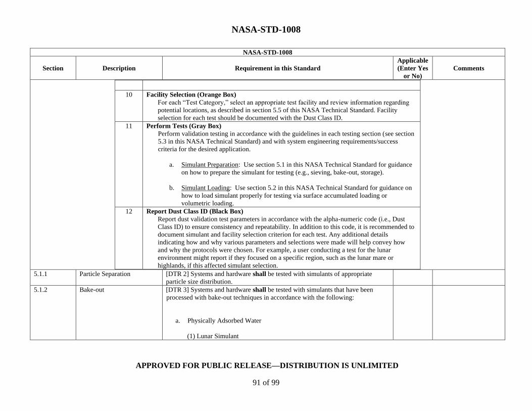
NASA-STD-1008
APPROVED FOR PUBLIC RELEASE—DISTRIBUTION IS UNLIMITED
91 of 99
NASA-STD-1008
Section Description Requirement in this Standard
Applicable
(Enter Yes
or No)
Comments
10 Facility Selection (Orange Box)
For each “Test Category,” select an appropriate test facility and review information regarding
potential locations, as described in section 5.5 of this NASA Technical Standard. Facility
selection for each test should be documented with the Dust Class ID.
11 Perform Tests (Gray Box)
Perform validation testing in accordance with the guidelines in each testing section (see section
5.3 in this NASA Technical Standard) and with system engineering requirements/success
criteria for the desired application.
a. Simulant Preparation: Use section 5.1 in this NASA Technical Standard for guidance
on how to prepare the simulant for testing (e.g., sieving, bake-out, storage).
b. Simulant Loading: Use section 5.2 in this NASA Technical Standard for guidance on
how to load simulant properly for testing via surface accumulated loading or
volumetric loading.
12 Report Dust Class ID (Black Box)
Report dust validation test parameters in accordance with the alpha-numeric code (i.e., Dust
Class ID) to ensure consistency and repeatability. In addition to this code, it is recommended to
document simulant and facility selection criterion for each test. Any additional details
indicating how and why various parameters and selections were made will help convey how
and why the protocols were chosen. For example, a user conducting a test for the lunar
environment might report if they focused on a specific region, such as the lunar mare or
highlands, if this affected simulant selection.
5.1.1 Particle Separation [DTR 2] Systems and hardware shall be tested with simulants of appropriate
particle size distribution.
5.1.2 Bake-out [DTR 3] Systems and hardware shall be tested with simulants that have been
processed with bake-out techniques in accordance with the following:
a. Physically Adsorbed Water
(1) Lunar Simulant

NASA-STD-1008
APPROVED FOR PUBLIC RELEASE—DISTRIBUTION IS UNLIMITED
92 of 99
NASA-STD-1008
Section Description Requirement in this Standard
Applicable
(Enter Yes
or No)
Comments
Heat the simulant at 110ºC (230ºF) for at least 12 hours.
b. Surface-Bound Water
(1) Lunar Simulant
Heat the simulant at 200°C (392°F) for 24 hours to release the
surface-bound water; after this, keep it hermetically sealed as
practical or re-bake before using.
c. Structural Water
(1) Lunar Simulant
Permanently remove structural water by heating sufficiently to force
re-crystallization of the relevant mineral’s dehydrated form.
5.1.3 Storage [DTR 4] Systems and hardware shall be tested with simulants that have been
stored in conditions that prevent alteration of the simulant from environmental
variations in accordance with the following:
a. Cover stored simulant (indoor storage is preferred to ensure stable
environmental conditions (e.g., temperature, humidity) to prevent debris entry,
where sealed containers that prevent moisture entry are highly recommended.
b. Use sealed hard containers with neutral (non-reactive) surfaces, e.g., paint
cans or 5-gallon buckets are preferred to bags, with additional precautions such as
plastic wrap around the seals, O-ring-type lids, and/or a layer of aluminum foil on
top of the simulant to maintain simulant conditions
c. Minimalize moisture levels for storage to prevent promotion of rust or
biologic activity.

NASA-STD-1008
APPROVED FOR PUBLIC RELEASE—DISTRIBUTION IS UNLIMITED
93 of 99
NASA-STD-1008
Section Description Requirement in this Standard
Applicable
(Enter Yes
or No)
Comments
5.3 Testing Practices and
Categories
[DTR 5] For safety while testing systems and hardware exposed to dust, test
personnel shall refer to simulant material safety data sheet warnings, ensure use of
appropriate PPE, and implement safety precautions in the test-specific procedures.
5.3.1 Aerosol Ingestion Testing [DTR 6] Systems and hardware operating in locations susceptible to aerosolized
dust ingestion shall undergo aerosol ingestion testing with simulants
representative of the dust environment in accordance with the following
methodologies:
a. Purge chamber with filtered air to achieve baseline “clean” chamber
(<20 particles/cm3 for cleanest environment categories, <0.1 mg/m3 for heavy
concentration environments[1]).
b. Aerosolize dust simulant using a powder/dust disperser or equivalent
technology.
c. Ensure a full characterization of the chamber dust environment for
test reliability and repeatability:
(1) Consistent dust concentration over test duration.
(2) Uniformity of dust dispersion throughout chamber.
5.3.2 Abrasion Testing [DTR 7] Systems and hardware susceptible to dust contact and abrasion shall
undergo abrasion testing by choosing the testing instrument and method depending
upon the specific character of the testing desired using simulants representative of
the dust environment.
5.3.3 Optical Testing [DTR 8] Systems and hardware based on optical properties (e.g., solar panels,
viewports, and camera lenses) shall undergo optical testing over the relevant range
[1] The choice of units comes from differing standards and techniques to measure clean versus heavily contaminated spaces, as well as instrument considerations
and how quickly number concentration and mass concentration can diverge, since mass scales with particle diameter cubed and depends on bulk material density.
Clean environments are typically measured with an optical particle counter or similar, which commonly report particles per unit volume (see ISO 14644-1, parts
1, 2 and 3). This technique is unsuitable for measuring a contaminated space, and a mass-based approach is preferred since a threshold mass loading can easily be
exceeded by a few large particles, which would be reported as a low particle count.
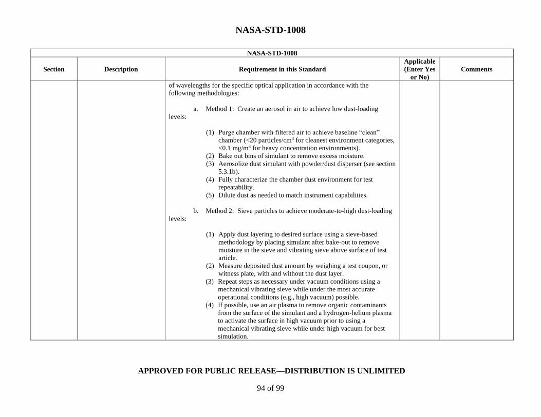
NASA-STD-1008
APPROVED FOR PUBLIC RELEASE—DISTRIBUTION IS UNLIMITED
94 of 99
NASA-STD-1008
Section Description Requirement in this Standard
Applicable
(Enter Yes
or No)
Comments
of wavelengths for the specific optical application in accordance with the
following methodologies:
a. Method 1: Create an aerosol in air to achieve low dust-loading
levels:
(1) Purge chamber with filtered air to achieve baseline “clean”
chamber (<20 particles/cm3 for cleanest environment categories,
<0.1 mg/m3 for heavy concentration environments).
(2) Bake out bins of simulant to remove excess moisture.
(3) Aerosolize dust simulant with powder/dust disperser (see section
5.3.1b).
(4) Fully characterize the chamber dust environment for test
repeatability.
(5) Dilute dust as needed to match instrument capabilities.
b. Method 2: Sieve particles to achieve moderate-to-high dust-loading
levels:
(1) Apply dust layering to desired surface using a sieve-based
methodology by placing simulant after bake-out to remove
moisture in the sieve and vibrating sieve above surface of test
article.
(2) Measure deposited dust amount by weighing a test coupon, or
witness plate, with and without the dust layer.
(3) Repeat steps as necessary under vacuum conditions using a
mechanical vibrating sieve while under the most accurate
operational conditions (e.g., high vacuum) possible.
(4) If possible, use an air plasma to remove organic contaminants
from the surface of the simulant and a hydrogen-helium plasma
to activate the surface in high vacuum prior to using a
mechanical vibrating sieve while under high vacuum for best
simulation.

NASA-STD-1008
APPROVED FOR PUBLIC RELEASE—DISTRIBUTION IS UNLIMITED
95 of 99
NASA-STD-1008
Section Description Requirement in this Standard
Applicable
(Enter Yes
or No)
Comments
(5) Once target dust layering is achieved, monitor and record key
performance parameters of the optical system (e.g., solar panel,
camera lens).
5.3.4 Thermal Testing [DTR 9] Systems and hardware susceptible to thermal variations or regulation
shall undergo thermal testing in accordance with the following methodologies:
a. Evaluate this if the system being tested will create a local pressure
that is different from the environment (e.g., a partially contained vessel with a gas
flow).
b. Position heat/cold sources relative to anticipated hardware
configuration to the extent possible.
c. Refer to figures of merit in NASA/TM-2010-216443, Figure of Merit
Characteristics Compared to Engineering Parameters.
d. Adhere to systems engineering requirements for the given
application for validating hardware against the appropriate safety factors.
e. For heat/cold sources, use isothermal with a verifiable temperature
for radiative sinks/sources.
f. For instrumentation, ensure all instruments have a verifiable and
current calibration:
(1) Direct Temperature (thermocouples, resistance temperature
detectors [RTDs]).
(2) Indirect Temperature (pyrometers, thermal imagers).
5.3.5 Mechanisms Testing [DTR 10] Systems and hardware susceptible to mechanical dust interference shall
undergo mechanisms testing in accordance with the following methodologies:

NASA-STD-1008
APPROVED FOR PUBLIC RELEASE—DISTRIBUTION IS UNLIMITED
96 of 99
NASA-STD-1008
Section Description Requirement in this Standard
Applicable
(Enter Yes
or No)
Comments
a. Method 1: Friction and Wear Testing – Component:
(1) Apply dust-loaded grease or lubricant to the tribological
component.
(2) Apply the grease or lubricant with various types of motion (e.g.,
vertical, linear, rotational, reciprocating) combined with a
determined load on the test hardware/system.
b. Method 2: Infiltration Testing – System:
(1) Load hardware/systems on a dynamometer with appropriate
speed and torque-sensing capabilities.
(2) Install thermal straps between the test article and cooling system
for thermal vacuum environments.
(3) Perform testing in an enclosure with controlled dust dispersion.
5.3.6 Seals and Mating Surfaces
Testing
[DTR 11] Systems and hardware with seals or mating surfaces susceptible to dust
contamination shall undergo seals and mating surfaces testing in accordance with
the following methodologies:
a. Install the operational seal hardware/system in the test fixture in
which dust exposure is expected to occur. Depending on the operational
configuration, the sealing interface could be open (e.g., hatch, sample container)
or closed (e.g., space suit joint).
b. Insert the hardware/system into the dust application chamber or
device.
c. Apply dust to the desired surface(s).
d. Accomplish dust deposition by recirculating the dust in an enclosed
volume or applying through a sieve.

NASA-STD-1008
APPROVED FOR PUBLIC RELEASE—DISTRIBUTION IS UNLIMITED
97 of 99
NASA-STD-1008
Section Description Requirement in this Standard
Applicable
(Enter Yes
or No)
Comments
e. If the sealing interface was open during dust application, close the
interface to the operational configuration where it is expected to maintain a seal
(i.e., pressure differential).
f. If leak tests are to be performed under specific thermal conditions,
install the test fixture in an environmental chamber.
g. Perform leak tests to evaluate the sealing performance and assess
potential degradation.
h. When applicable, repeat the exposure to the dust environment to
simulate full operational cycles and perform additional leak tests between
exposures to evaluate potential effects of dust accumulation.
5.3.7 Reactivity Testing [DTR 12] Systems and hardware susceptible to the reactivity of dust particles
shall undergo reactivity testing in accordance with the following:
a. Method 1: Electrical Activation
Use plasma treatment to alter the surface chemistry of the material.
b. Method 2: Mechanical Activation
(1) Use the ball milling procedure as follows:
A. Add a pre-determined amount of quartz or lunar simulant
into a mixing bowl.
B. Program rotation rate (i.e., impact energy) and milling time
to pre-determined parameters to achieve desired
properties/reactivities.
(2) Use the grinding with mortar and pestle procedure to
mechanically activate simulant as follows:

NASA-STD-1008
APPROVED FOR PUBLIC RELEASE—DISTRIBUTION IS UNLIMITED
98 of 99
NASA-STD-1008
Section Description Requirement in this Standard
Applicable
(Enter Yes
or No)
Comments
A. Add an appropriate amount of quartz or lunar simulant in a
mortar and grind with a pestle for 10 minutes, stopping
every 2 minutes to scrape the sides to ensure even grinding.
B. Start with the same amount of material for every test, as
grinding different amounts can lead to different reactivities.
c. Method 3: Chemical Activation
Use a mortar and pestle procedure as follows:
(1) Mix M1300 (Cabot Corporation) or arc soot with simulant using
mortar and pestle.
(2) Use 0.5, then 1.0 and 5.0 wt% of carbon to oxide simulant.
(3) Use an amount of simulant appropriate for the test being
conducted.
(4) Perform thermogravimetric analysis (TGA); purge well.
(5) Heat to ~1000°C (1832°F) using a constant temperature ramp,
under inert atmosphere.
(6) Cool to room temperature, under inert atmosphere.
(7) Switch to air and measure the weight change as a function of a
moderate-to-slow temperature ramp (e.g., <20°C/min (<68°F),
perhaps 10°C/min (50°F).
5.3.8 Electrostatic Properties [DTR 13] Systems and hardware susceptible to electrostatic dust contamination or
interference shall undergo electrostatics testing in accordance with the following
methodologies:
a. Measurement Method
(1) Volume Resistivity Testing:
A. Place the sample between two electrodes, applying a known
voltage, and monitoring the resulting current.

NASA-STD-1008
APPROVED FOR PUBLIC RELEASE—DISTRIBUTION IS UNLIMITED
99 of 99
NASA-STD-1008
Section Description Requirement in this Standard
Applicable
(Enter Yes
or No)
Comments
B. Calculate the volume resistivity by multiplying the ratio of
the voltage to current times the ratio of the area of the
electrode over the sample thickness.
b. Method 1: Triboelectric Charge Generation
(1) Use highly resistive simulants to determine effect of regolith on
the component or system for hardware/system(s) that are
concerned with dust adherence and/or charge buildup on
surfaces.
(2) Simulate charge-to-mass levels by sieving, shaking, or pouring
particles under the following test conditions.
(3) For other charge generation methods, perform testing to estimate
the charge-to-mass values expected (e.g., plume effects).
c. Method 2: Electrical Arcing
For hardware/system(s) that are susceptible to electrical arcing or surface
discharges, pre-charge dust simulants using methods described in ISO
11221:2011, Space systems – Space solar panels – Spacecraft charging induced
electrostatic discharge test methods.
5.3.9 Plume Surface Interaction
Testing
[DTR 14] Systems and hardware susceptible to effects from PSI shall undergo
plume surface interaction testing to mimic the effect of dust impingement on
vehicle surfaces by considering and replicating, as feasible, the environment and
mode of dust interaction.
Recommended