CISCO SERVICE CONTROL SOLUTION GUIDE
Cisco Service Control Product Installation Guide1 Overview
2 Cisco Service Control Topology
3 System Installation
4 Initial Configuration
5 Cisco SCE 2000 Platform Installation
6 System Requirements and Prerequisites
7 Obtaining Documentation and Submitting a Service Request
Revised: January 25, 2011, OL-18872-01
1 OverviewThis overview introduces the components of the Cisco Service Control solution and gives a high-level explanation of the total installation process.
System ComponentsThe Cisco Service Control solution consists of five main components:
• The Service Control Engine (SCE) platform: A flexible and powerful dedicated network-usage monitor that is purpose-built to analyze and report on network transactions at the application level.
For complete information regarding the installation and initial configuration of the SCE platform, see the Cisco SCE Platform Installation and Configuration Guides.
• The Service Control Application for Broadband (SCA BB): An application that creates a service configuration file containing settings for traffic classification, accounting and reporting, and applies it to an SCE platform. It provides tools to automate the distribution of these configuration files to SCE platforms. This simple, standards-based approach makes it easy to manage multiple devices in a large network.
For complete information regarding the installation and operation of SCA BB, see the Cisco Service Control Application for Broadband (SCA BB) User Guide.
• The Service Control Management Suite (SCMS) Subscriber Manager (SM): A middleware software component used where dynamic binding of subscriber information and policies is required. The SM manages subscriber information and provisions it in real time to multiple SCE platforms. The SM can store subscriber policy information internally, and act as a stateful bridge between the AAA system (such as Radius and DHCP) and the SCE platforms.
For complete information regarding the installation and operation of the SM, see the Cisco Service Control Management Suite Subscriber Manager User Guide.
The Quota Manager (QM) is an optional component of the Subscriber Manager. It enables Service Control solution providers to manage subscriber quota across subscriber sessions with a high degree of flexibility.
For complete information regarding the installation and operation of the QM, see the Cisco Service Control Management Suite Quota Manager Solution Guide.
The Virtual Link Manager (VLM) is a component of the Subscriber Manager that enables Service Control solution providers to monitor and control individual subscriber links separately by creating a single policy that contains the tier differentiated packages, creating a number of virtual links and then assigning subscribers to the virtual links. For full details, see the Cisco Service Control for Managing Remote Cable MSO Links Solution Guide.
• The Service Control Management Suite (SCMS) Collection Manager (CM): An implementation of a collection system that receives Raw Data Records (RDRs) from one or more SCE platforms. It collects usage information and statistics, and stores them in a database. The CM also converts subscriber usage information and statistics into simple text-based files for further processing and collection by external systems.
For complete information regarding the installation and operation of the CM, see the Cisco Service Control Management Suite Collection Manager User Guide.
• The Service Control Application (SCA) Reporter-A software component that processes data stored by the CM and provides a set of insightful reports from this data. The SCA Reporter can run as a standalone or as an integrated part of the Console.
For complete information regarding the installation and operation of the Reporter, see the Cisco SCA BB Reporter User Guide.
Together, the SCE platform, the SCMS-CM, the SCMS-SM, and the SCA Reporter are designed to support detailed classification, analysis, reporting, and control of IP network traffic. The SCMS-CM, the SCA Reporter, and the SCMS-SM are optional components; not all deployments of the Cisco Service Control solution require them. Sites that employ third-party collection and reporting applications, those that do not require dynamic subscriber-aware processing, and those that use a Radius or DHCP sniffing option may not require all of these components.
2
Options and Versions
The Cisco SCE Platform
The Cisco SCE platform is available in three versions:
• SCE 1000: with two GBE interfaces, supporting one traffic link
• SCE 2000 4 xGBE: with four GBE interfaces, supporting two traffic links and cascaded topology.
• SCE8000: with two or four 10 GBE interfaces. Four interfaces support two traffic links and cascaded topology.
All platform versions are available with either AC or DC power.
Note In general, this guide contains instructions for installing the Cisco SCE8000 platform.
The SCA BB Application
SCA BB is not available in different versions.
Subscriber Manager (SM)
The SM is available in the following versions:
• Solaris
• Linux
Both SM versions are available with the following options:
• Optional Veritas cluster support for redundancy
• Optional Login Event Generators (LEGs)
Collection Manager (CM)
The CM is available in the following versions:
• Solaris
• Linux
Both CM versions are available with either of the following options:
• Uses the bundled database (Sybase Adaptive Server Enterprise database)
• Uses an external database (Any JDBC-compliant database, such as Oracle™ or MySQL, used in conjunction with the JDBC Adapter)
Reporter
The Reporter does not come in different versions.
3

System Installation OverviewThe following figure shows the order of installing the components of the Cisco Service Control system
Figure 1 Installing the Complete Cisco Service Control Product
To install the complete Cisco Service Control system, complete the following steps:
Step 1 Install the SCE platform (see Installing the SCE8000 Platform, page 10).
This includes:
• Installation in the rack
• Initial configuration using a local console
• Cabling management and line ports
Step 2 Install the Subscriber Manager (see Installing the Subscriber Manager, page 12).
This includes:
• Preliminary configuration (memory settings and configuration file.)
• Installing the SM software
• Adding a user for PRPC authentication
Step 3 Install the Connection Manager (see Installing the Collection Manager, page 14).
This includes:
• If using the bundled database: Installing the bundled database
• Installing the CM software
• Configuration related to the various adapters
• Adding a user for PRPC authentication
• If using an external database (unbundled): Configuring the CM to be able to connect to the database
Step 4 Install the SCA BB console and optional SCA BB configuration utilities (see Installing the SCA BB Application, page 17).
Step 5 Install the SCA BB application component (pqi file) and protocol pack on the SCE platform (see Installing the Application and Protocol Pack on the SCE Platform, page 18.)
Step 6 Perform any additional initial configuration of the Cisco SCE8000 platform from the management work station (see Initial Configuration of the Cisco SCE8000 Platform, page 26).
LINK RX
Cisco SCE 2000 Series4xGBE
TX
RX MM TX
LINK RX TX
RX MM TX
LINK RX TX
RX MM TX
LINK RX TX
RX MM TX
GBE-1SUB LINE NET
PWR B STATUS
PWR ABYPASS
10/100/1000
LINK/ACTIVE 10/100/
1000
LINK/ACTIVE
GBE-2SUB LINE/CASCADE NET
AUXCONSOLE
MNG 2MNG 1
2741
76
SCE platform
RDRs
CLI andSNMP XML/RPC
Subscriber info
SubscriberManager
SCA BB applicationService policy andquota management
Networkmanagement
CollectionManager
1
23
4
4

Step 7 Perform initial configuration of the SCA BB application using the Usage Analysis Wizard (see Initial SCA BB Configuration, page 27).
2 Cisco Service Control TopologyThis chapter describes the possible deployment topologies of the Cisco Service Control Solution.
Note This chapter presents the deployment topologies for the Cisco SCE8000 platform. For information regarding the deployment topologies for the Cisco SCE 2000 platform, see Cisco SCE 2000 Platform Installation, page 39
Overall System TopologyFigure 2 illustrates the general topology of the Cisco Service Control solution.
• Horizontal flow—Represents traffic between subscribers and an IP network.
The SCE platform monitors traffic flow.
• Vertical flow—Represents transmission of the Raw Data Records (RDRs) from the SCE platform to the CM.
The SM provides subscriber data. This allows SCA BB to conduct subscriber-level analysis and control.
Figure 2 Flow of Information in SCA BB
Cisco SCE8000 Platform TopologiesThe Cisco SCE8000 is a solution for dual links with load sharing and asymmetrical routing and support for fail-over between two SCE platforms.
The Cisco SCE8000 is built to support wire speed processing of full-duplex 10GBE streams. The Cisco SCE8000 can, therefore, be deployed in a multi-link environment, in several different topologies.
9281
8
LINK RX
Cisco SCE 2000 Series4xGBE
TX
RX MM TX
LINK RX TX
RX MM TX
LINK RX TX
RX MM TX
LINK RX TX
RX MM TX
GBE-1SUB LINE NET
PWR B STATUS
PWR ABYPASS
10/100/1000
LINK/ACTIVE 10/100/
1000
LINK/ACTIVE
GBE-2SUB LINE/CASCADE NET
AUXCONSOLE
MNG 2MNG 1
Aggregationdevice
(CMTS,BRAS,switch, etc.)
RADIUS/DHCP
Router/Switch
Router/Switch
Service ControlSubscriber Manager
Service ControlCollection Manager
Subscriberprovisioning
Usage informationand statistics
Login/Logout
Broadbandsubscribers Internet
5

• Single Cisco SCE8000 topology — Provides the ability to process both directions of a bi-directional flow, processing both the upstream and downstream paths of a flow, even if they traverse different links.
• Dual Cisco SCE8000 topology (cascade) — Cascaded Cisco SCE8000s provide high-availability and fail-over solution and maintain the line and service in case of Cisco SCE8000 failure
• Multi-Gigabit Service Control Platform (MGSCP) topology — For scalability, the Cisco SCE8000 platform supports the option to connect a multiple number of SCE platforms to a Cisco 7600 Series router used to perform load-balancing between the platforms.
Physical Topologies
Following are descriptions of a number of physical topologies that the Cisco SCE8000 supports.
• Single Cisco SCE8000 Topologies, page 6
• Single Cisco SCE8000 Topologies, page 6
• Dual Cisco SCE8000 Topology (Cascade), page 8
• Multi-Gigabit Service Control Platform (MGSCP) Topology, page 9
Single Cisco SCE8000 Topologies
A single Cisco SCE8000 supports both single 10GBE link and dual 10GBE link topologies.
• Single Link: Inline Topology, page 6
• Dual link: Inline Installation, page 6
• Single Link: Receive-only Topology, page 7
• Dual Link: Receive-Only Topology, page 8
Single Link: Inline Topology
Typically, the Cisco SCE8000 is connected in a full duplex 10GBE link between two devices (Router, BRAS, etc.). When the Cisco SCE8000 is installed as an inline installation, it physically resides on the data link between the subscribers and the network.
Figure 3 Single Link: Inline Topology
Dual link: Inline Installation
In this topology, one Cisco SCE8000 is connected inline in two full duplex, 10GBE links.
In case the two links are load-shared, asymmetrical routing might occur, and some of the flows may be split, that is, the upstream packets of the flow go on one link, and the downstream packets go on the other link.
When installed in this topology, the Cisco SCE8000 completely overcomes this phenomenon, and provides its normal functionality as if asymmetrical routing were not occurring in the two links.
Subscriber
2705
88Network3/0/0
3/2/0
3/1/0
3/3/0
6

Figure 4 Dual link: Inline Installation
Single Link: Receive-only Topology
In this topology, an optical splitter resides physically on the 10GBE link between the subscribers and the network. The traffic passes through the optical splitter, which splits traffic to the Cisco SCE8000. The Cisco SCE8000, therefore, only receives traffic and does not transmit.
Figure 5 Single Link: Receive-only Topology
In an optical splitter topology, the Cisco SCE8000 only enables traffic monitoring functionality.
Note When implementing receive-only topologies with a switch, the switch must support SPAN functionality that includes separation between ingress and egress traffic and multiple SPAN-ports destinations.
Subscriber 1
2705
89
Network 13/0/0
3/2/0
3/1/0
3/3/0
Subscriber 2
Network 2
SplitterSubscriber
2705
86Network
3/0/0
3/2/0
3/1/0
3/3/0
7

Dual Link: Receive-Only Topology
In this topology, one Cisco SCE8000 is connected in receive-only mode to two full duplex, 10 GBE links using optical splitters.
As with the dual link, inline topology, this topology completely overcomes the problem of asymmetrical routing.
Figure 6 Dual Link: Receive-Only Topology
Note When implementing receive-only topologies with a switch, the switch must support SPAN functionality that includes separation between ingress and egress traffic and multiple SPAN-ports destinations.
Dual Cisco SCE8000 Topology (Cascade)
In this topology, two cascaded Cisco SCE8000s are used. This allows a fail-over solution, where in case of a failure of one Cisco SCE8000 the functionality that the Cisco SCE8000 provides is preserved by the redundant platform.
This topology allows both control and monitoring functionality where redundancy is required and “inline” connection is used. The two Cisco SCE8000s are cascaded, so the primary Cisco SCE8000 processes the traffic of the two links, while the secondary Cisco SCE8000 only bypasses the traffic of its links to the primary Cisco SCE8000 for processing, and then bypasses the processed traffic back to the link. The two Cisco SCE8000s also exchange keep-alive messages and subscriber state information.
In case the primary Cisco SCE8000 fails, the two Cisco SCE8000s switch their roles, and this way fail-over is provided.
Figure 7 Two Cascaded Cisco SCE8000 Platforms
This fail-over solution preserves the Cisco SCE8000 functionality and the network link:
• The two Cisco SCE8000s are simultaneously aware of the subscriber contexts, and subscriber states are constantly exchanged between them, such that if the primary Cisco SCE8000 fails, the secondary can take over with minimum state loss.
2705
87
Subscriber 1
Network 1
Subscriber 2
Network 2
3/0/0
3/2/0 3/3/0
3/1/0
Splitter
Splitter
Subscriber
2705
90
Network3/0/0
3/2/0
3/1/0
3/3/0
Subscriber
Network
3/2/0
3/0/0
3/3/0
3/1/0
8

• When one Cisco SCE8000 fails (depending on the type of failure) its link traffic is still bypassed to the functioning Cisco SCE8000 and processed there, so the traffic processing continues for both the links.
• The bypass of the traffic through the failed Cisco SCE8000 is configurable, and the user may choose to always cutoff the line that goes through the failed Cisco SCE8000. In this case network redundancy protocols like HSRP are responsible for identifying the line cutoff and switching all the traffic to go through the functioning Cisco SCE8000.
• In addition, it is possible to configure the Cisco SCE8000 to use the external optical bypass device so that in the event of any failure of the Cisco SCE8000, it will be used to provide link continuity. This ensures 100% link continuity at the expense of providing asymmetric routing functionality.
Multi-Gigabit Service Control Platform (MGSCP) Topology
In this topology, multiple Cisco SCE8000 platforms are connected to a Cisco 7600 Series router, which acts as a dispatcher between the platforms. The router contains two EtherChannels (ECs), one for the subscriber side and one for the network side, that perform load balancing for the SCE platform traffic. Traffic enters the first router, is distributed between the SCE platforms by the subscriber-side EC and then returns to the router so it can be forwarded to its original destination.
Figure 8 Basic MGSCP Topology
There are a number of variables to be considered in the MGSCP topology. Two of the main factors to be considered include:
• Type of SCE Platform Redundancy, page 9
• Redundant Cisco 7600 Series Router, page 10
Type of SCE Platform Redundancy
• All Active
All ports in the EC and all SCE platforms are active. If there is a failure in one of the SCE platforms, the links on the related ports in the EC will be down and the EC will automatically exclude it from the load distribution. The load will then be distributed between the remaining active SCE platforms.
Since the Cisco SCE8000 supports two links, this configuration requires one SCE platform per two links (two EC ports).
• N+1
'N' SCE platforms are active and one platform is on standby. The EC ports connected to the standby SCE platform must be configured as standby ports. In the case of failure of one of the SCE platforms, the EC ports connected to the failing SCE platform are shut and the standby EC ports, connected to the standby SCE platform, will be activated.
Since the Cisco SCE8000 supports two links, this configuration requires one SCE platform per two links (two EC ports), plus one extra SCE platform for standby.
4+1SCE8000s
2708
77
Cisco 7600 40GigSubscribers
Internet
9

Note that the standby SCE platform must be connected to the two highest-numbered ports, since EC behavior automatically designates these as the standby ports.
Redundant Cisco 7600 Series Router
Two Cisco 7600 Series routers can be used to provide network redundancy.
In this topology, one link on each Cisco SCE8000 platform is connected to each router. Therefore, one SCE platform is required for each link.
Figure 9 MGSCP with Redundant Router
3 System Installation
Installing the SCE8000 PlatformTo install a Cisco SCE8000 platform, complete the following steps. (For more information, refer to the Cisco SCE8000 Installation and Configuration Guide.)
Note For information on installing an SCE 2000 platform, see Installing a Cisco SCE 2000 Platform, page 42.
Step 1 Install the SCE platform in the rack.
Step 2 Connect the chassis ground and the power.
Step 3 Connect the CON port to a local terminal. Configure the initial setup parameters as necessary. (See Initial Configuration of the Cisco SCE8000 Platform, page 26)
Step 4 Connect the MNG port to the local LAN.
Step 5 Cable the line ports. (See SCE8000 Connectivity, page 11 for a summary of proper cabling for various topologies)
Internet4+1SCE8000s
2708
83
40Gig
40Gig
Subscribers
Cisco 7600
Cisco 7600
10

SCE8000 Connectivity
The following tables summarize SCE8000 connectivity for the basic topologies.
Receive-only topologies use only Receive fibers.
Note Receive-only topologies can be implemented using either an optical splitter or a switch. If a switch is used, it must support SPAN functionality that includes separation between ingress and egress traffic and multiple SPAN-ports destinations.
Table 1 Single link inline connectivity
Table 2 Dual link inline connectivity
Table 3 Cascade connectivity
Table 4 Optical Bypass connectivity: Single link
Port Link Side
3/0/0 Link 0 Subscribers
3/1/0 Link 0 Network
Port Link Side
3/0/0 Link 0 Subscribers
3/1/0 Link 0 Network
3/2/0 Link 10 Subscribers
3/3/0 Link 1 Network
This port on SCE8000 #1 Connects to this...
3/0/0 Subscriber side network element
3/1/0 Network side network element
3/2/0 (cascade port) port 3/3/0 on SCE8000 #2
3/3/0 (cascade port) port 3/2/0 on SCE8000 #2
This port on SCE8000 #2 Connects to this....
3/0/0 Subscriber side network element
3/1/0 Network side network element
3/2/0 (cascade port) port 3/3/0 on SCE8000 #1
3/3/0 (cascade port) port 3/2/0 on SCE8000 #1
This optical bypass port Connects to this...
A Subscriber side network element
B Network side network element
C SCE platform port 3/0/0
D SCE platform port 3/1/0
CTRL left-hand 'External Bypass' port on SCE8000-SCM-E module.
11

Table 5 Optical Bypass connectivity: Dual link
Multi-Gigabit Service Control Platforms (MGSCP) Topologies
In an MGSCP deployment, the exact cabling scheme depends on the number and arrangement of ports in the EtherChannel in the Cisco 7600 Series router. It is therefore not possible to give exact cabling schemes. Refer to the following general guidelines when designing the cabling scheme.
General guidelines for MGSCP topologies:• Since there are two links per Cisco SCE8000 platform, the minimum number of platforms required is half the number of
links used.
• Each link corresponds to one port on the EtherChannel (EC) on the Cisco 7600 Series router. Each EC supports a maximum of eight ports. Therefore, if all eight EC ports are configured, four Cisco SCE8000 platforms are required.
• For N+1 redundancy, two ports (connected to the standby platform) must be configured as standby ports on both ECs.
• Therefore, for N+1 redundancy, one router and five Cisco SCE8000 platforms would be used to support eight links.
• If two Cisco 7600 Series routers are used (for network redundancy), one link on each Cisco SCE8000 platform is connected to each router. This requires twice the number of Cisco SCE8000 platforms, one platform for each link.
– A minimum of eight Cisco SCE8000 platforms are required to support eight ports.
– For N+1 redundancy, nine Cisco SCE8000 platforms would be used to support eight active links.
When cabling to the EC, follow these guidelines:
• The Cisco SCE platform ports MUST be connected to the EC ports in the same order on both sides.
• The EC ports should be sorted in an ascending order by their physical interface numbers.
• In a topology with two Cisco 7600 Series routers, the order of connection to the EC ports must be the same on both routers. In order for both routers to send the traffic of a given subscriber to the same SCE platform, the SCE platforms must be connected to both routers in exactly the same order (one SCE platform connected to the first link on both routers, another SCE platform connected to the second link on both routers, and so on).
Installing the Subscriber ManagerThis section describes how to install SM Version 3.5.0 or later on a computer running Solaris or Red Hat Linux.
For more information, refer to the Cisco SCMS Subscriber Manager User Guide.
Step 1 Use FTP to load the distribution files to the SM and extract them.
Step 2 Determine the system memory settings.
This port on optical bypass #1 Connects to this...
A Subscriber side network element
B Network side network element
C SCE platform port 3/0/0
D SCE platform port 3/1/0
CTRL left-hand 'External Bypass' port on SCE8000-SCM-E module.
This port on optical bypass #2 Connects to this...
A Subscriber side network element
B Network side network element
C SCE platform port 3/2/0
D SCE platform port 3/3/0
CTRL right-hand 'External Bypass' port on SCE8000-SCM-E module.
12

Set the system memory configuration requirements according to the maximum number of subscribers. See the Cisco Service Control Management Suite Subscriber Manager User Guide, the Installation and Upgrading chapter, the “Installation Procedure” section.
Step 3 Configure the shared memory settings.
TimesTen requires that certain changes be made in the operating system kernel configuration file:
• For Solaris, modify file /etc/system.
• For Linux, modify file /etc/sysctl.conf.
These changes increase the shared memory and semaphore resources on the machine from their defaults. See the Cisco Service Control Management Suite Subscriber Manager User Guide, the Installation and Upgrading chapter, the “Installation Procedure” section.
Step 4 Edit the install-def.cfg file.
Note This step is optional when performing the SM installation. However, it is recommended to edit the file if one of the parameter values should not be set to the default value.
The install-def.cfg file contains several parameters that can be preconfigured before installation of the SM. These parameters are copied by the install routine to the relevant SM configuration files. By default, all of the parameters are commented out and the default values are used.
The file contains the following parameters:
Step 5 Execute the install-sm.sh script.
Note The install-sm.sh script is customizable.
Note It is not possible to run the script if the /etc/motd file exists. The file should be moved or removed prior to running the install-sm.sh script.
From your workstation shell prompt, move to the directory to where the distribution file was extracted and run the install-sm.sh script. See the Cisco Service Control Management Suite Subscriber Manager User Guide, the Installation and Upgrading chapter, the “Installation Procedure” section.
Step 6 Set the password for the pcube user
Parameter Name Resides in Description Alternate configuration option
max_subscribers_num SM Definitions Defines the maximum number of subscribers the SM support
Maximum:
• Solaris 20 million
• Linux two million
Default: 200,000
max_number_of_subscribers parameter in p3sm.cfg configuration file
sm_memory_size SM Definitions Defines the amount of memory allocated for the SM process in MB
PCUBE_SM_MEM_SIZE in the sm.sh file that resides under the ~pcube folder.
database_perm_size Database Definitions
Defines the PermSize allocated for the database in MB
PermSize parameter in the /var/TimesTen/sys.odbc.ini file
database_temp_size Database Definitions
Defines the TempSize allocated for the database in MB
TempSize parameter in the /var/TimesTen/sys.odbc.ini file
13

After the installation script has completed successfully, set the password for the pcube user by running the # passwd pcube command.
Note It is important to remember the password you have selected.
Step 7 Reboot the computer.
It is necessary to reboot the computer to complete the installation.
Step 8 Add a user for PRPC authentication.
It is necessary to add a user for PRPC authentication because SCA BB requires a username and password when connecting to the SM.
To add a user for PRPC authentication, use the p3rpc command-line utility. For example:
>p3rpc --set-user --username=pcube --password=pcube-password
Installing the Collection ManagerThis section describes how to install the Collection Manager, either with the bundled Sybase database or unbundled, on a computer running Solaris or Red Hat Linux.
• Ports Used by the Collection Manager Software, page 14
• Installing the Sybase Database, page 15
• Installing Collection Manager Software, page 15
For more information, refer to the Cisco SCMS Collection Manager User Guide.
Ports Used by the Collection Manager Software
Table 6 describes the TCP/UDP ports on which the CM software and associated components (such as the Sybase database) listen. This table may help the network administrator understand the behavior of the software and its adherence to the security policy.
Table 6 Ports that the CM Listens on Constantly
Port Number Description
33000 Used by the SCE devices to send RDRs for data collection.
21 Used by the legacy (pre-Version 3.0) SCAS Reporter to authenticate against the CM user on the CM machine.
33001 Internal collection manager.
Note Access is required only from the local machine; external access can be blocked.
9092 HTTP technician interface.
4100 (For installations with bundled Sybase) Sybase database connectivity through ODBC/JDBC. Required for access to the database.
1099—1120 RMI. Used as the management interface between the data collector and the Service Control management server.
22000 FTP server of the CM.
Note FTP transactions may listen on other ports (22001 to 22100) for data transfer, as negotiated by the protocol.
7787 Internal logging of the management user log.
Note Access is required only from the local machine; external access can be blocked.
14375 Used by the Cisco Service Control Application Suite for Broadband (SCA BB) Console to send symbol definitions (values.ini) to the CM.
14

The ports listed are those on which the device listens constantly. You should allow access on these port numbers; otherwise, certain operations may fail.
Some operations (such as file transfer) cause a device to temporarily open ports other than those listed; however, these ports close automatically when the operation ends.
Installing the Sybase Database
If you do not want to install Sybase (for example, when working in unbundled mode), go to Installing Collection Manager Software, page 15.
Note Installing the Sybase database can take up to three hours.
Note When using the bundled Sybase database, the server on which you install the CM can have a maximum of 4 CPU cores.
Note The maximum database size supported by the bundled Sybase database is 50GB. For database support larger than 50GB, use an external database.
The installsyb.sh script installs the Sybase database. For information about actions performed by the script, see the Cisco SCMS Collection Manager User Guide.
Step 1 Log in as the root user and make the distribution kit contents available on your system or local network
Step 2 Change directory to sybase in the distribution kit root.
Step 3 Run the script installsyb.sh. Enter the script as follows:
installsyb.sh --sybhome=SYBHOME {--datadir=DATADIR}
• SYBHOME is the home directory of the Sybase user (and should have 1 GB free)
• Select one of the following data location options:
– Specify --datadir=DATADIR, where DATADIR is a directory in which all Sybase data is to be stored.
Use a location in a partition where at least 15 GB is free.
• If you specify a DATADIR, all Sybase data is stored as normal files in that directory, with default sizes of 10 GB for data, 3 GB for logs, and 3 GB for Sybase temporary storage. The ownership of the directory is changed to the Sybase user during installation.
Step 4 After the script completes, set a password for the sybase user
Use the passwd command as follows:
# passwd sybase
Installing Collection Manager Software
Use the install-cm.sh script to install the collection manager server.
install-cm.sh Options The usage message for the install-cm.sh script is:
Usage: install-cm.sh [-h] (-d CMDIR | -o)
Options: -d CMDIR select directory for ~scmscm (must not exist and must be on 8 GB free partition) -o upgrade the existing installation while preserving the current configuration (can't be used with -d) -h print this help and exit
15

Description of the options:
-d CMDIR Used to designate the directory of the newly created scmscm user's home. Should be the name of a non-existing directory, whose parent resides on a partition where at least 8 GB is free. As an alternate to this option, you can specify -o :
-o Use this option when you wish to upgrade the existing installation while preserving the current configuration. (can't be used with -d)
For information about actions performed by the install-cm.sh script, see the Cisco SCMS Collection Manager User Guide.
Step 1 Change directory to install-scripts under the distribution kit root.
Step 2 Run the install-cm.sh script.
# install-cm.sh -d <CM home dir>
Step 3 After the script completes, set a password for the scmscm user.
Run the following command to set the password for the scmscm user:
passwd scmscm
Be sure to record the password that you choose.
Step 4 (Optional) To configure the CM to use an external database use the ~scmscm/scripts/dbconf.sh script.
The following is a list of supported external databases:
• Sybase—Version 12.5.1 and higher
• Oracle—Versions 9.2, 10g, and 11g
• MySQL—Version 4.1 and higher
For further information see the Cisco Service Control Management Suite Collection Manager User Guide, the “Managing the Collection Manager” chapter, the “Configuring Databases” section.
Step 5 Start the database.
If you are using an external database, start it according to the instructions supplied by the database vendor.
If you are using the Sybase database:
a. As the root user, run the sybase start command
# ~scmscm/setup/sybase start
b. Wait several minutes and run the alive.sh script
# ~scmscm/setup/alive.sh
Make sure the output does not contain the phrase "Sybase not functioning".
Step 6 Configure the adapters to use and the categorizer.
For details, see the Cisco SCMS Collection Manager User Guide, the “Configuring the CM” section.
Step 7 Start the CM by running the following command:
~scmscm/cm/bin/cm start
Step 8 Set the CM time zone using the jselect-sce-tz.sh script.
For example, if the SCE device is located in GMT+2, run the following command as the scmscm user:
$ ~scmscm/cm/bin/jselect-sce-tz.sh --offset=120
Step 9 Activate the periodic delete procedures for the database tables by running the create_periodic_del_procs.sh script as the scmscm user.
~scmscm/db_maint/create_periodic_del_procs.sh
For details, see the Cisco SCMS Collection Manager User Guide, the “Managing the Periodic Deletion of Old Records” section.
Step 10 Activate the automatic invocation of the periodic delete procedures
16

Run the following command:
$~scmscm/scripts/dbperiodic.py --load
This loads the default data retention settings defined in ~scmscm/db_maint/dbperiodic.conf.
Step 11 Add a user for PRPC authentication.
It is necessary to add a user for PRPC authentication because SCA BB requires a username and password when connecting to the CM.
To add a user for PRPC authentication, use the p3rpc command-line utility. For example:
~scmscm/cm/bin/p3rpc --set-user --username=scmscm --password=scmscm-password
Installing the SCA BB ApplicationThis section describes how to install SCA BB application.
For more information, refer to the Cisco Service Control Application for Broadband User Guide.
SUMMARY STEPS
Step 1 Verify that both the SCE platform(s) and the SM are operating and running versions that are compatible with your SCA BB version.
Step 2 Install the SCA BB console.
Step 3 (Optional) Install the SCA BB utilities:
• Service Configuration Utility (servconf)
• SCA BB Signature Configuration Utility (sigconf)
• SCA BB Real-Time Monitoring Configuration tool (rtmcmd) (together with associated real-time monitoring report templates
Step 4 Install the SCA BB application component that reside son the SCE platform. This can be done from the SCA BB console at a later stage in the overall installation process. See How to Install Files on the SCE Platform, page 19.
How to Verify that the SCE Platform is Running a Compatible Version of the OS
Step 1 At the SCE platform CLI prompt (SCE#), type show version.
Step 2 Press Enter.
The response shows the version of the OS running on the SCE platform.
How to Verify that the SM is Running a Compatible Version
Step 1 Open a Telnet session to the SM.
Step 2 Go to the SM bin directory and type p3sm version.
Step 3 Press Enter.
The response to this command displays the SM version.
17

How to Install the SCA BB Console
Step 1 Navigate to the Console installation file, sca-bb-console-<xxx>.exe, and double-click it.
A standard installer wizard appears.
Step 2 Follow the standard installation steps to install the application in the desired location.
How to Install the SCA BB Configuration Utilities
This step is optional.
Step 1 From the SCA BB installation package, extract the file scas_bb_util.tgz, and copy it to a Windows, Solaris, or Linux workstation.
Step 2 Unpack the file to a new folder.
The SCA BB Service Configuration Utility (servconf), the SCA BB Real-Time Monitoring Configuration Utility (rtmcmd) (and associated real-time monitoring report templates), and the SCA BB Signature Configuration Utility (sigconf) are located under the bin folder.
Installing the Application and Protocol Pack on the SCE PlatformUse the SCE Software Upgrade Wizard in the console to install the application file (pqi) and the protocol pack (spqi) on selected SCE platforms.
Before You Start
Before you begin the SCE platform upgrade, make sure you do the following:
• Gather the IP addresses of all SCE platforms to be upgraded. (Not necessary if they are all defined in the Network Navigator)
• Download the relevant pqi file and protocol pack to a local location or to a location accessible by FTP. If using an FTP site, make sure to have the complete FTP location and path for each file.
18

How to Install Files on the SCE Platform
Step 1 In the Network Navigator of the console, select the SCE platforms to be upgraded. Right-click and from the menu, select SCE Software Upgrade Wizard.
If the SCE platforms are not yet defined in the Network Navigator, you can select the site node.
19

The SCE Software Upgrade Wizard opens.
Step 2 In the SCE IP Addresses screen, verify that the IP addresses of all the SCE platforms to be upgraded appear. If any do not appear, type them in.
20

Step 3 In the SCE Usernames and Passwords screen, enter the username and password required to access the SCE platform. You may use the same username and password for all the platforms or enter a different username and password for each platform.
Step 4 The Connectivity Test screen shows the results of the attempts to connect to all the SCE platforms on the list. This step verifies that all SCE platforms can be connected to for upgrade.
21

Step 5 In the SCE Firmware (PKG) Installation screen, check Skip Firmware Installation.
Step 6 In the SCE Application Software (PQI) Installation screen, specify the location of the pqi file to be installed on all the selected SCE platforms.
22

Step 7 In the Protocol Pack (SPQI) Update screen, specify the location of the protocol pack to be installed on all the selected SCE platforms.
Note The version of the Protocol Pack you install during the upgrade must be greater or equal to that of the Protocol Pack you are upgrading from.
23

Step 8 In the Service Configuration (PQB) Update screen, select Apply the Default Service Configuration.
Step 9 The next screen summarizes all the information. Verify that all the IP addresses and file locations are correct.
• Click Back to edit any information.
24

• Click Finish to begin the upgrade process as specified.
4 Initial ConfigurationAfter all the Service Control components have been installed, perform the following tasks to complete the initial setup and configuration of the system:
Step 1 Configure basic global parameters in the SCE platform, including the following:
• Define necessary IP addresses
• Set the clock
• Set the authorization-level passwords
• Define RDR formatter destinations
Step 2 Configure your site and a basic service configuration in the SCA BB console.
From the Network Navigator, run either the Usage Analysis Wizard, the P2P Traffic Optimization Wizard, or the P2P Traffic Optimization for Asymmetrical Routing Wizard.
Step 3 From the Network Navigator, add the SM to the site.
Step 4 From the Network Navigator, configure a master password for the site.
Step 5 Configure the SM.
Note The initial setup process is actually quite flexible, and you may find you prefer to do things slightly differently. The above steps can be considered as a suggested approach rather than a required procedure.
25

Initial Configuration of the Cisco SCE8000 Platform
Note Initial setup of the Cisco SCE2000 platform is performed using the setup wizard. See Initial System Configuration, page 43 for more information regarding the SCE 2000 setup wizard.
There are several basic global parameters that must be correctly configured in order for the SCE platform to communicate properly with the outside world. The following is a very brief summary of the initial setup parameters and commands. For more information, refer to the Cisco SCE8000 Software Configuration Guide.
• IP address and subnet mask of the Cisco SCE8000 platform itself. This is the IP address used by the GBE management interface.
• IP address of the default gateway.
• Hostname—The hostname is used to identify the SCE platform. It appears as part of the CLI prompt and is also returned as the value of the MIB-II object sysName.
– The maximum length is 20 characters.
– The default hostname is SCE8000.
• Passwords for user, admin and root level access. These are authorization-level passwords, not individual passwords. These passwords may be encrypted.
Passwords must meet the following criteria:
– Minimum length — 4 characters
– Maximum length — 100 characters
– Begin with an alpha character
– May contain only printable characters
• The default password for all levels is cisco.
• System clock— Current date and time. The clock and the calendar must always be synchronized.
• Time zone—The name or ID of the time zone along with the number of hours offset from UTC.
• Domain name server—Default domain name, which is used to complete unqualified host names, as well as up to three domain name servers, which are used for DNS lookup.
You must also enable DNS lookup.
• RDR formatter destination—The SCE platform generates Raw Data Records and sends them to the specified destinations (external collection systems) via the RDR formatter. You can configure up to eight RDR formatter destinations. Specify the IP address and port number for each destination.
The following table lists commands both for displaying the currently configured values and for configuring these parameters. It also lists the command mode for each configuration command. All show commands are executed from the User Exec command mode.
.Table 7 Initial Setup Configuration
Parameter show command configuration commandconfiguration command mode
Management IP address and subnet mask
show interface GigabitEthernet 1/1 ip address
ip address x.x.x.x subnet-mask GigabitEthernet Interface Configuration
Default gateway show ip default-gateway ip default-gateway x.x.x.x Global Configuration
Hostname show hostname hostname host-name Global Configuration
Authorization level passwords
N/A enable password level level [encryption-type] password
Global Configuration
26

Initial SCA BB ConfigurationInitial SCA BB configuration includes two main aspects:
• Defining your site: Defining all your Cisco Service Control components. Use the Usage Analysis wizard to define your site.
• Defining a basic service configuration
Usage Analysis WizardThis wizard does the following:
• Creates the site
• Creates a service configuration called Usage Analysis with the following characteristics:
– Report Only mode.
– The maximum Transaction RDR rate is set as the default value (250) divided by the number of SCE devices.
• Configures the Reporter to produce the following predefined reports
– Global Bandwidth per Service
– Global Active Subscribers per Service
– Top P2P Protocols
– Global Hourly Call Minutes per Service (VoIP)
How to Use the Usage Analysis Wizard to Define the Default Site
The Usage Analysis wizard allows you to create a simple model of devices and connect to them.
Note If they do not already exist, devices defined in the wizard are added to the default site in the Site Manager tree.
Step 1 From the Console main menu, choose Help > Welcome.
The Welcome view opens.
Clock show clock
show calendar
calendar set hh:mm:ss day month year clock read-calendar
OR
clock set hh:mm:ss day month year clock update-calendar
Privileged EXEC
Time zone show timezone clock timezone zone-name offset-hours
Global Configuration
Domain name server show hosts ip domain-lookup
ip domain-name domain-name
ip name-server server-address1 [server-address2] [server-address3]
Global Configuration
RDR formatter destination
show rdr-formatter destination rdr-formatter destination ip-address port port-number
Global Configuration
Table 7 Initial Setup Configuration
Parameter show command configuration commandconfiguration command mode
27

28

Step 2 Click Usage Analysis Wizard.
The Welcome page appears.
Step 3 Click Next.
The SCE IP Addresses page opens.
29

Step 4 In the edit box, enter the IP addresses of the SCE devices that should be added to the model.
Note You can work with up to 20 SCE devices at one time using the wizard.
Step 5 Click Next.
The SCE Usernames and Passwords page opens.
30

Step 6 Enter the user names and passwords for the SCE devices.
Do one of the following:
• To use the same user name and password for all the SCE devices that you are adding, enter the user name in the Username field and the password in the Password field
• To provide a different user name and password pair for each SCE device, select the Use separate usernames and passwords for each SCE platform radio button, and, for each SCE device, enter the user name and password in the appropriate cell of the table.
Step 7 Click Next.
The CM Setup page opens.
31

Step 8 Define the SCSM Collection Manager (CM) to use with this configuration.
Do one of the following:
• Enter the IP address, user name, and password of the CM device in the appropriate fields.
If you started from the Network Navigator, this information is retrieved and displayed. You can modify these parameters.
• Check the Skip this step check box.
Step 9 Click Next.
The Reporter Setup page opens.
32
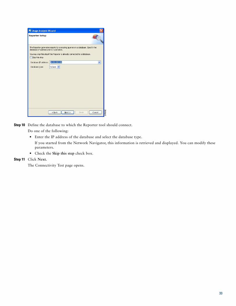
Step 10 Define the database to which the Reporter tool should connect.
Do one of the following:
• Enter the IP address of the database and select the database type.
If you started from the Network Navigator, this information is retrieved and displayed. You can modify these parameters.
• Check the Skip this step check box.
Step 11 Click Next.
The Connectivity Test page opens.
33

The wizard tests to see that the connections to the defined devices can be made.
Note If a connection to one or more of the devices cannot be made or if there is some problem with the connection (such as invalid version of the device) an error is displayed next to the device. You can skip these tests by clicking Skip connectivity test. The connections will be validated when you click Finish at the end of the wizard.
Step 12 Click Next.
The Anonymous Subscribers page opens.
34

Step 13 To disable anonymous subscriber mode, clear the Enable Anonymous Subscribers mode check box.
Step 14 Click Next.
The Confirmation page opens.
35

The actions that the wizard is about to take are listed in the page.
Step 15 Click Finish.
The Configuration Output opens.
New devices are added to the default site of the Site Manager tree in the Network Navigator.
The wizard attempts to connect to all devices that you defined. The operation fails if:
– The wizard cannot connect to any of the SCE devices that you listed in Step 4.
– You defined a CM in Step 8, but the wizard cannot connect to it.
– You defined a database in Step 10, but the wizard cannot connect to it.
If you defined a CM in Step 8, the SCE devices are configured so that the only category 1 RDR destination is the CM.
A new service configuration named Usage Analysis is created, and opens in the Service Configuration Editor.
36

The service configuration has the following characteristics:
• Report Only mode.
• The maximum Transaction RDR rate is set as the default value (250) divided by the number of SCE devices. (To configure the Transaction RDR see How to Manage Transaction RDRs. in the Cisco Service Control Application for Broadband User Guide. The content and structure of the Transaction RDR is listed in "Transaction RDR" in the “Raw Data Records: Formats and Field Contents” chapter of the Cisco Service Control Application for Broadband Reference Guide.)
The service configuration is applied to the SCE devices.
If you defined a database in Step 10:
a. The SCA BB Reporter tool is connected to the selected database.
b. The first SCE platform entered in Step 4 is selected as the source of service configuration data.
c. The Next button is enabled.
Step 16 If you did not define a database in Step 10, click Close.
The Usage Analysis wizard closes.
37

Step 17 Click Next.
The Create common reports page opens.
Step 18 To create reports, check the Create and display common reports check box.
Note Report instances will be created for four predefined report types:
• Global Bandwidth per Service
• Global Active Subscribers per Service
• Top P2P Protocols
• Global Hourly Call Minutes per Service (VoIP)
Step 19 Click Close.
The wizard closes.
The Reporter tool opens in the Console.
Report instances of each of the four report types open in the Report View of the Reporter tool.
Configuring the Subscriber Manager After installing the SM, you can configure the SM to your specific needs. In particular, you should address the following parameters at this point:
• topology—Cluster or standalone
• introduction_mode—Pull or push
• support_ip_ranges—Whether IP-ranges should be used in the installed setup
38

To configure the SM, edit the p3sm.cfg configuration file using any standard text editor. The configuration file is described in detail in the Configuration and Management module and in the Configuration File Options module. After you finish editing the p3sm.cfg configuration file, use the p3sm utility to update the SM with the new settings:
Step 1 From your workstation shell prompt, run the p3sm command.
The following p3sm command loads the configuration file and updates the SM configuration accordingly.
>p3sm --load-config
5 Cisco SCE 2000 Platform InstallationThis chapter summarizes the topologies and installation of the Cisco SCE 2000 platform. In general these are similar to the topologies and installation of the Cisco SCE8000 platform, but there are some differences.
Cisco SCE 2000 Platform TopologiesThe Cisco SCE 2000 can be deployed in the same topologies as the Cisco SCE8000 platform. The following figures illustrate the Cisco SCE 2000 topologies.
Figure 10 Single SCE Platform Single Link: In-line Topology
LINK RX
Cisco SCE 2000 Series4xGBE
TX
RX MM TX
LINK RX TX
RX MM TX
LINK RX TX
RX MM TX
LINK RX TX
RX MM TX
GBE-1
SUB LINE NET
PWR B STATUSPWR A BYPASS
GBE-2
SUB LINE/CASCADE NET
RouterRouterSubscriber 9279
8
Network
Port 2network
Port 1subscriber
39

Figure 11 Single SCE Platform Dual Link Inline Topology
Figure 12 Single SCE Platform Single Link: Receive-Only Topology
LINK RX
Cisco SCE 2000 Series4xGBE
TX
RX MM TX
LINK RX TX
RX MM TX
LINK RX TX
RX MM TX
LINK RX TX
RX MM TX
GBE-1
SUB LINE NET
PWR B STATUSPWR A BYPASS
GBE-2
SUB LINE/CASCADE NET
RouterRouterSubscriber 9279
9
Network
RouterLink 1
Link 2
RouterSubscriber
Network
LINK RX
Cisco SCE 2000 Series4xGBE
TX
RX MM TX
LINK RX TX
RX MM TX
LINK RX TX
RX MM TX
LINK RX TX
RX MM TX
GBE-1
SUB LINE NET
PWR B STATUSPWR A BYPASS
GBE-2
SUB LINE/CASCADE NET
RouterOpticalsplitter
RouterSubscriber 9279
6
Network
40

Figure 13 SCE Platform Dual Link Receive-Only Topology
LINK RX
Cisco SCE 2000 Series4xGBE
TX
RX MM TX
LINK RX TX
RX MM TX
LINK RX TX
RX MM TX
LINK RX TX
RX MM TX
GBE-1
SUB LINE NET
PWR B STATUSPWR A BYPASS
GBE-2
SUB LINE/CASCADE NET
RouterOpticalsplitter
RouterSubscriber 9279
7
Network
RouterOpticalsplitter
Link 1
Link 2
RouterSubscriber
Network
41

Figure 14 Two SCE Platforms: Dual Link Inline Topology
Installing a Cisco SCE 2000 PlatformTo install the SCE platform, complete the following steps. (For more information, refer to the Cisco SCE2000 4xGBE Installation and Configuration Guide.)
Step 1 Install the SCE platform in the rack.
Step 2 Connect the chassis ground and the power.
Step 3 Connect the CON port to a local terminal and perform the initial configuration using the setup wizard.
a. Press Enter several times until the Cisco logo appears on the local terminal and the setup configuration dialog is entered.
--- System Configuration Dialog ---At any point you may enter a question mark ‘?’ followed by ‘Enter’ for help.Use ctrl-C to abort configuration dialog at any prompt.Use ctrl-Z to jump to the end of the configuration dialog at any prompt.Default settings are in square brackets ‘[]’.Would you like to continue with the System Configuration Dialog? [yes/no]: y
LINK RX
Cisco SCE 2000 Series4xGBE
TX
RX MM TX
LINK RX TX
RX MM TX
LINK RX TX
RX MM TX
LINK RX TX
RX MM TX
GBE-1
SUB LINE NET
PWR B STATUSPWR A BYPASS
GBE-2
SUB LINE/CASCADE NET
LINK RX
Cisco SCE 2000 Series4xGBE
TX
RX MM TX
LINK RX TX
RX MM TX
LINK RX TX
RX MM TX
LINK RX TX
RX MM TX
GBE-1
SUB LINE NET
PWR B STATUSPWR A BYPASS
GBE-2
SUB LINE/CASCADE NET
RouterLink 1
RouterSubscriber
Network
Link 2RouterRouterSubscriber
Network92
800
42

b. Type y and press Enter.
The system configuration dialog begins. See Initial System Configuration, page 43 for information regarding the setup wizard.
Step 4 Connect the MNG port to the local LAN.
If using both MNG ports for redundancy, connect them to the LAN via a switch
Step 5 Cable the line ports. (See SCE 2000 Connectivity, page 45 for a summary of proper cabling for various topologies)
Initial System Configuration
Upon initial connection to the local terminal, as described above, the system configuration wizard automatically runs to guide the user through the entire setup process. The wizard prompts for all necessary parameters, displaying default values, where applicable. You may accept the default values or define other values.
With the exception of the time settings, which take effect immediately when entered, the new configuration is applied and saved only at the end of the dialog when approved by the user. Therefore, if the setup dialog is aborted, no change takes place in the configuration, other than time settings (if entered).
When the dialog is complete, you may review the new configuration before applying it. The system displays the configuration, including parameters that were not changed. The system also displays any errors that are detected in the configuration. When the configuration is satisfactory, you may apply and save the new configuration.
The following table lists all the parameters included in the initial configuration. It is recommended that you obtain values for any parameters that you will configure at this time before beginning the setup.
Note For further information regarding any configuration step or specific parameter, refer to the relevant section in the Cisco SCE 2000 and SCE 1000 Software Configuration Guide.
43

Setup Command Parameters
Table 8 Setup Command Parameters
Parameter Definition
IP address IP address of the SCE 2000.
subnet mask Subnet mask of the SCE 2000.
default gateway Default gateway.
Hostname Character string used to identify the SCE 2000. Maximum 20 characters.
admin password Admin level password. Character string from 4-100 characters beginning with an alpha character.
root password Root level password. Character string from 4-100 characters beginning with an alpha character.
password encryption status Enable or disable password encryption?
Time Settings
time zone name and offset Standard time zone abbreviation and minutes offset from UTC.
local time and date Current local time and date. Use the format: 00:00:00 1 January 2002
SNTP Configuration
broadcast client status Set the status of the SNTP broadcast client. If enabled, the SCE will synchronize its local time with updates received from SNTP broadcast servers.
unicast query interval Interval in seconds between unicast requests for update (64 – 1024)
unicast server IP address IP address of the SNTP unicast server.
DNS Configuration
DNS lookup status Enable or disable IP DNS-based hostname translation.
default domain name Default domain name to be used for completing unqualified host names
IP address IP address of domain name server. (maximum of 3 servers)
RDR Formatter Destination Configuration
IP address IP address of the RDR-formatter destination
TCP port number TCP port number of the RDR-formatter destination
Access Control Lists
Access Control List number How many ACLs will be necessary? What IP addresses will be permitted/denied access for each management interface? You may want ACLs for the following:
• Any IP access
• Telnet access
• SNMP GET access
• SNMP SET access
list entries (maximum 20 per list)
IP address, and whether permitted or denied access.
IP access ACL ID number of the ACL controlling IP access.
telnet ACL ID number of the ACL controlling telnet access.
SNMP Configuration
SNMP agent status Enable or disable SNMP management.
GET community names Community strings to allow GET access and associated ACLs (maximum 20).
SET community names Community strings to allow SET access and associated ACLs (maximum 20).
44

SCE 2000 ConnectivityThe following tables summarize SCE 2000 connectivity for the basic topologies.
Receive-only topologies use only Receive fibers.
Note Receive-only topologies can be implemented using either an optical splitter or a switch. If a switch is used, it must support SPAN functionality that includes separation between ingress and egress traffic and multiple SPAN-ports destinations.
Table 9 Single link inline connectivity
Table 10 Dual link inline connectivity
trap managers (maximum 20)
Trap manager IP address, community string, and SNMP version.
Authentication Failure trap status
Sets the status of the Authentication Failure traps.
enterprise traps status Sets the status of the enterprise traps.
system administrator Name of the system administrator.
Topology Configuration
Connection mode Is the SCE 2000 installed using inline topology or receive-only topology using an optical splitter?
type of deployment Is this a cascade topology, with two SCE 2000s connected via the cascade ports? Or is this a single platform topology?
physically connected link (cascade topology only)
In a cascade deployment this parameter sets the index for the link that this SCE 2000 is deployed on. The options for SCE 2000 are link-0 or link-1.
In a single- SCE 2000 platform deployment, this parameter is not relevant since one SCE 2000 is deployed on both links. In this case the link connected to port1-port2 is by default link-0 and the link connected to port3-port4 is be default link-1.
priority (cascade topology only)
If this is a cascaded topology, is this SCE 2000 the primary or secondary SCE 2000?
on-failure behavior (inline connection mode only)
If this SCE 2000 is deployed inline, should the failure behavior be bypass or cutoff of the link?
Admin status of the SCE 2000 after abnormal boot
After a reboot due to a failure, should the SCE 2000 remain in a Failure status or move to operational status provided no other problem was detected?
GBE Port Link Side
0/1 Link 0 Subscribers
0/2 Link 0 Network
GBE Port Link Side
0/1 Link 0 Subscribers
0/2 Link 0 Network
0/3 Link 10 Subscribers
0/4 Link 1 Network
Table 8 Setup Command Parameters
Parameter Definition
45

Table 11 Cascade connectivity
Table 12 External Optical Bypass Module connectivity: Single link
Table 13 External Optical Bypass Module connectivity: Dual link
This port on SCE 2000 #1 Connects to this...
0/1 Subscriber side network element
0/2 Network side network element
0/3 (cascade port) port 0/4 on SCE 2000 #2
0/4 (cascade port) port 0/3 on SCE 2000 #2
This port on SCE 2000 #2 Connects to this....
0/1 Subscriber side network element
0/2 Network side network element
0/3 (cascade port) port 0/4 on SCE 2000 #1
0/4 (cascade port) port 0/3 on SCE 2000 #1
This optical bypass component Connects to this...
Sub port Subscriber side network element
Net port Network side network element
Sub fiber of the pigtail fiber Sub port of the GBE-1 Line ports on the SCE 2000
Net fiber of the pigtail fiber Net port of the GBE-1 Line ports on the SCE 2000
Control port Bypass 1 9-pin D-Type connector on the rear panel of the SCE 2000 platform
External Optical Bypass Module #1
This optical bypass component Connects to this...
Sub port Subscriber side network element
Net port Network side network element
Sub fiber of the pigtail fiber Sub port of the GBE-1 Line ports on the SCE 2000
Net fiber of the pigtail fiber Net port of the GBE-1 Line ports on the SCE 2000
Control port Bypass 1 9-pin D-Type connector on the rear panel of the SCE 2000 platform
External Optical Bypass Module #2
This optical bypass component Connects to this...
Sub port Subscriber side network element
Net port Network side network element
Sub fiber of the pigtail fiber Sub port of the GBE-2 Line/Cascade ports on the SCE 2000
Net fiber of the pigtail fiber Net port of the GBE-2 Line/ Cascade ports on the SCE 2000
Control port Bypass 2 9-pin D-Type connector on the rear panel of the SCE 2000 platform
46

Multi-Gigabit Service Control Platforms (MGSCP) Topologies
In an MGSCP deployment, the exact cabling scheme depends on the number and arrangement of ports in the EtherChannel in the Cisco 7600 Series router. It is therefore not possible to give exact cabling schemes. Refer to the following general guidelines when designing the cabling scheme.
General guidelines for MGSCP topologies:• Since there are two links per Cisco SCE 2000 platform, the minimum number of platforms required is half the number of
links used.
• Each link corresponds to one port on the EtherChannel (EC) on the Cisco 7600 Series router. Each EC supports a maximum of eight ports. Therefore, if all eight EC ports are configured, four Cisco SCE 2000 platforms are required.
• For N+1 redundancy, two ports (connected to the standby platform) must be configured as standby ports on both ECs.
• Therefore, for N+1 redundancy, one router and five Cisco SCE 2000 platforms would be used to support eight links.
• If two Cisco 7600 Series routers are used (for network redundancy), one link on each Cisco SCE 2000 platform is connected to each router. This requires twice the number of Cisco SCE 2000 platforms, one platform for each link.
– A minimum of eight Cisco SCE 2000 platforms are required to support eight ports.
– For N+1 redundancy, nine Cisco SCE 2000 platforms would be used to support eight active links.
When cabling to the EC, follow these guidelines:
• The Cisco SCE platform ports MUST be connected to the EC ports in the same order on both sides.
• The EC ports should be sorted in an ascending order by their physical interface numbers.
• In a topology with two Cisco 7600 Series routers, the order of connection to the EC ports must be the same on both routers. In order for both routers to send the traffic of a given subscriber to the same SCE platform, the SCE platforms must be connected to both routers in exactly the same order (one SCE platform connected to the first link on both routers, another SCE platform connected to the second link on both routers, and so on).
6 System Requirements and Prerequisites
Overall System Requirements• The SCE platform: Local console or management workstation connected to LAN.
• SCA BB: Workstation running Windows 2000 or Windows XP
• SM: either of the following:
– Solaris-Sun SPARC machine (64-bit) running 64-bit versions of Solaris 9 or Solaris 10 with a 64-bit version of the Java Virtual Machine.
– Linux-Intel based machine with a 32-bit or 64-bit CPU running a 32-bit version of Linux with a 32-bit version of the Java Virtual Machine.
The actual number of computers required depends on the number of subscribers in the system.
• CM: either of the following:
– Solaris: Sun SPARC machine running Solaris 8 or Solaris 9.
– Linux Red Hat: IA32 machine running Red Hat Enterprise Linux 3.0 or Red Hat Enterprise Linux 4.0.
The actual number of computers required depends on the amount of traffic in the system.
• Reporter: Workstation running Windows 2000 or Windows XP
SCA BB System Requirements• Hardware Requirements, page 48
• Operating System Requirements, page 48
47

• Java Runtime Environment, page 48
Hardware Requirements • At least 1024 MB RAM is required to run the Console
• The minimal supported screen resolution for the Console is 1024x768 pixels.
Operating System Requirements
• Windows 2000 or Windows XP.
Java Runtime Environment
If you are using the optional SCA BB Service Configuration Utility, servconf, it requires access to JRE version 1.6.
You can download a JRE from the Sun™ website at http://java.com/en/download/.
To verify that the JRE is installed, run java -version from the command prompt. The Java version should start with 1.6.
If a different version of JRE is also installed on the workstation, you may need to tell servconf where to find the appropriate JRE. Do this by setting the JAVA_HOME environment variable to point to the JRE 1.6 installation directory. For example:
JAVA_HOME=C:\Program Files\Java\j2re1.6_08
SM System Requirements You can install the SM on the following platforms:
• Solaris—Sun SPARC machine (64-bit) running 64-bit versions of Solaris 9 or Solaris 10 with a 64-bit version of the Java Virtual Machine. See Table 13 Table 15.
• Linux—Intel based machine with a 32-bit or 64-bit CPU running a 32-bit version of Linux with a 32-bit version of the Java Virtual Machine. See Table 13Table 16.
The machine should conform to the system requirements listed in the following tables.
Note The specifications listed in Table 13 are minimal. They should be verified in order to guarantee specific performance and capacity requirements.
For the hardware and software system requirements for the Veritas Cluster Server, see the Cisco Service Control Management Suite Subscriber Manager User Guide, the Veritas Cluster Server chapter.
Table 14 Minimal System Hardware Requirements
Item Requirement
CPU • SUN SPARC, 64-bit, minimum 500 MHz (for Solaris)
• Intel processor, 32- or 64-bit, minimum 1 GHz (for Linux Red Hat)
RAM Minimum 1 GB
Free Disk Space Minimum 3 GB total, of which:
• Minimum 1 GB free on partition where VARDIR (SM database repository) is installed
• Minimum 0.5 GB free on partition where PCUBEDIR (SM files) is installed
• Minimum 200 MB free on partition where /tmp is mounted
Network Interface Depends on whether or not the configuration includes a cluster:
• Without cluster—One (1) 100BASE-T Ethernet
• With cluster—Six (6) 100BASE-T Ethernet
CD-ROM drive Recommended
48

Note It is strongly recommended to apply the latest patches from SUN. You can download the latest patches from the SUN patches website.
Note It is strongly recommended to apply the latest patches from Red Hat.
Note Only 32-bit versions of Linux are supported, but it is possible to install 32-bit Linux on a 64-bit CPU.
Table 15 Solaris System Software Requirements
Item Requirement
OS Solaris 5.9 64-bit or later; currently, only 64-bit versions of Solaris 5.9 and 5.10 are supported.
Solaris Core Installation
System Packages Mandatory:
• SUNWbash—GNU Bourne-Again shell (bash)
• SUNWgzip—GNU Zip (gzip) compression utility
• SUNWzip—Info-Zip (zip) compression utility
• SUNWlibC—Sun Workshop Compilers Bundled libC
• SUNWlibCx—Sun WorkShop Bundled 64-bit libC
• sudo (superuser do) package
Optional:
• SUNWadmap—system administration applications
• SUNWadmc—system administration core libraries
Table 16 Red Hat System Software Requirements
Item Requirement
OS Red Hat Enterprise Linux AS/ES 3.0/4.0; currently, only 32-bit versions are supported.
Red Hat Core Installation
System Packages Mandatory:
• GNU Bourne-Again shell (bash-2.05b-29.i386.rpm)
• GNU Data Compression Program (gzip-1.3.3-9.i386.rpm)
• File compression and packaging utility (zip-2.3-16.i386.rpm)
• Standard C++ libraries for Red Hat Linux 6.2 backward compatibility (compat-gcc-7.3-2.96.122.i386.rpm)
• sudo (superuser do) package
For integrating with the C API:
• GNU cc and gcc C compilers (gcc-3.2.3-20.i386.rpm)
• C++ support for the GNU gcc compiler (gcc-3.2.3-20.i386.rpm)
49

CM System Requirements The CM and its database are software components that run on a server platform. They can be installed on any of the following configurations:
• Sun SPARC machine (64-bit) running 64-bit versions of Solaris 9 or Solaris 10. (See Solaris Requirements, page 50)
• Intel machine (32-bit or 64-bit) running 32-bit versions of Red Hat Enterprise Linux 3.0 or Red Hat Enterprise Linux 4.0. (See Red Hat Linux Requirements, page 52)
All configurations use a 32-bit Java virtual machine (JVM).
Caution The CM must run on its own machine. You cannot run it on the same machine as the Subscriber Manager and/or other applications.
Note When using the bundled Sybase database, the server on which you install the CM can have a maximum of 4 CPU cores.
• Checking System Prerequisites, page 50
• Solaris Requirements, page 50
• Red Hat Linux Requirements, page 52
Checking System Prerequisites
The CM distribution contains a script, check_prerequisites.sh, located in the install_scripts directory. The script helps to determine if a system meets the requirements for installing a CM or the bundled Sybase database.
The script checks overall readiness of the system for a CM or Sybase installation. The main prerequisites checked are:
• CPU speed
• Amount of RAM
• Operating System version (Solaris 9 or 10, Red Hat Enterprise Linux 4 or 5)
• Additional required and optional packages
• Python installed and executable in path
• Free space for CM and Sybase homes
• Names for all network interface cards (NICs)
• Sybase kernel parameters
• Locale and time zone formats
check_prerequisites.sh [--sybhome=SYBHOME] [--cmhome=CMHOME] [--datadir=DATADIR]
Note All of the above directories must be created before running the script.
Solaris Requirements
Collection Manager Release 3.5.0 or later can be installed on any Sun SPARC Machine running Solaris that conforms to the requirements listed in the following sections.
Table 17 check_prerequisites.sh Script Options
--sybhome=SYBHOME Intended home directory for Sybase installation
--datadir=DATADIR Intended data directory for Sybase data files (for the Datadir installation method). This directory should be created on a different mount, not on the CM mount.
--cmhome=CMHOME Intended home directory for CM installation
50

• Hardware, page 51
• Software and Environment, page 51
• Setting the Locale and Time Zone, page 52
Hardware • Minimum 500 MHz CPU
• Minimum 1 GB RAM per CPU
• Hard disk:
– One hard disk, at least 18 GB
– (Recommended for bundled installations) A second hard disk (at least 18 GB), to store Sybase data
• 100BASE-T network interface
Software and Environment • Solaris Version 5.9 64-bit build 04/01 or later (currently only Solaris Version 5.9 and 5.10 are supported).
• Solaris Core Installation.
• Install the following additional packages:
• If you are installing the CM in bundled mode with the Sybase database, you must install the following package:
• (Optional) The following packages may be installed (for sysadmin applications such as sys-unconfig):
• To use the Python scripts, a Python interpreter Version 2.2.1 or later must be present on the system. You can install the following interpreter package:
• The Python package requires the installation of two additional packages:
• You can download these packages from http://sunfreeware.com/
system SUNWbash GNU Bourne-Again shell (bash)
system SUNWgzip The GNU Zip (gzip) compression utility
system SUNWzip The Info-Zip (zip) compression utility
system SUNWlibC Sun Workshop Compilers Bundled libC
system SUNWlibCx Sun WorkShop Bundled 64-bit libC
system SUNWipc Interprocess Communication
system SUNWadmap System administration applications
system SUNWadmc System administration core libraries
application SMCpythn (Solaris 9)
SMCpython (Solaris 10)
Python
application SMClibgcc libgcc
application SMCncurs ncurses
51

The root (/) partition must have at least 104 MB of free space to install these packages.
• Apply the latest recommended patches from Sun:
– For Solaris 9, go to http://sunsolve.sun.com/pub-cgi/show.pl?target=patches/xos-9&nav=pub-patches
– For Solaris 10, go to http://sunsolve.sun.com/pub-cgi/show.pl?target=patches/xos-10&nav=pub-patches
– For Java, go to http://sunsolve.sun.com/pub-cgi/show.pl?target=patches/J2SE
• If you are using Sybase, install the current Solaris patches recommended by Sybase:
• At least 8 GB free on the partition where the CM is to be installed. (This is used for CSV storage and persistent buffers.)
• (For installations with bundled Sybase) At least 3 GB free on one partition for the Sybase home directory.
• (For installations with bundled Sybase) Free space on one partition to hold the desired size of the Sybase data and logs (the sizes are configurable at install time).
• (For installations with bundled Sybase where the legacy (pre-3.0) Cisco Service Control Application Suite (SCAS) Reporter is to be used.) An FTP server should be listening on port 21 so that the SCA Reporter can authenticate against it.
• (For installations with bundled Sybase) Before installation, verify that all IP addresses that are configured for the machine NICs have hostnames associated with them in /etc/hosts or in another active naming service. (This is a limitation of Sybase Adaptive Server Enterprise.)
• (For installations with bundled Sybase) Use the set_shmmax.sh script (located under install-scripts/) to configure the kernel memory.
• Additionally, at startup you must load the IPC module by putting the following lines in the file /etc/system:
forceload: sys/shmsys
• If you are using database periodic delete, the scmscm user should be able to schedule and run cron jobs.
Setting the Locale and Time ZoneFor correct CM and Sybase operation, U.S. English locale must be used. To set the locale, put the following line in the /etc/TIMEZONE configuration file (changes to this file require a restart to take effect):
LANG=en_US
Solaris also needs to have this locale installed. Verify that the locale is installed by checking that the directory /usr/lib/locale/en_US exists. If the directory does not exist, install the locale files from the Solaris CDs.
Red Hat Linux Requirements
Collection Manager Version 3.5.0 or later can be installed on any i386 running Red Hat Linux that conforms to the requirements listed in the following sections.
• Hardware, page 52
• Software and Environment, page 52
• Setting the Locale and Time Zone, page 53
Hardware• Minimum 800 MHz CPU
• Minimum 1 GB RAM per CPU
• Hard disk:
– One hard disk, at least 18 GB
– (Recommended for bundled installations) A second hard disk (at least 18 GB), to store Sybase data
• 100BASE-T network interface
Software and Environment • Red Hat Linux 4.0.
– kernel -2.6.9-5
– glibc-2.3.4-2
– compat-libstdc++-33-3.2.3-47.3
52

• Red Hat Linux 5.0
– kernel-2.6.18-8.el5
– glibc-2.5-12
– compat-libstdc++-33-3.2-61
• Red Hat Enterprise "Base" Installation.
• (For installations with bundled Sybase) Install the following additional package: compat-libstdc++. This package is available on the Red Hat installation CD.
• Apply latest recommended patches from Red Hat.
• (For installations with bundled Sybase) Install current patches recommended by Sybase.
• Reserve at least 8 GB free on the partition where the CM is to be installed. (This is used for CSV storage and persistent buffers.)
• (For installations with bundled Sybase) At least 1 GB free on some partition for the Sybase home directory.
• (For installations with bundled Sybase where the legacy (pre-Version 3.0) Cisco Service Control Application Suite (SCAS) Reporter is to be used.) An FTP server should be listening on port 21 so that the SCA Reporter can authenticate against it.
• (For installations with bundled Sybase) Before installation, verify that all IP addresses that are configured for the machine NICs have hostnames associated with them in /etc/hosts or in another active naming service. (This is a limitation of Sybase Adaptive Server Enterprise.)
• (For installations with bundled Sybase) Use the set_shmmax.sh script (located under install-scripts/) to configure the kernel memory.
• If you are using database periodic delete, the scmscm user should be able to schedule and run cron jobs.
Setting the Locale and Time Zone
• For correct CM and Sybase operation, U.S. English locale (en_US) must be used.
7 Obtaining Documentation and Submitting a Service RequestFor information on obtaining documentation, submitting a service request, and gathering additional information, see the monthly What’s New in Cisco Product Documentation, which also lists all new and revised Cisco technical documentation, at:
http://www.cisco.com/en/US/docs/general/whatsnew/whatsnew.html
Subscribe to the What’s New in Cisco Product Documentation as a Really Simple Syndication (RSS) feed and set content to be delivered directly to your desktop using a reader application. The RSS feeds are a free service and Cisco currently supports RSS Version 2.0.
53

Americas HeadquartersCisco Systems, Inc.San Jose, CA
Asia Pacific HeadquartersCisco Systems (USA) Pte. Ltd.Singapore
Europe HeadquartersCisco Systems International BVAmsterdam, The Netherlands
Cisco has more than 200 offices worldwide. Addresses, phone numbers, and fax numbers are listed on the Cisco Website at www.cisco.com/go/offices.
OL-18872-01
Cisco and the Cisco Logo are trademarks of Cisco Systems, Inc. and/or its affiliates in the U.S. and other countries. A listing of Cisco's trademarks can be found at www.cisco.com/go/trademarks. Third party trademarks mentioned are the property of their respective owners. The use of the word partner does not imply a partnership relationship between Cisco and any other company. (1005R)
Any Internet Protocol (IP) addresses used in this document are not intended to be actual addresses. Any examples, command display output, and figures included in thedocument are shown for illustrative purposes only. Any use of actual IP addresses in illustrative content is unintentional and coincidental.
© 2011 Cisco Systems, Inc. All rights reserved.
Recommended