Circuit Switching and Packet Switching

Switched Network o Physically separate path for
each pair of communicating end systems
o Using switches we can reduce the number of paths
Point-to-point network Switched network
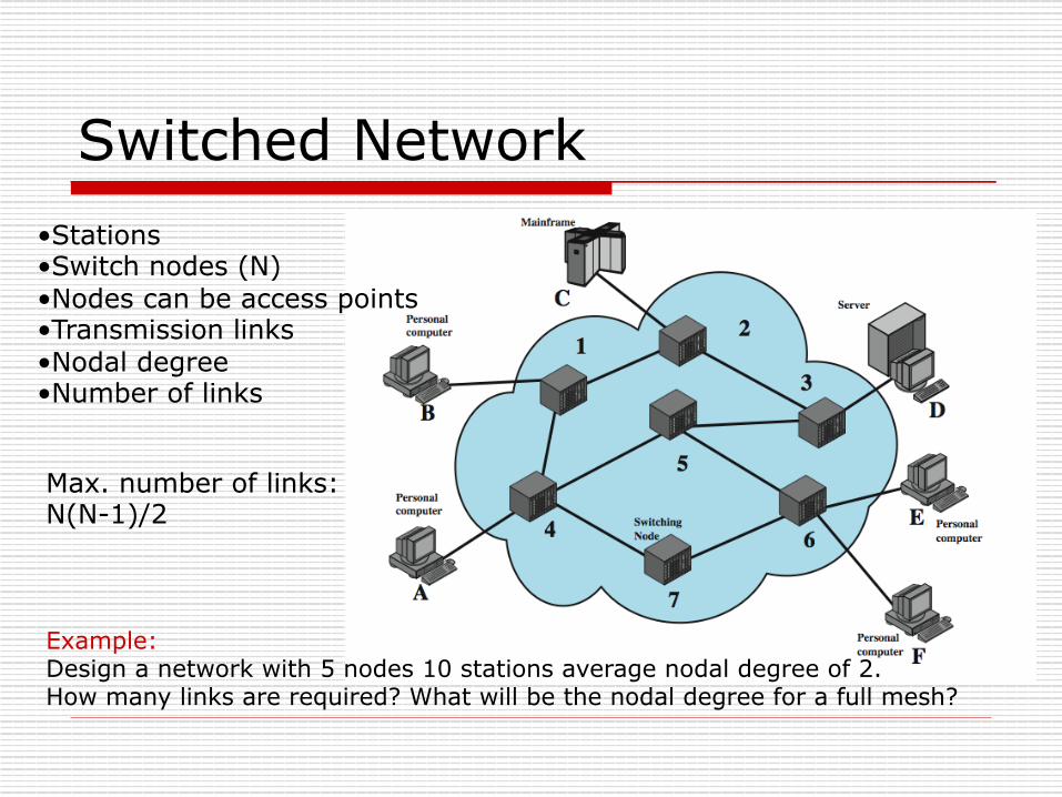
Switched Network • Stations • Switch nodes (N) • Nodes can be access points • Transmission links • Nodal degree • Number of links
Max. number of links: N(N-1)/2
Example: Design a network with 5 nodes 10 stations average nodal degree of 2. How many links are required? What will be the nodal degree for a full mesh?
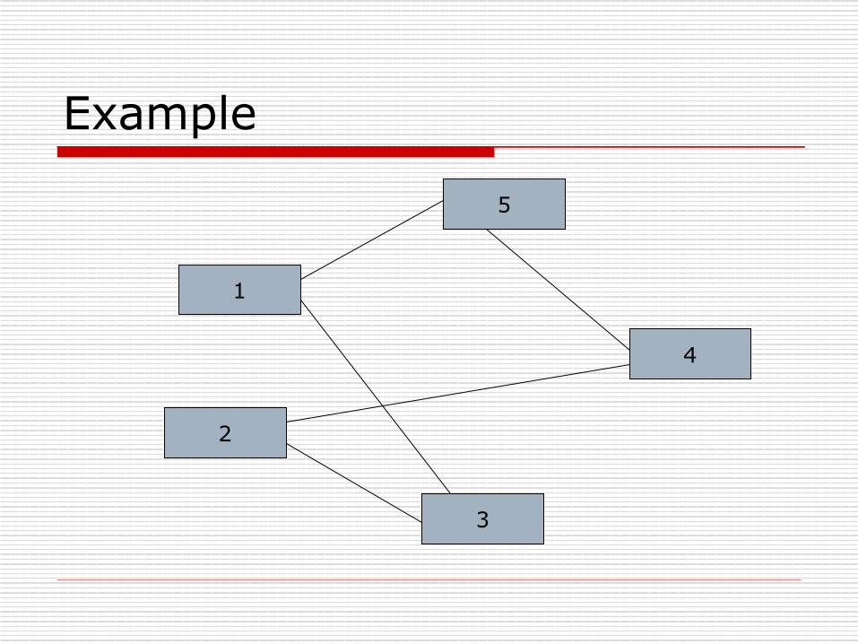
Example
1
2
5
3
4

Communications Network o a collection of nodes and links o nodes may connect to other nodes only, or
to stations and other nodes o network is usually partially connected (not
a full mesh) n some redundant connections are desirable
o switching technologies n circuit switching n packet switching

Circuit Switching o uses a dedicated path between two stations
n path is reserved for the single pair of end users o has three phases
n circuit establish n data transfer n circuit disconnect
o inefficient n channel capacity dedicated for duration of connection n if no data, capacity wasted n inefficient use of the path if there is bursty traffic
o set up (connection) takes time – setup time o once connected, transfer is transparent

Public Circuit Switched Network
Thousands of users May be connected directly to the end-office
Direct link to the subscriber
caller number: 214-403-2211
Called user number: 707-663-2211
214 707
663-xxxx
403-xxxx
Rohnert Park, CA Dallas, TX
o North American Numbering Plan (NPAN) o International Direct Distance Dialing (IDDD)
n Each country has a country code n To access the country code you need a notification code (0
or 011)
NPA – NXX - XXXX
Area Code Check out the Geographical NPAs Plan.
Exchange Code
Subscriber Line Number
22xx

Circuit Establishment
Santa Rosa
San Francisco
- Once the circuit is setup the transmission is transparent à no transmission delay and no delay variations

Circuit Switching Inefficiency o Assume set-up time is 150 msec and the data
length is 1000 bytes transmitting at 64Kbps. n Only takes 125 msec to transmit the data!
o Not efficient when data occurs in bursts separated by idle periods
Bursty data:

Event Timing o Assume R=2.5Gbps o N=4 (intermediate nodes) o Message length
L=1000Kbit o Control Message length L’
= 10 bit o Data Transmission Delay =
L/R (sec) o Control Message
Transmission Delay = L’/R (sec)

Circuit Switch Elements
o NI allows connecting to digital or analog lines
o CU sets up the switch fabric (SF)
o SF is the hardware that actually causes switching
CU
NI
SF
SF
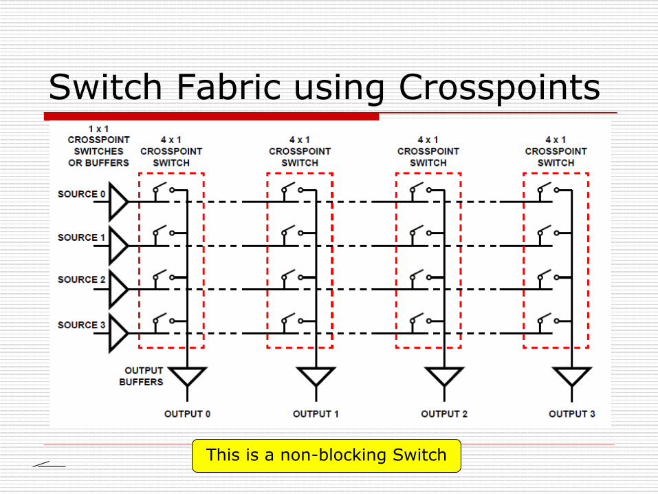
Switch Fabric using Crosspoints
This is a non-blocking Switch

Blocking or Non-blocking o non-blocking network
n permits all stations to connect at once n used for some data connections
o blocking network n may be unable to connect stations because all
paths are in use n used on voice systems
o non-blocking is cheaper n not everyone can make a call at the same time
Switching technologies: • Space Division Switching • Time Division Switching

Space Division Switch - Non-blocking
o NxN crosspoints o For 10^6 users, a crossbar would
require 10^12 crosspoints (N^2)

Multiple Stage Space Switch - n x k
n x k
n x k
n x k
k x n
k x n
k x n
k x n
N x N n n
N x N n n
N = 16 n = 4 k = 2
16x16 Rectangular Array: 256 crosspoints Three Stage Switch: 96 crosspoints
k (N/n x N/n) second stages!

Blocked Calls are possible... n x k
n x k
n x k
n x k
k x n
k x n
k x n
k x n
N x N n n
N x N n n
N = 16 n = 4 k = 2
2 lines blocked.
k (N/n x N/n) second stages!

3 Stage Space Division Switch N = 10 n = 5 k = 2
3 lines blocked.

… also called Clos Network o if k = 2n-1 or greater nonblocking switch o If k < 2n-1, blocking can occur o ….. the higher k value the more crosspoints
are required for the crossbar switch! (for each additional k we add n more crosspoints!)
o Example: suppose that 1000 users using 10 input per input module. How many second stages are required in order to have a non-blocking switch?
n x k (4x2)

Example - Solution n N=1000, n=10; n There are N/n = 1000/10
= 100 switches at the first and third stages.
n At the first stage, there are 10 x k and at the third stage
n There are k switches in the second stage
n The second stage will have k switches of size 100 x 100.
n If k = 2n-1=19, then the resulting switch will be nonblocking.
n If k < 19, then blocking can occur.
o In the case of a full 1000 x 1000 crossbar switch, no blocking occurs but 1,000,000 (a million) crosspoints are required.
o For n=10 and k=19, each switch at the first stage is a 10 x 19 crossbar which requires 190 crosspoints and there are 100 such switches.
o Same for the third stage. o So the first and third stages use
2x190x100=38,000 crosspoints altogether.
o The second stage consists of k=19 crossbars each of size 100 x 100 because N/n=1000/10 = 100.
o So the second stage uses 190,000 crosspoints.
o Altogether, the Clos construction uses 228,000 crosspoints
http://people.seas.harvard.edu/~jones/cscie129/nu_lectures/lecture11/switching/clos_network/clos_network.html
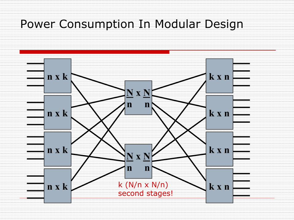
Power Consumption In Modular Design
n x k
n x k
n x k
n x k
k x n
k x n
k x n
k x n
N x N n n
N x N n n
k (N/n x N/n) second stages!

Power Consumption In Modular Design - Power Efficient Architecture
n x k
n x k
n x k
n x k
k x n
k x n
k x n
k x n
N x N n n
N x N n n
k (N/n x N/n) second stages!
O F F
O F F

Example (Remember)
n x k
n x k
n x k
n x k
k x n
k x n
k x n
k x n
N x N n n
N x N n n
k (N/n x N/n) second stages!

Time Division Switching o modern digital systems use
intelligent control of space & time division elements
o use digital time division techniques n set up and maintain virtual
circuits n partition low speed bit stream
into pieces that share higher speed stream
n individual pieces manipulated by control logic to flow from input to output

http://archvlsi.ics.forth.gr/~kateveni/534/04a/s21_ts.html
Remember: This is circuit switching which uses time slots (TDM)!

Packet Switching o circuit switching was designed for voice o packet switching was designed for data
n transmitted in small packets o packets contains user data and control info
n user data may be part of a larger message n control info includes routing (addressing) info
o packets are received, stored briefly (buffered) and past on to the next node n packets are queued

Packet Switching
Advantages o line efficiency
n single link shared by many packets over time n packets queued and transmitted as fast as
possible o data rate conversion
n stations connect to local nodes at their own speed n nodes buffer data if required to equalize rates
o packets accepted even when network is busy o priorities can be used

Data Rate Conversion
eecs122, walrand

Switching Techniques o The station breaks long message into
packets o Packets are sent one at a time to the
network o Packets can be handled in two ways
n datagram n virtual circuit
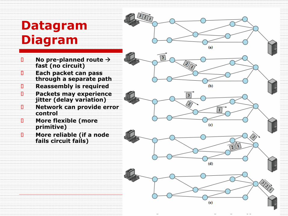
Datagram Diagram o No pre-planned route à
fast (no circuit) o Each packet can pass
through a separate path o Reassembly is required o Packets may experience
jitter (delay variation) o Network can provide error
control o More flexible (more
primitive) o More reliable (if a node
fails circuit fails)

Virtual Circuit Diagram o call setup phase is required o Fixed route (circuit
switching) o Each packet has VC ID o No routing decisions at the
intermediate nodes --> fast delivery

Event Timing (With ACK)

Event Timing Due to packet queue!
No call setup
Each packet is routed in
dependently à higher jitter and possibly
delay per node

Packet Size and Delay K =Message_ length(bit)P = Packet _ length(bit)R = Line_ transmission_ rate(bps)N = # switch_nodes_ in_ the_ pathDcircuit _ switch = K / R
Dpacket _ switch =PR(N +1)+ K !P
R
Dmessage_ switch =KR(N +1)
The transmission delay for the first packet
N=2 Two Hops!
X a b Y
Note: we are ignoring the overhead and setup delay and propagation delay
If the whole message is broken into multiple smaller packets. In each case the entire message/packet must be received before retransmission!
e.g., entire message

Example: o Assume the message
is 10^6 bits long o Transmission rate is
50Kbps o Four switches in the
path o Packet size is 2000bit o Calculate the delay for
packet switched network and circuit switched network
o Neglect call setup and overhead
sec16.2050000/)20001000000(50000/)5(2000
)1()1(
sec2050000/1000000/
45000020001000000
_
_
=−+=
+=−
++=
==
=
=
=
=
=
KPN
RK
RPKN
RPD
RKDN
bpsRbitPbitK
switchpacket
switchcircuit
Note if P<<K then delay will be the same!
http://www.slideshare.net/Convergent_Technology/next-generation-networks-8193677
Applet:

Example: o Assume the message
is 10^6 bits long o Transmission rate is
50Kbps o Four switches in the
path o Packet size is 2000bit o Calculate the delay for
packet switched network and circuit switched network
o Neglect call setup and overhead
sec16.2050000/)20001000000(50000/)5(2000
)1()1(
sec2050000/1000000/
45000020001000000
_
_
=−+=
+=−
++=
==
=
=
=
=
=
KPN
RK
RPKN
RPD
RKDN
bpsRbitPbitK
switchpacket
switchcircuit
The Throughput =
Total number of bits transmitted ---------------------------------------------
Total Delay
http://www.slideshare.net/Convergent_Technology/next-generation-networks-8193677
Applet:
Goodput =
Total number of useful bits transmitted ---------------------------------------------
Total Delay

Circuit vs. Packet Switching o performance depends on various
delays n propagation delay n transmission time n node delay n transparency n amount of overhead
X.25 o ITU-T standard for interface between
host and packet switched network o almost universal on packet switched
networks and packet switching in ISDN
o defines three layers n Physical n Link n Packet

X.25 - Physical o interface between station node link o two ends are distinct
n Data Terminal Equipment DTE (user equipment)
n Data Circuit-terminating Equipment DCE (node)
o physical layer specification is X.21 o can substitute alternative such as
EIA-232

X.25 - Link o Link Access Protocol Balanced (LAPB)
n Subset of HDLC (described later) o Provides reliable transfer of data over
link o Sends a sequence of frames

X.25 - Packet o provides a logical connections (virtual
circuit) between subscribers o all data in this connection form a
single stream between the end stations
o established on demand o termed external virtual circuits

X.25 Use of Virtual Circuits

User Data and X.25 Protocol Control Information
Link Access Protocol Balanced

Issues with X.25 o key features include:
n call control packets, in-band signaling n multiplexing of virtual circuits at layer 3 n layers 2 and 3 include flow and error
control, hence, have considerable overhead o no hop by hop error or flow control (rather than
end-to-end) – hop-by-hop ACK
o not appropriate for modern fast digital systems requiring high reliability

Frame Relay o designed to eliminate most X.25 overhead o has large installed base o key differences:
n call control carried in separate logical connection n multiplexing and switching at layer 2 n no hop by hop error or flow control n Hence, end to end flow and error control (if used)
are done by higher layer
o a single user data frame is sent from source to destination and higher layer ACK sent back

Advantages and Disadvantages o lost link by link error and flow control o increased reliability means less an
issue o streamlined communications process
n lower delay n higher throughput
o frame relay can be used for access speeds up to and over 2Mbps

Protocol Architecture

LAPF Functionality
o LAPF (Link Access Procedure for Frame Mode Bearer Services) defined in Q.922
o only core functionality used: n frame delimiting, alignment and transparency n frame mux and demux using addressing field n ensure frame is integral number of octets n ensure frame is neither too long nor short n detection of transmission errors n congestion control functions
o form sub-layer of data link layer n data transfer between subscribers only

Frame Relay Data Link Connections o logical connection between
subscribers o data transferred over them o not protected by flow or error control o uses separate connection for call
control o overall results in significantly less
work in network
User Data Transfer o only have one frame type which
n carries user data o no control frames means
n no inband signaling n no sequence numbers
o flag and FCS function as in HDLC o address field carries DLCI o DLCI (Data Link Connection Identifier)
has local significance only

Summary o circuit verses packet switching
network approaches o X.25 o frame relay

References o http://people.seas.harvard.edu/~jones/
cscie129/nu_lectures/lecture11/switching/clos_network/clos_network.html
o Switch design http://www2.cs.uh.edu/~johnsson/cosc6365_08/Lecture09_S.pdf
o Circuit-Switched Coherence www.eecg.toronto.edu/~enright/circuit-switched-coherence.ppt
Recommended