Usi
ng U
ML
, Pat
tern
s, a
nd J
ava
Ob
ject
-Ori
ente
d S
oftw
are
En
gin
eeri
ng
Chapter 6 System Design:
Decomposing the System
Bernd Bruegge & Allen H. Dutoit Object-Oriented Software Engineering: Using UML, Patterns, and Java 2
Design
“There are two ways of constructing a software design: One way is to make it so simple that there are obviously no deficiencies, and the other way is to make it so complicated that there are no obvious deficiencies.”
- C.A.R. Hoare
Bernd Bruegge & Allen H. Dutoit Object-Oriented Software Engineering: Using UML, Patterns, and Java 3
Why is Design so Difficult?
♦ Analysis: Focuses on the application domain
♦ Design: Focuses on the solution domainDesign knowledge is a moving target
The reasons for design decisions are changing very rapidly Halftime knowledge in software engineering: About 3-5 years
What I teach today will be out of date in 3 years
Cost of hardware rapidly sinking
♦ “Design window”: Time in which design decisions have to be made
♦ TechniqueTime-boxed prototyping
Bernd Bruegge & Allen H. Dutoit Object-Oriented Software Engineering: Using UML, Patterns, and Java 4
The Purpose of System Design
♦ Bridging the gap between desired and existing system in a manageable way
♦ Use Divide and ConquerWe model the new system to be developed as a set of subsystems
Problem
Existing System
NewSystem
Bernd Bruegge & Allen H. Dutoit Object-Oriented Software Engineering: Using UML, Patterns, and Java 5
System Design
♦ Transforms an analysis model into a system design model.
♦ During this phase,
- Developers define the design goals of the project and decompose the system into smaller systems.
- Developers select strategiesstrategies for building the system.
♦ The result of system design is a model that includes a subsystem decomposition and a clear description of each of these strategies.
Bernd Bruegge & Allen H. Dutoit Object-Oriented Software Engineering: Using UML, Patterns, and Java 6
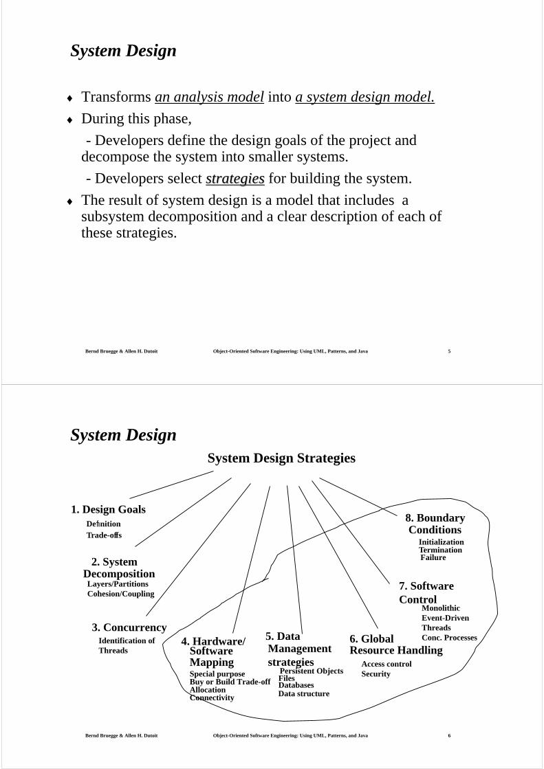
System DesignSystem Design Strategies
2. System
Layers/PartitionsCohesion/Coupling
5. Data
1. Design GoalsDefinitionTrade-offs
4. Hardware/
Special purpose
Software
Buy or Build Trade-offAllocationConnectivity
3. Concurrency
Data structure
Persistent ObjectsFilesDatabases
Managementstrategies Access control
Security
6. Global Resource Handling
8. BoundaryConditions
InitializationTerminationFailure
Decomposition
Mapping
7. Software Control
Identification of Threads
MonolithicEvent-DrivenThreadsConc. Processes
Bernd Bruegge & Allen H. Dutoit Object-Oriented Software Engineering: Using UML, Patterns, and Java 7
Overview
System Design I (Today)0. Overview of System Design
1. Design Goals
2. Subsystem Decomposition
System Design II: Addressing Design Goals (next lecture)3. Concurrency
4. Hardware/Software Mapping
5. Persistent Data Management
6. Global Resource Handling and Access Control
7. Software Control
8. Boundary Conditions
Bernd Bruegge & Allen H. Dutoit Object-Oriented Software Engineering: Using UML, Patterns, and Java 8
System Design
♦ Be decomposed into several activities as follows:
1) Identify design goals
Developers identify and priorities the qualities of the system
that they should optimize.
2) Design the initial subsystem decomposition
Developers decompose the system into smaller parts
based on use case and analysis models.
3) Refine the subsystem decomposition to address the design
goals [ch 7]
Bernd Bruegge & Allen H. Dutoit Object-Oriented Software Engineering: Using UML, Patterns, and Java 9
How to use the results from the Requirements Analysis for System Design
♦ Nonfunctional requirements =>Activity 1: Design Goals Definition
♦ Functional model =>Activity 2: System decomposition
(Selection of subsystems based on functional requirements, cohesion, and coupling)
♦ Object model => Activity 4: Hardware/software mappingActivity 5: Persistent data management
♦ Dynamic model =>Activity 3: ConcurrencyActivity 6: Global resource handlingActivity 7: Software control
♦ Subsystem DecompositionActivity 8: Boundary conditions
Bernd Bruegge & Allen H. Dutoit Object-Oriented Software Engineering: Using UML, Patterns, and Java 10
How do we get the Design Goals?
Let’s look at a small example
Current Situation:
Computers must be used in the office
What we want:
A computer that can be used in mobile situations.
Bernd Bruegge & Allen H. Dutoit Object-Oriented Software Engineering: Using UML, Patterns, and Java 11
QuickTime?and a decompressor
are needed to see this picture.
Example: Current Desktop Development
Bernd Bruegge & Allen H. Dutoit Object-Oriented Software Engineering: Using UML, Patterns, and Java 12
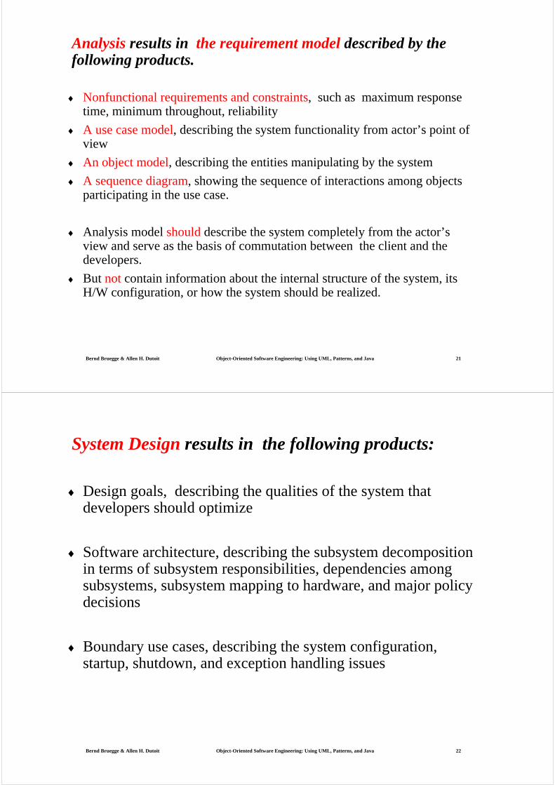
Single OutputDevice
Precise Input
Direction where the user looks is
irrelevant
Fixed NetworkConnection
Location ofuser does not
matter
Identify Current Technology Constraints

Bernd Bruegge & Allen H. Dutoit Object-Oriented Software Engineering: Using UML, Patterns, and Java 13
Single OutputDevice
Precise Input
Direction where the user looks is
irrelevant
Fixed NetworkConnection
Location ofuser does not
matter
Multiple OutputDevices
Vague Input
Direction where the user looks is
relevant
Dynamic NetworkConnection
Location-based
Generalize Constraints using Technology Enablers
Bernd Bruegge & Allen H. Dutoit Object-Oriented Software Engineering: Using UML, Patterns, and Java 14
Establish New Design Goals
Mobile Network Connection
Multiple Output Devices
Location-Based
Multimodal Input (Users Gaze, Users Location, …)
Vague input

Bernd Bruegge & Allen H. Dutoit Object-Oriented Software Engineering: Using UML, Patterns, and Java 15
Sharpen the Design Goals
Location-based input
Input depends on user location
Input depends on the direction where the user looks (“ego-centric systems”)
Multi-modal input
The input comes from more than one input device
Dynamic connection
Is there a possibility of further generalizations?
Example: location can be seen as a special case of context
User preference is part of the context
Interpretation of commands depends on context
Bernd Bruegge & Allen H. Dutoit Object-Oriented Software Engineering: Using UML, Patterns, and Java 16
Prototype the Desired System
QuickTime?and aVideo decompressor
are needed to see this picture.

Bernd Bruegge & Allen H. Dutoit Object-Oriented Software Engineering: Using UML, Patterns, and Java 17
List of Design Goals
♦ Reliability♦ Modifiability♦ Maintainability♦ Understandability♦ Adaptability♦ Reusability♦ Efficiency♦ Portability♦ Traceability of requirements♦ Fault tolerance♦ Backward-compatibility♦ Cost-effectiveness♦ Robustness♦ High-performance
Good documentation
Well-defined interfaces
User-friendliness
Reuse of components
Rapid development
Minimum # of errors
Readability
Ease of learning
Ease of remembering
Ease of use
Increased productivity
Low-cost
Flexibility
Bernd Bruegge & Allen H. Dutoit Object-Oriented Software Engineering: Using UML, Patterns, and Java 18
Coupling & Cohesion
♦ A fundamental goal of software design is to structure the software product so that the number and complexity of interconnections between components is minimized.
♦ For achieving this goal, that is, involves the concept of coupling &cohesion.
♦ First described by Stevens, Constantine, and Myers (STE74)

Bernd Bruegge & Allen H. Dutoit Object-Oriented Software Engineering: Using UML, Patterns, and Java 19
Relationship Between Design Goals
Reliability
Low cost Increased ProductivityBackward-CompatibilityTraceability of requirementsRapid developmentFlexibility
Client
End User
(Customer,Portability
Good Documentation
RuntimeEfficiency
Sponsor)
Developer/Maintainer
Minimum # of errorsModifiability, ReadabilityReusability, AdaptabilityWell-defined interfaces
FunctionalityUser-friendlinessEase of UseEase of learningFault tolerantRobustness
NielsonUsability Engineering
MMK, HCIRubin
Task Analysis
Bernd Bruegge & Allen H. Dutoit Object-Oriented Software Engineering: Using UML, Patterns, and Java 20
Typical Design Trade-offs
♦ Functionality vs. Usability
♦ Cost vs. Robustness
♦ Efficiency vs. Portability
♦ Rapid development vs. Functionality
♦ Cost vs. Reusability
♦ Backward Compatibility vs. Readability
Bernd Bruegge & Allen H. Dutoit Object-Oriented Software Engineering: Using UML, Patterns, and Java 21
Analysis results in the requirement model described by the following products.
♦ Nonfunctional requirements and constraints, such as maximum response time, minimum throughout, reliability
♦ A use case model, describing the system functionality from actor’s point of view
♦ An object model, describing the entities manipulating by the system
♦ A sequence diagram, showing the sequence of interactions among objects participating in the use case.
♦ Analysis model should describe the system completely from the actor’s view and serve as the basis of commutation between the client and the developers.
♦ But not contain information about the internal structure of the system, its H/W configuration, or how the system should be realized.
Bernd Bruegge & Allen H. Dutoit Object-Oriented Software Engineering: Using UML, Patterns, and Java 22
System Design results in the following products:
♦ Design goals, describing the qualities of the system that developers should optimize
♦ Software architecture, describing the subsystem decomposition in terms of subsystem responsibilities, dependencies among subsystems, subsystem mapping to hardware, and major policy decisions
♦ Boundary use cases, describing the system configuration, startup, shutdown, and exception handling issues
Bernd Bruegge & Allen H. Dutoit Object-Oriented Software Engineering: Using UML, Patterns, and Java 23
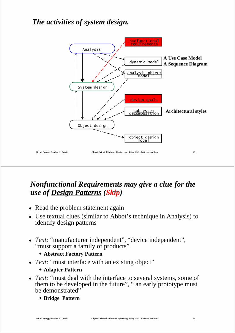
The activities of system design.
System design
Object design
object designmodel
design goals
subsystemdecomposition
Analysis
analysis objectmodel
dynamic model
nonfunctionalrequirements
A Use Case ModelA Sequence Diagram
Architectural styles
Bernd Bruegge & Allen H. Dutoit Object-Oriented Software Engineering: Using UML, Patterns, and Java 24
Nonfunctional Requirements may give a clue for the use of Design Patterns (Skip)
♦ Read the problem statement again♦ Use textual clues (similar to Abbot’s technique in Analysis) to
identify design patterns
♦ Text: “manufacturer independent”, “device independent”, “must support a family of products”
Abstract Factory Pattern
♦ Text: “must interface with an existing object”Adapter Pattern
♦ Text: “must deal with the interface to several systems, some of them to be developed in the future”, “ an early prototype must be demonstrated”
Bridge Pattern
Bernd Bruegge & Allen H. Dutoit Object-Oriented Software Engineering: Using UML, Patterns, and Java 25
Textual Clues in Nonfunctional Requirements
♦ Text: “complex structure”, “must have variable depth and width”
Composite Pattern
♦ Text: “must interface to an set of existing objects”Façade Pattern
♦ Text: “must be location transparent”Proxy Pattern
♦ Text: “must be extensible”, “must be scalable”Observer Pattern
♦ Text: “must provide a policy independent from the mechanism”Strategy Pattern
Bernd Bruegge & Allen H. Dutoit Object-Oriented Software Engineering: Using UML, Patterns, and Java 26
System Design Concepts (cont.)
♦ 6.3.1: subsystem and its relationship to classes
♦ 6.3.2: interface of subsystems
-Subsystem provide services to other systems
-A service is a set of related operations that share a common purpose.
♦ During system design, define the subsystems based on services they provide.
♦ Later, during object design, define the subsystem interfacebased on the operations it provides.
♦ May say, good subsystem decomposition should minimize coupling and maximize cohesion.
Bernd Bruegge & Allen H. Dutoit Object-Oriented Software Engineering: Using UML, Patterns, and Java 27
System design (cont.)
♦ Two properties of subsystems, coupling and cohesion:
-Coupling measures dependencies between two subsystems,
-Cohesion measures dependencies among classes within
a subsystem
♦ For relating between subsystems, layering and partitioning:
-Layering allows a system to be organized as a hierarchy of subsystems
-Partitioning organizes subsystems as peers that mutually provide different services to each other.
Bernd Bruegge & Allen H. Dutoit Object-Oriented Software Engineering: Using UML, Patterns, and Java 28
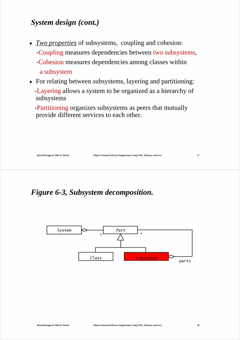
Classparts
*System Part
*
Subsystem
Figure 6-3, Subsystem decomposition.

Bernd Bruegge & Allen H. Dutoit Object-Oriented Software Engineering: Using UML, Patterns, and Java 29
Section 2. System Decomposition
♦ Subsystem (UML: Package)Collection of classes, associations, operations, events and constraintsthat are interrelatedSeed for subsystems: UML Objects and Classes.
♦ (Subsystem) Service: Group of operations provided by the subsystem Seed for services: Subsystem use cases
♦ Service is specified by Subsystem interface:Specifies interaction and information flow from/to subsystem boundaries, but not inside the subsystem. Often called API: Application programmer’s interface, but this term should used during implementation, not during System DesignSubsystem interface includes the name of operations, their types, and return values.
Bernd Bruegge & Allen H. Dutoit Object-Oriented Software Engineering: Using UML, Patterns, and Java 30
Figure 6-4, Subsystem decomposition for an accident management system.
MapMangement IncidentManagement
FieldOfficerInterface DispatcherInterface
Notification IncidentManagement

Bernd Bruegge & Allen H. Dutoit Object-Oriented Software Engineering: Using UML, Patterns, and Java 31
Services and Subsystem Interfaces
♦ Service: A set of related operations that share a common purpose
Notification subsystem service:LookupChannel()
SubscribeToChannel()
SendNotice()
UnscubscribeFromChannel()
Services are defined in System Design
♦ Subsystem Interface: Set of fully typed related operations.Subsystem Interfaces are defined in Object Design
Also called application programmer interface (API)
Bernd Bruegge & Allen H. Dutoit Object-Oriented Software Engineering: Using UML, Patterns, and Java 32
Subsystem decomposition for an accident management system.
FieldOfficerInterface DispatcherInterface
Notification subsystem service:
LookupChannel()SubscribeToChannel()SendNotice()UnscubscribeFromChannel()
Bernd Bruegge & Allen H. Dutoit Object-Oriented Software Engineering: Using UML, Patterns, and Java 33
Coupling:
♦ The strength of coupling between two components may be influenced by the complexity of interface,
the type of connection, and
the type of communication.
Coupling between components may be ranked on a scale of
strongest (least desired) to weakest (most desired) as follows:
1) Content coupling
2) Common coupling
3) Control coupling
4) Stamp coupling
5) Data coupling
Bernd Bruegge & Allen H. Dutoit Object-Oriented Software Engineering: Using UML, Patterns, and Java 34
♦ 1) Loosely coupled: their subsystems are independent,
so modifications to one of the subsystems will have little
impact on the other.
2) Strongly coupled: impact on the other subsystem
Bernd Bruegge & Allen H. Dutoit Object-Oriented Software Engineering: Using UML, Patterns, and Java 35
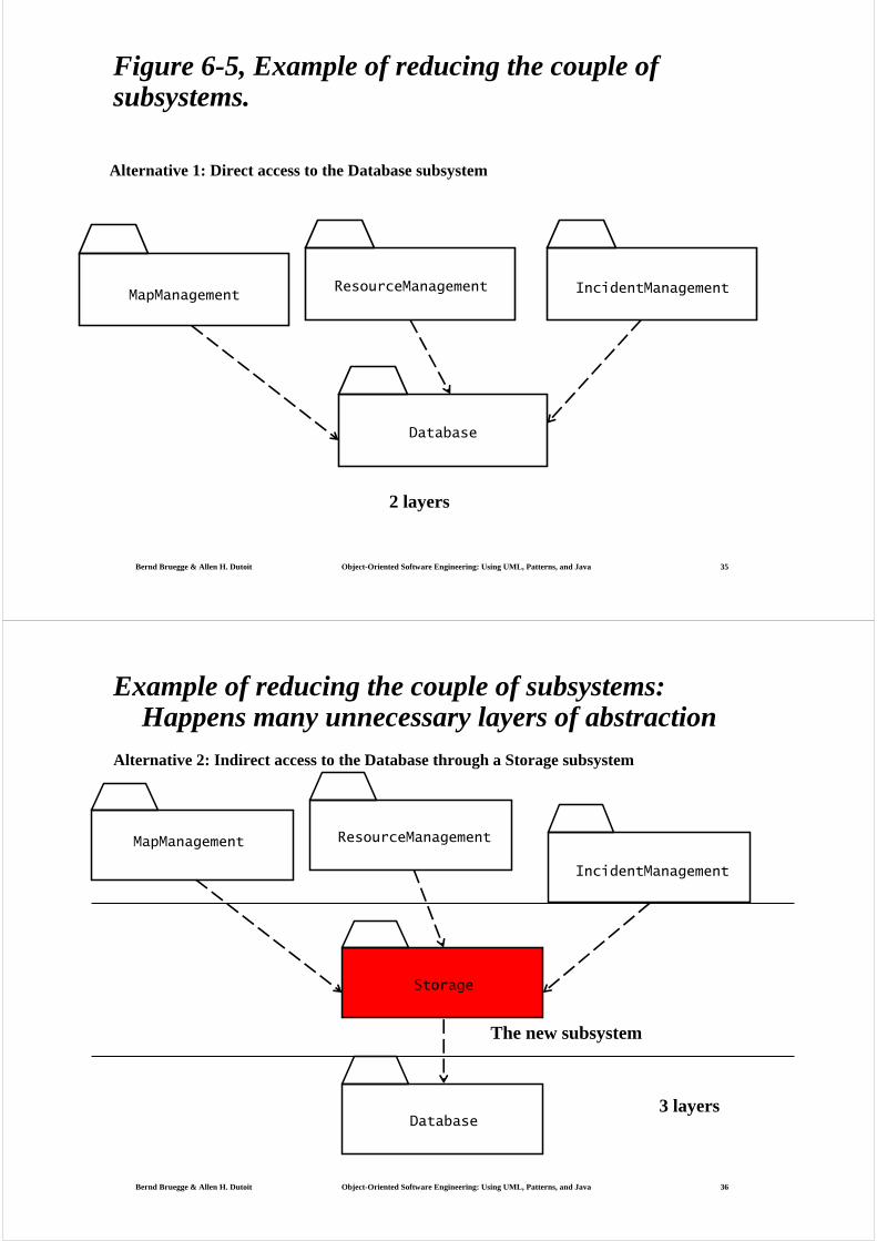
Figure 6-5, Example of reducing the couple of subsystems.
MapManagement IncidentManagement
Database
ResourceManagement
Alternative 1: Direct access to the Database subsystem
2 layers
Bernd Bruegge & Allen H. Dutoit Object-Oriented Software Engineering: Using UML, Patterns, and Java 36
Example of reducing the couple of subsystems: Happens many unnecessary layers of abstraction
MapManagement
IncidentManagement
Storage
ResourceManagement
Database
Alternative 2: Indirect access to the Database through a Storage subsystem
The new subsystem
3 layers
Bernd Bruegge & Allen H. Dutoit Object-Oriented Software Engineering: Using UML, Patterns, and Java 37
Cohesion
♦ The internal cohesion of a component may be measured in terms of the strength of binding of elements within the component.
♦ Cohesion of elements may occur on the scale of weakest (least desirable) to strongest (most desirable) in the following order:
1) Coincidental cohesion
2) Logical cohesion
3) Temporal cohesion
4) Communication cohesion
5) Sequential cohesion
6) Functional cohesion
7) Informational cohesion
Bernd Bruegge & Allen H. Dutoit Object-Oriented Software Engineering: Using UML, Patterns, and Java 38
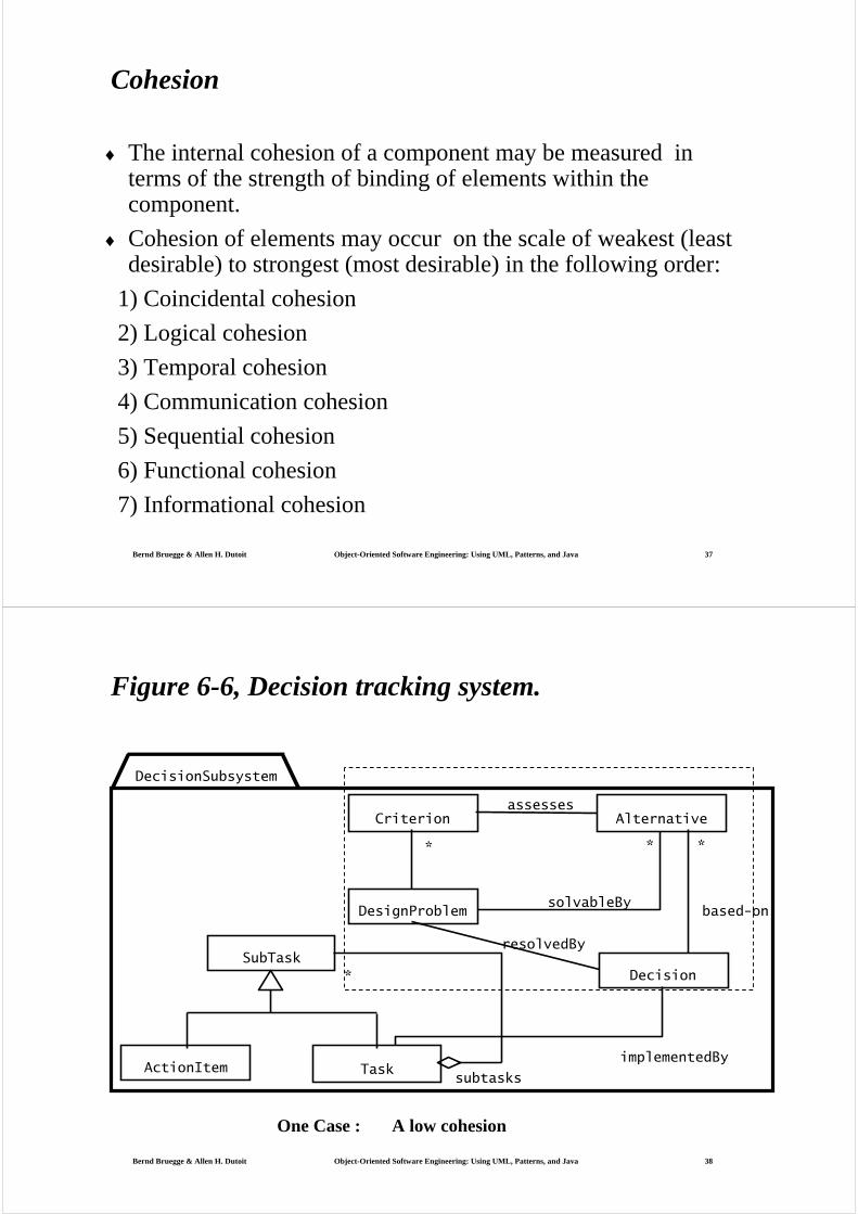
Alternative
Decision
Criterion
subtasks
*SubTask
ActionItem
DesignProblem
Task
assesses
solvableBy
resolvedBy
based-on
* * *
implementedBy
DecisionSubsystem
Figure 6-6, Decision tracking system.
One Case : A low cohesion
Bernd Bruegge & Allen H. Dutoit Object-Oriented Software Engineering: Using UML, Patterns, and Java 39
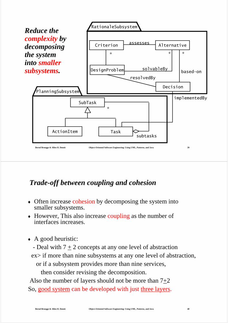
subtasks
*
assesses
solvableBy
resolvedBy
based-on
* * *
implementedBy
RationaleSubsystem
PlanningSubsystem
Criterion Alternative
Decision
DesignProblem
SubTask
ActionItem Task
Reduce the complexity by decomposing the system into smaller subsystems.
Bernd Bruegge & Allen H. Dutoit Object-Oriented Software Engineering: Using UML, Patterns, and Java 40
Trade-off between coupling and cohesion
♦ Often increase cohesion by decomposing the system into smaller subsystems.
♦ However, This also increase coupling as the number of interfaces increases.
♦ A good heuristic:- Deal with 7 + 2 concepts at any one level of abstraction
ex> if more than nine subsystems at any one level of abstraction,or if a subsystem provides more than nine services,
then consider revising the decomposition.Also the number of layers should not be more than 7+2
So, good system can be developed with just three layers.
Bernd Bruegge & Allen H. Dutoit Object-Oriented Software Engineering: Using UML, Patterns, and Java 41
Choosing Subsystems
♦ Criteria for subsystem selection: Most of the interaction shouldbe within subsystems, rather than across subsystem boundaries (High cohesion).
Does one subsystem always call the other for the service?
Which of the subsystems call each other for service?
♦ Primary Question: What kind of service is provided by the subsystems (subsystem interface)?
♦ Secondary Question:Can the subsystems be hierarchically ordered (layers)?
♦ What kind of model is good for describing layers and partitions?
Bernd Bruegge & Allen H. Dutoit Object-Oriented Software Engineering: Using UML, Patterns, and Java 42
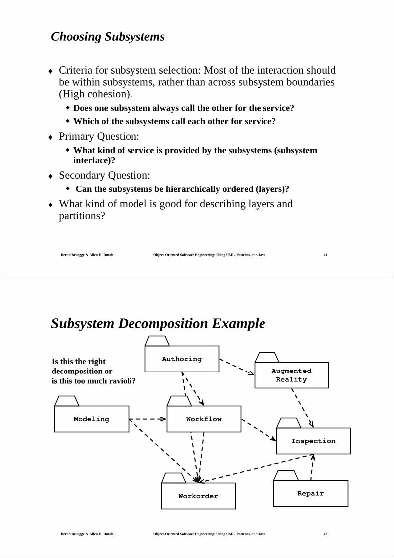
Subsystem Decomposition Example
Is this the right decomposition or is this too much ravioli?
Modeling
Authoring
Workorder Repair
Inspection
AugmentedReality
Workflow
Bernd Bruegge & Allen H. Dutoit Object-Oriented Software Engineering: Using UML, Patterns, and Java 43
Definition: Subsystem Interface Object
♦ A Subsystem Interface Object provides a service This is the set of public methods provided by the subsystem
The Subsystem interface describes all the methods of the subsystem interface object
♦ Use a Facade pattern for the subsystem interface object
Bernd Bruegge & Allen H. Dutoit Object-Oriented Software Engineering: Using UML, Patterns, and Java 44
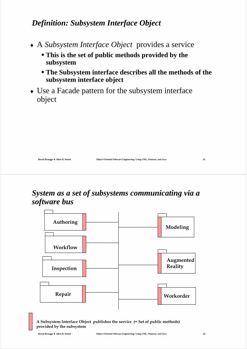
System as a set of subsystems communicating via a software bus
AuthoringModeling
AugmentedReality
WorkorderRepair
Inspection
Workflow
A Subsystem Interface Object publishes the service (= Set of public methods) provided by the subsystem
Bernd Bruegge & Allen H. Dutoit Object-Oriented Software Engineering: Using UML, Patterns, and Java 45
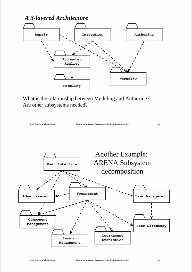
A 3-layered Architecture
What is the relationship between Modeling and Authoring?Are other subsystems needed?
Repair Inspection Authoring
AugmentedReality
Workflow
Modeling
Bernd Bruegge & Allen H. Dutoit Object-Oriented Software Engineering: Using UML, Patterns, and Java 46
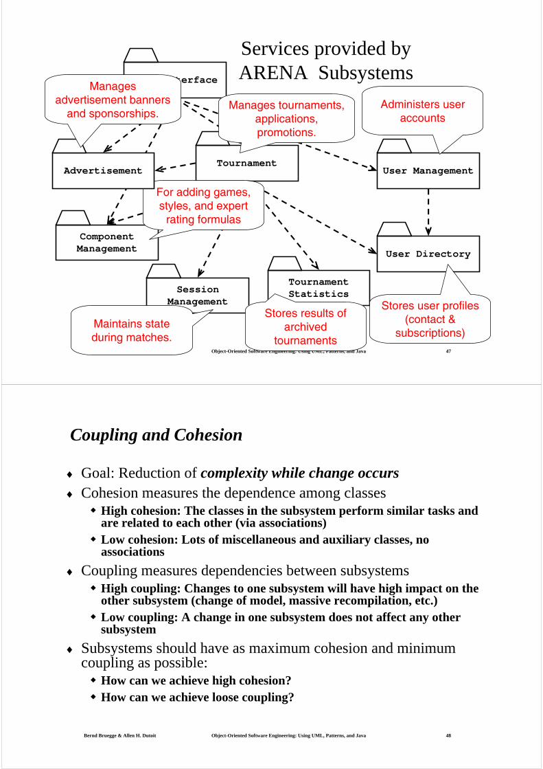
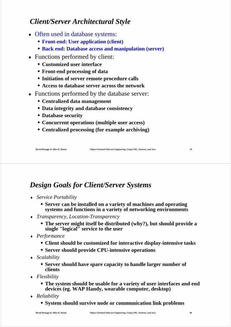
Tournament
Component Management
User Management
Tournament Statistics
User Directory
User Interface
Session Management
Another Example: ARENA Subsystem
decomposition
Advertisement
Bernd Bruegge & Allen H. Dutoit Object-Oriented Software Engineering: Using UML, Patterns, and Java 47
Tournament
Component Management
User Management
Tournament Statistics
User Directory
User Interface
Session Management
Services provided by ARENA Subsystems
For adding games, styles, and expert
rating formulas
Stores user profiles (contact &
subscriptions)
Stores results of archived
tournaments
Maintains state during matches.
Administers user accounts
Advertisement
Manages tournaments, applications, promotions.
Manages advertisement banners
and sponsorships.
Bernd Bruegge & Allen H. Dutoit Object-Oriented Software Engineering: Using UML, Patterns, and Java 48
Coupling and Cohesion
♦ Goal: Reduction of complexity while change occurs♦ Cohesion measures the dependence among classes
High cohesion: The classes in the subsystem perform similar tasks and are related to each other (via associations)Low cohesion: Lots of miscellaneous and auxiliary classes, no associations
♦ Coupling measures dependencies between subsystemsHigh coupling: Changes to one subsystem will have high impact on the other subsystem (change of model, massive recompilation, etc.)Low coupling: A change in one subsystem does not affect any other subsystem
♦ Subsystems should have as maximum cohesion and minimum coupling as possible:
How can we achieve high cohesion?How can we achieve loose coupling?

Bernd Bruegge & Allen H. Dutoit Object-Oriented Software Engineering: Using UML, Patterns, and Java 49
Partitions and Layers
Partitioning and layering are techniques to achieve low coupling.
A large system is usually decomposed into subsystems using both, layers and partitions.
♦ Partitions vertically divide a system into several independent (or weakly-coupled) subsystems that provide services on the same level of abstraction.
♦ A layer is a subsystem that provides subsystem services to a higher layers (level of abstraction)
A layer can only depend on lower layers
A layer has no knowledge of higher layers
Bernd Bruegge & Allen H. Dutoit Object-Oriented Software Engineering: Using UML, Patterns, and Java 50
F:SubsystemE:Subsystem G:Subsystem
D:SubsystemC:SubsystemB:Subsystem
A: Subsystem Layer 1
Layer 2
Layer 3
Subsystem Decomposition into Layers
♦ Subsystem Decomposition Heuristics:
♦ No more than 7+/-2 subsystemsMore subsystems increase cohesion but also complexity (more services)
♦ No more than 4+/-2 layers, use 3 layers (good)

Bernd Bruegge & Allen H. Dutoit Object-Oriented Software Engineering: Using UML, Patterns, and Java 51
Relationships between Subsystems
♦ Layer relationshipLayer A “Calls” Layer B (runtime)
Layer A “Depends on” Layer B (“make” dependency, compile time)
♦ Partition relationshipThe subsystem have mutual but not deep knowledge about each other
Partition A “Calls” partition B and partition B “Calls” partition A
Bernd Bruegge & Allen H. Dutoit Object-Oriented Software Engineering: Using UML, Patterns, and Java 52
Virtual Machine
♦ Dijkstra: T.H.E. operating system (1965)A system should be developed by an ordered set of virtual machines, each built in terms of the ones below it.
VM4
VM3
VM2
VM1C1attropr
C1attropr
C1attropr
C1attropr
C1attropr
C1attropr
C1attropr
C1attropr
Problem
Existing System

Bernd Bruegge & Allen H. Dutoit Object-Oriented Software Engineering: Using UML, Patterns, and Java 53
Virtual Machine
♦ A virtual machine is an abstraction It provides a set of attributes and operations.
♦ A virtual machine is a subsystem It is connected to higher and lower level virtual machines by "provides services for" associations.
♦ Virtual machines can implement two types of software architecture
Open and closed architectures.
Bernd Bruegge & Allen H. Dutoit Object-Oriented Software Engineering: Using UML, Patterns, and Java 54
Closed Architecture (Opaque Layering)
♦ Any layer can only invoke operations from the immediate layer below
♦ Design goal: High maintainability, flexibility
VM4
VM3
VM2
VM1C1
attr
op
C1
attr
op
C1
attr
op
C1
attr
op
C1
attr
op
C1
attr
op
C1
attr
op
C1
attr
op
C1
attr
op

Bernd Bruegge & Allen H. Dutoit Object-Oriented Software Engineering: Using UML, Patterns, and Java 55
Open Architecture (Transparent Layering)
♦ Any layer can invoke operations from any layers below
♦ Design goal: Runtime efficiency
VM4
VM3
VM2
VM1C1
attr
op
C1
attr
op
C1
attr
op
C1
attr
op
C1
attr
op
C1
attr
op
C1
attr
op
C1
attr
op
C1
attr
op
Bernd Bruegge & Allen H. Dutoit Object-Oriented Software Engineering: Using UML, Patterns, and Java 56
Properties of Layered Systems
♦ Layered systems are hierarchical. They are desirable because hierarchy reduces complexity (by low coupling).
♦ Closed architectures are more portable.
♦ Open architectures are more efficient.
♦ If a subsystem is a layer, it is often called a virtual machine.
♦ Layered systems often have a chicken-and egg problemExample: Debugger opening the symbol table when the file system needs to be debugged
G: Op. System
D: File System
A: Debugger

Bernd Bruegge & Allen H. Dutoit Object-Oriented Software Engineering: Using UML, Patterns, and Java 57
Software Architectural Styles
♦ Subsystem decompositionIdentification of subsystems, services, and their relationship to each other.
♦ Specification of the system decomposition is critical.
♦ Patterns for software architectureClient/Server
Peer-To-Peer
Repository
Model/View/Controller
Pipes and Filters
Bernd Bruegge & Allen H. Dutoit Object-Oriented Software Engineering: Using UML, Patterns, and Java 58
Client/Server Architectural Style
♦ One or many servers provides services to instances of subsystems, called clients.
♦ Client calls on the server, which performs some service and returns the result
Client knows the interface of the server (its service)
Server does not need to know the interface of the client
♦ Response in general immediately
♦ Users interact only with the client
Client
Server
service1()service2()
serviceN()…
**
requester provider
Bernd Bruegge & Allen H. Dutoit Object-Oriented Software Engineering: Using UML, Patterns, and Java 59
Client/Server Architectural Style
♦ Often used in database systems:Front-end: User application (client)Back end: Database access and manipulation (server)
♦ Functions performed by client:Customized user interfaceFront-end processing of dataInitiation of server remote procedure callsAccess to database server across the network
♦ Functions performed by the database server:Centralized data managementData integrity and database consistencyDatabase securityConcurrent operations (multiple user access)Centralized processing (for example archiving)
Bernd Bruegge & Allen H. Dutoit Object-Oriented Software Engineering: Using UML, Patterns, and Java 60
Design Goals for Client/Server Systems
♦ Service PortabilityServer can be installed on a variety of machines and operating systems and functions in a variety of networking environments
♦ Transparency, Location-TransparencyThe server might itself be distributed (why?), but should provide a single "logical" service to the user
♦ PerformanceClient should be customized for interactive display-intensive tasksServer should provide CPU-intensive operations
♦ ScalabilityServer should have spare capacity to handle larger number of clients
♦ FlexibilityThe system should be usable for a variety of user interfaces and end devices (eg. WAP Handy, wearable computer, desktop)
♦ ReliabilitySystem should survive node or communication link problems

Bernd Bruegge & Allen H. Dutoit Object-Oriented Software Engineering: Using UML, Patterns, and Java 61
Problems with Client/Server Architectural Styles
♦ Layered systems do not provide peer-to-peer communication
♦ Peer-to-peer communication is often needed
♦ Example: Database receives queries from application but also sends notifications to application when data have changed
Bernd Bruegge & Allen H. Dutoit Object-Oriented Software Engineering: Using UML, Patterns, and Java 62
Peer-to-Peer Architectural Style
♦ Generalization of Client/Server Architecture
♦ Clients can be servers and servers can be clients
♦ More difficult because of possibility of deadlocks
Peer
service1()service2()
serviceN()…
requester
provider
*
*
application1:DBUser
database:DBMS
application2:DBUser
1. updateData
2. changeNotification

Bernd Bruegge & Allen H. Dutoit Object-Oriented Software Engineering: Using UML, Patterns, and Java 63
Peer
Client Server
Bernd Bruegge & Allen H. Dutoit Object-Oriented Software Engineering: Using UML, Patterns, and Java 64
Application
Presentation
Session
Transport
Network
DataLink
Physical
Lev
el o
f ab
stra
ctio
n
Example of a Peer-to-Peer Architectural Style
♦ ISO’s OSI Reference Model
ISO = International Standard OrganizationOSI = Open System Interconnection
♦ Reference model defines 7 layers of network protocols and strict methods of communication between the layers.
♦ Closed software architecture
Layer

Bernd Bruegge & Allen H. Dutoit Object-Oriented Software Engineering: Using UML, Patterns, and Java 65
OSI model Packages and their Responsibility
♦ The Physical layer represents the hardware interface to the net-work. It allows to send() and receive bits over a channel.
♦ The Datalink layer allows to send and receive frames without error using the services from the Physical layer.
♦ The Network layer is responsible for that the data are reliably transmittedand routed within a network.
♦ The Transport layer is responsible for reliably transmitting from end to end. (This is the interface seen by Unix programmers when transmitting over TCP/IP sockets)
♦ The Session layer is responsible for initializing a connection, including authentication.
♦ The Presentation layer performs data transformation services, such as byte swapping and encryption
♦ The Application layer is the system you are designing (unless you build a protocol stack). The application layer is often layered itself.
Bernd Bruegge & Allen H. Dutoit Object-Oriented Software Engineering: Using UML, Patterns, and Java 66
Application
Presentation
Session
Transport
Network
DataLink
Physical
Frame
Packet
Bit
Connection
Format
Message
Another View at the ISO Model
• A closed software architecture
• Each layer is a UML package containing a set of objects

Bernd Bruegge & Allen H. Dutoit Object-Oriented Software Engineering: Using UML, Patterns, and Java 67
Middleware Allows Focus On The Application Layer
Application
Presentation
Session
Transport
Network
DataLink
Physical
Socket
CORBA
TCP/IP
Object
Ethernet Wire
Bernd Bruegge & Allen H. Dutoit Object-Oriented Software Engineering: Using UML, Patterns, and Java 68
Model/View/Controller
♦ Subsystems are classified into 3 different typesModel subsystem: Responsible for application domain knowledge
View subsystem: Responsible for displaying application domain objects to the user
Controller subsystem: Responsible for sequence of interactions with the user and notifying views of changes in the model.
♦ MVC is a special case of a repository architecture:Model subsystem implements the central datastructure, the Controller subsystem explicitly dictate the control flow
Controller
Model
subscribernotifier
initiator
*
repository1
1
*
View
Bernd Bruegge & Allen H. Dutoit Object-Oriented Software Engineering: Using UML, Patterns, and Java 69
Example of a File System Based on the MVC Architectural Style
Bernd Bruegge & Allen H. Dutoit Object-Oriented Software Engineering: Using UML, Patterns, and Java 70
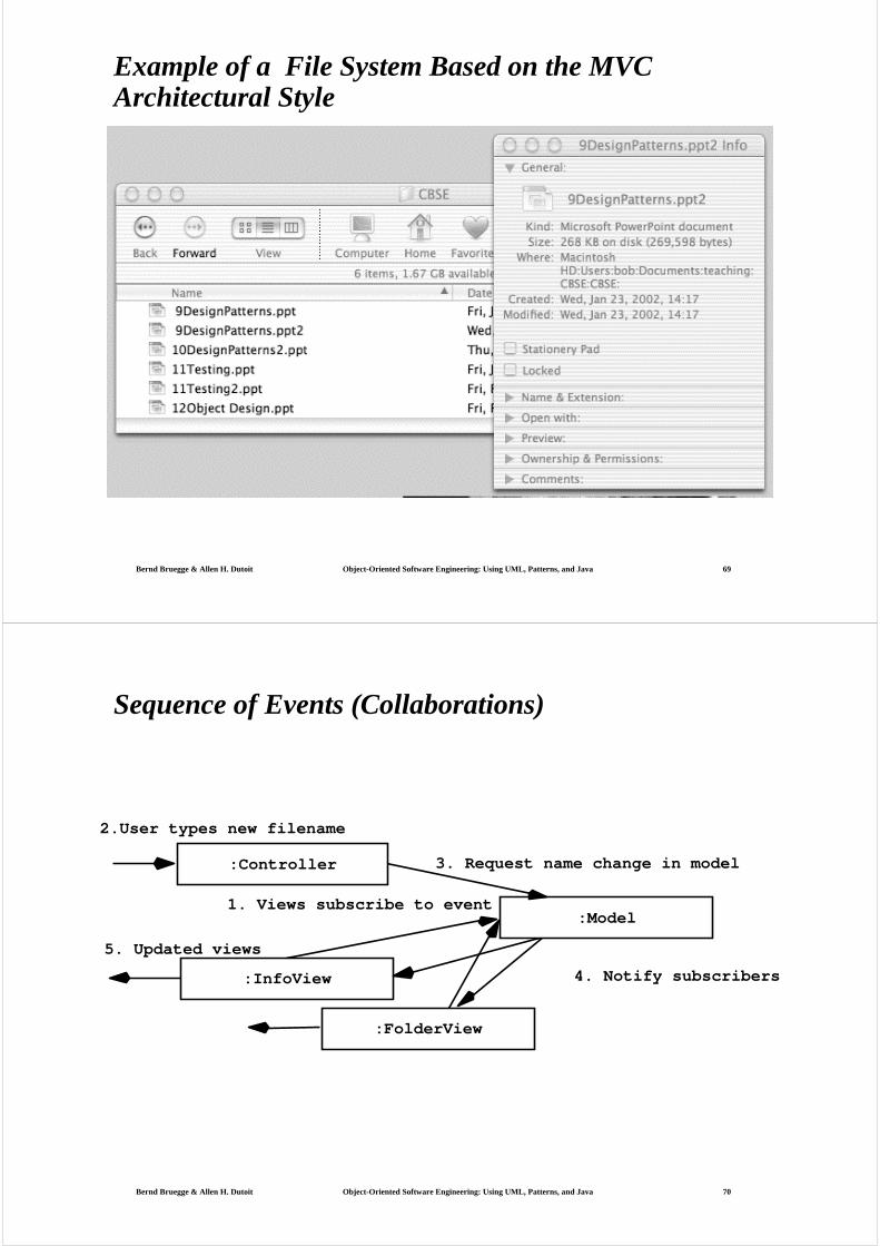
Sequence of Events (Collaborations)
:Controller
:InfoView
:Model
2.User types new filename
1. Views subscribe to event
3. Request name change in model
4. Notify subscribers
5. Updated views
:FolderView

Bernd Bruegge & Allen H. Dutoit Object-Oriented Software Engineering: Using UML, Patterns, and Java 71
Repository Architectural Style (Blackboard Architecture, Hearsay II Speech Recognition System)
♦ Subsystems access and modify data from a single data structure
♦ Subsystems are loosely coupled (interact only through the repository)
♦ Control flow is dictated by central repository (triggers) or by the subsystems (locks, synchronization primitives)
Subsystem
Repository
createData()setData()getData()searchData()
Bernd Bruegge & Allen H. Dutoit Object-Oriented Software Engineering: Using UML, Patterns, and Java 72
Examples of Repository Architectural Style
♦ Hearsay II speech understanding system (“Blackboard architecture”)
♦ Database Management Systems
♦ Modern Compilers
LexicalAnalyzer
SyntacticAnalyzerSemanticAnalyzer
CodeGenerator
Compiler
SyntacticEditor
ParseTree SymbolTable
Repository
SourceLevelDebugger
Optimizer
Bernd Bruegge & Allen H. Dutoit Object-Oriented Software Engineering: Using UML, Patterns, and Java 73
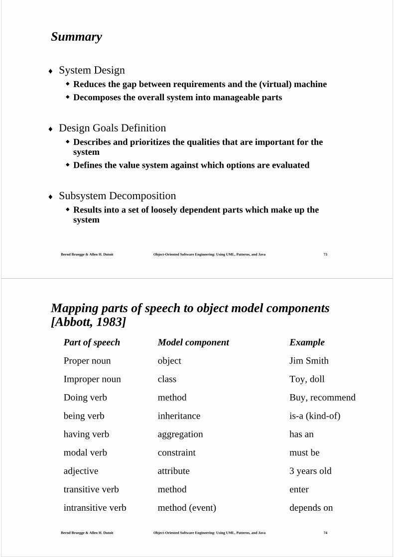
Summary
♦ System DesignReduces the gap between requirements and the (virtual) machine
Decomposes the overall system into manageable parts
♦ Design Goals DefinitionDescribes and prioritizes the qualities that are important for the system
Defines the value system against which options are evaluated
♦ Subsystem DecompositionResults into a set of loosely dependent parts which make up the system
Bernd Bruegge & Allen H. Dutoit Object-Oriented Software Engineering: Using UML, Patterns, and Java 74
Mapping parts of speech to object model components [Abbott, 1983]
Part of speech Model component Example
Proper noun object Jim Smith
Improper noun class Toy, doll
Doing verb method Buy, recommend
being verb inheritance is-a (kind-of)
having verb aggregation has an
modal verb constraint must be
adjective attribute 3 years old
transitive verb method enter
intransitive verb method (event) depends on
Bernd Bruegge & Allen H. Dutoit Object-Oriented Software Engineering: Using UML, Patterns, and Java 75
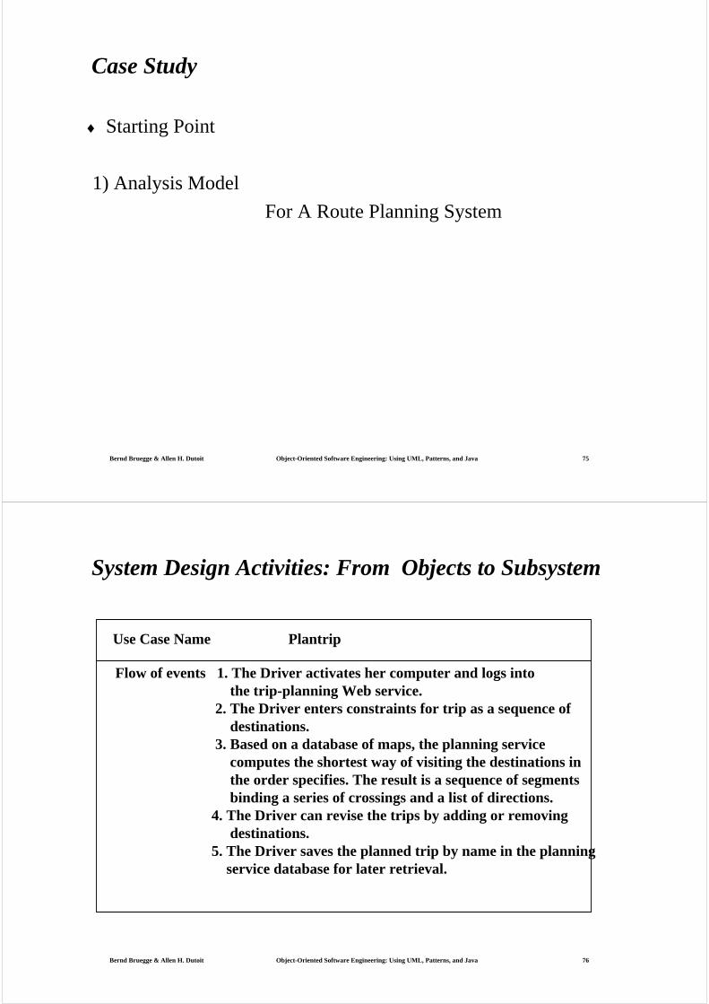
Case Study
♦ Starting Point
1) Analysis Model
For A Route Planning System
Bernd Bruegge & Allen H. Dutoit Object-Oriented Software Engineering: Using UML, Patterns, and Java 76
System Design Activities: From Objects to Subsystem
Use Case Name Plantrip
Flow of events 1. The Driver activates her computer and logs into the trip-planning Web service.
2. The Driver enters constraints for trip as a sequence ofdestinations.
3. Based on a database of maps, the planning service computes the shortest way of visiting the destinations inthe order specifies. The result is a sequence of segmentsbinding a series of crossings and a list of directions.
4. The Driver can revise the trips by adding or removing destinations.
5. The Driver saves the planned trip by name in the planningservice database for later retrieval.
Bernd Bruegge & Allen H. Dutoit Object-Oriented Software Engineering: Using UML, Patterns, and Java 77
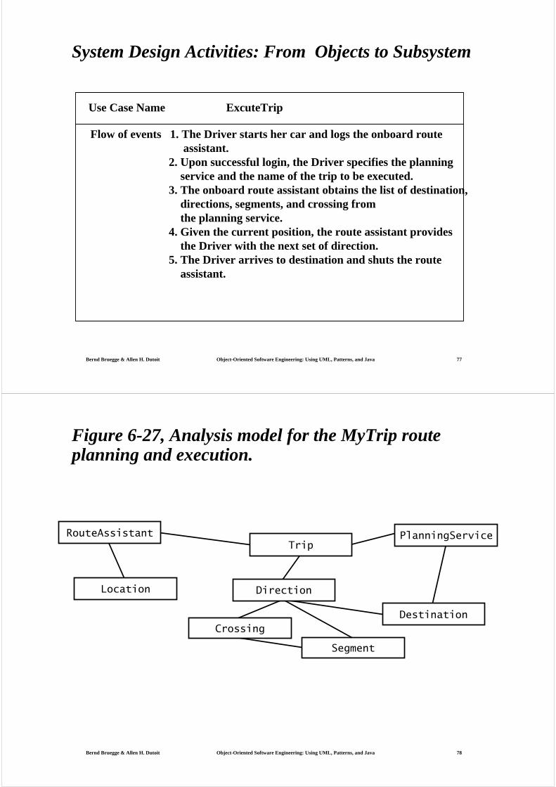
System Design Activities: From Objects to Subsystem
Use Case Name ExcuteTrip
Flow of events 1. The Driver starts her car and logs the onboard routeassistant.
2. Upon successful login, the Driver specifies the planning service and the name of the trip to be executed.
3. The onboard route assistant obtains the list of destination,directions, segments, and crossing fromthe planning service.
4. Given the current position, the route assistant provides the Driver with the next set of direction.
5. The Driver arrives to destination and shuts the route assistant.
Bernd Bruegge & Allen H. Dutoit Object-Oriented Software Engineering: Using UML, Patterns, and Java 78
Location
Segment
Crossing
Direction
Destination
TripRouteAssistant PlanningService
Figure 6-27, Analysis model for the MyTrip route planning and execution.

Bernd Bruegge & Allen H. Dutoit Object-Oriented Software Engineering: Using UML, Patterns, and Java 79
Location
Segment
Crossing
Direction
Destination
RoutingSubsystem PlanningSubsystem
TripRouteAssistant PlanningService
Figure 6-28, Initial subsystem decomposition for MyTrip.
Bernd Bruegge & Allen H. Dutoit Object-Oriented Software Engineering: Using UML, Patterns, and Java 80
Analysis Model for the Mytrip route planning and execution
RouteAssistant PlanningService
Destination
LocationTrip
Direction
CrossingSegment
Crossing: A Crossing is a geographical point where several Segments meet.Destination: A Destination represents a location where the driver wishes to go.Direction: Given a Crossing and an adjacent Segment, a Direction describes in
natural language how to steer the car onto the given Segment.Location: A Location is the position of the car as known by the onboard GPS system
the number of turns of the wheels.PlanningService: A PlanningService is a Web server that can supply a trip, linking a
number of destinations in the form of a sequence of Crossings and Segments.RouteAssistant: A RouteAssistant givens Directions to the driver, given the current
Location and upcoming Crossing.Segment: A Segment represents the road between two Crossings.Trip: A Trip is a sequence of Directions between two Destinations.
Bernd Bruegge & Allen H. Dutoit Object-Oriented Software Engineering: Using UML, Patterns, and Java 81
Nonfunctional requirements for Myrip
1) MyTrip is in contact with the PlanningService via a wireless modem. Assume that the wireless modem functions properly at the initial destination.
2) Once the trip has been started. Mytrip should give a correct directions even if modem fails to maintain a connection with the PlanningService.
3) MyTrip should minimize connection time to reduce operation costs.
4) Replanning is possible only if the connection to the PlanningService is possible.
5) The PlanningService can support at least 50 different drivers and 1,000trips.
Bernd Bruegge & Allen H. Dutoit Object-Oriented Software Engineering: Using UML, Patterns, and Java 82
Design goals for Myrip
♦ Reliability: MyTrip should be reliable [generalization of NFR 2]
♦ Fault Tolerance: Mytrip should give fault tolerant to loss of connectivity with routing service [rephrased NFR 2]
♦ Security: MyTrip should be se
♦ cure,i.e., not allow other drivers or nonauthorized uses to access a driver’s trips [deduced from application domain]
♦ Modifiability: MyTrip should be modifiable to use different routing services [anticipation of change by developers]
Bernd Bruegge & Allen H. Dutoit Object-Oriented Software Engineering: Using UML, Patterns, and Java 83
Recommended


