Chapter 2
OFDMA WiMAX Physical Layer
Ramjee Prasad and Fernando J. Velez
Abstract IEEE 802.16 physical (PHY) layer is characterized by Orthogonal
Frequency Division Multiplexing (OFDM), Time Division Duplexing, Frequency
division Duplexing, Quadrature Amplitude Modulation and Adaptive Antenna
Systems. After discussing the basics of OFDM and Orthogonal Frequency divi-
sion Multiple Access (OFDMA), scalable OFDMA is presented and supported
frequency bands, channel bandwidth and the different IEEE 802.16 PHY are
discussed. The similarities and differences between wireless MAN-SC, wireless
MAN-OFDM and wireless MAN-OFDMA PHY are finally highlighted.
2.1 Introduction
The IEEE 802.16 standard belongs to the IEEE 802 family, which applies to
Ethernet. WiMAX is a form of wireless Ethernet and therefore the whole standard
is based on the Open Systems Interconnections (OSI) reference model.
In the context of the OSI model, the lowest layer is the physical layer. It
specifies the frequency band, the modulation scheme, error-correction techniques,
synchronization between transmitter and receiver, data rate and the multiplexing
techniques.
For IEEE 802.16, Physical layer was defined for a wide range of frequencies
from 2–66 GHz. In sub frequency range of 10–66 GHz there essentially is LoS
propagation. Therefore, single carrier modulation was chosen, because of low
R. Prasad (*)
Center for TeleInFrastruktur (CTIF), Aalborg University, Niels Jernes Vej 12, DK–9220 Aalborg
Øst, Denmark
e-mail: [email protected]
R. Prasad and F.J. Velez, WiMAX Networks,DOI 10.1007/978-90-481-8752-2_2, # Springer ScienceþBusiness Media B.V. 2010
63
system complexity. Downlink channel is shared among users with TDM signals.
Subscriber unit are being allocated individual time slots. Access in uplink is being
realized with TDMA. In the 2–11 GHz bands, communications can be achieved
for licensed and non-licensed bands. The communication is also available in NLoS
conditions.
To ensure the most efficient delivery in terms of bandwidth and available
frequency spectrum, the IEEE 802.16 physical layer uses a number of legacy
technologies. These technologies include Orthogonal Frequency Division Multi-
plexing (OFDM), Time Division Duplexing (TDD), Frequency Division Duplexing
(FDD), Quadrature Amplitude Modulation (QAM), and Adaptive Antenna System
(AAS). The WiMAX physical layer is based on OFDM. OFDM is the transmission
scheme of choice to enable high speed data, video, and multimedia communications
and presently, besides WiMAX, it is used by a variety of commercial broadband
systems, including DSL, Wi-Fi, Digital Video Broadcast-Handheld (DVB-H).
Above the physical layer are the functions associated with providing service to
subscribers. These functions include transmitting data in frames and controlling
access to the shared wireless medium, and are grouped into a media access control
(MAC) layer.
This Chapter is organized as follows. Section 2.2 addresses the history, evolu-
tion and applications of OFDM. Section 2.3 presents the OFDM fundamentals by
comparing it with FDMA as well as describing OFDM signal characteristics.
Section 2.4 describes the concepts behind OFDM transmission and presents the
serial to parallel converter as well as the OFDM demodulator. The OFDM symbol
is described in Section 2.5 while Section 2.6 presents ISI and ICI mitigation.
Section 2.7 addresses spectral efficiency. Section 2.8 presents the improvements
of OFDMA and the advantages of subchannelisation. Section 2.9 and 2.10 present
the advantages and disadvantages of OFDM systems. The details on scalable
OFDMA are presented in Section 2.11, including the parameters, principles,
and the reference model. Section 2.12 addresses specific issues of PHY layer,
including WirelessHUMAN PHY, while Section 2.13 addresses WirelessMAN-
SC (single carrier) PHY. Section 2.14 covers WirelessMAN-OFDM PHY while
Section 2.15 describes WirelessMAN-OFDMA PHY. Finally, Section 2.16
presents the conclusions.
2.2 History and Development of OFDM
2.2.1 Evolution
OFDM has recently been gaining interest from telecommunications industry. It has
been chosen for several current and communications systems all over the world.
Nevertheless, OFDM had a long history of existence (Table 2.1). The first multichan-
nel modulation systems appeared in the 1950s as frequency division multiplexed
64 R. Prasad and F.J. Velez

military radio links. OFDM had been used by US military in several high frequency
military systems, such as KINEPLEX, ANDEFT and KATHRYN [1, 2].
In December 1966, Robert W. Chang outlined first OFDM scheme. This was a
theoretical way to transmit simultaneous data stream through linear band limited
channel without Inter Symbol Interference (ISI) and Inter Carrier Interference (ICI).
Chang obtained the first US patent on OFDM in 1970 [12]. Around the same time,
Saltzberg performed an analysis of the performance of the OFDM system and
concluded that the strategy should concentrate more on reducing cross talk between
adjacent channels than on perfecting the channels [6].
Until this time, we needed a large number of subcarrier oscillators to perform
parallel modulations and demodulations. This was the main reason why the OFDM
technique has taken a long time to become a prominence. It was difficult to generate
such a signal, and even harder to receive and demodulate the signal. The hardware
solution, which makes use of multiple modulators and demodulators, was some-
what impractical for use in the civil systems.
In the year 1971, Weinstein and Ebert used Discrete Fourier Transform (DFT) to
perform baseband modulation and demodulation. The use of DFT eliminated the
Table 2.1 A brief history of OFDM
Dates OFDM Landmark Achieved
1966 Chang postulated the principle of transmitting messages simultaneously through a
linear band limited channel without ICI and ISI [3]. This is considered the first
official publication on multicarrier modulation. Earlier work on OFDM was
Holsinger’s 1964 MIT dissertation [4] and some of Gallager’s early work on
waterfilling [5].
1967 Saltzberg observed that, in order to increase efficiency of parallel system, cross
talk between adjacent channels should be reduced [6].
1971 Weinstein and Ebert show that multicarrier modulation can be accomplished by
using a DFT [7].
1980 Peled and Ruiz introduced use of Cyclic Prefix (CP) or cyclic extension instead of
guard spaces [8].
1985 Cimini at Bell Labs identifies many of the key issues in OFDM transmission and
does a proof-of-concept design [9].
1990–1995 OFDM was exploited for wideband data communications over mobile radio FM
radio, DSL, HDSL, ADSL and VDSL. First commercial use of OFDM in DAB
and DVB.
1999 The IEEE 802.11 used OFDM at the physical layer. HiperLAN and HiperLAN/
2 also adopted OFDM at the physical layer.
2002 The IEEE 802.16 committee released WMAN standard 802.16 based on OFDM.
2003 The IEEE 802.11 committee releases the 802.11g standard for operation in the 2.4
GHz band. The multiband OFDM standard for ultra wideband is developed.
2004 OFDM is candidate for IEEE 802.15.3a standard for wireless PAN (MB-OFDM)
and IEEE 802.11n standard for next generation wireless LAN [33].
2005 OFDMA is candidate for the 3GPP Long Term Evolution (LTE) air interface
E-UTRA downlink [33].
2007 The first complete LTE air interface implementation was demonstrated, including
OFDM-MIMO, SC-FDMA and multi-user MIMO uplink [34].
2008 Mobile WiMAX base stations and subscriber devices were first certified by
WiMAX Forum.
2 OFDMA WiMAX Physical Layer 65

need for bank of subcarrier oscillators. These efforts paved the way for the way for
easier, more useful and efficient implementation of the system. The availability of
this technique, and the technology that allows it to be implemented on integrated
circuits at a reasonable price, has permitted OFDM to be developed as far as it has.
The process of transforming from the time domain representation to the frequency
domain representation uses the Fourier transform itself, whereas the reverse process
uses the inverse Fourier transform.
All the proposals until this moment in time used guard spaces in frequency
domain and a raised cosine windowing in time domain to combat ISI and ICI.
Another milestone for OFDM history was when Peled and Ruiz introduced Cyclic
Prefix (CP) or cyclic extension in 1980 [8]. This solved the problem of maintaining
orthogonal characteristics of the transmitted signals at severe transmission condi-
tions. The generic idea that they placed was to use cyclic extension of OFDM
symbols instead of using empty guard spaces in frequency domain. This effectively
turns the channel as performing cyclic convolution, which provides orthogonality
over dispersive channels when CP is longer than the channel impulse response [1].
It is obvious that introducing CP causes loss of signal energy proportional to length
of CP compared to symbol length but, in turn, it facilitates a zero ICI advantage
which pays off.
By this time, inclusion of FFT and CP in OFDM system and substantial
advancements in Digital Signal Processing (DSP) technology made it an impor-
tant part of telecommunications landscape. In the 1990s, OFDM was exploited
for wideband data communications over mobile radio FM channels, High-bit-
rate Digital Subscriber Lines (HDSL at 1.6 Mbps), Asymmetric Digital Sub-
scriber Lines (ADSL up to 6 Mbps) and Very-high-speed Digital Subscriber
Lines (VDSL at 100 Mbps).
The first commercial use of OFDM technology was made in Digital Audio
Broadcasting (DAB).The development of DAB started in 1987 and was standar-
dized in 1994. DAB services started in 1995 in UK and Sweden.
The development of Digital Video Broadcasting (DVB) was started in 1993.
DVB along with High-Definition TeleVision (HDTV) terrestrial broadcasting stan-
dard was published in 1995. At the dawn of the twentieth century, several Wireless
Local Area Network (WLAN) standards adopted OFDM on their physical layers.
Development of European WLAN standard HiperLAN started in 1995. HiperLAN/2
was defined in June 1999 which adopts OFDM in physical layer.
OFDM technology is also well positioned to meet future needs for mobile
packet data traffics. It is emerging as a popular solution for wireless LAN, and
also for fixed broad-band access. OFDM has successfully replaced DSSS for
802.11a and 802.11g. Perhaps of even greater importance is the emergence of
this technology as a competitor for future fourth Generations (4G) wireless
systems. These systems, expected to emerge by the year 2010, promise to at last
deliver on the wireless ‘Nirvana’ of anywhere, anytime, anything communica-
tions [14]. It is expected that OFDM will become the chosen technology in most
wireless links worldwide [13] and it will certainly be implemented in 4G radio
mobile systems.
66 R. Prasad and F.J. Velez

2.2.2 Applications of OFDM
OFDM has been incorporated into four basic applications: (1) Digital Audio
Broadcasting (DAB); (2) Digital Video Broadcasting (DVB), over the terrestrial
network Digital Terrestrial Television Broadcasting (DTTB); (3) Magic WAND
(Wireless ATM Network Demonstrator); and (4) IEEE 802.11a/HiperLAN2 and
MMAC WLAN Standards.
DAB and DVD were the first standards to use OFDM. Next Magic WAND was
introduced, which demonstrated the viability of OFDM. Lastly, and most impor-
tantly, the most recent 5 GHz applications evolved which were the first to use
OFDM in packet-based wireless communications. Few of the OFDM application
and their details based on the type of wireless access technique are summarized in
Table 2.2.
2.3 OFDM Fundamentals
2.3.1 OFDM Versus FDM
Orthogonal Frequency Division Multiplexing is an advanced form of Frequency
Division Multiplexing (FDM) where the frequencies multiplexed are orthogonal to
each other and their spectra overlap with the neighbouring carriers. As shown in the
Fig. 2.1 the subcarriers never overlap for FDM. In contrast to FDM, OFDM is based
on the principle of overlapping orthogonal sub carriers.
The spectral efficiency of OFDM system as compared to FDMA is depicted in
the Fig. 2.2. The overlapping multicarrier technique can achieve superior band-
width utilization. There is a huge difference between the conventional non-over-
lapping multicarrier techniques such as FDMA and the overlapping multicarrier
technique such as OFDM.
In frequency division multiplex system, many carriers are spaced apart. The
signals are received using conventional filters and demodulators. In these receivers
guard bands are introduced between each subcarriers resulting into reduced spectral
efficiency. But in an OFDM system it is possible to arrange the carriers in such a
Table 2.2 Wireless systems using OFDM [10]
Application WMAN WLAN WPAN
Technology OFDM OFDM OFDM
Cell Radius 1–20 km up to 300 m few tens of meter
Mobility High and low Low very low
Freq Band 2–66 GHz 2–5 GHz 5–10 GHz
Data Rate Few Mbps up to 100 Mbps up to 10 Mbps
Deployment IEEE 802.16a, d, e,
WiMAX, 3GPP-LTE
IEEE 802.11a, g,
HiperLAN2
IEEE 802.15,
Zig-Bee
2 OFDMA WiMAX Physical Layer 67

fashion that the sidebands of the individual subcarriers overlap and the signals are
still received without adjacent carrier interference. The main advantage of this
concept is that each of the radio streams experiences almost flat fading channel. In
slowly fading channels the inter-symbol interference (ISI) and inter-carrier inter-
ference(ICI) is avoided with a small loss of energy using cyclic prefix.
In order to assure a high spectral efficiency the subchannel waveforms must have
overlapping transmit spectra. But to have overlapping spectra, subchannels need to
Ch.1
Ch.2 Ch.3 Ch.4 Ch.5 Ch.6 Ch.7 Ch.8 Ch.9 Ch.10
Saving of bandwidth
Ch.3 Ch.5 Ch.7 Ch.9Ch.2 Ch.4 Ch.6 Ch.8 Ch.10
Ch.1
Conventional multicarrier techniques
Orthogonal multicarrier techniques
50% bandwidth saving
frequency
frequency
Fig. 2.1 Concept of OFDM signal
f–2R/3 –R/3 R/3 2R/3
f
f–3R/4 –R/4 R/4 3R/4
f–R R –R –R/3 R/3 2R
f–R R
f–R R
N=1 N=2 N=3
B = 2R
B=2R
B = 2R
B = 3/2R
B = 2R
B = 4/3R
FDMA
OFDM
Fig. 2.2 Spectrum efficiency of OFDM compared to FDMA
68 R. Prasad and F.J. Velez

be orthogonal. Orthogonality is a property that allows the signals to be perfectly
transmitted over a common channel and detected without interference. Loss of
orthogonality results in blurring between the transmitted signals and loss of infor-
mation. For OFDM signals, the peak of one sub carrier coincides with the nulls of
the other sub carriers. This is shown in Fig. 2.3. Thus there is no interference from
other sub carriers at the peak of a desired sub carrier even though the sub carrier
spectrums overlap. OFDM system avoids the loss in bandwidth efficiency prevalent
in system using non orthogonal carrier set.
2.3.2 OFDM Signal Characteristics
An OFDM signal consists of N orthogonal subcarriers modulated by N parallel data
streams, Fig. 2.4. The data symbols (dn,k ) are first assembled into a group of block
size N and then modulated with complex exponential waveform {fk(t)}. Aftermodulation they are transmitted simultaneously as transmitter data stream.
The total continuous-time signal consisting of OFDM block is given by
xðtÞ ¼X1n¼�1
XN�1
k¼0
dn; k’kðt� nTdÞ" #
(2.1)
Frequency
Magnitude
Subcarrier Peaks
Subcarrier Nulls
Fig. 2.3 Orthogonal subcarriers in multicarrier systems (OFDM)
2 OFDMA WiMAX Physical Layer 69

where, fk(t) represents each baseband subcarrier and is given by
’kðtÞ ¼ e j2pfk t
0
�t 2 0; Td½ �otherwise
(2.2)
–5 –4 –3 –2 –1 0 1 2 3 4 5
–5 –4 –3 –2 –1 0 1 2 3 4 5
–0.4
–0.2
0
0.2
0.4
0.6
0.8
1
Samples
Rel
ativ
e A
mpl
itud
e
0
1
–0.4
–0.2
0.2
0.4
0.6
0.8
Sample Duration
Rel
ativ
e A
mpl
itud
e
Fig. 2.4 Spectra for OFDM subcarriers
70 R. Prasad and F.J. Velez
where dn,k is the symbol transmitted during nth timing interval using kth subcarrier,Td is the symbol duration, N is the number of OFDM subcarriers and fk is kth
subcarrier frequency, which is calculated as fk ¼ fo þ kTd; k ¼ 0 . . .N � 1. Note that
f0 is the lowest frequency used.
2.4 OFDM Transmission
2.4.1 Concept
The OFDM based communication systems transmit multiple data symbols simulta-
neously using orthogonal subcarriers .The principle behind the OFDM system is to
decompose the high data stream of bandwidthW into N lower rate data streams and
then to transmit them simultaneously over a large number of subcarriers. Value of Nis kept sufficiently high to make the individual bandwidth (W/N) of subcarriersnarrower than the coherence bandwidth (Bc) of the channel. The flat fading experi-
enced by the individual subcarriers is compensated using single tap equalizers.
These subcarriers are orthogonal to each other which allows for the overlapping of
the subcarriers. The orthogonality ensures the separation of subcarriers at the
receiver side. As compared to FDMA systems, which do not allow spectral over-
lapping of carriers, OFDM systems are more spectrally efficient.
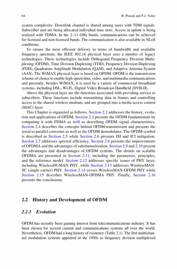
OFDM transmitter and receiver systems are described in Figs. 2.5 and 2.6.
At the transmitter, the signal is defined in the frequency domain. Forward Error
Control/Correction (FEC) coding and interleaving block is used to obtain the
robustness needed to protect against burst errors.
The modulator transforms the encoded blocks of bits into a vector of complex
values, Fig. 2.7. Group of bits are mapped onto a modulation constellation produc-
ing a complex value and representing a modulated carrier. The amplitudes and
phases of the carriers depend on the data to be transmitted. The data transitions are
synchronized at the carriers, and may be processed together, symbol by symbol.
BITS
ErrorCorrectioncoding andInterleaving
SymbolMapping
(datamodulation)
Pilot symbolinsertion
Serial-to-parallel
OFDMModulation
via FFTDAC
IQModulation
and up-converter
Basebandtransmitted
signal
CP
Complexdata
constellations
RF
Fig. 2.5 OFDM transmitter
2 OFDMA WiMAX Physical Layer 71

As the OFDM carriers are spread over a frequency range, chances are there that
some frequency selective attenuation occurs on a time varying basis. A deep fade on
a particular frequency may cause the loss of data on that frequency for that given
time, thus some of the subcarriers can be strongly attenuated and that will cause
burst errors. In these situations, FEC in COFDM can fix the errors [15]. An OFDM
system with addition of channel coding and interleaving is referred to as Coded
OFDM (COFDM). An efficient FEC coding in flat fading situations leads to a
very high coding gain. In a single carrier modulation, if such a deep fade occurs, too
many consecutive symbols may be lost and FEC may not be too effective in
recovering the lost data.
In a digital domain, binary input data is collected and FEC coded with schemes
such as convolutional codes. The coded bit stream is interleaved to obtain diversity
gain. Afterwards, a group of channel coded bits are gathered together (1 for BPSK, 2 for
QPSK, 4 for QPSK, etc.) and mapped to the corresponding constellation points.
x(t)S
dn,0
ejw0t
ejwN–1t
dn,N–1
Fig. 2.7 OFDM modulator
Dataconversionand I/Q
demodulation
Symboldemapping
(datademodulation)
OFDMDemodulation
via IFFT
Parallel -toSerial-
ChannelEstimationbased on
Pilot symbol
ADC
Error correctiondecodingand De-
interleaving
CarrierSynchronization
TimeSynchronization
ReceivedComplex dataconstellations
Received Signalat Baseband
CPO/PBinarydata
Fig. 2.6 OFDM receiver
72 R. Prasad and F.J. Velez

2.4.2 Serial to Parallel Converter
Data to be transmitted is typically in the form of a serial data stream. Serial to
parallel conversion block is needed to convert the input serial bit stream to the data
to be transmitted in each OFDM symbol. The data allocated to each symbol
depends on the modulation scheme used and the number of subcarriers. For
example, in case a subcarrier modulation of 16-QAM each subcarrier carries
4 bits of data, and so for a transmission using 100 subcarriers the number of bits
per symbol would be 400.
During symbol mapping the input data is converted into complex value constel-
lation points, according to a given constellation. Typical constellations for wireless
applications are, BPSK, QAM, and 16 QAM. The amount of data transmitted on
each subcarrier depends on the constellation. Channel condition is the deciding
factor for the type of constellation to be used. In a channel with high interference a
small constellation like BPSK is favourable as the required signal-to-noise-ratio
(SNR) in the receiver is low. For interference free channel a larger constellation is
more beneficial due to the higher bit rate. Known pilot symbols mapped with known
mapping schemes can be inserted at this moment.
Cyclic prefix is inserted in every block of data according to the system specifi-
cation and the data is multiplexed to a serial fashion. At this point of time, the data
is OFDM modulated and ready to be transmitted.
A Digital-to-Analogue Converter (DAC) is used to transform the time domain
digital data to time domain analogue data. RF modulation is performed and the
signal is up-converted to transmission frequency. After the transmission of OFDM
signal from the transmitter antenna, the signals go through all the anomaly and
hostility of wireless channel. After the receiving the signal, the receiver down-
converts the signal; and converts to digital domain using Analogue-to-Digital Con-
verter (ADC). At the time of down-conversion of received signal, carrier frequency
synchronization is performed. After ADC conversion, symbol timing synchroniza-
tion is achieved. An FFT block is used to demodulate the OFDM signal. After that,
channel estimation is performed using the demodulated pilots. Using the estima-
tions, the complex received data is obtained which are de-mapped according to
the transmission constellation diagram. At this moment, FEC decoding and de-
interleaving are used to recover the originally transmitted bit stream.
OFDM is tolerant to multi path interference. A high peak data rate can be
achieved by using higher order modulations, such as 16 QAM and 64 QAM,
which improve the spectral efficiency of the system.
2.4.3 Demodulator
The OFDM demodulator is shown in the form of a simplified block diagram is
shown in Fig. 2.8. The orthogonality condition of the signals is based orthogonality
of subcarriers {fk(t)}, defined by:
2 OFDMA WiMAX Physical Layer 73

Z<
’kðtÞ’�l ðtÞdt ¼ Tddðk � lÞ ¼ Td
0
�k ¼ lotherwise
(2.3)
The demodulator satisfies the above condition for orthogonality of the subcarriers.
2.5 OFDM Symbol Description
OFDM boosts throughput by using several subcarriers in parallel while multiplex-
ing data over the set of subcarriers. Inverse-Fourier-transforming (IFT) creates the
OFDM waveform. This time duration is referred to as the useful symbol time Tsym.A copy of the last TCP of the useful symbol period, termed Cyclic Prefix (CP), is
used to mitigate multipath, while maintaining the orthogonality of the tones.
Figure 2.9 illustrates this structure in the time domain.
The frequency domain description includes the basic structure of an OFDM
symbol (Fig. 2.10).
An OFDM symbol shown in Fig. 2.9 is made up from subcarriers, the number of
which determines the FFT size used. There are three subcarrier types: (1) data
subcarriers, for data transmission, (2) pilot subcarriers, for various estimation
purposes, and (3) null subcarriers, for no transmission at all, for guard bands, non-
active subcarriers and for the DC subcarrier.
2.6 ISI and ICI Mitigation
Two types of difficulties arise when a signal is transmitted through a time-
dispersive channel. First, channel dispersion destroys the orthogonality between
subcarriers and cause intercarrier interference (ICI) for the signal. Second, the
dn,0
x(t)
Td
Td
e —jw0t
e —jNw0t
dn,N–1
(•)Td
∫
(•)Td
∫
Fig. 2.8 OFDM demodulator
74 R. Prasad and F.J. Velez

system may sometimes transmit multiple OFDM symbols in a series causing
intersymbol interference (ISI) between successive OFDM symbols. Guard intervals
were proposed as the solution. A guard interval is defined by an empty space
between two OFDM symbols, which serves as a buffer for the multipath reflection.
When guard bands are inserted between successive OFDM symbols avoids ISI but
cannot cope with the loss of the subcarrier orthogonality.
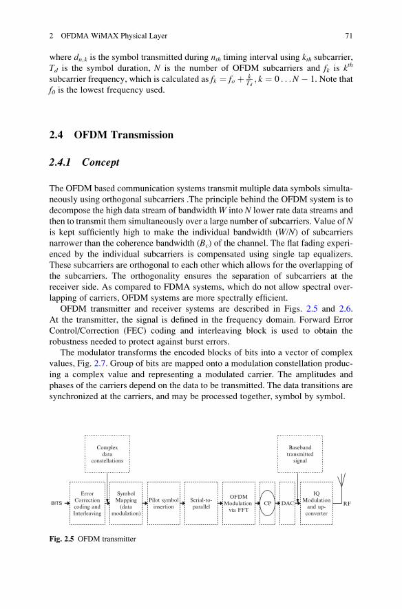
This problem was addressed by Peled and Ruiz, in 1980, by introducing cyclic
prefix (CP) instead of guard interval between successive OFDM symbols. CP is a
copy of the last part of OFDM symbol which is appended to front the transmitted
OFDM symbol. The cyclic prefix preserves the orthoganility of the subcarriers and
prevents ISI between successive OFDM symbols. CP helps to maintain orthogonal-
ity between the sub carriers. The interval must be chosen to be larger than the
expected maximum delay spread, such that multi path reflection from one symbol
would not interfere with another.
As shown in the Fig. 2.11, CP still occupies the same time interval as guard
period but, in turn, ensures that the delayed replicas of the OFDM symbols will
always have a complete symbol within the FFT interval. Thus, the transmitted
signal is still periodic and this periodicity plays a very significant role as this helps
maintaining the orthogonality. In a Fourier transform, all the resultant components
of the original signal are orthogonal to each other. CP makes sure that subsequent
subcarriers are orthogonal to each other.
Guard BandChannel
Guard Band
Pilot SubcarriersDC SubcarrierData Subcarriers
Fig. 2.10 OFDM frequency description (From [20])
TsymTCP
Ttotal
Fig. 2.9 OFDM symbol time
structure (From [19])
2 OFDMA WiMAX Physical Layer 75
At the receiver side, CP is removed before any processing starts. As long as the
length of CP interval is larger than maximum expected delay spread, all reflections
of previous symbols are removed and orthogonality is restored. The orthogonality is
lost when the delay spread is larger than length of CP interval.
Although the generated signals are always orthogonal, inserting CP has its own
cost. Part of signal energy is lost since it carries no information. The loss may be
calculated by
SNRloss CP ¼ �10log10 1� TCPTsym
� �(2.4)
where TCP is the interval length of CP and Tsym is the OFDM symbol duration.
The total symbol duration is
Ttotal ¼ TCP þ Tsym: (2.5)
The advantage gained by introducing CP is the zero ICI and ISI (although part of
the signal energy is lost). Thus, CP combats two main problems of signal transmis-
sion, first it removes the effect of ISI, and second, by maintaining orthogonality, it
completely removes the ICI.
Data part of OFDM symbol
Complete OFDM symbol
End of symbol is prependedto the beginning
Guard time FFT time
Delay Spread No ISI
OFDM Symbol time
Fig. 2.11 Use of cyclic prefix to combat ISI and ICI
76 R. Prasad and F.J. Velez

2.7 Spectral Efficiency
Figure 2.2 illustrates the different between FDMA and OFDM systems. In the
case of OFDM, an higher better spectral efficiency is achieved by maintaining
orthogonality between the subcarriers. If orthogonality is maintained between
different subchannels during transmission, then it is possible to separate the signals
very easily at the receiver side. This is ensured by classical FDM by inserting guard
bands between sub channels. These guard bands keep the subchannels far enough so
that separation of different subchannels is possible. Naturally, inserting guard bands
results to inefficient use of spectral resources.
In OFDM, orthogonality makes it possible in OFDM to arrange the subcarriers in
such a way that the sidebands of the individual carriers overlap and still the signals
are received at the receiver without being interfered by ICI. The receiver acts as a
bank of demodulators, translating each subcarrier down to DC, with the resulting
signal integrated over a symbol period to recover raw data. If the other subcarriers
all down converted to the frequencies that, in the time domain, have a whole
number of cycles in a symbol period Tsym, then the integration process results
in zero contribution from all other carriers. As a consequence, the subcarriers
are linearly independent (i.e., orthogonal) if the carrier spacing is a multiple
of 1/Tsym [18].
2.8 Orthogonal Frequency Division Modulation Access
2.8.1 Improvements
In the previous section, we discussed the OFDM as a multiplexing scheme that
provides better spectral efficiency and immunity to multipath fading. The OFDM
system is also simpler to design based on FFT/IFFT method. These advantages are
further extended for multiple access schemes by assigning a subset of subcarriers or
tones of OFDM to individual users. This multiple access technique is termed as
OFDMA. The allocation of subsets of tones to various users allows for simulta-
neous transmission of data from multiple users, allowing for sharing the physical
medium. Although this technique looks very much like FDMA, the large guard
bands required in FDMA are not needed in OFDMA.
2.8.2 Subchannelization
In OFDMA, the active subcarriers are divided into subsets of subcarriers. Each
subset represents a subchannel, as shown in the Fig. 1.2. These sub-carriers that
2 OFDMA WiMAX Physical Layer 77

form a single subchannel need not be adjacent. Thus, an OFDM symbol is sub-
divided into several subchannels by grouping the subcarriers. In the DL, a single
subchannel may be intended for different receivers whereas, in the uplink, a
transmitter may be assigned one or more subchannels, and several transmitters
may transmit simultaneously.
2.8.3 OFDMA Subchannelization: Its advantages to WiMAX
In OFDMA, subchannelization defines subchannels that can be allocated to
subcarrier stations depending on their channel conditions and data requirements.
Several SS can transmit in the same time slot over several subchannels. Depend-
ing on the channel conditions and data requirements modulation and coding is
set individually for each subscriber. The transmitter power can be adapted
separately as well, which optimizes the use of network resources. Because of
subchannelization OFDMA signals are more complex than OFDM ones but offer
better performance and scalability. This feature is very useful for WiMAX BSs.
By using subchannelization, within the same time slot, the BS is able to allocate
more transmitter power to those SSs with lower SNR and less power to the ones
with higher SNR. Subchannelization also enables the BS to allocate higher
power to subchannels assigned to indoor SSs, which results in better in-building
coverage.
Subchannelization in the uplink saves the power of the user device by concen-
trating power to the selected subchannels allocated to it. This power saving feature
is indeed very useful for battery powered SSs.
Subchannelisation uses orthogonal frequency-division multiple access with a
2048-point transform [11] and is designed for NLoS operation in the frequency
bands below 11 GHz. For licensed bands, channel bandwidths allowed is limited
to the regulatory provisioned bandwidth divided by any power of 2 no less than
1.0 MHz. The concept is shown in Fig. 2.12.
2.9 Advantages of OFDM Systems
The following advantages of OFDM may be identified:
l OFDM is spectrally efficient; IFFT/FFT operation ensures that sub-carriers do
not interfere with each other.l OFDM has an inherent robustness against narrowband interference. Narrowband
interference will affect at most a couple of subchannels. Information from the
affected subchannels can be erased and recovered via the forward error correc-
tion (FEC) codes.l Equalization is very simple compared to Single-Carrier systems.
78 R. Prasad and F.J. Velez

l The OFDM transmitter is low cost as the design is simple because the modula-
tion technique is simpler implementation based on a highly optimized FFT/IFFT
block. Also OFDM transmitters posses the ability to implement the mapping of
bits to unique carriers via the use of the Inverse Fast Fourier Transform (IFFT)
[13].l As the OFDM transmitter simplifies the channel effect, thus a simple receiver
structure is enough for recovering transmitted data. If we use coherent modu-
lation schemes, then very simple channel estimation (and/or equalization) is
needed. In turn, no channel estimator is needed if differential modulation
schemes are used [14].l In a relatively slow time-varying channel, it is possible to significantly enhance
the capacity by adapting the data rate per subcarrier according to the value of
SNR for that particular subcarrier [1].l In contrast to CDMA, OFDM receiver collects signal energy in frequency
domain, thus it is able to protect energy loss at frequency domain.l OFDM is more resistant to frequency selective fading than single carrier
systems.l The orthogonality preservation procedures in OFDM are much simpler com-
pared to CDMA or TDMA techniques even in very severe multipath conditions.
Time
OFDM
Sub
-Car
rier
s
Time
Sub
-Cha
nnel
s
Pre
ambl
e D
L
FC
H
Pre
ambl
e D
L
FC
H
Pre
ambl
e U
L
DL part UL part
OFDMDL part UL part
User1
User2
User3
User4
User5
Fig. 2.12 OFDMA versus OFDM: subchannels and sub-carriers
2 OFDMA WiMAX Physical Layer 79
l OFDM can be used for high-speed multimedia applications with lower service
cost.l OFDM can also support dynamic packet access.l Ability to comply with world-wide regulations: Bands and tones can be dyna-
mically turned on/off to comply with changing regulations. Single frequency
networks are possible in OFDM, which is especially attractive for broadcast
applications.l Smart antennas can be integrated with OFDM. MIMO systems and space-time
coding can be realized on OFDM and all the benefits of MIMO systems can be
obtained easily. Adaptive modulation and tone/power allocation are also realiz-
able on OFDM.
2.10 Disadvantages of OFDM Systems
2.10.1 Strict Synchronization Requirement
OFDM is highly sensitive to time and frequency synchronization errors, especially
at frequency synchronization errors, everything can go wrong. Demodulation of an
OFDM signal with an offset in the frequency can lead to a high bit error rate. These
are two sources of synchronization errors. One is caused by the difference between
local oscillator frequencies in transmitter and receiver, while the other is due to the
relative motion between the transmitter and receiver that gives Doppler spread.
Local oscillator frequencies at both points must match as closely as they can. For
higher number of subchannels, the matching should be even more perfect. Motion
of transmitter and receiver causes the other frequency error. So, OFDM may show
significant performance degradation at high-speed moving vehicles [12]. To opti-
mize the performance of an OFDM link, accurate synchronization is therefore of
prime importance.
Synchronization needs to be done into three aspects: symbol, carrier frequency
and sampling frequency synchronization. A description of synchronization proce-
dures is given in [1].
2.10.2 Peak-to-Average Power Ratio
Peak to Average Power Ratio (PAPR) is proportional to the number of sub-
carriers used for OFDM systems. The PAPR for an OFDM system is given by
10 log (N) where N is the number of subcarriers. For example for a 48 subcarrier
system, such as 802.11a where 48 out of 64 subcarriers are active, the PAPR is
approximately 17 dB. Therefore OFDM system with large number of sub-carriers
will thus have a very large PAPR when the sub-carriers add up coherently. An
80 R. Prasad and F.J. Velez

Large PAPR of a system makes the implementation of Digital-to-Analog Con-
verter (DAC) and Analog-to-Digital Converter (ADC) to be extremely difficult.
The design of RF amplifier also becomes increasingly difficult as the PAPR
increases.
To mitigate the effect of such large PAPRs on performance degradation of
the OFDM system, the design of the OFDM system needs to incorporate costly
RF hardware, such as efficient and large linear dynamic range power amplifiers.
Incorporating costly RF hardware, however, increases the cost of the OFDM
system. There are basically three techniques that are used at present to reduce
PAPR, they are Signal Distortion Techniques, Coding Techniques and finally the
Scrambling Technique.
2.10.3 Co-channel Interference Mitigation in Cellular OFDM
A conventional OFDM system exhibits performance degradation due to frequency
coherence of the channel. The closer the spacing between the adjacent subcarriers
or the narrower the required coherence bandwidth is. In many channels, adjacent
subcarriers will fall within the coherence bandwidth and will thereby experience
flat fading.
In cellular communications systems, co-channel interference (CCI) is combated
by combining adaptive antenna techniques, such as sectorization, directive antenna,
antenna arrays, etc. Some are just avoidance techniques but others may be truly
interference cancellation methodologies. Using OFDM in cellular systems will give
rise to CCI. Similarly with the traditional techniques, with the aid of beam steering, it
is possible to focus the receiver’s antenna beam on the served user, while attenuating
the co-channel interferers. This is significant since OFDM is sensitive to CCI.
2.11 Scalable OFDMA
2.11.1 Parameters and Principles
When designing OFDMA wireless systems the optimal choice of the number of
subcarriers per channel bandwidth is a tradeoff between protection against multi-
path, Doppler shift, and design cost/complexity. Increasing the number of subcar-
riers leads to better immunity to the inter-symbol interference (ISI) caused by
multipath (due to longer symbols); in turn, it increases the cost and complexity of
the system (it leads to higher requirements for signal processing power and power
amplifiers with the capability of handling higher peak-to-average power ratios).
Having more subcarriers also results in narrower subcarrier spacing and therefore
the system becomes more sensitive to Doppler shift and phase noise. Calculations
2 OFDMA WiMAX Physical Layer 81

show that the optimum tradeoff for mobile systems is achieved when subcarrier
spacing is about 11 kHz [28].
Unlike many other OFDM-based systems such as IEEE 802.11a/g WLANs, the
802.16 standard supports variable bandwidth sizes for NLoS operations. In order to
keep optimal subcarrier spacing, the FFT size should scale with the bandwidth. This
concept is introduced in Scalable OFDMA (SOFDMA) [23, 28]. The concept of
scalability was introduced to the IEEE 802.16 WirelessMAN OFDMAmode by the
802.16 Task Group e (TGe). A scalable physical layer enables standard-based
solutions to deliver optimum performance in channel bandwidths, ranging from
1.25 MHz to 20 MHz with fixed subcarrier spacing for both fixed and portable/
mobile usage models, while keeping the product cost low. Possible SOFDMA
profiles are shown in Table 2.3.
In order to reduce system complexity and facilitate interoperability the decision
was taken to limit the number of profiles for WiMAX. Currently, only two FFT
sizes, 512 and 1024, are recommended in WiMAX. Besides the fixed (optimal)
subcarrier spacing SOFDMA specifies that the number of subcarriers per subchan-
nel should be independent of bandwidth, too. This results in the property that
establishes the number of subchannels scales with FFT/bandwidth.
The basic principles of SOFDMA are the following:
l Subcarrier spacing is independent of bandwidthl The number of subcarriers scales with bandwidthl The smallest unit of bandwidth allocation, based on the concept of subchannels,
is fixed and independent of bandwidth and other modes of operationl The number of subchannels scales with bandwidth and the capacity of each
individual subchannel remains constant
In addition to variable FFT sizes, the specification supports other features
such as Advanced Modulation and Coding (AMC) subchannels, Hybrid Automatic
Repeat Request (H-ARQ), high-efficiency uplink subchannel structures, Multiple-
Input-Multiple- Output (MIMO) diversity and coverage enhancing safety channels,
as well as other OFDMA default features, such as different subcarrier allocations
and diversity schemes.
Table 2.3 SOFDMA parameters
System Parameters Numerology
Channel Bandwidth (MHz) 1.25 5 10 20
Sampling Frequency (MHz) 1.4 5.6 11.2 22.4
FFT Size (NFFT) 128 512 1,024 2,048
Number of used data subcarriers 72 360 720 1,440
Number of pilot subcarriers 12 60 120 240
Number of null guard band subcarriers 44 92 184 368
Number of Subchannnels 2 8 16 32
Subcarrier frequency spacing 10.94 kHz
Useful symbol time (Tb ¼ 1/f ) 91.4
Guard time (Tg ¼ Tb/8) 11.4
OFDMA symbol duration (Ts ¼ Tb + Tg) 102.9
Number of OFDMA symbols in 5 ms 48
82 R. Prasad and F.J. Velez

The SOFDMA modulation schemes make IEEE 802.16e system backward
compatible to the FBWA IEEE 802.16-2004 specification, which simplifies “inter-
operability” because it would require user equipment for roaming between fixed
and mobile BWA systems based on the IEEE 802.16 family of standards.
2.11.2 Reference Model
The Reference model for IEEE 802.16 is shown in the Fig. 2.13. IEEE 802.16
standard describes both the MAC and PHY for fixed and the mobile broadband
wireless access. The major components of the reference model are Data/Control
plane, management plane and the network management plane. The functions of
each plane are defined in Table 2.4.
CS SAP
MAC SAP
PHY SAP
Service-Specific Convergence Sublayer
MAC Common Part Sublayer(MAC CPS)
Physical Layer(PHY)
PH
Y
Data/Control Plane
Management Entity
Service-SpecificConvergence Sublayer
Management EntityMAC Common Part Sublayer
Security Sublayer
Managemnent EntityPHY
Management Plane
Scope of standard
Net
wo
rk M
anag
emen
t S
yste
m
Security Sublayer
MA
C
ATM ConvergenceLayer
Packet ConvergenceLayer
Fig. 2.13 IEEE 802.16 reference model (adapted from [19])
Table 2.4 IEEE 802.16 Planes and their functions
Various IEEE 802.16 Planes Functions
Control Plane Short term control actions such as admission control, resource
control, congestion control and load balanced routing
Management Plane Long term management actions such as network provisioning,
traffic engineering, monitoring
Data Plane Operations on data to allow the transport of information
2 OFDMA WiMAX Physical Layer 83

2.12 IEEE 802.16 PHY Layer
2.12.1 Supported Frequency Bands
The IEEE 802.16 standard supports multiple physical layer specifications. The first
version of the standard only supported single carrier modulation in 10–66 GHz
range of (licensed) spectrum. With the addition of OFDM and scalable OFDMA to
the PHY layers, IEEE 802.16 now operates in NLoS environment and also provides
mobility. Thus the scope of the IEEE 802.16 has been extended for use in below
11 GHz frequency bands along with the initially supported 10–66 GHz bands.
The range of frequencies supported in the licensed as well as unlicensed bands
for IEEE 802.16 is as described below:
10–66 GHz licensed band – IEEE 802.16-2004 defines the PHY layer for the
10–66 GHz licensed spectrum. This frequency bands require LoS operation and the
effect of multipath is negligible. The channel size within these bands is typically
wide, between 25 and 28 MHz.
2–11 GHz licensed and licensed exempt – In this frequency bands, both
licensed and licensed exempt bands are addressed. Additional physical functional-
ity supports have been introduced to operate in LOS and NLOS environment and to
mitigate the effect of multipath propagation. In fact, many of the IEEE 802.16
PHY’s most advantageous capabilities are found in this frequency range. Operation
in licensed exempt band experiences additional interference and coexistence issue.
The PHY and MAC address mechanism like dynamic frequency selection (DFS) to
detect and avoid interference for licensed exempt band. Although service provision
in this frequency band is highly depends on design goals, vendors typically cite
target aggregate data rates of up to 70 Mb/s in a 14 MHz channel.
2.12.2 Channel Bandwidth
IEEE 802.16 supports flexible channel bandwidth in integer multiple of 1.25 MHz,
1.5 MHz, 1.75 MHz, 2 MHz and 2.75 MHz with a maximum of 20 MHz. However,
to ensure interoperability between different vendors’ products, WiMAX forum has
initially narrowed down the large choice of possible bandwidth to a few possibi-
lities [19, 32].
2.12.3 IEEE 802.16 PHY Interface Variants
The standard has assigned a unique name to each physical interface. They have
been described below along with their supported features in brief with the tabular
representation in Table 2.5.
84 R. Prasad and F.J. Velez
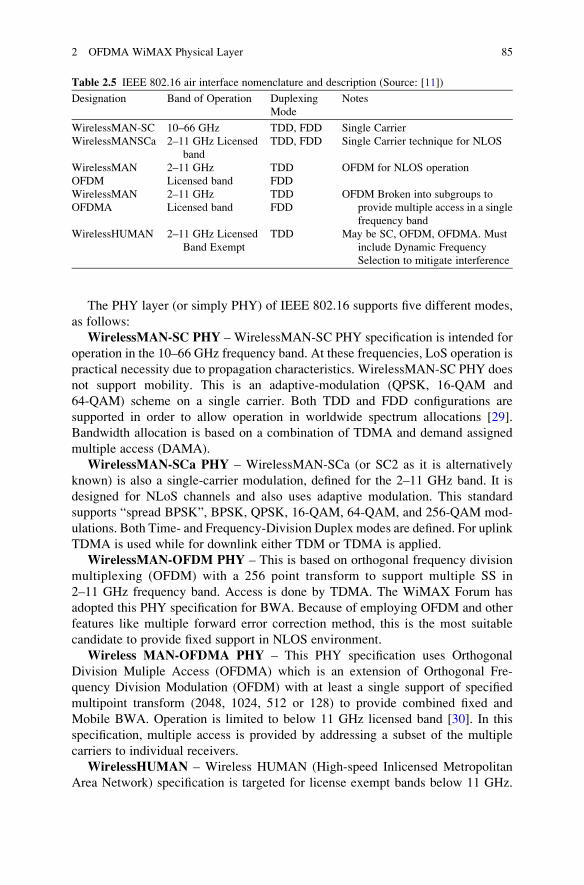
The PHY layer (or simply PHY) of IEEE 802.16 supports five different modes,
as follows:
WirelessMAN-SC PHY – WirelessMAN-SC PHY specification is intended for
operation in the 10–66 GHz frequency band. At these frequencies, LoS operation is
practical necessity due to propagation characteristics. WirelessMAN-SC PHY does
not support mobility. This is an adaptive-modulation (QPSK, 16-QAM and
64-QAM) scheme on a single carrier. Both TDD and FDD configurations are
supported in order to allow operation in worldwide spectrum allocations [29].
Bandwidth allocation is based on a combination of TDMA and demand assigned
multiple access (DAMA).
WirelessMAN-SCa PHY – WirelessMAN-SCa (or SC2 as it is alternatively
known) is also a single-carrier modulation, defined for the 2–11 GHz band. It is
designed for NLoS channels and also uses adaptive modulation. This standard
supports “spread BPSK”, BPSK, QPSK, 16-QAM, 64-QAM, and 256-QAM mod-
ulations. Both Time- and Frequency-Division Duplex modes are defined. For uplink
TDMA is used while for downlink either TDM or TDMA is applied.
WirelessMAN-OFDM PHY – This is based on orthogonal frequency division
multiplexing (OFDM) with a 256 point transform to support multiple SS in
2–11 GHz frequency band. Access is done by TDMA. The WiMAX Forum has
adopted this PHY specification for BWA. Because of employing OFDM and other
features like multiple forward error correction method, this is the most suitable
candidate to provide fixed support in NLOS environment.
Wireless MAN-OFDMA PHY – This PHY specification uses Orthogonal
Division Muliple Access (OFDMA) which is an extension of Orthogonal Fre-
quency Division Modulation (OFDM) with at least a single support of specified
multipoint transform (2048, 1024, 512 or 128) to provide combined fixed and
Mobile BWA. Operation is limited to below 11 GHz licensed band [30]. In this
specification, multiple access is provided by addressing a subset of the multiple
carriers to individual receivers.
WirelessHUMAN – Wireless HUMAN (High-speed Inlicensed Metropolitan
Area Network) specification is targeted for license exempt bands below 11 GHz.
Table 2.5 IEEE 802.16 air interface nomenclature and description (Source: [11])
Designation Band of Operation Duplexing
Mode
Notes
WirelessMAN-SC 10–66 GHz TDD, FDD Single Carrier
WirelessMANSCa 2–11 GHz Licensed
band
TDD, FDD Single Carrier technique for NLOS
WirelessMAN 2–11 GHz TDD OFDM for NLOS operation
OFDM Licensed band FDD
WirelessMAN 2–11 GHz TDD OFDM Broken into subgroups to
provide multiple access in a single
frequency band
OFDMA Licensed band FDD
WirelessHUMAN 2–11 GHz Licensed
Band Exempt
TDD May be SC, OFDM, OFDMA. Must
include Dynamic Frequency
Selection to mitigate interference
2 OFDMA WiMAX Physical Layer 85

For unlicensed frequency bands, in addition to huge spectrum allocation avail-
able for public network access nationwide, any of the air interfaces specified for
2–11 GHz can be used. This specification, however, supports only TDD for
duplexing [1]. Unlicensed bands allow experimentation and innovation, attracting
significant interest for both academia and industry (manufacturers and service
providers). It is, however, subject to various rules and constraints, such as transmit-
ter power (or effective isotropic radiated power) limits.
The details on the above PHY air interface specifications follows:
Payload – Payload refers to individual units of transmission content that are of
interest to some entity at the receiver.
Burst – A burst contains payload data and is formed according to the rules
specified by the burst profile associated with the burst. The existence of the burst is
made known to the receiver through the contents of either the uplink or downlink
maps. For the uplink, a burst is a complete unit of transmission that includes a
leading preamble, encoded payload, and trailing termination sequence.
Burst Set – A burst set is a self-contained transmission entity consisting of a
preamble, one or more concatenated bursts, and a trailing termination sequence. For
the uplink, burst set is synonymous with burst.
Burst Frame – A burst frame contains all information included in a single
transmission. The DL and UL sub-frames each hold a burst frame.
Burst Profiles – Burst profile contains information about various parameters
such as modulation type, FEC, preamble type and guard times. Burst profile is a part
of downlink as well as uplink frame.
MAC Frame – A MAC frame refers to the fixed bandwidth intervals reserved
for data exchange. For TDD, a MAC frame consists of one downlink and one uplink
sub-frame, delimited by the transmit transition gap (TTG). For FDD, the MAC
frame corresponds to the maximum length of the downlink sub-frame. FDD uplink
sub-frames operate concurrently with downlink sub-frames but on a separate
(frequency) channel.
Downlink Channel Descriptor (DCD) – DCD describes the downlink PHY
characteristics of a downlink channel. The DCD is type of medium access control
management message and is broadcasted by the BS at periodic intervals. The DCD
contains information regarding frame duration codes and downlink burst profiles.
Uplink Channel Descriptor (UCD) – UCD describes the downlink PHY
characteristics of a uplink channel.UCD is also a type of medium access control
management message and is broadcasted periodically by the BS.
Downlink Interval Usage Codes (DIUCs) – DIUC is an interval usage code
specific to a downlink. An interval usage code identifies a particular burst profile
that can be used by a downlink or uplink transmission interval. Thus DIUC is used
to identify the burst profile of downlink allocations in DL MAPs.
Uplink Interval Usage Codes (UIUCs) – UIUC is an interval usage code
specific to an uplink.
DownlinkMAP (DLMAP) –DL-MAP is type MACmessage that defines burst
start times for both time division multiplex and time division multiple access
(TDMA) for downlink allocations. These allocations are specified in PHY specific
86 R. Prasad and F.J. Velez

DLMAP elements. The DLMAP also include information about DIUCs to identify
the burst profile. DL_MAP is the only mechanism used in WirelessMAN-SC and
WirelessMANSC-a PHYs to describe DL access while in WirelessMAN-OFDM
and for WirelessMAN-OFDMA an additional format called downlink frame prefix
(DLFP) is also used.
Uplink MAP (UL MAP) – UL MAP describes the UL TDMA allocations in
which exact time offsets, along with the burst profiles with which the SSs will
transmit data is specified. Similar to the DL MAP, UL MAP also include informa-
tion about UIUCs to identify the burst profile. The UL contention slots also form
part of the UL MAP.
2.13 WirelessMAN-SC PHY
2.13.1 Overview
WirelessMAN-SC PHY mode of IEEE 802.16-2004 supports operation in the
10–66 GHz frequency band. This PHY specification is designed with a high degree
of flexibility in order to allow service providers the ability to optimize system
deployments with respect to cell planning, cost, radio capabilities, services and
capacity. Both TDD and FDD configurations are allowed for flexible spectrum
usage. The FDD mode also supports full-duplex SSs as well as half duplex SSs.
Both cases use a burst transmission format, whose framing mechanism supports
adaptive burst profiling in which transmission parameters, including the modulation
and coding schemes, may be adjusted individually to each SS on a frame-by-frame
basis. The FDD case supports full-duplex SSs as well as half duplex SSs, which do
not transmit and receive simultaneously.
The 802.16 supports adaptive burst profiling in which transmission parameters,
including the modulation and coding scheme may be adjusted to each SS on frame
by frame basis. The bandwidth allocation, that is, the allocation for channel time is
based on combination of time division multiple access (TDMA) and demand–
assigned multiple access (DAMA).The uplink channel is divided into a number
of time slots. These time slots are assigned on frame by frame basis by the BS
MAC. The SS uses these time slots for registration, ranging, contention bandwidth
requests and user traffic. The downlink channel is TDM, with the information for
each SS multiplexed onto a single stream of data and received by all SSs within the
same sector. To support half-duplex FDD SSs, provision is also made for a TDMA
portion of the downlink.
The downlink PHY includes a Transmission Convergence sub-layer that inserts
a pointer byte at the beginning of the payload to help the receiver identify the
beginning of a MAC PDU. Data bits coming from the Transmission Convergence
sub-layer are randomized, FEC encoded, and mapped to a QPSK, 16-QAM, or
64-QAM (optional) signal constellation.
2 OFDMA WiMAX Physical Layer 87

The uplink PHY is based upon TDMA burst transmission. Each burst is designed
to carry variable-length MAC PDUs. The transmitter randomizes the incoming
data, FEC encodes it, and maps the coded bits to a QPSK, 16-QAM (optional), or
64-QAM (optional) constellation.
2.13.2 Duplexing Techniques and PHY Type ParameterEncodings
2.13.2.1 FDD Mode and FDD frame
For FDD operation the uplink and downlink channels are on separate frequencies.
The capability of the downlink to be transmitted in bursts facilitates the use
of different modulation types and allows the system to simultaneously support
full-duplex SSs and half-duplex SSs. The downlink carrier may be continuous.
Figure 2.14 shows the basics of the FDD operation.
Figure 2.15 presents the half duplex FDD frame while Fig. 2.16 shows the full
duplex one.
2.13.2.2 TDD Mode and TDD frame
In the TDD operation, the uplink and downlink transmissions share the same
frequency band but are separated in time. A TDD frame has a fixed duration
and contains one downlink and one uplink sub-frame. The TDD framing is adap-
tive, that is, the link capacity allocated to the downlink versus uplink may vary.
Figure 2.17 shows the TDD frame structure.
Using TDD enables efficient support of asymmetric traffic for easy support
of IP-based traffic, channel reciprocity and advanced antenna systems. Hybrid-
automatic repeat request (H-ARQ) provides added robustness with rapidly
Broadcast
Full Duplex Capable SS
Half Duplex SS # 1
Half Duplex SS # 2
frame
time
Uplink
Downlink f1
f2
Fig. 2.14 FDD frame structure
88 R. Prasad and F.J. Velez

Full Duplex Capable SS
frame
time
Uplink
Downlink f1
f2
Fig. 2.16 Full Duplex framing
Half Duplex SS # 1
Half Duplex SS # 2
frame
time
Uplink
Downlink f1
f2
Fig. 2.15 H-FDD framing
Frame j – 2 Frame j – 1 Frame j Frame j + 1 Frame j + 2
Adaptive
Downlink Subframe Uplink Subframe
n = (Symbol Rate x Frame Duration) / 4
PS 0 PS n – 1
Fig. 2.17 TDD frame structure
2 OFDMA WiMAX Physical Layer 89

changing radio path conditions in high mobility scenarios. TDD is less complex
than FDD, where uplink and downlink traffic are separated by a guard time.
2.13.3 Frame Structure
The WirelessMAN-SC PHY operates in a framed format. Within each frame are a
downlink sub-frame and an uplink sub-frame. The downlink sub-frame begins with
information necessary for frame synchronization and control. In the TDD, the
downlink sub-frame comes first, followed by the uplink sub-frame. The DL sub-
frame begins with the information necessary for frame synchronisation and control
as shown in Fig. 2.18. The downlink frame starts with a frame start preamble used
by the PHY for synchronisation and equalization. This is followed by frame control
section which is indicated in form of maps. Control section is followed by the TDM
data section which is organized in the form of bursts. These burst profiles are
organized in decreasing robustness fashion. The burst begins with the QPSK
modulation followed by 16QAM and 64QAM. In the FDD case, uplink transmis-
sions occur concurrently with the downlink frame. Supported frame durations
allows for three frame durations 0.5, 1, and 2 ms.
Downlink Subframe
Downlink Subframe
Uplink Subframe (TDMA)
Uplink Subframe TDMA
FDD
TDD
Frequency
Time
Preamble MapsQPSKBurst
Control info Data
16-QAMBurst
64-QAMBurst
Fig. 2.18 Frame structure
90 R. Prasad and F.J. Velez

2.13.4 Downlink PHY
In a TDD transmission, the BS basically transmits a TDM signal. This TDM signal
is a series of individual subscriber stations allocated time slots. The downlink sub-
frame starts with a preamble, which is used for synchronization and equalisation.
The frame start preamble is a 32-symbol sequence generated by repeating a
16-symbol sequence. The frame control section is used to pass control information
for the channel to all SSs, and this data is not encrypted.
The following section is a broadcasting control section that contains the DL-
MAP and UL-MAP, which specified when physical layer transmissions (modula-
tion and FEC changes) occur within the downlink frame as well as the UL-MAP.
The TDM portions are just payloads to be transmitted to SSs which are organized
into bursts with different burst profiles and therefore different level of transmission
robustness. The bursts are always transmitted in order of decreasing robustness.
The DL-MAP portion of the frame control section provides listening SSs with
the characteristics of the downlink channel. This information includes: PHY syn-
chronization (i.e., schedule of physical layer transitions to include modulation and
FEC changes), a downlink channel descriptor message (DCD), a programmable
48-bit BS identifier, and the number of data elements to follow. Reference [21] The
DCD and the BS identifier identify the channel and the BS, respectively, and thus
together are useful for situations where a SS is on the border of multiple IEEE
802.16 sectors or cells.
For example, with the use of a single FEC type with fixed parameters, data
begins with QPSK modulation, followed by 16-QAM, followed by 64-QAM. In the
case of TDD, a TTG separates the downlink sub-frame from the uplink sub-frame.
The frames in TDMA portions may differ in bandwidth due to the dynamics of
bandwidth demand for the variety of services that maybe active. Since the recipient
SS is implicitly indicated in the MAC headers rather than in the DL-MAP, SSs
listen to all portions of the downlink sub-frame they are capable of receiving. The
structure of the downlink sub-frame using TDD is illustrated in Fig. 2.19.
The UL-MAP is used to communicate uplink channel access allocations to the
SSs. Information provided in the UL-MAP include: Uplink channel identifier,
uplink channel descriptor (UCD), number if information elements to map, alloca-
tion start time and map information elements. The UCD is used to provide SSs with
information regarding the required uplink burst profile. The map information
elements message identifies the SS this information applies to by using a connection
identifier (CID). This message also provides an uplink interval usage code (UIUC)
and offsets that are to be used by the SS to transmit on the uplink. The uplink
interval usage code is used to specify the burst profile to be used by the SS on the
uplink.
The transmit transition gap (TTG) is a gap between the downlink burst and the
subsequent uplink burst. This gap allows time for the BS to switch from the
transmitter to the receive mode while SSs switch from receive to transmit mode.
During this gap, the BS and SS are not transmitting modulated data but simply
2 OFDMA WiMAX Physical Layer 91

allowing the BS transmitter carrier to ramp down, the transmit/receive (Tx/Rx)
antenna switch to “actuate”, and the BS receiver section to “activate”. After the gap,
the BS receiver shall look for the first symbols of uplink burst. This gap is an integer
number of PS durations and starts on a PS boundary.
The receive transition gap (RTG) is a gap between the uplink burst and the
subsequent downlink burst. This gap allows time, for the BS, to switch from receive
to transmit mode and SSs to switch from transmit to receive mode. During this gap,
the BS and SS are not transmitting modulated data but simply allowing the BS
transmitter carrier to ramp up, the Tx/Rx antenna switch to “actuate”, and the SS
receiver sections to “activate”. After the gap, the SS receivers shall look for the first
symbols of QPSK modulated data in the downlink burst. This gap is an integer
number of PS durations and starts on a PS boundary.
For FDD case, the structure of the downlink sub-frame is illustrated in Fig. 2.20.
As in the TDD case, the downlink sub-frame begins with a Frame Start Preamble
followed by a frame control section and a TDM portion organized into bursts
transmitted in decreasing order of burst profile robustness. This TDM portion of
the downlink sub-frame contains data transmitted to one or more of the following:
l Full-duplex SSsl Half-duplex SSs scheduled to transmit later in the frame than they receivel Half-duplex SSs not scheduled to transmit in this frame
The FDD downlink sub-frame continues with a TDMA portion used to transmit
data to any half-duplex SSs scheduled to transmit earlier in the frame than they
receive. This allows an individual SS to decode a specific portion of the down-
link without the need to decode the entire downlink sub-frame. In the TDMA
portion, each burst begins with the Downlink TDMA Burst Preamble for phase
BroadcastControlDIUC = 0
TDMDIUC a
TDMDIUC b
TDMDIUC c
TDM Portion
Pre
ambl
e
DL-MAP UL-MAP
Pre
ambl
e
TTG
Fig. 2.19 TDD downlink sub-frame
92 R. Prasad and F.J. Velez

resynchronization. Bursts in TDMA portion need not be ordered by burst profile
robustness. The FDD frame control section includes a map of both the TDM and
TDMA bursts.
The TDD downlink sub-frame, which inherently contains data transmitted to
SSs, transmit later in the frame than they receive, and is identical in structure to the
FDD downlink sub-frame for a frame in which no half duplex SSs are scheduled to
transmit before they receive.
2.13.4.1 Downlink Channel Encodings
The downlink data sections are used for transmitting data and control messages to
the specific SSs. The data are always FEC coded and are transmitted at the current
operating modulation of the individual SS. In the TDM portion, data is transmitted
in order of decreasing burst profile robustness.
For TDMA portion, the data are grouped into separately delineated bursts that
need not be in robustness order. The DL-MAP message contains a map stating at
which PS the burst profile changes occur.
The number of PSs allocated to a particular burst is calculated from the DL-
MAP, which indicates the starting position of each burst as well as the burst
profiles. If n denote the minimum number of PSs required for one FEC codeword
of the given burst profile (where n is not necessarily an integer), then, i = kn + j + q,where k is the number of whole FEC code words that fit in the burst, j (notnecessarily an integer) is the number of PSs occupied by the largest possible
shortened codeword, and q (0 � q < 1) is the number of PSs occupied by pad
bits inserted at the end of the burst to guarantee that i is an integer.
BroadcastControlDIUC = 0
TDMDIUC a
TDMDIUC b
TDMDIUC c
TDM Portion
Pre
ambl
e
DL-MAP UL-MAP
Pre
ambl
e
TDMADIUC d
Pre
ambl
e
TDMADIUC e
Pre
ambl
e
TDMADIUC f
Pre
ambl
e
Pre
ambl
e
TDMA Portion
Burst Start Points
Fig. 2.20 FDD downlink sub-frame structure
2 OFDMA WiMAX Physical Layer 93

In Fixed Codeword Operation, j is always 0. A codeword can end partway
through a modulation symbol as well as partway through a PS. When this occurs,
the next codeword shall start immediately, with no pad bits inserted. At the end of
the burst (i.e., when there is no next codeword), then 4q symbols are added as
padding (if required) to complete the PS allocated in the DL-MAP. The number of
padding bits in these padding symbols is 4q times the modulation density, where the
modulation density is two for QPSK, four for 16-QAM, and six for 64-QAM. Note
that padding bits may be required with or without shortening. Either k or j, but notboth, may be zero. The number j implies some number of bits b. Assuming that j isnonzero, it shall be large enough such that b is larger than the number of FEC bits, r,added by the FEC scheme for the burst. The number of bits preferably an integral
number of bytes) available for user data in the shortened FEC codeword is b–r. Anybits that may be left over from a fractional byte are encoded as binary 1 to ensure
compatibility with the choice of 0xFF for pad. A codeword cannot have less than
six information bytes. This is illustrated in Fig. 2.21.
In the case of TDMA downlink, a burst includes the Downlink TDMA Burst
Preamble of length p PSs, and the DL-MAP entry points to its beginning, Fig. 2.22.
2.13.4.2 Downlink Transmission Convergence Sub-layer
The downlink payload is segmented into blocks of data designed to fit into the proper
codeword size after the CS pointer byte is added. The payload length may vary,
n n n q
FECCodeword
FECCodeword
FECCodeword
FECCodeword
j
Number of modulation symbols = 4i
Number of PSs I = y – x = kn + j + q
Map entry mstarts on PS = x
b-r data bits r redundancy bits Map entry m +1starts on PS = y
j PSs = b bits
Fig. 2.21 DL-MAP usage with shortened FEC blocks –TDM case
94 R. Prasad and F.J. Velez

depending onwhether shortening of codewords is allowed or not for this burst profile.
A pointer byte shall be added to each payload segment, as illustrated in Fig. 2.23.
The pointer field identifies the byte number in the packet. It indicates either the
beginning of the first MAC PDU starts in the packet or the beginning of any stuff
bytes that precede the next MAC PDU. For reference, the first byte in the packet is
referred to as byte number 1. If no MAC PDU or stuff bytes begin in the CS packet
then the pointer byte is set to 0. When no data is available to transmit, a stuff_byte
pattern having a value (0xFF) shall be used within the payload, to fill any gaps
between the IEEE 802.16 MAC PDUs. This value is chosen as an unused value for
the first byte of the IEEE 802.16 MAC PDU, which is designed to never have this
value (Fig. 2.23).
The downlink PHY coding and modulation for this mode is summarized in the
block diagram from Fig. 2.24.
The downlink channel supports adaptive burst profiling on the user data portion
of the frame. Up to twelve burst profiles can be defined. Since there are optional
MAC PDU that hasstarted in the previous packet
Transmission Convergence Sublayer (TC) PDU
First MAC PDU thatstarts in this TC packet
Second MAC PDU thatstarts in the TC packet
P
P = 1 byte pointer field
Fig. 2.23 Format of the downlink convergence sub-layer PDU
p n n q
FECCodeword
FECCodeword
FECCodeword
ShortenedFEC
Codeword
j
Number of modulation symbols = 4i
Number of PSs I = y – x = p + kn + j + q
Map entry mstarts on PS = x
b-r data bits r redundancy bits Map entry m + 1starts on PS = y
j PSs = b bits
Remainder q(fraction of a PS)4q paddingsymbols
Fig. 2.22 DL-MAP usage with shortened FEC blocks –TDMA case
2 OFDMA WiMAX Physical Layer 95

modulation and FEC schemes that can be implemented at the SS, a method for
identifying the capability of the BS is required. Randomization is employed to
minimize the possibility of transmission of an unmodulated carrier while ensuring
adequate numbers of bit transitions to support clock recovery. The stream of
downlink packets is randomized by modulo-2 addition of the data with the output
of the Pseudo-Random Binary Sequence (PRBS) generator. Selected FEC Code
types are presented in Table 2.6.
2.13.4.3 Downlink Modulation
The PHY uses a multilevel modulation scheme to maximize the utilization of the
air-link. The modulation constellation can be selected per subscriber based on the
quality of the RF channel. In the downlink, the BS supports QPSK and 16-QAM
modulation and, optionally, 64-QAM. In changing from one burst profile to
another, the BS uses one of two power adjustment rules: maintaining constant
constellation peak power (power adjustment rule ¼ 0), or maintaining constant
constellation mean power (power adjustment rule ¼ 1). In the former case, corner
RandomizationFEC
EncoderPreamblePrepend
SymbolMapper
BasebandPulse
Shaping
ModulatorAnd
PhysicalInterface
PhysicalInterface
andBurst Demod
MatchedFilterand
Equalizer
SymbolDemapper
FECDecoder
De-Randomization
Data
Base Station
From RFChannel Data
To RFChannel
SS
Fig. 2.24 Conceptual diagram of the downlink PHY sub-layer
Table 2.6 Selectable FEC code types (From [19])
Code types Outer code Inner code
1 Reed-Solomon over Galois field (GF) (256) None
2 Reed-Solomon over GF (256) (24,16) Block convolutional code
3 (Optional) Reed-Solomon over GF (256) (9,8) Parity check code
4 (Optional) BTC –
96 R. Prasad and F.J. Velez

points are transmitted at equal power levels regardless of modulation type, while in
the latter the signal is transmitted at equal mean power levels regardless of
modulation type. I and Q signals are filtered by square-root raised cosine filters
prior to modulation. The excess bandwidth factor is a ¼ 0.25.
2.13.5 Uplink PHY
2.13.5.1 Uplink Sub-frame
The uplink Transmission Convergence sub-layer operation is identical to that of
downlink. The structure of the uplink sub-frame used by the SS to transmit to the
BS is shown in Fig. 2.25.
During the uplink sub-frame, three types of bursts may be transmitted by the SS
depending upon the need aroused:
l Bursts that are transmitted in contention opportunities reserved for Initial
Rangingl Bursts that are transmitted in contention opportunities defined by Request Inter-
vals reserved for response to multicast and broadcast pollsl Bursts that are transmitted in intervals defined by Data Grant IEs specifically
allocated to individual SSs
Any of these bursts may be present in any uplink sub-frame and may occur in
any order and quantity .The scheduler at BS indicates which bursts are present via
the UL MAP message.
InitialRanging
Opportunities(UIUC = 2)
RequestContention
Opps(UIUC = 1)
SS 1Scheduled
Data(UIUC = i )
...SS N
ScheduledData
(UIUC = j )
SSTGTTG
(TDD)
AccessBurst
Collision AccessBurst CollisionBandwidth
RequestBandwidthRequest
Fig. 2.25 Uplink sub-frame structure (From [19])
2 OFDMA WiMAX Physical Layer 97

The bursts are separated by subscriber station transition gap (SSTGs), which
separates transmission of the various SSs during the uplink sub-frame followed by a
preamble allowing the BS to synchronize to the new SS.
Each uplink burst begins with an uplink preamble. This preamble is based upon a
repetition of a + 45� rotated Constant Amplitude Zero Auto-Correlation (CAZAC)
sequence. Each Uplink Burst Profile in the Uplink Channel Descriptor (UCD)
message includes the following parameters:
l Modulation typel FEC Code Typel Last codeword lengthl Preamble Lengthl Randomizer Seed
2.13.5.2 Uplink PHY Sub-layer
The uplink PHY coding and modulation are summarized in the block diagram
shown in Fig. 2.26.
The uplink modulator implements a randomized, variable modulation which is
set by the BS. QPSK is supported, while 16-QAM and 64-QAM are optional. In
changing from one burst profile to another, the SS uses one of two power adjust-
ment rules: maintaining constant constellation peak power (power adjustment rule
¼ 0), or maintaining constant constellation mean power (power adjustment rule¼ 1).
In the former case, corner points are transmitted at equal power levels regardless of
modulation type, while, in the latter, the signal is transmitted at equal mean power
levels regardless of modulation type.
RandomizationFEC
EncoderPreamblePrepend
SymbolMapper
BasebandPulse
Shaping
ModulatorAnd
PhysicalInterface
PhysicalInterface
andBurst Demod
MatchedFilter
SymbolDemapper
FECDecoder
De-Randomization
Data
SS
From RFChannel Data
To RFChannel
BS
Fig. 2.26 Conceptual block diagram of the uplink PHY (From [19])
98 R. Prasad and F.J. Velez

2.13.5.3 Channel Quality Measurements
Receive Signal Strength Indicator (RSSI) and Carrier-to-interference-plus-noise
ratio (CINR) signal quality measurements and associated statistics can aid in such
processes as BS selection/assignment and burst adaptive profile selection. As
channel behaviour is time-variant, both mean and standard deviation are defined.
The process by which RSSI measurements are taken does not necessarily require
receiver demodulation lock; for this reason, RSSI measurements offer reasonably
reliable channel strength assessments even at low signal levels. On the other hand,
although CINR measurements require receiver lock, they provide information on
the actual operating condition of the receiver, including interference and noise
levels, and signal strength. When collection of RSSI measurements is mandated
by the BS, an SS obtains an RSSI measurement from the downlink burst preambles.
From a succession of RSSI measurements, the SS derives and updates estimates of
the mean and the standard deviation of the RSSI. In the case of CINR, SS obtains
CINR measurements.
2.14 WirelessMAN-OFDM PHY
TheWirelessMAN-OFDM PHY is based on Orthogonal Frequency Division Multi-
plexing (OFDM) modulation and is designed for NLOS operation in the frequency
bands below 11 GHz. It uses 256- point transform and access is by TDMA. This air
interface is mandatory for license exempt bands.
2.14.1 Channel Coding
2.14.1.1 Types and Steps
Channel Coding is an important part of the communication system as it increases
both the capacity and the coverage. In order to meet the BER requirements under
moderate C/N conditions, channel coding is mandatory. There are two main types
of coding schemes: block coding and convolutional coding. Block coding operates
on finite length blocks and convolutional code works often in a continuous manner.
A combination of these is proposed for the down link. Reed-Solomon forward error
code is proposed as the outer code owing to its excellent distance properties and
moderate implementation complexity. In the downlink, the inner code is inherent in
the TCM modulation. There is no overhead in using TCM as it preserves the signal
bandwidth. RS-code is optimal for correcting burst errors that might come from the
TCM demodulator.
The uplink uses robust modulation and needs just a Reed-Solomon block
code.
2 OFDMA WiMAX Physical Layer 99

Channel coding involves three steps:
l Randomizationl Forward Error Correction (FEC)l Interleaving
They are applied in this order at transmission. The inverse operations then
performed, in the reverse order, at the receiver side (Fig. 2.27).
2.14.1.2 Randomization
Data randomization is performed independently on each burst for downlink and
uplink data. Randomization is done to avoid long sequences of consecutive “ones”
or consecutives “zeros”. If the amount of data to transmit does not fit exactly the
amount of data allocated, padding of 0xFF (“1” only) is added to the end of the
transmission block, for the unused integer bytes. The pseudorandom Binary
Sequence (PBRS) generator used for randomisation is shown in Fig. 2.28. Except
the preambles, each and every data byte to be transmitted enters sequentially into
the randomiser, with the Most Significant Byte (MBS) first. Randomisation is not
performed on preambles. Randomiser sequence is applied only to information bits.
The bits issued from the randomizer are then applied to the encoder. The
randomizer is re-initialized on the downlink, at the start of each frame with the
Regular Channel Coding Process
Randomizer FEC Bit-Interleaver Modulation
Data to betransmitted on theSubChannel
Symbols to mapon theSubchannel
Fig. 2.27 OFDM PHY transmission chain
151413121110987654321
LSB MSB
data indata out
Fig. 2.28 PBRS generator used for the data randomization in OFDM and OFDMA PHY
(From [19])
100 R. Prasad and F.J. Velez

sequence: 1 0 0 1 0 1 0 1 0 0 0 0 0 0 0. The randomizer is not reset at the start of burst
#1, but rather at start of subsequent bursts. The frame number used for initialization
refers to the frame in which the downlink burst is transmitted.
2.14.1.3 FEC
FEC introduces redundancy in the data before it is transmitted. The redundant data
(check symbols) are transmitted with the original data to the receiver. There are
three methods of channel coding specified by OFDM PHY:
l Reed Solomon concatenated with convolutional coding(RS-CC)l Block turbo codes(BTCs)l Convolutional turbo codes(CTCs)
An FEC, consisting of the concatenation of a Reed-Solomon outer code and a
rate-compatible convolutional inner code, is supported on both uplink and down-
link. RS-CC is mandatory, whereas BTC and CTC are optional. More complex
design issues are faced for BTC and CTC, although they are able to provide 2–3 dB
higher gain.
2.14.2 Concatenated Reed–Solomon-ConvolutionalCode (RS-CC)
The Reed–Solomon encoding is derived from a systematic RS (N ¼ 255, K ¼ 239,
T ¼ 8) code using GF(28), where N is the number of overall bytes after encoding,
K is the number of data bytes before encoding and T is the number of data bytes
which can be corrected. This code is then shortened and punctured to enable
variable block sizes and variable error-correction capability. The code after this is
reduced to K’ data bytes. Then, add 239-K’ zero bytes as a prefix. After encoding
discard these 239-K’ zero bytes. When a codeword is punctured to permit T’ bytesto be corrected, only the first 2T’ of the total 16 parity bytes is employed.
Each RS block is encoded by the binary convolutional encoder, having a native
rate of 1/2, and constraint length equal to 7. The encoding is performed by first
passing the data in block format through the RS encoder and then passing it through
a convolutional encoder. A single 0x00 tail byte is appended to the end of each
burst. This tail byte is done after randomization. In the RS encoder, the redundant
bits are sent before the input bits, keeping the 0x00 tail byte at the end of the
allocation. When the total number of data bits in a burst is not an integer number of
bytes, zero pad bits are added after the zero tail bits. The zero pad bits are not
randomized.
Note that this situation can occur only in subchannelization. In this case, the RS
encoding is not employed. Table 2.7 presents the block sizes and the code rates used
2 OFDMA WiMAX Physical Layer 101

for the different modulations and code rates. With 64-QAM (optional for license-
exempt bands) the code is implemented if the modulation is implemented. In the
case of BPSK modulation, the RS encoder is bypassed (Fig. 2.29).
2.14.2.1 Block Turbo Codes (BTCs)
Block Turbo Codes (BTC) are defined as an optional FEC for OFDM and OFDMA
PHY. The BTC is also optional in WiMAX profiles.
In IEEE 802.16, both for OFDM and OFDMA PHY, the BTC is based on the
product of two simple component codes, which are binary extended Hamming
codes or parity check codes. It should be also noted that the codes are not the same
for the two PHYs. Data bit ordering for the composite BTC matrix is defined such
that the first bit in the first row is the LSB (Least Significant Byte) and the last data
bit in the last data row is the MSB.
Table 2.7 Mandatory channel coding per modulation
Modulation Uncoded block size
(bytes)
Coded block size
(bytes)
Overall coding
rate
RS code CC code
rate
BPSK 12 24 1/2 (12,12,0) 1/2
QPSK 24 48 1/2 (32,24,4) 2/3
QPSK 36 48 3/4 (40,36,2) 5/6
16-QAM 48 96 1/2 (64,48,8) 2/3
16-QAM 72 96 3/4 (80,72,4) 5/6
64-QAM 96 144 2/3 (108,96,6) 3/4
64-QAM 108 144 3/4 (120,108,6) 5/6
2
Data burst
1
Tail Byte
RS Parity Bits
CC Encoder
Fig. 2.29 RS-CC encoding process
102 R. Prasad and F.J. Velez
2.14.2.2 Interleaving
Interleaving is a technique where sequential data words or packets are spread across
several transmitted data bursts. It is used to protect the transmission against long
sequences of consecutive errors, which are very difficult to correct. These long
sequences of error may affect a lot of bits in a row and can then cause many
transmitted burst losses. All encoded data bits are interleaved by a block interleaver
with a block size corresponding to the number of coded bits per the allocated
subchannels per OFDM symbol, Ncbps. The interleaver is defined by a two step
permutation. The first ensures that adjacent coded bits are mapped onto nonadjacent
subcarriers. The second permutation insures that adjacent coded bits are mapped
alternately onto less or more significant bits of the constellation, thus avoiding long
runs of lowly reliable bits.
After bit interleaving, the data bits are entered serially to the constellation
mapper. BPSK, Gray-mapped QPSK, 16-QAM, and 64-QAM are supported,
whereas the support of 64-QAM is optional for license-exempt bands. Pilot sub-
carriers are inserted into each data burst in order to constitute the Symbol and they
are modulated according to their carrier location within the OFDM symbol.
2.14.2.3 Modulation
After bit interleaving, the data bits are entered serially to the constellation mapper.
The OFDM PHY mandates BPSK as well as Gray-mapped QPSK, 16-QAM, and
64-QAM as shown in Figure 2.30. The 64-QAM constellation is optional for
license-exempt bands. This is to allow use of IEEE 802.11 RF components as
they do meet the 64-QAM performance requirements of IEEE 802.16 standard [29].
2.14.2.4 Pilot Modulation
Pilot subcarriers are modulated with a BPSK signal. The values to be used are
derived by passing fixed initialization sequences through a PRBS generator with
polynomial X11 + X9 + 1 clocked with the OFDM symbol rate. This is done UL as
well as Dl separately. The value of the individual pilots in a single OFDM symbol
are then defined as being either equal or the negative of the BPSK–modulated
PRBS output.
2.14.2.5 Frame Structure
The OFDM PHY supports two different types of Frame Structures based on its two
architectures, it supports, PMP and Mesh. The frame structure for PMP is manda-
tory but for mesh based architectures is optional. The frame durations for both
architectures are between 2.5 and 20 ms.
2 OFDMA WiMAX Physical Layer 103
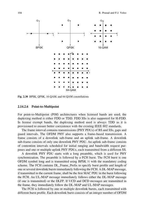
2.14.2.6 Point-to-Multipoint
For point-to-Multipoint (PtM) architectures when licensed bands are used, the
duplexing method is either FDD or TDD. FDD SSs is also supported for H-FDD.
In license exempt bands, the duplexing method used is always TDD as it is
provisioned to ensure better coexistence with the existing IEEE 802 standards.
The frame interval contains transmissions (PHY PDUs) of BS and SSs, gaps and
guard intervals. The OFDM PHY also supports a frame-based transmission. A
frame consists of a downlink sub-frame and an uplink sub-frame. A downlink
sub-frame consists of only one downlink PHY PDU. An uplink sub-frame consists
of contention intervals scheduled for initial ranging and bandwidth request pur-
poses and one or multiple uplink PHY PDUs, each transmitted from a different SS.
A downlink PHY PDU starts with a long preamble, which is used for PHY
synchronization. The preamble is followed by a FCH burst. The FCH burst is one
OFDM symbol long and is transmitted using BPSK ½ with the mandatory coding
scheme. The FCH contains DL_Frame_Prefix to specify burst profile and length of
one or several downlink bursts immediately following the FCH. ADL-MAPmessage,
if transmitted in the current frame, shall be the first MAC PDU in the burst following
the FCH. An UL-MAP message immediately follows either the DL-MAP message
(if one is transmitted) or the DLFP. If UCD and DCD messages are transmitted in
the frame, they immediately follow the DL-MAP and UL-MAP messages.
The FCH is followed by one or multiple downlink bursts, each transmitted with
different burst profile. Each downlink burst consists of an integer number of OFDM
Q
I
Q
I
Q
I
Q
I
BPSK QPSK 16-QAM
64-QAM
Fig. 2.30 BPSK, QPSK, 16-QAM, and 64 QAM constellations
104 R. Prasad and F.J. Velez

symbols. Location and profile of the first downlink burst is specified in the Down-
link Frame Prefix (DLFP). The location and profile of the maximum possible
number of subsequent bursts shall also be specified in the DLFP. At least one full
DL-MAPmust be broadcast in burst #1 within the Lost DL-MAP Interval. Location
and profile of other bursts are specified in DL-MAP. Profile is specified either by a
4-bit Rate_ID (for the first DL burst) or by DIUC. The DIUC encoding is defined in
the DCD messages. HCS field occupies the last byte of DLFP. If there are unused
IEs in DLFP, the first unused IE must have all fields encoded as zeros.
The DL Sub-frame may optionally contain an STC zone in which all DL bursts
are STC encoded. If an STC zone is present, the last used IE in the DLFP shall have
DIUC = 0 and the IE shall contain information on the start time of the STC zone.
The STC zone ends at the end of the frame. The STC zone starts from a preamble
and an STC encoded FCH-STC burst, which is one symbol with the same payload
format. The FCH-STC burst is transmitted at BPSK rate ½. It is followed by one or
several STC encoded PHY bursts. The first burst in the STC zone may contain a
DLMAP applicable only to the STC zone. If DL-MAP is present, it shall be the first
MAC PDU in the payload of the burst.
With the OFDM PHY, a PHY burst, either a downlink PHY burst or an uplink
PHY burst, consists of an integer number of OFDM symbols, carrying MAC
messages, that is, MAC PDUs. To form an integer number of OFDM symbols,
unused bytes in the burst payload may be padded by the bytes 0xFF. Then the
payload should be randomized, encoded, and modulated using the burst PHY
parameters specified by this standard. If an SS does not have any data to be
transmitted in an UL allocation, the SS shall transmit an UL PHY burst containing
a bandwidth request header, with BR = 0 and its basic CID. If the allocation is large
enough, an AAS enabled SS may also provide an AAS Feedback Response (AAS-
FBCK-RSP) message. An SS transmits during the entirety of all of its UL alloca-
tions, using the standard padding mechanism to fill allocations if necessary
(Fig. 2.31).
In each TDD frame, the TTG and RTG is inserted between the downlink and
uplink sub-frame and at the end of each frame, respectively, to allow the BS to turn
around. In TDD and H-FDD systems, subscriber station allowances must be made
by a transmit-receive turnaround gap SSTTG and by a receive-transmit turnaround
gap SSRTG. The BS shall not transmit downlink information to a station later than
(SSRTG+RTD) before its scheduled uplink allocation, and shall not transmit
downlink information to it earlier than (SSTTG-RTD) after the end of scheduled
uplink allocation, where RTD denotes Round-Trip Delay. The parameters SSRTG
and SSTTG are capabilities provided by the SS to BS upon request during network
entry (Fig. 2.32).
2.14.2.7 Mesh
The PMP topology supports both TDD and FDD duplexing modes, but for Mesh
only TDD mode is supported. For Mesh mode there is no separate downlink and
2 OFDMA WiMAX Physical Layer 105

uplink sub-frames as all the stations have the same hierarchy. In addition to the
PMP frame structure IEEE 802.16 defines, an optional frame structure to facilitate
Mesh networks. The contents of the mesh frame are described below (Fig. 2.33).
A Mesh frame consists of a control and data sub-frame. The control sub-frame
serves two basic functions. One is the creation and maintenance of cohesion
between the different systems, termed “network control”. The other is the coordi-
nated scheduling of data-transfers between systems, termed “schedule control”
frames with a network control sub-frame occur periodically, as indicated in the
Network Descriptor. All other frames have a schedule control sub-frame. The
length of the control sub-frame is fixed and of length OFDM symbols, with
indicated in the Network Descriptor.
2.14.2.8 Network Control Sub-frame
During a network control sub-frame, the first seven symbols are allocated for
network entry, followed by sets of seven symbols for network configuration. During
a schedule control sub-frame, the Network Descriptor indicates how many (MSH-
DSCH-NUM) Distributed Scheduling messages may occur in the control
sub-frame. The first symbols are allocated to transmission bursts containing
Frame n – 1 Frame n Frame n + 1 Frame n + 2
DL PHY PDUContention slot for
Initial rangingContention slot for
IBW requestsUL PHY PDU from
SS#1UL PHY PDU from
SS#k
Preamble FCH DL burst#1 DL Burst#2 DL Burst#n Preamble UL burst
DLFPBroadcastmessages
RegularMAC PDUs
MAC Msg 1MAC PDU –1
MAC Msg NMAC PDU–n Pad
MAC Msg 1MAC PDU – 1
MAC Msg NMAC PDU–n Pad
MAC Header6 bytes
MAC msgpayload(optional)
CRC(optional)MAC Header
6 bytesMAC msg
payload(optional)CRC(optional)
time
DL subframe UL subframe
One or multiple DL bursts,each with differentmodulation/coding
transmitted inorder ofdecreasing robustness
One OFDM sybmol withwell-known modulation/coding(BPSK rate ½) asdefined in Table 2.15
E.g: DL-MAP, UL-MAP,DCD, UCD
One UL burstper UL PHYPDU transmitted in the
modulation/coding specificto the source SS
Fig. 2.31 Example of the OFDM structure with TDD (adapted from [19])
106 R. Prasad and F.J. Velez
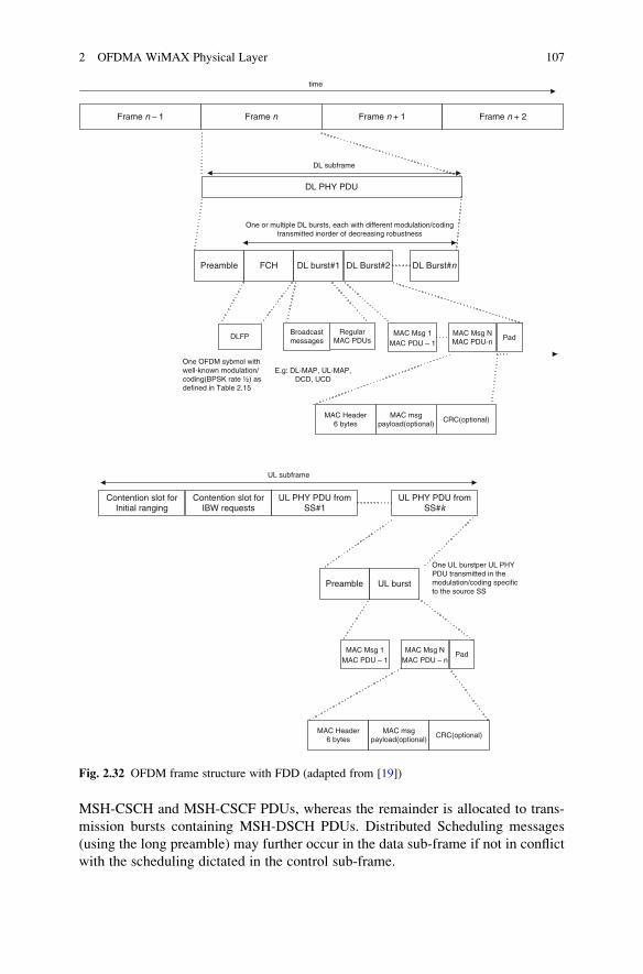
MSH-CSCH and MSH-CSCF PDUs, whereas the remainder is allocated to trans-
mission bursts containing MSH-DSCH PDUs. Distributed Scheduling messages
(using the long preamble) may further occur in the data sub-frame if not in conflict
with the scheduling dictated in the control sub-frame.
Frame n – 1 Frame n Frame n + 1 Frame n + 2
DL PHY PDU
Preamble FCH DL burst#1 DL Burst#2 DL Burst#n
DLFPBroadcastmessages
RegularMAC PDUs
MAC Msg 1MAC PDU – 1
MAC Msg NMAC PDU-n
Pad
MAC Header6 bytes
MAC msgpayload(optional)
CRC(optional)
time
DL subframe
UL subframe
One or multiple DL bursts, each with different modulation/codingtransmitted inorder of decreasing robustness
One OFDM sybmol withwell-known modulation/coding(BPSK rate ½) asdefined in Table 2.15
E.g: DL-MAP, UL-MAP,DCD, UCD
Contention slot forInitial ranging
Contention slot forIBW requests
UL PHY PDU fromSS#1
UL PHY PDU fromSS#k
Preamble UL burst
MAC Msg 1MAC PDU – 1
MAC Msg NMAC PDU – n
Pad
MAC Header6 bytes
MAC msgpayload(optional)
CRC(optional)
One UL burstper UL PHYPDU transmitted in themodulation/coding specificto the source SS
Fig. 2.32 OFDM frame structure with FDD (adapted from [19])
2 OFDMA WiMAX Physical Layer 107

All transmissions in the control sub-frame are sent by using QPSK-1/2 with the
mandatory coding scheme. The data sub-frame is divided into minislots, which are,
with possible exception of the last minislot in the frame, of size ceiling [(OFDM
symbols per frame – MSH-CTRL-LEN � 7)/256]. A scheduled allocation consists
of one or more minislots.
2.14.2.9 Control Mechanism: Synchronization
For TDD and FDD realizations, it is recommended (but not required) that all
BSs be time synchronized to a common timing signal. In the event of the loss
Frame n – 1 Frame n Frame n + 1 Frame n + 2
Networkentry
Networkconfig
Networkcoconfig
time
Network Control subframe
PHY trburs from
SS#j
PHY trburst from
SS#k
Data subframe
CentralSched
CentralConf
DistSched
PHY tr bursfrom SS#j
PHY tr burstfrom SS#k
Data subframe
Networkentry
Long preamble MAC PDU w/MSH-NENT
GaurdSymbol
GaurdSymbol
GaurdSymbol
CentralConf
Long preamble MAC PDU w/MSH-CSCF
GaurdSymbol
Networkconfig
Long preamble MAC PDU w/MSH-NCFG
GaurdSymbol
CentralSched
Long preamble MAC PDU w/MSH-CSCH
GaurdSymbol
Dist Sched
Long preambleMAC PDU w/MSH-DSCH
GaurdSymbol
Schedule Control subframe
Fig. 2.33 Mesh frame structure (adapted from [19])
108 R. Prasad and F.J. Velez

of the network timing signal, BSs may continue to operate and automatically
resynchronize to the network timing signal when it is recovered. For both FDD
and TDD realizations, frequency references derived from the timing reference may
be used to control the frequency accuracy of Base-Stations provided that they meet
the frequency accuracy requirements.
2.14.2.10 Control Mechanism: Ranging
As a part of control mechanism Ranging is the first process performed by BS to
communicate with the SS. There are two types of ranging processes – initial ranging
and periodic ranging.
Initial ranging, that is, coarse synchronization is done under two conditions: first
to initiate registration (or re-registration) of an SS with a BS and, secondly, during
transmission on a periodic basis.
Initial ranging uses the initial ranging contention-based interval, which
requires a long preamble. The periodic ranging uses the regular uplink burst.
During registration process, the new subscriber tries to register during the random
access channel. If it is successful, then it is entered into a ranging process under
control of the BS. The ranging process is cyclic in nature where default time and
power parameters are used to initiate the process followed by cycles. These
parameters are monitored, measured and stored at the BS, and transmitted to the
subscriber unit for use during normal exchange of data. During normal exchange
of data, the stored parameters are updated in a periodic manner based on config-
urable update intervals to ensure that changes in the channel can be accommo-
dated. The update intervals shall vary in a controlled manner on a subscriber unit
by subscriber unit basis.
Regardless of duplexing type, the appropriate duration of the Initial Ranging slot
used for initial system access depends on the intended cell radius. It is mandatory
that the initial ranging transmissions use a long preamble and the most robust
mandatory burst profile. In case there is need of re-registration the same process
of registration is followed.
The use of BW by SS to transmit the preamble depends upon whether it is
long or subchannelized. The long preamble is transmitted on the entire BW
while the subchannelized preamble is transmitted on 1/16 of the BW. But the
long preamble and the subchannelized preamble is transmitted using the same
total power. Therefore the spectral density of the long preamble is lower by a
factor of 16 (about 12 dB) than the power spectral density of the subchannelized
preamble.
The BS need only detect that energy is sent on a single subchannel and may
respond by allocating a single subchannel identifying the SS by the Transmit
Opportunity, Frame Number and ranging subchannel in which the transmission
was received.
2 OFDMA WiMAX Physical Layer 109

2.14.2.11 Control Mechanism: – Initial Ranging in AAS Systems
The above Initial Ranging process does not work if the BS is operating in the AAS
mode. A BS supporting the AAS option therefore allocates AAS alert slot in the
uplink sub-frame. This is the way AAS SSs that have to initially alert the BS of their
presence.
2.14.2.12 Bandwidth Requesting
There may be two types of REQ Regions in a frame. These two types are REQ
Region-Full and REQ Region-Focused. In a REQ Region-Full, when subchannel-
ization is not active, each Transmit Opportunity consists of a short preamble and
one OFDM symbol using the most robust mandatory burst profile. When subchan-
nelization is active, the allocation is partitioned into Transmission Opportunities
(TOs) both in frequency and in time. The width (in subchannels) and length (in
OFDM symbols) of each TO is defined in the UCD message defining. The trans-
mission of an SS contains a subchannelized preamble corresponding to the chosen,
followed by data OFDM symbols using the most robust mandatory burst profile. In
a REQ Region-Focused, a station sends a short code over a Transmit Opportunity
that consists of four subcarriers by two OFDM symbols. Each Transmit Opportu-
nity within a frame is indexed by consecutive Transmit Opportunity Indices. The
first occurring Transmit Opportunity is indexed 0.
2.14.2.13 Power Control
As with frequency control, a power control algorithm is supported for the uplink
channel with both an initial calibration and periodic adjustment procedure without
loss of data. The objective of the power control algorithm is to bring the received
power density from a given subscriber to a desired level. The received power
density is defined as total power received from a given subscriber divided by the
number of active subcarriers. When subchannelization is not employed, the number
of active subcarriers is equal for all the subscribers and the power control algorithm
brings the total received power from a given subscriber to the desired level. The
base station should capable be of providing accurate power measurements of
the received burst signal. When subchannelization is employed, the SS maintains
the same transmitted power density unless the maximum power level is reached.
2.14.2.14 Channel Quality Measurements
Same as the above two PHY specifications, RSSI and CINR are used for signal
quality measurement. Implementation of the RSSI and CINR statistics and their
110 R. Prasad and F.J. Velez

reports is mandatory. Here, an SS obtains RSSI and CINR measurements from the
OFDM downlink preambles, and reports them via REP-RSP messages.
2.15 WirelessMAN-OFDMA PHY
2.15.1 Overview
WirelessMAN-OFDMA is among the three specifications defined in IEEE 802.16
family for applications below 11 GHz. The IEEE 802.16e-2005 amendment was
developed to extend the 802.16 Air Interface Standard to cover mobile applications.
This amendment adopted OFDMA to provide the flexibility to deal with varied
usage scenarios and the challenges associated with rapidly moving mobile users in a
NLOS environment. IEEE 802.16e includes all the expansion of all three of the
lower frequency PHY specifications.
This uses orthogonal frequency-division multiple access with a 2048-point
transform and is designed for NLOS operation in the frequency bands below
11 GHz. For licensed bands, channel bandwidths allowed is limited to the regu-
latory provisioned bandwidth divided by any power of 2 no less than 1.0 MHz. In
the OFDMA mode, the active subcarriers are divided into subsets of subcarriers;
each subset is termed a subchannel. In the downlink, a subchannel may be intended
for different (groups of) receivers; in the uplink, a transmitter may be assigned one
or more subchannels, several transmitters may transmit simultaneously. The sub-
carriers forming one subchannel may, but need not to be adjacent. The concept is
shown in Fig. 2.34.
An OFDMA symbol consists of a number of carriers equal to the size of the
Fourier transform. The symbols are constructed from data, pilot, and null carriers:
Data carriers – for data transmission
Pilot carriers – the magnitude and phase of these carriers are known to the
receiver and they are used for channel estimation
Guard Band Guard Band
Subchannel 1 Subchannel 2 Subchannel 3DC Subcarrier
Channel
Fig. 2.34 OFDMA frequency description (three channel schematic example) [19]
2 OFDMA WiMAX Physical Layer 111

Null carriers – there is no transmitted energy on these carriers to enable the
signal to naturally decay and prevent leakage of energy into adjacent channels
The primitive parameters are the following (Table 2.8):
l BW: It is the nominal channel bandwidth.l Nused: Number of used subcarriers (which includes the DC subcarrier).l n: Sampling factor – In conjunction with BW and N used, this parameter
determines the subcarrier spacing, and the useful symbol time. This value is
set to 8/7 as follows: for channel bandwidths that are a multiple of 1.75 MHz
then n = 8/7 else for channel bandwidths that are a multiple of any of 1.25, 1.5,
2 or 2.75 MHz then n = 28/25 else for channel bandwidths not otherwise
specified then n = 8/7.l G: This is the ratio of CP time to “useful” time.
The 802.16e-2005 standard provides three subchannel allocation alternatives
that can be selected based on the usage scenario as follows:
l Subcarriers can be scattered throughout the frequency channel range. This is
referred to as fully used subchannelization or FUSC.l Several scattered clusters of subcarriers can be used to form a subchannel. This
is referred to as partially used subchannelization or PUSC.l Subchannels can be composed of contiguous groups of subcarriers. This is
referred to as adaptive modulation and coding or AMC.
Multiple OFDMA modulation modes are supported to accommodate variable
channel bandwidths. This scalable architecture is achieved by using different FFT/
IFFT sizes. Table 2.9 shows the relation between the supported channel bandwidths
and the FFT size.
Table 2.8 Primitive
parametersItem Value Description
BW 1.25, 5, 10, 20 Bandwidth
Nused # of used subcarriers
n 8/7, 28/25 Sampling factor
G 1/4, 1/8, 1/16, 1/32 Guard time ratio
Nfft 128, 512, 1024, 2048 FFT size
Fs Floor( n*BW/8000 )*8000 Sampling frequency
Df Fs/NFFT = 11.16 kHz Frequency spacing
Tb 1/Df = 89.6us Useful symbol time
Table 2.9 FFT size and
supported channel
bandwidths
Channel bandwidths FFT size
1.25 128
5 512
10 1024
20 2048
112 R. Prasad and F.J. Velez
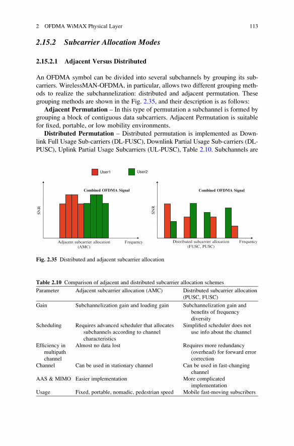
2.15.2 Subcarrier Allocation Modes
2.15.2.1 Adjacent Versus Distributed
An OFDMA symbol can be divided into several subchannels by grouping its sub-
carriers. WirelessMAN-OFDMA, in particular, allows two different grouping meth-
ods to realize the subchannelization: distributed and adjacent permutation. These
grouping methods are shown in the Fig. 2.35, and their description is as follows:
Adjacent Permutation – In this type of permutation a subchannel is formed by
grouping a block of contiguous data subcarriers. Adjacent Permutation is suitable
for fixed, portable, or low mobility environments.
Distributed Permutation – Distributed permutation is implemented as Down-
link Full Usage Sub-carriers (DL-FUSC), Downlink Partial Usage Sub-carriers (DL-
PUSC), Uplink Partial Usage Subcarriers (UL-PUSC), Table 2.10. Subchannels are
Combined OFDMA Signal
SNR
User1 User2
Adjacent subcarrier allocation(AMC)
Distributed subcarrier allocation(FUSC, PUSC)
Frequency
Combined OFDMA Signal
Frequency
SNR
Fig. 2.35 Distributed and adjacent subcarrier allocation
Table 2.10 Comparison of adjacent and distributed subcarrier allocation schemes
Parameter Adjacent subcarrier allocation (AMC) Distributed subcarrier allocation
(PUSC, FUSC)
Gain Subchannelization gain and loading gain Subchannelization gain and
benefits of frequency
diversity
Scheduling Requires advanced scheduler that allocates
subchannels according to channel
characteristics
Simplified scheduler does not
use info about the channel
Efficiency in
multipath
channel
Almost no data lost Requires more redundancy
(overhead) for forward error
correction
Channel Can be used in stationary channel Can be used in fast-changing
channel
AAS & MIMO Easier implementation More complicated
implementation
Usage Fixed, portable, nomadic, pedestrian speed Mobile fast-moving subscribers
2 OFDMA WiMAX Physical Layer 113

allocated with subcarriers in a pseudorandom way. The subcarriers for a described
subchannel in a specific cell will be different from the subcarriers for that same
subchannel in another cell. For example sub-carriers in subchannel 1 in cell 1 will
be different than the subcarriers in the subchannel 1 in cell number 2. The
pseudorandom calculation for the permutations gives an interference averaging
by minimizing the bad effects of cell to cell interference.
2.15.2.2 OFDMA Frame
In IEEE 802.16e-2005 air interface, both FDD and TDD are supported. In case of
FDD, the uplink and downlink sub-frames are transmitted simultaneously on
different carrier frequencies while in the case of TDD, the uplink and downlink
sub-frames are transmitted on the same carrier frequency at different times.
Figure 2.36 shows the frame structure for TDD. For the FDD mode the frame
structure is identical except that the UL and DL sub-frames are multiplexed on
different carrier frequencies. For mobile stations, an additional duplexing mode,
known as H-FDD (half-duplex FDD) is defined. H-FDD is a basic FDD duplexing
scheme with the restriction that the MS cannot transmit and receive at the same
time. From a cost and implementation perspective, an H-FDD MS is cheaper and
k+1 k+3 k+5 k+7 k+9 k+11k+13 k+15 k+17 k+20 k+23
UL burst #1
UL burst #2
UL burst #3
UL burst #4
UL burst #5
UL subframeDL subframe
TTG
DL burst #3
DL burst #4
DL burst #5
DL burst #6DL burst #2
S+L
S+1S+2
S
DL
burs
t #1
(car
ryin
g th
e U
L-M
AP
)
DL-
MA
P
Pre
ambl
e
Sub
chan
nel l
ogic
al n
umbe
r
DL-
MA
P
Pre
ambl
e
Rangaing Subchannel
k+26 k+30 k+31 k+33
t
FCHFCH
k
RTG
Fig. 2.36 Example of an OFDMA frame in TDD mode (adapted from [23])
114 R. Prasad and F.J. Velez

less complex than its FDD counterpart, but the UL and DL peak data rate of, an
H-FDD MS are less, owing to its inability to receive and transmit simultaneously.
An 802.16e TDD frame is built up by one downlink (DL) sub-frame and one
uplink (UL) sub-frame. Each frame in the downlink transmission begins with a
preamble followed by a DL transmission period and an UL transmission period. To
separate the downlink frame from the uplink one, guard zones are inserted as shown
in Fig. 2.36. In the case between the downlink and uplink frame the guard zone is
Transmit Transition Gap (TTG) and between the end of the frame and the next
frame the guard zone is Receive Transition Gap (RTG).
In TDD mode each DL sub-frame and UL sub-frame is divided into various
zones, each using a different subcarrier permutation scheme. Some of the zones,
such as DL PUSC, are mandatory; other zones, such as FUSC, AMC, UL PUSC,
and TUSC, are optional. The relevant information about the starting position and
the duration of the various zones being used in a UL and DL sub-frame is provided
by control messages in the beginning of each DL sub-frame.
The other important sections of the TDD frame are the following:
l Preamble: The first OFDM symbol in the downlink sub-frame is used for
transmitting the DL preamble. The preamble can be used for a variety of PHY
layer procedures, such as time and frequency synchronization, initial channel
estimation, and noise and interference estimation. The subcarriers in the pream-
ble symbol are divided into a group of three carrier sets. The preamble, used for
synchronization, is the first OFDM symbol of the frame.l Frame Control Header (FCH): The FCH follows the preamble. The FCH is
used for carrying system control information, such as the subcarriers used (in
case of segmentation), the ranging subchannels, and the length of the DL-MAP
message. This information is carried on the DL_Frame_Prefix message
contained within the FCH. The FCH is always coded with the BPSK R1/2
mode to ensure maximum robustness and reliable performance, even at the
cell edge. It provides the frame configuration information such as MAP message
length and coding scheme and usable subchannels.l DL-MAP and UL-MAP: The DL-MAP and UL-MAP provide subchannel
allocation and other control information for the DL and UL sub-frames,
respectively.l UL Ranging: The UL ranging subchannel is allocated for mobile stations (MS)
to perform closed-loop time, frequency, and power adjustment as well as
bandwidth requests.
2.15.2.3 Multiple Subcarrier Allocation Zones
OFDMA PHY supports multiple subcarrier allocation zones (such as PUSC, FUSC,
PUSC with all subchannels, optional FUSC, AMC, TUSC1, and TUSC2) within the
same frame to enable the possibility of support for and coexistence of different
types of SSs. Figure 2.37 shows the OFDMA frame with multiple zones.
2 OFDMA WiMAX Physical Layer 115

The switching between zones is performed using an information element
included in DL-MAP and UL-MAP. DL and UL sub-frames both start in PUSC
mode where groups of subchannels are assigned to different segments by the use of
dedicated FCH messages. The PUSC subcarrier allocation zone can be switched to
a different type of subcarrier allocation zone through a directive from the PUSC
DL-MAP. The PHY parameters such as channel state and interference levels may
change from one zone to the next.
2.15.2.4 Time Frequency Mapping
In the OFDMA PHY, the mapping of data to physical subcarriers is performed in
two steps. In the first step, data are mapped to one or more data slots on one or more
logical subchannels. In the second step, for each data slot, each logical subchannel
is then mapped to a number of physical subcarriers.
Logical mapping makes use if certain basic terms in its description described
below.
1. Slot – Slot is the minimum possible data allocation in the time-frequency
domain. It always consists of a single subchannel and two, three or six
OFDM symbols depending on the physical mapping. Size of OFDMA slot
depends on the OFDMA symbol structure, which varies for uplink and down-
link, for FUSC and PUSC, and for the distributed subcarrier permutations and
the adjacent subcarrier permutation.l For downlink FUSC using the distributed subcarrier permutation one slot is
one subchannel by one OFDMA symbol.l For downlink PUSC using the distributed subcarrier permutation one slot is
one subchannel by two OFDMA symbols.l For uplink PUSC using either of the distributed subcarrier permutations one
slot is one subchannel by three OFDMA symbols.
Pre
ambl
e
PU
SC
(fir
stzo
ne c
onta
ins
FC
H a
nd D
L)
PU
SC
(DL_
Per
mB
ase
X)
FU
SC
(ID
L_P
erm
Bas
eZ)
Opt
iona
lF
US
C
FU
SC
(DL_
Per
mB
ase
Y)
AM
C
PU
SC
Opt
iona
lP
US
C
DL subframe UL subframe
Must appear in every frame
May appear in the frame according to mapping
AM
C
TU
SC
1
TU
SC
1
Zone switch IEs in DL-Map
Fig. 2.37 Illustration of the OFDMA frame with multiple zones (adapted from [23])
116 R. Prasad and F.J. Velez
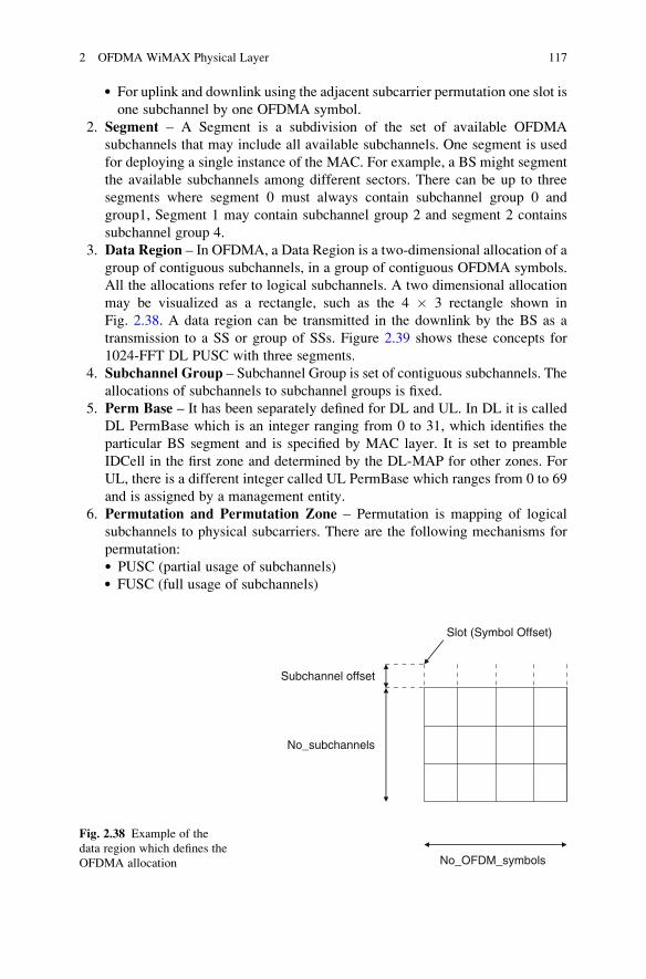
l For uplink and downlink using the adjacent subcarrier permutation one slot is
one subchannel by one OFDMA symbol.
2. Segment – A Segment is a subdivision of the set of available OFDMA
subchannels that may include all available subchannels. One segment is used
for deploying a single instance of the MAC. For example, a BS might segment
the available subchannels among different sectors. There can be up to three
segments where segment 0 must always contain subchannel group 0 and
group1, Segment 1 may contain subchannel group 2 and segment 2 contains
subchannel group 4.
3. Data Region – In OFDMA, a Data Region is a two-dimensional allocation of a
group of contiguous subchannels, in a group of contiguous OFDMA symbols.
All the allocations refer to logical subchannels. A two dimensional allocation
may be visualized as a rectangle, such as the 4 � 3 rectangle shown in
Fig. 2.38. A data region can be transmitted in the downlink by the BS as a
transmission to a SS or group of SSs. Figure 2.39 shows these concepts for
1024-FFT DL PUSC with three segments.
4. Subchannel Group – Subchannel Group is set of contiguous subchannels. The
allocations of subchannels to subchannel groups is fixed.
5. Perm Base – It has been separately defined for DL and UL. In DL it is called
DL PermBase which is an integer ranging from 0 to 31, which identifies the
particular BS segment and is specified by MAC layer. It is set to preamble
IDCell in the first zone and determined by the DL-MAP for other zones. For
UL, there is a different integer called UL PermBase which ranges from 0 to 69
and is assigned by a management entity.
6. Permutation and Permutation Zone – Permutation is mapping of logical
subchannels to physical subcarriers. There are the following mechanisms for
permutation:l PUSC (partial usage of subchannels)l FUSC (full usage of subchannels)
No_OFDM_symbols
No_subchannels
Subchannel offset
Slot (Symbol Offset)
Fig. 2.38 Example of the
data region which defines the
OFDMA allocation
2 OFDMA WiMAX Physical Layer 117

l Optional PUSCl Optional FUSCl AAS (Adaptive Antenna System)l AMC (Adaptive Modulation and Coding)l Option FUSC with all subchannels
Permutation Zone is a number of contiguous OFDMA symbols, in the DL or the
UL, that use the same permutation formula. The permutation formula describes
various configurations of pilot subcarriers, data subcarriers, subchannels, and slots.
The DL sub-frame or the UL sub-frame may contain more than one permutation
zone.
Zones are used to help implement base station functionality such as beamform-
ing, assigning subchannels to different sectors of a single cell, and to define
subchannelization that reduces base station to base station interference.
Data region
slot
Permutation ZoneSubchannelindex
Segment2
Segment1
Segment0
OFDMA Symbol IndexSubchannelgroup index k k+1 k+2 k+3 k+4 k+5 k+6 k+7 k+8 k+9
0123456789
1011121314151617181920212223242526272829
0
1
2
3
4
Fig. 2.39 Schematic indication of logical mapping elements
118 R. Prasad and F.J. Velez

2.15.2.5 Algorithms for OFDMA Data Mapping: Downlink
1. Segment the data after the modulation block into blocks sized to fit into one
OFDMA slot.
2. Each slot should span one subchannels in the subchannel axis and one or more
OFDMA symbols in the time axis. Map the slots such that the lowest numbered
slot occupies the lowest numbered subchannel in the lowest numbered OFDMA
symbol.
3. Continue the mapping such that the OFDMA subchannel index is increased.
When the edge of the Data Region is reached, continue the mapping from the
lowest numbered OFDMA subchannel in the next available symbol.
2.15.2.6 Algorithms for OFDMA Data Mapping: Uplink
The UL mapping consists of two steps. In the first step, the OFDMA slots allocated
to each burst are selected. In the second step, the allocated slots are mapped. Details
are as follows:
Step 1: Allocate OFDMA slots to bursts:
1. Segment the data into blocks sized to fit into one OFDMA slot.
2. Each slot shall span one or more subchannels in the subchannel axis and one or
more OFDMA symbols in the time axis. Map the slots such that the lowest
numbered slot occupies the lowest numbered subchannel in the lowest numbered
OFDMA symbol.
3. Continue the mapping such that the OFDMA symbol index is increased. When
the edge of the UL Zone is reached continue the mapping from the lowest
numbered OFDMA symbol in the next available subchannel.
4. An UL allocation is created by selecting an integer number of contiguous slots,
according to the ordering of steps 1–3. This results in the general Burst structure
shown by the gray area in Fig. 2.40.
Step 2: Map OFDMA slots within the UL allocation:
1. Map the slots such that the lowest numbered slot occupies the lowest numbered
subchannel in the lowest numbered OFDMA symbol.
2. Continue the mapping such that the Subchannel index is increased. When the
last subchannel is reached, continue the mapping from the lowest numbered
subchannel in the next OFDMA symbol that belongs to the UL allocation. The
resulting order is shown by the arrows in Fig. 2.41.
2.15.2.7 Symbol Structure for PUSC
The symbol structure is formed by pilots, data, and zero subcarriers. The symbol is
first divided into basic clusters and zero carriers are allocated. Pilots and data
2 OFDMA WiMAX Physical Layer 119

carriers are allocated within each cluster. Pilot positions are marked separately for
odd and even OFDM symbol. These subcarriers will be separated from the rest
before permutation. For example, consider subcarriers of logical cluster ‘0’ (With
Perm Base = 0, it is the sixth physical cluster). These subcarriers are numbered as
0–13. Their positions with respect to the absolute subcarrier index (0–2047) are
268–281. The pilot subcarriers for odd symbols will be ‘4’ and ‘8’ (‘272’ and ‘276’
with respect to absolute subcarrier index). For even OFDM symbols ‘0’ and ‘12’
(‘268’ and ‘280’) will be pilot positions. The rest 12 subcarriers will be used as data
subcarriers (Fig. 2.42).
Table 2.11 shows the parameters for the symbol structure
OFDMA Symbol Index
Subchannelnumber
slot
slotslot
slot
n n+12n+1
n+11
slot
Data Region
k k+1 k+2 k+3 k+4 k+5 k+6 k+7 k+8 k+9
0123456789
1011121314151617181920212223242526272829
Fig. 2.40 Example of mapping OFDMA slots to subchannels and symbols in the downlink (in the
PUSC mode)
120 R. Prasad and F.J. Velez

Uplink zone
slot
slot
OFDMA Symbol Index
Data Region
Subchannelnumber
slot slotn+11n
n+10
n+22
k k+1 k+2 k+3 k+4 k+5 k+6 k+7 k+8 k+90123456789
1011121314151617181920212223242526272829
Fig. 2.41 Example of mapping OFDMA slots to subchannels and symbols in the uplink
Odd Symbols
Even Symbols
Data Sub-carriers Pilot Sub-carriers
subcarrier
OF
DM
sym
bol
Fig. 2.42 DL PUSC cluster structure
2 OFDMA WiMAX Physical Layer 121
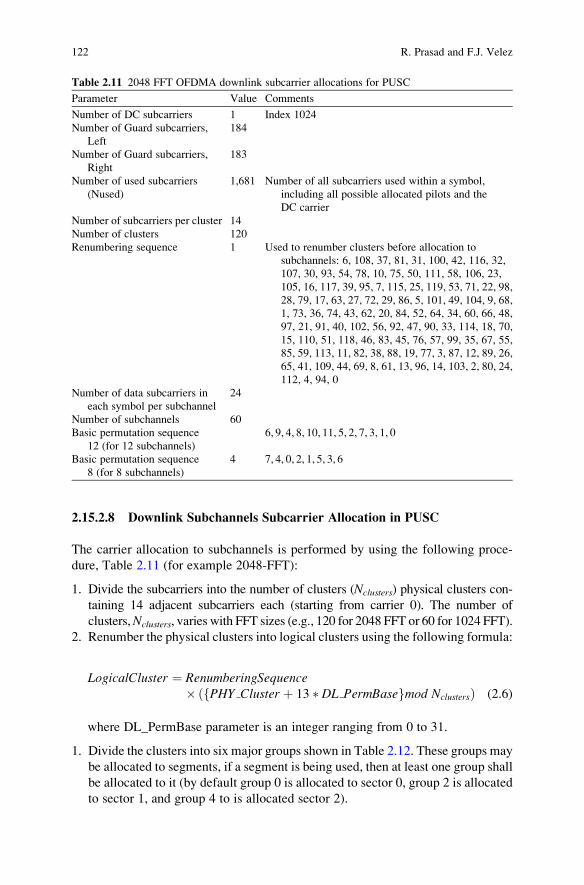
2.15.2.8 Downlink Subchannels Subcarrier Allocation in PUSC
The carrier allocation to subchannels is performed by using the following proce-
dure, Table 2.11 (for example 2048-FFT):
1. Divide the subcarriers into the number of clusters (Nclusters) physical clusters con-
taining 14 adjacent subcarriers each (starting from carrier 0). The number of
clusters,Nclusters, varies with FFT sizes (e.g., 120 for 2048 FFT or 60 for 1024 FFT).
2. Renumber the physical clusters into logical clusters using the following formula:
LogicalCluster ¼ RenumberingSequence�ð PHY Cluster þ 13 � DL PermBasef gmod NclustersÞ (2.6)
where DL_PermBase parameter is an integer ranging from 0 to 31.
1. Divide the clusters into six major groups shown in Table 2.12. These groups may
be allocated to segments, if a segment is being used, then at least one group shall
be allocated to it (by default group 0 is allocated to sector 0, group 2 is allocated
to sector 1, and group 4 to is allocated sector 2).
Table 2.11 2048 FFT OFDMA downlink subcarrier allocations for PUSC
Parameter Value Comments
Number of DC subcarriers 1 Index 1024
Number of Guard subcarriers,
Left
184
Number of Guard subcarriers,
Right
183
Number of used subcarriers
(Nused)
1,681 Number of all subcarriers used within a symbol,
including all possible allocated pilots and the
DC carrier
Number of subcarriers per cluster 14
Number of clusters 120
Renumbering sequence 1 Used to renumber clusters before allocation to
subchannels: 6, 108, 37, 81, 31, 100, 42, 116, 32,
107, 30, 93, 54, 78, 10, 75, 50, 111, 58, 106, 23,
105, 16, 117, 39, 95, 7, 115, 25, 119, 53, 71, 22, 98,
28, 79, 17, 63, 27, 72, 29, 86, 5, 101, 49, 104, 9, 68,
1, 73, 36, 74, 43, 62, 20, 84, 52, 64, 34, 60, 66, 48,
97, 21, 91, 40, 102, 56, 92, 47, 90, 33, 114, 18, 70,
15, 110, 51, 118, 46, 83, 45, 76, 57, 99, 35, 67, 55,
85, 59, 113, 11, 82, 38, 88, 19, 77, 3, 87, 12, 89, 26,
65, 41, 109, 44, 69, 8, 61, 13, 96, 14, 103, 2, 80, 24,
112, 4, 94, 0
Number of data subcarriers in
each symbol per subchannel
24
Number of subchannels 60
Basic permutation sequence
12 (for 12 subchannels)
6, 9, 4, 8, 10, 11, 5, 2, 7, 3, 1, 0
Basic permutation sequence
8 (for 8 subchannels)
4 7, 4, 0, 2, 1, 5, 3, 6
122 R. Prasad and F.J. Velez

2. Allocate carriers to subchannel in each major group is performed by first allo-
cating the pilot carriers within each cluster, and then taking all remaining data
carriers within the symbol. First the six major groups are regrouped into 6 sets of
24 groups, with the pilot tones in each constituent logical cluster excluded. Each
of the even numbered major groups (i.e., group 0, 2 and 4) contains 12 logical
clusters and each of the odd numbered groups (i.e., groups 1, 3 and 5) contains
eight logical clusters, with each cluster carrying 12 data subcarriers and two pilot
tones. For the even numbered major groups, each cluster is divided into two
groups with six data subcarriers each; for the odd numbered major groups, each
cluster is divided into three groups with four data subcarriers each.
3. The subcarriers in each of the 24 groups are mapped into six subchannels or four
subchannels using the following equation called permutation formula.
subcarrierðk; sÞ¼Nsubchannels �nkþ ps nk Nsubchannels½ �fþDL PermBasegNsubchannels ð2:7Þ
where:
Subcarrier(k, s) is the subcarrier index of subcarrier k in subchannel s,k is the subcarrier-in-subchannel index from the set [0. . .Nsubchannels-1]s is the index number of a subchannel, from the set [0. . .Nsubchannels-1],Nsubchannels is the number of subchannels in the current Major group
nk = (k + 13 s) mod Nsubcarriers
ps[j] is the series obtained by rotating basic permutation sequence cyclically to
the left s times,
DL_PermBase is an integer ranging from 0 to 31, which is set to preamble IDCell in the
first zone and determined by the DL-MAP for other zones.
A comparison of subcarrier allocations in the 1024 FFT OFDMA System is
presented in Table 2.13. The comparison is performed among DL PUSC, DL
FUSC, UL PUSC and DL/UL AMC.
2.15.2.9 Symbol Structure for FUSC
The symbol structure is constructed using pilots, data, and zero subcarriers. The
symbol is first allocated with the appropriate pilots and with zero subcarriers, and
then all the remaining subcarriers (Table 2.14) are used as data subcarriers which
are later divided into subchannels.
There are two variable pilot-sets and two constant pilot-sets. The fixed sets are
divided into subset that are used in odd and even symbols respectively. This
Table 2.12 Clusters and
respective groupsGroup Clusters
Group 0 0–23
Group 1 24–39
Group 2 40–63
Group 4 64–79
Group 5 80–103
Group 6 104–119
2 OFDMA WiMAX Physical Layer 123

provides a tradeoff between allocated power and frequency diversity on pilots for
channel estimation. Table 2.15 shows the distribution of fixed and variable sets of
pilots for 2048 FFT while Tables 2.16 and 2.17 presents the respective distributions
for 1024 FFT and 512 FFT, respectively.
2.15.2.10 Downlink Subchannels Subcarrier Allocation in PUSC
The carrier allocation to subchannels is performed using the following procedure,
as shown in Fig. 2.43:
1. Divide the subcarriers into the number of physical clusters (Nclusters), con-
taining 14 adjacent subcarriers each (starting from carrier 0). The number
Table 2.13 Subcarrier allocations in the 1024 FFT OFDMA system
Parameters DL PUSC DL FUSC UL PUSC DL/UL AMC
Number of DC subcarriers 1 1 1 1
Number of guard subcarriers, left 92 87 92 80
Number of guard subcarriers, right 91 86 91 79
Number of pilot subcarriers 120 82 420/0 96
Number of data subcarriers 720 768 420/840 768
Number of subchannels 30 16 35 48
Number of data subcarriers in each
symbol per subchannel
24 48 12/24 16
Number of clusters 60
Number of subcarriers per cluster 14
Number of tiles 210
Number of subcarriers per tile 4
Number of tiles per subchannel 6
Number of bins 96
Number of subcarriers per bin 9
Number of bins per subchannel 2
Table 2.14 OFDMA downlink subcarrier allocations for FUSC
Parameter Value Comments
INumber of DC subcarriers 1 Index 1024
Number of guard
subcarriers, left
160
Number of guard
subcarriers, right
159
Number of used subcarriers,
Nused1,729 Number of all subcarriers used within a symbol,
including all possible allocated pilots and the
DC carrier
Number of data subcarriers 1,536
Number of data subcarriers
per subchannel
48
Number of subchannels 32
PermutationBase 3, 18, 2, 8, 16, 10, 11, 15, 26, 22, 6, 9, 27, 20, 25, 1, 29, 7,
21, 5, 28, 31, 23, 17, 4, 24, 0, 13, 12, 19, 14, 30
124 R. Prasad and F.J. Velez

of clusters, Nclusters, varies with FFT sizes as mentioned in Tables 2.11
and 2.13.
2. Renumber the physical clusters into logical clusters using the following
formula:
Logical Cluster ¼ Renumbering Sequenceð Physical Clusterð Þþ 13 � DL PermBaseÞ ð2:8Þ
Table 2.15 2048-FFT OFDMA downlink carrier allocations – FUSC
Parameter Value Comments
Pilot Subcarrier
Index:
71 0,72,144,216,288,360,432,504,576,648,720,792,864,
936,1008,1080,1152,1224,1296,1368,1440,1512,1584,
1656,48,120,192,264,336,408,480,552,624,696,768,
840,912,984,1056,1128,1200,1272,1344,1416,1488,
1560,1632,24,96,168,240,312,384,456,528,600,672,
744,816,888,960,1032,1104,1176,1248,1320,1392,
1464,1536,1608,1680
VariableSet #0
Pilot Subcarrier
Index:
12 72*(2*n + k) + 9 when k = 0 and n = 0. . ., 5 DC subcarrier shall be
included when the pilot subcarrier index is calculated by the
equationConstantSet #0
Pilot Subcarrier
Index:
71 36,108,180,252,324,396,468,540,612,684,756,
828,12,84,156,228,300,372,444,516,588,660,
732,804,60,132,204,276,348,420,492,564,636, 708,780VariableSet #1
Pilot Subcarrier
Index:
12 72*(2*n + k) + 9 when k = 1 and n = 0. . ., 4 DC subcarrier shall be
included when the pilot subcarrier index is calculated by the
equationConstantSet #1
Basic Permutation
Sequence
– 3, 18, 2, 8, 16, 10, 11, 15, 26, 22, 6, 9, 27, 20, 25, 1, 29, 7, 21, 5, 28,
31, 23, 17, 4, 24, 0, 13, 12, 19, 14, 30
Table 2.16 1024 FFT OFDMA downlink subcarrier allocations – FUSC
Parameter Value Comments
Pilot Subcarrier Index:
VariableSet #0
12 0, 24, 48, 72, 96, 120, 144, 168, 192, 216, 240, 264, 288,
312, 336, 360, 384, 408, 432, 456, 480, 504, 528, 552,
576, 600, 624, 648, 672, 696, 720, 744, 768, 792, 816,
840
Pilot Subcarrier Index:
ConstantSet #0
2 72*(2*n + k) + 9 when k = 0 and n = 0. . ., 5 DC subcarrier shall
be included when the pilot subcarrier index is calculated by
the equation
Pilot Subcarrier Index:
VariableSet #1
12 36, 108, 180, 252, 324, 396, 468, 540, 612, 684, 756,
828, 12, 84, 156, 228, 300, 372, 444, 516, 588, 660,
732, 804, 60, 132, 204, 276, 348, 420, 492, 564, 636,
708, 780
Pilot Subcarrier Index:
ConstantSet #1
2 72*(2*n + k) + 9 when k ¼ 1 and n ¼ 0. . . , 4 DC subcarrier
shall be included when the pilot subcarrier index is
calculated by the equation
Basic Permutation
Sequence
– 6, 14, 2, 3, 10, 8, 11, 15, 9, 1, 13, 12, 5, 7, 4, 0
2 OFDMA WiMAX Physical Layer 125

3. Logical clusters of step 2 are grouped together to form six major groups. These
groups are numbered from 0 to 5. The allocation algorithm varies with FFT sizes
as follows:l FFT size = 2048 – The clusters are divided into six major groups. Group
0 includes clusters 0–23, group 1 includes clusters 24–39, group 2 includes
clusters 40–63, group 3 includes clusters 64–79, group 4 includes clusters
80–103, group 5 includes clusters 104–119. These groups may be allocated to
segments, if a segment is being used, then at least one group shall be allocated
to it (by default group 0 is allocated to sector 0, group 2 is allocated to sector 1,
and group 4 to is allocated sector 2).l FFT size = 512 – The clusters are divided into six major groups. Group
0 includes clusters 0–9, group 2 includes clusters 10–19, group 4 includes
clusters 20–29. These groups may be allocated to segments, if a segment is
being used, then at least one group shall be allocated to it (by default group
0 is allocated to sector 0, group 2 is allocated to sector 1, and group 4 to is
allocated sector 2).
Table 2.17 FFT OFDMA downlink subcarrier allocations – FUSC
Parameter Value Comments
Pilot Subcarrier Index:
VariableSet #0
18 0, 24, 48, 72, 96, 120, 144, 168, 192, 216, 240, 264, 288,
312, 336, 360, 384, 408
Pilot Subcarrier Index:
ConstantSet #0
3 72*(2*n + k) + 9 when k ¼ 0 and n ¼ 0. . . , 2 DC subcarrier
shall be included when the pilot subcarrier index is
calculated by the equation
Pilot Subcarrier Index:
VariableSet #1
18 12, 36, 60, 84, 108, 132, 156, 180, 204, 228, 252, 276,
300, 324, 348, 372, 396, 420
Pilot Subcarrier Index:
ConstantSet #1
3 72*(2*n + k) + 9 when k ¼ 1 and n ¼ 0. . . , 2 DC subcarrier
shall be included when the pilot subcarrier index is
calculated by the equation
Basic Permutation
Sequence
– 2, 0, 1, 6, 4, 3, 5, 7
Physical clusterNo. ‘0’
Physical clusterNo. ‘1’
184 GuardSubcarriers
One cluster14 Subcarriers
183 GuardSubcarriers
DC Subcarrier
Physical clusterNo. ‘119’
20 MHz
Total Subcarriers (1440 Data + 240 Pilot + 1 DC) = 1681
Fig. 2.43 Downlink subchannels subcarrier allocation in PUSC
126 R. Prasad and F.J. Velez

l FFT size = 128 – The clusters are divided into six major groups. Group
0 includes clusters 0–1, group 2 includes clusters 2–3, group 4 includes
clusters 4–5. These groups may be allocated to segments, if a segment is
being used, then at least one group shall be allocated to it (by default group
0 is allocated to sector 0, group 2 is allocated to sector 1, and group 4 to is
allocated sector 2).
4. Allocate subcarriers to subchannel in each major group is performed separately
for each OFDMA symbol by first allocating the pilot carriers within each cluster,
and then taking all remaining data carriers within the symbol and using the
Permutation Formula defined in FUSC subcarrier allocation. The parameters
vary with FFT sizes as follows:l FFT size = 2048 – Use the parameters from Table 2.15, with basic permuta-
tion sequence 12 for even numbered major groups, and basic permutation
sequence 8 for odd numbered major groups, to partition the subcarriers into
subchannels containing 24 data subcarriers in each symbol.l FFT size = 1024 – Use the parameters from Table 2.16, with basic per-
mutation sequence 6 for even numbered major groups, and basic
permutation sequence 4 for odd numbered major groups, to partition the
subcarriers into
2.15.2.11 PUSC UL
One slot of PUSC UL is three OFDM symbols by one subchannel. Out of 2,048,
there are 184 left guard subcarriers, 183 right guard subcarriers and one DC
subcarrier. There are ‘840 data + 840 pilot’ subcarriers for even numbered
OFDM symbols and ‘1680 data + 0 pilot’ for odd numbered OFDM symbols.
Figure 2.44 shows how pilots are marked for even numbered OFDM symbols and
also it points out the absence of pilot carriers during odd symbol.
2.15.2.12 Adjacent Subcarrier Permutation
OFDMA PHY supports AAS and also a set of second-, third-, and fourth-order
transmit diversity options. With the AAS option, the system uses a multiple-
Data Sub - carriers Pilot Sub - carriers
Symbol 0
Symbol 1
Symbol 2
Fig. 2.44 UL PUSC tile
structure
2 OFDMA WiMAX Physical Layer 127

antenna transmission to improve the coverage and capacity of the system while
minimizing the probability of outage through transmit diversity, beam forming and
null steering.
An AAS DL Zone begins on the specified symbol boundary and consists of all
subchannels until the start of the next Zone or end of frame. The two highest
numbered subchannels of the DL frame may be dedicated at the discretion of the BS
for the AAS Diversity-Map Zone in PUSC, FUSC, and optional FUSC permutation.
It should be noted that AAS Diversity-Map Zone shall is used only with FFT sizes
greater than or equal to 512.
In the AMC permutation, first and last subchannels of the AAS DL Zone may be
dedicated at the discretion of the BS for the AAS Diversity-Map Zone as shown in
the Fig. 2.45. When first and the last subchannels are used for Diversity-Map zone,
they are not allocated in the normal DL-MAP message but are used to transmit the
AAS-DLFP(). In case that the AAS Diversity-Map zone is not included in the AAS
zone, these subchannels may be used for ordinary traffic and may be allocated in
DL_MAP messages.
For all AMC permutations in an AAS zone including the optional AAS
Diversity-Map zone, two bin by three symbol tile structure is used. In the AAS
zone, the same antenna beam pattern shall be used for all pilot subcarriers and data
subcarriers in a given AMC subchannel.
DL burst #5
DL burst #4
DL burst #3
DL burst #2
DL burst #1
Pre
ambl
e
DL-
MA
P
FCH
DL subframe
UL-
MA
P
AAS diversity map zone
PUSCpermutation AAS on FUSC/PUSC
permutation
DL burst #4
DL burst #3DL burst #2
DL burst #1
Pre
ambl
e
DL-
MA
P
FCH
DL subframe
UL-
MA
P
AAS diversity map zone (subchannel N-1)
PUSCpermutation AAS on AMC permutation
AAS diversity map zone ( subchannel 0)
Fig. 2.45 AAS diversity map frame structure
128 R. Prasad and F.J. Velez
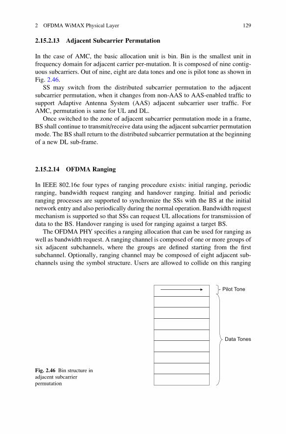
2.15.2.13 Adjacent Subcarrier Permutation
In the case of AMC, the basic allocation unit is bin. Bin is the smallest unit in
frequency domain for adjacent carrier per-mutation. It is composed of nine contig-
uous subcarriers. Out of nine, eight are data tones and one is pilot tone as shown in
Fig. 2.46.
SS may switch from the distributed subcarrier permutation to the adjacent
subcarrier permutation, when it changes from non-AAS to AAS-enabled traffic to
support Adaptive Antenna System (AAS) adjacent subcarrier user traffic. For
AMC, permutation is same for UL and DL.
Once switched to the zone of adjacent subcarrier permutation mode in a frame,
BS shall continue to transmit/receive data using the adjacent subcarrier permutation
mode. The BS shall return to the distributed subcarrier permutation at the beginning
of a new DL sub-frame.
2.15.2.14 OFDMA Ranging
In IEEE 802.16e four types of ranging procedure exists: initial ranging, periodic
ranging, bandwidth request ranging and handover ranging. Initial and periodic
ranging processes are supported to synchronize the SSs with the BS at the initial
network entry and also periodically during the normal operation. Bandwidth request
mechanism is supported so that SSs can request UL allocations for transmission of
data to the BS. Handover ranging is used for ranging against a target BS.
The OFDMA PHY specifies a ranging allocation that can be used for ranging as
well as bandwidth request. A ranging channel is composed of one or more groups of
six adjacent subchannels, where the groups are defined starting from the first
subchannel. Optionally, ranging channel may be composed of eight adjacent sub-
channels using the symbol structure. Users are allowed to collide on this ranging
Pilot Tone
Data Tones
Fig. 2.46 Bin structure in
adjacent subcarrier
permutation
2 OFDMA WiMAX Physical Layer 129

channel. To effect a ranging transmission, each user randomly chooses one ranging
code from a bank of specified binary codes. These codes are then BPSK modulated
onto the subcarriers in the ranging channel, one bit per subcarrier. The initial
ranging transmission is used by any SS that wants to synchronize to the system
channel for the first time.
An initial-ranging transmission is performed during two or four consecutive
symbols. The same ranging code is transmitted on the ranging channel during each
symbol, with no phase discontinuity between the two symbols. A time-domain
illustration of the initial-ranging/handover-ranging transmission is shown in
Fig. 2.47.
The BS can allocate two consecutive initial-ranging/handover-ranging slots,
Fig. 2.48. The SS then transmits the two consecutive initial-ranging/handover-
ranging codes. The SS can also optionally use two consecutive ranging codes
transmitted during a four-OFDM symbol period. This option decreases the proba-
bility of failure and increases the ranging capacity to support larger numbers of
Copy samples Copy samples
OFDM symbol period OFDM symbol period
CP CP
time
Fig. 2.47 Initial ranging transmissions for OFDMA (adapted from [23])
Copy samples
OFDM symbol period
Code XCode X Code (X+1) Code (X+1)
Copy samples
OFDM symbol period
Copy samples
CPCP
Copy samplesCopy samples
time
Fig. 2.48 Initial ranging transmission for OFDMA, using two consecutive initial ranging codes
130 R. Prasad and F.J. Velez

simultaneous ranging SSs while at the same time it further increases the capability
of the system to support larger numbers of synchronization mismatches [35]. For
this the starting code should always be multiple of 2.
2.15.2.15 Ranging Codes
The ranging codes are binary pseudo-noise codes produced by the PRBS gene-
rator. A set of 256 special pseudo-noise 144 bit-long ranging codes are divided
into four groups for Initial Ranging, Periodic Ranging, Bandwidth Requests and
Handover Ranging such that the BS can determine the purpose of the received
code by the subset to which the code belongs. From the available codes, the first
N are for initial ranging, the next M are for periodic ranging, the next L for
bandwidth request and the remaining S (S = 144-N-M-L) are for Handover ranging[30, 36].
2.15.2.16 Channel Coding
For OFDMA PHY, channel coding procedures include randomization, FEC encod-
ing, bit interleaving, and modulation.
As shown in the Fig. 2.49, the basic block pass the regular coding chain where
the first subchannel set the randomization seed, and the data follow the coding chain
up to the mapping. The output data from the modulation is mapped onto the block
of subchannels allocated for the basic block. Then, it is also mapped on the
allocated subchannels.
2.15.2.17 Randomization
Data randomization is performed on all data transmitted on the downlink as well as
uplink except the FCH. The randomization is initialized on each FEC block. If the
amount of data to transmit does not fit exactly the amount of data allocated, padding
of 0xFF (“1” only) shall be added to the end of the transmission block, up to the
amount of data allocated. Here, the amount of data allocated means the amount of
data that corresponds to the amount of [Ns/R] slots, where Ns is the number of the
slots allocated for the data burst and R is the repetition factor used.
Randomizer FEC Bit-Interleaver ModulationData to inPHY burst
Mapping toOFDMAsubchannels
Repetition
Fig. 2.49 Channel coding process for regular and repetition coding transmission
2 OFDMA WiMAX Physical Layer 131

2.15.2.18 Encoding
The encoding block size depends on the number of slots allocated and the modula-
tion specified for the current transmission. Concatenation of a number of slots is
performed in order to make larger blocks of coding where it is possible, with the
limitation of not exceeding the largest supported block.
The OFDMA PHY supports mandatory tail-biting Convolutional Coding and
three optional coding schemes. Zero Tailing Convolutional code, Convolutional
Turbo code along with HARQ, and Block Turbo code are the optional coding
schemes.
The tail biting is implemented by initializing the encoders memory with the last
data bits of the FEC block being encoded, and the zero tailing is implemented by
appending a zero tail byte to the end of each burst.
HARQ mitigates the effect of impairments due to channel and external interfer-
ence by effectively employing time diversity along with incremental transmission
of parity codes (subpackets in this case). In the receiver, previously erroneously
decoded subpackets and retransmitted subpackets are combined to correctly decode
the message. The transmitter decides whether to send additional subpackets, based
on ACK/NAK messages received from the receiver.
2.15.2.19 Bit Interleaving
Bit interleaving is done in order to protect the transmission against long sequences
of consecutive errors, which are very difficult to correct. Interleaving process is
performed on encoded data at the output of FEC. The size of the interleaving block
is based on the number of coded bits per encoded block size. The interleaving is
performed using a two-step permutation process. The first permutation ensures that
adjacent coded bits are mapped onto nonadjacent subcarriers and the second per-
mutation ensures that adjacent coded bits are mapped alternately onto less or more
significant bits of the constellation, thus avoiding long runs of lowly reliable bits.
2.15.2.20 Repetition
The Repetition process was added in Channel Coding in IEEE 802.16e standard for
PFDMA PHY [24]. Repetition coding is used to further increase signal margin over
the modulation and FEC mechanisms.
In the case of repetition coding, R = 2, 4, or 6, the number of allocated slots (Ns)will be a whole multiple of the repetition factor R for uplink. For the downlink, the
number of the allocated slots (Ns) will be in the range of R � K, R � K + (R�1),
where K is the number of the required slots before applying the repetition scheme.
For example, when the required number of slots before the repetition is 10( = K) andthe repetition of R = 6 will be applied for the burst transmission, then the number of
the allocated slots (Ns) for the burst can be from 60 slots to 65 slots.
132 R. Prasad and F.J. Velez

The binary data that fits into a region that is repetition coded is reduced by a
factor R compared to a non-repeated region of the slots with the same size and FEC
code type. After FEC and bit-interleaving, the data is segmented into slots, and each
group of bits designated to fit in a slot will be repeated R times to form R contiguous
slots following the normal slot ordering that is used for data mapping.
This repetition scheme applies only to QPSK modulation; it can be applied in all
coding schemes except HARQ with CTC.
2.16 Summary and Conclusions
This Chapter covers aspects of OFDM and OFDMA WiMAX physical layer. It
started by presenting the historical evolution of OFDM, OFDM fundamentals and
the OFDM transmission concept, including details on the serial to parallel converter
and the role of the demodulator. The OFDM symbol time structure was presented
and ISI and ICI mitigation was discussed together with details on OFDM spectral
efficiency and the impact of subchannelisation, which shows the advantages of
OFDM. Robustness against narrowband interference, simple equalisation, low cost
transmitter, simple receiver, sub-carrier rate adaptation and resistance against
selective fading are amongst the advantages of OFDM.
The parameters and principles of Scalable OFDMA were also addressed and
its usefulness in IEEE 802.16e was highlighted, as it enables that IEEE 802.16e
may be backward compatible with FBWA IEEE 802.16-2004. Finally, the IEEE
802.16 PHY layer was described in detail, including aspects of WirelessMAN-SC,
WirelessMAN-OFDM, WirelessMAN-OFDMA and WirelessMAN-HUMAN
PHYs.
References
1. R.V. Nee, R. Prasad, OFDM for Wireless Multimedia Communications (Artech House,
Boston, MA, 2000)
2. M.I. Rahman, S.S. Das, F.H.P. Fitzek, OFDM Based WLAN Systems (Aalborg University,
Denmark, Jan 2004). Technical Report R- 4-1002, ISSN 0908-1224, ISBN 87-90834-43-7
3. R.W. Chang, Synthesis of band-limited orthogonal signals for multichannel data transmission.
Bell Syst. Tech. J. (Dec 1966)
4. J.L. Holsinger, Digital communication over fixed time continuous channels with memory,
with special application to telephone channels, Ph.D. thesis, Massachusetts Institute of
Technology, Cambridge, MA, 1964
5. R.G. Gallager, Information Theory and Reliable Communications (Wiley, New York, 1968)
6. B.R. Saltzberg, Performance of an efficient parallel data transmission system. IEEE Trans.
Commun. 15(6), 805–811 (1967)
7. S.B. Weinstein, P.M. Ebert, Data transmission of frequency division multiplexing using the
discrete frequency transform. IEEE Trans. Commun. COM-19(5), 623–634 (Oct 1971)
2 OFDMA WiMAX Physical Layer 133

8. R. Peled, A. Ruiz, Frequency domain data transmission using reduced computational com-
plexity algorithms, in Proceeding of the IEEE International Conference on Acoustics, Speech,and Signal Processing, ICASSP ’80 (Denver, CO, USA, 1980), pp. 964–967
9. L.J. Cimini, Analysis and simulation of a digital mobile channel using orthogonal frequency
division multiplexing. IEEE Trans. Commun. 33(7), 529–540 (July 1985)
10. S.S. Das, Techniques to enhance spectral efficiency of OFDM Systems, Ph.D. thesis, Aalborg
University, Denmark, 2007
11. M.A. Hasan, Performance Evaluation of WiMAX/IEEE 802.16 OFDM Physical Layer,
Master’s thesis presentation, Helsinki University, Finland, 2007
12. E.P. Lawrey, Adaptive Techniques for Multiuser OFDM, Ph.D. dissertation, James Cook
University, Australia, Dec 2001
13. C.R. Nassar et al., Multi-carrier Technologies for Wireless Communication (Kluwer, Norwell,
MA, 2002)
14. M.I. Rahman, S.S. Das, F.H.P. Fitzek, OFDM Based WLAN Systems (Aalborg University,
Denmark, 2005). Technical Report R-04-1002; v1.2, 2005
15. H. Rohling et al., Broad-band OFDM Radio transmission for multimedia applications. Proc.
IEEE 87(10), 1778–1789 (Oct 1999)
16. J. Geier, Wireless LANs, Implementing High Performance IEEE 802.11 Networks, 2nd ed.
(Sams Publishing, Indianapolis, IN, July 2001)
17. D. Matic, OFDM Synchronization and Wideband Power Measurements at 60 GHz for Future
Wireless Broadband Multimedia Communications, Ph.D. dissertation, Aalborg University,
Denmark, Sept 2001
18. U.S. Jha, Low Complexity Resource Efficient OFDM Based Transceiver Design, Ph.D.
dissertation, Aalborg University, Denmark, Sept 2002
19. IEEE 802.16-2004, IEEE Standard for Local and metropolitan area networks – Part 16: Air
Interface for Fixed Broadband Wireless Access Systems, June 24, 2004
20. J.H. Scott, The How and Why of COFDM. BBC Research and Development, EBU Technical
Review, Winter 1999
21. H. Sari et al., Transmission techniques for digital terrestrial TV broadcasting. IEEE Commun.
Mag. 33(2), 100–109 (Feb 1995)
22. H. Rohling, T. May, Comparison of PSK and DPSKModulation in a Coded OFDM System, in
Proceedings of IEEE VTC, Phoenix, Arizona, USA, 1997, pp. 5–723. IEEE P802.16e/D9 Part 16: Air Interface for Fixed and Mobile Broadband Wireless Access
Systems: Amendment for Physical and Medium Access Control Layers for Combined Fixed
and Mobile Operation in Licensed Bands, IEEE, New York, June 2005
24. IEEE P802.16-2004/Cor1/D3 Corrigendum to IEEE Standard for Local and Metropolitan
Area Networks–Part 16: Air Interface for Fixed Broadband Wireless Access Systems, IEEE,
New York, 2005
25. Channel Models for Fixed Wireless Applications, IEEE 802.16 Broadband Wireless Access
Working Group, http://ieee802.org/16, IEEE, New York, 2003
26. D.C. Cox, 910 MHz Urban mobile radio propagation: multipath characteristics in New York
City. IEEE Trans. Commun. com-21(11) (Nov 1973)
27. D.H. Morais, Fixed Broadband Wireless Communications: Principles and Practical Applica-tions, 1st ed. (Prentice Hall, Upper Saddle River, NJ, Jan 2004)
28. H. Yaghoobi, Scalable OFDMA Physical layer in IEEE 802.16 wireless MAN. Intel Technol.
J. 8(3) (2004)
29. C. Eklund, R.B. Marks, K.L. Stanwood, S. Wang, IEEE Standard 802.16: A Technical
Overview of the WirelessMAN Air Interface for Broadband Wireless Access (June 2002)
30. IEEE Std 802.16e-2005 and IEEE Std 802.162004/Cor 12005 (Amendment and Corrigendum
to IEEE Std 802.16-2004), IEEE Standard for Local and metropolitan area networks Part 16:
Air Interface for Fixed and Mobile Broadband Wireless Access Systems Amendment 2:
Physical and Medium Access Control Layers for Combined Fixed and Mobile Operation in
Licensed Bands and Corrigendum 1 (Feb 2006)
134 R. Prasad and F.J. Velez

31. H. Sari, G. Karam, Orthogonal frequency-division multiple access and its application to
CATV networks. Eur. Trans. Telecommun. (ETT) 9(6), 507–516 (Nov–Dec 1998)
32. A. Ghosh, D.R. Wolter, J.G. Andrews, R. Chen, Broadband wireless access with WiMax/
802.16: current performance benchmarks and future potential. IEEE Commun. Mag. 43(2)
(Feb 2005)
33. http://en.wikipedia.org/wiki/OFDM#cite_note-4 (March 2010)
34. http://www.umtsforum.com (March 2010)
35. H. Yaghoobi, Scalable OFDMA Physical Layer in IEEE 802.16 WirelessMAN. Intel Com-
munications Group, Intel Corporation, Santa Clara, CA, USA (August 2004)
36. A. Ghost, R. Muhamed, J.G. Andrews, Fundamentals of WiMAX: Understanding BroadbandWireless Networking (Prentice Hall, Upper Saddle River, NJ, 2007)
2 OFDMA WiMAX Physical Layer 135

http://www.springer.com/978-90-481-8751-5
Recommended