CCHHAAIINN DDRRIIVVEE IINNDDOOOORR CCYYCCLLIINNGG BBIIKKEE
SSFF--BB11000022CC
OOWWNNEERR’’SS MMAANNUUAALL
IMPORTANT!
PLEASE READ THIS MANUAL CAREFULLY BEFORE USING THE BIKE.
For Customer Service, please contact: [email protected]

Important Safety Information
Please keep this manual for future reference.
1. It is important to read this entire manual before assembling and using the
equipment. Safe and effective use can only be achieved if the equipment is
assembled, maintained and used properly. It is your responsibility to ensure
that all users of the equipment are informed of all warnings and precautions.
2. Before starting any exercise program you should consult your doctor to
determine if you have any medical or physical conditions that could put your
health and safety at risk, or prevent you from using the equipment properly.
Your doctor’s advice is essential if you are taking medication that affects
your heart rate, blood pressure or cholesterol level.
3. Be aware of your body’s signals. Incorrect or excessive exercise can
damage your health. Stop exercising if you experience any of the following
symptoms: pain, tightness in your chest, irregular heartbeat, extreme
shortness of breath, lightheadedness, dizziness or feelings of nausea. You
should consult your doctor before continuing with your exercise program. If
you do experience any of these conditions.
4. Keep children and pets away from the equipment. The equipment is
designed for adult use only.
5. Use the equipment on a solid, flat level surface with a protective cover for
your floor or carpet. The equipment should have at least 0.5 meters of free
space all around to ensure the safety.
6. Check all the nuts and bolts securely tightened before using the equipment.
7. The safety of the equipment can only be maintained if it is regularly
examined.
8. Always use the equipment as indicated. If you find any defective
components while assembling or checking the equipment, or if you hear any
unusual noises coming from the equipment during exercise, stop using the
equipment immediately and don’t use the equipment until the problem has
been repaired.
9. Wear suitable clothing while using the equipment. Avoid wearing loose
clothing that may get caught in the equipment
10. The maximum weight capacity of this unit is 275 pounds.
11. The equipment is not suitable for therapeutic use.
12. You must take care of yourself when lifting and moving the equipment so as
not to injure your back. Always use proper lifting technique and seek
assistance if necessary.
13. This equipment is designed for indoor and home use only, not intended for
commercial use.
1
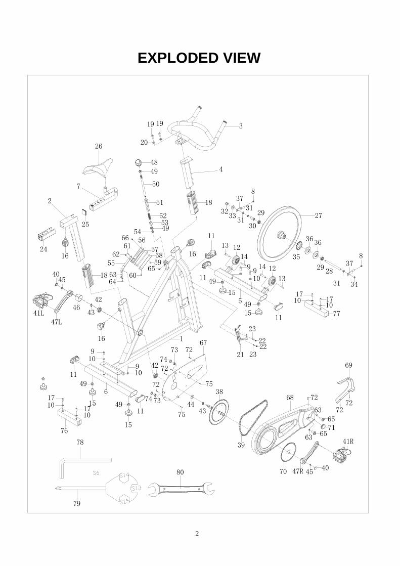
EXPLODED VIEW
1
2
3
4
5
6
7
9
910
10
910
9
11
11
11
11
12
12
13
13
14
15
15
15
15
16
18
19 19
20
2122
23
22
23
1624
25
18
26
27
2829
29
30
31
3132
33
34
38
47R
47L
39
40
40
41L
42
42
43
4344
45
46
4849
50
51
52
54
55
56
5859
60
62
6463
61
4953
67
68
69
71
45
65
65
72
72
72
74
73
737472
72
75
75
63
63
72
5714
65
76
80
79
41R
35
3636
37
37
8
8
16
66
31
70
1710
1710
1710 17
1077
78
49
49
49
49
11
2
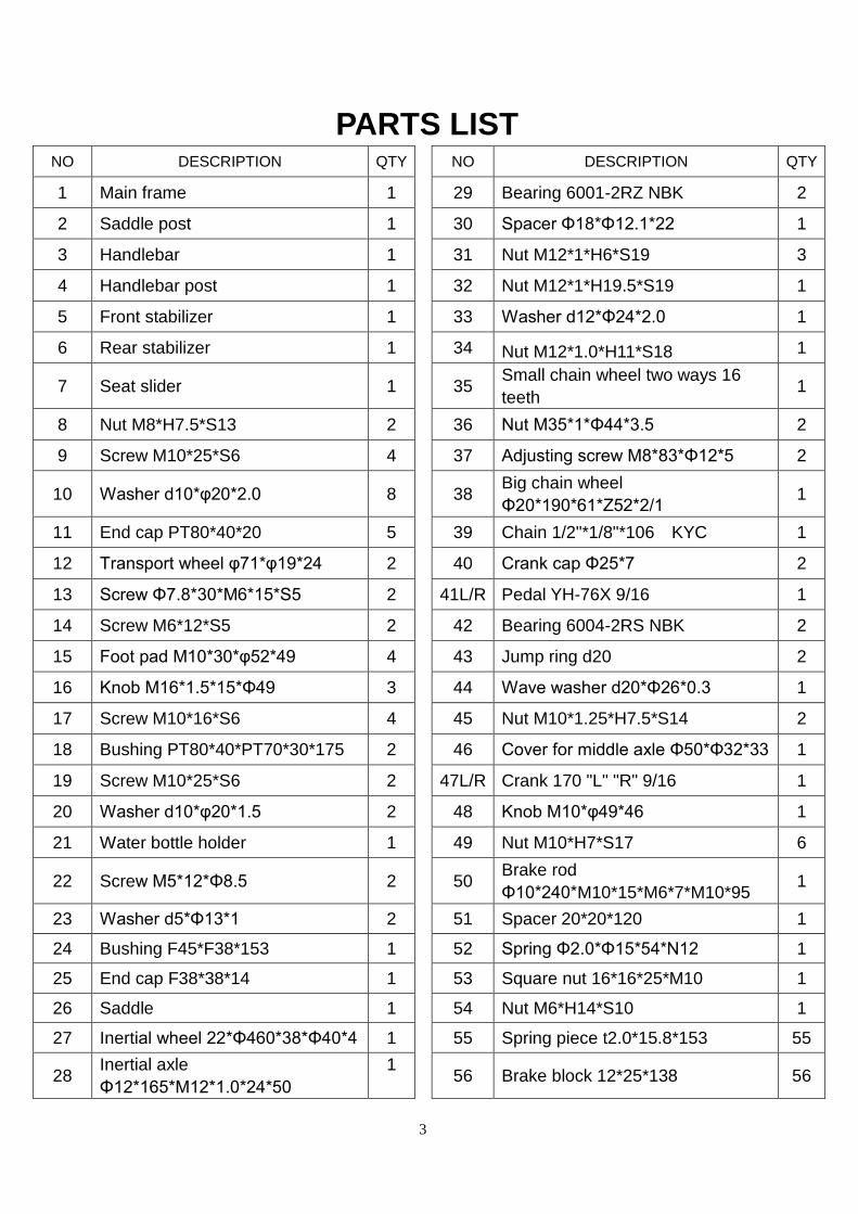
PARTS LIST NO DESCRIPTION QTY NO DESCRIPTION QTY
1 Main frame 1 29 Bearing 6001-2RZ NBK 2
2 Saddle post 1 30 Spacer Φ18*Φ12.1*22 1
3 Handlebar 1 31 Nut M12*1*H6*S19 3
4 Handlebar post 1 32 Nut M12*1*H19.5*S19 1
5 Front stabilizer 1 33 Washer d12*Φ24*2.0 1
6 Rear stabilizer 1 34 Nut M12*1.0*H11*S18 1
7 Seat slider 1 35 Small chain wheel two ways 16
teeth 1
8 Nut M8*H7.5*S13 2 36 Nut M35*1*Φ44*3.5 2
9 Screw M10*25*S6 4 37 Adjusting screw M8*83*Φ12*5 2
10 Washer d10*φ20*2.0 8 38 Big chain wheel
Φ20*190*61*Z52*2/1 1
11 End cap PT80*40*20 5 39 Chain 1/2"*1/8"*106 KYC 1
12 Transport wheel φ71*φ19*24 2 40 Crank cap Φ25*7 2
13 Screw Φ7.8*30*M6*15*S5 2 41L/R Pedal YH-76X 9/16 1
14 Screw M6*12*S5 2 42 Bearing 6004-2RS NBK 2
15 Foot pad M10*30*φ52*49 4 43 Jump ring d20 2
16 Knob M16*1.5*15*Φ49 3 44 Wave washer d20*Φ26*0.3 1
17 Screw M10*16*S6 4 45 Nut M10*1.25*H7.5*S14 2
18 Bushing PT80*40*PT70*30*175 2 46 Cover for middle axle Φ50*Φ32*33 1
19 Screw M10*25*S6 2 47L/R Crank 170 "L" "R" 9/16 1
20 Washer d10*φ20*1.5 2 48 Knob M10*φ49*46 1
21 Water bottle holder 1 49 Nut M10*H7*S17 6
22 Screw M5*12*Φ8.5 2 50 Brake rod
Φ10*240*M10*15*M6*7*M10*95 1
23 Washer d5*Φ13*1 2 51 Spacer 20*20*120 1
24 Bushing F45*F38*153 1 52 Spring Φ2.0*Φ15*54*N12 1
25 End cap F38*38*14 1 53 Square nut 16*16*25*M10 1
26 Saddle 1 54 Nut M6*H14*S10 1
27 Inertial wheel 22*Φ460*38*Φ40*4 1 55 Spring piece t2.0*15.8*153 55
28 Inertial axle
Φ12*165*M12*1.0*24*50
1 56 Brake block 12*25*138 56
3

57 EVA pad 1 70 Crank cover 1
58 Cow leather pad t5*25*138 1 71 End cap Φ38*14 2
59 Screw M5*20*Φ8.5 1 72 Screw ST4.8*16*Φ10 8
60 Screw M5*18*Φ12 1 73 Plastic washer φ6.5*Φ25*6 2
61 Screw M5*12*Φ10 1 74 Plastic washer φ6.5*Φ25*2 2
62 Nut M5*H4*S8 1 75 Screw M5*20*Φ8.5 2
63 Washer d6*Φ12*1.2 1 76 Shipping rear tube 1
64 Bolt M6*12*S10 1 77 Shipping front tube 1
65 Screw M6*12*Φ12 4 78 Allen wrench S6 1
66 Nut M5*H9*S8 2 79 Spanner S13-14-15 1
67 Inner chain cover 3 80 Open end wrench S13 S15 1
68 Outer chain cover 1
69 Front cover 1
4

HARDWARE PACKAGE
#10 (d10*Φ20*2.0) 4PCS
#9 (M10*25*S6) 4PCS
#20 (d10*Φ20*1.5) 2PCS
#19 (M10*25*S6) 2PCS
5

ASSEMBLY INSTRUCTIONS
STEP 1:
117
1017
10
17
10
76
77
A. Unscrew the screws (17) with Allen wrench (78), then remove and discard
the shipping rear tube (76) and the shipping front tube (77);
B. You can save these parts for future packaging and transportation of the bike
if desired. {screws (17), washers (10), the shipping rear tube (76) and the
shipping front tube (77)}
6

STEP 2:
#9 M10*25*S6 4PCS
#10 d10*Φ20*2.0 4PCS
910
9
9
9
1010
1
5
6
A. Secure front stabilizer (5) and rear stabilizer (6) to main frame (1) with
screws (9) and washers (10).
7

STEP 3:
41R41L
2122
23
22
23
#22 M5*12*Φ8.5 2PCS
#23 d5*Φ13 2PCS
1
47R47L
A. Secure water bottle holder (21) to main frame (1) with screws (22) and
washers (23).
B. Secure pedals (41L/R) to the cranks (47L/R). The Left pedal has reversed
threading, and must be screwed counter-clockwise to tighten; the right
pedal has normal threading and can be screwed clockwise to tighten.
8

STEP 4:
16
2
7
26
1
16
A. Insert saddle post (2) into main frame (1), and adjust it to desired position,
then tighten it with knob (16).
B. Insert seat slider (7) into saddle post (2), and adjust it to desired position,
then tighten it with knob (16).
C. Secure saddle (26) to seat slider (7). Note: Adjust the saddle, so the front of
the seat is higher or lower to meet your comfort needs.
9

STEP 5:
4
3
1
19 19
20
16
#19 M10*25 2PCS
#20 d10*Φ20*1.5 2PCS
A. Insert handlebar post (4) into main frame (1), and adjust it to desired
position, then tighten it with knob (16).
B. Secure handlebar (3) to handlebar post (4) with screws (19) and washers
(20).
10

ADJUSTMENTS 17
19
If the bike is unbalanced, please adjust it as
seen in picture to the left. Unscrew the nut
(49) by turning counter-clockwise (diagram
A ), then rotate foot pad (15) until the bike is
balanced. Lastly, tighten the nut (49) by
turning it clockwise (diagram B).
11

RESISTANCE ADJUSTMENTS
Version: Aug 17th,2013
Rotate the knob clockwise to
increase the resistance. Rotate
the knob counter-clockwise to
decrease the resistance.
Push down the knob
to enforce the brake,
and stop the bike
immediately.
12
Recommended