SERVIÇO PÚBLICO FEDERAL MINISTÉRIO DA EDUCAÇÃO
UNIVERSIDADE FEDERAL DE UBERLÂNDIA FACULDADE DE ODONTOLOGIA
PROGRAMA DE PÓS GRADUAÇÃO
CAROLINA GUIMARÃES CASTRO
Comportamento mecânico e biológico de implante dentário com interface cônica interna
Tese apresentada à Faculdade de Odontologia da Universidade de Uberlândia,
como requisito parcial, para obtenção do Título de Doutor em Odontologia na Área de
Clínica Odontológica Integrada
Uberlândia, 2015

2
CAROLINA GUIMARÃES CASTRO
Comportamento mecânico e biológico de implante dentário com interface cônica interna
Tese apresentada à Faculdade de Odontologia da Universidade de Uberlândia,
como requisito parcial, para obtenção do Título de Doutor em Odontologia na Área de
Clínica Odontológica Integrada
Orientador: Prof. Dr. Flávio Domingues das Neves Banca Examinadora:
Prof. Dr. Carlos José Soares Prof. Dr. Gustavo Augusto Seabra Barbosa
Profa. Dra. Karla Zancopé Prof. Dr. Rodrigo Tiossi
Uberlândia, 2015
Dados Internacionais de Catalogação na Publicação (CIP)
Sistema de Bibliotecas da UFU, MG, Brasil.
C355c
2015
Castro, Carolina Guimarães, 1985-
Comportamento mecânico e biológico de implante dentário com
interface cônica interna / Carolina Guimarães Castro. - 2015.
80 f. : il.
Orientador: Flávio Domingues das Neves.
Tese (doutorado) - Universidade Federal de Uberlândia, Programa
de Pós-Graduação em Odontologia.
Inclui bibliografia.
1. Odontologia - Teses. 2. Biomecânica - Teses. 3. Implantes
dentários - Teses. 4. Carga imediata em implantes dentários - Teses. I.
Neves, Flávio Domingues das. II. Universidade Federal de Uberlândia,
Programa de Pós-Graduação em Odontologia. III. Título.
CDU: 616.314

3
AGRADECIMENTOS
Muito obrigada a todos que, de alguma maneira, estiveram ao meu lado
durante esta etapa:
Aos meus pais, que sempre serão a base de todas as minhas conquistas.
Ao meu marido e ao meu filho, que me inspiram no dia-a-dia.
Ao meu irmão, que me acompanha e me apoia desde sempre e para sempre.
A minhas amigas Carolina Assaf, Karla Zancopé e Cassiana Piccoli, que, por
motivos diferentes, foram muito mais que amigas, me ajudando a continuar.
Aos meus sogros e cunhada e Samuel, por todo apoio e força no dia-a-dia.
A Marina e família, que não consigo encontrar palavras para agradecer o
cuidado que têm/tiveram com as pessoas que mais amo no mundo.
As amigas Marina Naves e Anne, que tornaram todas as idas e vindas mais
doces e prazerosas.
A minha amiga Fernanda, por todo apoio emocional e profissional no meu dia-
a-dia.
A todos meus demais bons amigos que são essenciais para a minha felicidade.
Eu amo vocês!
Ao meu orientador Prof. Flávio Neves, minha gratidão pela oportunidade,
confiança e todo aprendizado de muitos anos.
Ao professor Carlos Soares, pela eterna orientação em minhas escolhas.
Ao Dr. Geninho Thomé e ao Alexsander Golin pela oportunidade e confiança
de me ausentar do trabalho para buscar aprimoramento.
Aos meus colegas de trabalho, por todo suporte na minha ausência.
A minha querida equipe, por todo o carinho e respeito de sempre.
A todos os professores da banca pela disponibilidade em estar presente e
agregar conhecimento a este trabalho.

4
SUMÁRIO
Resumo 5
Abstract 6
1 Introdução e Referencial Teórico 7
2 Capítulos
Capítulo 1 10
Capítulo 2 17
Capítulo 3 35
Capítulo 4 51
Capítulo 5 66
3 Considerações finais 78
4 Conclusões 80

5
RESUMO
Este trabalho apresentou como objetivo geral analisar a influência de diferentes
fatores na manutenção da interface cônica interna pilar/implante. Os objetivos
específicos foram avaliar o efeito do indexador hexagonal interno no selamento
microbiológico da interface cone Morse; o efeito do indexador hexagonal
interno da resistência mecânica de implantes cone Morse; o efeito do
carregamento axial na variação de deformação na região cervical de implantes
cone Morse de diferentes diâmetros, por meio de extensometria; o efeito do
carregamento axial na deformação cervical e deslizamento do pilar por meio de
medição tridimensional; a interface cone Morse antes e após carregamento
axial, por meio de microscopia; e a distribuição de tensões em modelos
tridimensionais de implantes cone Morse montados com pilares de parafuso
passante. De acordo com os resultados obtidos nos estudos pode-se concluir
que o diâmetro influenciou a deformação nas paredes externa e interna na
região cervical de implantes cone Morse; a presença de indexador protético no
fim do cone interno de implantes cone Morse não influenciou na infiltração
bacteriana sob carregamento estático; a presença de indexador protético no fim
do cone interno de implante cone Morse não reduziu a sua resistência à fratura;
um milhão de ciclos de fadiga com carga aplicada axialmente fora do longo
eixo do implante não influenciou negativamente a integridade de implante cone
Morse montado com componente protético de parafuso passante.
Palavras-chave: implantes cone Morse, comportamento biomecânico, testes
biomecânicos.

6
ABSTRACT
The general aim of this study was to evaluate the conical interface of
pilar/implant. The specific aims were to evaluate the influence of hexagonal
internal index in the microleakage and mechanical strength of Morse taper
implants; the effect of axial loading on the deformation in cervical region of
Morse taper implants of different diameters through strain gauge; the effect of
axial loading in cervical deformation and sliding of abutment into the implant by
tridimensional measurements; the integrity of conical interface before and after
dynamic loading by microscopy and microleakage; and the stress distribution in
tridimensional finite element models of Morse taper implants assembled with 2
pieces abutment. According to the obtained results, could be concluded that the
diameter had influence in the cervical deformation of Morse taper implants; the
presence of internal hexagonal index in the end of internal cone of implant
didn´t influenced the bacterial microleakage under static loading neither
reduced the mechanical strength of implants; one million cycles of vertical and
off-center load had no negative influence in Morse taper implant integrity.
Key words: Morse taper implants, biomechanical behavior, biomechanical tests.

7
1. INTRODUÇÃO E REFERENCIAL TEÓRICO
Além da estabilidade mecânica, fatores microbiológicos e oclusais são
duas importantes causas para a falha em implantodontia. Enquanto o fator
oclusal pode ser controlado cuidadosamente durante o planejamento
reabilitador, o fator microbiológico é mais elusivo (Cochran, 1996). Um estudo
recente (Koutouzis et al., 2011) indicou que diferentes desenhos de implante
podem influenciar o risco potencial para a presença de microorganismos no
espaço presente na interface pilar/implante, sob condições de carregamento
cíclico. A presença de mediadores químicos e células inflamatórias atuam no
processo de osteoclastogênese e, consequentemente, em reabsorção óssea
(Broggini et al., 2013). Dessa forma, é importante a busca pela mínima
presença de bactérias dentro ou próximo à interface pilar/implante (Dibart et al.,
2005).
Diversos autores (Besimo et al., 1999; do Nascimento et al., 2008; do
Nascimento et al., 2009; Barbosa et al., 2009; Assenza et al., 2011; Silva-Neto
et al., 2012) têm avaliado a microinfiltração em sistemas hexagonais de
implantes. Nestes sistemas, onde a manutenção do pilar sobre o implante se
dá exclusivamente pela pré-carga do parafuso protético, a qualidade de
usinagem e, consequentemente, a adaptação entre as peças é um fator
decisivo para os resultados encontrados (Dias et al., 2012). Estes fatores são
ainda mais críticos quando se avalia implantes com junção cônica interna.
Há 150 anos, em 1864, o conceito cone Morse foi definido por Stephen
A. Morse para componentes rotatórios de máquinas (Hernigou et al., 2013). Há
mais de 25 anos, o princípio de interface cônica interna foi trazido para
implantodontia dentária (Moser, Nentwig, 1989). Comparando diferentes
conexões de implantes, as configurações de junções hexagonal e cônica
interna apresentam diferentes princípios mecânicos de funcionamento. A
diferença significante é interface cônica, que resulta em excelente estabilidade
mecânica por meio de alta pressão de contato e resistência friccional entre as
superfícies do implante e do pilar. Como as junções Hexagonais Externas
dependem unicamente do parafuso do pilar para fixação e estabilidade da
interface pilar/implante (Burguete et al., 1994; Sakaguchi, Borgersen, 1995;
Haack et al., 1995; McGlumphy et al., 1998; Bozkaya, Müftü, 2003), o

8
carregamento axial mastigatório pode resultar no afrouxamento do parafuso e
consequente falha do sistema (Schwarz, 2000). Já na interface cônica, fricção
e embricamento mecânico na interface cônica entre o pilar e o implante são os
princípios básicos para uma conexão eficaz e duradoura (Merz et al., 2000;
Bozkaya, Müftü, 2003).
O sistema cone Morse diminui micromovimentações na interface
pilar/implante contribuindo para um nível mínimo de inflamação no tecido
periimplantar (Dibart et al., 2005) e para menor perda óssea adjacente aos
implantes (King et al., 2002). Buscando facilitar a indexação protética do
sistema cone Morse, algumas empresas desenvolveram produtos com um
indexador geométrico no fim do cone interno do implante (Perriard et al., 2002).
Em estudo realizado (Perriard et al., 2002) com o objetivo de comparar a
resistência mecânica entre sistemas cone Morse convencionais e indexados,
concluiu-se que ambas as conexões são similares quanto à sua resistência
mecânica sob teste de flexão do sistema. Ainda sob o ponto de vista mecânico,
em estudo clínico recente avaliando 2.549 implantes com interface Cone
Morse, após 6 anos em média de função, concluiu-se que a alta estabilidade
mecânica desta interface é responsável pela redução significativa de
complicações protéticas (Mangano et al., 2011).
Apesar da alta taxa de sucesso do sistema cone Morse, muitas questões
ainda vêm motivando estudos científicos. Dentre elas, podemos citar: O
implante de menor diâmetro deve ser indicado para regiões de molar? A
incorporação do indexador interno compromete o vedamento microbiológico ou
a sua resistência mecânica? Existe diferença mecânica entre componentes de
corpo único e parafuso passante? Ao longo do tempo o implante sofre
deformação devido ao deslizamento do componente dentro do implante? Se
sofrer alguma deformação, esta compromete a estabilidade da junção cônica?
Qual o papel do parafuso nos componentes de implantes cone Morse?
Motivado por estas questões, este estudo propôs-se, por meio da associação
de metodologias, analisar a influência de diferentes fatores na manutenção da
interface cônica interna pilar/implante.
O entendimento dos princípios biomecânicos que regem as diferentes
conexões de implantes permite nortear a predição do comportamento de
implantes dentários em diferentes situações clínicas de carregamento. A

9
associação de diferentes metodologias permite que este entendimento seja
buscado de diferentes pontos de vista. Enquanto testes mecânicos
experimentais destrutivos mostram a falha de sistemas, a associação de
método de elementos finitos, extensometria, microscopia e microinfiltração,
permite a avaliação da predição de falhas.

10
CAPÍTULO 1
Carolina Guimarães Castro, Karla Zancope, Crisnicaw Veríssimo, Carlos José
Soares, Flávio Domingues das Neves. Strain analysis of diferente diameter
Morse taper implants under overlading compressive conditions. Brazilian Oral
Research.

11

12
Strain analysis of different diameter M orse taper implants under overloading compressive condit ions
single tooth replacements alone. No complications
were observed at the implant-abutment interface for
fixed partial prostheses and fixed full-arch prostheses,
and no abutment fractures were observed.5 Contact
and friction play crucial roles in the mechanical
behavior of the individual parts of a system, including
oral implants.3,6
The tapered interference fit relies on a large contact
pressure and the resulting frictional resistance in the
mating region of the implant–abutment interface to
provide a secure connection.7 In general, interference
fit implants have a hub and shaft that connect to
each other and do not require a third member,
such as a key, pin, bolt, or screw. The connection
allows for load transmission due to the frictional
forces between the mating surfaces where the
shaft has a slightly larger diameter than the hub.
The dependent characteristics of the interference
fit, including the pullout/insertion forces and the
stress distribution in the members, depend on
the taper angle, contact length, inner and outer
diameters of the members, depth of insertion,
material properties and coefficient of friction.7
Clinically, straight and wide diameter implants
are used in many clinical scenarios, including the use
of single dental implants. In Morse taper implants,
the measurements of the internal cone are the same,
regardless of the implant diameter. In straight diameter
implants, the thickness of the titanium wall around the
implants is thinner than in wide diameter implants.
These implants, submitted to overload, especially
in single implants in patients who have an oral
dysfunction, could cause a design modification of
the Morse taper implant.
Even though Morse taper implants with different
outer diameters have the same internal conical
diameter, there is a difference in the thickness of the
cervical portions of different implants. In this context,
there is a lack of research evaluating the effect of
axial compressive loading on dimensional changes
in the cervical portion of Morse taper implants with
different diameters. The strain around these walls
can be measured using strain gauge analysis, which
is a non-destructive method.
Therefore, the aim of this study was to evaluate
the deformation caused by compression in different
diameters of Morse taper implants and the residual
deformation after removal of the load. The hypothesis in
this study was that the diameter of Morse taper implants
affects the strain variation of the cervical portion.
MethodologySamples
Thirty Morse taper implants (Neodent, Curitiba,
Brazil) were divided into the following 3 groups
(n = 10) according to implant diameter: 3.5 mm, 4.0 mm
and 5.0 mm. The implants (Figure 1) were produced
specifically for this study and lacked external threads
to allow for strain gauge fixation (Figure 2). Each
implant was fixed to a two-piece abutment (Universal
Post Exact, Neodent, Curitiba, Brazil). The material
characteristics are described in Table 1.
Strain Gauge TestA strain gauge (PA-06-040AB-120 LEN, Excel
Sensores, São Paulo, Brazil) was attached to each
specimen with cyanoacrylate glue (Super Bonder
Loctite, Rocky Hill, USA). The gauge was a custom
Figure 1. Implants that were specifically produced without external threads to allow for strain gauge fixation.
2 Braz Oral Res [online]. 2015;29(1):1-6

13
Castro CG, Zancopé K, Ver íssimo C, Soares CJ, Neves FD
apparatus that enabled specimen stabilization and was
placed perpendicular to the long axis of the implant.
The strain gauge wires were connected to the data
acquisition device (ADS0500IP Lynx, São Paulo, Brazil).
The abutments were placed using 15 N-cm of
insertion torque, as recommended by the manufacturer.
The samples were subjected to axial compressive loading
(Figure 3) with a crosshead speed of 0.5 mm/min in a
universal testing machine (EMIC, 2000DL, São José dos
Pinhais, Brazil) until 1500 N of loading force was reached.
The 1500 N loading force was based on pilot studies
that defined the load value required to cause physical
deformation of the 5.0 mm diameter Morse taper implant
under axial compressive loading. A study reported an
occlusal force in an axial direction on implants of up
to 847 N for men and 595 N for women with normal
occlusion.8 Compared to the occlusal loading measured
in patients with a normal dentition, the absence of a
periodontal ligament may lead to occlusal overloading
and implant failure due to the inability to distribute
occlusal forces, axial transmission of these forces, and
the absence of periodontal proprioceptors.
Therefore, we simulated overloaded forces to test
the mechanical characteristic of this implant under this
condition. A study9 reported that the mean voluntary
maximal bite force for male bruxers was 1009 ± 290 N.
During all tests, the strain gauge remained fixed on
the cervical portion of the implant to measure the
strain variation. The load was removed and the strain
measurement was recorded for 60 seconds.
Data were evaluated statistically with a one-way
ANOVA (α = 0.05) and Tukey’s test. The strain in a
thick cylinder with internal pressure was higher in the
interior of the canal and decreased as it approached
the external surface. To measure the internal strain, the
following formula10 was applied: εA/B = (b² + a²) / 2a²,
where εA/B = the relationship between the internal
strain and external strain, a = internal canal radius,
and b = external canal radius.
ResultsThe implant diameter significantly influenced
the strain around the cervical region of the Morse
taper implants. The implant with a 5.0 mm diameter
had significantly lower strain than the other groups
(p < 0.001), regardless of the presence of a load (Table 2).
The strain values had a 50% reduction after load
removal, regardless of the implant diameter. Figure 4
illustrates the strain pattern for all implant diameters
according to the loading variation (0 - 1500 - 0 N).
The internal strain values, calculated according
to the formula εA/B = (b² + a²) / 2a² are summarized
in Table 3. The implant diameter significantly
influenced the internal strain around the cervical
region of the Morse taper implants. The 5.0 mm
Table 1. Description of materials.
Material Description Quantity (un)
Cylindrical Morse taper Implant 3.5 x 13 mm 10
Cylindrical Morse taper Implant 4.0 x 13 mm 10
Cylindrical Morse taper Implant 5.0 x 13 mm 10
Universal CM Post (two pieces) 3.3 x 4 x 3.5 mm 30
Figure 2. Strain gauge fixation. Figure 3. Axial loading was applied.
3Braz Oral Res [online]. 2015;29(1):1-6

14

15

16

17
CAPÍTULO 2
Carolina Guimarães Castro, Caio César Dias Resende, Leandro Maruki
Pereira, Marcel Santana Prudente, Karla Zancope, Letícia Resende Davi, Mário
Paulo Amante Penatti, Flávio Domingues das Neves. Influence of the prosthetic
index into Morse taper implants on bacterial microleakage: Bacterial
microleakage into Morse taper implants. Implant Dentistry.

18
De: "Jefferson, Heather" <[email protected]> Assunto: ID-D-15-00058 Data: 27 de abril de 2015 09:01:33 BRT Para: "[email protected]" <[email protected]> Cc: Luanne Webber <[email protected]> Dear Flávio Domingues das Neves,
Re: ID-D-15-00058 (Influence of the prosthetic index into Morse taper implants on bacterial
microleakage: Bacterial microleakage into Morse taper implants)
Your article has been accepted for publication in Implant Dentistry. I will manage its
production through all of its stages from now until publication. Please contact me should any
queries arise.
Your article will be edited for grammar and journal style. Once the copy-editing has been
completed, I will send you an e-mail to notify you of the approximate date that you will receive
page proofs of your article.
If there are any queries relating to your article, they will be sent to you with your page proof.
Please answer them as promptly as possible so that delay to the process can be avoided.
Once your article has published, you will be contacted via email to order reprints.
If your submission contains 5 or more color figures, please follow these instructions. If you
want your figures to appear in color, please complete the color form and return it to me within
7 days. Prompt return of the signed form, even if you choose to decline color, will avoid delays
in publication. If I do not hear from you within one week, I will assume that you are happy to
have your figures printed in black and white only.
As a special benefit reserved for LWW authors, you are invited to take advantage of our
"Author Loyalty Program," which entitles you to a 10% discount on selected LWW titles. To
learn more, click here.
I look forward to working with you.
Sincerely,
Heather Jefferson
Production Editor
Medical Research
Wolters Kluwer
351 W. Camden St.
Baltimore, MD 21201

19
Influence of the prosthetic index into Morse taper implants on bacterial microleakage:
Bacterial microleakage into Morse taper implants
AUTHORS: Caio César Dias Resende, DDS*, Carolina Guimarães Castro, DDS, MSc**,
Leandro Maruki Pereira, DDS***, Marcel Santana Prudente, DDS, MSc#, Karla Zancope, DDS,
PhD##, Letícia Resende Davi, DDS, PhD###, Mário Paulo Amante Penatti, BDS, PhD+, Flávio
Domingues das Neves, DDS, PhD++
ABSTRACT (167 WORDS)
Purpose: Evaluate the influence of Morse taper implant index on microleakage.
Materials & methods: Thirty implants and abutments were divided into three groups (n=10):
CM1 (universal post and implant without index), CM2 (universal post and implant with index)
and CM3 (abutment and implant with index). To evaluate the microleakage from the implant
inner part, the implants were inoculated with Streptococcus sanguinis solution at a 0.5
McFarland and incubated for 7 days at 37ºC in Eppendorf tubes with sterile broth. To evaluate
the microleakage into the inner part of implant, these were inoculated with sterile Schaedler
broth and immersed in a Fusobacterium nucleatum solution at a 0.5 McFarland. The samples
were incubated for 30 days in an anaerobic chamber.
Results: Nine samples of each group of the first methodology no presented bacterial
contamination. No samples of the second methodology demonstrated turbidity of the broth.
Conclusion: The presence of the prosthetic internal index had no influence on bacterial
microleakage of Morse taper implants under static conditions, for both methodologies.
KEY WORDS: microbiology; prosthodontics; periodontology.
* Private practice, Uberlândia, MG, Brazil.
** PhD student, School of Dentistry, Federal University of Uberlândia, Uberlândia, MG, Brazil.
*** Master student, School of Dentistry, Federal University of Uberlândia, Uberlândia, MG,
Brazil.

20
# PhD student, School of Dentistry, Federal University of Uberlândia, Uberlândia, MG, Brazil.
## Post doctoral fellow, School of Dentistry, Federal University of Uberlândia, Uberlândia, MG,
Brazil.
### Associate Professor, Department of Occlusion, Fixed Prostheses, and Dental Materials,
School of Dentistry, Federal University of Uberlândia, Uberlândia, MG, Brazil.
+ Associate Professor, Department of Occlusion, Fixed Prostheses, and Dental Materials,
School of Dentistry, Federal University of Uberlândia, Uberlândia, MG, Brazil.
++ Associate professor, Clinical Analysis Technical Course, Technical School of Health, Federal
University of Uberlândia, Uberlândia, MG, Brazil.
Reprint requests and correspondence to: Flávio Domingues das Neves, DDS, PhD, Av.
Pará, 1720, Bloco 4L, Anexo A, sala 4LA-42, Campus Umuarama, CEP: 38405-320,
Uberlândia, Minas Gerais, Brazil
E-mail: [email protected] Phone: +55-34-3218-2222 Fax: +55-34-3218-2626

21
The misfit of implant/abutment (I/A) interface is responsible for biological complications.1 The
microscopic space caused by the misfit between implant and prosthetic component (microgap)
facilitates the infiltration of fluids and macromolecules from tissue fluids and saliva, facilitating
bacterial invasion and proliferation.2-5 These infiltrations cause the bone loss in most cases,
even in patients with good oral hygiene.6
The level of contamination varies or depends not only on the precision of fit, but also on the
degree of the applied micromovement and torque. The incidence of loads and unscrewing of the
prosthetic abutment can increase infiltration, whereas optimal adaptation, minimal
micromovement and exceptional prosthetic and occlusal planning are factors that can prevent
or minimize microleakage.7,8 The conical interface of Morse taper implants presents high
contact area which decreases the gap, contributing to an efficient I/A sealing.9-11 This high
precision contact could prevent the I/A micromotion,12 decrease the screw tightening,
microleakage, peri-implantar inflammation and maintain the bone around of the implant,13,14
compared to Brånemark System implants.
Nowadays, to improve implant installation, some manufactures have added an internal index on
Morse taper implants and the positive index to the abutments facilitates the position in the
prosthetic steps.15 However, abutments without index could be assembled to the implants with
index. In these conditions, the higher empty space between implant and abutment could
facilitate the microleakage and bacterial colonization.
The literature demonstrated several methodologies to evaluate the bacterial leakage along the
implant-abutment interface.1,10,16-18 Bacterial infiltration has been evaluated in a two-way path,
22
not only from inside the screw role to the outside (I/E)1,5,12,18-21 but also inward from the outer
part of the implant (E/I).10,17,20,22
Nonetheless, all methods have several critical points that can either lead to false positive or
false negative results.18 Considering the false negative results, the diminished internal empty
space that support the lowest volume of bacteria, could represent death of this
microorganism.18 Therefore, the increase of this internal space implant with index could
generate favorable conditions.
The aim of this in vitro study was to evaluate the presence of prosthetic index assembled to the
Morse taper implants by bacterial microleakage test in static conditions. The hypothesis of this
study was that the presence of the internal index would not influence the results of
microleakage.
MATERIALS AND METHODS
Implant System
Thirty conical Morse taper implants (Alvim CM, 3.5mm x 13.0mm, Neodent, Curitiba, Brazil) and
20 abutments solid CM Universal Post without index (ø 4.5 x 4.0 x 1.5mm, Neodent) and 10
abutments CM exact universal post (ø 4.5 x 4.0 x 1.5mm, Neodent) with passing bolt were
selected to this study. The implants and abutments were divided in three groups (n=10): CM1:
Morse taper implants without prosthetic index and solid CM Universal Post without index; CM2:
Morse taper implants with prosthetic index and solid CM Universal Post without index; CM3:
Morse taper implants with prosthetic index and CM exact universal post with passing bolt.

23
Pilot Tests
First, a pilot test was conducted to evaluate the amount of bacterial suspension that could be
inoculated to the inner part of implants, without overflow of broth. To determine the volume of
inoculation, the Inventor software assembled the CAD of implant and abutment and calculated
the empty space between abutments and implant (Fig. 1). After that, dye and bacterial
suspension were used to evaluate the optimal volume of suspension into the implant, without
overflow.
Figure 1 - Inventor software - CAD images of implant and abutment. Before the pilot test, to determine
the volume of inoculation, the software assembled the CAD of implant and abutment and calculated the
empty space between abutments and implant.
The implants were stabilized in a metallic holder and inoculated the solution of 1% toluidine blue
with an automatic pipette (0.5-10µL, LABMATE+, HT-High Tech Laboratories). Then, the
abutments were assembled and tightened according to the manufacturer instructions (Fig. 2).
The overflow was verified by visual inspection or by absorbent paper. (Fig. 3) The test using the
dye was repeated until recorded the optimal volume.

24
Figure 2 - The abutments were assembled and tightened according to the manufacturer instructions,
stabilized in a metallic holder and inoculated the solution with an automatic pipette.
Figure 3 - The overflow was verified by visual inspection or by absorbent paper. The test using the dye
was repeated until recorded the optimal volume, without visual overflow.
The final volume was confirmed with the dipped tests using the Streptococcus sanguinis ATCC
10556 cultivated in Schaedler agar plate. One colony was collected and cultivated in tubes
containing BHI broth, which was stored at 37ºC and 1 atm for 24 hours. All of the instruments
were autoclaved (Prismatec, Itu, Brazil) at 121ºC at 15 psi for 15 minutes. At the inner of the
implants was inoculated the volume found in test pilot with dye under laminar flow hood (VECO,
Campinas, Brazil). The abutments were carefully connected to the implants and sterile forceps
were used to the dip the implant in a sterile solution broth for 30 seconds (Fig. 4). This solution
was incubated to verify the overflow of bacterial solution at the tightening procedure. After 3
days of incubation, the broth was evaluated through turbimetry test.

25
Figure 4 - The abutments were carefully connected to the implants and sterile forceps were used to the
dip the implant in a sterile solution broth for 30 seconds. This solution was incubated to verify the
overflow of bacterial solution at the tightening procedure.
Microleakage test
The microleakage test was recorded with two methodologies: leakage from the inner part of the
implant and leakage into the inner part of the implant. For the first test, the Streptococcus
sanguinis ATCC 10556 were used and for the second test the Fusobacterium nucleatum
suspension were cultivated in Schaedler broth (Biolife, Milan, Italy) supplemented with 0.1%
hemin and 0.1% menadione in an anaerobic chamber (Whitley DG250, Don Whitley Scientific,
England) for 2 days at 37°C. A standard bacterial suspension dilution of 0.5 McFarland
(corresponding to approximately 3x10⁸ colony forming unit/mL – CFU/mL) was prepared and
using at the microleakage test.
Leakage from the inner part of the implant:
The implants were removed from their packaging under sterile conditions and placed at metallic
holder. The inner part of the implant was inoculated with 0.5µL of Streptococcus Sanguinis
suspension for the groups CM1 and CM3. The group CM2 was inoculated with 2.1µL. The
abutments were carefully connected to the implants and tightened with 32 Ncm for the group
CM1 and CM2 and 15 Ncm for the group CM3, according to the manufacturer’s instructions.
The assemblies were immersed at 590mL of sterile Schaedler broth and incubated at 37°C for 7
days in anaerobic chamber.

26
Leakage into the inner part of the implant:
The implants were removed from their packaging under sterile conditions and placed at metallic
holder. The inner part of the implant was inoculated with 0.5µL to group CM1 and CM3 and
2.1µL of sterile BHI broth. The abutments were carefully connected to the implants and
tightened, according to the manufacturer’s instructions. The assemblies were immersed in
590µL of Fusobacterium nucleatum suspension and incubated at 37°C for 3 days.
Statistical Analysis
The statistical analysis of the leakage was performed using the chi-square test, in which
statistically significant differences were accepted as P <0.05.
RESULTS
The volume recorded by the Inventor Software was: CM1 3.1 µL, CM2 6.0 µL, CM3 4.7 µL. To
confirm the volume internal capacity the pilot test was done with dye. The results were: CM1
1.9µL, CM2 2.4µL and CM3 4.4µL. Following, the pilot test made with bacteria found the final
volumes: CM1 and CM3 0.5µL and CM2 2.1µL. The final volume of each group was inoculated
at the corresponding implant and the microleakage were recorded.
In methodology 1, nine samples of group CM1, CM2 and CM3 showed no contamination by I/A
interface (Table 1).
In methodology 2, no contamination occurred in the evaluated period.
There were no statistical differences, by chi-square (P = 0,236) between the results on both
methodologies.

27
Table 1 – Positive and negative results of control test and microleakage from
the inner part of implant.
CM1 CM2 CM3
Control test
Microleakage Control test
Microleakage Control test
Microleakage
1 - - - - - -
2 - - - - - +
3 - - - - - -
4 - - - - - -
5 - - - - - -
6 - - - - - -
7 - - - - - -
8 - - - - - -
9 - + - - - -
10 - - - + - -
Total 0 1 0 1 0 1
DISCUSSION
The results obtained support the hypothesis that the presences of the internal index not
influence the results of microleakage. Then the presence of the internal prosthetic index at
hexagonal shape and the range of the volume in the inner surface not influence the sealing of
Morse taper.
The current research obtained the volume of inoculation first by the software analysis followed
by the dye test and the bacterial test. The pilot test was important to determine the real volume
of inner implants. Several studies did not report the standardization of inoculated volume into
the implant.9,10,13,23,24 The steps described in the present study could guide the researches to
enhance the optimal volume for microleakage test.

28
Two bacteria were used in the microleakage tests. First, to analyze the microleakage from the
inner surface, the Streptococcus sanguinis were used and into the inner surface of the implant
the Fusobacterium nucleatum were used.9,22,25,26 Both bacteria could be found in the oral cavity
and related to the peri-implantite. However, the Streptococcus sanguinis are able to connect
with titanium and present dimensions from 0.5 to 1µm.9
Bacterial infiltration may occur in a two-way path, into and from inner part of implants.17-19 This
marginal leakage in implants is facilitated by the presence of microgaps between the implant
and the abutment components of the assembled system. Even so, some studies argued that
this gap is about 1 to 49 µm, depending on the system.1 These gaps may be further widened
when subject to chewing forces, facilitating bacterial proliferation and consequently
inflammatory cells that lead to bone loss around I/A.18 This contributes in part to malodor and
infection of the periimplant tissue.25 Morse taper abutments are less prone to bacterial leakage
at the implant/abutment interface, because of the large contact surface with the implant, forming
a frictional locking.9-11,27
The microleakage can be varied when different torque levels are used.3,4 Gross et al5 showed
that when the torque increased from 10 to the maximum torque recommended by the
manufacture, microleakage decreased significantly for all systems tested. So, the present study
followed the manufacturer’s recommendations to prevent possible variations that could interfere
with the results.
This study was evaluated in static conditions, but the gap can be altered by mechanical
loading,7,13 a factor that might favor a higher influx of bacteria into the interface. Koutouzis et

29
al13 utilized an in vitro dynamic loading model to assess the potential risk for invasion of oral
microorganisms. The specimens were immersed in a bacterial solution of Escherichia coli and
loaded with 500,000 cycles of 15 N in a wear simulator. They found that the leakage of
microorganisms through the interface was greater when a load was applied.
The time of incubation, elevated bacterial concentrations and environments with limited
conditions of oxygenation and nutrition could represent extremely adverse conditions for
bacterial reproduction and survival.18 These environments could lead to false-negative results
because of the death of these microorganisms into the implants. Hence, longer monitoring
periods (over 7 days) must be avoided.18 Some studies16,25 evaluated the microleakage through
the implant/abutment interface for 7 days, as the present study. Furthermore, it is important to
note that, at the end of the monitoring periods, the implants must be reopened to verify bacterial
viability (Fig. 5).
Figure 5 - Sample exhibiting turbity, to verify bacterial viability after the test period. A- No turbity; B –
Turbity.
Micro Ct Images was done to evaluated different volumes founded with prosthetic index (Fig. 6).
The final volume was inoculated using Barium solution contrast and these images showed that

30
both methodologies couldn´t remove all air of internal cavity during inoculation, explaining the
difference between the software volume and the tested volume.
Figure 6 - Micro-CT image was done to evaluated different volumes founded with prosthetic index. The
final volume was inoculated using Barium solution contrast and these images showed that both
methodologies couldn´t remove all air of internal cavity during inoculation, explaining the difference
between the software volume and the tested volume.
To ensure the precision of the inoculation, the dental surveyor was adapted with pipette holder.
The presence of the guide to avoid the false positive results could be done. In this case, the
diameter of the inner implant surface was 3 mm and the manual inoculation could insert the
bacteria closed to the implant interface.
The present study showed lower rate of microleakage between implant-abutment interfaces
using the turbidity test. Similar results were recorded in recent researches.9,18,22,23,28,29 This fact
confirms that the Morse taper junction sealing is efficient even with prosthetic index changes.
According to the literature, the current implant systems cannot completely prevent microbial
leakage and bacterial colonization of the inner part of the implants and may result in soft tissue
inflammation, constituting a risk to the stability and clinical success of the implants.
To simulate the mouth conditions, future research could be realize considering the dynamic
conditions on the microleakage. Procedures that simulate chewing may contribute to the sealing

31
of the interface or the presence of oblique loading could generate higher gaps facilitating the
microleakage.
CONCLUSION
Within the limitations of this study, it can be concluded that the presence of the prosthetic
internal index had no influence on bacterial microleakage of Morse taper implants under static
conditions, for both methodologies.
ACKNOWLEDGEMENTS
The authors wish to thanks Neodent (Curitiba, Brazil), the Technical School of Dentistry, the
School of Dentistry of Federal University of Uberlândia – CPBio and CNPQ for its contribution to
this research.
DISCLOSURE
The authors claim to have no financial interest, either directly or indirectly, in the products or information
listed in the paper.

32
REFERENCES
1. Jansen VK, Conrads G, Richter EJ, et al. Microbial leakage and marginal fit of the implant-
abutment interface. Int J Oral Maxillofac Implants. 1997;12:527-540.
2. Alves DC, Carvalho PS, Martinez EF, et al. In vitro microbiological analysis of bacterial seal
at the implant-abutment interface using two Morse taper implant models. Braz Dent J.
2014;25:48-53.
3. D'Ercole S, Tripodi D, Ravera L, et al. Bacterial leakage in Morse cone internal connection
implants using different torque values: an in vitro study. Implant Dent. 2014;23:175-179.
4. Larrucea Verdugo C, Jaramillo Nunez G, et al. Microleakage of the prosthetic
abutment/implant interface with internal and external connection: In vitro study. Clin Oral
Implants Res. 2013;25:1078-1083.
5. Gross M, Abramovich I, Weiss EI, et al. Microleakage at the abutment-implant interface of
osseointegrated implants: a comparative study. Int J Oral Maxillofac Implants. 1999;14:94-100.
6. Rimondini L, Marin C, Brunella F, et al. Internal contamination of a 2-component implant
system after occlusal loading and provisionally luted reconstruction with or without a washer
device. J Periodontol. 2001;72:1652-1657.
7. Steinebrunner L, Wolfart S, Bossmann K, et al. In vitro evaluation of bacterial leakage along
the implant-abutment interface of different implant systems. Int J Oral Maxillofac Implants.
2005;20:875-881.
8. Harder S, Quabius ES, Ossenkop L, et al. Assessment of lipopolysaccharide microleakage at
conical implant-abutment connections. Clin Oral Investig. 2012;16:1377-1384.
9. Aloise JP, Curcio R, Laporta MZ, et al. Microbial leakage through the implant-abutment
interface of Morse taper implants in vitro. Clin Oral Implants Res. 2010;21:328-335.
10. Dibart S, Warbington M, Su MF, et al. In vitro evaluation of the implant-abutment bacterial
seal: the locking taper system. Int J Oral Maxillofac Implants. 2005;20:732-737.

33
11. King GN, Hermann JS, Schoolfield JD, et al. Influence of the size of the microgap on crestal
bone levels in non-submerged dental implants: a radiographic study in the canine mandible. J
Periodontol. 2002;73:1111-1117.
12. Coelho PG, Sudack P, Suzuki M, et al. In vitro evaluation of the implant abutment
connection sealing capability of different implant systems. J Oral Rehabil. 2008;35:917-924.
13. Koutouzis T, Wallet S, Calderon N, et al. Bacterial colonization of the implant-abutment
interface using an in vitro dynamic loading model. J Periodontol. 2011;82:613-618.
14. Hermann JS, Schoolfield JD, Schenk RK, et al. Influence of the size of the microgap on
crestal bone changes around titanium implants. A histometric evaluation of unloaded non-
submerged implants in the canine mandible. J Periodontol. 2001;72:1372-1383.
15. Perriard J, Wiskott WA, Mellal A, et al. Fatigue resistance of ITI implant-abutment
connectors -- a comparison of the standard cone with a novel internally keyed design. Clin Oral
Implants Res. 2002;13:542-549.
16. Harder S, Dimaczek B, Acil Y, et al. Molecular leakage at implant-abutment connection--in
vitro investigation of tightness of internal conical implant-abutment connections against
endotoxin penetration. Clin Oral Investig. 2010;14:427-432.
17. Ricomini Filho AP, Fernandes FS, Straioto FG, et al. Preload loss and bacterial penetration
on different implant-abutment connection systems. Braz Dent J. 2010;21:123-129.
18. Silva-Neto JP, Prudente MS, Carneiro Tde A, et al. Micro-leakage at the implant-abutment
interface with different tightening torques in vitro. J Appl Oral Sci. 2012;20:581-587.
19. Barbosa RE, do Nascimento C, Issa JP, et al. Bacterial culture and DNA Checkerboard for
the detection of internal contamination in dental implants. J Prosthodont. 2009;18:376-381.
20. Besimo CE, Guindy JS, Lewetag D, et al. Prevention of bacterial leakage into and from
prefabricated screw-retained crowns on implants in vitro. Int J Oral Maxillofac Implants.
1999;14:654-660.

34
21. do Nascimento C, Barbosa RE, Issa JP, et al. Bacterial leakage along the implant-abutment
interface of premachined or cast components. Int J Oral Maxillofac Surg. 2008;37:177-180.
22. do Nascimento C, Barbosa RE, Issa JP, et al. Use of checkerboard DNA-DNA hybridization
to evaluate the internal contamination of dental implants and comparison of bacterial leakage
with cast or pre-machined abutments. Clin Oral Implants Res. 2009;20:571-577.
23. Assenza B, Tripodi D, Scarano A, et al. Bacterial leakage in implants with different implant-
abutment connections: an in vitro study. J Periodontol. 2011;83:491-497.
24. Dias EC, Bisognin ED, Harari ND, et al. Evaluation of implant-abutment microgap and
bacterial leakage in five external-hex implant systems: an in vitro study. Int J Oral Maxillofac
Implants. 2012;27:346-351.
25. do Nascimento C, Miani PK, Pedrazzi V, et al. Bacterial leakage along the implant-abutment
interface: culture and DNA Checkerboard hybridization analyses. Clin Oral Implants Res.
2012;23:1168-1172.
26. Baggi L, Di Girolamo M, Mirisola C, et al. Microbiological evaluation of bacterial and mycotic
seal in implant systems with different implant-abutment interfaces and closing torque values.
Implant Dent 22:344-350.
27. Teixeira W, Ribeiro RF, Sato S, et al. Microleakage into and from two-stage implants: an in
vitro comparative study. Int J Oral Maxillofac Implants. 2011;26:56-62.
28. Deconto MA, Salvoni AD, Wassall T, et al. In vitro microbiological bacterial seal analysis of
the implant/abutment connection in Morse taper implants: a comparative study between 2
abutments. Implant Dent. 2010;19:158-166.
29. Tripodi D, Vantaggiato G, Scarano A, et al. An in vitro investigation concerning the bacterial
leakage at implants with internal hexagon and Morse taper implant-abutment connections.
Implant Dent. 2012;21:335-339.

35
CAPÍTULO 3
Carolina Guimarães Castro, Karla Zancopé, Caio César Dias Resende, Flávio
Domingues das Neves. Influence of the prosthetic index on fracture resistance
of Morse taper dental implants. The International Journal of Oral & Maxillofacial
Implants.

36
Influence of the prosthetic index on fracture resistance of Morse taper dental implants
Karla Zancopé, DDS, MS, PhD,a Caio César Dias Resende, DDS,
b Carolina Guimarães
Castro, DDS, MSc Rafael Calixto Salatti,
d and Flávio Domingues das Neves, DDS, MS,
PhDe
School of Dentistry, Federal University of Uberlândia
Presented at the 11th
International Meeting of the Brazilian Osseointegration Academy,
São Paulo, Brazil, October 2014.
a Post-doctoral research fellow, School of Dentistry, Federal University of Uberlândia,
Uberlândia, MG Brazil.
b Master student, Department of Occlusion, Fixed Prostheses, and Dental Materials,
School of Dentistry, Federal University of Uberlândia, Uberlândia, MG Brazil.
c PhD student, Department of Occlusion, Fixed Prostheses, and Dental Materials, School
of Dentistry, Federal University of Uberlândia, Uberlândia, MG Brazil.
d Graduate Student, Mechanical Engineering, Faculdades Objetivo, Curitiba, PR, Brazil.
e Professor, Department of Occlusion, Fixed Prostheses, and Dental Materials, School of
Dentistry, Federal University of Uberlândia, Uberlândia, MG Brazil.
Corresponding author:
Prof. Dr. Flávio Domingues das Neves, Av. Pará, 1720, Bloco 4L, Anexo A, sala 4LA-
42, Campus Umuarama, CEP: 38405-320, Uberlândia, Minas Gerais, Brazil Phone:
+55-34-3218-2222 Fax: +55-34-3218-2626. E-mail: [email protected]

37
Abstract
Purpose: Recently, manufacturers have inserted a prosthetic index inside the Morse
taper implants. However, it is still unclear if this mechanism could decrease the
mechanical strength of Morse taper implants. The aim of this study was to evaluate the
influence of the prosthetic index on fracture resistance of Morse taper dental implants.
Materials and methods: Thirty Morse taper implants were divided into 3 groups (n=10):
implants without the prosthetic index and solid Morse taper universal post (Group NIS),
implants with the prosthetic index and solid Morse taper universal post (Group WIS)
and implants and abutments with prosthetic index (Group WIP). Fracture resistance (N)
was determined by force application of a perpendicular load to the abutments with a
universal testing machine. The statistical analysis was performed using the 1-way
ANOVA, and Tukey’s test was applied (a=.05). All tested groups were modeled for
finite element stress analysis (FEA), simulating the same conditions. The
metallographic analysis was used to identify the fracture distribution and the
microstructure of the titanium alloy.
Results: There was no statistically difference between the values of all tested groups.
Mean fracture resistances were 353.7 N for group NIS; 397.3 N for group WIS and
372.0 N for group WIP. According to the FEA, the prosthetic index region was out of
stress, and the macroscopic failure pattern was exactly as demonstrated by FEA.
Conclusions: The presence of the prosthetic index on Morse taper implants did not
decreased its resistance to fracture for the tested implants.
Key words: biomechanics; dental implants; mechanical stress; prosthetic index.
INTRODUCTION

38
Morse taper implants were inserted on dentistry to increase the prosthetic
stability at the implant/abutment interface (I/A) and to decrease the effects of initial
bone loss.1,2
To reduce the risk of screw loosening or the appearance of a gap in the I/A
interface, the abutment should remain fixed to the implant.3-6
This prosthetic connection
type has an internal junction that presents friction and mechanical imbrications, which
decrease I/A interface gap.7-9
This characteristic associated with the preload abutment-
implant interface and occlusive forces is essential for this system stability,10,11
predicting the rehabilitation behavior.12
Initially, the Morse taper implant used an external assembler system to ensure
the surgery placement. Nowadays, inside the Morse taper implant, there is a prosthetic
index13
with this purpose. This "internal torque" allows implants to be placed with
greater security, less time consuming and with great versatility, regarding to prosthetic
abutments.13
It is still unclear if this prosthetic index could decrease the mechanical strength
of Morse taper implants due to reduction of titanium wall thickness. Thus, prosthetic
index might create an area with stress accumulation that could compromise the
longevity of the Morse taper implant.13,14
This fragility can be mechanically tested.15-19
The bending test is an important method of assessing the mechanical behavior of dental
implants.20
The Finite Element Analysis (FEA) has also been used to assess the
mechanical characteristics of dental implants, demonstrating stress distribution into
complex structures.
Therefore, the aim of the present study was evaluated the influence of the
internal index in Morse taper implants. The null hypothesis was that the presence of the
prosthetic index would influence the implants resistance to fracture.

39
MATERIALS AND METHODS
Thirty conical Morse taper implants (Neodent) were divided in 3 groups (n=10):
NIS (no index for the implant and no index abutment); WIS (with an index for the
implant and no index abutment) and WIP (with an index for the implant and abutment),
described on Table 1.
Sample preparation
The implants were positioned into a metallic holder, to receive loads at an angle
of 90 degrees relative to the long axis. The implant shoulder was also positioned 4mm
above the metallic holder, to isolate the prosthetic index and simulate marginal bone
crest resorption. A metallic instrument was used to confirm this distance. The implant
was then fixed to the metallic base with a screw, and the abutment was installed over
the implants, according to manufacturer’s torque recommendation.
Bending Test
The implant and the metallic holder were fixed on the mechanical testing
machine (EMIC; 2000DL) and a stainless steel spherical point (4 mm diameter)
connected to a load cell of 500 KN capacity (KN500; EMIC) was used to load the
samples (Fig. 1). The universal testing machine applied the bending load at a crosshead
speed of 0.5 mm/min. A computer mounted through association in the machine was
programmed to interrupt the test cycle process for an upper 5.0 mm displacement or an
abrupt strength decrease of the tested material. The load was applied at 2 mm of the
abutment platform.
After each mechanical testing, the alignment of the stainless steel spherical point
was conferred. The computer coupled to the load cell was programmed to record the

40
force (N) during flexion of the implant/ abutment versus displacement (mm) into
graphics.
Finite Element Analysis
An implant-abutment complex was modeled, and the implant, abutment, and
abutment screw design were supplied by the manufacturer (Neodent) in a *.IGES
format. The stress analysis was performed using FEMAP with NX Nastran (v11.1.1 64-
bits; Siemens).
All models were considered homogeneous, isotropic, and linearly elastic and the
materials properties are described on Table 2. To create the mesh, semiautomatic
meshing tool was used, with tetrahedral solid elements with quadratic trial function
(element type SOLID187). The mesh consisted of a total of 228075 nodes and 148043
elements for group NIS; 124374 nodes and 80162 elements for group WIS; and 72737
nodes and 45456 elements for group WIP. The boundary conditions were determined
with sliding contact with friction (0.2) between the abutment and implant.21
The bottom
nodes of the implant were held fixed to avoid movement of the model.
The load was applied exactly as described on the Bending test section, to
simulate the same conditions and analysis the stress distribution into the implant, at the
index region. Data were recorded using Von Mises criteria.
Metallographic analysis
The metallographic analysis was performed to identify the distribution of the
different fracture modes obtained for the three different groups during the fatigue test,
and the microstructure of the titanium ASTM F67-06 Grade IV alloy.

41
For this analysis, the fracture surfaces of samples were examined using an
optical microscope (AxioVision Imager.A1m; Zeiss, Germany), with magnification ×50
and ×200. Prior to the analysis, the samples were submitted to acid treatment, in order
to increase the visualization of the metallic characteristics.
Statistical Analysis
The statistical analysis of the force at fracture data was performed using the 1-
way ANOVA, followed by the Tukey honestly significant difference test (a=.05). All
analyses were performed with a statistical software (Sigma Plot version 12.0; Systat
Software Inc.).
RESULTS
The mean and standard deviation of fracture data (N) are shown in Table 3. No
significant difference (df=2, F=3.184, P=.058) was found among all groups. The
presence of the prosthetic index did not decrease it resistance to fracture. The minimum
and maximum displacements of all tested groups were presented on Table 4.
The stress distributions revealed that the prosthetic index region was free of
stress. The stress accumulation occurred near the application of the load (Fig. 2a to 2c),
according to FEA results.
The metallographic analysis revealed that the prosthetic index region was not
affected by the reduction of titanium wall thickness (Fig. 3a to 3c). This analysis also
revealed that a microstructure difference was observed, due to the improvement of the
titanium alloy of the groups WIS and WIP (Fig. 4a to 4c).
DISCUSSION

42
The null hypothesis of this study was rejected. The presence of the prosthetic
index did not decrease the tested implants resistance to fracture. The results of the
present study was not expected, so a FEA was performed to understand the stress
pattern into the Morse taper implants with the prosthetic index. The analysis
demonstrated that the prosthetic index is not a stress concentration region. Also, the
location of the fractures, demonstrated by metallographic analysis occurred at the same
location, just as demonstrated by FEA.
Morse taper implants presents large contact surface with the abutments, forming
a frictional locking.3,7,22-24
Even though occlusal movements generate bending moments
and upward tensile loads that may interfere negatively with the retention of the
abutment, the axial compressive component of occlusal forces acts in the direction of
abutment insertion, which increases contact pressure and frictional resistance.11,14,25
Manufactures added an internal prosthetic index on Morse taper implants and the
positive index on abutments to improve implant installation and facilitate the position in
the prosthetic steps.13
However, abutments without index could be assembled to the
implants with index. In these conditions, a higher empty space between implant and
abutment, decreasing the contact surface could reduce the resistance and cause failures
of I/A interface, justifying the concern about the data from the WIS group. However,
the FEA demonstrated that the index region of the implants did not present stress
concentration.
The metallographic analysis demonstrated that there were differences in the
microstructure due to the improvement of the titanium alloy. According to the results of
the present study, the groups WIS and WIP presented a more concise alloy (Fig. 4a to
4c). This improvement could improve the mechanical behavior of the implants with
prosthetic index, regardless of the reduction of titanium wall thickness. Probably, the

43
differences in the microstructure between the groups could explain the lower mean of
group NIS, however did not significant difference was found among all groups. It is
important to understand that the values obtained by the bending test are clinically
secure.
Different test methods have been used for evaluating the mechanical strength of
implant/abutment connections.15,17,19
In this study, the bending test was used. Severe
bone reabsorption was simulated by positioning the implant 4 mm above the metallic
holder. This step either isolates the prosthetic index. The samples were loaded by
stainless steel spherical until failure or present 5 mm of displacement. All samples
presented failure prior to reaching maximum displacement. The minimum and
maximum displacement founded was 0.75 mm and 4.38 mm, respectively. Implant
diameters in this study were 3.5 mm and implant lengths were 13 mm. These
dimensions were chosen specially for comparing different implant designs with
comparable dimensions.
CONCLUSION
Within the limitations of this in vitro study, all groups presented a
standardization of resistance to fracture. The presence of the prosthetic index did not
reduce the resistance to fracture of these Morse taper implants, but the manufacturer
changed the titanium alloy to improve the biomechanics of the implant with prosthetic
index.
ACKNOWLEDGEMENTS

44
The authors thank FAPEMIG, CNPq, CAPES, Neodent (Curitiba, Brazil) and NEPRO
Research Group for the support. The authors also acknowledge CPBio - Biomechanics,
Biomaterials and Cell Biology Dental Research Center.
REFERENCES
1- Mangano C, Mangano F, Piattelli A, Iezzi G, Mangano A, La Colla L. Prospective
clinical evaluation of 1920 Morse taper connection implants: results after 4 years of
functional loading. Clin Oral Implants Res 2009;20:254-261.
2- Papaspyridakos P, Chen CJ, Chuang SK, Weber HP, Gallucci GO. A systematic
review of biologic and technical complications with fixed implant rehabilitations for
edentulous patients. Int J Oral Maxillofac Implants 2012;27:102-110.
3- Broggini N, McManus LM, Hermann JS, Medina RU, Oates TW, Schenk RK, et al.
Persistent acute inflammation at the implant–abutment interface. J Dent Res
2003;82:232-237.
4- Broggini N, McManus LM, Hermann JS, Medina R, Schenk RK, Buser D, et al.
Periimplant inflammation defined by the implant-abutment interface. J Dent Res
2006;85:473-478.
5- Rodrigues Neto DJ, Cerutti-Kopplin D, do Valle AL, Pereira JR. A method of
assessing the effectiveness of the friction fit interface by measuring reverse torque. J
Prosthet Dent 2014;112:839-842.
6- Cerutti-Kopplin D, Rodrigues Neto DJ, Lins do Valle A, Pereira JR. Influence of
reverse torque values in abutments with or without internal hexagon indexes. J Prosthet
Dent 2014;112:824-827.

45
7- Dibart S, Warbington M, Su MF, Skobe Z. In vitro evaluation of the implant-
abutment bacterial seal: the locking taper system. Int J Oral Maxillofac Implants
2005;20:732-737.
8- Koutouzis T, Wallet S, Calderon N, Lundgren T. Bacterial colonization of the
implant-abutment interface using an in vitro dynamic loading model. J Periodontol
2011;82:613-618.
9- Ricciardi Coppedê A, de Mattos M da G, Rodrigues RC, Ribeiro RF. Effect of
repeated torque/mechanical loading cycles on two different abutment types in implants
with internal tapered connections: an in vitro study. Clin Oral Implants Res
2009;20:624-632.
10- Merz BR, Hunenbart S, Belser UC. Mechanics of the implant-abutment connection:
an 8-degree taper compared to a butt joint connection. Int J Oral Maxillofac Implants
2000;15:519-526.
11- Bozkaya D, Muftu S. Mechanics of the tapered interference fit in dental implants. J
Biomech 2003;36:1649-1658.
12- Nentwig GH. Ankylos implant system: concept and clinical application. J Oral
Implantol 2004;30:171-177.
13- Perriard J, Wiskott WA, Mellal A, Scherrer SS, Botsis J, Belser UC. Fatigue
resistance of ITI implant-abutment connectors -- a comparison of the standard cone with
a novel internally keyed design. Clin Oral Implants Res 2002;13:542-549.
14- Castro CG, Zancopé K, Veríssimo C, Soares CJ, Neves FD. Strain analysis of
different diameter Morse taper implants under overloading compressive conditions.
Braz Oral Res 2015;29:1. Epub 2015 Jan 23.
15- Sailer I, Sailer T, Stawarczyk B, Jung RE, Heammerle CH. In vitro study of the
influence of the type of connection on the fracture load of zirconia abutments with

46
internal and external implant-abutment connections. Int J Oral Maxillofac Implants
2009;24:850-858.
16- Kim KS, Kim YL, Bae JM, Cho HW. Biomechanical comparison of axial and tilted
implants for mandibular full-arch fixed prostheses. Int J Oral Maxillofac implants
2011;26:976-984.
17- Dittmer MP, Dittmer S, Borchers L, Kohorst P, Stiesch M. Influence of the interface
design on the yield force of the implant-abutment complex before and after cyclic
mechanical loading. J Prosthodont Res 2012;56:19-24.
18- Gehrke SA. Importance of Crown Height Ratios in Dental Implants on the Fracture
Strength of Different Connection Designs: An In Vitro Study. Clin Implant Dent Relat
Res 2013 Oct 24. Epub ahead of print.
19- Ugurel CS, Steiner M, Isik-Ozkol G, Kutay O, Kern M. Mechanical resistance of
screwless morse taper and screw-retained implant-abutment connections. Clin Oral
Implants Res 2015;26:137-142.
20- Schmitt CM, Nogueira-Filho G, Tenenbaum HC, Lai JY, Brito C, Döring H, et al.
Performance of conical abutment (Morse Taper) connection implants: a systematic
review. J Biomed Mater Res A 2014;102:552-574.
21- Haack JE, Sakaguchi RL, Sun T, Coffey JP. Elongation and preload stress in dental
implant abutment screws. Int J Oral Maxillofac Implants 1995;10:529-536.
22- Aloise JP, Curcio R, Laporta MZ, Rossi L, da Silva AM, Rapoport A. Microbial
leakage through the implant-abutment interface of Morse taper implants in vitro. Clin
Oral Implants Res 2010;21:328-335.
23- Teixeira W, Ribeiro RF, Sato S, Pedrazzi V. Microleakage into and from two-stage
implants: An in vitro comparative study. Int J Oral Maxillofac Implants 2011;26:56-62.

47
24- King GN, Hermann JS, Schoolfield JD, Buser D, Cochran DL. Influence of the size
of the microgap on crestal bone levels in submerged dental implants: a radiographic
study in the canine mandible. J Periodontol 2002;73:1111-1117.
25- Bressan E, Lops D, Tomasi C, Ricci S, Stocchero M, Carniel EL. Experimental and
computational investigation of Morse taper conometric system reliability for the
definition of fixed connections between dental implants and prostheses. Proc Inst Mech
Eng H 2014;228:674-681.
FIGURE LEGENDS
Fig. 1: Metallic holder and the stainless steel spherical point loading the sample,
performing the bending test.
Fig. 2: FEA image: a- NIS group, b- WIS group, c- WIP group.
Fig. 3: Metallographic analysis: a- NIS group, b- WIS group, c- WIP group.
Magnification ×200.
Fig. 4: Microstructure of the titanium alloy: a- NIS group, b- WIS group, c- WIP group.
Magnification ×200.
Figure 7
Figure 8A

48
Figure 2B
Figure 2C
Figure 9A
Figure 3B
Figure 3C

49
Figure 10A
Figure 4B
Figure 4C
TABLES
Table 1. Groups descriptions.
Groups Description
NIS Alvim CM (without prosthetic index, ø 3.5 x
13.0mm) and solid CM Universal Post (ø 3.3 x
4.0 x 1.5mm).
WIS Alvim CM (3.5mm x 13.0mm) and solid CM
Universal Post (ø 3.3 x 4.0 x 1.5mm).
WIP Alvim CM (3.5mm x 13.0mm, Neodent,
Curitiba, Brazil) and CM exact universal post (ø
3.3 x 4.0 x 1.5mm) with passing bolt.
NIS (no index for the implant and no index abutment); WIS (with an index for the implant and
no index abutment); WIP (with an index for the implant and abutment).

50
Table 2. Material properties.
Structure Young's Modulus
(Mpa)
Poisson's Ratio (V) Yeld stress ratio
(Mpa)
Titanium Grade IV 103000 0.361 703
Ti6Al-4V-ELI
Titanium alloy
105000 0.361 881
Table 3. Mean fracture results and standard deviation.
NIS WIS WIP Groups
Mean values 353.7±51.9 NA 397.3±12.5 N
A 372.0±40.8 N
A
NIS (no index for the implant and no index abutment); WIS (with an index for the implant and
no index abutment); WIP (with an index for the implant and abutment). Means followed by
different letters indicate statistically significant difference at 5% when horizontally compared.
Table 4. Displacement results (mm).
NIS WIS WIP
Min Max Min Max Min Max
Displacement 0.75 3.78 2.44 3.44 0,98 4,38
NIS (no index for the implant and no index abutment); WIS (with an index for the implant and
no index abutment); WIP (with an index for the implant and abutment); Min: minimum
displacement; Max: maximum displacement.

51
CAPÍTULO 4
Carolina Guimarães Castro, Carlos José Soares, Karla Zancopé, Alexsander
Luiz Golin, Rafael Calixto Salatti, Flávio Domingues das Neves. Comparison of
different methods to simulate the pre-load condition in Morse taper implant
applied on Finite Element Analysis. Journal of Prosthetic Dentistry.

52
Abstract
Statement of problem There is no consensus in literature about simulation for
Morse taper dental implants on finite element analysis.
Purpose The aim of this study was to enhance the understanding of the
mechanics of the Morse taper implant, including to test different methods for
simulating of pre-load between the abutment and the implant conical interface.
Material and Methods Two 3D non-linear finite element models were created,
the materials were considered isotropic, linear and elastic. The mechanical
properties were extracted from raw material certificate and literature. The
contact areas were defined as non-linear, with 0.2 friction coefficient. The von
Mises stress criteria was used as the evaluation the stress distribution.
Conclusion Within the limitations of this study, it was demonstrated that a great
percentage of tightening torque applied over the abutment is required to
overcome friction in the abutment/implant conical connection, leaving only a
limited stress concentrated at thread area. Furthermore, this study showed that
the both presented methods resulted in similar stress distribution pattern along
the implant/abutment interface.
Clinical Relevance
A complete understanding of the mechanical principle of Morse taper implants
can help clinicians to anticipate some biological events. The great friction
between implant/abutment is one the responsible to guarantee minimum
micromovements and a stable connection to adjacent tissue.
Key-words
Morse taper implants; finite element analysis; pre-load.

53
Introduction
The mechanical stability between implant and abutment is an important
issue in modern implantodology1. The maintenance of the screw tightening is
totally dependent on mechanical principle of the implant connection2,3. Changes
in the factors considered influential to the preload, such as the antirotational
properties of the abutment, the settling effect, and functional loads, may play a
fundamental role in screw loosening4. The absence of mechanical stability in
the interface implante/abutment results consequently in biological problems due
micromovements that can stimulate crestal bone resorption5.
Many years ago, the principle of Morse taper implant-abutment
connection was introduced in oral implantology1. The main difference compared
with other systems is certainly the tapered connection, which provides excellent
biological and mechanical stability with unusual prosthetic versatility6. Morse
taper implant-abutment connection is based on the principle of ‘‘cold welding’’
obtained by high contact pressure and frictional resistance between the
surfaces of the implant and the abutment7,8. In the case of taper Morse junction,
the biting force acts in the direction of the abutment insertion, hence aids to
secure the connection. This situation is in contrast to implants using screws
where the biting force lowers the pretension in the screw9,10.
If a symmetrical bolted connection is tightened by turning the nut a
tensile load, nominated as preload, is placed on the bolt and an equal
compressive load between the plates. In this way the bolt is elongated and the
plates are compressed11. When the ratchet is used to tighten the abutment, the
tightening torque required to overcome the force moment (M) generated by
thread friction. The friction in the joint could be calculated by the equation cited

54
by Merz et al.12. Have been demonstrated the behaviors of Morse taper and
Butt Joint connections, by finite element analysis considering the different
mechanical principles between these two implant systems12,13. There is no
consensus in literature about the simulation of Morse taper dental implants on
finite element analysis. Several studies14-17 have been ignored a differential
characteristic of Morse taper junction, during contours definitions in FEA
simulations: tapered connection (implant/abutment) with high contact pressure
and frictional resistance.
Considering the definition that all tightening torque result in a pre-load
condition between the parts, the aim of this study was to compare two different
ways to simulate the pre-load condition in Morse taper implant. The null
hypothesis was that there is no difference in stress distribution along the
implant/abutment junction regarding the simulation method used.
Material and Methods
Two 3D models with Morse taper implant were simulated and analyzed
by finite element method, varying the method of pre-load simulation: 1) by
resultant pre-load value or 2) by insertion torque value. Both 3D models were
imported as .STL file, from Inventor software (Autodesk, Inc, San Rafael, CA).
The spiral characteristic of the threads in the abutment was maintained in the
present study. Non oblique load was applied in models.
For the first model, the pre-load simulation between the implant and
abutment was initially based on following equation12:
M tightening = M thread friction + M joint friction (E1)

55
Based on concepts of forces and deformations in joints due to preload11,
the axial preload (Fv) from tightening moment, can be determined by:
M tightening = Fv x (0.159 x P + µ x 0.577 x D2) + Fv x Dc + µ x 1/cosα (E1)
where P= screw pitch, D2= mid-diameter of the flank of screw thread, Dc=
mid-diameter of the cone, α= angle between implant axis and surface
orthogonal in the cone, and µ= coefficient of friction. This formula was
developed for triangular thread where α=60° 11.
The formula presented was only described for one-piece abutment12.
When two-pieces abutment was considered in this study, the formula suffered
some modifications, because there are 2 conical interfaces present in the
system. The first one is between the abutment and implant, and the second is
between the screw and abutment. So, for two-pieces abutment simulation, the
basic formula must to be:
M tightening = M thread friction + M joint friction abutment/implant + M joint
friction screw/abutment (E2)
Based on the same mechanical concepts, the formula can be determined
by:
M tightening = Fv x (0.159 x P + µ x 0.577 x D2) + Fv x Dc1 + µ1 x 1/cosα + Fv x
Dc2 + µ2 x 1/cosβ (E2)
where P= screw pitch, D2= mid-diameter of the flank of screw thread,
Dc1= mid-diameter of the abutment cone, α = angle between implant axis and
surface orthogonal in the cone, µ1= coefficient of friction between implant and
abutment, Dc2= mid-diameter of the screw cone, β= angle between screw axis
and surface orthogonal in the abutment and µ2= coefficient of friction between
screw and abutment. Based on these formulas, the obtained preload values

56
were 150N for 2 pieces abutment (Neodent, PR, Brazil). Indeed, these values
were used at respective formulas to calculate the distribution of total pre-load
between the different regions: thread friction, joint friction abutment/implant and
joint friction screw/abutment.
Different ways to introduce the axial preload into the model has been
described, firstly is calculated how much of tightening torque is required to
overcome friction in the conical connection and how much is absorbed by the
threads and, with the help of a layer of temperature sensitive elements, the
value was introduced12. In the present study the sequence was to calculate
tightening torque distributed in the conical connection and in the threads12. The
screw was cut in 2 parts, in the middle of the two support regions of the screw.
The calculated preload value for the thread friction added to calculated preload
for the joint friction screw/abutment were incorporated into the "bolt preload
element" as axial preload using Femap/Nx Nastran softwares (Siemens, EUA)
(Figure 1). This calculation indicated that 84% of the tightening torque is
concentrated in joint friction abutment/implant.
For the second model, the 3D finite element analysis was conducted
using Adina software (Adina System, Germany). The difference between this
model and the first one, was the method used to simulate the screw tightening
torque. This condition was applied just as insertion torque at the screw head, as
occurs clinically (Figure 2). For this condition, was not necessary to cut the
screw model in 2 parts. The original .STL models were just assembled between
to be imported in the Adina software.
For both models, the meshed was generated using 10-node tetrahedral
elements (TET10). A finer mesh, which converge for stable and consistent

57
results (Figure 3), was generated at the implant-abutment interface to ensure
accuracy in stress calculation13. The materials were considered isotropic, linear
and elastic and their mechanical properties extracted by literature were inputted
in the models (Table 1). The contact areas were defined as non-linear, with 0.2
friction coefficient9,18. The constraints definitions were established as fixed in the
x, y, and z axes at the mesial and distal boundary surfaces of the cylinder like
occurs in the mechanical experiments in testing machine.
Results
For both models, it was observed a great percentage of stress
distribution in the abutment/implant conical connection, leaving only a limited
stress concentrated at thread area (Figure 4). The stress distribution in the
screw abutment was different according the method of simulating preload
(Figure 4).
There was not influence of simulating method in stress distribution along
the implant/abutment junction (Figures 4 and 5).
Discussion
The understanding of mechanics of Morse taper implants is essential to
differentiate the FEA simulation of preload conditions between different implant
junctions, i.e., between Morse taper and butt joint connections12. A complicating
factor in finite element analysis is the specification of the conditions of the
connectivity between the components of the complex structure13. Contact and
friction play crucial roles in the mechanical behavior of two parts of a complex,

58
including oral implants2,4,12. In the case of Morse taper connection, the friction at
tapered connection results in high contact pressure and frictional resistance,
leaving only a limited strain that must be absorbed by the abutment screw
thread, different to butt joint where the screw alone maintains the abutment
connected to implant12. If the taper connection is treated only with friction
contact, the system will be considered similar to an external hexagon joint. In
this condition, there is no form lock or positive locking and the axial preload of
the abutment screw is the only determining factor for stability of the
connection12.
In a taper connection, form lock and friction are the basic principles12
while in external hexagon, pure clamping is the underlying principle9. The FEA
result of the first model indicated the tightening torque value concentrated in
joint friction of 84% of total pre-load value. The difference between the two
models presented in this study is the simulation of or the recommended torque
is 15Ncm (second model) or of the resultant pre-load of the recommend torque
(150N), obtained by the presented formula.
It was demonstrated in the present study that great tightening torque
intensity applied over the abutment is required to overcome friction in the
abutment/implant conical connection, leaving limited stress concentration at
thread’s area. Considering the Saint-Venant´s Principle that assumed the point
sufficiently far enough from the point of loaf application that the distribution of
normal stress is uniform, is not recommended the evaluation of stress
distribution in the thread screw area in the first model simulated in the present
study. This occurrence is justified by the load application in the beam created
between the two cut parts of the screw. So, by this point of view, the simulation

59
using software, which support the application of tightening torque at the screw
head, allows the analysis of resultant stress in the thread screw as well, and not
in the implant/abutment interface. Another important issue to point for the
resultant pre-load method (first model) is that the geometric characteristics must
be considered and differentiated for each new simulation, depending on the
particularities of thread and implant designs, of abutment model and of
recommended insertion torque of abutment, according to the variables of the
formula described.
Conclusion
No difference in the stress distribution along the implant/abutment
junction was found for both methods to simulate the pre-load condition in Morse
taper implants. However, the possibility to choice a software that allows the
application of torque value directly at the screw head tend to be more
predicable for the analysis of the screw thread region.
References
1. Mangano C, Mangano F, Shibli JA, Tettamanti L, Figliuzzi M, d'Avila S,
Sammons RL, Piattelli A. Prospective evaluation of 2,549 Morse taper
connection implants: 1- to 6-year data. J Periodontol. 2011 Jan;82(1):52-
61.
2. Sakaguchi RL, Borgersen SE. Nonlinear contact analysis of preload in
dental implant screws. Int J Oral Maxillofac Implants. 1995 May-
Jun;10(3):295-302.
3. King GN, Hermann JS, Schoolfield JD, Buser D, Cochran DL. Influence
of the size of the microgap on crestal bone levels in non-submerged

60
dental implants: a radiographic study in the canine mandible. Journal of
Periodontology. 2002;73: 1111-1117.
4. Bulaqi HA, Mousavi Mashhadi M, Safari H, Samandari MM,
Geramipanah F. The dynamic nature of abutment screw retightening:
Finite element study of the effect of retightening on the settling effect. J
Prosthet Dent. 2015 Mar 4. [Epub ahead of print]
5. Nentwig GH. Ankylos implant system: concept and clinical application. J
Oral Implantol. 2004;30(3):171-7.
6. King GN, Hermann JS, Schoolfield JD, Buser D, Cochran DL. Influence
of the size of the microgap on crestal bone levels in non-submerged
dental implants: A radiographic study in the canine mandible. J
Periodontol 2002;73:1111-1117.
7. Albrektsson T. A multicenter report on osseointegrated oral implants. J
Prosthet Dent. 1988 Jul;60(1):75-84.
8. Cochran D. Review: Implant I. In: Annals of Periodontology. Vol 1: 1996
World Workshop in Periodontics. Chicago: American Academy of
Periodontology, 1996.
9. Haack JE, Sakaguchi RL, Sun T, Coffey JP. Elongation and preload
stress in dental implant abutment screws. Int J Oral Maxillofac Implants.
1995 Sep-Oct;10(5):529-36.
10. Bozkaya D, Müftü S. Mechanics of the tapered interference fit in dental
implants. J Biomech. 2003 Nov;36(11):1649-58.
11. Beitz W. Küttner KH (eds.) Dubbel's Handbook of mechanical
engineering. Dubbel H. [Taschenbuch für den Maschinenbau. English];
ed 18. Berlin: Springer-Verlag, 1994. p.F38.

61
12. Merz BR, Hunenbart S, Belser UC. Mechanics of the implant-abutment
connection: an 8-degree taper compared to a butt joint connection. Int J
Oral Maxillofac Implants. 2000 Jul-Aug;15(4):519-26.
13. Sannino G, Barlattani A. Mechanical evaluation of an implant-abutment
self-locking taper connection: finite element analysis and experimental
tests. Int J Oral Maxillofac Implants. 2013 Jan-Feb;28(1):e17-26.
14. Pessoa RS, Muraru L, Júnior EM, Vaz LG, Sloten JV, Duyck J, Jaecques
SV. Influence of implant connection type on the biomechanical
environment of immediately placed implants - CT-based nonlinear, three-
dimensional finite element analysis. Clin Implant Dent Relat Res. 2010
Sep;12(3):219-34.
15. Pessoa RS, Coelho PG, Muraru L, Marcantonio E Jr, Vaz LG, Vander
Sloten J, Jaecques SV. Influence of implant design on the biomechanical
environment of immediately placed implants: computed tomography-
based nonlinear three-dimensional finite element analysis. Int J Oral
Maxillofac Implants. 2011 Nov-Dec;26(6):1279-87.
16. Yamanishi Y, Yamaguchi S, Imazato S, Nakano T, Yatani H. Influences
of implant neck design and implant-abutment joint type on peri-implant
bone stress and abutment micromovement: three-dimensional finite
element analysis. Dent Mater. 2012 Nov;28(11):1126-33.
17. Toniollo MB, Macedo AP, Rodrigues RC, Ribeiro RF, Mattos MD. A
three-dimensional finite element analysis of the stress distribution on
morse taper implants surface. J Prosthodont Res. 2013 Jul;57(3):206-12.
18. Lang LA, Kang B, Wang RF, Lang BR. Finite element analysis to
determine implant preload. J Prosthet Dent. 2003 Dec;90(6):539-46.

62
Tables
Table 1. Mechanical properties of the materials.
Structure Raw Material
Young´s
Modulus
(GPa)
Poisson's
ration Reference
Morse taper Implant
Titaniun Grade 4 103 0.36 Raw Material Certificate, USA; according to "ASTM F 67"
Abutment TI6AL4V-ELI 105 0.36 Raw Material Certificate, USA; according to "ASTM F 136"
Legends
Figure 1 – A) Screw abutment cut in 2 parts; B) Simulation of “bolt preload
element” between the 2 parts of the screw , C) “Bolt preload element” in detail.
Figure 2 – Detail of application torque area at the screw head.
Figure 3 – A) Meshed implant; B) Meshed abutment in detail , C) Meshed screw
in detail.
Figure 4 – von Mises stress ditsribution into the implant/abutment: A) with “Bolt
preload element”; B) with tightening torque application.
Figure 5 – von Mises analysis in the implant: A) with “Bolt preload element”; B)
with tightening torque application.

63
Figures
Figure 1
Figure 2
A
B
C

64
Figure 3
Figure 4
A
B C
A
B
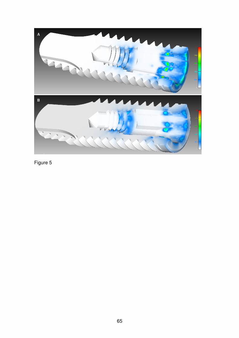
65
Figure 5
A
B

66
CAPÍTULO 5
Carolina Guimarães Castro, Karla Zancopé, Rafael Calixto Salatti, Robson
Botolo da Silva, Elington Rodrigues, Flávio Domingues das Neves. Integrity of
Morse taper Implants after fatigue vertical and off-center load. Clinical Oral
Implants Research.

67
Abstract
Objective: The aim of the present study was to evaluate the integrity of Morse
taper implant assembled with 2 pieces abutment after fatigue test, regarding
deformation and microleakage.
Material and methods: 19 Morse taper implants were specific manufactured with
an internal channel for the present study. The implants were divided in 5 groups
according the methodology of evaluation and the step of fatigue test: 3D
measurements, optical microscopy and microleakage. Three groups were
submitted to 1 million dynamic cycles under 116N vertical and off-center load.
Results: All samples submitted to dynamic fatigue achieved the end of the 1
million cycles with no failure. The 3D measurements of group A samples
showed no change in the evaluated dimensions, for both analysis: assembled
and disassembled. For microleakage test, in the 80 minutes reading leak was
observed in 1 sample from group B (with fatigue) and in 3 samples of group D.
The microscopy analysis demonstrated no deformation in the tapered portion of
the implants, confirming the 3D measurements results and the absence of
failure after fatigue tests.
Conclusion: In the present study, 1 million fatigue cycles with load applied in
vertical direction off-center of implant had no negative influence in the integrity
of Morse taper implant with 2 pieces abutment assembly.
Introduction
One hundred and fifty years ago, in 1864, the Morse Taper concept was
defined by Stephen A. Morse, an enterprising mechanic, who developed it to
reliably join two rotating machine components (Hernigou et al., 2013). More
than 25 years ago, the Morse taper principle was applied in oral implantology
(Moser, Nentwig, 1989). When compared to hexagonal prosthetic interfaces,
the tapered junction of Morse taper results in an excellent mechanical stability
large contact pressure and resulting frictional resistance between the implant
and the abutment (Albrektsson, 1988; Cochran, 1996; Bozkaya & Müftü, 2003).
As the hexagonal configurations depend totally on the screw abutment
pre-load to maintain the stability between implant and abutment (Burguete et
al., 1994; Sakaguchi & Borgersen, 1995; Bozkaya & Müftü, 2003; Haack et al.,

68
1995; McGlumphy et al., 1998), the masticatory axial loading could results in
the abutment screw loosening (Schwarz, 2000). To tapered interface, form lock
and friction are the basic principles to a secure and effective connection (Merz
et al., 2000; Bozkaya & Müftü, 2003).
Morse taper system avoids micromoviments in the implant/abutment (I/A)
interface contributing to a minimum inflammation level in the adjacent tissue
(Dibart et al., 2005) and to a less crestal-bone loss adjacent to implant (King et
al., 2002; Hansson 2003). To optimize the prosthetic indexation, such a keying
device, an implant company added an internal geometric index mid-level of the
cone of the implant body (Perriard et al., 2002). After a comparison regarding
the mechanical strength between the Morse taper systems, with and without the
internal index, Perriard et al. (2002) observed no difference between the
standard cone and the newly designed internally keyed design. Still under
mechanical scenario, a clinical study evaluating 2549 Morse taper implants after
6 years under loading concluded that the high mechanical stability of tapered
connection is the responsible for the significant reduction of prosthetic failures
or complications (Mangano et al., 2011).
Although the high survival rate of Morse taper implants, a lot of questions
still motivate scientific researches. Among them, could be cited if is there
abutment displacement into the implant over time and could this displacement
put in risk the stability of tapered connection? The understanding of basic
mechanical principles allows guide the understanding of mechanical behavior of
dental implants submitted to different load conditions. The association of
methodologies provides different points of view of the same mechanical
occurrence.
The aim of the present study was to evaluate the integrity of Morse taper
implant assembled with 2 pieces abutment after fatigue test, regarding
deformation and microleakage. The null hypothesis is that 1 million fatigue
cycles with load applied in vertical direction off-center of implant has no
influence in the implant/abutment integrity.
Material and Methods
Nineteen Morse taper implants (Titamax Morse taper Implant
4.0x13.0mm code: 109.620, Neodent, Brazil) were specific prepared for the

69
present study. The samples were manufactured with a channel from the apical
to the base of the screw chamber within the implant (Figure 1). The samples
were divided in 5 groups, according the methodologies that them were
submitted (Figure 2).
Figure 1 – Implant with hole assembled to abutment.
Figure 2 – Division of the groups, according to different methodologies.
As described in Figure 2, 5 (group A) of the 19 implants were submitted
to tridimensional measurements (Optiv 222, Hexagon, Germany) regarding the
external and internal diameters of implant and the internal taper angle. After
these first measurements, all implants were inserted in polymer with a hole,
maintaining 3mm of cervical region of implant exposed, according to ISO
14801. After, the implants were assembled to 2 pieces Morse taper abutments
(Universal Abutment CM Exact, 4.5x4.0x2.5mm, Neodent) with 15Ncm insertion
torque, as recommended by manufacturer (Figure 3).

70
Figure 3 – Abutment assembled to implant with 15Ncm insertion torque.
After assembly, the samples of group A were submitted to tridimensional
measurements regarding the external implant diameter in the cervical portion
and the height between the abutment and implant platform.
Twelve samples (including the 5 samples of group A) were submitted to
dynamic fatigue according the set up published by Perriard et al., 2002. The
samples were inclined by 15° off the vertical and a T-shaped bar was positioned
over the abutment and the loading was applied in a vertical direction at 5mm
off-implant center onto one end of the horizontal bar (Figure 4). The samples
were submitted to 1 million cycles under a load of 116N and 15Hz frequency in
Instron model E3000 machine (Instron, United Kingdon). During the test the
minimum force was 10% of maximum load, 11.6N.
Figure 4 – Fatigue testing set up.
The 12 samples submitted to fatigue test were allocated in the groups A,
B and C, according to Figure 2. The samples of group A (5 samples) were
submitted to tridimensional measurements before and after disassembly

71
between abutment and implant. The samples of groups B and D (4 samples
each group) were submitted to microleakage evaluation. The samples of groups
C and E (3 samples each group) were analyzed by optical microscopy.
The microleakage test was performed based on methodology described
by Gross et al., 1999. The interface between the cervical of implant and the
polymer was sealed with silicon, and a polymer was assembled into the
abutment, both to avoid the leakage for these ways. Each sample was
positioned in a poliacetal tube assembled to a system designed to introduce
controlled air pressure to 8 tubes. The samples were suspended in water and
0.3ml of gentian violet (Farmax, Brazil) was inserted into the polymer tube
where the implant was assembled (Figure 5). After, a constant air pressure of 2
Bars was achieved and the readings were taken at intervals of 5, 20 and 80
minutes from the time of initial pressure activation.
Figure 5 – Microleakage testing set up.
For microscopy analysis, the samples from groups C and E (3 samples
for each group) were embedded in resin (CitoPress1, Struers, USA), sanded
(TegraSystem, Struers) and evaluated in optic microscope (AxionVision Imager
A1m, Zeiss, Germany).
Results
All samples submitted to dynamic fatigue achieved the end of the 1
million cycles with no failure.
The 3D measurements of group A samples showed no change in the
evaluated dimensions, for both analysis: assembled and disassembled. The

72
media value for height between the abutment and implant platform was 6.32
mm before and after fatigue test.
For microleakage test, in the 5 minutes reading, gentian violet leak was
observed in 2 samples from group D (without fatigue). In the 80 minutes reading
leak was observed in 1 sample from group B (with fatigue) and in 3 samples of
group D.
Figure 6 – 80 minutes reading during the microleakage test. It was observed
gentian violet leak in the samples 09 (from group B), 13, 15 and 16 (from group
D).
The microscopy analysis demonstrated no deformation in the tapered
portion of the implants, confirming the 3D measurements results and the
absence of failure after fatigue tests.
Figure 7 – Microscopy analysis of group E samples.

73
Figure 8 – Microscopy analysis of group C samples.
Discussion
The null hypothesis was rejected, since there were different gentian violet
leak readings during the microleakage test between the groups.
To investigate specimen resistance to fatigue during approximately 3
years of simulated function, a target of 1 million cycles was defined (Kraisat et
al., 2002). The loading frequency of the tests was 15 Hz. The load ranged
sinusoidally between a nominal peak value and 10% of this value (in
accordance with ISO 14801). The load, 116 N, was calculated according to
equation F=M/d sinα where F is force applied, M is torque applied during
abutment tightening, d is lever length and α is the inclination of the specimen.
For M=15Ncm, d=5mm and α=15°. This arrangement thus generated both a
bending and a torqueing moment on the conical joints (Perriard et al., 2002). All
the samples submitted to 1 million cycles achieved the end of the tests without
failure.
The fatigue test had influence just on microleakage evaluation. After 80
minutes of test under 2 Bars pressure, the group submitted to fatigue (B)
presented just one sample (25% of all samples) with gentian violet leaking,
while the without fatigue test group (D) presented 3 samples (75%) with gentian

74
violet leaking. This means that the fatigue test, even with off-center load, seams
to increase the lock and friction between the implant and the abutment.
In other study (Çehreli et al., 2004) this event of higher lock between
implant and abutment was already observed since, after fatigue test, the Morse
taper abutments had signs of slight wear on the morse-taper part, but not on the
screw threads, which implies that the morse-taper indisputably carried most of
the applied load and protected the abutment threads from overloading. The
mechanical principles of taper connection were well discussed by previous
studies (Merz et al., 2000; Bozkaya & Müftü, 2003) discussing the large contact
pressure and resulting frictional resistance. In summary, in the case of taper
Morse junction, the biting force acts in the direction of the abutment insertion,
hence aids to secure the connection. This situation is in direct contrast to
implants using screws where the biting force lowers the pretension in the screw
(Bozkaya & Müftü, 2003). Although the apparent higher interface lock for group
after fatigue, through the 3D measurements no change of height between the
abutment and implant platform was noted.
In all implant systems, the implant-abutment mating design determines
the mechanical integrity of the implant-abutment complex and rules joint
strength and stability (Norton 1997; Binon 2000; Merz et al. 2000; Norton 2000;
Khraisat et al.2002; Akça et al. 2003; Steinebrunner et al., 2008). Together with
proper design of the occlusion and stable osseointegration, a reliable
connection between implant and abutment is an important precondition for the
appropriate functioning and stability of implant restorations (Norton, 1997).
In the present study, 1 million fatigue cycles with load applied in vertical
direction off-center of implant had no negative influence in the integrity of Morse
taper implant/2 pieces abutment assembly. While mechanical testing merely
shows if and where a system will break, the non-destructive methods provide
insight into the inherent mechanics of a given technical system. Another non-
destructive method could be used in future studies to obtain meaningful results,
such a non-linear Finite Element Method model.
Acknowledgements
The authors want to thank Neodent (Curitiba, Brazil) for its contribution to
this research.

75
References
Akça, K., Çehreli, M.C. & Iplikçioglu, H. (2003) Evaluation of the mechanical
characteristics of the implant–abutment complex of a reduced-diameter morse
taper implant: a nonlinear finite element stress analysis. Clinical Oral Implants
Research 14: 444–455.
Albrektsson, T. (1988) A multicenter report on osseointegrated oral implants.
Journal of Prosthetic Dentistry 60: 75-84.
ASTM E407-07 - Standard Practice for Microetching Metals and Alloys
Binon, P. (2000) Implants and components. International Journal of Oral &
Maxillofacial Implants 15: 76–94.
Bozkaya, D. & Müftü, S. (2003) Mechanics of the tapered interference fit in
dental implants. Journal of Biomechanics 36: 1649-1658.
Burguete, R.L., Johns, R.B., King, T. & Patterson E.A. (1994) Tightening
characteristics for screwed joints in osseointegrated dental implants. Journal of
Prosthetic Dentistry 71: 592-599.
Çehreli M.C., Akça, K., Iplikçioglu, H. & Sahin, S. (2004) Dynamic fatigue
resistance of implant–abutment junction in an internally notched morse-taper
oral implant: influence of abutment design. Clinical Oral Implant Research 15:
459–465.
Cochran, D. (1996) Review: Implant I. In: Annals of Periodontology. Vol 1: 1996
World Workshop in Periodontics. Chicago: American Academy of
Periodontology.
Dibart. S., Warbington, M., Su, M.F. & Skobe, Z. (2005) In vitro evaluation of the
implant-abutment bacterial seal: the locking taper system. International Journal
of Oral Maxillofacial Implants 20: 732-737.
Gross, M., Abramovich, I. & Weiss, E.I. (1999) Microleakage at the abutment-
implant interface of osseointegrated implants: a comparative study. International
Journal of Oral Maxillofacial Implants 14:94-100.
Haack, J.E., Sakaguchi, R.L., Sun, T. & Coffey, J.P. (1995) Elongation and
preload stress in dental implant abutment screws. International Journal of Oral
Maxillofacial Implants 10: 529-536.
Hansson, S. (2003) A conical implant-abutment interface at the level of the
marginal bone improves the distribution of stresses in the supporting bone. An

76
axisymmetric finite element analysis. Clinical Oral Implants Research 14: 286-
293.
Hernigou, P., Queinnec, S. & Flouzat Lachaniette, C.H. (2013) One hundred
and fifty years of history of the Morse taper: from Stephen A. Morse in 1864 to
complications related to modularity in hip arthroplasty. International
Orthopaedics 37: 2081-2088.
ISO 14801:2007 - Dynamic fatigue test for endosseous dental implants
Khraisat, A., Stegaroiu, R., Nomura, S. & Miyakawa, O. (2002) Fatigue
resistance of two implant/abutment joint designs. Journal of Prosthetic Dentistry
88: 604-610.
King, G.N., Hermann, J.S., Schoolfield, J.D., Buser, D. & Cochran, D.L. (2002)
Influence of the size of the microgap on crestal bone levels in non-submerged
dental implants: a radiographic study in the canine mandible. Journal of
Periodontology 73: 1111-1117.
Mangano, C., Mangano, F., Shibli, J.A., Tettamanti, L., Figliuzzi, M., d'Avila, S.,
Sammons, R.L. & Piattelli, A. (2011) Prospective evaluation of 2,549 Morse
taper connection implants: 1- to 6-year data. Journal of Periodontology 82: 52-
61.
McGlumphy, E.A., Mendel, D.A. & Holloway, J.A. (1998) Implant screw
mechanics. Dental Clinics of North America 42:71-89.
Merz, B.R., Hunenbart, S. & Belser, U.C. (2000) Mechanics of the implant-
abutment connection: an 8-degree taper compared to a butt joint connection.
International Journal of Oral Maxillofacial Implants 15: 519-526.
Moser, W. & Nentwig, G.H. (1989) Finite-Element-Studien zur Optimierung von
Implantatgewindeformen Implantatgewindeformen. Z Zahnärztl Implantol 5: 29–
32.
Norton, M.R. (1997) An in vitro evaluation of the strength of an internal conical
interface compared to a butt joint design. Clinical Oral Implants Research 8:
290–298.
Norton, M.R. (2000) In vitro evaluation of the strength of the conical implant-to-
abutment joint in two commercially available implant systems. Journal of
Prosthetic Dentistry 83: 567-571.
Perriard, J., Wiskott, W.A., Mellal, A., Scherrer, S.S., Botsis, J. & Belser, U.C.
(2002) Fatigue resistance of ITI implant-abutment connectors -- a comparison of

77
the standard cone with a novel internally keyed design. Clinical Oral Implants
Research 13: 542-549.
Sakaguchi, R.L. & Borgersen, S.E. (1995) Nonlinear contact analysis of preload
in dental implant screws. International Journal of Oral Maxillofacial Implants 10:
295-302.
Schwarz, M.S. (2000) Mechanical complications of dental implants. Clinical Oral
Implants Research 11 Suppl 1: 156-8.
Steinebrunner, L., Wolfart, S., Ludwig, K. & Kern, M. (2008) Implant-abutment
interface design affects fatigue and fracture strength of implants. Clinical Oral
Implants Research 19: 1276-1284.

78
3- CONSIDERAÇÕES FINAIS
Na Implantodontia moderna, para se definir sucesso em Implantodontia,
pensa-se em estabilidade mecânica pilar/implante, estabilidade biológica dos
tecidos adjacentes, estabilidade mecânica da prótese, integridade do implante
e ausência de outras complicações técnicas. No entanto, frente às diferentes
interfaces protéticas que se tem atualmente, deve-se esperar diferentes
padrões e motivos de falhas. É sabido que a alta estabilidade da conexão cone
Morse significativamente reduz a taxa de complicações protéticas. Em
acompanhamento clínico de 2549 implantes cone Morse, entre 1 e 6 anos em
função mastigatória, observou-se 0,37% de perda do componente protético
(Mangano et al., 2011). Sistemas de implantes que dependem da pré-carga do
parafuso para manter o abutment em posição parecem estar mais expostos a
complicações protéticas, uma vez que forças resultantes de contatos oclusais
(fisiológicas ou patológicas) podem exceder a força de união do componente
ao implante e resultar na soltura ou fratura do parafuso, e, comsequentemente,
do sistema (Merz et al., 2000; Steinebrunner et al., 2008).
As características da interface componente protético/implante
influenciam não apenas o comportamento mecânico do sistema, mas também
a resposta biológica adjacente ao implante. A estabilidade da interface, assim
como a menor amplitude de micromovimentos, tem sido pontuada como
responsável por favorecer a distribuição de tensões no osso (Hansson, 2003) e
por diminuir a reabsorção da crista óssea periimplantar (King et al., 2002;
Mangano et al., 2011).
Por ser uma interface cônica, parece que o carregamento mastigatório
pode até resultar em maior embricamento entre o componente protético e o
implant cone Morse. No presente estudo, observou-se menor microinfiltração
em sistemas submetidos a fadiga e em estudo prévio, o evento de maior fricção
entre as partes também foi notado por meio de sinais ao longo da porção
cônica do componente (Çehreli et al., 2004).
Considerando que o cone interno do implante é o mesmo para os
diferentes diâmetros de implante e as diferentes direções de carga que existem
na cavidade oral, deve-se ponderar a seleção do diâmetro do implante para
reabilitação de diferentes regiões da boca. No presente estudo, pôde-se notar

79
que sob carregamento axial, o diâmetro do implante é mandatório no nível de
deformação horizontal que ocorre na região cervical. Nesse contexto, implantes
com maior diâmetro externo e, consequentemente, maior parede de titânio ao
redor do cone interno do implante, apresentam menor deformação e devem ser
considerados para reabilitações unitárias em regiões posteriores, em caso de
disponibilidade óssea.
Com o objetivo de buscar vantagens protéticas, algumas empresas
propuseram a inclusão de indexador interno no implante cone Morse. Neste
estudo, também avaliou-se se a inclusão do index poderia afetar o vedamento
e a resistência do implante, uma vez que resulta na diminuição da área de
contato na porção cônica implante/componente. A partir das metodologias de
microinfiltração bacteriana e de resistência a fratura, observou-se que a
presença do index não comprometeu o desempenho de implantes cone Morse.
Estudos futuros associando metodologias não destrutivas que permitam
a predição da falha em implantes cone Morse podem cada vez mais refinar a
indicação deste sistema que já tem uma taxa clínica de sucesso tão
consolidada. O método de elementos finitos é uma das ferramentas que pode
ser considerada para tais avaliações. No entanto, como é uma ferramenta
totalmente alimentada pelo pesquisador no que tange a inclusão de
propriedades mecânicas assim como a definição das condições de contato
entre as peças, a simulação em elementos finitos do sistema cone Morse deve
considerar o seu princípio mecânico de fricção na interface cônica e,
consequente, proteção das roscas do parafuso do componente protético
durante a distribuição de tensões (Merz et al., 2000). Muito tem-se que evoluir
sobre a simulação de elementos finitos para implantes cone Morse, buscando a
fidelidade com o que ocorre na prática. Um dos capítulos deste estudo buscou
apresentar duas opções, com suas respectivas limitações, para a simulação
correta da pré-carga em sistema cone Morse, considerando que a pré-carga
nestes sistemas não fica restrita ao parafuso, como acontece em sistemas de
implante hexagonais externos.
Como sugestões de estudos futuros, pode-se propor o aprofundamento
em outras características da metodologia de elementos finitos aplicada ao
sistema cone Morse, assim como acompanhamentos clínicos retrospectivos
que demonstrem o resultado biológico da estabilidade mecânica deste sistema.

80
4- CONCLUSÕES
De acordo com os resultados obtidos nos estudos laboratoriais, pode-se
concluir que:
1- O diâmetro influenciou a deformação nas paredes externa e interna na
região cervical de implantes cone Morse;
2- A presença de indexador protético no fim do cone interno de implantes
cone Morse não teve influência na infiltração bacteriana sob
carregamento estático;
3- A presenção de indexador protético no fim do cone interno de implante
cone Morse não reduziu a sua resistência à fratura;
4- Na simulação de pré-carga em implantes cone Morse não foi encontrada
nenhuma diferença na distribuição das tensões ao longo da junção
implante/ pilar, para ambos os métodos para simular essa condição;
5- Um milhão de ciclos de fadiga com carga aplicada axialmente fora do
longo eixo do implante não influenciou negativamente a integridade de
implante cone Morse montado com componente protético de parafuso
passante.
Recommended


![Dissertação de Mestrado - UFF - Niterói · carregamento axial cíclico [2]. Essas estruturas sob tal combinação de carregamentos apresentam um aumento crescente da deformação](https://img.dokumen.tips/doc/110x75/5c60b21a09d3f21b6a8be4bb/dissertacao-de-mestrado-uff-niteroi-carregamento-axial-ciclico-2.jpg)
![¾Tipos de deformação viscosa viscoelástica - feis.unesp.br · Deformação nos materiais cristalinos [9] 1> ¾Deformação s.f. alteração, modificação da forma, desvio da](https://img.dokumen.tips/doc/110x75/5bd7ca0109d3f2404d8b512c/tipos-de-deformacao-viscosa-viscoelastica-feisunespbr-deformacao.jpg)