Texas Instruments Inc., 2015 1
C28x Digital Power Library
v3.5
Mar-15
Module User’s Guide
C28x Foundation Software
Texas Instruments Inc., 2015 2
IMPORTANT NOTICE
Texas Instruments and its subsidiaries (TI) reserve the right to make changes to their products or to discontinue any product or service without notice, and advise customers to obtain the latest version of relevant information to verify, before placing orders, that information being relied on is current and complete. All products are sold subject to the terms and conditions of sale supplied at the time of order acknowledgement, including those pertaining to warranty, patent infringement, and limitation of liability. TI warrants performance of its semiconductor products to the specifications applicable at the time of sale in accordance with TI’s standard warranty. Testing and other quality control techniques are utilized to the extent TI deems necessary to support this warranty. Specific testing of all parameters of each device is not necessarily performed, except those mandated by government requirements. Customers are responsible for their applications using TI components. In order to minimize risks associated with the customer’s applications, adequate design and operating safeguards must be provided by the customer to minimize inherent or procedural hazards.
TI assumes no liability for applications assistance or customer product design. TI does not warrant or represent that any license, either express or implied, is granted under any patent right, copyright, mask work right, or other intellectual property right of TI covering or relating to any combination, machine, or process in which such products or services might be or are used. TI’s publication of information regarding any third party’s products or services does not constitute TI’s approval, license, warranty or endorsement thereof. Reproduction of information in TI data books or data sheets is permissible only if reproduction is without alteration and is accompanied by all associated warranties, conditions, limitations and notices. Representation or reproduction of this information with alteration voids all warranties provided for an associated TI product or service, is an unfair and deceptive business practice, and TI is not responsible or liable for any such use. Resale of TI’s products or services with statements different from or beyond the parameters stated by TI for that products or service voids all express and any implied warranties for the associated TI product or service, is an unfair and deceptive business practice, and TI is not responsible nor liable for any such use. Also see: Standard Terms and Conditions of Sale for Semiconductor Products. www.ti.com/sc/docs/stdterms.htm
Mailing Address: Texas Instruments Post Office Box 655303 Dallas, Texas 75265
Copyright 2015, Texas Instruments Incorporated

Texas Instruments Inc., 2015 3
Trademarks TMS320 is the trademark of Texas Instruments Incorporated. All other trademarks mentioned herein are property of their respective companies
Acronyms DPLib: Digital Power library functions. C28x: Refers to devices with the C28x CPU core. IQmath: Fixed-point mathematical functions in C. Q-math: Fixed point numeric format defining the binary resolution in bits.
Texas Instruments Inc., 2015 4
Contents Chapter 1. Introduction .................................................................................... 6
1.1. Introduction ..................................................................................................................... 6
Chapter 2. Installing the DP Library ................................................................ 8
2.1. DP Library Package Contents ....................................................................................... 8
2.2. How to Install the Digital Power Library ..................................................................... 8
2.3. Naming Convention ........................................................................................................ 8
Chapter 3. Using the Digital Power Library .................................................. 10
3.1. Library Description and Overview ............................................................................. 10
3.2. Steps to use the DP library ........................................................................................... 12
3.3. Viewing DP library variables in watch window ......................................................... 14
3.4. IQ Math & IQ Math Library Usage............................................................................ 15
Chapter 4. Module Summary ......................................................................... 16
4.1. DP Library Function Summary................................................................................... 16
Chapter 5. C28x Module Descriptions .......................................................... 18
5.1. Controllers ..................................................................................................................... 18 5.1.1 CNTL_2P2Z : Two Pole Two Zero Controller.......................................................... 18 5.1.2 CNTL_3P3Z : Three Pole Three Zero Controller .................................................... 23
5.2. Peripheral Configuration ............................................................................................. 28 5.2.1 ADC_SOC_Cnf : ADC Configuration ..................................................................... 28 5.2.2 PWM_PSFB_PCMC_Cnf : PWM for PCMC controlled PSFB Stage ...................... 30 5.2.3 PWM_1ch_UpCntDB_ActivHIC_Cnf : ..................................................................... 31
5.3. Peripheral Drivers ........................................................................................................ 32 5.3.1 ADCDRV_1ch : ADC Driver Single Channel ........................................................... 32 5.3.2 ADCDRV_4ch : ADC Driver Four Channel ............................................................. 35 5.3.3 ADCDRV_8ch : 8 channel ADC Driver .................................................................... 38 5.3.4 PWMDRV_1ch : PWM Driver Single Channel ........................................................ 42 5.3.5 PWMDRV_1chHiRes : PWM Driver Single Channel Hi Res ................................... 48 5.3.6 PWMDRV_1chHiResUpDwnCnt : PWM Driver 1ch Hi Res Up Down Count Mode 54 5.3.7 PWMDRV_PFC2PHIL : PWM Driver for Two Phase Interleaved PFC Stage ........ 59 5.3.8 PWMDRV_PSFB : PWM Driver for Phase Shifted Full Bridge Stage ..................... 63 5.3.9 PWMDRV_ComplPairDB : PWM Driver with complementary chA & chB PWM ..... 67 5.3.10 PWMDRV_DualUpDwnCnt : Dual PWM Driver , independent Duty on chA & ChB .......................................................................................................................................... 72 5.3.11 PWMDRV_BuckBoost : Dual PWM Driver, independent Duty on chA & chB ....... 76 5.3.12 PWMDRV_2ch_UpCnt : Dual PWM Driver, independent Duty on chA and chB .. 81 5.3.13 PWMDRV_1ch_UpDwnCnt : PWM Driver, Duty on chA centered at zero ........... 85 5.3.14 PWMDRV_1ch_UpDwnCntCompl : PWM Driver, Duty chA centered at period ... 89 5.3.15 PWMDRV_PSFB_VMC_SR : PWM Driver for VMC PSFB Stage with SR .......... 93 5.3.16 PWMDRV_LLC_ComplPairDB : PWMDriver for compl. PWM period modulation 97 5.3.17 PWMDRV_LLC_1ch_UpCntDB : PWM Driver for chA PWM edge shift, period mode ............................................................................................................................... 102 5.3.18 PWMDRV_LLC_1ch_upCntDB_Compl : Driver, chA PWM, edge shift period mode ........................................................................................................................................ 107
Texas Instruments Inc., 2015 5
5.3.19 DACDRV_RAMP : DAC Ramp Driver Interface .................................................. 113
5.4. Application Specific .................................................................................................... 117 5.4.1 PFC_ICMD : Current Command for Power Factor Correction .............................. 117 5.4.2 PFC_INVSQR : Inverse Square Math Block for Power Factor Correction ............ 120 5.4.3 PFC_BL_ICMD : Bridgeless PFC Current Command ........................................... 123 5.4.4 PFC_InvRmsSqr : Inverse of the RMS Squared ................................................... 127
5.5 Math Blocks ..................................................................................................................... 131 5.5.1 MATH_EMAVG : Exponential Moving Average .................................................... 131 5.5.2 SineAnalyzer : Sine Wave Analyzer ...................................................................... 135
5.6 Utilities ........................................................................................................................... 139 5.6.1 DLOG_4ch : Four Channel Data Logger ............................................................... 139 5.6.2 DLOG_1CH: Single Channel Datalogger .............................................................. 143
Chapter 6. Revision History ......................................................................... 146
Texas Instruments Inc., 2015 6
Chapter 1. Introduction
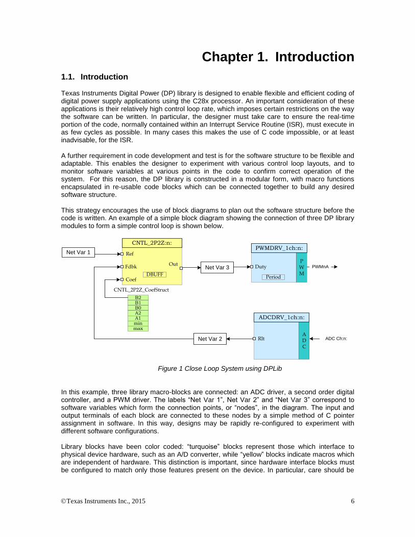
1.1. Introduction Texas Instruments Digital Power (DP) library is designed to enable flexible and efficient coding of digital power supply applications using the C28x processor. An important consideration of these applications is their relatively high control loop rate, which imposes certain restrictions on the way the software can be written. In particular, the designer must take care to ensure the real-time portion of the code, normally contained within an Interrupt Service Routine (ISR), must execute in as few cycles as possible. In many cases this makes the use of C code impossible, or at least inadvisable, for the ISR. A further requirement in code development and test is for the software structure to be flexible and adaptable. This enables the designer to experiment with various control loop layouts, and to monitor software variables at various points in the code to confirm correct operation of the system. For this reason, the DP library is constructed in a modular form, with macro functions encapsulated in re-usable code blocks which can be connected together to build any desired software structure. This strategy encourages the use of block diagrams to plan out the software structure before the code is written. An example of a simple block diagram showing the connection of three DP library modules to form a simple control loop is shown below.
Net Var 2
Net Var 3
Net Var 1
ADC Ch:n:ADC
ADCDRV_1ch:n:
Rlt
Out
Ref
Fdbk
CNTL_2P2Z:n:
Coef
B2B1B0A2A1minmax
CNTL_2P2Z_CoefStruct
DBUFF
PWM
PWMnA
PWMDRV_1ch:n:
Duty
Period
Figure 1 Close Loop System using DPLib In this example, three library macro-blocks are connected: an ADC driver, a second order digital controller, and a PWM driver. The labels “Net Var 1”, Net Var 2” and “Net Var 3” correspond to software variables which form the connection points, or “nodes”, in the diagram. The input and output terminals of each block are connected to these nodes by a simple method of C pointer assignment in software. In this way, designs may be rapidly re-configured to experiment with different software configurations. Library blocks have been color coded: “turquoise” blocks represent those which interface to physical device hardware, such as an A/D converter, while “yellow” blocks indicate macros which are independent of hardware. This distinction is important, since hardware interface blocks must be configured to match only those features present on the device. In particular, care should be

Texas Instruments Inc., 2015 7
taken to avoid creating blocks which access the same hardware (for example two blocks driving the same PWM output may well give undesirable results!). Both types of blocks require initialization prior to use, and must be configured by connecting their terminals to the desired net nodes. The initialization and configuration process is described in Chapter 3. Once the blocks have been initialized and connected, they can be executed by calling the appropriate code from an assembly ISR. Macro blocks execute sequentially, each block performing a precisely defined computation and delivering its’ result to the appropriate net list variables, before the next block begins execution.

Texas Instruments Inc., 2015 8
Chapter 2. Installing the DP Library
2.1. DP Library Package Contents The TI Digital Power library consists of the following components:
C initialization functions
Assembly macros files
An assembly file containing a macro initialization function and a real-time run functions.
An example CCS project showing the connection and use of DP library blocks.
Documentation
2.2. How to Install the Digital Power Library The DP library is distributed through the controlSUITE installer. The user must select the Digital Power Library Checkbox to install the library in the controlSUITE directory. By default, the installation places the library components in the following directory structure: <base> install directory is C:\ti\controlSUITE\libs\app_libs\digital_power\<device> …where <device> is the C28x platform. The following sub-directory structure is used: <base>\asm_macros Contains assembly runtime macros <base>\C_macros Contains C runtime macros <base>\CNF Peripheral initialization files <base>\doc Contains this file
<base>\include Contains the library header file for the “DPlib.h”
The installation also installs a template project using the DPLib for the device inside the controlSUITE directory controlSUITE\development_kits\TemplateProjects_<ver. No.>\
DPLibTemplate-<device_name> _<ver. No.> These template projects can be quickly modified to start a new project using the DPlib. NOTE: The digital power library for the F2806x only uses the fixed point instruction set and needs to be included in a project with the floating point turned off.
2.3. Naming Convention Each macro of the digital power library has an assembly file that contains the initialization and the run time code for the block. In addition to the assembly block peripheral interface blocks use a peripheral configuration function as well.

Texas Instruments Inc., 2015 9
An example of the naming convention used is shown below:
ADCDRV_1ch
Macro name
Describes the nature of
the macro function
Macro type
hardware driver = DRV
controller = CTL
generic utility = UTIL
application specific = PFC
Peripheral name
ADC, PWM, ...
(Not present in all macros)
Figure 2 – Function Naming Convention Include files, initialization functions, and execution macros share the same naming. In the above example, these would be…
Include file: ADCDRV_1ch.asm
Init function: ADCDRV_1ch_INIT n
Execution Macro: ADCDRV_1ch n
Where n refers to the instance number of the macro.
Note: In the case of some Peripheral Drivers (e.g. ADC Drivers and PWM drivers) the instance number also implies the Peripheral Number the DP Library macro would drive or use on the device. For example
ADCDRV_1ch 0 normalizes AdcResult0 of the ADC Peripheral &
PWMDRV_1ch 3 drives the EPWM3 peripheral present on the device.

Texas Instruments Inc., 2015 10
Chapter 3. Using the Digital Power Library
3.1. Library Description and Overview
Typical user software will consist of a main framework file written in C and a single Interrupt Service Routine (ISR) written in assembly. The C framework contains code to configure the device hardware and initialize the library macros. The ISR consists of a list of optimized macro modules which execute sequentially each time a hardware trigger event occurs. This structure of setting up an interrupt based program is common in embedded real-time systems which do not use a scheduler. For examples of device initialization code, refer to the peripheral header file examples for the C28x device. Conceptually, the process of setting up and using the DP library can be broken down into three parts.
1 Initialisation. Macro blocks are initialized from the C environment using a C callable function
(“DPL_Init()”) which is contained in the assembly file {ProjectName}-DPL-ISR.asm. This
function is prototyped in the library header file “DPlib.h” which must be included in the main C
file. 2 Configuration. C pointers of the macro block terminals are assigned to net nodes to form the desired control structure. Net nodes are 32-bit integer variables declared in the C framework. Note names of these net nodes are no dependent on the macro block.
3 Execution. Macro block code is executed in the assembly ISR (“DPL_ISR”). This function is
defined in the “{ProjectName}-DPL-ISR.asm” .
An example of this process and the relationship between the main C file and assembly ISR is shown below.

Texas Instruments Inc., 2015 11
main()
{
main.c
Device initialisation
while (1)
{
DPL_Init:
DPL_ISR:
DPL_ISR.asm
MACROn_INIT :n:
MACRO1 :n:
MACRO2 :n:
MACRO3 :n:
}
}
Net connections
Enable interrupts
Net-list declarations
#include “DPlib.h”
Macro initialisaton
2) Configuration:
Connect macro terminals
to net nodes
1) Initialisation:
Call macro
initialisation code
3) Execution:
Call ISR containing
macro blocks
#include “MACRO.asm”
Figure 3 : Relation between Main.c & ISR.asm file The DP library assembly code has a specific structure which has been designed to allow the user to freely specify the interconnection between blocks, while maintaining a high degree of code efficiency. Before any of the library macros can be called, they must be initialized using a short
assembly routine located in the relevant macro.asm file for each module. The code which calls
the macro initialization must reside in the same assembly file as the library ISR.
The assembly code in “DPL_Init” is C callable, and its’ prototype is in the library header file
“DPlib.h” described above. To initialize the macros, edit the DPL_Init section of the file
“{ProjectName}-DPL-ISR.asm” to add initialization calls for each macro required in the
application. The order of the calls is not important, providing one call is made for each macro-block required in the application. The respective macro assembly file must be included at the
starting of the “{ProjectName}-DPL-ISR.asm” file.
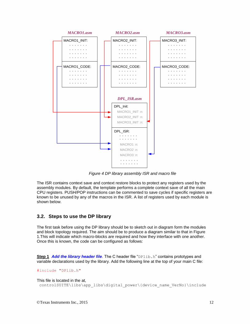
The internal layout and relationship between the ISR file and the various macro files is shown diagrammatically below. In this example, three DP library macros are being used. Each library
module is contained in an assembly include file (.asm extension) which contains both
initialization and macro code. The ISR file is also divided into two parts: one to initialize the macros, the other is the real-time ISR code in which the macro code is executed.
Texas Instruments Inc., 2015 12
MACRO1_INIT:
MACRO1_CODE:
MACRO2_INIT:
MACRO2_CODE:
MACRO3_INIT:
MACRO3_CODE:
MACRO1.asm MACRO2.asm MACRO3.asm
DPL_Init:
DPL_ISR:
DPL_ISR.asm
MACRO1_INIT :n:
MACRO2_INIT :n:
MACRO3_INIT :n:
MACRO1 :n:
MACRO2 :n:
MACRO3 :n:
Figure 4 DP library assembly ISR and macro file
The ISR contains context save and context restore blocks to protect any registers used by the assembly modules. By default, the template performs a complete context save of all the main CPU registers. PUSH/POP instructions can be commented to save cycles if specific registers are known to be unused by any of the macros in the ISR. A list of registers used by each module is shown below.
3.2. Steps to use the DP library The first task before using the DP library should be to sketch out in diagram form the modules and block topology required. The aim should be to produce a diagram similar to that in Figure 1.This will indicate which macro-blocks are required and how they interface with one another. Once this is known, the code can be configured as follows:
Step 1 Add the library header file. The C header file “DPlib.h” contains prototypes and
variable declarations used by the library. Add the following line at the top of your main C file: #include "DPlib.h"
This file is located in the at, controlSUITE\libs\app_libs\digital_power\{device_name_VerNo}\include

Texas Instruments Inc., 2015 13
This path needs to be added to the include path in the build options for the project.
Step 2 Declare terminal pointers in C. The “{ProjectName}-Main.c” file needs to be
edited to add extern declarations to all the macro terminal pointers which will be needed in the
application under the “DPLIB Net Terminals” section inside this file. In the example below,
three pointers to an instance of the 2P2Z control block are referenced. Please note the use of volatile keyword for the net pointers, as they point to net variables which are volatile as the ISR computes these values. // ---------------------------- DPLIB Net Pointers --------------------
-
// Declare net pointers that are used to connect the DP Lib Macros
here
// CNTL_2P2Z #instance 1 extern volatile long *CNTL_2P2Z_Ref1;
extern volatile long *CNTL_2P2Z_Fdbk1;
extern volatile long *CNTL_2P2Z_Out1;
extern volatile long *CNTL_2P2Z_Coef1;
Step 3 Declare signal net nodes/net variables in C. Edit the “{ProjectName}-Main.c “ C
file to define the net variables which will be needed in the application under the “DPLIB
Variables” section . In the example below, three arbitrarily named variables are declared as
global variables in C.
// ---------------------------- DPLIB Variables -----------------------
-
// Declare the net variables being used by the DP Lib Macro here volatile long Net1, Net2, Net3;
Step 4 Call the Peripheral configuration function. Call the peripheral configuration functions that are needed to configure the peripherals being used by the library macros being used in the system. Note as CNTL_2P2Z is a software block this step is not needed.
Step 5 Call the initialisation function from C. Call the initialization function from the C framework using the syntax below. /* Digital Power (DP) library initialization */
DPL_Init(); // initialize DP library
Step 6 Assign macro block terminals to net nodes. This step connects macro blocks together via net nodes to form the desired control structure. The process is one of pointer assignment using the net node variables and terminal pointers declared in the previous two steps. For example, to connect the ADC driver (instance 0) and 2P2Z control block (instance 1) to net node “Net2” as shown in Figure 1, the following assignment would be made:
// feedback node connections
ADCDRV_1ch_Rlt0 = &Net2;
CNTL_2P2Z_Fdbk1 = &Net2;

Texas Instruments Inc., 2015 14
Note that net pointer assignment can be dynamic: i.e. the user code can change the connection between modules at run-time if desired. This allows the user to construct flexible and complex control topologies which adapt intelligently to changing system conditions. Step 7 Add the ISR file. A single assembly file containing the ISR code and calls to the macro initialisation functions must exist in the project. The relationship between these elements is
described in Chapter 3.1. A blank template “ProjectName-DPL-ISR.asm” is included with the
DP library for this purpose in the template directory. To use this file, rename the file as
“{ProjectName}-DPL-ISR.asm” and add it to the project.
Step 8 Include the required macro header files. Add assembly include files to the top of the
ISR file “{ProjectName}-DPL_ISR.asm” as required. The include (.asm) file is required for
each block type being used in the project. For example, to use the 2P2Z controller block, add this line to the top of the ISR file: .include "CNTL_2P2Z.asm"
Step 9 Initialize required macro blocks. Edit the function “DPL_Init” in the above ISR file to
add calls to the initialization code in each macro file. Each call is invoked with a number to identify the unique instance of that macro block. For example, to create an instance of the 2P2Z control
block with the identifier “1”:
CNTL_2P2Z_INIT 1
Step 10 Edit the assembly ISR to execute the macros in the required order. Edit the function
“DPL_Run” to add calls to the run time routine of each macro and instance being used in the
system. In the example above the first instance of a 2P2Z control macro would be executed by: CNTL_2P2Z 1
Step 11 Add the DP library sections to the linker command file. The linker places DP library
code is a named sections as specified in the linker command file “{DeviceName-RAM/FLASH-
ProjectName}.CMD”. A sample CMD file is provided with the sections specified for the entire
DPS library in the template folder. The files only provides a sample memory allocation and can be edited by the user to suit their application. This DPLib Macros need to be placed in the data RAM. The sample linker file specifies where each memory section from each DP library module would be placed in internal memory. An example of section placement for the CNTL_2P2Z module is shown below.
/* CNTL_2P2Z section */
CNTL_2P2Z_Section : > dataRAM PAGE = 1
CNTL_2P2Z_InternalData : > dataRAM PAGE = 1
CNTL_2P2Z_Coef : > dataRAM PAGE = 1
Where dataRAM is a location in the RAM on the device which is specified in the sample CMD file.
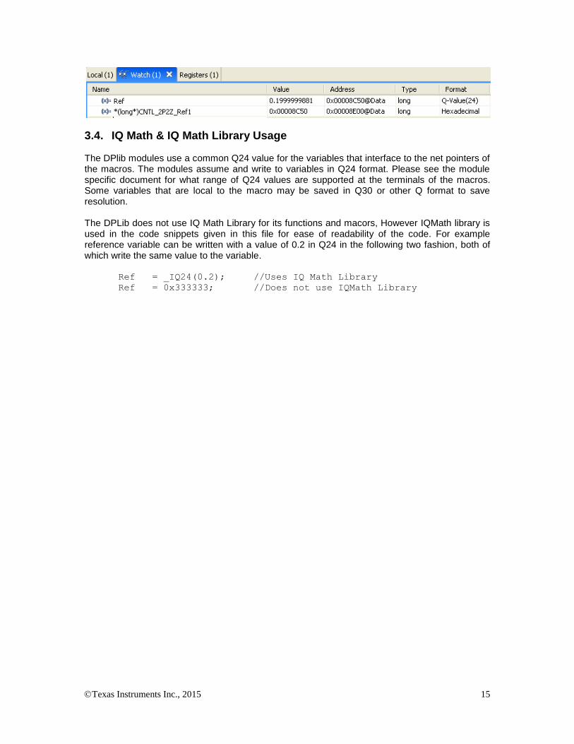
3.3. Viewing DP library variables in watch window
If is desired to see the DP library macro variables, i.e. the net pointers can be added to the watch window by adding a qualifier of *(type*). Shown below is the value stored in the net pointer Ref, and the net variable the pointer points to. Note the address of the net variable is stored in the net pointer.
Texas Instruments Inc., 2015 15
3.4. IQ Math & IQ Math Library Usage
The DPlib modules use a common Q24 value for the variables that interface to the net pointers of the macros. The modules assume and write to variables in Q24 format. Please see the module specific document for what range of Q24 values are supported at the terminals of the macros. Some variables that are local to the macro may be saved in Q30 or other Q format to save resolution. The DPLib does not use IQ Math Library for its functions and macors, However IQMath library is used in the code snippets given in this file for ease of readability of the code. For example reference variable can be written with a value of 0.2 in Q24 in the following two fashion, both of which write the same value to the variable.
Ref = _IQ24(0.2); //Uses IQ Math Library
Ref = 0x333333; //Does not use IQMath Library

Texas Instruments Inc., 2015 16
Chapter 4. Module Summary
4.1. DP Library Function Summary
The Digital Power Library consists modules than enable the user to implement digital control for different power topologies. The following table lists the modules existing in the power library and a summary of cycle counts and code size. Note: The memory sizes are given in 16-bit words and cycles are the system clock cycles taken to execute the Macro run file.
Module Name Module Type
Description HW Config File
Cycles
Init Code Size (W)
Run Code Size (W)
Data Size (W)
Multiple Instance Support
CNTL_2P2Z CNTL Second Order Control Law
NA 36 17 50 18 Yes
CNTL_3P3Z CNTL Third Order Control Law
NA 44 17 60 22 Yes
ADCDRV_1ch HW Single Channel ADC Driver
Yes 5 5 8 2 Yes
ADCDRV_4ch HW Four Channel ADC Driver
Yes 14 8 20 8 No
PWMDRV_1ch HW Single Channel PWM Driver
Yes 10 12 12 4 Yes
PWMDRV_1chHiRes HW Single Channel PWM Driver with Hi Res capability
Yes 10 12 12 4 Yes
PWMDRV_PFC2PhiL HW PWM driver for Two Phase Interleaved PFC stage
Yes 17 13 18 6 Yes
PWMDRV_PSFB HW PWM driver for Phase Shifted Full Bridge Power stage
Yes 21 13 21 6 Yes
PWMDRV_ComplPairDB HW PWM driver for complimentary pair PWMs
Yes 10 15 12 6 Yes
PWMDRV_DualUpDwnCnt HW
PWM driver with independent duty control on ch A and ch B, using up down count mode
Yes 14 13 16 6 Yes
PWMDRV_BuckBoost HW PWM driver for a four switch Buck Boost Stage
Yes 12 12 16 4 Yes
PWMDRV_2ch_UpCnt HW
PWM driver with independent duty control on ch A and ch B, using up down count mode
Yes 13 12 16 6 Yes
PWMDRV_1ch_ UpDwnCnt
HW Single channel driver with up down modulation
Yes 8 12 10 4 Yes

Texas Instruments Inc., 2015 17
PWMDRV_1ch_ UpDwnCntCompl
HW
Single channel driver with up down modulation centered around period
Yes 9 12 12 4 Yes
PWMDRV_PSFB_VMC_ SR
HW PWMDRV for PSFB PCMC with SR
Yes 35 8 36 6 Yes
PWMDRV_LLC_ ComplPairDB
Driver with Frequency Modulation
Yes 16 8 16 6 Yes
PWMDRV_LLC_1ch_ UpCntDB
HW
Driver with Frequency Modulation and Rising/Falling-edge adjustment via DB registers
Yes 19 7 24 6 Yes
PWMDRV_LLC_1ch_ UpCntDB_Compl
HW
Driver with Frequency Modulation and Rising/Falling-edge adjustment via DB registers
Yes 25 7 31 6 Yes
DACDRV_RAMP HW Driver to change DAC value for slope compensation
Yes 9 5 11 2 Yes
PFC_ICMD APPL Power Factor Correction Current Command Block
NA 17 9 19 10 Yes
PFC_INVSQR APPL Power Factor Correction Inverse Square Block
NA 71 15 39 12 Yes
PFC_BL_ICMD APPL Power Factor Correction Current Command Block
N/A 86 12 62 18 Yes
PFC_InvSqrRms APPL Power Factor Correction Inverse Square Block
N/A 66 10 36 10 Yes
MATH_EMAVG MATH Exponential moving average
NA 16 6 16 6 Yes
DLOG_4ch UTIL 4 channel Data Logger Module
NA 33 (Avg)
14 56 24 No
DLOG_1ch UTIL 1 channel Data Logger Module
NA 20 (Avg)
17 41 12 Yes
Texas Instruments Inc., 2015 18
Chapter 5. C28x Module Descriptions
5.1. Controllers
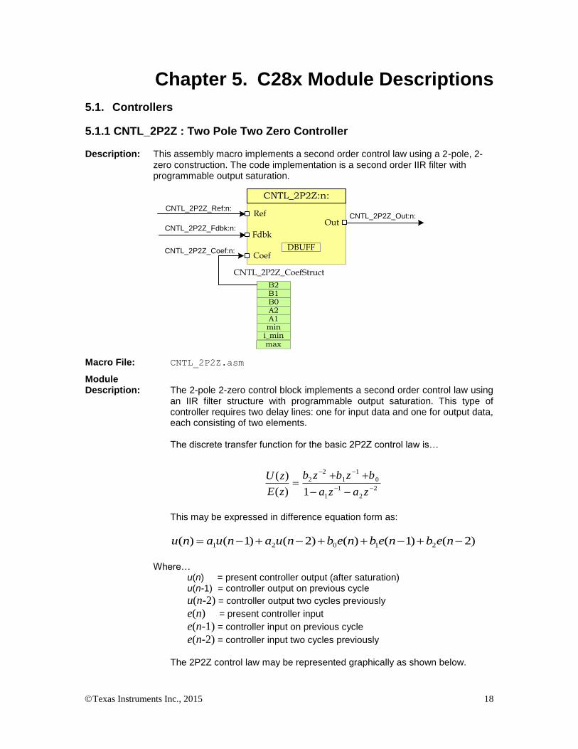
5.1.1 CNTL_2P2Z : Two Pole Two Zero Controller Description: This assembly macro implements a second order control law using a 2-pole, 2-
zero construction. The code implementation is a second order IIR filter with programmable output saturation.
CNTL_2P2Z_Out:n:CNTL_2P2Z_Ref:n:
CNTL_2P2Z_Fdbk:n:
CNTL_2P2Z_Coef:n:
OutRef
Fdbk
CNTL_2P2Z:n:
Coef
B2B1B0A2A1min
i_min
CNTL_2P2Z_CoefStruct
DBUFF
max
Macro File: CNTL_2P2Z.asm
Module Description: The 2-pole 2-zero control block implements a second order control law using
an IIR filter structure with programmable output saturation. This type of controller requires two delay lines: one for input data and one for output data, each consisting of two elements.
The discrete transfer function for the basic 2P2Z control law is…
2
2
1
1
0
1
1
2
2
1)(
)(
zaza
bzbzb
zE
zU
This may be expressed in difference equation form as:
)2()1()()2()1()( 21021 nebnebnebnuanuanu
Where…
u(n) = present controller output (after saturation) u(n-1) = controller output on previous cycle
u(n-2) = controller output two cycles previously
e(n) = present controller input
e(n-1) = controller input on previous cycle
e(n-2) = controller input two cycles previously
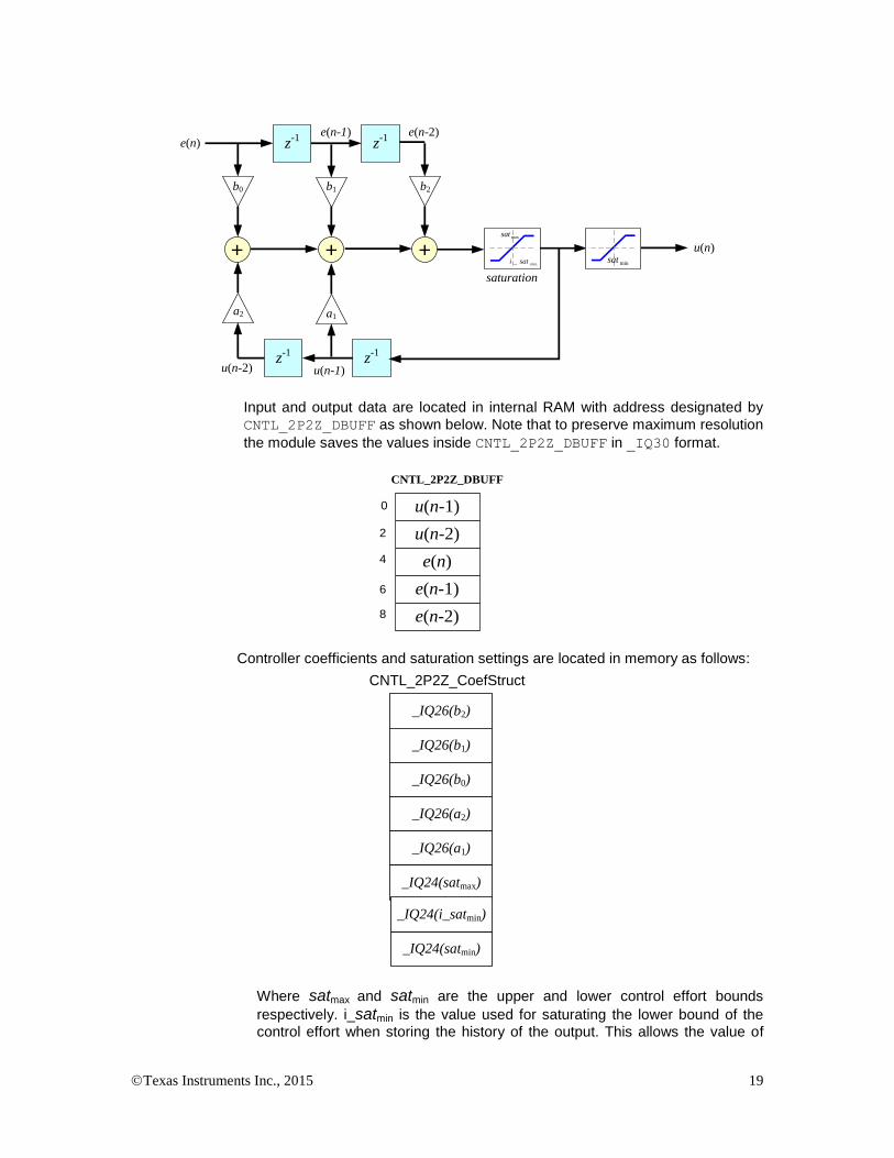
The 2P2Z control law may be represented graphically as shown below.
Texas Instruments Inc., 2015 19
z-1 z-1
+
z-1 z-1
++
e(n-2)e(n-1)e(n)
u(n)
u(n-2) u(n-1)
saturation
b2b1b0
a1a2
min_ sati
maxsat
minsat
Input and output data are located in internal RAM with address designated by
CNTL_2P2Z_DBUFF as shown below. Note that to preserve maximum resolution
the module saves the values inside CNTL_2P2Z_DBUFF in _IQ30 format.
u(n-1)
u(n-2)
e(n)
e(n-1)
e(n-2)
CNTL_2P2Z_DBUFF
0
2
4
6
8
Controller coefficients and saturation settings are located in memory as follows:
_IQ26(b2)
_IQ26(b1)
_IQ26(b0)
_IQ26(a2)
_IQ26(a1)
_IQ24(satmax)
_IQ24(satmin)
CNTL_2P2Z_CoefStruct
_IQ24(i_satmin)
Where satmax and satmin are the upper and lower control effort bounds
respectively. i_satmin is the value used for saturating the lower bound of the
control effort when storing the history of the output. This allows the value of
Texas Instruments Inc., 2015 20
the history have negative values which can help avoid oscillations on the output in case of no load. The user can specify it’s own value however it is recommended to use _IQ24(-0.9). Also, note that to preserve maximum resolution the coefficients are saved in Q26 format and the saturation limits are stored in Q24 format to match the output format.
Controller coefficients must be initialized before the controller is used. A
structure CNTL_2P2Z_CoefStruct is used to ensure that the coefficients
are stored exactly as shown in the table as the CNTL_2P2Z accesses them
relative to a base address pointer. The structure is defined in the library
header file DPlib.h to allow easy access to the elements from C.
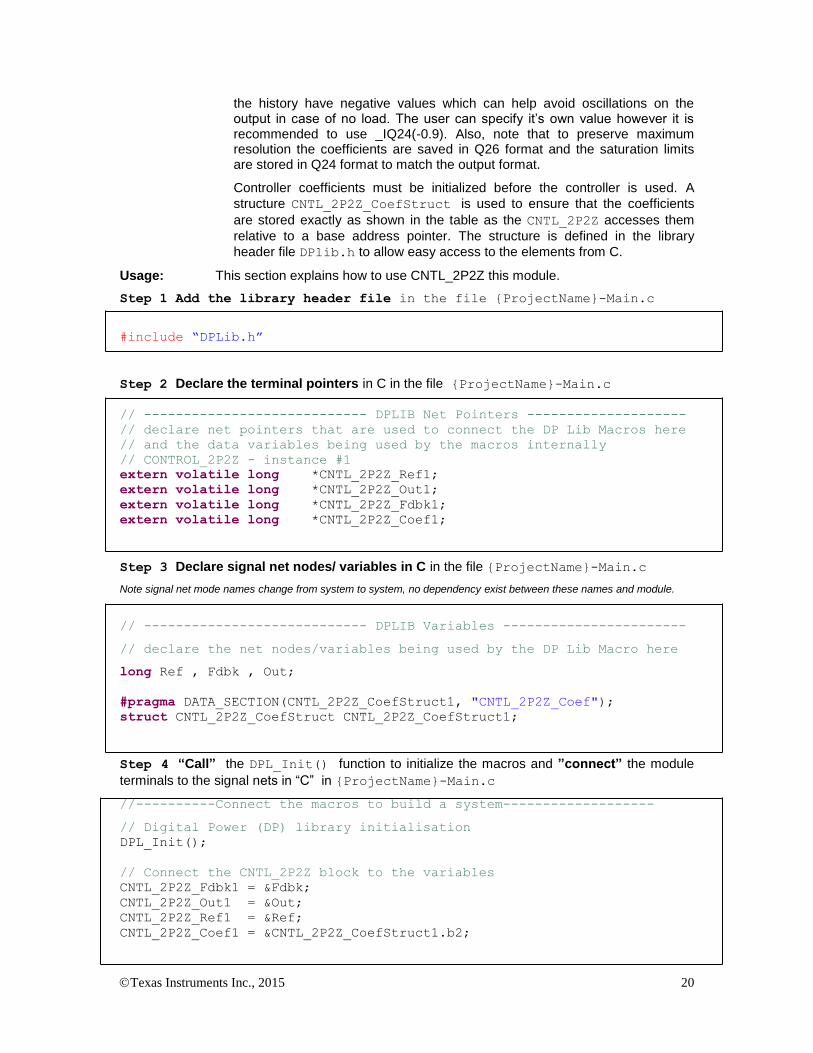
Usage: This section explains how to use CNTL_2P2Z this module.
Step 1 Add the library header file in the file {ProjectName}-Main.c
#include “DPLib.h”
Step 2 Declare the terminal pointers in C in the file {ProjectName}-Main.c
// ---------------------------- DPLIB Net Pointers --------------------
// declare net pointers that are used to connect the DP Lib Macros here
// and the data variables being used by the macros internally
// CONTROL_2P2Z - instance #1
extern volatile long *CNTL_2P2Z_Ref1;
extern volatile long *CNTL_2P2Z_Out1;
extern volatile long *CNTL_2P2Z_Fdbk1;
extern volatile long *CNTL_2P2Z_Coef1;
Step 3 Declare signal net nodes/ variables in C in the file {ProjectName}-Main.c
Note signal net mode names change from system to system, no dependency exist between these names and module.
// ---------------------------- DPLIB Variables -----------------------
// declare the net nodes/variables being used by the DP Lib Macro here
long Ref , Fdbk , Out;
#pragma DATA_SECTION(CNTL_2P2Z_CoefStruct1, "CNTL_2P2Z_Coef");
struct CNTL_2P2Z_CoefStruct CNTL_2P2Z_CoefStruct1;
Step 4 “Call” the DPL_Init() function to initialize the macros and ”connect” the module
terminals to the signal nets in “C” in {ProjectName}-Main.c
//----------Connect the macros to build a system-------------------
// Digital Power (DP) library initialisation
DPL_Init();
// Connect the CNTL_2P2Z block to the variables
CNTL_2P2Z_Fdbk1 = &Fdbk;
CNTL_2P2Z_Out1 = &Out;
CNTL_2P2Z_Ref1 = &Ref;
CNTL_2P2Z_Coef1 = &CNTL_2P2Z_CoefStruct1.b2;

Texas Instruments Inc., 2015 21
// Initialize the Controller Coefficients
CNTL_2P2Z_CoefStruct1.b2 = _IQ26(0.05);
CNTL_2P2Z_CoefStruct1.b1 = _IQ26(-0.20);
CNTL_2P2Z_CoefStruct1.b0 = _IQ26(0.20);
CNTL_2P2Z_CoefStruct1.a2 = _IQ26(0.0);
CNTL_2P2Z_CoefStruct1.a1 = _IQ26(1.0);
CNTL_2P2Z_CoefStruct1.max =_IQ24(0.7);
CNTL_2P2Z_CoefStruct1.i_min =_IQ24(-0.9);
CNTL_2P2Z_CoefStruct1.min =_IQ24(0.0);
//Initialize the net Variables/nodes
Ref=_IQ24(0.0);
Fdbk=_IQ24(0.0)
Out=_IQ24(0.0);
Step 5 Add the ISR assembly file “{ProjectName}-DPL-ISR.asm” to the project
Step 6 Include the assembly macro file in the {ProjectName}-DPL-ISR.asm
;Include files for the Power Library Macro's being used by the system
.include "CNTL_2P2Z.asm"
Step 7 Instantiate the INIT macro in assembly (this is one-time pass through code) inside the
C-callable DPL_Init() function which is defined in{ProjectName}-DPL-ISR.asm
;Macro Specific Initialization Functions
CNTL_2P2Z_INIT 1 ; CNTL_2P2Z Initialization
Step 8 Call the run time macro in assembly inside the C-callable function DPL_ISR()
which is the looped or ISR code. The function is defined in{ProjectName}-DPL-ISR.asm
;”Call” the Run macro
CNTL_2P2Z 1 ; Run the CNTL_2P2Z Macro
Step 9 Include the memory sections in {DeviceName}-{RAM/FLASH}-
{ProjectName}.CMD. Note, for the CNTL_2P2Z module the net pointers and the internal data
do not assume anything about allocation on a single data page.
/*CNTL_2P2Z sections*/
CNTL_2P2Z_Section : > dataRAM PAGE = 1
CNTL_2P2Z_InternalData : > dataRAM PAGE = 1
CNTL_2P2Z_Coef : > dataRAM PAGE = 1

Texas Instruments Inc., 2015 22
Module Net Definition:
Net Name (:n: is the instance number)
Description Format
Acceptable Range of Variable or of the Variable being pointed to
CNTL_2P2Z_Ref:n: Input Pointer Pointer to 32 bit fixed point input data location storing the Reference value for the controller.
Q24: [0, 1)
CNTL_2P2Z_Fdbk:n: Input Pointer Pointer to 32 bit fixed point input data location storing the Feedback value for the controller.
Q24: [0, 1)
CNTL_2P2Z_Coef:n: Input Pointer Pointer to the location where coefficient structure is stored.
See Module Description
CNTL_2P2Z_Out:n: Output Pointer
Pointer to 32 bit fixed point output location where the reference for the current loop is stored
Q24:[ 0,1)
CNTL_2P2Z_DBUFF:n: Internal Data
Data Variable storing the scaling factor See Module Description
Texas Instruments Inc., 2015 23
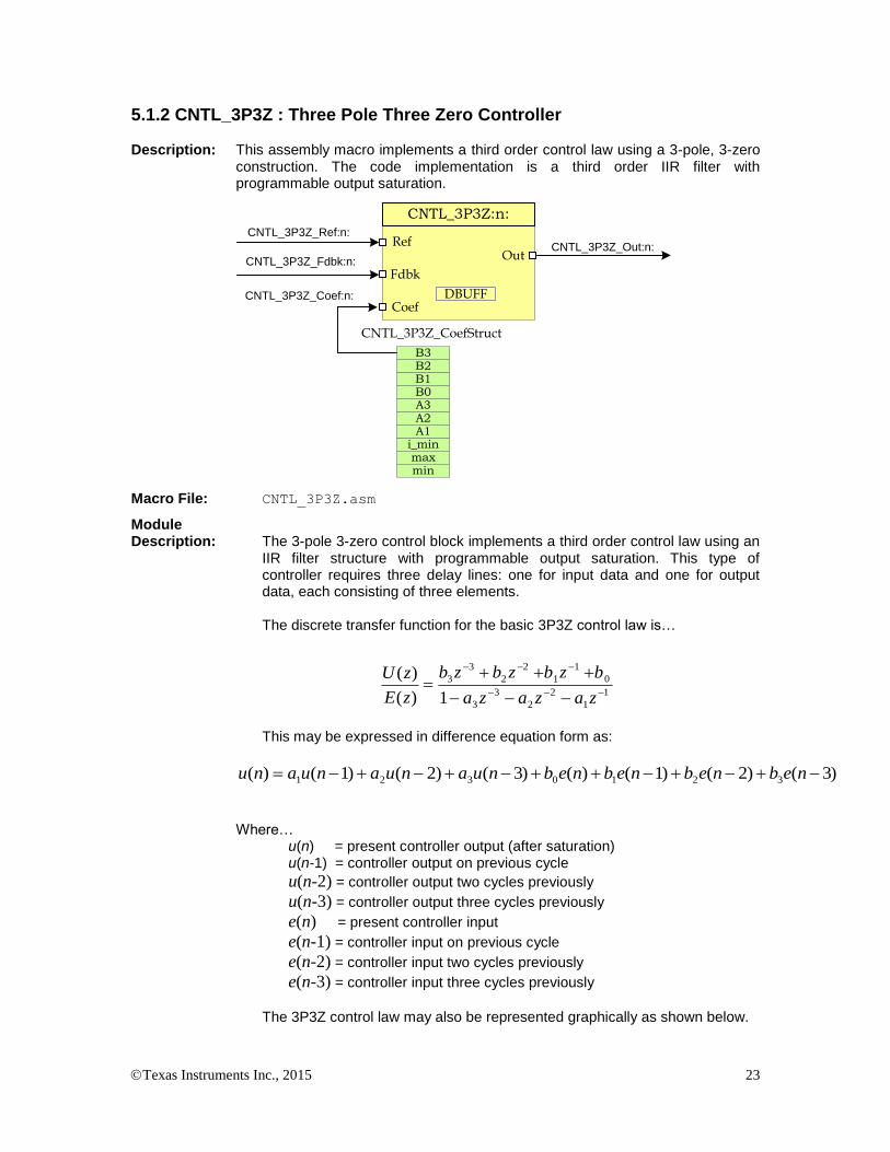
5.1.2 CNTL_3P3Z : Three Pole Three Zero Controller Description: This assembly macro implements a third order control law using a 3-pole, 3-zero
construction. The code implementation is a third order IIR filter with programmable output saturation.
OutRef
Fdbk
CNTL_3P3Z:n:
Coef
CNTL_3P3Z_CoefStruct
DBUFF
B2B1B0A3A2
i_minmax
B3
A1
CNTL_3P3Z_Ref:n:
CNTL_3P3Z_Fdbk:n:
CNTL_3P3Z_Out:n:
CNTL_3P3Z_Coef:n:
min
Macro File: CNTL_3P3Z.asm
Module Description: The 3-pole 3-zero control block implements a third order control law using an
IIR filter structure with programmable output saturation. This type of controller requires three delay lines: one for input data and one for output data, each consisting of three elements.
The discrete transfer function for the basic 3P3Z control law is…
1
1
2
2
3
3
0
1
1
2
2
3
3
1)(
)(
zazaza
bzbzbzb
zE
zU
This may be expressed in difference equation form as:
)3()2()1()()3()2()1()( 3210321 nebnebnebnebnuanuanuanu
Where… u(n) = present controller output (after saturation)
u(n-1) = controller output on previous cycle
u(n-2) = controller output two cycles previously
u(n-3) = controller output three cycles previously
e(n) = present controller input
e(n-1) = controller input on previous cycle
e(n-2) = controller input two cycles previously
e(n-3) = controller input three cycles previously
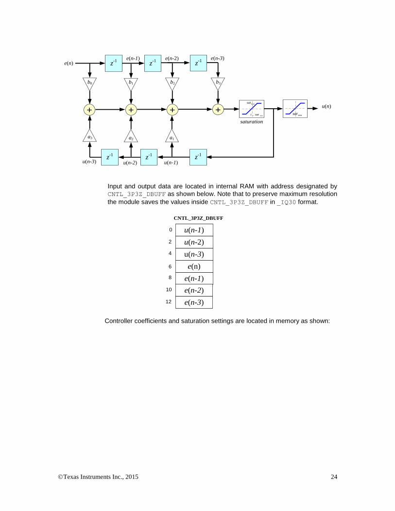
The 3P3Z control law may also be represented graphically as shown below.
Texas Instruments Inc., 2015 24
z-1 z-1
+
z-1 z-1
++
e(n-2)e(n-1)e(n)
u(n)
u(n-3) u(n-2)
b2b1b0
a2a3
z-1
+
e(n-3)
b3
z-1
u(n-1)
a1
saturation
min_ sati
maxsat
minsat
Input and output data are located in internal RAM with address designated by
CNTL_3P3Z_DBUFF as shown below. Note that to preserve maximum resolution
the module saves the values inside CNTL_3P3Z_DBUFF in _IQ30 format.
u(n-1)
u(n-2)
u(n-3)
e(n)
e(n-1)
CNTL_3P3Z_DBUFF
0
2
4
6
8
e(n-2)
e(n-3)
10
12
Controller coefficients and saturation settings are located in memory as shown:
Texas Instruments Inc., 2015 25
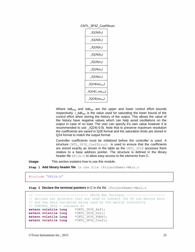
_IQ26(b3)
_IQ26(b2)
_IQ26(b1)
_IQ26(a3)
_IQ26(a2)
_IQ24(i_satmin)
_IQ24(satmin)
CNTL_3P3Z_CoefStruct
_IQ26(b0)
_IQ26(a1)
_IQ24(satmax)
Where satmax and satmin are the upper and lower control effort bounds
respectively. i_satmin is the value used for saturating the lower bound of the control effort when storing the history of the output. This allows the value of the history have negative values which can help avoid oscillations on the output in case of no load. The user can specify it’s own value however it is recommended to use _IQ24(-0.9). Note that to preserve maximum resolution the coefficients are saved in Q26 format and the saturation limits are stored in Q24 format to match the output format.
Controller coefficients must be initialized before the controller is used. A
structure CNTL_3P3Z_CoefStruct is used to ensure that the coefficients
are stored exactly as shown in the table as the CNTL_3P3Z accesses them
relative to a base address pointer. The structure is defined in the library
header file DPlib.h to allow easy access to the elements from C.
Usage: This section explains how to use this module.
Step 1 Add library header file in the file {ProjectName}-Main.c
#include “DPLib.h”
Step 2 Declare the terminal pointers in C in the file {ProjectName}-Main.c
// ---------------------------- DPLIB Net Pointers --------------------
// declare net pointers that are used to connect the DP Lib Macros here
// and the data variables being used by the macros internally
// CONTROL_3P3Z - instance #1
extern volatile long *CNTL_3P3Z_Ref1;
extern volatile long *CNTL_3P3Z_Out1;
extern volatile long *CNTL_3P3Z_Fdbk1;
extern volatile long *CNTL_3P3Z_Coef1;

Texas Instruments Inc., 2015 26
Step 3 Declare signal net nodes/ variables in C in the file {ProjectName}-Main.c
Note signal net mode names change from system to system, no dependency exist between these names and module.
// ---------------------------- DPLIB Variables -----------------------
// declare the net nodes/variables being used by the DP Lib Macro here
volatile long Ref , Fdbk , Out;
#pragma DATA_SECTION(CNTL_3P3Z_CoefStruct1, "CNTL_3P3Z_Coef");
struct CNTL_3P3Z_CoefStruct CNTL_3P3Z_CoefStruct1;
Step 4 “Call” the DPL_Init() to initialize the macros and ”connect” the module terminals
to the signal nets in “C” in {ProjectName}-Main.c
//----------Connect the macros to build a system-------------------
// Digital Power (DP) library initialisation
DPL_Init();
// Connect the CNTL_3P3Z block to the variables
CNTL_3P3Z_Fdbk1 = &Fdbk;
CNTL_3P3Z_Out1 = &Out;
CNTL_3P3Z_Ref1 = &Ref;
CNTL_3P3Z_Coef1 = &CNTL_3P3Z_CoefStruct1.b3;
// Initialize the Controller Coefficients
CNTL_3P3Z_CoefStruct1.b3 = _IQ26(0.05);
CNTL_3P3Z_CoefStruct1.b2 = _IQ26(0.05);
CNTL_3P3Z_CoefStruct1.b1 = _IQ26(-0.20);
CNTL_3P3Z_CoefStruct1.b0 = _IQ26(0.20);
CNTL_3P3Z_CoefStruct1.a3 = _IQ26(0.0);
CNTL_3P3Z_CoefStruct1.a2 = _IQ26(0.0);
CNTL_3P3Z_CoefStruct1.a1 = _IQ26(1.0);
CNTL_3P3Z_CoefStruct1.max =_IQ24(0.7);
CNTL_3P3Z_CoefStruct1.min =_IQ24(0.0);
CNTL_3P3Z_CoefStruct1.i_min =_IQ24(-0.9);
//Initialize the net Variables/nodes
Ref=_IQ24(0.0);
Fdbk=_IQ24(0.0)
Out=_IQ24(0.0);
Step 5 Add the ISR assembly file “{ProjectName}-DPL-ISR.asm” to the project
Step 6 Include the macro’s assembly file in the {ProjectName}-DPL-ISR.asm
;Include files for the Power Library Macro's being used by the system
.include "CNTL_3P3Z.asm"

Texas Instruments Inc., 2015 27
Step 7 Instantiate the INIT macro in assembly (this is one-time pass through code) inside the
C-callable DPL_Init() function which is defined in{ProjectName}-DPL-ISR.asm
;Macro Specific Initialization Functions
CNTL_3P3Z_INIT 1 ; CNTL_3P3Z Initialization
Step 8 Call the run time macro in assembly inside the C-callable function DPL_ISR() which
is the looped or ISR code. The function is defined in{ProjectName}-DPL-ISR.asm
;”Call” the Run macro
CNTL_3P3Z 1 ; Run the CNTL_3P3Z Macro
Step 9 Include the memory section in the {DeviceName}-{RAM/FLASH}-
{ProjectName}.CMD. Note, for the CNTL_3P3Z module the net pointers and the internal data
do not assume anything about allocation on a single data page.
/*CNTL_3P3Z sections*/
CNTL_3P3Z_Section : > dataRAM PAGE = 1
CNTL_3P3Z_InternalData : > dataRAM PAGE = 1
CNTL_3P3Z_Coef : > dataRAM PAGE = 1
Module Net Definition:
Net Name (:n: is the instance number)
Description Format
Acceptable Range of Variable or of the Variable being pointed to
CNTL_3P3Z_Ref:n: Input Pointer Pointer to 32 bit fixed point input data location storing the Reference value for the controller.
Q24: [0, 1)
CNTL_3P3Z_Fdbk:n: Input Pointer Pointer to 32 bit fixed point input data location storing the Feedback value for the controller.
Q24: [0, 1)
CNTL_3P3Z_Coef:n: Input Pointer Pointer to the location where coefficient structure is stored.
See Module Description
CNTL_3P3Z_Out:n: Output Pointer
Pointer to 32 bit fixed point output location where the reference for the current loop is stored
Q24:[ 0,1)
CNTL_3P3Z_DBUFF:n: Internal Data
Data Variable storing the scaling factor See Module Description
Texas Instruments Inc., 2015 28
5.2. Peripheral Configuration
5.2.1 ADC_SOC_Cnf : ADC Configuration
Description: This module configures the on chip analog to digital convertor to sample different ADC channels at particular peripheral triggers.
Peripheral
Initialization File: ADC_SOC_Cnf.c
Description: C2000 devices have on chip analog to digital comparator which can be configured to sample various signals in a power supply such as voltage and current in a very flexible manner. The sampling of these signals can be triggered from various peripheral sources and depending on signal characteristics the acquisition sample and hold window of the signal can be configured. The ADC_SOC_CNF function enables the user to configure the ADC as desired. The function is defined as:
void ADC_SOC_CNF(int ChSel[], int Trigsel[], int ACQPS[],
int IntChSel, int mode)
where
ChSel[] stores which ADC pin is used for conversion when a Start of Conversion(SOC) trigger is received for the respective channel
TrigSel[] stores what trigger input starts the conversion of the respective channel
ACQPS[] stores the acquisition window size used for the respective channel
IntChSel is the channel number that triggers interrupt ADCINT 1. If the ADC interrupt is not being used enter a value of 0x10.
Mode determines what mode the ADC is configured in
Mode =0 Start/Stop mode, configures ADC conversions to be started by the appropriate channel trigger, an ADC interrupt is raised whenever conversion is complete for the IntChSel channel. The ADC interrupt flag needs to be cleared for the interrupt to be retriggered. This is the mode used for most C28x based projects.
Mode =1 The ADC is configured in continuous conversion mode. This mode maintains compatibility with previous generation ADCs.
Mode =2 Non interrupt mode/CLA mode, configures ADC conversions to be started by the appropriate channel trigger. An ADC interrupt is triggered when conversion is complete and the ADC interrupt flag is automatically cleared. This mode is used for all of the CLA based projects.

Texas Instruments Inc., 2015 29
Note the function configures the complete ADC module in a single function call for the device.
Usage:
Call the peripheral configuration function ADC_SOC_CNF(int ChSel[],int
TrigSel[],int ACQPS[], int IntChSel, int mode) in {ProjectName}-Main.c, this
function is defined in ADC_SOC_CNF.c. This file must be included manually into the project.
/* Configure ADC channel 0 to convert ADCINB5, and ADC channel 1 to
convert the ADCINA3. The ADC is configured in start stop mode and
channel 0 is configured to raise ADCINT 1. ADC Channel 1 is configured
to be use PWM1 SOCA and channel 1 is configured to use PWM 5 SOCB as
trigger. The following code snippet assumes that the PWM peripherals
have been configured appropriately to generate a SOCA and SOCB */
// Specify ADC Channel – pin Selection for Configuring the ADC
ChSel[0] = 13; // ADC B5
ChSel[1] = 3; // ADC A3
// Specify the Conversion Trigger for each channel
TrigSel[0]= ADCTRIG_EPWM1_SOCA;
TrigSel[1]= ADCTRIG_EPWM5_SOCB;
// Call the ADC Configuration Function
ADC_SOC_CNF(ChSel,TrigSel,ACQPS,1,0);
Texas Instruments Inc., 2015 30
5.2.2 PWM_PSFB_PCMC_Cnf : PWM for PCMC controlled PSFB Stage
Description: This module configures the PWM generators to control a phase shifted full bridge (PSFB) in peak current mode control (PCMC) and also configures synchronous rectifiers (SR), if used.
Peripheral
Initialization File: PWM_PSFB_PCMC_Cnf.c
Description: This module sets the initial configuration of two PWM peripheral modules to drive the four switches of the full bridge. It also has an option to configure the PWM module driving synchronous rectifier (SR) switches, if used. In this configuration the master module operates in up-down count mode and is used to drive switches in the full bridge leg with passive to active transitions. The next higher module in the PWM chain operates in up-count mode and is used to drive switches in the leg with active to passive transitions. The PWM module that drives SR switches also operates in up-count mode. These two slaved PWM module time-bases are synced at every half period of the master and are also directly synced by the comparator1 output.
This file is used in conjunction with the assembly code in the corresponding project specific ISR file.
The PWM_PSFB_PCMC_Cnf.c file consists of the PWM configuration
function
void PWMDRV_PSFB_PCMC_CNF(int16 n, int16 period, int16
SR_Enable, int16 Comp2_Prot)
where
n is the master PWM peripheral configured for driving switches in one leg of the full bridge. PWM n+1 is configured to work with synch pulses from PWM n module and drives switches in the other leg. PWM n+3 drives SR switches if SR_Enable is 1.
Period is the maximum count value of the PWM timer
SR_Enable This enables drive to SR switches using PWM n+3 module.
Comp2_Prot Enables catastrophic protection based on on-chip comparator2
and DAC.
Usage:
Call the peripheral configuration function PWMDRV_PSFB_PCMC_CNF(int16 n, int16
Period, int16 SR_Enable, int16 Comp2_Prot) in {ProjectName}-Main.c, this
function is defined in PWM_PSFB_PCMC_SR_Cnf.c. This file must be linked manually to the
project.
// ePWM1 is the master, Period=PWM_PRD, SR_Enable=1, Comp2_Prot=1
PWMDRV_PSFB_PCMC_CNF(1, PWM_PRD, 1, 1);
Texas Instruments Inc., 2015 31
5.2.3 PWM_1ch_UpCntDB_ActivHIC_Cnf : Complementary PWM Pair
Description: This module configures the PWM generators to control a synchronous buck power stage with complimentary PWM.
Peripheral
Initialization File: PWM_1ch_UpCntDB_ActivHIC_Cnf.c
Description: This module sets the initial configuration of a PWM peripheral to drive a synchronous buck power stage. This file is used in conjunction with the PWMDRV_1ch driver. Look at the driver documentation for more details.
void PWM_1ch_UpCntDB_ActivHIC_CNF(int16 n, int16 period,
int16 mode, int16 phase)
where
n is the PWM Peripheral number which is configured in up count mode
Period is the maximum count value of the PWM timer
Mode determines whether the PWM is to be configured as slave or master, when configured as the master the TBSYNC signal is ignored by the PWM module.
Mode =1 PWM configured as a master
Mode = 0 PWM configured as slave
Phase specifies the phase offset that is used when the PWM module is synchronized, this value only has meaning when the PWM is configured as a slave.
Usage:
Call the peripheral configuration function PWM_1ch_UpCntDB_ActivHIC_CNF(int16 n,
int16 period, int16 mode, int16 phase)in {ProjectName}-Main.c, this function is
defined in PWM_1ch_UpCntDB_ActivHIC_Cnf.c. This file must be included manually into the
project.
// Configure PWM1 for 100Khz, @60Mhz CPU Clock, in master mode
PWM_1ch_UpCntDB_ActivHIC_CNF(1,600,1,0);

Texas Instruments Inc., 2015 32
5.3. Peripheral Drivers
5.3.1 ADCDRV_1ch : ADC Driver Single Channel
Description: This assembly macro reads a result from the internal ADC module Result Register:n: and delivers it in Q24 format to the output terminal, where :n: is the instance number. The output is normalized to 0-1.0 such that the minimum input voltage will generate nominally 0.0 at the driver output, and a maximum full scale input voltage read +1.0. The result is then stored in the memory location pointed to by the net terminal pointer.
ADCDRV_1ch_Rlt:n:ADC Ch:n:
ADC
ADCDRV_1ch:n:
Rlt
Macro File: ADCDRV_1ch.asm
Peripheral
Initialization File: ADC_SOC_Cnf.c
Description: The ADC module in the F2802x & F2803x devices includes a ratio-metric
input which enables the user to determine the maximum and minimum input voltages. The ADC converts this input range with 12-bits of resolution. The ADCDRV macro reads one pre-defined result register (determined by the instance number of the macro i.e. instance 0 reads AdcResult.ADCRESULT0 and instance 5 reads AdcResult.ADCRESULT5) . The module then scales this to Q24 format and writes the result in unipolar Q24 format to the output net terminal.
This macro is used in conjunction with the peripheral configuration file ADC_SOC_Cnf.c
Usage:
Step 1 Add library header file in the file {ProjectName}-Main.c
#include “DPLib.h”
Step 2 Declare the terminal pointers in C in the file {ProjectName}-Main.c
// ---------------------------- DPLIB Net Pointers --------------------
// Declare net pointers that are used to connect the DP Lib Macros here
// and the data variables being used by the macros internally
//ADCDRV_1ch - instance #1
extern volatile long *ADCDRV_1ch_Rlt1;
Step 3 Declare signal net nodes/ variables in C in the file {ProjectName}-Main.c
Note signal net node names change from system to system, no dependency exist between these names and module.
Texas Instruments Inc., 2015 33
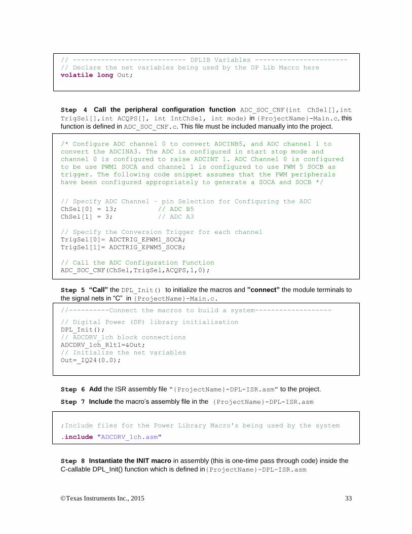
// ---------------------------- DPLIB Variables -----------------------
// Declare the net variables being used by the DP Lib Macro here
volatile long Out;
Step 4 Call the peripheral configuration function ADC_SOC_CNF(int ChSel[],int
TrigSel[],int ACQPS[], int IntChSel, int mode) in {ProjectName}-Main.c, this
function is defined in ADC_SOC_CNF.c. This file must be included manually into the project.
/* Configure ADC channel 0 to convert ADCINB5, and ADC channel 1 to
convert the ADCINA3. The ADC is configured in start stop mode and
channel 0 is configured to raise ADCINT 1. ADC Channel 0 is configured
to be use PWM1 SOCA and channel 1 is configured to use PWM 5 SOCB as
trigger. The following code snippet assumes that the PWM peripherals
have been configured appropriately to generate a SOCA and SOCB */
// Specify ADC Channel – pin Selection for Configuring the ADC
ChSel[0] = 13; // ADC B5
ChSel[1] = 3; // ADC A3
// Specify the Conversion Trigger for each channel
TrigSel[0]= ADCTRIG_EPWM1_SOCA;
TrigSel[1]= ADCTRIG_EPWM5_SOCB;
// Call the ADC Configuration Function
ADC_SOC_CNF(ChSel,TrigSel,ACQPS,1,0);
Step 5 “Call” the DPL_Init() to initialize the macros and ”connect” the module terminals to
the signal nets in “C” in {ProjectName}-Main.c.
//----------Connect the macros to build a system-------------------
// Digital Power (DP) library initialisation
DPL_Init();
// ADCDRV_1ch block connections
ADCDRV_1ch_Rlt1=&Out;
// Initialize the net variables
Out=_IQ24(0.0);
Step 6 Add the ISR assembly file “{ProjectName}-DPL-ISR.asm” to the project.
Step 7 Include the macro’s assembly file in the {ProjectName}-DPL-ISR.asm
;Include files for the Power Library Macro's being used by the system
.include "ADCDRV_1ch.asm"
Step 8 Instantiate the INIT macro in assembly (this is one-time pass through code) inside the
C-callable DPL_Init() function which is defined in{ProjectName}-DPL-ISR.asm

Texas Instruments Inc., 2015 34
;Macro Specific Initialization Functions
ADCDRV_1ch_INIT 1 ; ADCDRV_1ch Initialization
Step 9 Call the run time macro in assembly inside the C-callable function DPL_ISR() which
is the looped or ISR code. The function is defined in{ProjectName}-DPL-ISR.asm
;”Call” the Run macro
ADCDRV_1ch 1 ; Run ADCDRV_1ch
Step 10 Include the memory sections in the {DeviceName}-{RAM/FLASH}-
{ProjectName}.CMD. Note that the net pointers and the internal data are forced to be placed
in a single data page by use of the .usect directive in the source file of the module.
/*ADCDRV_1ch sections*/
ADCDRV_1ch_Section : > dataRAM PAGE = 1
Module Net Definition:
Net name (:n: is the instance number)
Description Format
Acceptable Range of Variable or of the Variable being pointed to
ADCDRV_1ch_Rlt:n:
Output Pointer
Pointer to 32 bit fixed point data location storing the result of the module.
Q24: [0, 1)

Texas Instruments Inc., 2015 35
5.3.2 ADCDRV_4ch : ADC Driver Four Channel
Description: This assembly macro reads four results from the internal ADC module result registers m,n,p,q and delivers them in Q24 format to the output terminals. The output is normalized to 0-1.0 such that the minimum input voltage will generate nominally 0.0 at the driver output, and a maximum full scale input voltage read +1.0. The result are then stored in the memory location pointed to by the net terminal pointers.
ADCDRV_4ch_RltA
ADC Ch:x:ADC
ADCDRV_4ch:m,n,p,q:
RltPtrA
ADC Ch:y:
ADC Ch:z:
ADC Ch:w:
RltPtrB
RltPtrC
RltPtrD
ADCDRV_4ch_RltB
ADCDRV_4ch_RltC
ADCDRV_4ch_RltD
Macro File: ADCDRV_4ch.asm
Peripheral
Initialization File: ADC_SOC_Cnf.c
Description: The ADC module in the F2802x & F2803x devices includes a ratio-metric
input which enables the user to determine the maximum and minimum input voltages. The ADC converts this input range with 12-bits of resolution. The ADCDRV macro reads the result register (determined by the numbers that are parsed to the run time macro m,n,p and q. The module then scales these to Q24 format and writes the result in unipolar Q24 format to the output net terminal.
This macro is used in conjunction with the peripheral configuration file ADC_SOC_Cnf.c
Multiple instantiation of this macro is not supported.
Usage:
Step 1 Add library header file in the file {ProjectName}-Main.c
#include “DPLib.h”
Step 2 Declare the terminal pointers in C in the file {ProjectName}-Main.c
// ---------------------------- DPLIB Net Pointers --------------------
// Declare net pointers that are used to connect the DP Lib Macros here
// and the data variables being used by the macros internally
//ADCDRV_4ch
extern volatile long *ADCDRV_4ch_RltA;
extern volatile long *ADCDRV_4ch_RltB; extern volatile long *ADCDRV_4ch_RltC;
extern volatile long *ADCDRV_4ch_RltD;
Step 3 Declare signal net nodes/ variables in C in the file {ProjectName}-Main.c
Texas Instruments Inc., 2015 36
Note signal net node names change from system to system, no dependency exist between these names and module.
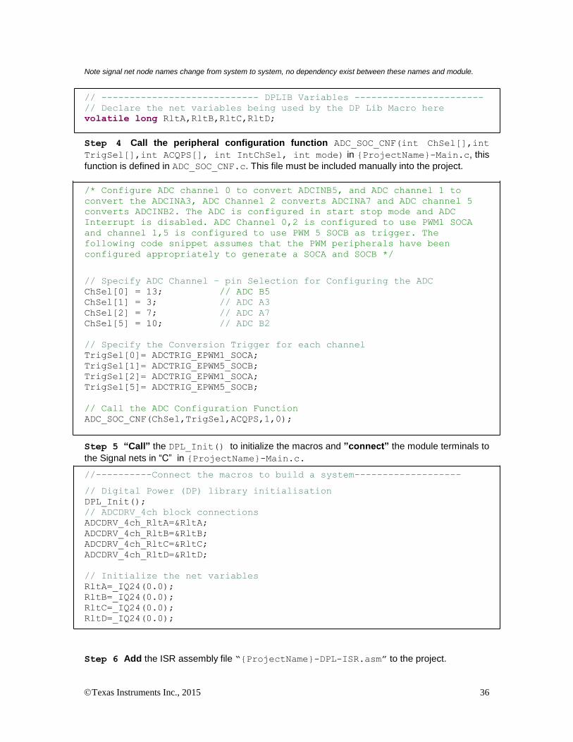
// ---------------------------- DPLIB Variables -----------------------
// Declare the net variables being used by the DP Lib Macro here
volatile long RltA,RltB,RltC,RltD;
Step 4 Call the peripheral configuration function ADC_SOC_CNF(int ChSel[],int
TrigSel[],int ACQPS[], int IntChSel, int mode) in {ProjectName}-Main.c, this
function is defined in ADC_SOC_CNF.c. This file must be included manually into the project.
/* Configure ADC channel 0 to convert ADCINB5, and ADC channel 1 to
convert the ADCINA3, ADC Channel 2 converts ADCINA7 and ADC channel 5
converts ADCINB2. The ADC is configured in start stop mode and ADC
Interrupt is disabled. ADC Channel 0,2 is configured to use PWM1 SOCA
and channel 1,5 is configured to use PWM 5 SOCB as trigger. The
following code snippet assumes that the PWM peripherals have been
configured appropriately to generate a SOCA and SOCB */
// Specify ADC Channel – pin Selection for Configuring the ADC
ChSel[0] = 13; // ADC B5
ChSel[1] = 3; // ADC A3
ChSel[2] = 7; // ADC A7
ChSel[5] = 10; // ADC B2
// Specify the Conversion Trigger for each channel
TrigSel[0]= ADCTRIG_EPWM1_SOCA;
TrigSel[1]= ADCTRIG_EPWM5_SOCB;
TrigSel[2]= ADCTRIG_EPWM1_SOCA;
TrigSel[5]= ADCTRIG_EPWM5_SOCB;
// Call the ADC Configuration Function
ADC_SOC_CNF(ChSel,TrigSel,ACQPS,1,0);
Step 5 “Call” the DPL_Init() to initialize the macros and ”connect” the module terminals to
the Signal nets in “C” in {ProjectName}-Main.c.
//----------Connect the macros to build a system-------------------
// Digital Power (DP) library initialisation
DPL_Init();
// ADCDRV_4ch block connections
ADCDRV_4ch_RltA=&RltA;
ADCDRV_4ch_RltB=&RltB;
ADCDRV_4ch_RltC=&RltC;
ADCDRV_4ch_RltD=&RltD;
// Initialize the net variables
RltA=_IQ24(0.0);
RltB=_IQ24(0.0);
RltC=_IQ24(0.0);
RltD=_IQ24(0.0);
Step 6 Add the ISR assembly file “{ProjectName}-DPL-ISR.asm” to the project.

Texas Instruments Inc., 2015 37
Step 7 Include the macro’s assembly file in the {ProjectName}-DPL-ISR.asm
;Include files for the Power Library Macro's being used by the system
.include "ADCDRV_4ch.asm"
Step 8 Instantiate the INIT macro in assembly (this is one-time pass through code) inside the
C-callable DPL_Init() function which is defined in{ProjectName}-DPL-ISR.asm. Four
numbers need to be specified to identify which result registers would be read and scaled results written to the respective pointers. The following code snippet would do the following
AdcResult.ADCRESULT0 -> (Scale) -> *(ADCDRV_4ch_RltA)
AdcResult.ADCRESULT5 -> (Scale) -> *(ADCDRV_4ch_RltB)
AdcResult.ADCRESULT2 -> (Scale) -> *(ADCDRV_4ch_RltC)
AdcResult.ADCSESULT1 -> (Scale) -> *(ADCDRV_4ch_RltD)
;Macro Specific Initialization Functions
ADCDRV_4ch_INIT 0,5,2,1 ; ADCDRV_4ch Initialization
Step 9 Call the run time macro in assembly inside the C-callable function DPL_ISR() which
is the looped or ISR code. The function is defined in{ProjectName}-DPL-ISR.asm
;”Call” the Run macro
ADCDRV_4ch 0,5,2,1 ; Run ADCDRV_4ch
Step 10 Include the memory sections in the {DeviceName}-{RAM/FLASH}-
{ProjectName}.CMD. Note that the net pointers and the internal data are forced to be placed
in a single data page by use of the .usect directive in the source file of the module.
/*ADCDRV_4ch sections*/
ADCDRV_4ch_Section : > dataRAM PAGE = 1
Module Net Definition:
Net name (:n: is the instance number)
Description Format
Acceptable Range of Variable or of the Variable being pointed to
ADCDRV_4ch_RltA Output Pointer
Pointer to 32 bit fixed point data location storing the result of the module.
Q24: [0, 1)
ADCDRV_4ch_RltB Output Pointer
Pointer to 32 bit fixed point data location storing the result of the module.
Q24: [0, 1)
ADCDRV_4ch_RltC Output Pointer
Pointer to 32 bit fixed point data location storing the result of the module.
Q24: [0, 1)
ADCDRV_4ch_RltD Output Pointer
Pointer to 32 bit fixed point data location storing the result of the module.
Q24: [0, 1)

Texas Instruments Inc., 2015 38
5.3.3 ADCDRV_8ch : 8 channel ADC Driver
Description: This assembly macro reads eight results from the internal ADC module result registers m,n,p,q,r,s,t,u and delivers them in Q24 format to the output terminals. The output is normalized to 0-1.0 such that the minimum input voltage will generate nominally 0.0 at the driver output, and a maximum full scale input voltage read +1.0. The results are then stored in the memory locations pointed to by the net terminal pointers.
Macro File: ADCDRV_8ch.asm
Peripheral
Initialization File: ADC_SOC_Cnf.c
Description: The ADC module in the F2802x & F2803x devices includes a ratio-metric
input which enables the user to determine the maximum and minimum input voltages. The ADC converts this input range with 12-bits of resolution. The ADCDRV macro reads the result register (determined by the numbers that are parsed to the run time macro m,n,p,q,r,s,t and u. The module then scales these to Q24 format and writes the result in unipolar Q24 format to the output net terminal.
This macro is used in conjunction with the peripheral configuration file ADC_SOC_Cnf.c
Multiple instantiations of this macro are not supported.
Usage:
Step 1 Add library header file in the file {ProjectName}-Main.c
#include “DPLib.h”
ADCDRV_8ch_RltA
ADC Ch:t:
ADC
ADCDRV_8ch:m,n,p,q,r,s,t,u:
RltPtrA
ADC Ch:u:
ADC Ch:v:
ADC Ch:s:
RltPtrC
RltPtrE
RltPtrG
ADCDRV_8ch_RltB
ADCDRV_8ch_RltC
ADCDRV_8ch_RltD
ADCDRV_8ch_RltE
ADCDRV_8ch_RltF
ADCDRV_8ch_RltG
ADCDRV_8ch_RltH
RltPtrB
RltPtrD
RltPtrF
RltPtrH
ADC Ch:x:
ADC Ch:y:
ADC Ch:z:
ADC Ch:w:
Texas Instruments Inc., 2015 39
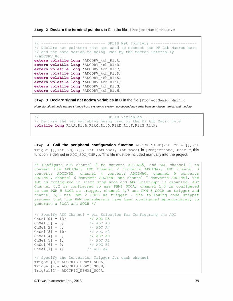
Step 2 Declare the terminal pointers in C in the file {ProjectName}-Main.c
// ---------------------------- DPLIB Net Pointers --------------------
// Declare net pointers that are used to connect the DP Lib Macros here
// and the data variables being used by the macros internally
//ADCDRV_8ch
extern volatile long *ADCDRV_4ch_RltA; extern volatile long *ADCDRV_4ch_RltB;
extern volatile long *ADCDRV_4ch_RltC; extern volatile long *ADCDRV_4ch_RltD;
extern volatile long *ADCDRV_4ch_RltE; extern volatile long *ADCDRV_4ch_RltF;
extern volatile long *ADCDRV_4ch_RltG; extern volatile long *ADCDRV_4ch_RltH;
Step 3 Declare signal net nodes/ variables in C in the file {ProjectName}-Main.c
Note signal net node names change from system to system, no dependency exist between these names and module.
// ---------------------------- DPLIB Variables -----------------------
// Declare the net variables being used by the DP Lib Macro here
volatile long RltA,RltB,RltC,RltD,RltE,RltF,RltG,RltH;
Step 4 Call the peripheral configuration function ADC_SOC_CNF(int ChSel[],int
TrigSel[],int ACQPS[], int IntChSel, int mode) in {ProjectName}-Main.c, this
function is defined in ADC_SOC_CNF.c. This file must be included manually into the project.
/* Configure ADC channel 0 to convert ADCINB5, and ADC channel 1 to
convert the ADCINA3, ADC Channel 2 converts ADCINA7, ADC channel 3
converts ADCINB2, channel 4 converts ADCINA0, channel 5 converts
ADCINA1, channel 6 converts ADCINB1 and channel 7 converts ADCINA4. The
ADC is configured in start stop mode and ADC Interrupt is disabled. ADC
Channel 0,2 is configured to use PWM1 SOCA, channel 1,3 is configured
to use PWM 5 SOCB as trigger, channel 4,7 use PWM 3 SOCA as trigger and
channel 5,6 use PWM 2 SOCB as trigger . The following code snippet
assumes that the PWM peripherals have been configured appropriately to
generate a SOCA and SOCB */
// Specify ADC Channel – pin Selection for Configuring the ADC
ChSel[0] = 13; // ADC B5
ChSel[1] = 3; // ADC A3
ChSel[2] = 7; // ADC A7
ChSel[3] = 10; // ADC B2
ChSel[4] = 0; // ADC A0
ChSel[5] = 1; // ADC A1
ChSel[6] = 9; // ADC B1
ChSel[7] = 4; // ADC A4
// Specify the Conversion Trigger for each channel
TrigSel[0]= ADCTRIG_EPWM1_SOCA;
TrigSel[1]= ADCTRIG_EPWM5_SOCB;
TrigSel[2]= ADCTRIG_EPWM1_SOCA;

Texas Instruments Inc., 2015 40
TrigSel[3]= ADCTRIG_EPWM5_SOCB;
TrigSel[4]= ADCTRIG_EPWM3_SOCA;
TrigSel[5]= ADCTRIG_EPWM2_SOCB;
TrigSel[6]= ADCTRIG_EPWM2_SOCB;
TrigSel[7]= ADCTRIG_EPWM3_SOCA;
// Call the ADC Configuration Function
ADC_SOC_CNF(ChSel,TrigSel,ACQPS,1,0);
Step 5 “Call” the DPL_Init() to initialize the macros and ”connect” the module terminals to
the Signal nets in “C” in {ProjectName}-Main.c.
//----------Connect the macros to build a system-------------------
// Digital Power (DP) library initialisation
DPL_Init();
// ADCDRV_8ch block connections
ADCDRV_8ch_RltA=&RltA;
ADCDRV_8ch_RltB=&RltB;
ADCDRV_8ch_RltC=&RltC;
ADCDRV_8ch_RltD=&RltD;
ADCDRV_8ch_RltE=&RltE;
ADCDRV_8ch_RltF=&RltF;
ADCDRV_8ch_RltG=&RltG;
ADCDRV_8ch_RltH=&RltH;
// Initialize the net variables
RltA=_IQ24(0.0);
RltB=_IQ24(0.0);
RltC=_IQ24(0.0);
RltD=_IQ24(0.0);
RltE=_IQ24(0.0);
RltF=_IQ24(0.0);
RltG=_IQ24(0.0);
RltH=_IQ24(0.0);
Step 6 Add the ISR assembly file “{ProjectName}-DPL-ISR.asm” to the project.
Step 7 Include the macro’s assembly file in the {ProjectName}-DPL-ISR.asm
;Include files for the Power Library Macro's being used by the system
.include "ADCDRV_8ch.asm"
Step 8 Instantiate the INIT macro in assembly (this is one-time pass through code) inside the
C-callable DPL_Init() function which is defined in{ProjectName}-DPL-ISR.asm. Eight
numbers need to be specified to identify which result registers would be read and scaled results written to the respective pointers. The following code snippet would do the following
AdcResult.ADCRESULT0 -> (Scale) -> *(ADCDRV_4ch_RltA)
AdcResult.ADCRESULT1 -> (Scale) -> *(ADCDRV_4ch_RltB)
AdcResult.ADCRESULT2 -> (Scale) -> *(ADCDRV_4ch_RltC)
AdcResult.ADCSESULT3 -> (Scale) -> *(ADCDRV_4ch_RltD)
AdcResult.ADCRESULT4 -> (Scale) -> *(ADCDRV_4ch_RltE)
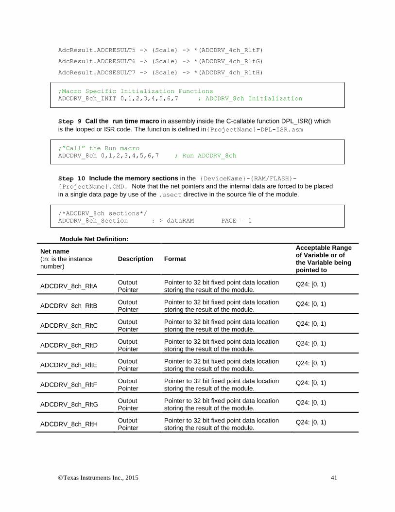
Texas Instruments Inc., 2015 41
AdcResult.ADCRESULT5 -> (Scale) -> *(ADCDRV_4ch_RltF)
AdcResult.ADCRESULT6 -> (Scale) -> *(ADCDRV_4ch_RltG)
AdcResult.ADCSESULT7 -> (Scale) -> *(ADCDRV_4ch_RltH)
;Macro Specific Initialization Functions
ADCDRV_8ch_INIT 0,1,2,3,4,5,6,7 ; ADCDRV_8ch Initialization
Step 9 Call the run time macro in assembly inside the C-callable function DPL_ISR() which
is the looped or ISR code. The function is defined in{ProjectName}-DPL-ISR.asm
;”Call” the Run macro
ADCDRV_8ch 0,1,2,3,4,5,6,7 ; Run ADCDRV_8ch
Step 10 Include the memory sections in the {DeviceName}-{RAM/FLASH}-
{ProjectName}.CMD. Note that the net pointers and the internal data are forced to be placed
in a single data page by use of the .usect directive in the source file of the module.
/*ADCDRV_8ch sections*/
ADCDRV_8ch_Section : > dataRAM PAGE = 1
Module Net Definition:
Net name (:n: is the instance number)
Description Format
Acceptable Range of Variable or of the Variable being pointed to
ADCDRV_8ch_RltA Output Pointer
Pointer to 32 bit fixed point data location storing the result of the module.
Q24: [0, 1)
ADCDRV_8ch_RltB Output Pointer
Pointer to 32 bit fixed point data location storing the result of the module.
Q24: [0, 1)
ADCDRV_8ch_RltC Output Pointer
Pointer to 32 bit fixed point data location storing the result of the module.
Q24: [0, 1)
ADCDRV_8ch_RltD Output Pointer
Pointer to 32 bit fixed point data location storing the result of the module.
Q24: [0, 1)
ADCDRV_8ch_RltE Output Pointer
Pointer to 32 bit fixed point data location storing the result of the module.
Q24: [0, 1)
ADCDRV_8ch_RltF Output Pointer
Pointer to 32 bit fixed point data location storing the result of the module.
Q24: [0, 1)
ADCDRV_8ch_RltG Output Pointer
Pointer to 32 bit fixed point data location storing the result of the module.
Q24: [0, 1)
ADCDRV_8ch_RltH Output Pointer
Pointer to 32 bit fixed point data location storing the result of the module.
Q24: [0, 1)

Texas Instruments Inc., 2015 42
5.3.4 PWMDRV_1ch : PWM Driver Single Channel
Description: This hardware driver module, when used in conjunction with the corresponding PWM configuration file, drives a duty on PWM channel A, dependent on the value of the input variable.
PWMDRV_1ch_Duty:n: PWM
PWMnA
PWMDRV_1ch:n:
Duty
Period
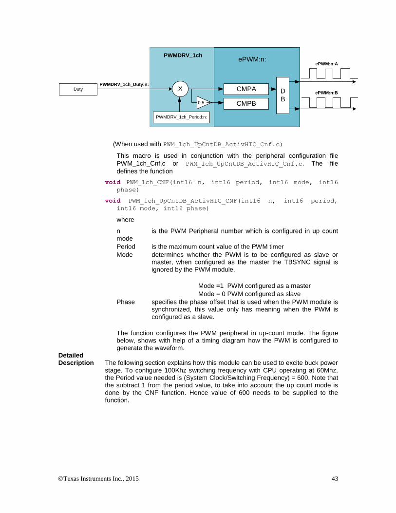
(When used with PWM_1ch_Cnf.c)
PWMnA
PWMnB
PWM
PWMDRV_1ch:n:
Duty
Period
PWMDRV_1ch_Duty:n:
(When used with PWM_1ch_UpCntDB_ActivHIC_Cnf.c)
Macro File: PWMDRV_1ch.asm
Peripheral
Initialization File: PWM_1ch_Cnf.c or PWM_1ch_UpCntDB_ActivHIC_Cnf.c
Description: This assembly macro provides the interface between a DP library net variable and the ePWM module on C28x. The macro converts the unsigned Q24 input, pointed to by the net pointer PWMDRV_1ch_Duty:n: into an unsigned Q0 number scaled by the PWM period value, and stores this value in the EPwmRegs:n:.CMPA. The module also writes half the value of CMPA into CMPB register. This is done to enable ADC start of conversions to occur close to the mid point of the PWM waveform to avoid switching noise. Which PWM Macro is driven and what period value is used for scaling is determined by the instance number of the macro i.e. :n:.
PWMDRV_1ch_Duty:n:
PWMDRV_1ch
ePWM:n:A
Duty
ePWM:n:
CMPA
PWMDRV_1ch_Period:n:
X
CMPB0.5
(When used with PWM_1ch_Cnf.c)
Texas Instruments Inc., 2015 43
PWMDRV_1ch_Duty:n:
PWMDRV_1ch
ePWM:n:A
Duty
ePWM:n:
CMPA
PWMDRV_1ch_Period:n:
X
CMPB0.5
ePWM:n:BD
B
(When used with PWM_1ch_UpCntDB_ActivHIC_Cnf.c)
This macro is used in conjunction with the peripheral configuration file
PWM_1ch_Cnf.c or PWM_1ch_UpCntDB_ActivHIC_Cnf.c. The file
defines the function
void PWM_1ch_CNF(int16 n, int16 period, int16 mode, int16
phase)
void PWM_1ch_UpCntDB_ActivHIC_CNF(int16 n, int16 period,
int16 mode, int16 phase)
where
n is the PWM Peripheral number which is configured in up count mode
Period is the maximum count value of the PWM timer
Mode determines whether the PWM is to be configured as slave or master, when configured as the master the TBSYNC signal is ignored by the PWM module.
Mode =1 PWM configured as a master
Mode = 0 PWM configured as slave
Phase specifies the phase offset that is used when the PWM module is synchronized, this value only has meaning when the PWM is configured as a slave.
The function configures the PWM peripheral in up-count mode. The figure below, shows with help of a timing diagram how the PWM is configured to generate the waveform.
Detailed Description The following section explains how this module can be used to excite buck power
stage. To configure 100Khz switching frequency with CPU operating at 60Mhz, the Period value needed is (System Clock/Switching Frequency) = 600. Note that the subtract 1 from the period value, to take into account the up count mode is done by the CNF function. Hence value of 600 needs to be supplied to the function.
Texas Instruments Inc., 2015 44
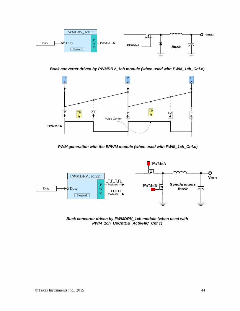
EPWMnA
Vout1
BuckDuty
PWM
PWMnA
PWMDRV_1ch:n:
Duty
Period
Buck converter driven by PWMDRV_1ch module (when used with PWM_1ch_Cnf.c)
EPWMnA
CB
APulse Center
CAP P PCACB
A
P
Z
P
Z
P
Z
PWM generation with the EPWM module (when used with PWM_1ch_Cnf.c)
Synchronous
BuckDuty
PWMnA
PWMnB
PWM
PWMDRV_1ch:n:
Duty
Period
PWMnB
PWMnA
VOUT
Buck converter driven by PWMDRV_1ch module (when used with PWM_1ch_UpCntDB_ActivHIC_Cnf.c)
Texas Instruments Inc., 2015 45
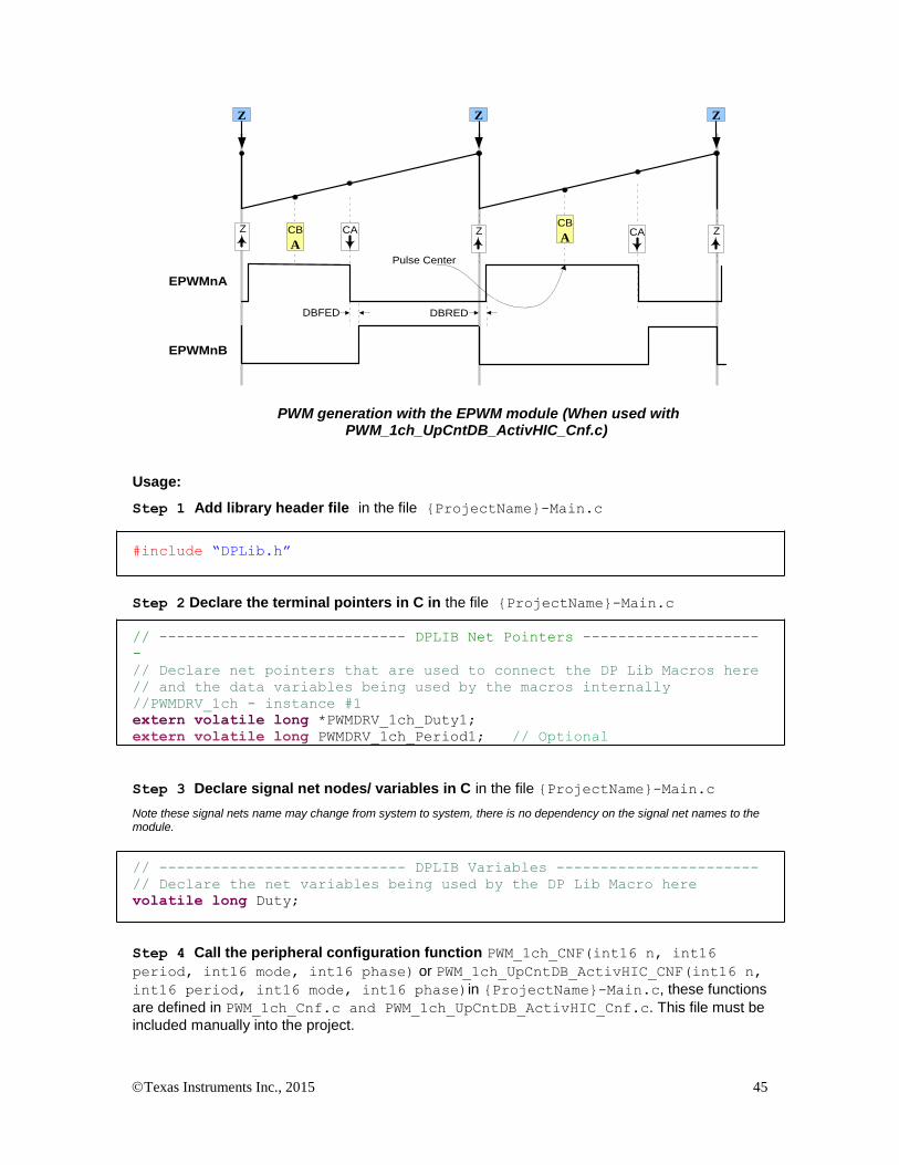
EPWMnA
CB
A
Pulse Center
CAZ Z ZCACB
A
Z Z Z
EPWMnB
DBFED DBRED
PWM generation with the EPWM module (When used with PWM_1ch_UpCntDB_ActivHIC_Cnf.c)
Usage:
Step 1 Add library header file in the file {ProjectName}-Main.c
#include “DPLib.h”
Step 2 Declare the terminal pointers in C in the file {ProjectName}-Main.c
// ---------------------------- DPLIB Net Pointers --------------------
-
// Declare net pointers that are used to connect the DP Lib Macros here
// and the data variables being used by the macros internally
//PWMDRV_1ch - instance #1
extern volatile long *PWMDRV_1ch_Duty1;
extern volatile long PWMDRV_1ch_Period1; // Optional
Step 3 Declare signal net nodes/ variables in C in the file {ProjectName}-Main.c
Note these signal nets name may change from system to system, there is no dependency on the signal net names to the module.
// ---------------------------- DPLIB Variables -----------------------
// Declare the net variables being used by the DP Lib Macro here
volatile long Duty;
Step 4 Call the peripheral configuration function PWM_1ch_CNF(int16 n, int16
period, int16 mode, int16 phase) or PWM_1ch_UpCntDB_ActivHIC_CNF(int16 n,
int16 period, int16 mode, int16 phase)in {ProjectName}-Main.c, these functions
are defined in PWM_1ch_Cnf.c and PWM_1ch_UpCntDB_ActivHIC_Cnf.c. This file must be
included manually into the project.
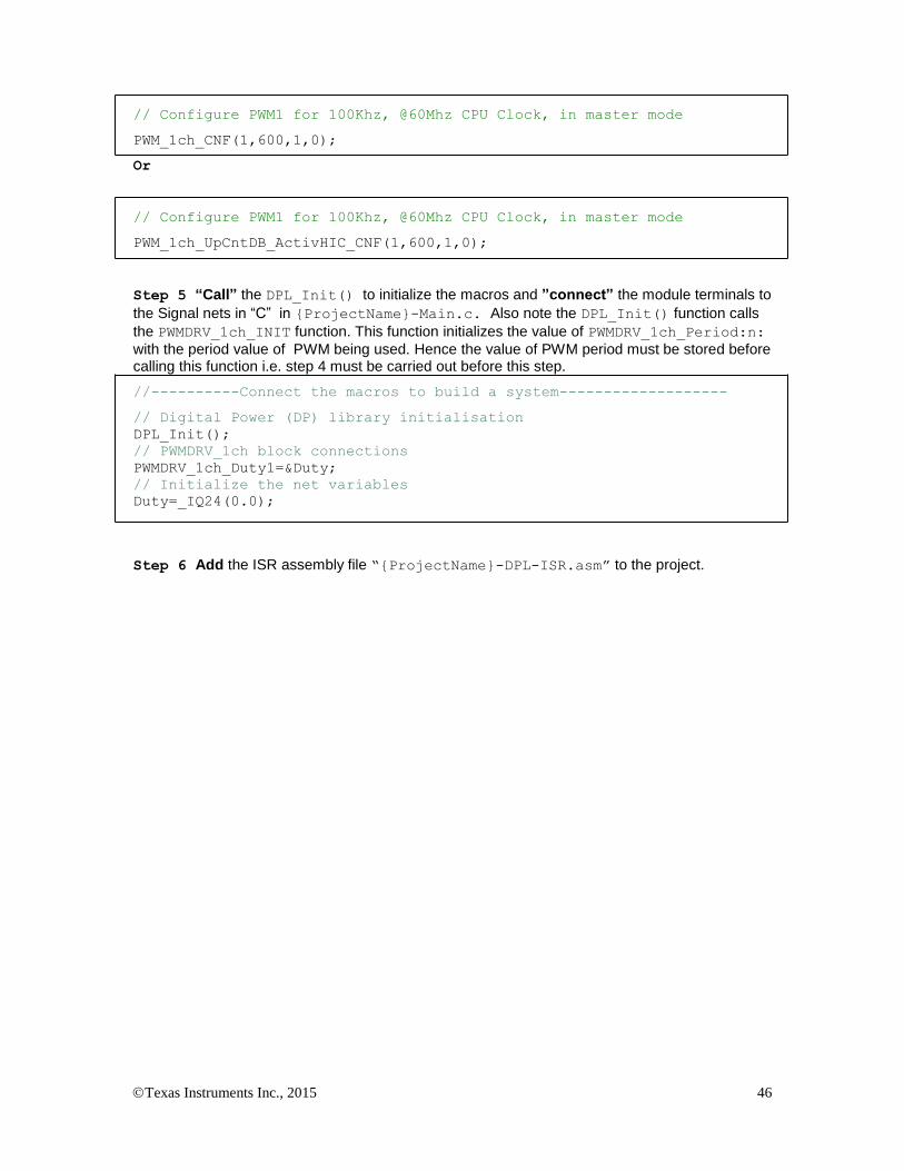
Texas Instruments Inc., 2015 46
// Configure PWM1 for 100Khz, @60Mhz CPU Clock, in master mode
PWM_1ch_CNF(1,600,1,0);
Or
// Configure PWM1 for 100Khz, @60Mhz CPU Clock, in master mode
PWM_1ch_UpCntDB_ActivHIC_CNF(1,600,1,0);
Step 5 “Call” the DPL_Init() to initialize the macros and ”connect” the module terminals to
the Signal nets in “C” in {ProjectName}-Main.c. Also note the DPL_Init() function calls
the PWMDRV_1ch_INIT function. This function initializes the value of PWMDRV_1ch_Period:n:
with the period value of PWM being used. Hence the value of PWM period must be stored before calling this function i.e. step 4 must be carried out before this step.
//----------Connect the macros to build a system-------------------
// Digital Power (DP) library initialisation
DPL_Init();
// PWMDRV_1ch block connections
PWMDRV_1ch_Duty1=&Duty;
// Initialize the net variables
Duty=_IQ24(0.0);
Step 6 Add the ISR assembly file “{ProjectName}-DPL-ISR.asm” to the project.
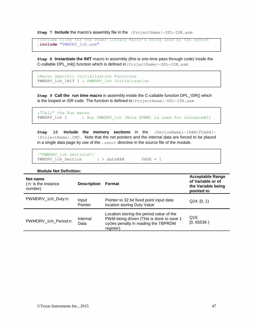
Texas Instruments Inc., 2015 47
Step 7 Include the macro’s assembly file in the {ProjectName}-DPL-ISR.asm
;Include files for the Power Library Macro's being used by the system
.include "PWMDRV_1ch.asm"
Step 8 Instantiate the INIT macro in assembly (this is one-time pass through code) inside the
C-callable DPL_Init() function which is defined in{ProjectName}-DPL-ISR.asm
;Macro Specific Initialization Functions
PWMDRV_1ch_INIT 1 ; PWMDRV_1ch Initialization
Step 9 Call the run time macro in assembly inside the C-callable function DPL_ISR() which
is the looped or ISR code. The function is defined in{ProjectName}-DPL-ISR.asm
;”Call” the Run macro
PWMDRV_1ch 1 ; Run PWMDRV_1ch (Note EPWM1 is used for instance#1)
Step 10 Include the memory sections in the {DeviceName}-{RAM/FLASH}-
{ProjectName}.CMD. Note that the net pointers and the internal data are forced to be placed
in a single data page by use of the .usect directive in the source file of the module.
/*PWMDRV_1ch sections*/
PWMDRV_1ch_Section : > dataRAM PAGE = 1
Module Net Definition:
Net name (:n: is the instance number)
Description Format
Acceptable Range of Variable or of the Variable being pointed to
PWMDRV_1ch_Duty:n:
Input Pointer
Pointer to 32 bit fixed point input data location storing Duty Value
Q24: [0, 1)
PWMDRV_1ch_Period:n: Internal Data
Location storing the period value of the PWM being driven (This is done to save 1 cycles penalty in reading the TBPRDM register)
Q16: [0, 65536 )
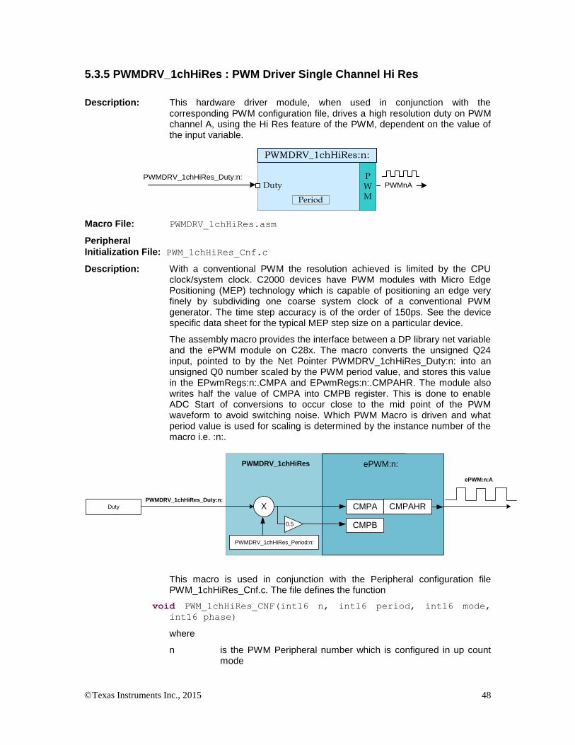
Texas Instruments Inc., 2015 48
5.3.5 PWMDRV_1chHiRes : PWM Driver Single Channel Hi Res
Description: This hardware driver module, when used in conjunction with the corresponding PWM configuration file, drives a high resolution duty on PWM channel A, using the Hi Res feature of the PWM, dependent on the value of the input variable.
PWMDRV_1chHiRes_Duty:n: PWM
PWMnA
PWMDRV_1chHiRes:n:
Duty
Period
Macro File: PWMDRV_1chHiRes.asm
Peripheral
Initialization File: PWM_1chHiRes_Cnf.c
Description: With a conventional PWM the resolution achieved is limited by the CPU clock/system clock. C2000 devices have PWM modules with Micro Edge Positioning (MEP) technology which is capable of positioning an edge very finely by subdividing one coarse system clock of a conventional PWM generator. The time step accuracy is of the order of 150ps. See the device specific data sheet for the typical MEP step size on a particular device.
The assembly macro provides the interface between a DP library net variable and the ePWM module on C28x. The macro converts the unsigned Q24 input, pointed to by the Net Pointer PWMDRV_1chHiRes_Duty:n: into an unsigned Q0 number scaled by the PWM period value, and stores this value in the EPwmRegs:n:.CMPA and EPwmRegs:n:.CMPAHR. The module also writes half the value of CMPA into CMPB register. This is done to enable ADC Start of conversions to occur close to the mid point of the PWM waveform to avoid switching noise. Which PWM Macro is driven and what period value is used for scaling is determined by the instance number of the macro i.e. :n:.
PWMDRV_1chHiRes_Duty:n:
PWMDRV_1chHiRes
ePWM:n:A
Duty
ePWM:n:
CMPA
PWMDRV_1chHiRes_Period:n:
X
CMPB0.5
CMPAHR
This macro is used in conjunction with the Peripheral configuration file PWM_1chHiRes_Cnf.c. The file defines the function
void PWM_1chHiRes_CNF(int16 n, int16 period, int16 mode,
int16 phase)
where
n is the PWM Peripheral number which is configured in up count mode

Texas Instruments Inc., 2015 49
Period is the maximum count value of the PWM timer
Mode determines whether the PWM is to be configured as slave or master,when configured as the master the TBSYNC signal is ignored by the PWM module.
Mode =1 PWM configured as a master
Mode = 0 PWM configured as slave
Phase Specifies the phase offset that is used when the PWM module is synced, this value only has meaning when the PWM is configured as a slave.
The function configures the PWM peripheral in up count mode. The figure below, shows with help of a timing diagram how the PWM is configured to generate the waveform. To configure 100Khz switching frequency with CPU operating at 60Mhz, the Period value needed is (System Clock/Switching Frequency) = 600. Note that the subtract 1 from the period value to take into account the up count mode is done by the CNF function. Hence value 600 needs to be supplied to the function.
EPWM1A
CB
APulse Center
CAP P PCACB
A
P
Z
P
Z
P
Z
SysClk
MEP Step
PWM generation with the EPWM module.
Note: The MEP varies from device to device and operating condition, for the module to work appropriately a Scale Factor Optimization (SFO) function must be called in a slower background task to auto calibrate the MEP step size. Note the SFO function can only be called by the CPU and not the CLA

Texas Instruments Inc., 2015 50
Usage:
Step 1 Add library header file and the Scale Factor Optimizer Library header in the file
{ProjectName}-Main.c. Please use V6 or higher of the SFO library for this module to work
appropriately. The Library also needs to included in the project manually. The Library can be found at
controlSUITE\device_support\<Device_Name>\<Version>\<Device_Name>_commo
n\lib
#include “DPLib.h”
#include "SFO_V6.h"
Step 2 Declare the terminal pointers in C in the file {ProjectName}-Main.c and add
variable declaration for the variables being used by the SFO Library.
// ---------------------------- DPLIB Net Pointers --------------------
-
// Declare net pointers that are used to connect the DP Lib Macros here
// and the data variables being used by the macros internally
//PWMDRV_1chHiRes - instance #1
extern volatile long *PWMDRV_1chHiRes_Duty1;
extern volatile long PWMDRV_1chHiRes_Period1; // Optional
//====================================================================
// The following declarations are required in order to use the SFO
// library functions:
//
int MEP_ScaleFactor; // Global variable used by the SFO library
// Result can be used for all HRPWM channels
// This variable is also copied to HRMSTEP
// register by SFO() function.
int status;
Step 3 Declare signal net nodes/ variables in C in the file {ProjectName}-Main.c
Note these signal nets name may change from system to system, there is no dependency on the signal net names to the module.
// ---------------------------- DPLIB Variables -----------------------
// Declare the net variables being used by the DP Lib Macro here
volatile long Duty;
Step 4 Call the peripheral configuration function PWM_1chHiRes_CNF(int16 n, int16
period, int16 mode, int16 phase) in {ProjectName}-Main.c, this function is defined
in PWM_1chHiRes_Cnf.c. This file must be included manually into the project.
// Configure PWM1 for 100Khz, @60Mhz CPU Clock, in master mode
PWM_1chHiRes_CNF(1,600,1,0);
Step 5 “Call” the DPL_Init() to initialize the macros and ”connect” the module terminals to
the signal nets in “C” in {ProjectName}-Main.c. Also note the DPL_Init() function calls

Texas Instruments Inc., 2015 51
the PWMDRV_1ch_INIT function. This function initializes the value of
PWMDRV_1chHiRes_Period:n: with the period value of PWM being used. Hence the value of
PWM period must be stored before calling this function i.e. step 4 must be carried out before this step. “Call” the SFO() function to calculate the HRMSTEP, and update the HRMSTEP register if calibration function returns without error. The User may want to call this function in a background task to account for changing operating conditions.
//----------Connect the macros to build a system-------------------
// Digital Power (DP) library initialisation
DPL_Init();
// PWMDRV_1ch block connections
PWMDRV_1chHiRes_Duty1=&Duty;
// Calling SFO() updates the HRMSTEP register with calibrated
MEP_ScaleFactor.
// MEP_ScaleFactor/HRMSTEP must be filled with calibrated value in
order // for the module to work
status = SFO_INCOMPLETE;
while (status== SFO_INCOMPLETE){ // Call until complete
status = SFO();
}
if(status!=SFO_ERROR) { // IF SFO() is complete with no errors
EALLOW;
EPwm1Regs.HRMSTEP=MEP_ScaleFactor;
EDIS;
}
if (status == SFO_ERROR) {
while(1); // SFO function returns 2 if an error occurs
// The code would loop here for infinity if it
// returns an error
}
// Initialize the net variables
Duty=_IQ24(0.0);
Step 6 Add the ISR assembly file “{ProjectName}-DPL-ISR.asm” to the project.
Step 7 Include the macro’s assembly file in the {ProjectName}-DPL-ISR.asm
;Include files for the Power Library Macro's being used by the system
.include "PWMDRV_1chHiRes.asm"
Step 8 Instantiate the INIT macro in assembly (this is one-time pass through code) inside the
C-callable DPL_Init() function which is defined in{ProjectName}-DPL-ISR.asm
;Macro Specific Initialization Functions
PWMDRV_1chHiRes_INIT 1 ; PWMDRV_1ch Initialization
Step 9 Call the run time macro in assembly inside the C-callable function DPL_ISR() which
is the looped or ISR code. The function is defined in{ProjectName}-DPL-ISR.asm
;”Call” the Run macro
PWMDRV_1chHiRes 1 ; Run PWMDRV_1ch (Note EPWM1 is used for instance#1)

Texas Instruments Inc., 2015 52
Step 10 Include the memory sections in the {DeviceName}-{RAM/FLASH}-
{ProjectName}.CMD. Note that the net pointers and the internal data are forced to be placed
in a single data page by use of the .usect directive in the source file of the module.
/*PWMDRV_1ch sections*/
PWMDRV_1chHiRes_Section : > dataRAM PAGE = 1
Module Net Definition:
Net name (:n: is the instance number)
Description Format
Acceptable Range of Variable or of the Variable being pointed to
PWMDRV_1chHiRes_Duty:n:
Input Pointer
Pointer to 32 bit fixed point input data location storing Duty Value
Q24: [0, 1)
PWMDRV_1chHiRes_Period:n: Internal Data
Location storing the period value of the PWM being driven (This is done to save 1 cycles penalty in reading the TBPRDM register)
Q16: [0, 65536 )

Texas Instruments Inc., 2015 53
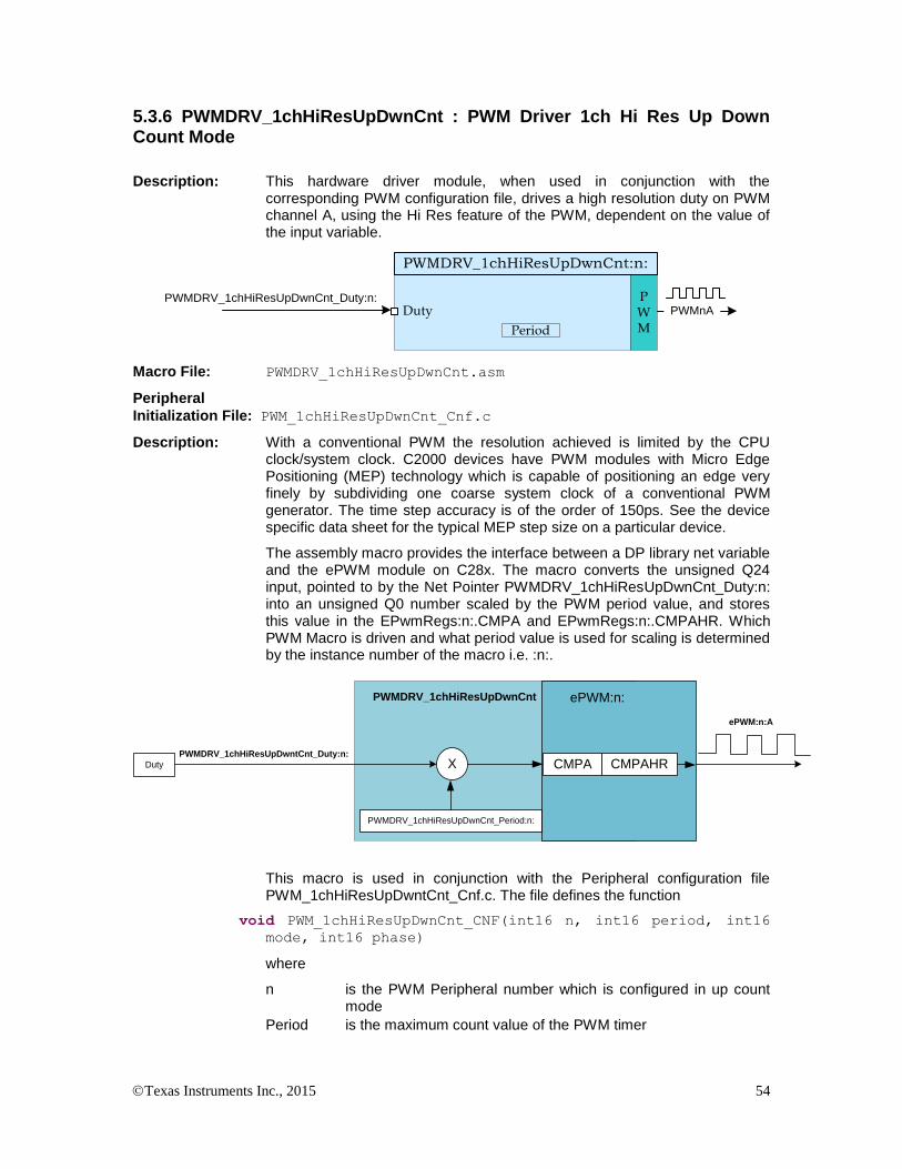
Texas Instruments Inc., 2015 54
5.3.6 PWMDRV_1chHiResUpDwnCnt : PWM Driver 1ch Hi Res Up Down Count Mode
Description: This hardware driver module, when used in conjunction with the corresponding PWM configuration file, drives a high resolution duty on PWM channel A, using the Hi Res feature of the PWM, dependent on the value of the input variable.
PWMDRV_1chHiResUpDwnCnt_Duty:n: PWM
PWMnA
PWMDRV_1chHiResUpDwnCnt:n:
Duty
Period
Macro File: PWMDRV_1chHiResUpDwnCnt.asm
Peripheral
Initialization File: PWM_1chHiResUpDwnCnt_Cnf.c
Description: With a conventional PWM the resolution achieved is limited by the CPU clock/system clock. C2000 devices have PWM modules with Micro Edge Positioning (MEP) technology which is capable of positioning an edge very finely by subdividing one coarse system clock of a conventional PWM generator. The time step accuracy is of the order of 150ps. See the device specific data sheet for the typical MEP step size on a particular device.
The assembly macro provides the interface between a DP library net variable and the ePWM module on C28x. The macro converts the unsigned Q24 input, pointed to by the Net Pointer PWMDRV_1chHiResUpDwnCnt_Duty:n: into an unsigned Q0 number scaled by the PWM period value, and stores this value in the EPwmRegs:n:.CMPA and EPwmRegs:n:.CMPAHR. Which PWM Macro is driven and what period value is used for scaling is determined by the instance number of the macro i.e. :n:.
PWMDRV_1chHiResUpDwntCnt_Duty:n:
PWMDRV_1chHiResUpDwnCnt
ePWM:n:A
Duty
ePWM:n:
CMPA
PWMDRV_1chHiResUpDwnCnt_Period:n:
X CMPAHR
This macro is used in conjunction with the Peripheral configuration file PWM_1chHiResUpDwntCnt_Cnf.c. The file defines the function
void PWM_1chHiResUpDwnCnt_CNF(int16 n, int16 period, int16
mode, int16 phase)
where
n is the PWM Peripheral number which is configured in up count mode
Period is the maximum count value of the PWM timer

Texas Instruments Inc., 2015 55
Mode determines whether the PWM is to be configured as slave or master,when configured as the master the TBSYNC signal is ignored by the PWM module.
Mode =1 PWM configured as a master
Mode = 0 PWM configured as slave
Phase Specifies the phase offset that is used when the PWM module is synced, this value only has meaning when the PWM is configured as a slave.
The function configures the PWM peripheral in up down count mode. The figure below, shows with help of a timing diagram how the PWM is configured to generate the waveform. To configure 100Khz switching frequency with CPU operating at 60Mhz, the Period value needed for the CNF function is (System Clock/Switching Frequency) = 600. The devide by two for up down count mode it taken into account by the CNF function itself.
TimeBase
PWMn
PWM Sync Pulse
Z P Z ZPTBPRD
ADC Soc
ADC Soc
Hi-Res
CA CA
EPWMnA
Dbu
SysClk
MEP Step
PWM generation with the EPWM module.
Note: The MEP varies from device to device and operating condition, for the module to work appropriately a Scale Factor Optimization (SFO) function must be called in a slower background task to auto calibrate the MEP step size. Note the SFO function can only be called by the CPU and not the CLA

Texas Instruments Inc., 2015 56
Usage:
Step 1 Add library header file and the Scale Factor Optimizer Library header in the file
{ProjectName}-Main.c. Please use V6 or higher of the SFO library for this module to work
appropriately. The Library also needs to included in the project manually. The Library can be found at
controlSUITE\device_support\<Device_Name>\<Version>\<Device_Name>_commo
n\lib
#include “DPLib.h”
#include "SFO_V6.h"
Step 2 Declare the terminal pointers in C in the file {ProjectName}-Main.c and add
variable declaration for the variables being used by the SFO Library.
// ---------------------------- DPLIB Net Pointers --------------------
-
// Declare net pointers that are used to connect the DP Lib Macros here
// and the data variables being used by the macros internally
//PWMDRV_1chHiRes - instance #1
extern volatile long *PWMDRV_1chHiResUpDwnCnt_Duty1;
extern volatile long PWMDRV_1chHiResUpDwnCnt_Period1; // Optional
//====================================================================
// The following declarations are required in order to use the SFO
// library functions:
//
int MEP_ScaleFactor; // Global variable used by the SFO library
// Result can be used for all HRPWM channels
// This variable is also copied to HRMSTEP
// register by SFO() function.
int status;
Step 3 Declare signal net nodes/ variables in C in the file {ProjectName}-Main.c
Note these signal nets name may change from system to system, there is no dependency on the signal net names to the module.
// ---------------------------- DPLIB Variables -----------------------
// Declare the net variables being used by the DP Lib Macro here
volatile long Duty;
Step 4 Call the peripheral configuration function PWM_1chHiResUpDwnCnt_CNF(int16
n, int16 period, int16 mode, int16 phase) in {ProjectName}-Main.c, this
function is defined in PWM_1chHiResUpDwnCnt_Cnf.c. This file must be included manually into
the project.
// Configure PWM1 for 100Khz, @60Mhz CPU Clock, in master mode
PWM_1chHiResUpDwnCnt_CNF(1,600,1,0);

Texas Instruments Inc., 2015 57
Step 5 “Call” the DPL_Init() to initialize the macros and ”connect” the module terminals to
the signal nets in “C” in {ProjectName}-Main.c. Also note the DPL_Init() function calls
the PWMDRV_1chHiResUpDwnCnt_INIT function. This function initializes the value of
PWMDRV_1chHiResUpDwnCnt_Period:n: with the period value of PWM being used. Hence
the value of PWM period must be stored before calling this function i.e. step 4 must be carried out before this step. “Call” the SFO() function to calculate the HRMSTEP, and update the HRMSTEP register if calibration function returns without error. The User may want to call this function in a background task to account for changing operating conditions.
//----------Connect the macros to build a system-------------------
// Digital Power (DP) library initialisation
DPL_Init();
// PWMDRV_1ch block connections
PWMDRV_1chHiResUpDwnCnt_Duty1=&Duty;
// Calling SFO() updates the HRMSTEP register with calibrated
MEP_ScaleFactor.
// MEP_ScaleFactor/HRMSTEP must be filled with calibrated value in
order // for the module to work
status = SFO_INCOMPLETE;
while (status== SFO_INCOMPLETE){ // Call until complete
status = SFO();
}
if(status!=SFO_ERROR) { // IF SFO() is complete with no errors
EALLOW;
EPwm1Regs.HRMSTEP=MEP_ScaleFactor;
EDIS;
}
if (status == SFO_ERROR) {
while(1); // SFO function returns 2 if an error occurs
// The code would loop here for infinity if it
// returns an error
}
// Initialize the net variables
Duty=_IQ24(0.0);
Step 6 Add the ISR assembly file “{ProjectName}-DPL-ISR.asm” to the project.
Step 7 Include the macro’s assembly file in the {ProjectName}-DPL-ISR.asm
;Include files for the Power Library Macro's being used by the system
.include "PWMDRV_1chHiResUpDwnCnt.asm"
Step 8 Instantiate the INIT macro in assembly (this is one-time pass through code) inside the
C-callable DPL_Init() function which is defined in{ProjectName}-DPL-ISR.asm
;Macro Specific Initialization Functions
PWMDRV_1chHiResUpDwnCnt_INIT 1
Step 9 Call the run time macro in assembly inside the C-callable function DPL_ISR() which
is the looped or ISR code. The function is defined in{ProjectName}-DPL-ISR.asm
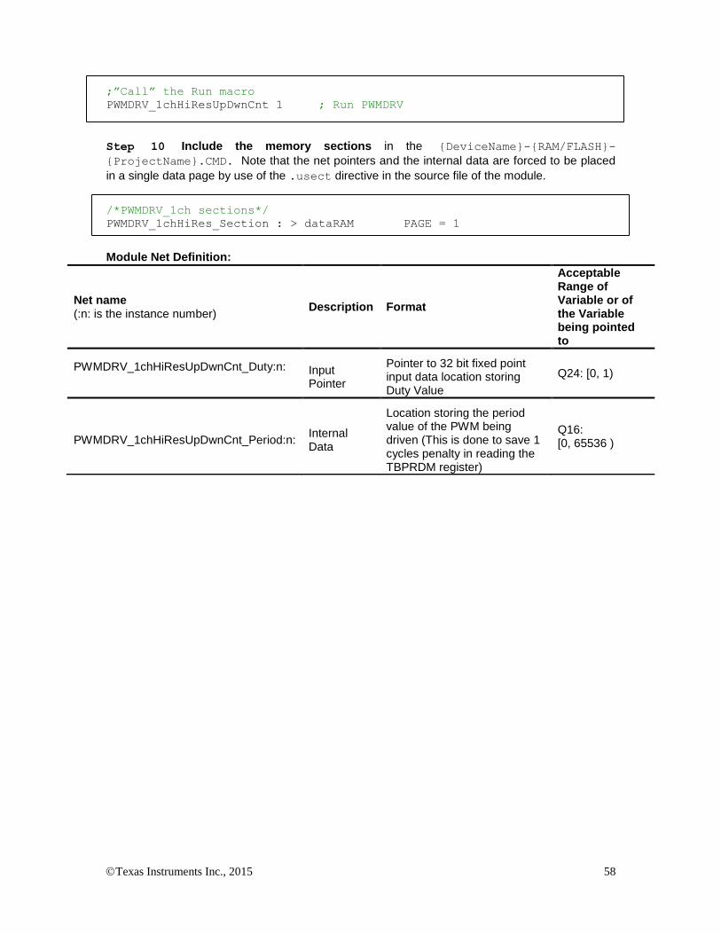
Texas Instruments Inc., 2015 58
;”Call” the Run macro
PWMDRV_1chHiResUpDwnCnt 1 ; Run PWMDRV
Step 10 Include the memory sections in the {DeviceName}-{RAM/FLASH}-
{ProjectName}.CMD. Note that the net pointers and the internal data are forced to be placed
in a single data page by use of the .usect directive in the source file of the module.
/*PWMDRV_1ch sections*/
PWMDRV_1chHiRes_Section : > dataRAM PAGE = 1
Module Net Definition:
Net name (:n: is the instance number)
Description Format
Acceptable Range of Variable or of the Variable being pointed to
PWMDRV_1chHiResUpDwnCnt_Duty:n:
Input Pointer
Pointer to 32 bit fixed point input data location storing Duty Value
Q24: [0, 1)
PWMDRV_1chHiResUpDwnCnt_Period:n: Internal Data
Location storing the period value of the PWM being driven (This is done to save 1 cycles penalty in reading the TBPRDM register)
Q16: [0, 65536 )

Texas Instruments Inc., 2015 59
5.3.7 PWMDRV_PFC2PHIL : PWM Driver for Two Phase Interleaved PFC Stage
Description: This hardware driver module, when used in conjunction with the corresponding PWM configuration file, controls two PWM generators that cane be used to drive a 2 phase interleaved PFC stage.
PWMDRV_PFC2PhiL_Duty:n:
PWMDRV_PFC2PhiL_Adj:n:
PWM
PWMnA
PWMDRV_PFC2PhiL:n:
Duty
Period
AdjPWMnB
Macro File: PWMDRV_PFC2PhiL.asm
Peripheral
Initialization File: PWM_PFC2PhiL_Cnf.c
Description: This module forms the interface between the control software and the device PWM pins. The macro converts the unsigned Q24 input pointed to by the Net Pointer PWMDRV_PFC2PhiL_Duty:n: into an unsigned Q0 number scaled by the PWM period value, and stores this value in the EPwmRegs:n:.CMPA. Which PWM module is written to is determined by the instance number of the macro i.e. :n:.
The value pointed by the PWMDRV_PFC2PhiL_Adj:n: stores a Q24 number that is scaled with the PWM period value to add an offset to the duty being driven on PWMnA and PWMnB. The value stored can be positive or negative depending on whether the duty driven on PWMnB needs to greater or smaller relative to PWMnA. In summary:
PWMPeriodDutyCMPA *
PWMPeriodDutyAdjCMPB *)1(
This macro is used in conjunction with the Peripheral configuration file PWM_PFC2PHIL_CNF.c. The file defines the function
void PWM_PFC2PHIL_CNF(int16 n, int16 period)
where
n is the PWM Peripheral number which is configured in up down count mode
Period is twice the maximum value of the PWM counter
The function configures the PWM peripheral in up down count mode. The figure below, shows with help of a timing diagram, how the PWM is configured to generate the waveform. When in up down count mode the zero and period event can be used to trigger ADC conversions at mid point of the switching duty.
Detailed Description The following section explains how this module can be used to excite a two
phase interleaved PFC stage. As up down count mode is used, to configure 200Khz switching frequency, at 60Mhz system clock the period value of

Texas Instruments Inc., 2015 60
(System Clock/Switching Frequency) = 300 must be used for the CNF function, the CNF function divides the value to take into account the up down count mode and stored TBPRD value of 300/2=150.
EPWM1A
VinVpfc_Out
Two Phase Interleaved PFC
Duty
Adj
EPWM1B
PWM
PWMnA
PWMDRV_PFC2PhiL:n:
Duty
Period
AdjPWMnB
PFC2PhiL driven by PWMDRV_PFC2PhiL module
EPWM1A
CAU CAD
CBU CBD
CAU CAD
EPWM1B
CBDCBU
Z P Z ZP
TBPRD TBPRD * Duty TBPRD*(1-Adj- Duty)
PWM generation for PFC2PhiL stage with the F280x EPWM module.
Usage:
Step 1 Add library header file in the file {ProjectName}-Main.c
#include “DPLib.h”
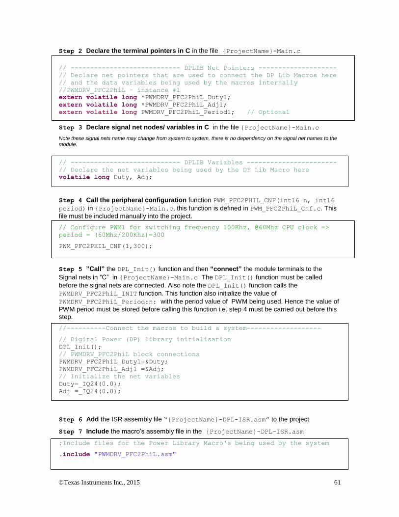
Texas Instruments Inc., 2015 61
Step 2 Declare the terminal pointers in C in the file {ProjectName}-Main.c
// ---------------------------- DPLIB Net Pointers --------------------
// Declare net pointers that are used to connect the DP Lib Macros here
// and the data variables being used by the macros internally
//PWMDRV_PFC2PhiL - instance #1
extern volatile long *PWMDRV_PFC2PhiL_Duty1;
extern volatile long *PWMDRV_PFC2PhiL_Adj1;
extern volatile long PWMDRV_PFC2PhiL_Period1; // Optional
Step 3 Declare signal net nodes/ variables in C in the file {ProjectName}-Main.c
Note these signal nets name may change from system to system, there is no dependency on the signal net names to the module.
// ---------------------------- DPLIB Variables -----------------------
// Declare the net variables being used by the DP Lib Macro here
volatile long Duty, Adj;
Step 4 Call the peripheral configuration function PWM_PFC2PHIL_CNF(int16 n, int16
period) in {ProjectName}-Main.c, this function is defined in PWM_PFC2PhiL_Cnf.c. This
file must be included manually into the project.
// Configure PWM1 for switching frequency 100Khz, @60Mhz CPU clock =>
period = (60Mhz/200Khz)=300
PWM_PFC2PHIL_CNF(1,300);
Step 5 ”Call” the DPL_Init() function and then “connect” the module terminals to the
Signal nets in “C” in {ProjectName}-Main.c The DPL_Init() function must be called
before the signal nets are connected. Also note the DPL_Init() function calls the
PWMDRV_PFC2PhiL_INIT function. This function also initialize the value of
PWMDRV_PFC2PhiL_Period:n: with the period value of PWM being used. Hence the value of
PWM period must be stored before calling this function i.e. step 4 must be carried out before this step.
//----------Connect the macros to build a system-------------------
// Digital Power (DP) library initialisation
DPL_Init();
// PWMDRV_PFC2PhiL block connections
PWMDRV_PFC2PhiL_Duty1=&Duty;
PWMDRV_PFC2PhiL_Adj1 =&Adj;
// Initialize the net variables
Duty=_IQ24(0.0);
Adj =_IQ24(0.0);
Step 6 Add the ISR assembly file “{ProjectName}-DPL-ISR.asm” to the project
Step 7 Include the macro’s assembly file in the {ProjectName}-DPL-ISR.asm
;Include files for the Power Library Macro's being used by the system
.include "PWMDRV_PFC2PhiL.asm"

Texas Instruments Inc., 2015 62
Step 8 Instantiate the INIT macro in assembly (this is one-time pass through code) inside the
C-callable DPL_Init() function which is defined in{ProjectName}-DPL-ISR.asm
;Macro Specific Initialization Functions
PWMDRV_PFC2PHIL_INIT 1 ; PWMDRV_PFC2PHIL Initialization
Step 9 Call the run time macro in assembly inside the C-callable function DPL_ISR() which
is the looped or ISR code. The function is defined in{ProjectName}-DPL-ISR.asm
;”Call” the Run macro
PWMDRV_PFC2PHIL 1 ; Run PWMDRV_PFC2PHIL (EPWM1 is used by instance#1)
Step 10 Include the memory sections in the {DeviceName}-{RAM/FLASH}-
{ProjectName}.CMD. Note that the net pointers and the internal data are forced to be placed
in a single data page by use of the .usect directive in the source file of the module.
/*PWMDRV_PFC2PhiL sections*/
PWMDRV_PFC2PhiL_Section : > RAML2 PAGE = 1
Module Net Definition:
Net name (:n: is the instance number)
Description Format Acceptable Range of Variable or of the Variable being pointed to
PWMDRV_PFC2PhiL_Duty:n:
Input Pointer
Pointer to 32 bit fixed point input data location to Duty value
Q24(0,1)
PWMDRV_PFC2PhiL_Adj:n: Input Pointer
Pointer to 32 bit fixed point input data location to adjustment value
Q24(-1, 1)
PWMDRV_PFC2PhiL_Period:n: Internal Data
Location storing the period value of the PWM being driven (This is done to save 1 cycles penalty in reading the TBPRDM register)
Q16 (0,65536)

Texas Instruments Inc., 2015 63
5.3.8 PWMDRV_PSFB : PWM Driver for Phase Shifted Full Bridge Stage
Description: This module controls the PWM generators to control a full bridge by using the phase shifting approach, whereby providing the zero voltage switching capabilities. In addition to phase control, the module offers control over left and right leg dead-band amounts
PWMDRV_PSFB_Phase:n:
PWMDRV_PSFB_DbLeft:n:
PWMDRV_PSFB_DbRight:n:
PWMnA
PWMnB
PWM(n+1)A
PWM(n+1)B
PWM
PWMDRV_PSFB:n:
Phase
DbLeft
DbRight
Macro File: PWMDRV_PSFB.asm
Peripheral
Initialization File: PWM_PSFB_Cnf.c
Description: This module forms the interface between the control software and the device PWM pins. The macro converts the unsigned Q24 input pointed to by the Net Pointer PWMDRV_PSFB_Phase:n: into an unsigned Q0 number scaled by the PWM period value, and stores this value in the EPwmRegs:n:.TBPHS.
This macro is used in conjunction with the Peripheral configuration file PWM_PSFB_CNF.c. The file defines the function
void PWMDRV_PSFB_CNF(int16 n, int16 Period)
where
n is the PWM Peripheral number configured for PSFB topology, PWM n+1 is configured to work with synch pulses from PWM n module
Period is the maximum count value of the PWM timer
The figure below, shows with

Texas Instruments Inc., 2015 64
Detailed
Description The following section explains with help of a timing diagram, how the PWM is configured to generate the waveform for the PSFB power stage. . In up count mode to configure 100Khz switching frequency for the PWM when CPU is operating at 60Mhz, the Period value needed is (System Clock/Switching Frequency) = 600.
VDC_bus VOUT
PWM:n:A
PWM:n:B
PWM:n+1:A
PWM:n+1:B
“Left leg” “Right leg”
PWMnA
PWMnB
PWM(n+1)A
PWM(n+1)B
PWM
PWMDRV_PSFB:n:
Phase
DbLeft
DbRight
Phase
DbLeft
DbRight
Full bridge power converter
Power
Phase
Power
Phase
DbLeftPWM:n:A
PWM:n:B
PWM:n+1:A
PWM:n+1:B
phase
Left leg
dead-band
DbLeft
DbRight
right leg
dead-band
DbRight
50% duty
Phase shifted PWM generation with the EPWM module.

Texas Instruments Inc., 2015 65
Usage:
Step 1 Add library header file in the file {ProjectName}-Main.c
#include “DPLib.h”
Step 2 Declare the terminal pointers in C in the file {ProjectName}-Main.c
// ---------------------------- DPLIB Net Pointers --------------------
// Declare net pointers that are used to connect the DP Lib Macros here
// and the data variables being used by the macros internally
//PWMDRV_PSFB - instance #1
extern volatile long *PWMDRV_PSFB_Phase1;
extern volatile long *PWMDRV_PSFB_DbLeft1;
extern volatile long *PWMDRV_PSFB_DbRight1; // Optional
Step 3 Declare signal net nodes/ variables in C in the file {ProjectName}-Main.c
Note these signal nets name may change from system to system, there is no dependency on the signal net names to the module.
// ---------------------------- DPLIB Variables -----------------------
// Declare the net variables being used by the DP Lib Macro here
volatile long Phase, DbLeft, DbRight;
Step 4 Call the peripheral configuration function PWM_PSFB_CNF(int16 n, int16
period) in {ProjectName}-Main.c, this function is defined in PWM_PSFB_Cnf.c. This file
must be included manually into the project.
// Configure PWM1 for 100Khz, @60Mhz CPU Clock, in master mode
PWM_PSFB_CNF(1,600);
Step 5 “Call” the DPL_Init() function and then “connect” the module terminals to the
Signal nets in “C” in {ProjectName}-Main.c The DPL_Init() function must be called
before the signal nets are connected.
//----------Connect the macros to build a system-------------------
// Digital Power (DP) library initialisation
DPL_Init();
// PWMDRV_PSFB block connections
PWMDRV_PSFB_Duty1 = &Phase;
PWMDRV_PSFB_DbLeft1 = &DbLeft;
PWMDRV_PSFB_DbRight1= &DbRight;
// Initialize the net variables
Phase=_IQ24(0.0);
DbLeft=0;
DbRight=0;

Texas Instruments Inc., 2015 66
Step 6 Add the ISR assembly file “{ProjectName}-DPL-ISR.asm” to the project
Step 7 Include the macro’s assembly file in the {ProjectName}-DPL-ISR.asm
;Include files for the Power Library Macro's being used by the system
.include "PWMDRV_PSFB.asm"
Step 8 Instantiate the INIT macro in assembly (this is one-time pass through code) inside the
C-callable DPL_Init() function which is defined in{ProjectName}-DPL-ISR.asm. Note when
instantiating both n and n+1 needs to be passed as arguments. Any other number except n+1 would lead to unexpected behavior. ;Macro Specific Initialization Functions PWMDRV_PSFB_INIT 1,2 ; PWMDRV_PSFB Initialization
Step 9 Call the run time macro in assembly inside the C-callable function DPL_ISR() which
is the looped or ISR code. The function is defined in{ProjectName}-DPL-ISR.asm. Note
when calling the run time macro both n and n+1 needs to be passed as arguments. Any other number except n+1 would lead to unexpected behavior.
;”Call” the Run macro
PWMDRV_PSFB 1,2 ; Run PWMDRV_PSFB
Step 10 Include the memory sections in the {DeviceName}-{RAM/FLASH}-
{ProjectName}.CMD. Note that the net pointers and the internal data are forced to be placed
in a single data page by use of the .usect directive in the source file of the module.
/*PWMDRV_PSFB sections*/
PWMDRV_PSFB_Section : > dataRAM PAGE = 1
Module Net Definition:
Net name (:n: is the instance number)
Description Format Acceptable Range of Variable or of the Variable being pointed to
PWMDRV_PSFB_Phase:n:
Input Pointer
Pointer to 32 bit fixed point input data location to Phase value
Q24(0,1)
PWMDRV_PSFB_DbLeft:n: Input
Pointer
Pointer to 32 bit fixed point input data location to Dead Band Value for Left Leg
Q0
PWMDRV_PSFB_DbRight:n: Input Pointer
Pointer to 32 bit fixed point input data location to Dead Band Value for Right Leg
Q0

Texas Instruments Inc., 2015 67
5.3.9 PWMDRV_ComplPairDB : PWM Driver with complementary chA & chB PWM
Description: This hardware driver module, when used in conjunction with the corresponding PWM configuration file, drives a duty on PWM channel A, and a complimentary PWM on channel B, with dead-band applied to both channels. The module uses the dead-band module inside the EPWM peripheral to generate the complimentary waveforms.
PWMDRV_ComplPairDB_Duty:n: PWM
PWMnA
PWMDRV_ComplPairDB:n:
Duty
DeadBandRED PWMnBPeriod
DeadBandFED
Macro File: PWMDRV_ComplPairDB.asm
Peripheral
Initialization File: PWM_ComplPairDB_Cnf.c
Description: This assembly macro provides the interface between a DP library net variable and the ePWM module on C28x. The macro converts the unsigned Q24 input, pointed to by the Net Pointer PWMDRV_ComplPairDB_Duty:n: into an unsigned Q0 number scaled by the PWM period value, and stores this value in the EPwmRegs:n:.CMPA which is used to generate the source signal used in generating the PWM signal on channel A. The corresponding configuration file has the dead-band module configured to output the complimentary waveform on channel B. Dead-band is applied to both channels.
This macro must be used in conjunction with the Peripheral configuration file PWM_ComplPairDB_Cnf.c. The file defines the function
void PWM_ComplPairDB_CNF(int16 n, int16 period, int16 mode, int16 phase)
where
n is the PWM Peripheral number which is configured in up count mode
period is the maximum value of the PWM counter
mode determines whether the PWM is to be configured as slave or master,when configured as the master the TBSYNC signal is ignored by the PWM module.
Mode = 1 PWM configured as a master
Mode = 0 PWM configured as slave
phase specifies the phase offset that is used when the PWM module is synced. This value only has meaning when the PWM is configured as a slave.
The function configures the PWM peripheral in up-count mode and the dead-band submodule to output complimentary PWM waveforms with dead-band applied. The falling edge delay is implemented by delaying the rising edge of the channel B using the dead-band module in the PWM peripheral. The module outputs an active high duty on ChA of the PWM peripheral and a complementary active low duty on ChB.

Texas Instruments Inc., 2015 68
The configuration function only configures the dead-band at initialization time. However, it may be needed to change the dead-band during operation. This can be done by calling the function
void PWM_ComplPairDB_UpdateDB (int16 n, int16 DbRed, int16
DbFed)
where
n is the PWM Peripheral number
DbRed is the new rising edge delay
DbFed is the new falling edge delay
Alternatively, an assembly macro is provided to update the dead-band if the update needs to be done at a faster rate, inside the ISR. The dead-band
update assembly macro, PWMDRV_ComplPairDB_UpdateDB, updates the
dead-band registers with values stored in the macro variables
PWMDRV_ComplPairDB_DeadBandRED:n: and PWMDRV_ComplPairDB_DeadBandFED:n:
. Detailed
Description The following section explains how this module can be used to excite a synchronous buck power stage which uses two NFET’s. (Please note this module is specific to synchronous buck power stage using NPN transistors only). The function configures the PWM peripheral in up-count mode. In order to configure a 100Khz switching frequency for the PWM in up-count mode when CPU is operating at 60Mhz, the Period value needed is (System Clock/Switching Frequency) = 600 needs to be provided to the CNF function. The TBPRD is stored with a value of 600-1, to take the up-count mode into account by the CNF function itself.
PWM1A
Vout1
Synch
BuckDuty
PWM1B
PWM
PWMnA
PWMDRV_ComplPairDB:n:
Duty
DeadBandRED PWMnBPeriod
DeadBandFED
Synchronous Buck converter driven by PWMDRV_ComplPairDB module

Texas Instruments Inc., 2015 69
EPWM1A
CB
A
Pulse Center
CAZ Z ZCACB
A
P
Z
P
Z
P
Z
EPWM1B
DbRedDbFed
PWM generation for CompPairDB PWM DRV Macro
Usage:
Step 1 Add library header file in the file {ProjectName}-Main.c
#include “DPLib.h”
Step 2 Declare the terminal pointers in C in the file {ProjectName}-Main.c
// ---------------------------- DPLIB Net Pointers --------------------
// Declare net pointers that are used to connect the DP Lib Macros here
// and the data variables being used by the macros internally
//PWMDRV_ComplPairDB - instance #1
extern volatile long *PWMDRV_ComplPairDB_Duty1;
extern volatile long PWMDRV_ComplPairDB_Period1; // Optional
extern volatile int16 PWMDRV_ComplPairDB_DeadBandRED1; // Optional
extern volatile int16 PWMDRV_ComplPairDB_DeadBandFED1; // Optional
Step 3 Declare signal net nodes/ variables in C in the file {ProjectName}-Main.c
Note these signal nets name may change from system to system, there is no dependency on the signal net names to the module.
// ---------------------------- DPLIB Variables -----------------------
// Declare the net variables being used by the DP Lib Macro here
volatile long Duty;
Step 4 Call the peripheral configuration function PWM_ComplPairDB_CNF(int16 n,
int16 period, int16 mode, int16 phase) in {ProjectName}-Main.c, this function is
defined in PWM_ComplPairDB_Cnf.c. This file must be included manually into the project. The

Texas Instruments Inc., 2015 70
following code snippet configures PWM1 in Up Count mode and configures the dead band to be 5
and 4 cycles for the rising edge and falling edge respectively.
// Configure PWM1 for 100Khz, @60Mhz CPU Clock
PWM_ComplPairDB_CNF(1,600, 1, 0);
PWM_ComplPairDB_UpdateDB(1,5,4);
Step 5 “Call” the DPL_Init() to initialize the macros and “connect” the module terminals to
the Signal nets in “C” in {ProjectName}-Main.c. Also note the DPL_Init() function would
call the PWMDRV_ComplPairDB_INIT function. This function initializes the value of PWMDRV_
ComplPairDB_Period:n: with the period value of PWM being used. Hence the value of
PWM period must be stored before calling this function i.e. step 4 must be carried out before this step.
//----------Connect the macros to build a system-------------------
// Digital Power (DP) library initialisation
DPL_Init();
// PWMDRV_ComplPairDB block connections
PWMDRV_ComplPairDB_Duty1=&Duty;
// Initialize the net variables
Duty=_IQ24(0.0);
Step 6 Add the ISR assembly file “{ProjectName}-DPL-ISR.asm” to the project.
Step 7 Include the macro’s assembly file in the {ProjectName}-DPL-ISR.asm
;Include files for the Power Library Macro's being used by the system
.include "PWMDRV_ComplPairDB.asm"
Step 8 Instantiate the INIT macro in assembly (this is one-time pass through code) inside the
C-callable DPL_Init() function which is defined in{ProjectName}-DPL-ISR.asm
;Macro Specific Initialization Functions
PWMDRV_ComplPairDB_INIT 1
Step 9 Call the run time macro in assembly inside the C-callable function DPL_ISR() which
is the looped or ISR code. The function is defined in{ProjectName}-DPL-ISR.asm
;”Call” the Run macro
PWMDRV_ComplPairDB 1
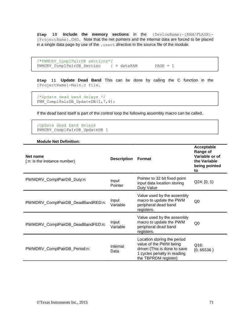
Texas Instruments Inc., 2015 71
Step 10 Include the memory sections in the {DeviceName}-{RAM/FLASH}-
{ProjectName}.CMD. Note that the net pointers and the internal data are forced to be placed
in a single data page by use of the .usect directive in the source file of the module.
/*PWMDRV_ComplPairDB sections*/
PWMDRV_ComplPairDB_Section : > dataRAM PAGE = 1
Step 11 Update Dead Band This can be done by calling the C function in the {ProjectName}-Main.c file.
/*Update dead band delays */
PWM_ComplPairDB_UpdateDB(1,7,4);
If the dead band itself is part of the control loop the following assembly macro can be called.
;Update dead band delays
PWMDRV_ComplPairDB_UpdateDB 1
Module Net Definition:
Net name (:n: is the instance number)
Description Format
Acceptable Range of Variable or of the Variable being pointed to
PWMDRV_ComplPairDB_Duty:n:
Input Pointer
Pointer to 32 bit fixed point input data location storing Duty Value
Q24: [0, 1)
PWMDRV_ComplPairDB_DeadBandRED:n: Input Variable
Value used by the assembly macro to update the PWM peripheral dead band registers.
Q0
PWMDRV_ComplPairDB_DeadBandFED:n: Input Variable
Value used by the assembly macro to update the PWM peripheral dead band registers.
Q0
PWMDRV_ComplPairDB_Period:n: Internal Data
Location storing the period value of the PWM being driven (This is done to save 1 cycles penalty in reading the TBPRDM register)
Q16: [0, 65536 )

Texas Instruments Inc., 2015 72
5.3.10 PWMDRV_DualUpDwnCnt : Dual PWM Driver , independent Duty on chA & ChB
Description: This hardware driver module, when used in conjunction with the corresponding PWM configuration file, drives a duty on PWM channel A, and PWM channel B dependent on the value of the input variables DutyA and DutyB.
PWMDRV_DualUpDwnCnt_Duty:n:A
PWM
PWMnA
PWMDRV_DualUpDwnCnt:n:
DutyA
PeriodDutyB PWMnB
PWMDRV_DualUpDwnCnt_Duty:n:B
Macro File: PWMDRV_DualUpDwnCnt.asm
Peripheral
Initialization File: PWM_DualUpDwnCnt_Cnf.c
Description: This assembly macro provides the interface between DP library net variables and the ePWM module on C28x. The macro converts the unsigned Q24 input, pointed to by the Net Pointers PWMDRV_DualUPDwnCnt_Duty:n:A and PWMDRV_DualUPDwnCnt_Duty:n:B into an unsigned Q0 number scaled by the PWM period value, and stores this value in the EPwmRegs:n:.CMPA and EPwmRegs:n:.CMPB such as to give independty duty cycle control on channel A and B of the PWM module.
PWMDRV_DualUpDwnCnt_Duty:n:A
PWMDRV_DualUpDwnCnt
ePWM:n:A
DutyA
ePWM:n:
CMPA
PWMDRV_DualUpDwnCnt_Period:n:
X
CMPBXPWMDRV_DualUpDwnCnt_Duty:n:B
DutyB
ePWM:n:B
This macro is used in conjunction with the peripheral configuration file PWM_DualUpDwnCnt_Cnf.c. The file defines the function
void PWM_DualUpDwnCnt_CNF(int16 n, int16 period, int16
mode, int16 phase)
where
n is the PWM peripheral number which is configured in up-down count mode
period is the maximum value of the PWM counter
mode determines whether the PWM is to be configured as slave or master,when configured as the master the TBSYNC signal is ignored by the PWM module.
Mode = 1 PWM configured as a master
Mode = 0 PWM configured as slave
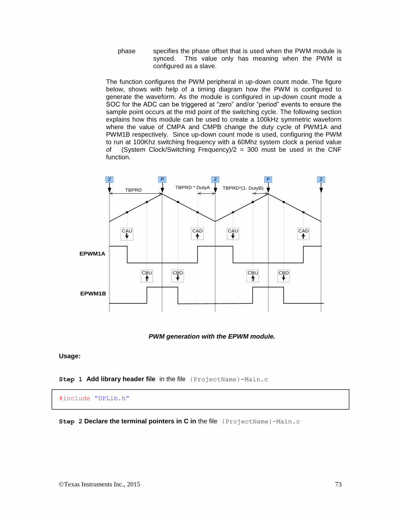
Texas Instruments Inc., 2015 73
phase specifies the phase offset that is used when the PWM module is synced. This value only has meaning when the PWM is configured as a slave.
The function configures the PWM peripheral in up-down count mode. The figure below, shows with help of a timing diagram how the PWM is configured to generate the waveform. As the module is configured in up-down count mode a SOC for the ADC can be triggered at “zero” and/or “period” events to ensure the sample point occurs at the mid point of the switching cycle. The following section explains how this module can be used to create a 100kHz symmetric waveform where the value of CMPA and CMPB change the duty cycle of PWM1A and PWM1B respectively. Since up-down count mode is used, configuring the PWM to run at 100Khz switching frequency with a 60Mhz system clock a period value of (System Clock/Switching Frequency)/2 = 300 must be used in the CNF function.
EPWM1A
CAU CAD
CBU CBD
CAU CAD
EPWM1B
CBDCBU
Z P Z ZP
TBPRDTBPRD * DutyA TBPRD*(1- DutyB)
PWM generation with the EPWM module.
Usage:
Step 1 Add library header file in the file {ProjectName}-Main.c
#include “DPLib.h”
Step 2 Declare the terminal pointers in C in the file {ProjectName}-Main.c

Texas Instruments Inc., 2015 74
// ---------------------------- DPLIB Net Pointers --------------------
// Declare net pointers that are used to connect the DP Lib Macros here
// and the data variables being used by the macros internally
//PWMDRV_DualUpDwnCnt - instance #1
extern volatile long *PWMDRV_DualUpDwnCnt_Duty1A;
extern volatile long *PWMDRV_DualUpDwnCnt_Duty1B;
extern volatile long PWMDRV_DualUpDwnCnt_Period1; // Optional
Step 3 Declare signal net nodes/ variables in C in the file {ProjectName}-Main.c
Note these signal nets name may change from system to system, there is no dependency on the signal net names to the module.
// ---------------------------- DPLIB Variables -----------------------
// Declare the net variables being used by the DP Lib Macro here
volatile long DutyA,DutyB;
Step 4 Call the Peripheral configuration function PWM_DualUpDwnCnt_CNF(int16 n,
int16 period, int16 mode, int16 phase) in {ProjectName}-Main.c, this function is
defined in PWM_ DualUpDwnCnt_Cnf.c. This file must be included manually into the project.
// Configure PWM1 for switching frequency 100Khz, @60Mhz CPU clock =>
// period = (60Mhz/(100Khz*2)) = 300; the 2 is because of up-down
// count mode; master mode; no phase offset
PWM_DualUpDwnCnt_CNF(1,300,1,0);
Step 5 “Call” the DPL_Init() to initialize the macros and “connect” the module terminals to
the Signal nets in “C” in {ProjectName}-Main.c. Also note the DPL_Init() function calls
the PWMDRV_DualUpDwnCnt_INIT function. This function initializes the value of
PWMDRV_DualUpDwnCnt_Period:n: with the period value of PWM being used. Hence the
value of PWM period must be stored before calling this function i.e. step 4 must be carried out before this step.
//----------Connect the macros to build a system-------------------
// Digital Power (DP) library initialisation
DPL_Init();
// PWMDRV_1ch block connections
PWMDRV_DualUpDwnCnt_Duty1A=&DutyA;
PWMDRV_DualUpDwnCnt_Duty1B=&DutyB;
// Initialize the net variables
DutyA=_IQ24(0.0);
DutyB=_IQ24(0.0);
Step 6 Add the ISR assembly file “{ProjectName}-DPL-ISR.asm” to the project.
Step 7 Include the macro’s assembly file in the {ProjectName}-DPL-ISR.asm
;Include files for the Power Library Macro's being used by the system
.include "PWMDRV_DualUpDwnCnt.asm"

Texas Instruments Inc., 2015 75
Step 8 Instantiate the INIT macro in assembly (this is one-time pass through code) inside the
C-callable DPL_Init() function which is defined in{ProjectName}-DPL-ISR.asm
;Macro Specific Initialization Functions
PWMDRV_DualUpDwnCnt_INIT 1 ; PWMDRV_1ch Initialization
Step 9 Call the run time macro in assembly inside the C-callable function DPL_ISR() which
is the looped or ISR code. The function is defined in{ProjectName}-DPL-ISR.asm
;”Call” the Run macro
PWMDRV_DualUpDwnCnt 1 ; Run PWMDRV_DualUpDwnCnt
Step 10 Include the memory sections in the {DeviceName}-{RAM/FLASH}-
{ProjectName}.CMD. Note that the net pointers and the internal data are forced to be placed
in a single data page by use of the .usect directive in the source file of the module.
/*PWMDRV_DualUpDwnCnt sections*/
PWMDRV_DualUpDwnCnt_Section : > dataRAM PAGE = 1
Module Net Definition:
Net name (:n: is the instance number)
Description Format
Acceptable Range of Variable or of the Variable being pointed to
PWMDRV_DualUpDwnCnt_Duty:n:A Input Pointer
Pointer to 32 bit fixed point input data location storing DutyA Value
Q24: [0, 1)
PWMDRV_DualUpDwnCnt_Duty:n:B
Input Pointer
Pointer to 32 bit fixed point input data location storing DutyB Value
Q24: [0, 1)
PWMDRV_ DualUpDwnCnt _Period:n: Internal Data
Location storing the period value of the PWM being driven (This is done to save 1 cycles penalty in reading the TBPRDM register)
Q16: [0, 65536 )

Texas Instruments Inc., 2015 76
5.3.11 PWMDRV_BuckBoost : Dual PWM Driver, independent Duty on chA & chB
Description: This hardware driver module, when used in conjunction with the corresponding PWM configuration file, drives a duty on PWM channel A, and a complimentary PWM on channel B with dead band, on two PWM modules. The power stage, described later, is such that Duty > 0.5 pu has a boost effect and Duty < 0.5 has a buck effect on output voltage to input voltage relation.
PWMDRV_BuckBoost_Duty:n: PWM
PWMnA
PWMDRV_BuckBoost:n,m:
DutyPWMnB
Period
PWMmA
PWMmB
Macro File: PWMDRV_BuckBoost.asm
Peripheral
Initialization File: PWM_BuckBoost_Cnf.c
Description: This assembly macro provides the interface between a DP library net variable and the ePWM module on C28x. The macro converts the unsigned Q24 input, pointed to by the Net Pointer PWMDRV_BuckBoost_Duty:n: into an unsigned Q0 number scaled by the PWM period value, and stores this value in the EPwmRegs:n:.CMPA and EPwmRegs:m:CMPA. The corresponding configuration file has the deadband module configured to output complimentary waveform on chB with a dead band.
This macro must be used in conjunction with the Peripheral configuration file PWM_BuckBoost _Cnf.c. The file defines the function
void PWM_BuckBoost_CNF(int16 n, int16 m, int16 period)
where
n is the PWM Peripheral number which is configured in up count mode
m is (n+1) always
Period is the maximum value of the PWM counter
The function configures the PWM peripheral in up count mode and configures the dead band submodule to output complimentary PWM waveforms. Periodic Sync pulse are also enabled between PWM module n and m. The falling edge delay is implemented by delaying the rising edge of the channel B using the dead band module in the PWM peripheral. The module outputs an active high duty on ChA of the PWM peripheral and a complementary on ChB.
The configuration function however does not set the deadband values, this is
done by calling the C function PWM_BuckBoost_UpdateDB function as
follows:
void PWM_BuckBoost_UpdateDB (int16 n, int16 DbRed, int16
DbFed)
where
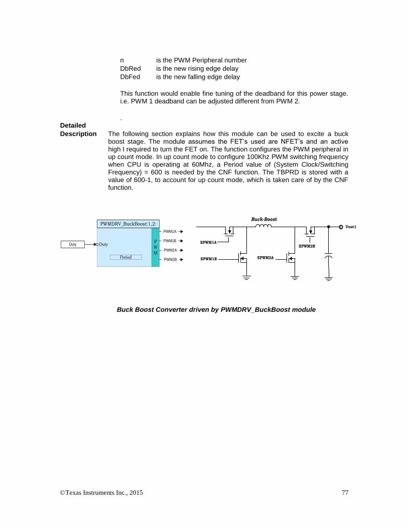
Texas Instruments Inc., 2015 77
n is the PWM Peripheral number
DbRed is the new rising edge delay
DbFed is the new falling edge delay
This function would enable fine tuning of the deadband for this power stage. i.e. PWM 1 deadband can be adjusted different from PWM 2.
. Detailed
Description The following section explains how this module can be used to excite a buck boost stage. The module assumes the FET’s used are NFET’s and an active high I required to turn the FET on. The function configures the PWM peripheral in up count mode. In up count mode to configure 100Khz PWM switching frequency when CPU is operating at 60Mhz, a Period value of (System Clock/Switching Frequency) = 600 is needed by the CNF function. The TBPRD is stored with a value of 600-1, to account for up count mode, which is taken care of by the CNF function.
EPWM1A
Vout1
Buck-Boost
Duty
EPWM1B
PWM
PWM1A
PWMDRV_BuckBoost:1,2:
DutyPWM1B
Period
PWM2A
PWM2B
EPWM2B
EPWM2A
Buck Boost Converter driven by PWMDRV_BuckBoost module

Texas Instruments Inc., 2015 78
EPWM1A
CB
A
Pulse Center
CA CACB
A
P
Z
P
Z
P
Z
EPWM1B
DbRedDbFed
EPWM2A
EPWM2B
DbRedDbFed
TimeBase
PWM1
TimeBase
PWM2
P P P
PWM Sync Pulse
PWM generation for BuckBoost PWM DRV Macro
Few thing to note about the power stage, the power stage can be used such that the FETs are switched as Buck Only and Boost Only, however these modes would put undue load on the Boot Strap for the high side driver. Also using two different PWM’s enables individual control of the deadbands which can enable finer tuning of the power stage. Also phase shifting and other modes are possible as well for the power stage when using two PWM modules.
Usage:
Step 1 Add library header file in the file {ProjectName}-Main.c
#include “DPLib.h”
Step 2 Declare the terminal pointers in C in the file {ProjectName}-Main.c
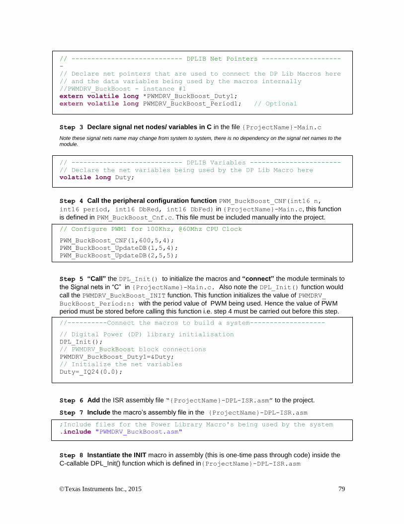
Texas Instruments Inc., 2015 79
// ---------------------------- DPLIB Net Pointers --------------------
-
// Declare net pointers that are used to connect the DP Lib Macros here
// and the data variables being used by the macros internally
//PWMDRV_BuckBoost - instance #1
extern volatile long *PWMDRV_BuckBoost_Duty1;
extern volatile long PWMDRV_BuckBoost_Period1; // Optional
Step 3 Declare signal net nodes/ variables in C in the file {ProjectName}-Main.c
Note these signal nets name may change from system to system, there is no dependency on the signal net names to the module.
// ---------------------------- DPLIB Variables -----------------------
// Declare the net variables being used by the DP Lib Macro here
volatile long Duty;
Step 4 Call the peripheral configuration function PWM_BuckBoost_CNF(int16 n,
int16 period, int16 DbRed, int16 DbFed) in {ProjectName}-Main.c, this function
is defined in PWM_BuckBoost_Cnf.c. This file must be included manually into the project.
// Configure PWM1 for 100Khz, @60Mhz CPU Clock
PWM_BuckBoost_CNF(1,600,5,4);
PWM_BuckBoost_UpdateDB(1,5,4);
PWM_BuckBoost_UpdateDB(2,5,5);
Step 5 “Call” the DPL_Init() to initialize the macros and “connect” the module terminals to
the Signal nets in “C” in {ProjectName}-Main.c. Also note the DPL_Init() function would
call the PWMDRV_BuckBoost_INIT function. This function initializes the value of PWMDRV_
BuckBoost_Period:n: with the period value of PWM being used. Hence the value of PWM
period must be stored before calling this function i.e. step 4 must be carried out before this step.
//----------Connect the macros to build a system-------------------
// Digital Power (DP) library initialisation
DPL_Init();
// PWMDRV_BuckBoost block connections
PWMDRV_BuckBoost_Duty1=&Duty;
// Initialize the net variables
Duty=_IQ24(0.0);
Step 6 Add the ISR assembly file “{ProjectName}-DPL-ISR.asm” to the project.
Step 7 Include the macro’s assembly file in the {ProjectName}-DPL-ISR.asm
;Include files for the Power Library Macro's being used by the system
.include "PWMDRV_BuckBoost.asm"
Step 8 Instantiate the INIT macro in assembly (this is one-time pass through code) inside the
C-callable DPL_Init() function which is defined in{ProjectName}-DPL-ISR.asm

Texas Instruments Inc., 2015 80
;Macro Specific Initialization Functions
PWMDRV_BuckBoost_INIT 1,2
Step 9 Call the run time macro in assembly inside the C-callable function DPL_ISR() which
is the looped or ISR code. The function is defined in{ProjectName}-DPL-ISR.asm
;”Call” the Run macro
PWMDRV_BuckBoost 1,2
Step 10 Include the memory sections in the {DeviceName}-{RAM/FLASH}-
{ProjectName}.CMD. Note that the net pointers and the internal data are forced to be placed
in a single data page by use of the .usect directive in the source file of the module.
/*PWMDRV_BuckBoost sections*/
PWMDRV_BuckBoost_Section : > dataRAM PAGE = 1
Module Net Definition:
Net name (:n: is the instance number)
Description Format
Acceptable Range of Variable or of the Variable being pointed to
PWMDRV_BuckBoost_Duty:n:
Input Pointer
Pointer to 32 bit fixed point input data location storing Duty Value
Q24: [0, 1)
PWMDRV_BuckBoost_Period:n: Internal Data
Location storing the period value of the PWM being driven (This is done to save 1 cycles penalty in reading the TBPRDM register)
Q16: [0, 65536 )

Texas Instruments Inc., 2015 81
5.3.12 PWMDRV_2ch_UpCnt : Dual PWM Driver, independent Duty on chA and chB
Description: This hardware driver module, when used in conjunction with the corresponding PWM configuration file, drives two independent duties on PWM channels A and B, dependent on the value of the input variables.
PWMDRV_2ch_UpCnt_Duty:n:APWM:n:ADutyA
Period
PWMDRV_2ch_UpCnt_Duty:n:BDutyB
PWM
PWMDRV_2ch_UpCnt:n:
PWM:n:B
Macro File: PWMDRV_2ch_UpCnt.asm
Peripheral
Initialization File: PWM_2ch_UpCnt_Cnf.c
Description: This assembly macro provides the interface between a DP library net variable and the ePWM module on C28x. The macro converts the unsigned Q24 input, pointed to by the net pointers PWMDRV_2ch_UpCnt_Duty:n:A and PWMDRV_2ch_UpCnt_Duty:n:B into unsigned Q0 numbers scaled by the PWM period value, and stores these values in the EPwmRegs:n:.CMPA and EPwmRegs:n:.CMPB registers, respectively. Which PWM Macro is driven and what period value is used for scaling is determined by the instance number of the macro i.e. :n:.
PWMDRV_2ch_UpCnt_Duty:n:B
PWMDRV_2ch_UpCnt_Duty:n:A
PWMDRV_2ch_UpCnt ePWM:n:A
DutyA XePWM:n:B
DutyB X
PWMDRV_2ch_UpCnt_Period:n:
ePWM:n:
CMPA
CMPA
This macro is used in conjunction with the peripheral configuration file PWM_2ch_UpCnt_Cnf.c. The file defines the function:
void PWM_2ch_UpCnt_CNF(int16 n, int16 period, int16 mode, int16 phase)
where:
n is the PWM Peripheral number which is configured in up count mode
Period is the maximum count value of the PWM timer
Mode determines whether the PWM is to be configured as slave or master, when configured as the master the TBSYNC signal is ignored by the PWM module.
Mode =1 PWM configured as a master
Mode = 0 PWM configured as slave
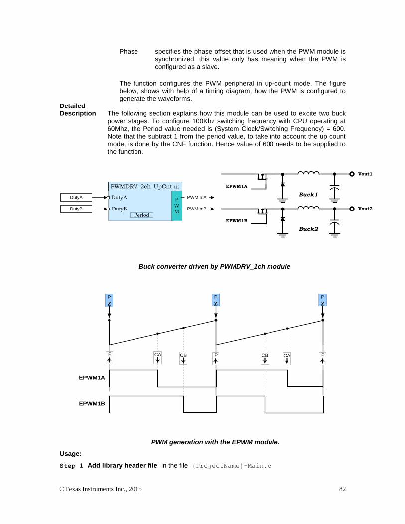
Texas Instruments Inc., 2015 82
Phase specifies the phase offset that is used when the PWM module is synchronized, this value only has meaning when the PWM is configured as a slave.
The function configures the PWM peripheral in up-count mode. The figure below, shows with help of a timing diagram, how the PWM is configured to generate the waveforms.
Detailed Description The following section explains how this module can be used to excite two buck
power stages. To configure 100Khz switching frequency with CPU operating at 60Mhz, the Period value needed is (System Clock/Switching Frequency) = 600. Note that the subtract 1 from the period value, to take into account the up count mode, is done by the CNF function. Hence value of 600 needs to be supplied to the function.
EPWM1A
Vout1
Buck1DutyA P
WM
PWM:n:A
PWMDRV_2ch_UpCnt:n:
DutyA
Period
DutyB PWM:n:BDutyB
EPWM1B
Vout2
Buck2
Buck converter driven by PWMDRV_1ch module
EPWM1A
CAP P PCA
P
Z
P
Z
P
Z
EPWM1B
CB CB
PWM generation with the EPWM module.
Usage:
Step 1 Add library header file in the file {ProjectName}-Main.c
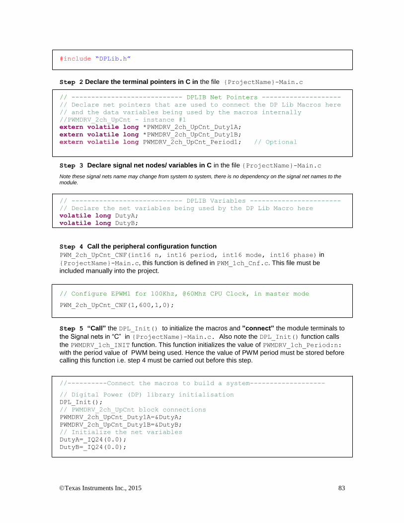
Texas Instruments Inc., 2015 83
#include “DPLib.h”
Step 2 Declare the terminal pointers in C in the file {ProjectName}-Main.c
// ---------------------------- DPLIB Net Pointers --------------------
// Declare net pointers that are used to connect the DP Lib Macros here
// and the data variables being used by the macros internally
//PWMDRV_2ch_UpCnt - instance #1
extern volatile long *PWMDRV_2ch_UpCnt_Duty1A;
extern volatile long *PWMDRV_2ch_UpCnt_Duty1B;
extern volatile long PWMDRV_2ch_UpCnt_Period1; // Optional
Step 3 Declare signal net nodes/ variables in C in the file {ProjectName}-Main.c
Note these signal nets name may change from system to system, there is no dependency on the signal net names to the module.
// ---------------------------- DPLIB Variables -----------------------
// Declare the net variables being used by the DP Lib Macro here
volatile long DutyA;
volatile long DutyB;
Step 4 Call the peripheral configuration function
PWM_2ch_UpCnt_CNF(int16 n, int16 period, int16 mode, int16 phase) in
{ProjectName}-Main.c, this function is defined in PWM_1ch_Cnf.c. This file must be
included manually into the project.
// Configure EPWM1 for 100Khz, @60Mhz CPU Clock, in master mode
PWM_2ch_UpCnt_CNF(1,600,1,0);
Step 5 “Call” the DPL_Init() to initialize the macros and ”connect” the module terminals to
the Signal nets in “C” in {ProjectName}-Main.c. Also note the DPL_Init() function calls
the PWMDRV_1ch_INIT function. This function initializes the value of PWMDRV_1ch_Period:n:
with the period value of PWM being used. Hence the value of PWM period must be stored before calling this function i.e. step 4 must be carried out before this step.
//----------Connect the macros to build a system-------------------
// Digital Power (DP) library initialisation
DPL_Init();
// PWMDRV_2ch_UpCnt block connections
PWMDRV_2ch_UpCnt_Duty1A=&DutyA;
PWMDRV_2ch_UpCnt_Duty1B=&DutyB;
// Initialize the net variables
DutyA=_IQ24(0.0);
DutyB=_IQ24(0.0);

Texas Instruments Inc., 2015 84
Step 6 Add the ISR assembly file “{ProjectName}-DPL-ISR.asm” to the project.
Step 7 Include the macro’s assembly file in the {ProjectName}-DPL-ISR.asm
;Include files for the Power Library Macro's being used by the system
.include "PWMDRV_2ch_UpCnt.asm"
Step 8 Instantiate the INIT macro in assembly (this is one-time pass through code) inside the
C-callable DPL_Init() function which is defined in{ProjectName}-DPL-ISR.asm
;Macro Specific Initialization Functions
PWMDRV_2ch_UpCnt_INIT 1 ; PWMDRV_2ch Initialization
Step 9 Call the run time macro in assembly inside the C-callable function DPL_ISR() which
is the looped or ISR code. The function is defined in{ProjectName}-DPL-ISR.asm
;”Call” the Run macro
PWMDRV_2ch_UpCnt 1 ; Run PWMDRV_2ch_UpCnt
;(Note EPWM1 is used for instance#1)
Step 10 Include the memory sections in the {DeviceName}-{RAM/FLASH}-
{ProjectName}.CMD. Note that the net pointers and the internal data are forced to be placed
in a single data page by use of the .usect directive in the source file of the module.
/*PWMDRV_2ch_UpCnt sections*/
PWMDRV_2ch_UpCnt_Section : > dataRAM PAGE = 1
Module Net Definition:
Net name (:n: is the instance number)
Description Format
Acceptable Range of Variable or of the Variable being pointed to
PWMDRV_2ch_UpCnt_Duty:n:A
Input Pointer
Pointer to 32 bit fixed point input data location storing DutyA Value
Q24: [0, 1)
PWMDRV_2ch_UpCnt_Duty:n:B
Input Pointer
Pointer to 32 bit fixed point input data location storing DutyB Value
Q24: [0, 1)
PWMDRV_2ch_UpCnt_Period:n: Internal Data
Location storing the period value of the PWM being driven (This is done to save 1 cycles penalty in reading the TBPRDM register)
Q16: [0, 65536 )

Texas Instruments Inc., 2015 85
5.3.13 PWMDRV_1ch_UpDwnCnt : PWM Driver, Duty on chA centered at zero
Description: This hardware driver module, when used in conjunction with the corresponding PWM configuration file, drives a duty on PWM channel A dependent on the value of the input variable DutyA. The waveform is centered at the zero value of the up down count time base of the PWM.
PWMDRV_1ch_UpDwnCnt_Duty:n:
PWM
PWMnA
PWMDRV_1ch_UpDwnCnt:n:
Duty
Period
Macro File: PWMDRV_1ch_UpDwnCnt.asm
Peripheral
Initialization File: PWM_1ch_UpDwnCnt_Cnf.c
Description: This assembly macro provides the interface between DP library net variables and the ePWM module on C28x. The macro converts the unsigned Q24 input, pointed to by the Net Pointer PWMDRV_1ch_UpDwnCnt_Duty:n:A into an unsigned Q0 number scaled by the PWM period value, and stores this value in the EPwmRegs:n:.CMPA such as to give duty cycle control on channel A of the PWM module.
PWMDRV_1ch_UpDwnCnt_Duty:n:
PWMDRV_1ch_UpDwnCnt
ePWM:n:A
Duty
ePWM:n:
CMPA
PWMDRV_1ch_UpDwnCnt_Period:n:
X
This macro is used in conjunction with the peripheral configuration file PWM_1ch_UpDwnCnt_Cnf.c. The file defines the function
void PWM_1ch_UpDwnCnt_CNF(int16 n, int16 period, int16 mode, int16 phase)
where
n is the PWM Peripheral number which is configured in up count mode
period is the maximum value of the PWM counter
mode determines whether the PWM is to be configured as slave or master,when configured as the master the TBSYNC signal is ignored by the PWM module.
Mode = 1 PWM configured as a master
Mode = 0 PWM configured as slave
phase specifies the phase offset that is used when the PWM module is synced. This value only has meaning when the PWM is configured as a slave.
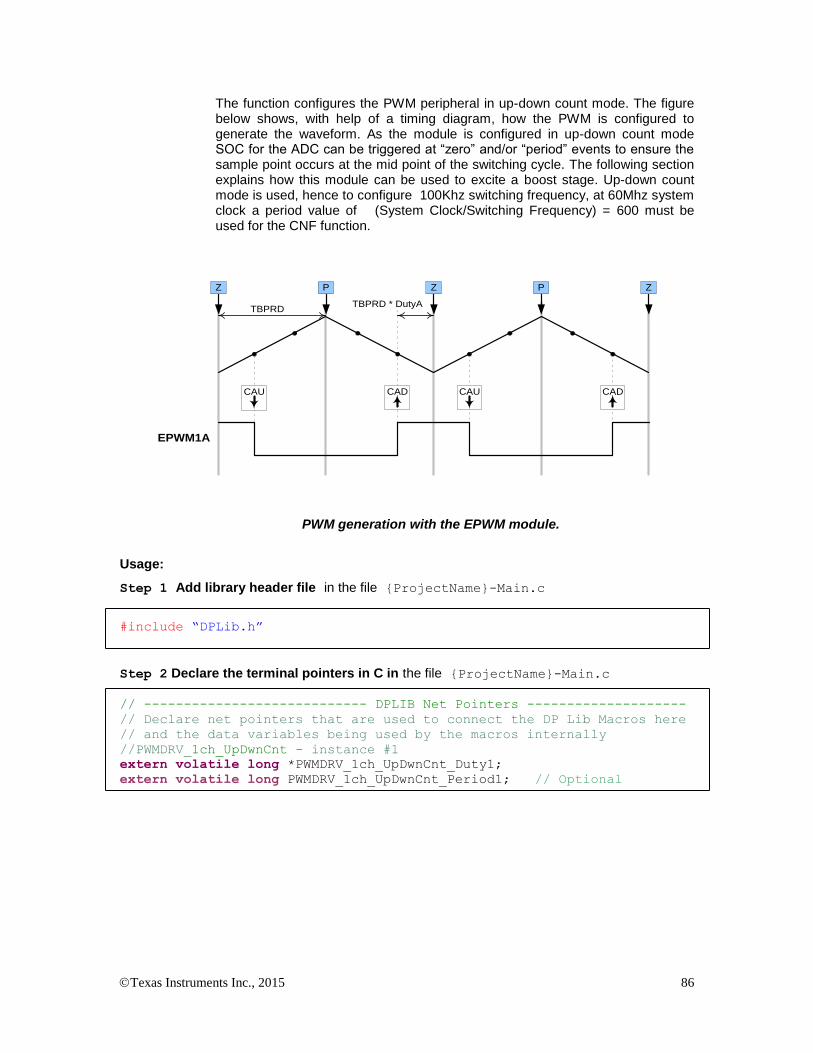
Texas Instruments Inc., 2015 86
The function configures the PWM peripheral in up-down count mode. The figure below shows, with help of a timing diagram, how the PWM is configured to generate the waveform. As the module is configured in up-down count mode SOC for the ADC can be triggered at “zero” and/or “period” events to ensure the sample point occurs at the mid point of the switching cycle. The following section explains how this module can be used to excite a boost stage. Up-down count mode is used, hence to configure 100Khz switching frequency, at 60Mhz system clock a period value of (System Clock/Switching Frequency) = 600 must be used for the CNF function.
EPWM1A
CAU CAD CAU CAD
Z P Z ZP
TBPRDTBPRD * DutyA
PWM generation with the EPWM module.
Usage:
Step 1 Add library header file in the file {ProjectName}-Main.c
#include “DPLib.h”
Step 2 Declare the terminal pointers in C in the file {ProjectName}-Main.c
// ---------------------------- DPLIB Net Pointers --------------------
// Declare net pointers that are used to connect the DP Lib Macros here
// and the data variables being used by the macros internally
//PWMDRV_1ch_UpDwnCnt - instance #1
extern volatile long *PWMDRV_1ch_UpDwnCnt_Duty1;
extern volatile long PWMDRV_1ch_UpDwnCnt_Period1; // Optional

Texas Instruments Inc., 2015 87
Step 3 Declare signal net nodes/ variables in C in the file {ProjectName}-Main.c
Note these signal nets name may change from system to system, there is no dependency on the signal net names to the module.
// ---------------------------- DPLIB Variables -----------------------
// Declare the net variables being used by the DP Lib Macro here
volatile long Duty;
Step 4 Call the Peripheral configuration function PWM_1ch_UpDwnCnt_CNF(int16 n,
int16 period, int16 mode, int16 phase) in {ProjectName}-Main.c, this function is
defined in PWM_ 1ch_UpDwnCnt_Cnf.c. This file must be included manually into the project.
// Configure PWM1 for switching frequency 100Khz, @60Mhz CPU clock =>
period = (60Mhz/100Khz) = 600
PWM_1ch_UpDwnCnt_CNF(1,600,1,0);
Step 5 “Call” the DPL_Init() to initialize the macros and “connect” the module terminals to
the Signal nets in “C” in {ProjectName}-Main.c. Also note the DPL_Init() function calls
the PWMDRV_1ch_UpDwnCnt_INIT function. This function initializes the value of
PWMDRV_1ch_UpDwnCnt_Period:n: with the period value of PWM being used. Hence the
value of PWM period must be stored before calling this function i.e. step 4 must be carried out before this step.
//----------Connect the macros to build a system-------------------
// Digital Power (DP) library initialisation
DPL_Init();
// PWMDRV_1ch_UpDwnCnt block connections
PWMDRV_1ch_UpDwnCnt_Duty1=&Duty;
// Initialize the net variables
Duty=_IQ24(0.0);
Step 6 Add the ISR assembly file “{ProjectName}-DPL-ISR.asm” to the project.
Step 7 Include the macro’s assembly file in the {ProjectName}-DPL-ISR.asm
;Include files for the Power Library Macro's being used by the system
.include "PWMDRV_1ch_UpDwnCnt.asm"
Step 8 Instantiate the INIT macro in assembly (this is one-time pass through code) inside the
C-callable DPL_Init() function which is defined in{ProjectName}-DPL-ISR.asm
;Macro Specific Initialization Functions
PWMDRV_1ch_UpDwnCnt_INIT 1 ; PWMDRV_1ch_UpDwnCnt Initialization
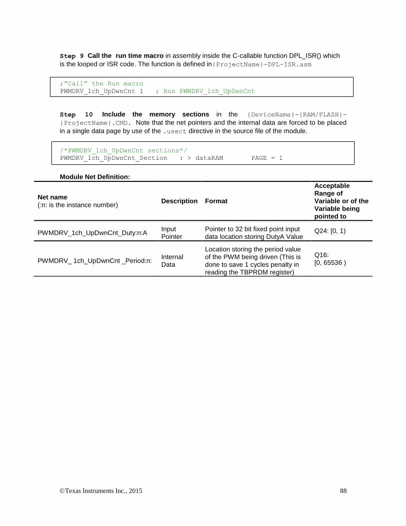
Texas Instruments Inc., 2015 88
Step 9 Call the run time macro in assembly inside the C-callable function DPL_ISR() which
is the looped or ISR code. The function is defined in{ProjectName}-DPL-ISR.asm
;”Call” the Run macro
PWMDRV_1ch_UpDwnCnt 1 ; Run PWMDRV_1ch_UpDwnCnt
Step 10 Include the memory sections in the {DeviceName}-{RAM/FLASH}-
{ProjectName}.CMD. Note that the net pointers and the internal data are forced to be placed
in a single data page by use of the .usect directive in the source file of the module.
/*PWMDRV_1ch_UpDwnCnt sections*/
PWMDRV_1ch_UpDwnCnt_Section : > dataRAM PAGE = 1
Module Net Definition:
Net name (:n: is the instance number)
Description Format
Acceptable Range of Variable or of the Variable being pointed to
PWMDRV_1ch_UpDwnCnt_Duty:n:A Input Pointer
Pointer to 32 bit fixed point input data location storing DutyA Value
Q24: [0, 1)
PWMDRV_ 1ch_UpDwnCnt _Period:n: Internal Data
Location storing the period value of the PWM being driven (This is done to save 1 cycles penalty in reading the TBPRDM register)
Q16: [0, 65536 )

Texas Instruments Inc., 2015 89
5.3.14 PWMDRV_1ch_UpDwnCntCompl : PWM Driver, Duty chA centered at period
Description: This hardware driver module, when used in conjunction with the corresponding PWM configuration file, drives a duty on PWM channel A dependent on the value of the input variable Duty. The waveform is centered at the period value of the up down count time base of the PWM.
PWMDRV_1ch_UpDwnCntCompl_Duty:n: PWM
PWMnA
PWMDRV_1ch_UpDwnCntCompl:n:
Duty
Period
Macro File: PWMDRV_1ch_UpDwnCntCompl.asm
Peripheral
Initialization File: PWM_1ch_UpDwnCntCompl_Cnf.c
Description: This assembly macro provides the interface between DP library net variables and the ePWM module on C28x. The macro converts the unsigned Q24 input, pointed to by the Net Pointer PWMDRV_1ch_UpDwnCntCompl_Duty:n: into an unsigned Q0 number scaled by the PWM period value, and stores this value in the EPwmRegs:n:.CMPA such as to give duty cycle control on channel A of the PWM module.
EPwmRegs:n:.CMPA=Period-Period*Duty
This macro is used in conjunction with the peripheral configuration file PWM_1ch_UpDwnCntCompl_Cnf.c. The file defines the function
void PWM_1ch_UpDwnCntCompl_CNF(int16 n, int16 period, int16 mode, int16 phase)
where
n is the PWM Peripheral number which is configured in up count mode
period is the maximum value of the PWM counter
mode determines whether the PWM is to be configured as slave or master,when configured as the master the TBSYNC signal is ignored by the PWM module.
Mode = 1 PWM configured as a master
Mode = 0 PWM configured as slave
phase specifies the phase offset that is used when the PWM module is synced. This value only has meaning when the PWM is configured as a slave.
The function configures the PWM peripheral in up-down count mode. The figure below shows, with help of a timing diagram, how the PWM is configured to generate the waveform. As the module is configured in up-down count mode SOC for the ADC can be triggered at “zero” and/or “period” events to ensure the sample point occurs at the mid point of the switching cycle. The following section
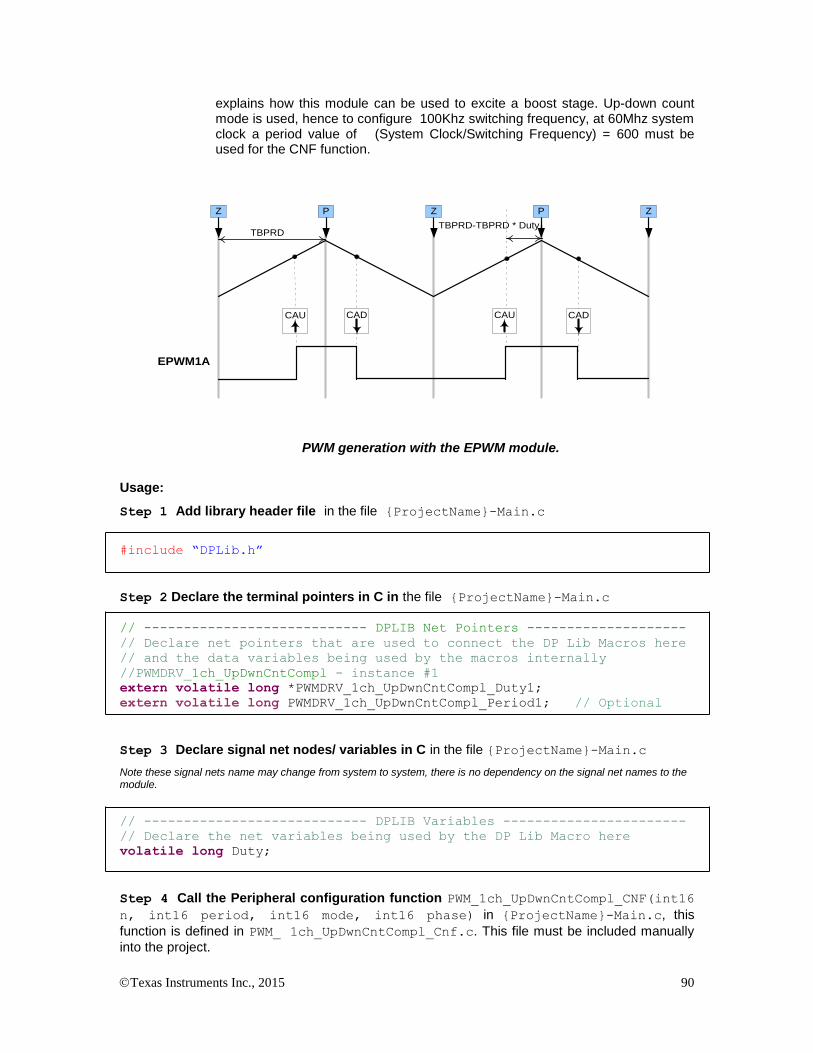
Texas Instruments Inc., 2015 90
explains how this module can be used to excite a boost stage. Up-down count mode is used, hence to configure 100Khz switching frequency, at 60Mhz system clock a period value of (System Clock/Switching Frequency) = 600 must be used for the CNF function.
EPWM1A
Z P Z ZP
TBPRDTBPRD-TBPRD * Duty
CAU CAD CAU CAD
PWM generation with the EPWM module.
Usage:
Step 1 Add library header file in the file {ProjectName}-Main.c
#include “DPLib.h”
Step 2 Declare the terminal pointers in C in the file {ProjectName}-Main.c
// ---------------------------- DPLIB Net Pointers --------------------
// Declare net pointers that are used to connect the DP Lib Macros here
// and the data variables being used by the macros internally
//PWMDRV_1ch_UpDwnCntCompl - instance #1
extern volatile long *PWMDRV_1ch_UpDwnCntCompl_Duty1;
extern volatile long PWMDRV_1ch_UpDwnCntCompl_Period1; // Optional
Step 3 Declare signal net nodes/ variables in C in the file {ProjectName}-Main.c
Note these signal nets name may change from system to system, there is no dependency on the signal net names to the module.
// ---------------------------- DPLIB Variables -----------------------
// Declare the net variables being used by the DP Lib Macro here
volatile long Duty;
Step 4 Call the Peripheral configuration function PWM_1ch_UpDwnCntCompl_CNF(int16
n, int16 period, int16 mode, int16 phase) in {ProjectName}-Main.c, this
function is defined in PWM_ 1ch_UpDwnCntCompl_Cnf.c. This file must be included manually
into the project.
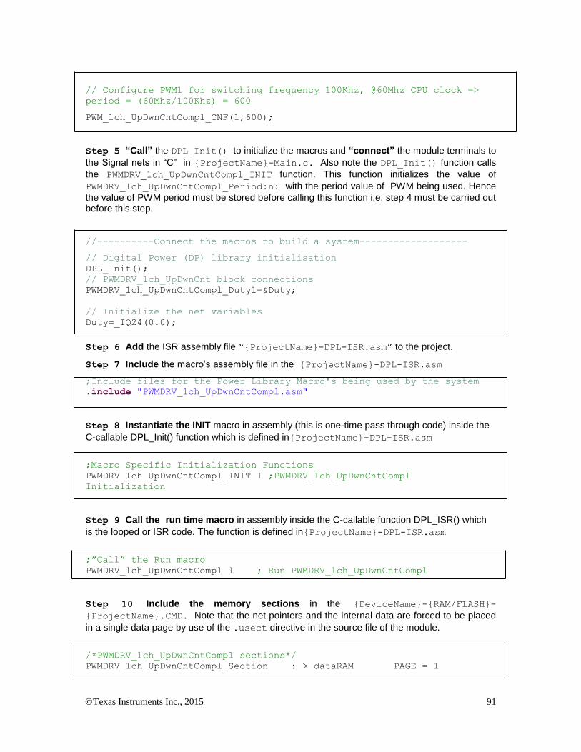
Texas Instruments Inc., 2015 91
// Configure PWM1 for switching frequency 100Khz, @60Mhz CPU clock =>
period = (60Mhz/100Khz) = 600
PWM_1ch_UpDwnCntCompl_CNF(1,600);
Step 5 “Call” the DPL_Init() to initialize the macros and “connect” the module terminals to
the Signal nets in “C” in {ProjectName}-Main.c. Also note the DPL_Init() function calls
the PWMDRV_1ch_UpDwnCntCompl_INIT function. This function initializes the value of
PWMDRV_1ch_UpDwnCntCompl_Period:n: with the period value of PWM being used. Hence
the value of PWM period must be stored before calling this function i.e. step 4 must be carried out before this step.
//----------Connect the macros to build a system-------------------
// Digital Power (DP) library initialisation
DPL_Init();
// PWMDRV_1ch_UpDwnCnt block connections
PWMDRV_1ch_UpDwnCntCompl_Duty1=&Duty;
// Initialize the net variables
Duty=_IQ24(0.0);
Step 6 Add the ISR assembly file “{ProjectName}-DPL-ISR.asm” to the project.
Step 7 Include the macro’s assembly file in the {ProjectName}-DPL-ISR.asm
;Include files for the Power Library Macro's being used by the system
.include "PWMDRV_1ch_UpDwnCntCompl.asm"
Step 8 Instantiate the INIT macro in assembly (this is one-time pass through code) inside the
C-callable DPL_Init() function which is defined in{ProjectName}-DPL-ISR.asm
;Macro Specific Initialization Functions
PWMDRV_1ch_UpDwnCntCompl_INIT 1 ;PWMDRV_1ch_UpDwnCntCompl
Initialization
Step 9 Call the run time macro in assembly inside the C-callable function DPL_ISR() which
is the looped or ISR code. The function is defined in{ProjectName}-DPL-ISR.asm
;”Call” the Run macro
PWMDRV_1ch_UpDwnCntCompl 1 ; Run PWMDRV_1ch_UpDwnCntCompl
Step 10 Include the memory sections in the {DeviceName}-{RAM/FLASH}-
{ProjectName}.CMD. Note that the net pointers and the internal data are forced to be placed
in a single data page by use of the .usect directive in the source file of the module.
/*PWMDRV_1ch_UpDwnCntCompl sections*/
PWMDRV_1ch_UpDwnCntCompl_Section : > dataRAM PAGE = 1
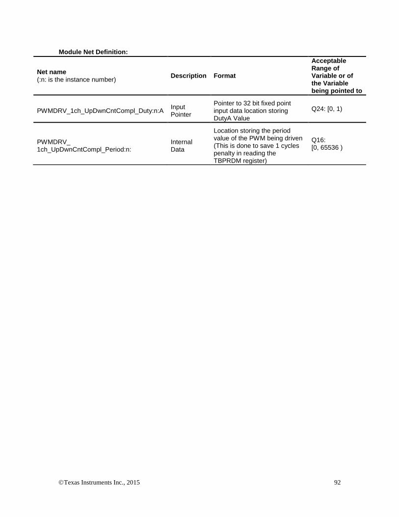
Texas Instruments Inc., 2015 92
Module Net Definition:
Net name (:n: is the instance number)
Description Format
Acceptable Range of Variable or of the Variable being pointed to
PWMDRV_1ch_UpDwnCntCompl_Duty:n:A Input Pointer
Pointer to 32 bit fixed point input data location storing DutyA Value
Q24: [0, 1)
PWMDRV_ 1ch_UpDwnCntCompl_Period:n:
Internal Data
Location storing the period value of the PWM being driven (This is done to save 1 cycles penalty in reading the TBPRDM register)
Q16: [0, 65536 )

Texas Instruments Inc., 2015 93
5.3.15 PWMDRV_PSFB_VMC_SR : PWM Driver for VMC PSFB Stage with SR
Description: This module controls the PWM generators to control a phase shifted full bridge (PSFB) in voltage mode control (VMC) and also drives synchronous rectifiers (SR), if used. Additionally, this module offers control over dead-band amounts for switching signals in the two legs of the bridge.
PWMDRV_PSFB_Phase:n:
PWMDRV_PSFB_DbAtoP:n:
PWMDRV_PSFB_DbPtoA:n:
PWMnA
PWMnB
PWMmA
PWMmB
PWM
PWMDRV_PSFB_VMC_SR:n,m,p:
Phase
dbAtoP
dbPtoA PWMpA
PWMpB
Macro File: PWMDRV_PSFB_VMC_SR.asm
Peripheral
Initialization File: PWM_PSFB_VMC_SR_Cnf.c
Description: This module forms the interface between the control software and the device PWM pins. The macro converts the unsigned Q24 input pointed to by the Net Pointer PWMDRV_PSFB_Phase:n: into an unsigned Q0 number scaled by the PWM period value, and stores this value in the EPwmRegs:m:.TBPHS and EPwmRegs:p:.TBPHS. The parameter inputs n and m to the macro module identify the PWM peripherals used to drive switches in the two legs while input p identifies the PWM peripherals used to drive the SR switches.
This macro is used in conjunction with the Peripheral configuration file PWM_PSFB_VMC_SR_CNF.c. The file defines the function
void PWMDRV_PSFB_VMC_SR_CNF(int16 n, int16 Period, int16
SR_Enable, int16 Comp1_Prot)
where
n is the master PWM peripheral configured for driving switches in one leg of the full bridge. PWM n+1 is configured to work with synch pulses from PWM n module and drives switches in the other leg. PWM n+3 drives SR switches if SR_Enable is 1.
Period is the maximum count value of the PWM timer
SR_Enable This enables drive to SR switches using PWM n+3 module. If a different PWM module is desired to be used for SR that module can be configured similar to PWM n+3 module configuration in this file. Note that if a different PWM module is selected for SR it should be a module number greater than n.
Comp1_Prot Enables catastrophic protection based on on-chip comparator1
and DAC.

Texas Instruments Inc., 2015 94
Detailed
Description The following section explains with help of a timing diagram, how the PWM is configured to generate waveforms to drive a PSFB power stage. In up count mode to configure 100Khz switching frequency for the PWM when CPU is operating at 60Mhz, the Period value needed is (System Clock/Switching Frequency) = 600.
PWMDRV_PSFB_Phase:n:
PWMDRV_PSFB_DbAtoP:n:
PWMDRV_PSFB_DbPtoA:n:
PWMnA
PWMnB
PWMmA
PWMmB
PWM
PWMDRV_PSFB_VMC_SR:n,m,p:
Phase
dbAtoP
dbPtoA PWMpA
PWMpB
VDC_bus VOUT
PWM:n:A
PWM:n:B
PWM:m:A
PWM:m:B
“AtoP Leg”
PWM:p:A PWM:p:B
“PtoA Leg”
Full bridge power converter
Power
Phase
DbAtoPPWM:n:A
PWM:n:B
PWM:m:A
PWM:m:B
phase
AtoP leg
dead-band
PtoA leg
dead-band
50% duty
DbAtoP
DbPtoA
DbPtoA
PRD CAD
CBU ZRO
CMPAp = TBPRDm – TBPHSm, CMPBp = TBPHSm = TBPHSm
SR Mode 2SR Mode 1
PRD CAD
Abbreviations:
CMPA/Bx – Compare A/B register value for PWM module ‘x’
CAU – Time base counter = Compare A event when the timer is counting UP
CAD – Time base counter = Compare A event when the timer is counting DOWN
PRD – Time base counter = Period event
ZRO – Time base counter = Zero event
ZRO
PWM:p:A
PWM:p:B
Phase shifted PWM generation with the EPWM module.
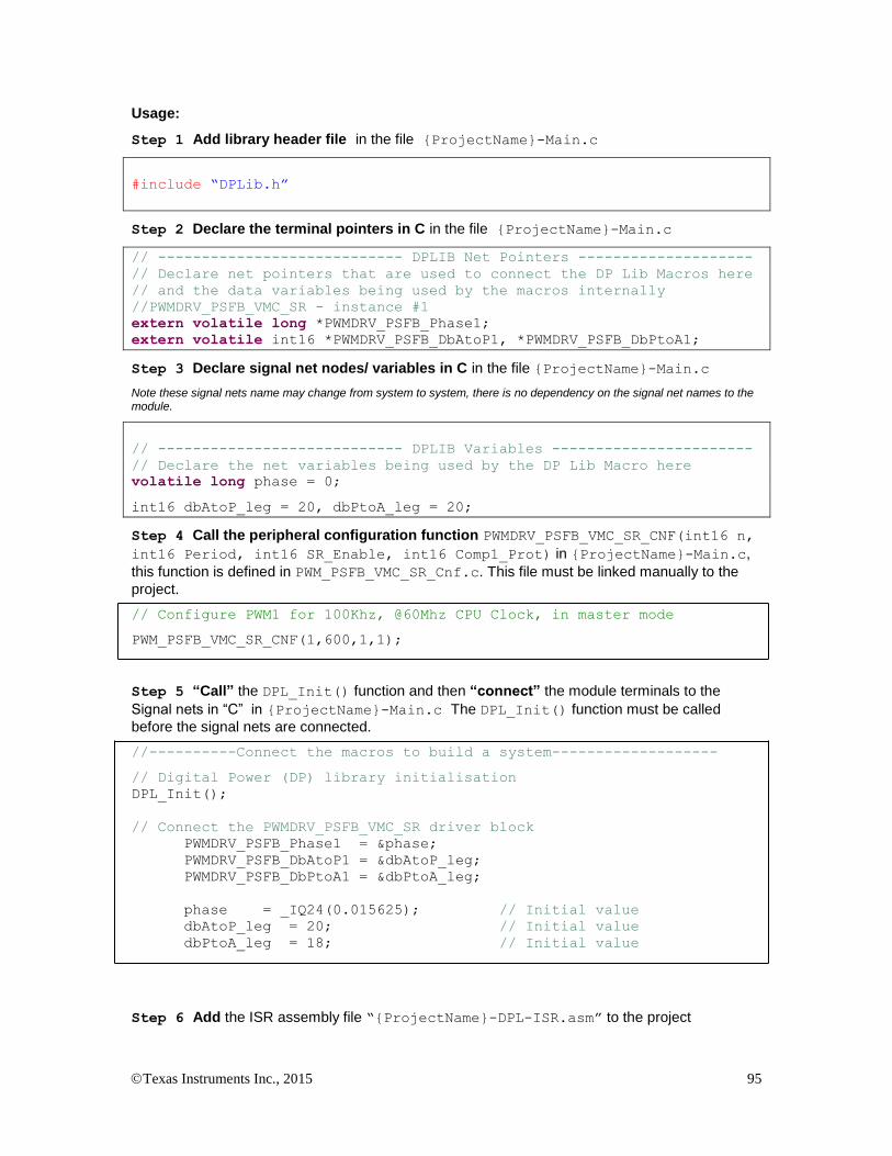
Texas Instruments Inc., 2015 95
Usage:
Step 1 Add library header file in the file {ProjectName}-Main.c
#include “DPLib.h”
Step 2 Declare the terminal pointers in C in the file {ProjectName}-Main.c
// ---------------------------- DPLIB Net Pointers --------------------
// Declare net pointers that are used to connect the DP Lib Macros here
// and the data variables being used by the macros internally
//PWMDRV_PSFB_VMC_SR - instance #1
extern volatile long *PWMDRV_PSFB_Phase1;
extern volatile int16 *PWMDRV_PSFB_DbAtoP1, *PWMDRV_PSFB_DbPtoA1;
Step 3 Declare signal net nodes/ variables in C in the file {ProjectName}-Main.c
Note these signal nets name may change from system to system, there is no dependency on the signal net names to the module.
// ---------------------------- DPLIB Variables -----------------------
// Declare the net variables being used by the DP Lib Macro here
volatile long phase = 0;
int16 dbAtoP_leg = 20, dbPtoA_leg = 20;
Step 4 Call the peripheral configuration function PWMDRV_PSFB_VMC_SR_CNF(int16 n,
int16 Period, int16 SR_Enable, int16 Comp1_Prot) in {ProjectName}-Main.c,
this function is defined in PWM_PSFB_VMC_SR_Cnf.c. This file must be linked manually to the
project.
// Configure PWM1 for 100Khz, @60Mhz CPU Clock, in master mode
PWM_PSFB_VMC_SR_CNF(1,600,1,1);
Step 5 “Call” the DPL_Init() function and then “connect” the module terminals to the
Signal nets in “C” in {ProjectName}-Main.c The DPL_Init() function must be called
before the signal nets are connected.
//----------Connect the macros to build a system-------------------
// Digital Power (DP) library initialisation
DPL_Init();
// Connect the PWMDRV_PSFB_VMC_SR driver block
PWMDRV_PSFB_Phase1 = &phase;
PWMDRV_PSFB_DbAtoP1 = &dbAtoP_leg;
PWMDRV_PSFB_DbPtoA1 = &dbPtoA_leg;
phase = _IQ24(0.015625); // Initial value
dbAtoP_leg = 20; // Initial value
dbPtoA_leg = 18; // Initial value
Step 6 Add the ISR assembly file “{ProjectName}-DPL-ISR.asm” to the project

Texas Instruments Inc., 2015 96
Step 7 Include the macro’s assembly file in the {ProjectName}-DPL-ISR.asm
;Include files for the Power Library Macro's being used by the system
.include "PWMDRV_PSFB_VMC_SR.asm"
Step 8 Instantiate the INIT macro in assembly (this is one-time pass through code) inside the
C-callable DPL_Init() function which is defined in{ProjectName}-DPL-ISR.asm. Note when
instantiating n, m and p need to be passed as arguments. ;Macro Specific Initialization Functions PWMDRV_PSFB_VMC_SR_INIT 1,2,4 ; Initialization
Step 9 Call the run time macro in assembly inside the C-callable function DPL_ISR() which
is the looped or ISR code. The function is defined in{ProjectName}-DPL-ISR.asm. Note
when calling the run time macro n, m and p need to be passed as arguments.
;”Call” the Run macro
PWMDRV_PSFB_VMC_SR 1,2,4 ; Run PWMDRV_PSFB_VMC_SR
Step 10 Include the memory sections in the {DeviceName}-{RAM/FLASH}-
{ProjectName}.CMD. Note that the net pointers and the internal data are forced to be placed
in a single data page by use of the .usect directive in the source file of the module.
/*PWMDRV_PSFB sections*/
PWMDRV_PSFB_Section : > dataRAM PAGE = 1
Module Net Definition:
Net name (:n: is the instance number)
Description Format Acceptable Range of Variable or of the Variable being pointed to
PWMDRV_PSFB_Phase:n:
Input Pointer
Pointer to 32 bit fixed point input data location to Phase value
Q24(0,1)
PWMDRV_PSFB_DbAtoP:n: Input
Pointer
Pointer to 32 bit fixed point input data location to Dead Band Value for Left Leg
Q0
PWMDRV_PSFB_DbPtoA:n: Input Pointer
Pointer to 32 bit fixed point input data location to Dead Band Value for Right Leg
Q0
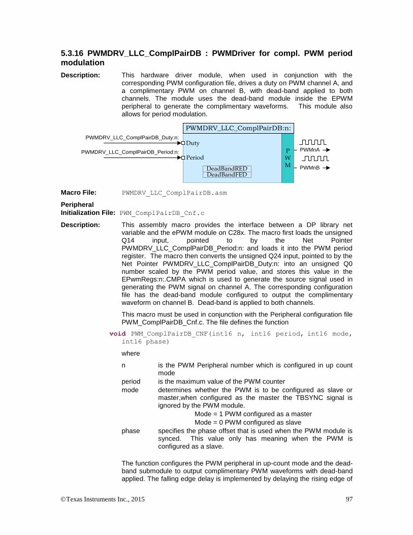
Texas Instruments Inc., 2015 97
5.3.16 PWMDRV_LLC_ComplPairDB : PWMDriver for compl. PWM period modulation
Description: This hardware driver module, when used in conjunction with the corresponding PWM configuration file, drives a duty on PWM channel A, and a complimentary PWM on channel B, with dead-band applied to both channels. The module uses the dead-band module inside the EPWM peripheral to generate the complimentary waveforms. This module also allows for period modulation.
PWMDRV_LLC_ComplPairDB_Duty:n:
PWM
PWMnA
PWMDRV_LLC_ComplPairDB:n:
Duty
DeadBandRED PWMnB
DeadBandFED
PWMDRV_LLC_ComplPairDB_Period:n:Period
Macro File: PWMDRV_LLC_ComplPairDB.asm
Peripheral
Initialization File: PWM_ComplPairDB_Cnf.c
Description: This assembly macro provides the interface between a DP library net variable and the ePWM module on C28x. The macro first loads the unsigned Q14 input, pointed to by the Net Pointer PWMDRV_LLC_ComplPairDB_Period:n: and loads it into the PWM period register. The macro then converts the unsigned Q24 input, pointed to by the Net Pointer PWMDRV_LLC_ComplPairDB_Duty:n: into an unsigned Q0 number scaled by the PWM period value, and stores this value in the EPwmRegs:n:.CMPA which is used to generate the source signal used in generating the PWM signal on channel A. The corresponding configuration file has the dead-band module configured to output the complimentary waveform on channel B. Dead-band is applied to both channels.
This macro must be used in conjunction with the Peripheral configuration file PWM_ComplPairDB_Cnf.c. The file defines the function
void PWM_ComplPairDB_CNF(int16 n, int16 period, int16 mode, int16 phase)
where
n is the PWM Peripheral number which is configured in up count mode
period is the maximum value of the PWM counter
mode determines whether the PWM is to be configured as slave or master,when configured as the master the TBSYNC signal is ignored by the PWM module.
Mode = 1 PWM configured as a master
Mode = 0 PWM configured as slave
phase specifies the phase offset that is used when the PWM module is synced. This value only has meaning when the PWM is configured as a slave.
The function configures the PWM peripheral in up-count mode and the dead-band submodule to output complimentary PWM waveforms with dead-band applied. The falling edge delay is implemented by delaying the rising edge of

Texas Instruments Inc., 2015 98
the channel B using the dead-band module in the PWM peripheral. The module outputs an active high duty on ChA of the PWM peripheral and a complementary active low duty on ChB.
The configuration function only configures the dead-band at initialization time. However, it may be needed to change the dead-band during operation. This can be done by calling the function
void PWM_ComplPairDB_UpdateDB (int16 n, int16 DbRed, int16
DbFed)
where
n is the PWM Peripheral number
DbRed is the new rising edge delay
DbFed is the new falling edge delay
Alternatively, an assembly macro is provided to update the dead-band if the update needs to be done at a faster rate, inside the ISR. The dead-band
update assembly macro, PWMDRV_LLC_ComplPairDB_UpdateDB,
updates the dead-band registers with values stored in the macro variables
PWMDRV_LLC_ComplPairDB_DeadBandRED:n: and PWMDRV_
LLC_ComplPairDB_DeadBandFED:n:
Detailed
Description The following section explains how this module can be used to excite a Resonant LLC power stage which uses two NFET’s. (Please note this module is specific to Resonant LLC power stage using NPN transistors only). The function configures the PWM peripheral in up-count mode. In order to configure a 100Khz switching frequency for the PWM in up-count mode when CPU is operating at 60Mhz, the Period value needed is (System Clock/Switching Frequency) = 600 needs to be provided to the CNF function. The TBPRD is stored with a value of 600-1, to take the up-count mode into account by the CNF function itself.
Duty:n:
PWM
PWMnA
PWMDRV_LLC_ComplPairDB:n:
Duty
DeadBandRED PWMnB
DeadBandFED
Period:n:Period
EPWM1A
EPWM1B
Vout
Resonant LLC
Resonant LLC converter driven by PWMDRV_LLC_ComplPairDB module

Texas Instruments Inc., 2015 99
EPWM1A
CB
A
Pulse Center
CAZ Z ZCACB
A
P
Z
P
Z
P
Z
EPWM1B
DbRedDbFed
PWM generation for PWMDRV_LLC_CompPairDB Macro
Usage:
Step 1 Add library header file in the file {ProjectName}-Main.c
#include “DPLib.h”
Step 2 Declare the terminal pointers in C in the file {ProjectName}-Main.c
// ---------------------------- DPLIB Net Pointers --------------------
// Declare net pointers that are used to connect the DP Lib Macros here
// and the data variables being used by the macros internally
//PWMDRV_LLC_ComplPairDB - instance #1
extern volatile long *PWMDRV_LLC_ComplPairDB_Duty1;
extern volatile long *PWMDRV_LLC_ComplPairDB_Period1;
extern volatile int16 PWMDRV_LLC_ComplPairDB_DeadBandRED1; //Optional
extern volatile int16 PWMDRV_LLC_ComplPairDB_DeadBandFED1; //Optional
Step 3 Declare signal net nodes/ variables in C in the file {ProjectName}-Main.c
Note these signal nets name may change from system to system, there is no dependency on the signal net names to the module.
// ---------------------------- DPLIB Variables -----------------------
// Declare the net variables being used by the DP Lib Macro here
volatile long Duty;
volatile long Period;
Step 4 Call the peripheral configuration function PWM_ComplPairDB_CNF(int16 n,
int16 period, int16 mode, int16 phase) in {ProjectName}-Main.c, this function is
defined in PWM_ComplPairDB_Cnf.c. This file must be included manually into the project. The

Texas Instruments Inc., 2015 100
following code snippet configures PWM1 in Up Count mode and configures the dead band to be 5
and 4 cycles for the rising edge and falling edge respectively.
// Configure PWM1 for 100Khz, @60Mhz CPU Clock
PWM_ComplPairDB_CNF(1,600, 1, 0);
PWM_ComplPairDB_UpdateDB(1,5,4);
Step 5 “Call” the DPL_Init() to initialize the macros and “connect” the module terminals to
the Signal nets in “C” in {ProjectName}-Main.c. Also note the DPL_Init() function would
call the PWMDRV_LLC_ComplPairDB_INIT function.
//----------Connect the macros to build a system-------------------
// Digital Power (DP) library initialisation
DPL_Init();
// PWMDRV_LLC_ComplPairDB block connections
PWMDRV_LLC_ComplPairDB_Duty1=&Duty;
PWMDRV_LLC_ComplPairDB_Period1=&Period;
// Initialize the net variables
Duty=_IQ24(0.5);
Step 6 Add the ISR assembly file “{ProjectName}-DPL-ISR.asm” to the project.
Step 7 Include the macro’s assembly file in the {ProjectName}-DPL-ISR.asm
;Include files for the Power Library Macro's being used by the system
.include "PWMDRV_LLC_ComplPairDB.asm"
Step 8 Instantiate the INIT macro in assembly (this is one-time pass through code) inside the
C-callable DPL_Init() function which is defined in{ProjectName}-DPL-ISR.asm
;Macro Specific Initialization Functions
PWMDRV_LLC_ComplPairDB_INIT 1
Step 9 Call the run time macro in assembly inside the C-callable function DPL_ISR() which
is the looped or ISR code. The function is defined in{ProjectName}-DPL-ISR.asm
;”Call” the Run macro
PWMDRV_LLC_ComplPairDB 1
Step 10 Include the memory sections in the {DeviceName}-{RAM/FLASH}-
{ProjectName}.CMD. Note that the net pointers and the internal data are forced to be placed
in a single data page by use of the .usect directive in the source file of the module.
/*PWMDRV_LLC_ComplPairDB sections*/
PWMDRV_LLC_ComplPairDB_Section : > dataRAM PAGE = 1
Step 11 Update Dead-Band This can be done by calling the C function in the {ProjectName}-Main.c file.
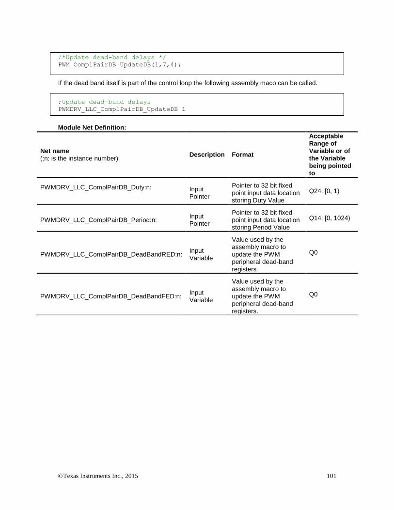
Texas Instruments Inc., 2015 101
/*Update dead-band delays */
PWM_ComplPairDB_UpdateDB(1,7,4);
If the dead band itself is part of the control loop the following assembly maco can be called.
;Update dead-band delays
PWMDRV_LLC_ComplPairDB_UpdateDB 1
Module Net Definition:
Net name (:n: is the instance number)
Description Format
Acceptable Range of Variable or of the Variable being pointed to
PWMDRV_LLC_ComplPairDB_Duty:n:
Input Pointer
Pointer to 32 bit fixed point input data location storing Duty Value
Q24: [0, 1)
PWMDRV_LLC_ComplPairDB_Period:n: Input Pointer
Pointer to 32 bit fixed point input data location storing Period Value
Q14: [0, 1024)
PWMDRV_LLC_ComplPairDB_DeadBandRED:n: Input Variable
Value used by the assembly macro to update the PWM peripheral dead-band registers.
Q0
PWMDRV_LLC_ComplPairDB_DeadBandFED:n: Input Variable
Value used by the assembly macro to update the PWM peripheral dead-band registers.
Q0

Texas Instruments Inc., 2015 102
5.3.17 PWMDRV_LLC_1ch_UpCntDB : PWM Driver for chA PWM edge shift, period mode
Description: This hardware driver module, when used in conjunction with the corresponding PWM configuration file, drives a duty on PWM channel A, with edge shifting. The module uses the dead-band module inside the EPWM peripheral along with software to generate the rising edge shift (RES) and falling edge shift (FES). This module also allows for period modulation.
PWMDRV_LLC_1ch_UpCntDB_Duty:n:
PWM
PWMnA
PWMDRV_LLC_1ch_UpCntDB:n:
Duty
DeadBandREDDeadBandFED
PWMDRV_LLC_1ch_UpCntDB_Period:n:Period
Macro File: PWMDRV_LLC_1ch_UpCntDB.asm
Peripheral
Initialization File: PWM_1ch_UpCntDB_Cnf.c
Description: This assembly macro provides the interface between a DP library net variable and the ePWM module on C28x. The macro first loads the unsigned Q14 input, pointed to by the Net Pointer PWMDRV_LLC_1ch_UpCntDB_Period:n: and loads it into the PWM period register. The macro then converts the unsigned Q24 input, pointed to by the Net Pointer PWMDRV_LLC_1ch_UpCntDB_Duty:n: into an unsigned Q0 number scaled by the PWM period value, and stores this value in the EPwmRegs:n:.CMPA. The falling edge is advanced through software by the value specified in EPwmRegs:n:.DBFED by subtracting that value from the EPwmRegs:n:.CMPA register. The rising edge is delayed by the value specified in EPwmRegs:n:.DBRED using the dead-band module.
This macro must be used in conjunction with the Peripheral configuration file PWM_1ch_UpCntDB_Cnf.c. The file defines the function
void PWM_1ch_UpCntDB_CNF(int16 n, int16 period, int16 mode, int16 phase)
where
n is the PWM Peripheral number which is configured in up count mode
period is the maximum value of the PWM counter
mode determines whether the PWM is to be configured as slave or master,when configured as the master the TBSYNC signal is ignored by the PWM module.
Mode = 1 PWM configured as a master
Mode = 0 PWM configured as slave
phase specifies the phase offset that is used when the PWM module is synced. This value only has meaning when the PWM is configured as a slave.
The function configures the PWM peripheral in up-count mode and the dead-band submodule to PWM chA with dead-band applied. The module outputs an active high duty on ChA of the PWM peripheral.

Texas Instruments Inc., 2015 103
The configuration function only configures the dead-band at initialization time. However, it may be needed to change the dead-band during operation. This can be done by calling the function
void PWM_1ch_UpCntDB_UpdateDB (int16 n, int16 DbRed, int16
DbFed)
where
n is the PWM Peripheral number
DbRed is the new rising edge delay
DbFed is the new falling edge delay
Alternatively, an assembly macro is provided to update the dead-band if the update needs to be done at a faster rate, inside the ISR. The dead-band
update assembly macro, PWMDRV_LLC_1ch_UpCntDB_UpdateDB,
updates the dead-band registers with values stored in the macro variables
PWMDRV_LLC_1ch_UpCntDB_DeadBandRED:n: and PWMDRV_
LLC_1ch_UpCntDB_DeadBandFED:n:
. Detailed
Description The following section explains how this module can be used to excite one of the Synchronous Rectifier legs of an LLC Resonant power stage. (Please note this module is specific to using NPN transistors only). The function configures the PWM peripheral in up-count mode. In order to configure a 100Khz switching frequency for the PWM in up-count mode when CPU is operating at 60Mhz, the Period value needed is (System Clock/Switching Frequency) = 600 needs to be provided to the CNF function. The TBPRD is stored with a value of 600-1, to take the up-count mode into account by the CNF function itself.
Duty:n:
PWM
PWMnA
PWMDRV_LLC_1ch_UpCntDB:n:
Duty
DeadBandREDDeadBandFED
Period:n:Period
LLC Resonant
PWM2A
Vin Vout
LLC Resonant converter Synchronous Rectifier leg driven by PWMDRV_LLC_1ch_UpCntDB module

Texas Instruments Inc., 2015 104
Source
CB
A
Pulse Center
CAZ Z ZCACB
A
P
Z
P
Z
P
Z
EPWM2A
DbRed
(RES)FES
PWM generation for PWMDRV_LLC_1ch_UpCntDB Macro
Usage:
Step 1 Add library header file in the file {ProjectName}-Main.c
#include “DPLib.h”
Step 2 Declare the terminal pointers in C in the file {ProjectName}-Main.c
// ---------------------------- DPLIB Net Pointers --------------------
// Declare net pointers that are used to connect the DP Lib Macros here
// and the data variables being used by the macros internally
//PWMDRV_LLC_1ch_UpCntDB - instance #1
extern volatile long *PWMDRV_LLC_1ch_UpCntDB_Duty1;
extern volatile long *PWMDRV_LLC_1ch_UpCntDB_Period1;
extern volatile int16 PWMDRV_LLC_1ch_UpCntDB_DeadBandRED1; //Optional
extern volatile int16 PWMDRV_LLC_1ch_UpCntDB_DeadBandFED1; //Optional
Step 3 Declare signal net nodes/ variables in C in the file {ProjectName}-Main.c
Note these signal nets name may change from system to system, there is no dependency on the signal net names to the module.
// ---------------------------- DPLIB Variables -----------------------
// Declare the net variables being used by the DP Lib Macro here
volatile long Duty;
volatile long Period;

Texas Instruments Inc., 2015 105
Step 4 Call the peripheral configuration function PWM_1ch_UpCntDB_CNF(int16 n,
int16 period, int16 mode, int16 phase) in {ProjectName}-Main.c, this function is
defined in PWM_1ch_UpCntDB_Cnf.c. This file must be included manually into the project. The
following code snippet configures PWM1 in Up Count mode and configures the dead band to be 5
and 4 cycles for the rising edge and falling edge respectively.
// Configure PWM1 for 100Khz, @60Mhz CPU Clock
PWM_1ch_UpCntDB_CNF(1,600, 1, 0);
PWM_1ch_UpCntDB_UpdateDB(1,5,4);
Step 5 “Call” the DPL_Init() to initialize the macros and “connect” the module terminals to
the Signal nets in “C” in {ProjectName}-Main.c. Also note the DPL_Init() function would
call the PWMDRV_LLC_1ch_UpCntDB_INIT function.
//----------Connect the macros to build a system-------------------
// Digital Power (DP) library initialisation
DPL_Init();
// PWMDRV_LLC_1ch_UpCntDB block connections
PWMDRV_LLC_1ch_UpCntDB_Duty1=&Duty;
PWMDRV_LLC_1ch_UpCntDB_Period1=&Period;
// Initialize the net variables
Duty=_IQ24(0.5);
Step 6 Add the ISR assembly file “{ProjectName}-DPL-ISR.asm” to the project.
Step 7 Include the macro’s assembly file in the {ProjectName}-DPL-ISR.asm
;Include files for the Power Library Macro's being used by the system
.include "PWMDRV_LLC_1ch_UpCntDB.asm"
Step 8 Instantiate the INIT macro in assembly (this is one-time pass through code) inside the
C-callable DPL_Init() function which is defined in{ProjectName}-DPL-ISR.asm
;Macro Specific Initialization Functions
PWMDRV_LLC_1ch_UpCntDB_INIT 1
Step 9 Call the run time macro in assembly inside the C-callable function DPL_ISR() which
is the looped or ISR code. The function is defined in{ProjectName}-DPL-ISR.asm
;”Call” the Run macro
PWMDRV_LLC_1ch_UpCntDB 1

Texas Instruments Inc., 2015 106
Step 10 Include the memory sections in the {DeviceName}-{RAM/FLASH}-
{ProjectName}.CMD. Note that the net pointers and the internal data are forced to be placed
in a single data page by use of the .usect directive in the source file of the module.
/*PWMDRV_LLC_1ch_UpCntDB sections*/
PWMDRV_LLC_1ch_UpCntDB_Section : > dataRAM PAGE = 1
Step 11 Update Dead-Band This can be done by calling the C function in the {ProjectName}-Main.c file.
/*Update dead-band delays */
PWM_1ch_UpCntDB_UpdateDB(1,7,4);
If the dead band itself is part of the control loop the following assembly maco can be called.
;Update dead-band delays
PWMDRV_LLC_1ch_UpCntDB_UpdateDB 1
Module Net Definition:
Net name (:n: is the instance number)
Description Format
Acceptable Range of Variable or of the Variable being pointed to
PWMDRV_LLC_1ch_UpCntDB_Duty:n:
Input Pointer
Pointer to 32 bit fixed point input data location storing Duty Value
Q24: [0, 1)
PWMDRV_LLC_1ch_UpCntDB_Period:n: Input Pointer
Pointer to 32 bit fixed point input data location storing Period Value
Q14: [0, 1024)
PWMDRV_LLC_1ch_UpCntDB_DeadBandRED:n: Input Variable
Value used by the assembly macro to update the PWM peripheral dead-band registers.
Q0
PWMDRV_LLC_1ch_UpCntDB_DeadBandFED:n: Input Variable
Value used by the assembly macro to update the PWM peripheral dead-band registers.
Q0
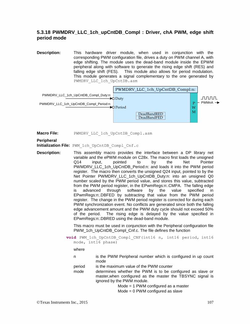
Texas Instruments Inc., 2015 107
5.3.18 PWMDRV_LLC_1ch_upCntDB_Compl : Driver, chA PWM, edge shift period mode
Description: This hardware driver module, when used in conjunction with the corresponding PWM configuration file, drives a duty on PWM channel A, with edge shifting. The module uses the dead-band module inside the EPWM peripheral along with software to generate the rising edge shift (RES) and falling edge shift (FES). This module also allows for period modulation. This module generates a signal complementary to the one generated by PWMDRV_LLC_1ch_UpCntDB.asm
PWMDRV_LLC_1ch_UpCntDB_Compl_Duty:n:
PWM
PWMnA
PWMDRV_LLC_1ch_UpCntDB_Compl:n:
Duty
DeadBandREDDeadBandFED
PWMDRV_LLC_1ch_UpCntDB_Compl_Period:n:Period
Macro File: PWMDRV_LLC_1ch_UpCntDB_Compl.asm
Peripheral
Initialization File: PWM_1ch_UpCntDB_Compl_Cnf.c
Description: This assembly macro provides the interface between a DP library net variable and the ePWM module on C28x. The macro first loads the unsigned Q14 input, pointed to by the Net Pointer PWMDRV_LLC_1ch_UpCntDB_Period:n: and loads it into the PWM period register. The macro then converts the unsigned Q24 input, pointed to by the Net Pointer PWMDRV_LLC_1ch_UpCntDB_Duty:n: into an unsigned Q0 number scaled by the PWM period value, and stores this value, subtracted from the PWM period register, in the EPwmRegs:n:.CMPA. The falling edge is advanced through software by the value specified in EPwmRegs:n:.DBFED by subtracting that value from the PWM period register. The change in the PWM period register is corrected for during each PWM synchronization event. No conflicts are generated since both the falling edge advancement amount and the PWM duty cycle should not exceed 50% of the period. The rising edge is delayed by the value specified in EPwmRegs:n:.DBRED using the dead-band module.
This macro must be used in conjunction with the Peripheral configuration file PWM_1ch_UpCntDB_Compl_Cnf.c. The file defines the function
void PWM_1ch_UpCntDB_Compl_CNF(int16 n, int16 period, int16 mode, int16 phase)
where
n is the PWM Peripheral number which is configured in up count mode
period is the maximum value of the PWM counter
mode determines whether the PWM is to be configured as slave or master,when configured as the master the TBSYNC signal is ignored by the PWM module.
Mode = 1 PWM configured as a master
Mode = 0 PWM configured as slave

Texas Instruments Inc., 2015 108
phase specifies the phase offset that is used when the PWM module is synced. This value only has meaning when the PWM is configured as a slave.
The function configures the PWM peripheral in up-count mode and the dead-band submodule to output PWM chA with dead-band applied. The module outputs an active high duty on ChA of the PWM peripheral. This configuration provides a duty complementary to that configured in PWM_1ch_UpCntDB_Cnf.c
The configuration function only configures the dead-band at initialization time. However, it may be needed to change the dead-band during operation. This can be done by calling the function
void PWM_1ch_UpCntDB_Compl_UpdateDB (int16 n, int16 DbRed,
int16 DbFed)
where
n is the PWM Peripheral number
DbRed is the new rising edge delay
DbFed is the new falling edge delay
Alternatively, an assembly macro is provided to update the dead-band if the update needs to be done at a faster rate, inside the ISR. The dead-band
update assembly macro, PWMDRV_LLC_1ch_UpCntDB_Compl_UpdateDB,
updates the dead-band registers with values stored in the macro variables
PWMDRV_LLC_1ch_UpCntDB_Compl_DeadBandRED:n: and PWMDRV_
LLC_1ch_UpCntDB_Compl_DeadBandFED:n:
. Detailed
Description The following section explains how this module can be used to excite one of the Synchronous Rectifier legs of an LLC Resonant power stage. (Please note this module is specific to using NPN transistors only). The function configures the PWM peripheral in up-count mode. In order to configure a 100Khz switching frequency for the PWM in up-count mode when CPU is operating at 60Mhz, the Period value needed is (System Clock/Switching Frequency) = 600 needs to be provided to the CNF function. The TBPRD is stored with a value of 600-1, to take the up-count mode into account by the CNF function itself.
Duty:n:
PWM
PWMnA
PWMDRV_LLC_1ch_UpCntDB_Compl:n:
Duty
DeadBandREDDeadBandFED
Period:n:Period
LLC ResonantVin Vout
PWM3A
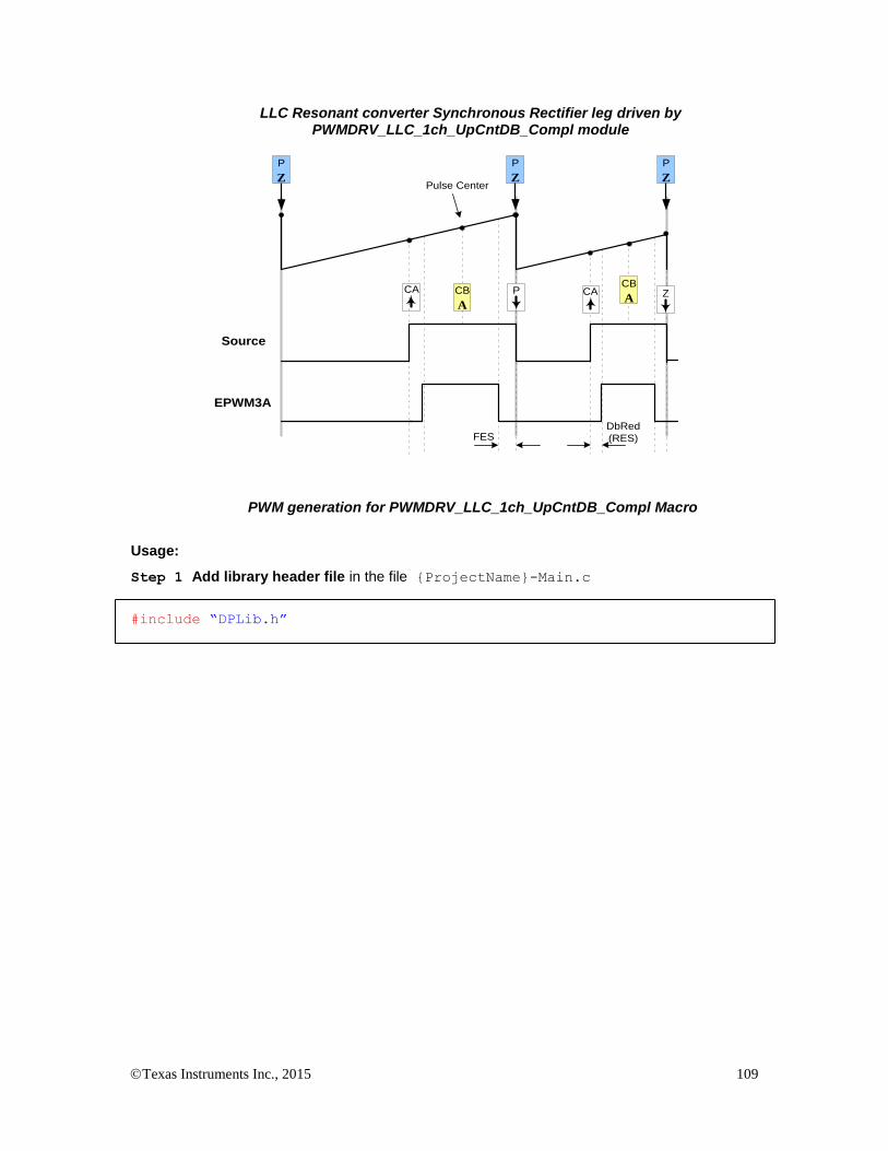
Texas Instruments Inc., 2015 109
LLC Resonant converter Synchronous Rectifier leg driven by PWMDRV_LLC_1ch_UpCntDB_Compl module
Source
CB
A
Pulse Center
PCA CA ZCB
A
P
Z
P
Z
P
Z
EPWM3A
DbRed
(RES)FES
PWM generation for PWMDRV_LLC_1ch_UpCntDB_Compl Macro
Usage:
Step 1 Add library header file in the file {ProjectName}-Main.c
#include “DPLib.h”
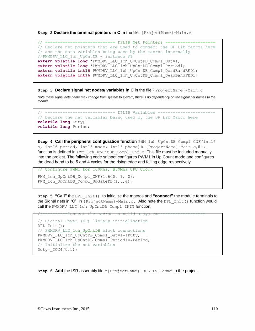
Texas Instruments Inc., 2015 110
Step 2 Declare the terminal pointers in C in the file {ProjectName}-Main.c
// ---------------------------- DPLIB Net Pointers --------------------
// Declare net pointers that are used to connect the DP Lib Macros here
// and the data variables being used by the macros internally
//PWMDRV_LLC_1ch_UpCntDB - instance #1
extern volatile long *PWMDRV_LLC_1ch_UpCntDB_Compl_Duty1;
extern volatile long *PWMDRV_LLC_1ch_UpCntDB_Compl_Period1;
extern volatile int16 PWMDRV_LLC_1ch_UpCntDB_Compl_DeadBandRED1;
extern volatile int16 PWMDRV_LLC_1ch_UpCntDB_Compl_DeadBandFED1;
Step 3 Declare signal net nodes/ variables in C in the file {ProjectName}-Main.c
Note these signal nets name may change from system to system, there is no dependency on the signal net names to the module.
// ---------------------------- DPLIB Variables -----------------------
// Declare the net variables being used by the DP Lib Macro here
volatile long Duty;
volatile long Period;
Step 4 Call the peripheral configuration function PWM_1ch_UpCntDB_Compl_CNF(int16
n, int16 period, int16 mode, int16 phase) in {ProjectName}-Main.c, this
function is defined in PWM_1ch_UpCntDB_Compl_Cnf.c. This file must be included manually
into the project. The following code snippet configures PWM1 in Up Count mode and configures
the dead band to be 5 and 4 cycles for the rising edge and falling edge respectively.
// Configure PWM1 for 100Khz, @60Mhz CPU Clock
PWM_1ch_UpCntDB_Compl_CNF(1,600, 1, 0);
PWM_1ch_UpCntDB_Compl_UpdateDB(1,5,4);
Step 5 “Call” the DPL_Init() to initialize the macros and “connect” the module terminals to
the Signal nets in “C” in {ProjectName}-Main.c. Also note the DPL_Init() function would
call the PWMDRV_LLC_1ch_UpCntDB_Compl_INIT function.
//----------Connect the macros to build a system-------------------
// Digital Power (DP) library initialisation
DPL_Init();
// PWMDRV_LLC_1ch_UpCntDB block connections
PWMDRV_LLC_1ch_UpCntDB_Compl_Duty1=&Duty;
PWMDRV_LLC_1ch_UpCntDB_Compl_Period1=&Period;
// Initialize the net variables
Duty=_IQ24(0.5);
Step 6 Add the ISR assembly file “{ProjectName}-DPL-ISR.asm” to the project.

Texas Instruments Inc., 2015 111
Step 7 Include the macro’s assembly file in the {ProjectName}-DPL-ISR.asm
;Include files for the Power Library Macro's being used by the system
.include "PWMDRV_LLC_1ch_UpCntDB_Compl.asm"
Step 8 Instantiate the INIT macro in assembly (this is one-time pass through code) inside the
C-callable DPL_Init() function which is defined in{ProjectName}-DPL-ISR.asm
;Macro Specific Initialization Functions
PWMDRV_LLC_1ch_UpCntDB_Compl_INIT 1
Step 9 Call the run time macro in assembly inside the C-callable function DPL_ISR() which
is the looped or ISR code. The function is defined in{ProjectName}-DPL-ISR.asm
;”Call” the Run macro
PWMDRV_LLC_1ch_UpCntDB_Compl 1
Step 10 Include the memory sections in the {DeviceName}-{RAM/FLASH}-
{ProjectName}.CMD. Note that the net pointers and the internal data are forced to be placed
in a single data page by use of the .usect directive in the source file of the module.
/*PWMDRV_LLC_1ch_UpCntDB sections*/
PWMDRV_LLC_1ch_UpCntDB_Compl_Section : > dataRAM PAGE = 1
Step 11 Update Dead-Band This can be done by calling the C function in the {ProjectName}-Main.c file.
/*Update dead-band delays */
PWM_1ch_UpCntDB_Compl_UpdateDB(1,7,4);
If the dead band itself is part of the control loop the following assembly maco can be called.
;Update dead-band delays
PWMDRV_LLC_1ch_UpCntDB_Compl_UpdateDB 1
Module Net Definition:
Net name (:n: is the instance number)
Description Format
Acceptable Range of Variable or of the Variable being pointed to
PWMDRV_LLC_1ch_UpCntDB_Compl_Duty:n:
Input Pointer
Pointer to 32 bit fixed point input data location storing Duty Value
Q24: [0, 1)

Texas Instruments Inc., 2015 112
PWMDRV_LLC_1ch_UpCntDB_Compl_Period:n: Input Pointer
Pointer to 32 bit fixed point input data location storing Period Value
Q14: [0, 1024)
PWMDRV_LLC_1ch_UpCntDB_Compl_DeadBandRED:n: Input Variable
Value used by the assembly macro to update the PWM peripheral dead-band registers.
Q0
PWMDRV_LLC_1ch_UpCntDB_Compl_DeadBandFED:n: Input Variable
Value used by the assembly macro to update the PWM peripheral dead-band registers.
Q0
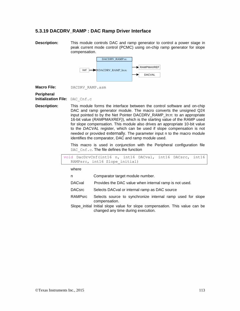
Texas Instruments Inc., 2015 113
5.3.19 DACDRV_RAMP : DAC Ramp Driver Interface
Description: This module controls DAC and ramp generator to control a power stage in peak current mode control (PCMC) using on-chip ramp generator for slope compensation.
Iref
DACDRV_RAMP:n:
DACDRV_RAMP_In:n:RAMPMAXREF
DACVAL
Macro File: DACDRV_RAMP.asm
Peripheral
Initialization File: DAC_Cnf.c
Description: This module forms the interface between the control software and on-chip DAC and ramp generator module. The macro converts the unsigned Q24 input pointed to by the Net Pointer DACDRV_RAMP_In:n: to an appropriate 16-bit value (RAMPMAXREF)), which is the starting value of the RAMP used for slope compensation. This module also drives an appropriate 10-bit value to the DACVAL register, which can be used if slope compensation is not
needed or provided externally. The parameter input n to the macro module
identifies the comparator, DAC and ramp module used.
This macro is used in conjunction with the Peripheral configuration file
DAC_Cnf.c. The file defines the function
void DacDrvCnf(int16 n, int16 DACval, int16 DACsrc, int16
RAMPsrc, int16 Slope_initial)
where
n Comparator target module number.
DACval Provides the DAC value when internal ramp is not used.
DACsrc Selects DACval or internal ramp as DAC source
RAMPsrc Selects source to synchronize internal ramp used for slope compensation.
Slope_initial Initial slope value for slope compensation. This value can be changed any time during execution.

Texas Instruments Inc., 2015 114
Detailed
Description As seen below the PWM sync signal can start the ramp at a known point in the switching cycle. Here this happens at TBCTR = 0. When feedback current equals reference current generated by the DAC and RAMP module it resets the comparator output, which then causes a reset of the ramp to its starting value. Slope of this ramp can be programmed using RAMPDECVAL register. When internal ramp generator is not used (by selecting DACsrc as DACval for DacDrvCnf function), DAC output is a constant reference value set by the DACVAL register value.
DAC Output
PWMx Sync Source
(selected by RAMPsrc)
Comparator
output change
Start of ramp
TBCTR = 0
RAMPMAXREF
DACVAL
Current Feedback
RAMPDECVAL
defines ramp slope
DAC and ramp for PCMC control of a power stage
Usage:
Step 1 Add library header file in the file {ProjectName}-Main.c
#include “DPLib.h”
Step 2 Declare the terminal pointers in C in the file {ProjectName}-Main.c
// ---------------------------- DPLIB Net Pointers --------------------
// Declare net pointers that are used to connect the DP Lib Macros here
// and the data variables being used by the macros internally
// DACDRV_RAMP
extern volatile long *DACDRV_RAMP_In1;
Step 3 Declare signal net nodes/ variables in C in the file {ProjectName}-Main.c
Note these signal nets name may change from system to system, there is no dependency on the signal net names to the module.
// ---------------------------- DPLIB Variables -----------------------
// Declare the net variables being used by the DP Lib Macro here
volatile long Iref = 0;
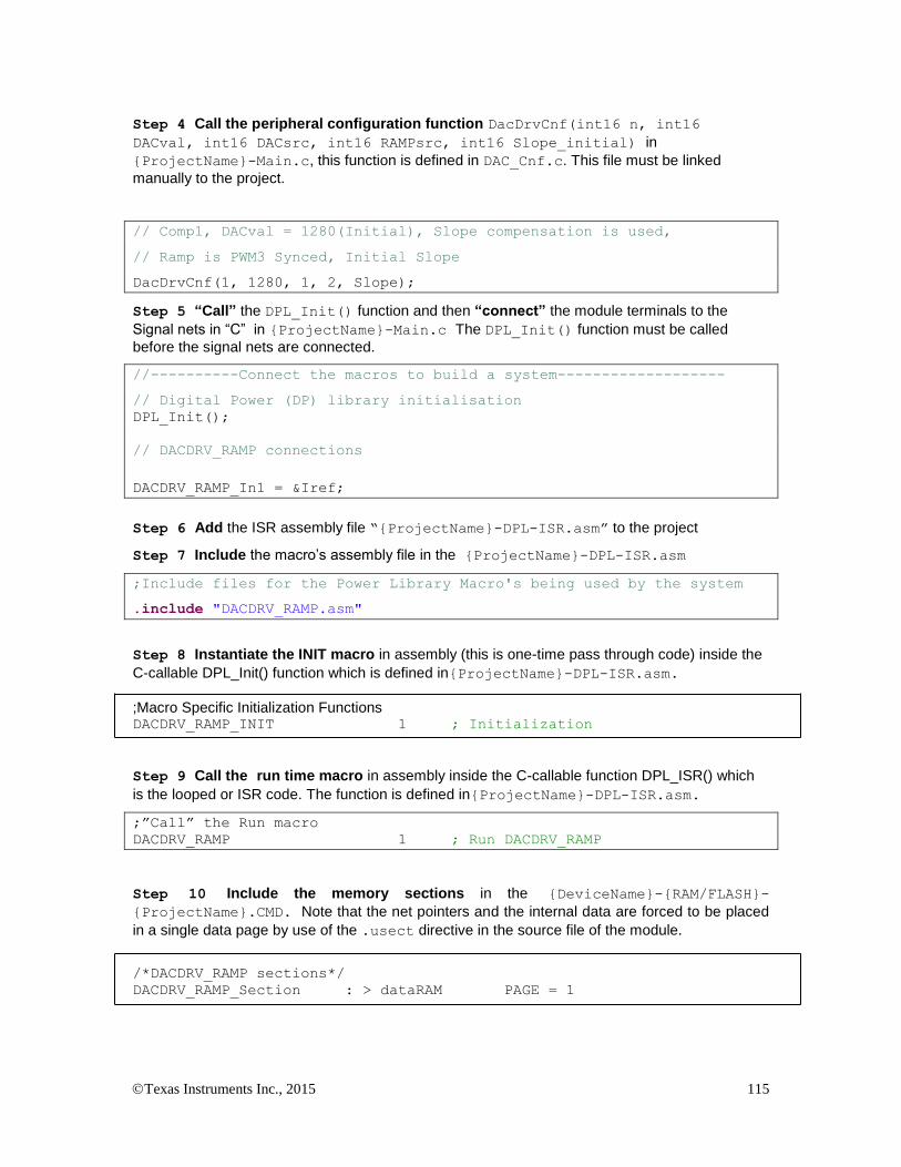
Texas Instruments Inc., 2015 115
Step 4 Call the peripheral configuration function DacDrvCnf(int16 n, int16
DACval, int16 DACsrc, int16 RAMPsrc, int16 Slope_initial) in
{ProjectName}-Main.c, this function is defined in DAC_Cnf.c. This file must be linked
manually to the project.
// Comp1, DACval = 1280(Initial), Slope compensation is used,
// Ramp is PWM3 Synced, Initial Slope
DacDrvCnf(1, 1280, 1, 2, Slope);
Step 5 “Call” the DPL_Init() function and then “connect” the module terminals to the
Signal nets in “C” in {ProjectName}-Main.c The DPL_Init() function must be called
before the signal nets are connected.
//----------Connect the macros to build a system-------------------
// Digital Power (DP) library initialisation
DPL_Init();
// DACDRV_RAMP connections
DACDRV_RAMP_In1 = &Iref;
Step 6 Add the ISR assembly file “{ProjectName}-DPL-ISR.asm” to the project
Step 7 Include the macro’s assembly file in the {ProjectName}-DPL-ISR.asm
;Include files for the Power Library Macro's being used by the system
.include "DACDRV_RAMP.asm"
Step 8 Instantiate the INIT macro in assembly (this is one-time pass through code) inside the
C-callable DPL_Init() function which is defined in{ProjectName}-DPL-ISR.asm.
;Macro Specific Initialization Functions DACDRV_RAMP_INIT 1 ; Initialization
Step 9 Call the run time macro in assembly inside the C-callable function DPL_ISR() which
is the looped or ISR code. The function is defined in{ProjectName}-DPL-ISR.asm.
;”Call” the Run macro
DACDRV_RAMP 1 ; Run DACDRV_RAMP
Step 10 Include the memory sections in the {DeviceName}-{RAM/FLASH}-
{ProjectName}.CMD. Note that the net pointers and the internal data are forced to be placed
in a single data page by use of the .usect directive in the source file of the module.
/*DACDRV_RAMP sections*/
DACDRV_RAMP_Section : > dataRAM PAGE = 1

Texas Instruments Inc., 2015 116
Module Net Definition:
Net name (:n: is the instance number)
Description Format Acceptable Range of Variable or of the Variable being pointed to
DACDRV_RAMP_In:n:
Input Pointer Pointer to 32 bit fixed point input data location to current reference value
Q24(0,1)
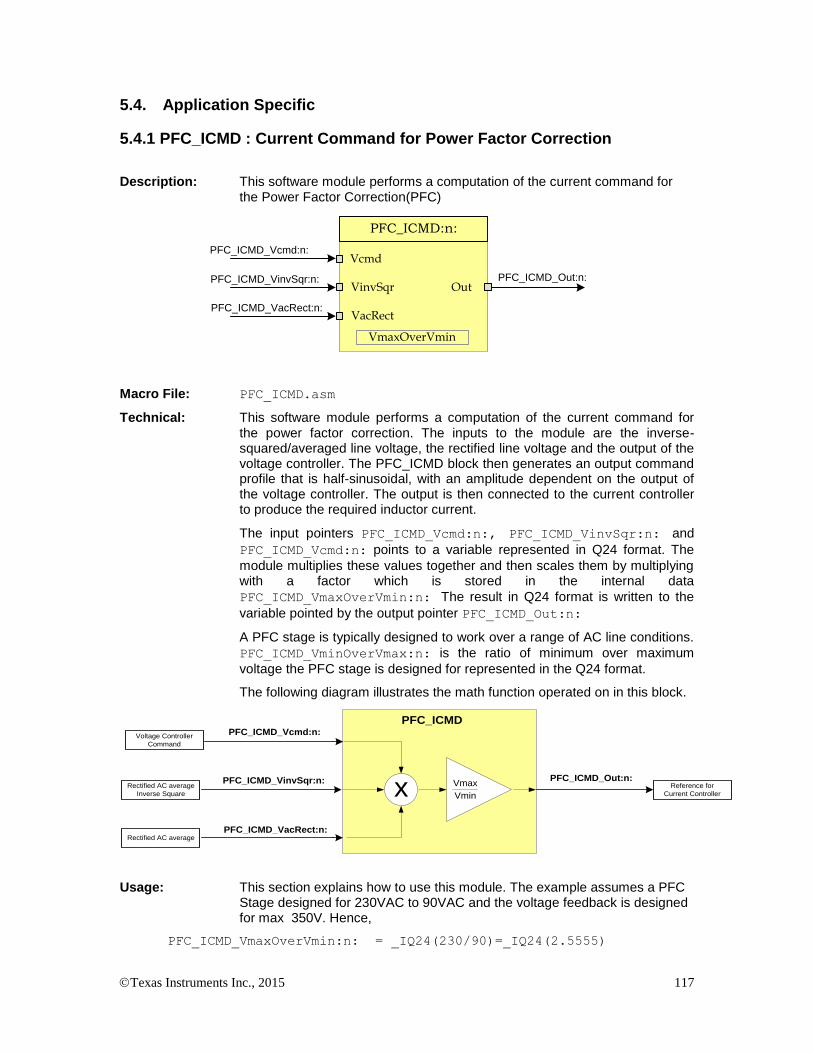
Texas Instruments Inc., 2015 117
5.4. Application Specific
5.4.1 PFC_ICMD : Current Command for Power Factor Correction
Description: This software module performs a computation of the current command for the Power Factor Correction(PFC)
PFC_ICMD_Vcmd:n:
PFC_ICMD_Out:n:
PFC_ICMD_VacRect:n:
PFC_ICMD_VinvSqr:n:
PFC_ICMD:n:
Vcmd
Out
VmaxOverVmin
VinvSqr
VacRect
Macro File: PFC_ICMD.asm
Technical: This software module performs a computation of the current command for the power factor correction. The inputs to the module are the inverse-squared/averaged line voltage, the rectified line voltage and the output of the voltage controller. The PFC_ICMD block then generates an output command profile that is half-sinusoidal, with an amplitude dependent on the output of the voltage controller. The output is then connected to the current controller to produce the required inductor current.
The input pointers PFC_ICMD_Vcmd:n:, PFC_ICMD_VinvSqr:n: and
PFC_ICMD_Vcmd:n: points to a variable represented in Q24 format. The
module multiplies these values together and then scales them by multiplying with a factor which is stored in the internal data
PFC_ICMD_VmaxOverVmin:n: The result in Q24 format is written to the
variable pointed by the output pointer PFC_ICMD_Out:n:
A PFC stage is typically designed to work over a range of AC line conditions.
PFC_ICMD_VminOverVmax:n: is the ratio of minimum over maximum
voltage the PFC stage is designed for represented in the Q24 format.
The following diagram illustrates the math function operated on in this block.
PFC_ICMD_VinvSqr:n:
PFC_ICMD
PFC_ICMD_Out:n:
x Vmax
Vmin
PFC_ICMD_Vcmd:n:
PFC_ICMD_VacRect:n:
Voltage Controller
Command
Rectified AC average
Inverse Square
Rectified AC average
Reference for
Current Controller
Usage: This section explains how to use this module. The example assumes a PFC Stage designed for 230VAC to 90VAC and the voltage feedback is designed for max 350V. Hence,
PFC_ICMD_VmaxOverVmin:n: = _IQ24(230/90)=_IQ24(2.5555)
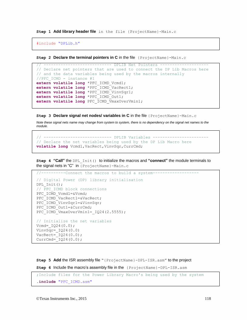
Texas Instruments Inc., 2015 118
Step 1 Add library header file in the file {ProjectName}-Main.c
#include “DPLib.h”
Step 2 Declare the terminal pointers in C in the file {ProjectName}-Main.c
// ---------------------------- DPLIB Net Pointers --------------------
// Declare net pointers that are used to connect the DP Lib Macros here
// and the data variables being used by the macros internally
//PFC_ICMD - instance #1
extern volatile long *PFC_ICMD_Vcmd1;
extern volatile long *PFC_ICMD_VacRect1;
extern volatile long *PFC_ICMD_VinvSqr1;
extern volatile long *PFC_ICMD_Out1;
extern volatile long PFC_ICMD_VmaxOverVmin1;
Step 3 Declare signal net nodes/ variables in C in the file {ProjectName}-Main.c
Note these signal nets name may change from system to system, there is no dependency on the signal net names to the module.
// ---------------------------- DPLIB Variables -----------------------
// Declare the net variables being used by the DP Lib Macro here
volatile long Vcmd1,VacRect,VinvSqr,CurrCmd;
Step 4 “Call” the DPL_Init() to initialize the macros and “connect” the module terminals to
the signal nets in “C” in {ProjectName}-Main.c
//----------Connect the macros to build a system-------------------
// Digital Power (DP) library initialisation
DPL_Init();
// PFC_ICMD block connections
PFC_ICMD_Vcmd1=&Vcmd;
PFC_ICMD_VacRect1=&VacRect;
PFC_ICMD_VinvSqr1=&VinvSqr;
PFC_ICMD_Out1=&CurrCmd;
PFC_ICMD_VmaxOverVmin1=_IQ24(2.5555);
// Initialize the net variables
Vcmd=_IQ24(0.0);
VinvSqr=_IQ24(0.0)
VacRect=_IQ24(0.0);
CurrCmd=_IQ24(0.0);
Step 5 Add the ISR assembly file “{ProjectName}-DPL-ISR.asm” to the project
Step 6 Include the macro’s assembly file in the {ProjectName}-DPL-ISR.asm
;Include files for the Power Library Macro's being used by the system
.include "PFC_ICMD.asm"

Texas Instruments Inc., 2015 119
Step 7 Instantiate the INIT macro in assembly (this is one-time pass through code) inside the
C-callable DPL_Init() function which is defined in{ProjectName}-DPL-ISR.asm
;Macro Specific Initialization Functions
PFC_ICMD_INIT 1 ; PFC_ICMD Initialization
Step 8 Call the run time macro in assembly inside the C-callable function DPL_ISR() which
is the looped or ISR code. The function is defined in{ProjectName}-DPL-ISR.asm
;”Call” the Run macro
PFC_ICMD 1 ; Run the PFC_ICMD Macro
Step 9 Include the memory sections in the {DeviceName}-{RAM/FLASH}-
{ProjectName}.CMD. Note that the net pointers and the internal data are forced to be placed
in a single data page by use of the .usect directive in the source file of the module.
/*PFC_ICMD sections*/
PFC_ICMD_Section : > RAML2 PAGE = 1
Module Net Definition:
Net name (:n: is the instance number)
Description Format Acceptable Range
PFC_ICMD_Vcmd:n:
Input Pointer
Pointer to 32 bit fixed point input data location storing the output of the voltage controller
Q24: [0, 1)
PFC_ICMD_VinvSqr:n:
Input Pointer
Pointer to 32 bit fixed point input data location storing the output of the PFC_INVSQR block
Q24: [0, 1)
PFC_ICMD_VacRect:n: Input Pointer
Pointer to 32 bit fixed point input data location storing the output of the MATH_EMAVG block
Q24:[0,1)
PFC_ICMD_Out:n: Output Pointer
Pointer to 32 bit fixed point output location where the reference for the current loop is stored
Q24:[ 0,1)
PFC_ICMD_VmaxOverVmin:n: Internal Data
Data Variable storing the scaling factor
Q24:[0,8)

Texas Instruments Inc., 2015 120
5.4.2 PFC_INVSQR : Inverse Square Math Block for Power Factor Correction
Description: This software module performs a reciprocal function on a scaled unipolar input signal and squares it.
PFC_INVSQR_In:n: PFC_INVSQR_Out:n:
PFC_INVSQR:n:
In Out
VminOverVmaxVmin
Macro File: PFC_INVSQR.asm
Technical: The input pointer PFC_INSQR_In:n: points to a variable represented in
Q24 format. The module scales and inverts this value and writes the result in
Q24 format to a variable pointed by the output pointer PFC_INVSQR_Out:n:
The module uses two internal data variables to specify the range and scaling, which is dependent on the Power Factor Correction(PFC) stage the module is used for.
A PFC stage is typically designed to work over a range of AC line conditions.
PFC_INVSQR_VminOverVmax:n: is the ratio of minimum over maximum
voltage the PFC stage is designed for represented in the Q30 format. The
PFC_INVSQR_Vmin:n: is equal or less than the minimum AC Line voltage
that the PFC stage is designed to run for represented in the Q24 format.
Note that PFC_INVSQR_Vmin:n: depends on what range the Voltage
Feedback in the PFC system is designed for.
The module allows for the fact that the input value is the average of a half-sine (rectified AC), whereas what is desired for power factor correction is the representation of the peak of the sine. In addition the input signal is clamped to a minimum to allow the PFC system to work with very low line voltages without overflows, which can cause undesirable effects. The module also saturates the output for a maximum of 1.0 in Q24 format. The following diagram illustrates the math function operated on in this block.
PFC_INVSQR_In:n:
In
PFC_INVSQR
PFC_INVSQR_Out:n:PI
2
1
x
Vmin
Vmaxx
2Rect. AC Avg
Value Variable
Inverse Square
Value Variable
Usage: This section explains how to use this module. The example assumes a PFC Stage designed for 230VAC to 90VAC and the voltage feedback is designed for peak 400V. Hence,
PFC_INVSQR_VminOverVmax:n: = _IQ30(90/230)=_IQ30(0.3913)
PFC_INVSQR_Vmin:n: =<_IQ24(90/400)=_IQ24(0.225)
Step 1 Add library header file in the file {ProjectName}-Main.c
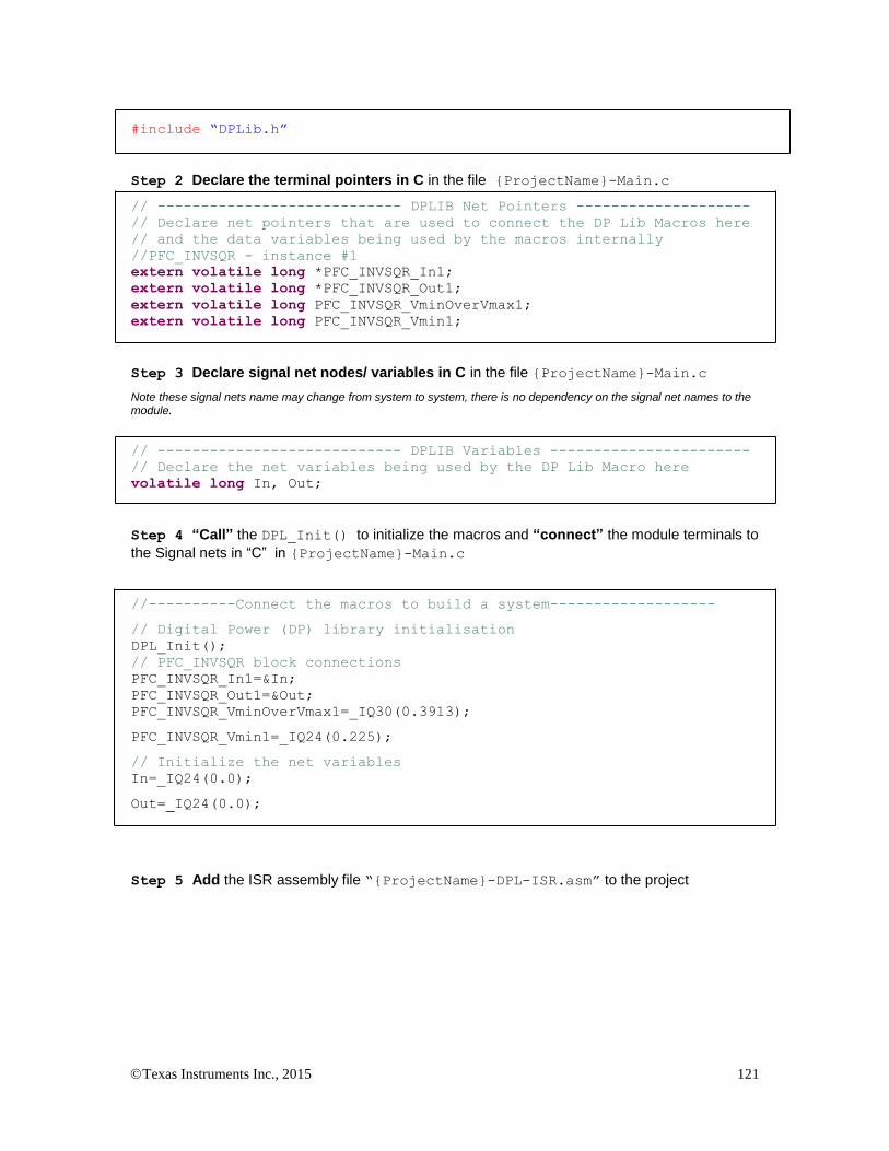
Texas Instruments Inc., 2015 121
#include “DPLib.h”
Step 2 Declare the terminal pointers in C in the file {ProjectName}-Main.c
// ---------------------------- DPLIB Net Pointers --------------------
// Declare net pointers that are used to connect the DP Lib Macros here
// and the data variables being used by the macros internally
//PFC_INVSQR - instance #1
extern volatile long *PFC_INVSQR_In1;
extern volatile long *PFC_INVSQR_Out1;
extern volatile long PFC_INVSQR_VminOverVmax1;
extern volatile long PFC_INVSQR_Vmin1;
Step 3 Declare signal net nodes/ variables in C in the file {ProjectName}-Main.c
Note these signal nets name may change from system to system, there is no dependency on the signal net names to the module.
// ---------------------------- DPLIB Variables -----------------------
// Declare the net variables being used by the DP Lib Macro here
volatile long In, Out;
Step 4 “Call” the DPL_Init() to initialize the macros and “connect” the module terminals to
the Signal nets in “C” in {ProjectName}-Main.c
//----------Connect the macros to build a system-------------------
// Digital Power (DP) library initialisation
DPL_Init();
// PFC_INVSQR block connections
PFC_INVSQR_In1=&In;
PFC_INVSQR_Out1=&Out;
PFC_INVSQR_VminOverVmax1=_IQ30(0.3913);
PFC_INVSQR_Vmin1=_IQ24(0.225);
// Initialize the net variables
In=_IQ24(0.0);
Out=_IQ24(0.0);
Step 5 Add the ISR assembly file “{ProjectName}-DPL-ISR.asm” to the project
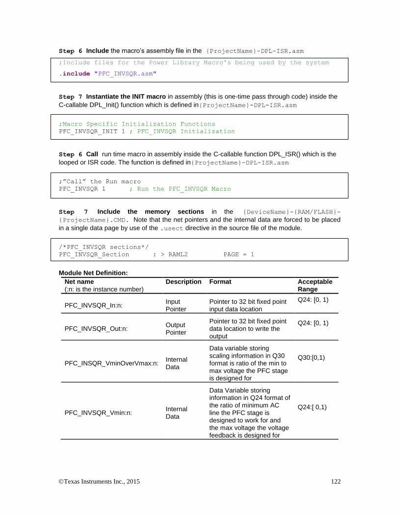
Texas Instruments Inc., 2015 122
Step 6 Include the macro’s assembly file in the {ProjectName}-DPL-ISR.asm
;Include files for the Power Library Macro's being used by the system
.include "PFC_INVSQR.asm"
Step 7 Instantiate the INIT macro in assembly (this is one-time pass through code) inside the
C-callable DPL_Init() function which is defined in{ProjectName}-DPL-ISR.asm
;Macro Specific Initialization Functions
PFC_INVSQR_INIT 1 ; PFC_INVSQR Initialization
Step 6 Call run time macro in assembly inside the C-callable function DPL_ISR() which is the
looped or ISR code. The function is defined in{ProjectName}-DPL-ISR.asm
;”Call” the Run macro
PFC_INVSQR 1 ; Run the PFC_INVSQR Macro
Step 7 Include the memory sections in the {DeviceName}-{RAM/FLASH}-
{ProjectName}.CMD. Note that the net pointers and the internal data are forced to be placed
in a single data page by use of the .usect directive in the source file of the module.
/*PFC_INVSQR sections*/
PFC_INVSQR_Section : > RAML2 PAGE = 1
Module Net Definition:
Net name (:n: is the instance number)
Description Format Acceptable Range
PFC_INVSQR_In:n: Input Pointer
Pointer to 32 bit fixed point input data location
Q24: [0, 1)
PFC_INVSQR_Out:n: Output Pointer
Pointer to 32 bit fixed point data location to write the output
Q24: [0, 1)
PFC_INSQR_VminOverVmax:n: Internal Data
Data variable storing scaling information in Q30 format is ratio of the min to max voltage the PFC stage is designed for
Q30:[0,1)
PFC_INVSQR_Vmin:n: Internal Data
Data Variable storing information in Q24 format of the ratio of minimum AC line the PFC stage is designed to work for and the max voltage the voltage feedback is designed for
Q24:[ 0,1)

Texas Instruments Inc., 2015 123
5.4.3 PFC_BL_ICMD : Bridgeless PFC Current Command
Description: This software module performs a computation of the current command for the Power Factor Correction (PFC) stage that uses PFC boost switch current sensing in order to control the PFC inductor current.
PFC_BL_ ICMD_ Vcmd:n:
PFC_BL_ ICMD_ VacRect
PFC_BL_ ICMD_ VinvSqr:n:
PFC_BL_ ICMD:n:
Vcmd
OutVinvSqr
VacRect:n:
PFC_BL_ ICMD_ Duty:n:
PFC_BL_ ICMD_Vpfc :n:Duty
Vbus
VmaxOverVmin
Vout_maxOverVin_max
PFC_BL_ ICMD_Out:
Macro File: PFC_BL_ICMD.asm
Technical: This software module performs a computation of the current command for the power factor correction stage that uses boost PFC switch current sensing in order to implement PFC input current control. The inputs to the module are the inverse-squared-rms line voltage, the rectified line voltage, PFC PWM duty ratio, PFC dc bus voltage and the output of the voltage loop controller. The PFC_BL_ICMD block then generates an output command profile which is then connected to the current controller to produce the required inductor current.
Five input pointers PFC_BL_ICMD_Vcmd:n:,
PFC_BL_ICMD_VinvSqr:n:, PFC_BL_ICMD_VacRect:n:,
PFC_BL_ICMD_Duty:n:, and PFC_BL_ICMD_Vpfc:n: point to variables
represented in Q24 format. The module uses these inputs to implement a math function and then scales the result by multiplying with a factor which is
stored in the internal data PFC_BL_ICMD_VmaxOverVmin:n: The final
result in Q24 format is written to the variable pointed to by the output pointer PFC_BL_ICMD_Out:n:
A PFC stage is typically designed to work over a range of input and output
voltages. PFC_BL_ICMD_VminOverVmax:n: is the ratio of minimum over
maximum AC input voltage the PFC stage is designed for represented in
Q24 format. PFC_BL_ICMD_Vout_maxOverVin_max:n: is the ratio of
maximum output voltage over maximum AC input voltage and represented in Q24 format.The following diagram illustrates the math function operated on in this block.

Texas Instruments Inc., 2015 124
PFC_ BL_ICMD
x
Voltage Controller
Command
Rectified AC
Reference for
Current Controller x-
+
Vmax
Vminx
+PFC DC Bus
Voltage
PFC PWM Duty
x 1y
y
(Vpfc_scaled – VacRect)
PFC_BL_ ICMD_Out: n :
PFC_BL_ ICMD_ Vcmd :n:
PFC_BL _ ICMD_ VinvSqr:n:
PFC_BL _ ICMD_ VacRect:n:
:PFC_BL_ICMD_Vpfc:n
n:PFC_BL _ ICMD_ Duty:
Vout_max
Vin_max
Rectified AC RMS
Inverse Square
Vpfc_scaled
Usage: This section explains how to use this module. The example assumes a PFC Stage designed for input AC range of 280Vrms to 80Vrms and the max DC bus voltage of 450V. Hence,
PFC_BL_ICMD_VmaxOverVmin:n: = _IQ24(280/80)=_IQ24(3.5)
PFC_BL_ICMD_Vout_maxOverVin_max:n: =
_IQ24(450/(1.414*280))=_IQ24(1.14)
Step 1 Add library header file in the file {ProjectName}-Main.c
#include “DPLib.h”
Step 2 Declare the terminal pointers in C in the file {ProjectName}-Main.c
// ---------------------------- DPLIB Net Pointers --------------------
-
// Declare net pointers that are used to connect the DP Lib Macros here
// and the data variables being used by the macros internally
//PFC_BL_ICMD - instance #1
extern volatile long *PFC_BL_ICMD_Vcmd1;
extern volatile long *PFC_BL_ICMD_VinvSqr1;
extern volatile long *PFC_BL_ICMD_VacRect1;
extern volatile long *PFC_BL_ICMD_Out1;
extern volatile long PFC_BL_ICMD_VmaxOverVmin1;
extern volatile long *PFC_BL_ICMD_Vpfc1;
extern volatile long *PFC_BL_ICMD_Duty1;
extern volatile long PFC_BL_ICMD_VoutMaxOverVinMax1;
Step 3 Declare signal net nodes/ variables in C in the file {ProjectName}-Main.c
Note these signal nets name may change from system to system, there is no dependency on the signal net names to the module.
// ---------------------------- DPLIB Variables -----------------------
// Declare the net variables being used by the DP Lib Macro here
volatile long Vcmd,VacRect,VinvSqr,CurrCmd, Duty, Vpfc;

Texas Instruments Inc., 2015 125
Step 4 “Call” the DPL_Init() to initialize the macros and “connect” the module terminals to
the signal nets in “C” in {ProjectName}-Main.c
//----------Connect the macros to build a system-------------------
// Digital Power (DP) library initialization
DPL_Init();
// PFC_BL_ICMD block connections
PFC_BL_ICMD_Vcmd1 = &VbusVcmd;
PFC_BL_ICMD_VinvSqr1=&VinvSqr;
PFC_BL_ICMD_VacRect1=&Vrect;
PFC_BL_ICMD_Out1=&PFCIcmd;
PFC_BL_ICMD_VmaxOverVmin1=_IQ24(3.5);
PFC_BL_ICMD_Vpfc1 = &Vbus;
PFC_BL_ICMD_Duty1 = &DutyA;
PFC_BL_ICMD_VoutMaxOverVinMax1 = _IQ24(1.14);
Vcmd=_IQ24(0.0);
VinvSqr=_IQ24(0.0)
VacRect=_IQ24(0.0);
CurrCmd=_IQ24(0.0);
Step 5 Add the ISR assembly file “{ProjectName}-DPL-ISR.asm” to the project
Step 6 Include the macro’s assembly file in the {ProjectName}-DPL-ISR.asm
;Include files for the Power Library Macro's being used by the system
.include "PFC_BL_ICMD.asm"
Step 7 Instantiate the INIT macro in assembly (this is one-time pass through code) inside the
C-callable DPL_Init() function which is defined in{ProjectName}-DPL-ISR.asm
;Macro Specific Initialization Functions
PFC_BL_ICMD_INIT 1 ; PFC_BL_ICMD Initialization
Step 8 Call the run time macro in assembly inside the C-callable function DPL_ISR() which
is the looped or ISR code. The function is defined in{ProjectName}-DPL-ISR.asm
;”Call” the Run macro
PFC_BL_ICMD 1 ; Run the PFC_BL_ICMD Macro
Step 9 Include the memory sections in the {DeviceName}-{RAM/FLASH}-
{ProjectName}.CMD. Note that the net pointers and the internal data are forced to be placed
in a single data page by use of the .usect directive in the source file of the module.
/*PFC_BL_ICMD sections*/
PFC_BL_ICMD_Section : > RAML2 PAGE = 1
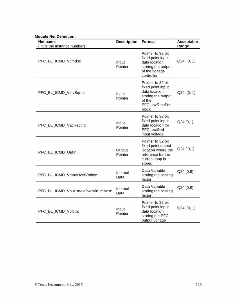
Texas Instruments Inc., 2015 126
Module Net Definition:
Net name (:n: is the instance number)
Description Format Acceptable Range
PFC_BL_ICMD_Vcmd:n:
Input Pointer
Pointer to 32 bit fixed point input data location storing the output of the voltage controller
Q24: [0, 1)
PFC_BL_ICMD_VinvSqr:n:
Input Pointer
Pointer to 32 bit fixed point input data location storing the output of the PFC_InvRmsSqr block
Q24: [0, 1)
PFC_BL_ICMD_VacRect:n: Input Pointer
Pointer to 32 bit fixed point input data location for PFC rectified input voltage
Q24:[0,1)
PFC_BL_ICMD_Out:n: Output Pointer
Pointer to 32 bit fixed point output location where the reference for the current loop is stored
Q24:[ 0,1)
PFC_BL_ICMD_VmaxOverVmin:n: Internal Data
Data Variable storing the scaling factor
Q24:[0,8)
PFC_BL_ICMD_Vout_maxOverVin_max:n: Internal Data
Data Variable storing the scaling factor
Q24:[0,8)
PFC_BL_ICMD_Vpfc:n: Input Pointer
Pointer to 32 bit fixed point input data location storing the PFC output voltage
Q24: [0, 1)
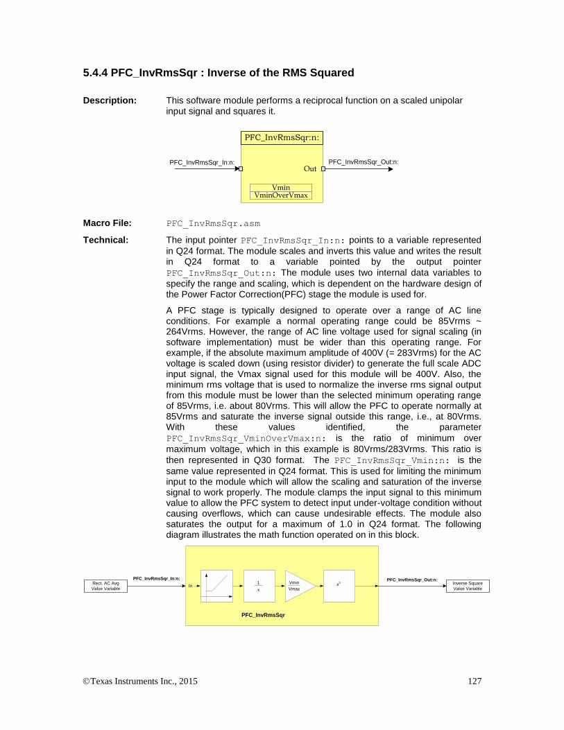
Texas Instruments Inc., 2015 127
5.4.4 PFC_InvRmsSqr : Inverse of the RMS Squared
Description: This software module performs a reciprocal function on a scaled unipolar input signal and squares it.
PFC_InvRmsSqr_In:n: PFC_InvRmsSqr_Out:n:In
PFC_InvRmsSqr:n:
Out
VminOverVmaxVmin
Macro File: PFC_InvRmsSqr.asm
Technical: The input pointer PFC_InvRmsSqr_In:n: points to a variable represented
in Q24 format. The module scales and inverts this value and writes the result in Q24 format to a variable pointed by the output pointer
PFC_InvRmsSqr_Out:n: The module uses two internal data variables to
specify the range and scaling, which is dependent on the hardware design of the Power Factor Correction(PFC) stage the module is used for.
A PFC stage is typically designed to operate over a range of AC line conditions. For example a normal operating range could be 85Vrms ~ 264Vrms. However, the range of AC line voltage used for signal scaling (in software implementation) must be wider than this operating range. For example, if the absolute maximum amplitude of 400V (= 283Vrms) for the AC voltage is scaled down (using resistor divider) to generate the full scale ADC input signal, the Vmax signal used for this module will be 400V. Also, the minimum rms voltage that is used to normalize the inverse rms signal output from this module must be lower than the selected minimum operating range of 85Vrms, i.e. about 80Vrms. This will allow the PFC to operate normally at 85Vrms and saturate the inverse signal outside this range, i.e., at 80Vrms. With these values identified, the parameter
PFC_InvRmsSqr_VminOverVmax:n: is the ratio of minimum over
maximum voltage, which in this example is 80Vrms/283Vrms. This ratio is
then represented in Q30 format. The PFC_InvRmsSqr_Vmin:n: is the
same value represented in Q24 format. This is used for limiting the minimum input to the module which will allow the scaling and saturation of the inverse signal to work properly. The module clamps the input signal to this minimum value to allow the PFC system to detect input under-voltage condition without causing overflows, which can cause undesirable effects. The module also saturates the output for a maximum of 1.0 in Q24 format. The following diagram illustrates the math function operated on in this block.
PFC_InvRmsSqr_In:n:
In
PFC_InvRmsSqr
PFC_InvRmsSqr_Out:n:1
x
Vmin
Vmaxx
2Rect. AC Avg
Value Variable
Inverse Square
Value Variable
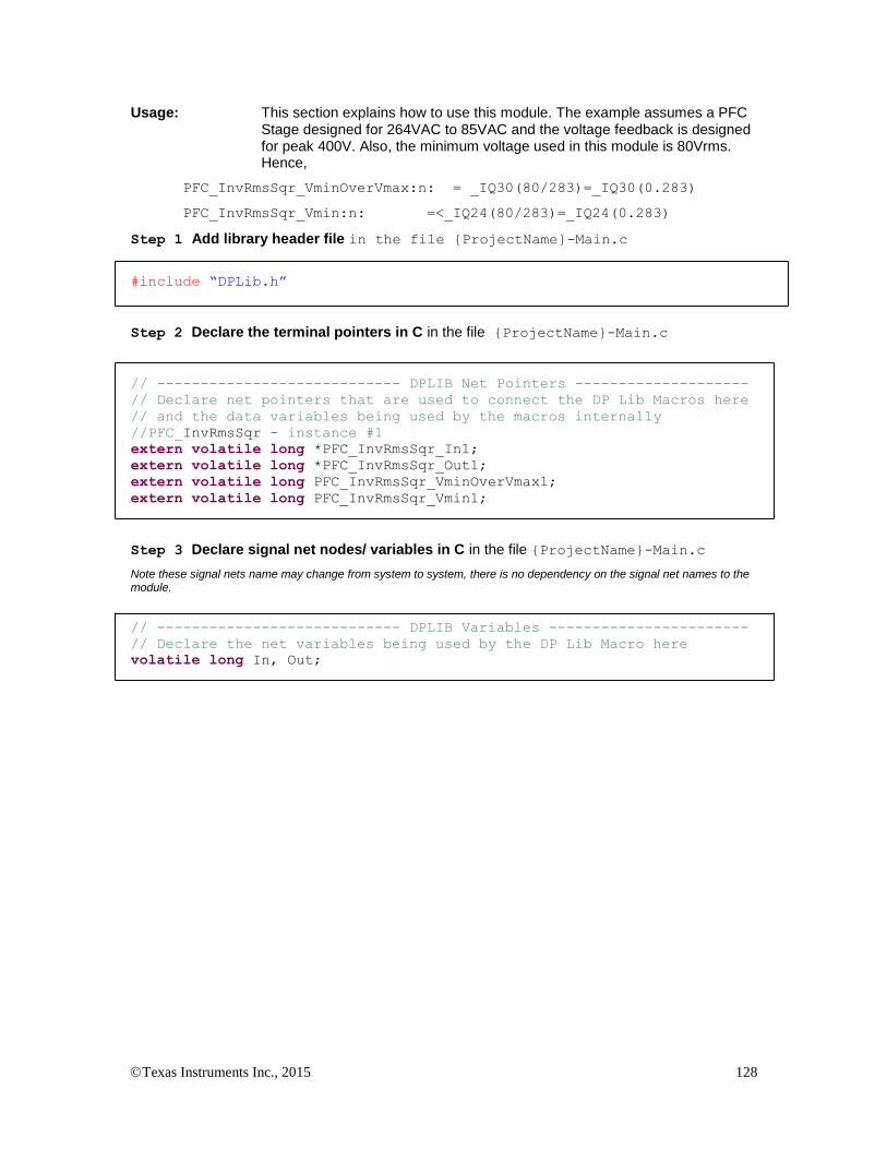
Texas Instruments Inc., 2015 128
Usage: This section explains how to use this module. The example assumes a PFC Stage designed for 264VAC to 85VAC and the voltage feedback is designed for peak 400V. Also, the minimum voltage used in this module is 80Vrms. Hence,
PFC_InvRmsSqr_VminOverVmax:n: = _IQ30(80/283)=_IQ30(0.283)
PFC_InvRmsSqr_Vmin:n: =<_IQ24(80/283)=_IQ24(0.283)
Step 1 Add library header file in the file {ProjectName}-Main.c
#include “DPLib.h”
Step 2 Declare the terminal pointers in C in the file {ProjectName}-Main.c
// ---------------------------- DPLIB Net Pointers --------------------
// Declare net pointers that are used to connect the DP Lib Macros here
// and the data variables being used by the macros internally
//PFC_InvRmsSqr - instance #1
extern volatile long *PFC_InvRmsSqr_In1;
extern volatile long *PFC_InvRmsSqr_Out1;
extern volatile long PFC_InvRmsSqr_VminOverVmax1;
extern volatile long PFC_InvRmsSqr_Vmin1;
Step 3 Declare signal net nodes/ variables in C in the file {ProjectName}-Main.c
Note these signal nets name may change from system to system, there is no dependency on the signal net names to the module.
// ---------------------------- DPLIB Variables -----------------------
// Declare the net variables being used by the DP Lib Macro here
volatile long In, Out;

Texas Instruments Inc., 2015 129
Step 4 “Call” the DPL_Init() to initialize the macros and “connect” the module terminals to
the Signal nets in “C” in {ProjectName}-Main.c
//----------Connect the macros to build a system-------------------
// Digital Power (DP) library initialisation
DPL_Init();
// PFC_INVSQR block connections
PFC_InvRmsSqr_In1=&In;
PFC_InvRmsSqr_Out1=&Out;
PFC_InvRmsSqr_VminOverVmax1=_IQ30(0.3913);
PFC_InvRmsSqr_Vmin1=_IQ24(0.225);
// Initialize the net variables
In=_IQ24(0.0);
Out=_IQ24(0.0);
Step 5 Add the ISR assembly file “{ProjectName}-DPL-ISR.asm” to the project
Step 6 Include the macro’s assembly file in the {ProjectName}-DPL-ISR.asm
;Include files for the Power Library Macro's being used by the system
.include "PFC_InvRmsSqr.asm"
Step 7 Instantiate the INIT macro in assembly (this is one-time pass through code) inside the
C-callable DPL_Init() function which is defined in{ProjectName}-DPL-ISR.asm
;Macro Specific Initialization Functions
PFC_InvRmsSqr_INIT 1 ; PFC_INVSQR Initialization
Step 8 Call run time macro in assembly inside the C-callable function DPL_ISR() which is the
looped or ISR code. The function is defined in{ProjectName}-DPL-ISR.asm
;”Call” the Run macro
PFC_InvRmsSqr 1 ; Run the PFC_INVSQR Macro
Step 9 Include the memory sections in the {DeviceName}-{RAM/FLASH}-
{ProjectName}.CMD. Note that the net pointers and the internal data are forced to be placed
in a single data page by use of the .usect directive in the source file of the module.
/*PFC_InvRmsSqr sections*/
PFC_InvRmsSqr_Section : > RAML2 PAGE = 1
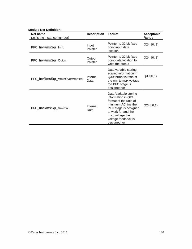
Texas Instruments Inc., 2015 130
Module Net Definition:
Net name (:n: is the instance number)
Description Format Acceptable Range
PFC_InvRmsSqr_In:n: Input Pointer
Pointer to 32 bit fixed point input data location
Q24: [0, 1)
PFC_InvRmsSqr_Out:n: Output Pointer
Pointer to 32 bit fixed point data location to write the output
Q24: [0, 1)
PFC_InvRmsSqr_VminOverVmax:n: Internal Data
Data variable storing scaling information in Q30 format is ratio of the min to max voltage the PFC stage is designed for
Q30:[0,1)
PFC_InvRmsSqr_Vmin:n: Internal Data
Data Variable storing information in Q24 format of the ratio of minimum AC line the PFC stage is designed to work for and the max voltage the voltage feedback is designed for
Q24:[ 0,1)
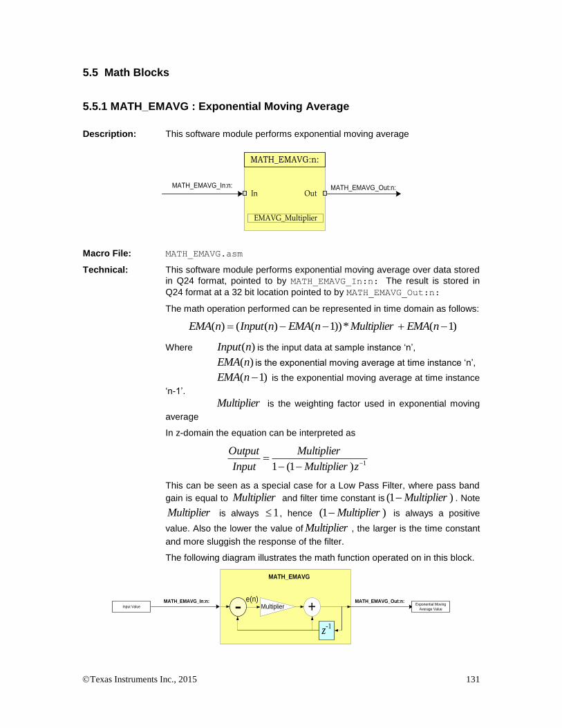
Texas Instruments Inc., 2015 131
5.5 Math Blocks
5.5.1 MATH_EMAVG : Exponential Moving Average
Description: This software module performs exponential moving average
MATH_EMAVG_Out:n:MATH_EMAVG_In:n:
MATH_EMAVG:n:
In Out
EMAVG_Multiplier
Macro File: MATH_EMAVG.asm
Technical: This software module performs exponential moving average over data stored
in Q24 format, pointed to by MATH_EMAVG_In:n: The result is stored in
Q24 format at a 32 bit location pointed to by MATH_EMAVG_Out:n:
The math operation performed can be represented in time domain as follows:
)1(*))1()(()( nEMAMultipliernEMAnInputnEMA
Where )(nInput is the input data at sample instance ‘n’,
)(nEMA is the exponential moving average at time instance ‘n’,
)1( nEMA is the exponential moving average at time instance
‘n-1’.
Multiplier is the weighting factor used in exponential moving
average
In z-domain the equation can be interpreted as
1)1(1
zMultiplier
Multiplier
Input
Output
This can be seen as a special case for a Low Pass Filter, where pass band
gain is equal to Multiplier and filter time constant is )1( Multiplier . Note
Multiplier is always 1 , hence )1( Multiplier is always a positive
value. Also the lower the value of Multiplier , the larger is the time constant
and more sluggish the response of the filter.
The following diagram illustrates the math function operated on in this block.
MATH_EMAVG_In:n:
MATH_EMAVG
MATH_EMAVG_Out:n:
+Input ValueExponential Moving
Average Value-z-1
Multipliere(n)
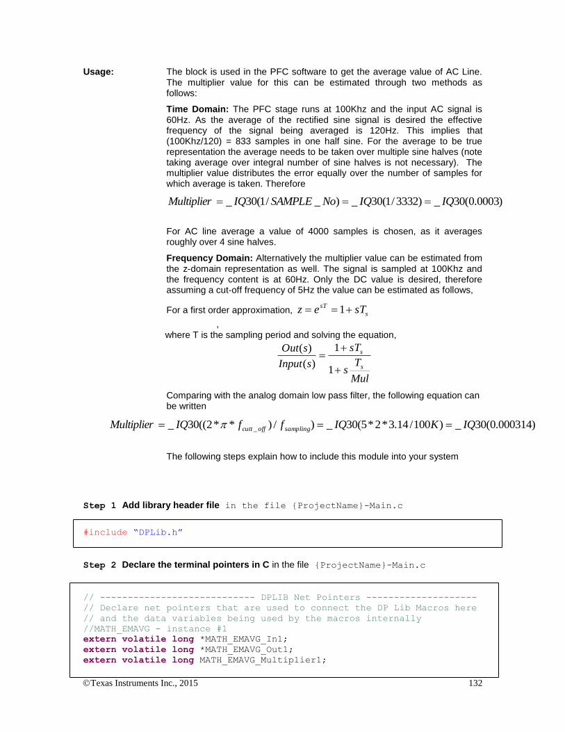
Texas Instruments Inc., 2015 132
Usage: The block is used in the PFC software to get the average value of AC Line. The multiplier value for this can be estimated through two methods as follows:
Time Domain: The PFC stage runs at 100Khz and the input AC signal is 60Hz. As the average of the rectified sine signal is desired the effective frequency of the signal being averaged is 120Hz. This implies that (100Khz/120) = 833 samples in one half sine. For the average to be true representation the average needs to be taken over multiple sine halves (note taking average over integral number of sine halves is not necessary). The multiplier value distributes the error equally over the number of samples for which average is taken. Therefore
)0003.0(30_)3332/1(30_)_/1(30_ IQIQNoSAMPLEIQMultiplier
For AC line average a value of 4000 samples is chosen, as it averages roughly over 4 sine halves.
Frequency Domain: Alternatively the multiplier value can be estimated from the z-domain representation as well. The signal is sampled at 100Khz and the frequency content is at 60Hz. Only the DC value is desired, therefore assuming a cut-off frequency of 5Hz the value can be estimated as follows,
For a first order approximation, s
sT sTez 1
, where T is the sampling period and solving the equation,
Mul
Ts
sT
sInput
sOut
s
s
1
1
)(
)(
Comparing with the analog domain low pass filter, the following equation can be written
)000314.0(30_)100/14.3*2*5(30_)/)**2((30_ _ IQKIQffIQMultiplier samplingoffcutt
The following steps explain how to include this module into your system
Step 1 Add library header file in the file {ProjectName}-Main.c
#include “DPLib.h”
Step 2 Declare the terminal pointers in C in the file {ProjectName}-Main.c
// ---------------------------- DPLIB Net Pointers --------------------
// Declare net pointers that are used to connect the DP Lib Macros here
// and the data variables being used by the macros internally
//MATH_EMAVG - instance #1
extern volatile long *MATH_EMAVG_In1;
extern volatile long *MATH_EMAVG_Out1;
extern volatile long MATH_EMAVG_Multiplier1;
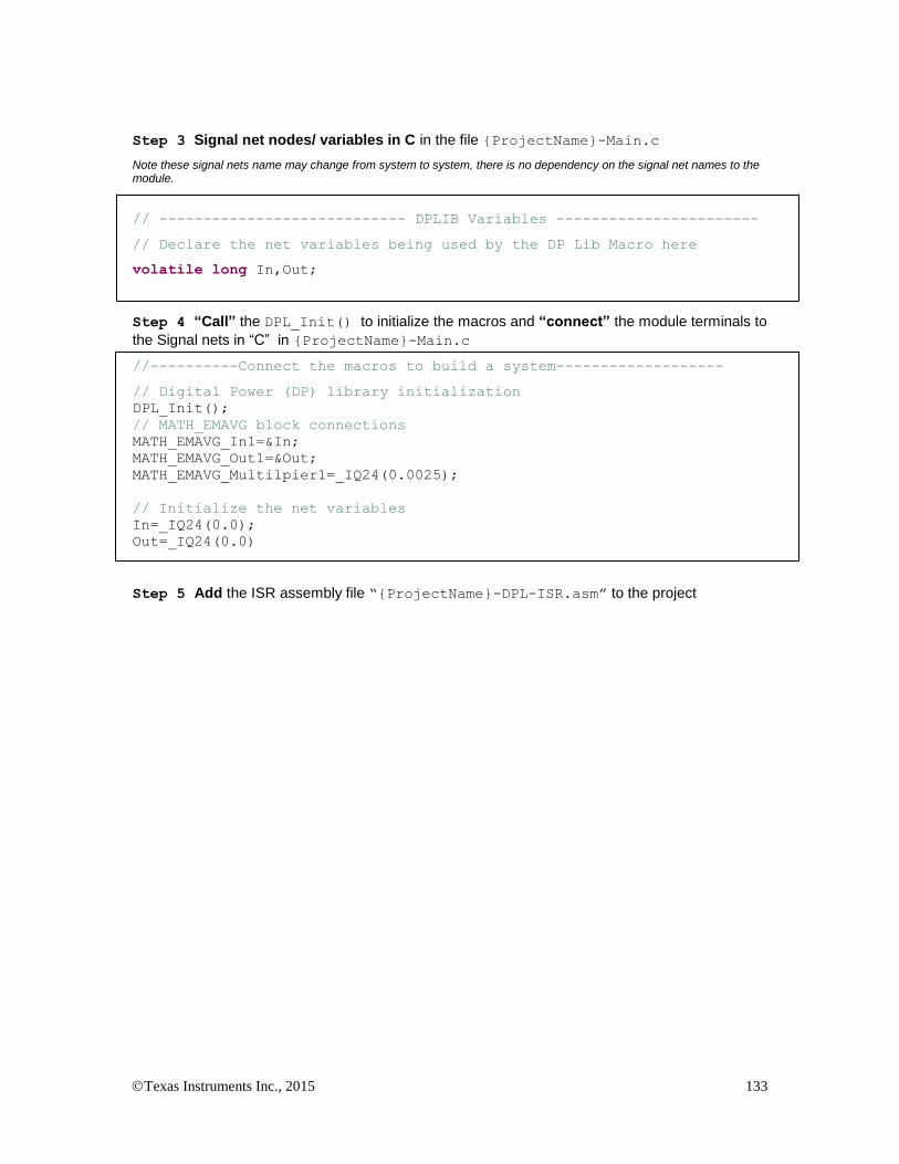
Texas Instruments Inc., 2015 133
Step 3 Signal net nodes/ variables in C in the file {ProjectName}-Main.c
Note these signal nets name may change from system to system, there is no dependency on the signal net names to the module.
// ---------------------------- DPLIB Variables -----------------------
// Declare the net variables being used by the DP Lib Macro here
volatile long In,Out;
Step 4 “Call” the DPL_Init() to initialize the macros and “connect” the module terminals to
the Signal nets in “C” in {ProjectName}-Main.c
//----------Connect the macros to build a system-------------------
// Digital Power (DP) library initialization
DPL_Init();
// MATH_EMAVG block connections
MATH_EMAVG_In1=&In;
MATH_EMAVG_Out1=&Out;
MATH_EMAVG_Multilpier1=_IQ24(0.0025);
// Initialize the net variables
In=_IQ24(0.0);
Out=_IQ24(0.0)
Step 5 Add the ISR assembly file “{ProjectName}-DPL-ISR.asm” to the project

Texas Instruments Inc., 2015 134
Step 6 Include the macro’s assembly file in the {ProjectName}-DPL-ISR.asm
;Include files for the Power Library Macro's being used by the system
.include "MATH_EMAVG.asm"
Step 7 Instantiate the INIT macro in assembly (this is one-time pass through code) inside the
C-callable DPL_Init() function which is defined in{ProjectName}-DPL-ISR.asm
;Macro Specific Initialization Functions
MATH_EMAVG_INIT 1 ; MATH_EMAVG Initialization
Step 8 Call the run time macro in assembly inside the C-callable function DPL_ISR() which
is the looped or ISR code. The function is defined in{ProjectName}-DPL-ISR.asm
;”Call” the Run macro
MATH_EMAVG_INIT 1 ; Run the MATH_EMAVG Macro
Step 9 Include the memory sections in the {DeviceName}-{RAM/FLASH}-
{ProjectName}.CMD. Note that the net pointers and the internal data are forced to be placed
in a single data page by use of the .usect directive in the source file of the module.
/*MATH_EMAVG sections*/
MATH_EMAVG_Section : > RAML2 PAGE = 1
Module Net Definition:
Net name (:n: is the instance number)
Description Format
Acceptable Range of Variable or of the Variable being pointed to
MATH_EMAVG_In:n: Input Pointer Pointer to 32 bit fixed input data location storing the data that needs to averaged
Q24: [0, 1)
MATH_EMAVG_Out:n: Output Pointer Pointer to 32 bit fixed output data location where the computed average is stored
Q24: [0, 1)
MATH_EMAVG_Multiplier:n: Internal Data Data Variable storing the weighing factor for the exponential average.
Q30:[0,1)
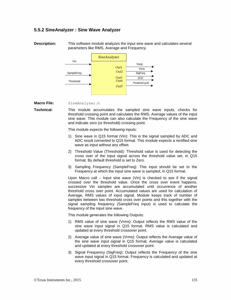
Texas Instruments Inc., 2015 135
5.5.2 SineAnalyzer : Sine Wave Analyzer
Description: This software module analyzes the input sine wave and calculates several parameters like RMS, Average and Frequency.
Vin
VrmsIn
SineAnalyzer
SampleFreq
Out1
Out3Out4
Out2
Vavg
SigFreq
ZCD
ThresholdPositiveCycle
Out5
Macro File: SineAnalyzer.h
Technical: This module accumulates the sampled sine wave inputs, checks for threshold crossing point and calculates the RMS, Average values of the input sine wave. This module can also calculate the Frequency of the sine wave and indicate zero (or threshold) crossing point.
This module expects the following inputs:
1) Sine wave in Q15 format (Vin): This is the signal sampled by ADC and ADC result converted to Q15 format. This module expects a rectified sine wave as input without any offset.
2) Threshold Value (Threshold): Threshold value is used for detecting the cross over of the input signal across the threshold value set, in Q15 format. By default threshold is set to Zero.
3) Sampling Frequency (SampleFreq): This input should be set to the Frequency at which the input sine wave is sampled, in Q15 format.
Upon Macro call – Input sine wave (Vin) is checked to see if the signal crossed over the threshold value. Once the cross over event happens, successive Vin samples are accumulated until occurrence of another threshold cross over point. Accumulated values are used for calculation of Average, RMS values of input signal. Module keeps track of number of samples between two threshold cross over points and this together with the signal sampling frequency (SampleFreq input) is used to calculate the frequency of the input sine wave.
This module generates the following Outputs:
1) RMS value of sine wave (Vrms): Output reflects the RMS value of the sine wave input signal in Q15 format. RMS value is calculated and updated at every threshold crossover point.
2) Average value of sine wave (Vrms): Output reflects the Average value of the sine wave input signal in Q15 format. Average value is calculated and updated at every threshold crossover point.
3) Signal Frequency (SigFreq): Output reflects the Frequency of the sine wave input signal in Q15 format. Frequency is calculated and updated at every threshold crossover point.

Texas Instruments Inc., 2015 136
Vin
In
SineAnalyzer – RMS
calculation
Vrms
ZCDSampled Rect. ACRMS Value of sine
wave
Threshold
N
Vin 2
2Vin
Vin
In
SineAnalyzer – Avg
calculation
Vavg
ZCDSampled Rect. ACAverage Value of
sine wave
Threshold
NVinVin
Vin
In
SineAnalyzer –
Frequency calculation
SigFreq
ZCDSampled Rect. ACFrequency of sine
wave
Threshold
nSamples
++ nSamples
eqSamplingFr
Usage: This section explains how to use this module.
Step 1 Add library header file in the file {ProjectName}-Main.c
#include “SineAnalyzer.h”
Step 2 Add extern declaration in the header file {ProjectName}-includes.h
// Object declaration in the header file
extern SineAnalyzer sine_mainsV;
Step 3 Creation of objects in C file {ProjectName}-Main.c
// Creating instances of the data type with pre-initialized objects
SineAnalyzer sine_mainsV = SineAnalyzer_DEFAULTS;
Step 4 Input initialization in C file {ProjectName}-Main.c
//sine analyzer initialization
sine_mainsV.Vin=0;
sine_mainsV.SampleFreq=_IQ15(20000.0); // Sampling rate 20KHz
sine_mainsV.Threshold=_IQ15(0.02); // Threshold set to 0.02
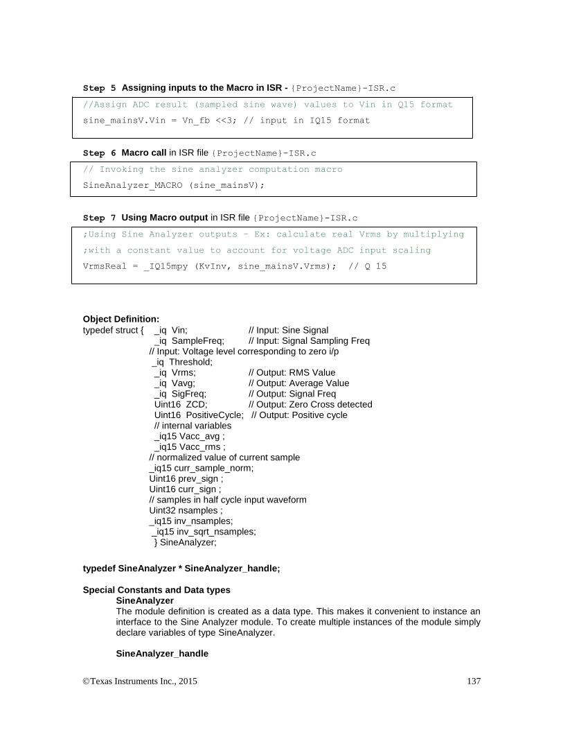
Texas Instruments Inc., 2015 137
Step 5 Assigning inputs to the Macro in ISR - {ProjectName}-ISR.c
//Assign ADC result (sampled sine wave) values to Vin in Q15 format
sine_mainsV.Vin = Vn_fb <<3; // input in IQ15 format
Step 6 Macro call in ISR file {ProjectName}-ISR.c
// Invoking the sine analyzer computation macro
SineAnalyzer_MACRO (sine_mainsV);
Step 7 Using Macro output in ISR file {ProjectName}-ISR.c
;Using Sine Analyzer outputs – Ex: calculate real Vrms by multiplying
;with a constant value to account for voltage ADC input scaling
VrmsReal = _IQ15mpy (KvInv, sine_mainsV.Vrms); // Q 15
Object Definition:
typedef struct { _iq Vin; // Input: Sine Signal _iq SampleFreq; // Input: Signal Sampling Freq
// Input: Voltage level corresponding to zero i/p _iq Threshold;
_iq Vrms; // Output: RMS Value _iq Vavg; // Output: Average Value _iq SigFreq; // Output: Signal Freq Uint16 ZCD; // Output: Zero Cross detected Uint16 PositiveCycle; // Output: Positive cycle // internal variables _iq15 Vacc_avg ; _iq15 Vacc_rms ;
// normalized value of current sample _iq15 curr_sample_norm; Uint16 prev_sign ;
Uint16 curr_sign ; // samples in half cycle input waveform
Uint32 nsamples ; _iq15 inv_nsamples; _iq15 inv_sqrt_nsamples; } SineAnalyzer;
typedef SineAnalyzer * SineAnalyzer_handle;
Special Constants and Data types
SineAnalyzer The module definition is created as a data type. This makes it convenient to instance an interface to the Sine Analyzer module. To create multiple instances of the module simply declare variables of type SineAnalyzer. SineAnalyzer_handle
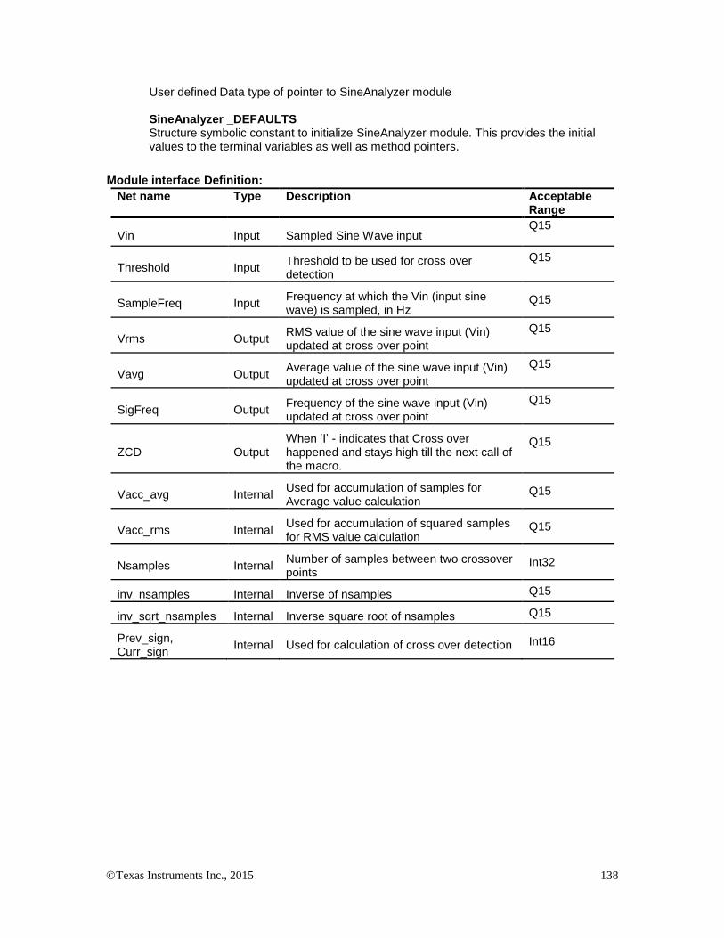
Texas Instruments Inc., 2015 138
User defined Data type of pointer to SineAnalyzer module SineAnalyzer _DEFAULTS Structure symbolic constant to initialize SineAnalyzer module. This provides the initial values to the terminal variables as well as method pointers.
Module interface Definition:
Net name Type Description Acceptable Range
Vin Input Sampled Sine Wave input Q15
Threshold Input Threshold to be used for cross over detection
Q15
SampleFreq Input Frequency at which the Vin (input sine wave) is sampled, in Hz
Q15
Vrms Output RMS value of the sine wave input (Vin) updated at cross over point
Q15
Vavg Output Average value of the sine wave input (Vin) updated at cross over point
Q15
SigFreq Output Frequency of the sine wave input (Vin) updated at cross over point
Q15
ZCD Output When ‘I’ - indicates that Cross over happened and stays high till the next call of the macro.
Q15
Vacc_avg Internal Used for accumulation of samples for Average value calculation
Q15
Vacc_rms Internal Used for accumulation of squared samples for RMS value calculation
Q15
Nsamples Internal Number of samples between two crossover points
Int32
inv_nsamples Internal Inverse of nsamples Q15
inv_sqrt_nsamples Internal Inverse square root of nsamples Q15
Prev_sign, Curr_sign
Internal Used for calculation of cross over detection Int16

Texas Instruments Inc., 2015 139
5.6 Utilities
5.6.1 DLOG_4ch : Four Channel Data Logger
Description: This software module performs data logging to emulate an oscilloscope in software to graphically observe system variables. The data is logged in the buffers and viewed as graphs in graph windows to observe the system variables as waveforms.
DLOG_4ch
i1Ptr buff1Ptr
Size
i2Ptr
i3Ptr
i4Ptr TrigValPreScalar
buff2Ptr
buff3Ptr
buff4Ptr
DBUFF1
DBUFF2
DBUFF3
DBUFF4
Var1
Var2
Var3
Var4
DLOG_4ch_i1Ptr
DLOG_4ch_i2Ptr
DLOG_4ch_i3Ptr
DLOG_4ch_i4Ptr
DLOG_4ch_buff1Ptr
DLOG_4ch_buff2Ptr
DLOG_4ch_buff3Ptr
DLOG_4ch_buff4Ptr
Macro File: DLOG_4ch.asm
Technical: This software module performs data logging over data stored in Q24 format,
pointed to by four pointers DLOG_4ch_i1Ptr, DLOG_4ch_i2Ptr,
DLOG_4ch_i3Ptr and DLOG_4ch_i4Ptr. The input variable value is
then scaled to Q15 format and stored in arrays pointed to by DLOG_4ch_buff1Ptr, DLOG_4ch_buff2Ptr, DLOG_4ch_buff3Ptr
and DLOG_4ch_buff4Ptr.
The data logger is triggered at the positive edge of the value pointed by the
pointer DLOG_4ch_i1Ptr. The trigger value is programmable by writing the
Q24 trigger value to the module variable DLOG_4ch_TrigVal.
The size of the data logger has to be specified using the DLOG_4ch_Size
module variable.
The module can be configured to log data every n number module call, by
specifying a scalar value in variable DLOG_4ch_PreScalar. The following
example illustrates how best these values be chose using a PFC algorithm example.
Usage: When using the DLOG module for observing system variables in the PFC algorithm it is desirable to observe the logged variable over a multiple line AC period to verify working of the algorithm. The PFC algorithm is typically run at 100Khz, the AC signal has a frequency of 60Hz. Taking memory constraints into account it is reasonable to expect 200 words array for each buffer.
The DLOG module each time in the ISR i.e. at 100Khz, if the samples are logged every call the buffer size required to observe one sine period is 100KHz/60Hz ~= 1666. With memory constraints having four buffers like this is not feasible. 200 words array for each buffer would be a reasonable buffer size that would fit into the RAM of the device. Thus samples need to taken every alternate number or pre scalar number of times. Assuming two sine periods need to be observed in the watch window,
33.8)*60(
100Pr
BufferSizeHz
KhzeScalar
The trigger Value is used to trigger the logging of data at a positive edge
around the trigger value of the data pointed to by DLOG_4CH_iPtr.

Texas Instruments Inc., 2015 140
Step 1 Add library header file in the file {ProjectName}-Main.c
#include “DPLib.h”
Step 2 Declare the terminal pointers in C in the file {ProjectName}-Main.c
// ---------------------------- DPLIB Net Pointers --------------------
// Declare net pointers that are used to connect the DP Lib Macros here
// and the data variables being used by the macros internally
//DLOG_4ch - instance #1
extern volatile long *DLOG_4ch_i1Ptr;
extern volatile long *DLOG_4ch_i2Ptr;
extern volatile long *DLOG_4ch_i3Ptr;
extern volatile long *DLOG_4ch_i4Ptr;
extern volatile int16 *DLOG_4ch_buff1Ptr;
extern volatile int16 *DLOG_4ch_buff2Ptr;
extern volatile int16 *DLOG_4ch_buff3Ptr;
extern volatile int16 *DLOG_4ch_buff4Ptr;
extern volatile long DLOG_4ch_TrigVal;
extern volatile int16 DLOG_4ch_PreScalar;
extern volatile int16 DLOG_4ch_Size;
Step 3 Declare signal net nodes/ variables in C in the file {ProjectName}-Main.cc Note
that the DLOG_SIZE is a #define in the {ProjectName}-Settings.h and can be modified if needed.
Note these signal nets name may change from system to system, there is no dependency on the signal net names to the module.
// ---------------------------- DPLIB Variables -----------------------
// Declare the net variables being used by the DP Lib Macro here
#pragma DATA_SECTION(DBUFF1,"DLOG_BUFF");
#pragma DATA_SECTION(DBUFF2,"DLOG_BUFF");
#pragma DATA_SECTION(DBUFF3,"DLOG_BUFF");
#pragma DATA_SECTION(DBUFF4,"DLOG_BUFF");
volatile int16 DBUFF1[DLOG_SIZE];
volatile int16 DBUFF2[DLOG_SIZE];
volatile int16 DBUFF3[DLOG_SIZE];
volatile int16 DBUFF4[DLOG_SIZE];
Step 4 “Call” the DPL_CLAInit() to initialize the macros and “connect” the module
terminals to the signal nets in “C” in {ProjectName}-Main.c
//----------Connect the macros to build a system-------------------
// Digital Power (DP) library initialization

Texas Instruments Inc., 2015 141
DPL_Init();
// DLOG block connections
// Store address of the system variables that need to be logged
// In the example below PFC algorithm variables are logged
DLOG_4ch_i1Ptr =&VacLineRect;
DLOG_4ch_i2Ptr =&InvAvgSqr;
DLOG_4ch_i3Ptr =&PFCIcmd;
DLOG_4ch_i4Ptr =&VacLineAvg;
// Point the BuffPtr to the buffer location
DLOG_4ch_buff1Ptr =DBUFF1;
DLOG_4ch_buff2Ptr =DBUFF2;
DLOG_4ch_buff3Ptr =DBUFF3;
DLOG_4ch_buff4Ptr =DBUFF4;
// Setup Size, Trigger Value and Pre Scalar
DLOG_4ch_TrigVal = _IQ(0.1);
DLOG_4ch_PreScalar = 25;
DLOG_4ch_Size=DLOG_SIZE;
// Zero the buffers
DLOG_4ch_BuffInit(DBUFF1, DLOG_SIZE);
DLOG_4ch_BuffInit(DBUFF2, DLOG_SIZE);
DLOG_4ch_BuffInit(DBUFF3, DLOG_SIZE);
DLOG_4ch_BuffInit(DBUFF4, DLOG_SIZE);
Step 5 Add the ISR assembly file “{ProjectName}-DPL-ISR.asm” to the project
Step 6 Include the macro’s assembly file in the {ProjectName}-DPL-ISR.asm
;Include files for the Power Library Macro's being used by the system
.include "DLOG_4ch.asm"
Step 7 Instantiate the INIT macro in assembly (this is one-time pass through code) inside the
C-callable DPL_Init() function which is defined in{ProjectName}-DPL-ISR.asm
;Macro Specific Initialization Functions
DLOG_4ch_INIT 1 ; DLOG_4CH Initialization
Step 8 Call the run time macro in assembly inside the C-callable function DPL_ISR() which
is the looped or ISR code. The function is defined in{ProjectName}-DPL-ISR.asm
;”Call” the Run macro
DLOG_4ch 1 ; Run the DLOG_4CH Macro
Step 9 Include the memory sections in the {DeviceName}-{RAM/FLASH}-
{ProjectName}.CMD. Note that the net pointers and the internal data are forced to be placed
in a single data page by use of the .usect directive in the source file of the module.
/*DLOG_4ch sections*/
DLOG_4ch_Section : > dataRAM PAGE = 1

Texas Instruments Inc., 2015 142
Module Net Definition:
Net name (:n: is the instance number)
Description Format
Acceptable Range of Variable or of the Variable being pointed to
DLOG_4ch_i1Ptr, DLOG_4ch_i2Ptr DLOG_4ch_i3Ptr DLOG_4ch_i4Ptr
Input Pointers Pointer to 32 bit input data location storing the data that needs to logged.
Q24: [0, 1)
DLOG_4ch_buff1Ptr, DLOG_4ch_buff2Ptr DLOG_4ch_buff3Ptr DLOG_4ch_buff4Ptr
Output Pointer
Pointer to 16 bit output data buffer location where the logged data is stored after scaling input data from Q24 to Q15.
Q15: [0, 1)
DLOG_4ch_Size Internal Data 16 bit integer data storing the buffer size being used by the DLOG module
Q0
DLOG_4ch_PreScalar Internal Data 16 bit integer data storing the pre scalar value
Q0
DLOG_4ch_TrigVal Internal Data Q24 data variable storing the trigger value for the DLOG module.
Q24:[0,1)
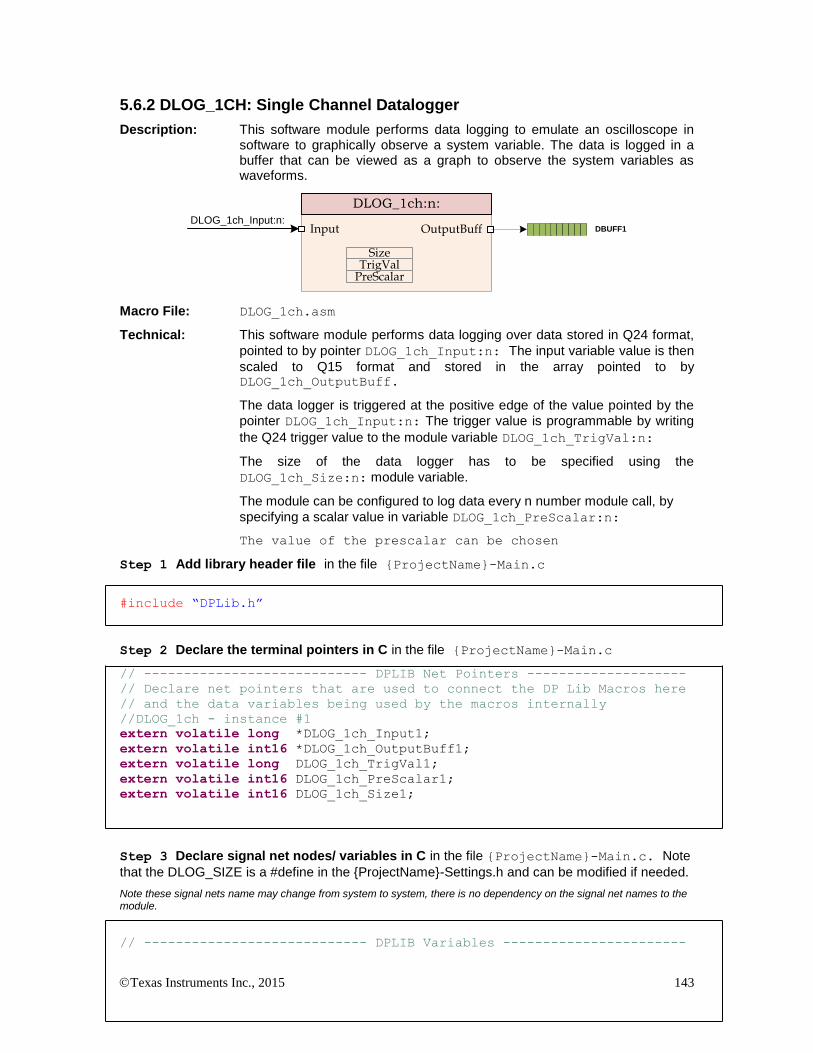
Texas Instruments Inc., 2015 143
5.6.2 DLOG_1CH: Single Channel Datalogger
Description: This software module performs data logging to emulate an oscilloscope in software to graphically observe a system variable. The data is logged in a buffer that can be viewed as a graph to observe the system variables as waveforms.
DLOG_1ch:n:
Input OutputBuff
SizeTrigValPreScalar
DBUFF1DLOG_1ch_Input:n:
Macro File: DLOG_1ch.asm
Technical: This software module performs data logging over data stored in Q24 format,
pointed to by pointer DLOG_1ch_Input:n: The input variable value is then
scaled to Q15 format and stored in the array pointed to by DLOG_1ch_OutputBuff.
The data logger is triggered at the positive edge of the value pointed by the
pointer DLOG_1ch_Input:n: The trigger value is programmable by writing
the Q24 trigger value to the module variable DLOG_1ch_TrigVal:n:
The size of the data logger has to be specified using the
DLOG_1ch_Size:n: module variable.
The module can be configured to log data every n number module call, by
specifying a scalar value in variable DLOG_1ch_PreScalar:n:
The value of the prescalar can be chosen
Step 1 Add library header file in the file {ProjectName}-Main.c
#include “DPLib.h”
Step 2 Declare the terminal pointers in C in the file {ProjectName}-Main.c
// ---------------------------- DPLIB Net Pointers --------------------
// Declare net pointers that are used to connect the DP Lib Macros here
// and the data variables being used by the macros internally
//DLOG_1ch - instance #1
extern volatile long *DLOG_1ch_Input1;
extern volatile int16 *DLOG_1ch_OutputBuff1;
extern volatile long DLOG_1ch_TrigVal1;
extern volatile int16 DLOG_1ch_PreScalar1;
extern volatile int16 DLOG_1ch_Size1;
Step 3 Declare signal net nodes/ variables in C in the file {ProjectName}-Main.c. Note
that the DLOG_SIZE is a #define in the {ProjectName}-Settings.h and can be modified if needed.
Note these signal nets name may change from system to system, there is no dependency on the signal net names to the module.
// ---------------------------- DPLIB Variables -----------------------

Texas Instruments Inc., 2015 144
// Declare the net variables being used by the DP Lib Macro here
#pragma DATA_SECTION(DBUFF,"DLOG_BUFF");
volatile int16 DBUFF[DLOG_SIZE];
Step 4 “Call” the DPL_CLAInit() to initialize the macros and “connect” the module
terminals to the Signal nets in “C” in {ProjectName}-Main.c
//----------Connect the macros to build a system-------------------
// Digital Power (DP) library initialization
DPL_Init();
// DLOG block connections
// Store address of the system variables that need to be logged
DLOG_1ch_Input1 =&VacLineRect;
// Point the BuffPtr to the buffer location
DLOG_1ch_OutputBuff1 =DBUFF;
// Setup Size, Trigger Value and Pre Scalar
DLOG_1ch_TrigVal1 = _IQ(0.1);
DLOG_1ch_PreScalar1 = 25;
DLOG_1ch_Size1=DLOG_SIZE;
// Zero the buffers
DLOG_BuffInit(DBUFF, DLOG_SIZE);
Step 5 Add the ISR assembly file “{ProjectName}-DPL-ISR.asm” to the project
Step 6 Include the macro’s assembly file in the {ProjectName}-DPL-ISR.asm
;Include files for the Power Library Macro's being used by the system
.include "DLOG_1ch.asm"
Step 7 Instantiate the INIT macro in assembly (this is one-time pass through code) inside the
C-callable DPL_Init() function which is defined in{ProjectName}-DPL-ISR.asm
;Macro Specific Initialization Functions
DLOG_1ch_INIT 1 ; DLOG_1CH Initialization
Step 8 Call run time macro in assembly inside the C-callable function DPL_ISR() which is the
looped or ISR code. The function is defined in{ProjectName}-DPL-ISR.asm
;”Call” the Run macro
DLOG_1ch 1
Step 9 Include the memory sections in the {DeviceName}-{RAM/FLASH}-
{ProjectName}.CMD. Note that the net pointers and the internal data are forced to be placed
in a single data page by use of the .usect directive in the source file of the module.
/*DLOG_1ch sections*/
DLOG_1ch_Section : > dataRAM PAGE = 1

Texas Instruments Inc., 2015 145
Module Net Definition:
Net name (:n: is the instance number)
Description Format
Acceptable Range of Variable or of the Variable being pointed to
DLOG_1ch_Input:n: Input Pointer Pointer to 32 bit input data location storing the data that needs to logged.
Q24: [0, 1)
DLOG_1ch_OutputBuff:n: Output Pointer
Pointer to 16 bit output data buffer location where the logged data is stored after scaling input data from Q24 to Q15.
Q15: [0, 1)
DLOG_1ch_Size:n: Internal Data 16 bit integer data storing the buffer size being used by the DLOG module
Q0
DLOG_1ch_PreScalar:n: Internal Data 16 bit integer data storing the pre scalar value
Q0
DLOG_1ch_TrigVal:n: Internal Data Q24 data variable storing the trigger value for the DLOG module.
Q24:[0,1)
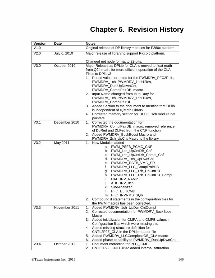
Texas Instruments Inc., 2015 146
Chapter 6. Revision History
Version Date Notes
V1.0 --- Original release of DP library modules for F280x platform.
V2.0 July 6, 2010 Major release of library to support Piccolo platform. Changed net node format to 32-bits.
V3.0 October 2010 Major Release as DPLib for CLA is moved to float math from Q24 math, for more efficient operation of the CLA. Fixes to DPlibv2 1. Period value corrected for the PWMDRV_PFC2PhiL,
PWMDRV_1ch, PWMDRV_1chHiRes, PWMDRV_DualUpDownCnt, PWMDRV_ComplPairDB, macro
2. Input Name changed from In to Duty for PWMDRV_1ch, PWMDRV_1chHiRes, PWMDRV_ComplPairDB
3. Added Section to the document to mention that DPlib is independent of IQMath Library
4. Corrected memory section for DLOG_1ch module net pointers
V3.1 December 2010 1. Corrected the documentation for PWMDRV_ComplPairDB, macro, removed reference of DbRed and DbFed from the CNF function
2. Added PWMDRV_BuckBoost Macro and PWMDRV_2ch_UpCnt Macro to the library
V3.2 May 2011 1. New Modules added a. PWM_PSFB_PCMC_CNF b. PWM_1ch_UpCntDB_Cnf c. PWM_1ch_UpCntDB_Compl_Cnf d. PWMDRV_1ch_UpDwnCnt e. PWMDRV_PSFB_VMC_SR f. PWMDRV_LLC_ComplPairDB g. PWMDRV_LLC_1ch_UpCntDB h. PWMDRV_LLC_1ch_UpCntDB_Compl i. DACDRV_RAMP j. ADCDRV_8ch k. SineAnalyzer l. PFC_BL_ICMD m. PFC_INVRMS_SQR
2. Compound if statements in the configuration files for the PWM macros has been corrected.
V3.3 November 2011 1. Added PWMDRV_1ch_UpDwnCntCompl 2. Corrected documentation for PWMDRV_BuckBoost
Macro 3. Added initialization for CMPA and CMPB values in
Configuration files which were missing this 4. Added missing structure definition for
CNTL2P2Z_CLA in the DPLib header file 5. Added PWMDRV_LLCComplpairDB_CLA macro 6. Added phase capability to PWMDRV_DualUpDwnCnt
V3.4 October 2012 1. Document correction for PFC_ICMD 2. CNTL2P2Z, CNTL3P3Z added internal saturation

Texas Instruments Inc., 2015 147
correction for operation when the compensator output needs to go negative
3. Added PWM_1chHiResUpDwnCnt Macro 4. Changed Folder structure to accommodate for CLA
and C base macros 5. Corrected the initialization part of the ADCnDRV
Macro, removed the right shift when loading the data page pointer
6. Change PWM period value for the CNF files to Uint16 7. CLA_C support added to the library for devices it is
applicable
V3.5 Feb 2015 1. Added PWM_1ch_UpCntDB_ActivHIC_Cnf 2. Fixed documentation bugs
Recommended