We reserve the right to modify technical specif ications without prior notice.83053700cUK– Translation of the operating manual © Alpha-InnoTec GmbH
Professional
operat ing Manual
Heat pumps
Brine / Water
sWP
UK
2We reserve the right to modify technical specif ications without prior notice.83053700cUK– Translation of the operating manual © Alpha-InnoTec GmbH
Please read firstThis operating manual provides important information on the handling of the unit. It is an integral part of the product and must be stored so that it is accessible in the immediate vicinity of the unit. It must remain available throughout the entire service life of the unit. It must be handed over to subsequent owners or users of the unit.
In addition to this operating manual, you must also have the operating manual for the heating and heat pump regulator and the operating manual for your heat pump.
Read the operating manual before working on or operating the unit. This applies in particular to the chapter on safety. Always follow all instructions completely and without restrictions.
It is possible that this operating manual may contain instructions that seem incomprehensible or unclear. In the event of any questions or if any details are unclear, contact the factory customer service department or the manufacturer’s local partner.
Since this operating manual was written for several different models of the unit, always comply with the parameters for the respective model.
This operating manual is intended only for persons assigned to work on or operate the unit. Treat all constituent parts confidentially. The information contained herein is protected by copyright. No part of this manual may be reproduced, transmitted, copied, stored in electronic data systems or translated into another language, either wholly or in part, without the express written permission of the manufacturer.
symbolsThe following symbols are used in the operating manual. They have the following meaning:
Information for operators.
Information or instructions for qualified personnel.
Danger! Indicates a direct impending danger
resulting in severe injuries or death.
WarnIng! Indicates a potentially dangerous situation
that could result in serious injuries or death.
CautIon! Indicates a potentially dangerous situation
that could result in medium or slight injuries.
CautIon. Indicates a potentially dangerous situation, which
could result in property damage.
note. Emphasized information.
€ energy savIng tIp Indicates suggestions that help to save energy,
raw materials and costs.
Reference to other sections of the operating manual.
Reference to other documents of the manufacturer.

3
Content
INfoRmATIoN foR USERS ANd qUAlIfIEd pERSoNNEl
plEASE REAd fIRST ..................................................................2
SymbolS .....................................................................................2
INTENdEd USE ..........................................................................4
dISclAImER................................................................................4
Ec coNfoRmITy .....................................................................4
SAfETy .........................................................................................4
cUSTomER SERvIcE ................................................................5
WARRANTy / GUARANTEE ....................................................5
dISpoSAl ....................................................................................5
INfoRmATIoN foR USERS
opERATING pRINcIplE of HEAT pUmpS ................5
AREA of UTIlISATIoN ............................................................5
HEAT mETERING .......................................................................6
opERATIoN ................................................................................6
cARE of THE UNIT ..................................................................6
mAINTENANcE of THE UNIT ..............................................6cleaning and flushing of unit components ........................7
mAlfUNcTIoNS .......................................................................7
INSTRUcTIoNS foR qUAlIfIEd pERSoNNEl
ScopE of dElIvERy ..................................................7
INSTAllATIoN ..........................................................................8Installation area .....................................................................8Transport to installation location ......................................8Installation ..............................................................................9
INSTAllATIoN of THE HydRAUlIc coNNEcTIoNS 10buffer tank ...........................................................................10domestic water heating .....................................................10domestic hot water tank ..................................................10Installing the housing ..........................................................12
ElEcTRIcAl coNNEcTIoNS .............................................14
INSTAllATIoN of THE coNTRol ElEmENT ...............16
flUSHING ANd fIllING THE UNIT .................................. 17flushing and filling the heat source ................................... 17flushing and filling the heating circuit .............................. 17
INSUlATING THE HydRAUlIc coNNEcTIoNS ..........19
commISSIoNING ...................................................................19
dISmANTlING .........................................................................20
TEcHNIcAl dATA / ScopE of dElIvERySWp 371 – 691, SWp 291H - 561H ..................................22
Heating capacity/cop / power consumption / heat pump pressure loss
SWp 371 ...............................................................................24SWp 451 ...............................................................................25SWp 581 ...............................................................................26SWp 691 ...............................................................................27SWp 291H ............................................................................28SWp 561H ............................................................................29
dImENSIoNAl dRAWINGS ANd INSTAllATIoN plANS
SWp 371 - SWp 691dimensional drawings - moving dimensions ...................30dimensional drawings with housing ................................31
SWp 291H - SWp 561dimensional drawings - moving dimensions ...................32dimensional drawings with housing ................................33
Installation plansSWp 371 – 691, SWp 291H - 561H ..................................34SWp 371 – 691, SWp 291H - 561H ..................................35
TERmINAl dIAGRAm .............................................................36
cIRcUIT dIAGRAmSSWp 371, SWp 451 .............................................................37SWp 581, SWp 691, SWp 561H ....................................... 40SWp 291H ............................................................................43
AppENdIx
Ec dEclARATIoN of coNfoRmITy ..............................46
cUSTomER SERvIcE
Addresses for service .........................................................50
We reserve the right to modify technical specif ications without prior notice.83053700cUK– Translation of the operating manual © Alpha-InnoTec GmbH

4We reserve the right to modify technical specif ications without prior notice.83053700cUK– Translation of the operating manual © Alpha-InnoTec GmbH
intended useThe unit may be used only for the intended purpose. This means:
• for heating.
• for domestic water heating.
• for cooling (active + passive through external hydraulics)
The unit may be operated only within its technical parameters.
overview “Technical data / scope of delivery”.
note. Notify the responsible power supply company of
the use of a heat pump or heat pump system.
DisclaimerThe manufacturer is not liable for losses resulting from any use of the unit which is not its intended use.
The manufacturer’s liability also expires:
• If work is carried out on the unit and its components contrary to the instructions in this operating manual.
•If work is improperly carried out on the unit and its components.
• If work is carried out on the unit which is not described in this operating manual, and this work has not been explicitly approved by the manufacturer in writing.
• If the unit or components in the unit have been altered, modified or removed without the explicit written consent of the manufacturer.
eC conformityThe unit bears the cE mark of conformity.
Ec declaration of conformity
safetyThe unit is safe to operate for its intended use. The construction and design of the unit conform to current state of the art standards, all relevant dIN/vdE regulations and all relevant safety regulations.
Every person who performs work on the unit must have read and understood the operating manual prior to starting any work. This also applies if the respective person has already worked with such a unit or a similar unit or has been trained by the manufacturer.
Every person who performs work on the unit must comply with the applicable accident prevention and safety regulations. This applies in particular to the wearing of personal safety gear.
Danger! risk of fatal injury due to electric shock! all electrical connections must be carried
out by qualified electricians only.
Before opening the unit, disconnect the system from the power supply and prevent it from being switched back on!
WarnIng! only qualified personnel (trained heating,
cooling and refrigerant engineers and electricians) may carry out work on the unit and its components.
WarnIng! observe safety labels on and in the unit.
WarnIng! unit contains refrigerants! Leaking refrigerant could result in
personal injury or material damage. therefore:
– switch off unit– thoroughly ventilate installation room– notify the manufacturer’s authorised
service centre
CautIon. for safety reasons: Never disconnect the unit from the power
supply, unless the unit is being opened.

5We reserve the right to modify technical specif ications without prior notice.83053700cUK– Translation of the operating manual © Alpha-InnoTec GmbH
Customer servicefor technical information please contact your local heating engineer or the manufacturer’s local partner.
overview “customer service”.
Warranty / Guaranteefor warranty and guarantee conditions, please refer to the purchase documents.
note. please contact your dealer about all matters
concerning warranties and guarantees.
DisposalWhen decommissioning the old unit, always comply with local applicable laws, directives and standards concerning the recovery, recycling and disposal of materials and components of cooling units.
“dismantling”.
operating principle of heat pumps
Heat pumps operate on the same principle as a refrigerator: same technology, only with reversed benefits. The refrigerator extracts heat from foods, which is released into the room through fins on the back.
The heat pump extracts heat from our environment: air, earth or ground water. The extracted heat is conditioned in the unit and supplied to the heating water. Even when it is extremely cold outside, the heat pump draws enough heat to heat a house.
Example: drawing of a brine/water heat pump with floor heating:
4/4 = usable energyapprox. 3/4 = environmental energyapprox. 1⁄4 = external electrical
energy
area of utilisationTaking into consideration the ambient conditions, limits of application and the applicable regulations, every heat pump can be utilised in new or existing heating systems.
overview “Technical data / scope of delivery”.
6We reserve the right to modify technical specif ications without prior notice.83053700cUK– Translation of the operating manual © Alpha-InnoTec GmbH
Heat meteringIn addition to proof of the unit’s efficiency, the EEWaermeG also requires heat metering (hereafter referred to as HqR). Heat metering is mandatory for air/water heat pumps. Heat metering for brine/water and water/water heat pumps only have to be installed for a flow temperature ≥ 35 °c. The heat metering must record the total thermal energy released (heating and domestic hot water) in the building. In heat pumps with heat metering, the analysis is carried out by the regulator. The regulator displays the thermal energy discharged in the heating system in kWh.
operationyour decision to purchase a heat pump or a heat pump system is a long-term contribution to protecting the environment through low emissions and reduced primary energy use.
To ensure that your heat pump or heat pump system operates efficiently and ecologically, the following are especially important:
€ energy savIng tIp Avoid unnecessarily high flow temperatures.
A lower flow temperature on the hot water side increases the efficiency of the system.
€ energy savIng tIp preferably use purge ventilation. compared to
continuously open windows, it is better to air rooms by fully opening windows for a short period, two to three times a day (so-called “rapid” or “purge” ventilation); this reduces energy consumption and your heating bill.
you can operate and control the heat pump system with the control element of the heating and heat pump regulator.
note. make sure that the control settings are correct.
operating manual of the heating and heat pump regulator.
Care of the unitThe outer surfaces of the unit can be cleaned with a damp cloth and standard cleaning products.
do not use cleaning or care products that contain abrasives, acids and/or chlorine. Such products would destroy the surfaces and could also damage the technical components of the unit.
Maintenance of the unitThe cooling circuit of the heat pump requires no regular maintenance.
According to EU regulation (Ec) 842/2006 of may 17, 2006, leak inspections and maintenance of a log book are required for certain heat pumps!
The criteria for conducting leak inspections and maintaining a log book are based on the hermetic impermeability of the cooling circuit and the refrigerant capacity of the heat pump! No log book is required for heat pumps with a refrigerant capacity of < 3kg. With all other heat pumps, the log book is included with all other delivered materials.
log book for heat pumps, Section “Information on use of the log book”.
The components of the heating circuit and the heat source (valves, expansion vessels, circulating pumps, filters, dirt traps) should be inspected and cleaned as needed - at the very least annually - by qualified personnel (heating or cooling system fitters).
It is best to arrange a maintenance agreement with a heating installation company. The company will arrange for the required maintenance at regular intervals.
7We reserve the right to modify technical specif ications without prior notice.83053700cUK– Translation of the operating manual © Alpha-InnoTec GmbH
CleaningandflushingofunitComponents
CautIon! unit components may be cleaned
and flushed only by customer service personnel authorised by the manufacturer. use only liquids recommended by the manufacturer.
Flushing of the liquefier with chemical cleaning agents must be followed by neutralisation of residue and intensive flushing with water. always observe the technical data of the manufacturer of the heat exchanger.
MalfunctionsIn the event of a fault, you can read out the cause of the fault from the diagnostic program of the heating and heat pump regulator.
operating manual of the heating and heat pump regulator.
WarnIng! only customer service personnel
authorised by the manufacturer may carry out service and repair work on the components of the unit.
overview “customer service”.
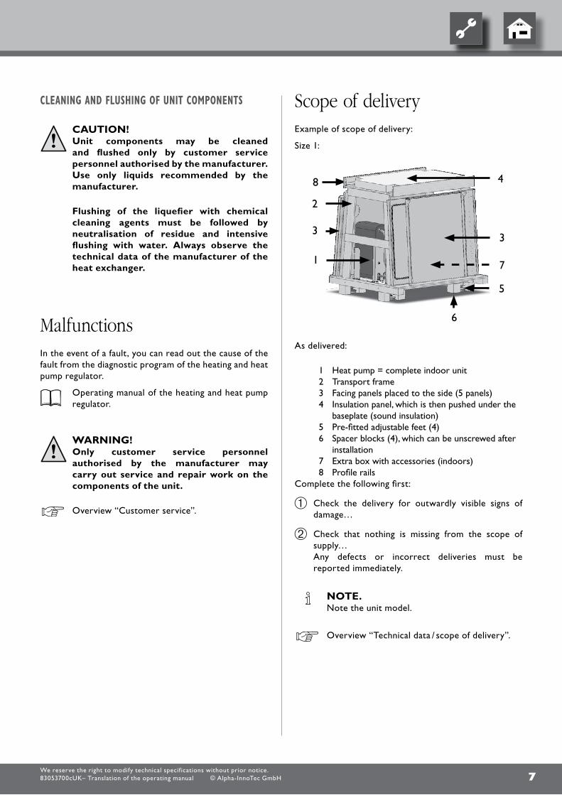
scope of deliveryExample of scope of delivery:
Size 1:
As delivered:
1 Heat pump = complete indoor unit2 Transport frame3 facing panels placed to the side (5 panels)4 Insulation panel, which is then pushed under the
baseplate (sound insulation)5 pre-fitted adjustable feet (4)6 Spacer blocks (4), which can be unscrewed after
installation7 Extra box with accessories (indoors)8 profile rails
complete the following first:
check the delivery for outwardly visible signs of damage…
check that nothing is missing from the scope of supply…
Any defects or incorrect deliveries must be reported immediately.
note. Note the unit model.
overview “Technical data / scope of delivery”.

8We reserve the right to modify technical specif ications without prior notice.83053700cUK– Translation of the operating manual © Alpha-InnoTec GmbH
installationobserve the following when performing all work:
note. Always comply with the applicable local accident
prevention regulations, statutory regulations, ordinances, guidelines and directives.
WarnIng! the heat pump or heat pump system
may only be installed and assembled by qualified personnel!
note. observe the sound levels of the respective
model.
overview “Technical data / scope of delivery”, “Sound” section.
installationarea
CautIon. Install the heat pump only indoors. The installation room must be frost-free and
dry.
WarnIng! please note and follow the respective
relevant local standards, directives and regulations applicable, especially the minimum volume necessary depending on the refrigerant capacity of the relevant heat pump system (en 378-1).
Refrigerant limit
R 134a 0.25 kg/m³
R 404A 0.48 kg/m³
R 407c 0.31 kg/m³
R 410A 0.44 kg/m³
overview “Technical data / scope of delivery”, “General unit data” section.
Minimum volume = Refrigerant capacity [kg]
limit [kg/m³]
note. If several heat pumps of the same type
are installed, only one heat pump must be considered.
If several heat pumps of different types are installed, the heat pump with the largest refrigerant capacity must be considered.
transporttoinstallationloCation
before transporting the heat pump to the final installation location the packaging and wooden frame can be dismantled.
To do this, remove the facing panels on the long sides, undo the wooden boards and remove the two machine screws (m8) in each of the sides.
you can now lift the unit with the help of a pallet truck or fork lift truck and transport it to its final installation location.
note. The unit has ground clearance for easy access
from all sides
note. The baseplate is 76 cm wide, so that the heat
pump can be transported through a standard door opening.

9We reserve the right to modify technical specif ications without prior notice.83053700cUK– Translation of the operating manual © Alpha-InnoTec GmbH
note. Keep the components enclosed in the scope of
delivery in a safe place until the assembly.
Always comply with the following safety information during transport:
CautIon! Wear safety gloves.
WarnIng! several people are required to transport
the unit. Do not underestimate the weight of the unit.
overview “Technical data / scope of delivery”, “General unit data” section.
CautIon! Make sure to secure unit against slipping
during transport.
CautIon. Never use components and hydraulic
connections on the unit for purposes of transport.
do not damage the hydraulic connections under any circumstances.
CautIon. do not tilt the unit more than a maximum of 45°
(in any direction).
installation
WarnIng! several people are required to install the
unit.
note. Take into account the size of the unit.
overview “Technical data / scope of delivery”, “General unit data” section.
note. Always follow the installation plan for the
respective model. Note the size and minimum clearances.
Installation plan for respective model.
CautIon. The heat pump must be installed on a firm,
horizontal surface. make sure that the foundation is designed for the weight of the heat pump.
do not use a rigid foam boiler pedestal!
overview “Technical data/scope of delivery”, “General unit data” section.
note. Set up the unit so that the operating side is
accessible at all times!
CautIon. do not tilt the unit more than a maximum of 45°
(in any direction).
lower the basic heat pump module on the 4 wooden transport blocks in its final installation location. Now use the vibration-decoupling, adjustable machine feet to align the unit horizontally. Ensure the distance from the finished floor level to the top of the heat pump baseplate is 170 mm. lock this setting by locking the nuts.
The four transport blocks (each with 2 universal wood screws) must then be removed.

10We reserve the right to modify technical specif ications without prior notice.83053700cUK– Translation of the operating manual © Alpha-InnoTec GmbH
CautIon. connect the unit to the heating circuit according
to the hydraulic diagram for the respective model.
“Hydraulic connection” instructions.
CautIon. The heat source system must be designed
according to the specifications of the planning manual.
planning manual and “Hydraulic connection” documents.
note: check to make sure that the diameters and
lengths of the pipes for the heating circuit and the heat source are sufficiently dimensioned.
note: circulating pumps, which pump the volume flow
through the heat pump, must be designed as multi-stage pumps. They must at least provide the minimum throughput rate required for your model.
In the case of heat source pumps, the viscosity of the brine liquid must also be taken into account!
overview “Technical data / scope of delivery”, “Heat circuit” and “Heat source” sections.
CautIon. The hydraulic system must be equipped with
a buffer tank, the required volume of which depends on the model of your unit.
CautIon. When installing the connections, always secure
the connections on the unit against twisting, in order to prevent damage to the components inside the unit.
installation of the hydraulic connections
Buffertank
The hydraulic connection of the heat pump requires a buffer tank in the heating circuit. The required volume of the buffer tank is calculated based on the following formula:
vbuffer tank =minimum flow rate of heat circuit volume flow / hour
10
for the minimum flow rate of the heat circuit volume flow, see overview “Technical data/Scope of delivery”, “Heating circuit” section.
domestiCwaterheating
The domestic water heating with the heat pump requires an additional hot water circuit, parallel to the heating circuit. When installing, make sure that the domestic hot water charge is not fed through the buffer tank of the heating circuit.
“Hydraulic connection” instructions.
domestiChotwatertank
If the heat pump is to be used for domestic water heating, you must integrate special domestic hot water tanks in the heat pump system. choose a storage volume so that the required quantity of hot water is available even during a power cut.
note: The heat exchanger surface of the domestic hot
water tank must be dimensioned so that the heating capacity of the heat pump is transferred with minimum spread.
We offer a variety of domestic hot water tanks for you to choose from. They are optimised for use with your heat pump.
11We reserve the right to modify technical specif ications without prior notice.83053700cUK– Translation of the operating manual © Alpha-InnoTec GmbH
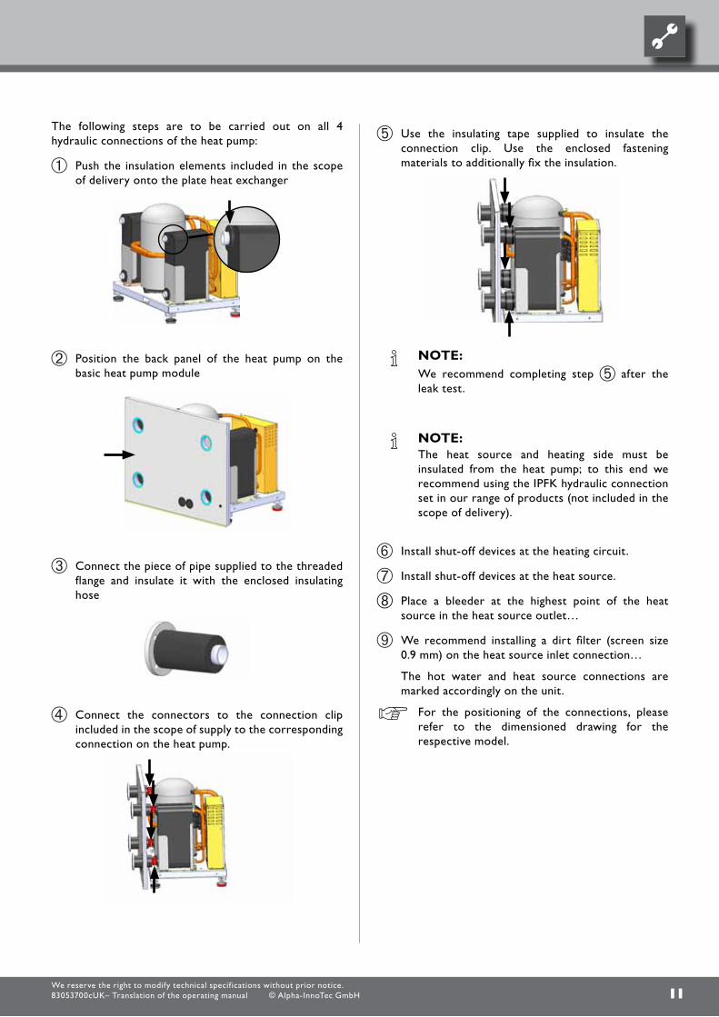
The following steps are to be carried out on all 4 hydraulic connections of the heat pump:
push the insulation elements included in the scope of delivery onto the plate heat exchanger
position the back panel of the heat pump on the basic heat pump module
connect the piece of pipe supplied to the threaded flange and insulate it with the enclosed insulating hose
connect the connectors to the connection clip included in the scope of supply to the corresponding connection on the heat pump.
Use the insulating tape supplied to insulate the connection clip. Use the enclosed fastening materials to additionally fix the insulation.
note: We recommend completing step after the
leak test.
note: The heat source and heating side must be
insulated from the heat pump; to this end we recommend using the IpfK hydraulic connection set in our range of products (not included in the scope of delivery).
Install shut-off devices at the heating circuit.
Install shut-off devices at the heat source.
place a bleeder at the highest point of the heat source in the heat source outlet…
We recommend installing a dirt filter (screen size 0.9 mm) on the heat source inlet connection…
The hot water and heat source connections are marked accordingly on the unit.
for the positioning of the connections, please refer to the dimensioned drawing for the respective model.

12We reserve the right to modify technical specif ications without prior notice.83053700cUK– Translation of the operating manual © Alpha-InnoTec GmbH
installingthehousing
note. Remove the protective film from all facing panels.
note. The screws for installing the heat pump housing
are included in the scope of delivery.
position the insulation included in the scope of delivery under the baseplate.
note. before screwing on the side panels, feed the patch
cable and + lIN bus cable through the rear panel!
see “electrical connection work”
Screw the two side panels onto the back panel using 3 screws for each:
mount the profile rail onto the front of the unit, between the two side panels, using 2 screws for each side.
1 profile rail2 Screw
Align the facing with the baseplate as shown in the following sketch
28
28
28
Secure and fix the facing on the profile rail using the fastening materials included in the scope of delivery (2 x 10mm anchors and 2 x m8 hanger bolts). Twist the hanger bolt into the floor up to the start of the thread.
1 hanger bolt with anchor
Align the insulating board under the unit with the
middle of the unit (see ).
fix the housing cover onto the rear panel (5 screws):
and the two side panels (2 screws each) onto the front:

13We reserve the right to modify technical specif ications without prior notice.83053700cUK– Translation of the operating manual © Alpha-InnoTec GmbH
The front panel can now be hung into the clips provided at the bottom
and locked by means of the two quarter-turn screws.
Glue the insulating half-shells included in the scope of delivery around the pipe pieces in the rear panel.

14We reserve the right to modify technical specif ications without prior notice.83053700cUK– Translation of the operating manual © Alpha-InnoTec GmbH
1 Electrical switch cabinet
open the unit’s electrical switch cabinet: Undo the 6 screws slightly, in order to unhook the
cover panel by lifting it slightly…
Several openings are provided at the back of the unit for passing through the cables:
note. When laying the cable, ensure that unshielded
power supply cables and shielded cables (lIN bus) are laid separately from each other.
note. lIN bus length may not be increased. However,
they can be shortened.
for further details, see “installation plan”
1 Electric cable penetration
2 penetration, lIN bus and patch cable for luxtronik 2.0 regulator
electrical connectionsThe following applies to all work to be done:
Danger! risk of fatal injury due to electric shock! all electrical connections must be carried
out by qualified electricians only.
Before opening the unit, disconnect the system from the power supply and prevent it from being switched back on!
WarnIng! During installation and while carrying out
electrical work, comply with the relevant en-, vDe and/or local safety regulations.
Comply with technical connection requirements of the responsible power supply company (if required by the latter)!
note. All cables must be fed through the openings in
the back panel!
The front panel is hung in at the bottom and is held in place at the top by 2 quarter-turn screws.
1 quarter-turn screws
open the quarter-turn screws of the front panel by turning them through 90° anticlockwise…
lift out front panel and set aside in a safe place…
15We reserve the right to modify technical specif ications without prior notice.83053700cUK– Translation of the operating manual © Alpha-InnoTec GmbH
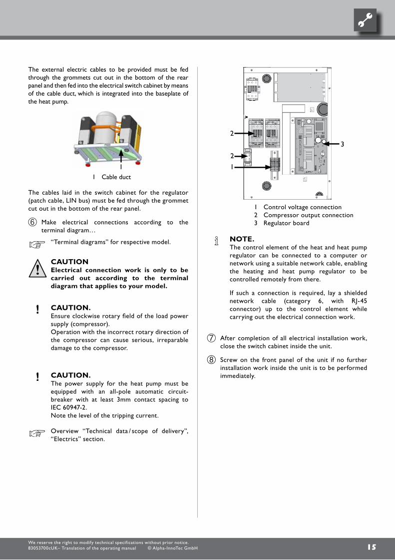
The external electric cables to be provided must be fed through the grommets cut out in the bottom of the rear panel and then fed into the electrical switch cabinet by means of the cable duct, which is integrated into the baseplate of the heat pump.
1 cable duct
The cables laid in the switch cabinet for the regulator (patch cable, lIN bus) must be fed through the grommet cut out in the bottom of the rear panel.
make electrical connections according to the terminal diagram…
“Terminal diagrams” for respective model.
CautIon electrical connection work is only to be
carried out according to the terminal diagram that applies to your model.
CautIon. Ensure clockwise rotary field of the load power
supply (compressor). operation with the incorrect rotary direction of
the compressor can cause serious, irreparable damage to the compressor.
CautIon. The power supply for the heat pump must be
equipped with an all-pole automatic circuit-breaker with at least 3mm contact spacing to IEc 60947-2.
Note the level of the tripping current.
overview “Technical data / scope of delivery”, “Electrics” section.
1 control voltage connection2 compressor output connection3 Regulator board
note. The control element of the heat and heat pump
regulator can be connected to a computer or network using a suitable network cable, enabling the heating and heat pump regulator to be controlled remotely from there.
If such a connection is required, lay a shielded network cable (category 6, with RJ-45 connector) up to the control element while carrying out the electrical connection work.
After completion of all electrical installation work, close the switch cabinet inside the unit.
Screw on the front panel of the unit if no further installation work inside the unit is to be performed immediately.

16We reserve the right to modify technical specif ications without prior notice.83053700cUK– Translation of the operating manual © Alpha-InnoTec GmbH
connection of patch cable and lIN bus cable to the regulator (via the strain relief):
1 patch cable to the network link2 lIN bus to the regulator board in the unit3 patch cable to the regulator
board in the unit
If the work on the heat pump regulator has been completed, the cover can be clipped onto the wall bracket.
+ =
note. A connection to a computer or a network can
be installed via the left bushing on the bottom of the control element, thus allowing the heating and heat pump regulator to be controlled remotely. This requires that a shielded network cable was laid up to the heat pump regulator during the electrical connection work.
operating manual for the heating and heat pump regulator, version “qualified heating engineers”, “Web server” section.
note. The network cable can be exchanged at any
time. In order to be able to connect it, the screen must first be removed.
installation of the control element
note. Note the distance between the control element
and the unit.
for further details, see “installation plan”
control element for wall-mounting
fasten the wall bracket using the assembly materials included in the scope of delivery.
There are 4 fixing hooks on the back of the control element.
Hang the control element on the wall bracket using the 4 fixing hooks and push down until it latches into position.
1 Shielded terminal for lIN bus cable/strain relief
2 Strain relief
17We reserve the right to modify technical specif ications without prior notice.83053700cUK– Translation of the operating manual © Alpha-InnoTec GmbH
flushingandfillingtheheatingCirCuit
waterqualityofthefillandadditionalwaterinhotwaterheatingsystemsaCCordingtoVdi2035partiandii
Use of modern, energy-efficient heat pump systems is becoming increasingly widespread. Their ingenious technology enables these systems to achieve very good efficiencies. The decreasing space available for heat generators has led to the development of compact units with increasingly smaller cross-sections and high capacities. This means the complexity of the systems and the material diversity are also increasing, which plays an important role especially in their corrosion behaviour. Alpha InnoTec ensures continuous technological advances, but all these technical refinements require the system to be operated with correctly filled heating water. The heating water not only affects the efficiency of the system, but also the life of the heat generator and the heating components of a system.
The guide values of vdI 2035 part I and part II must therefore be complied with as minimum requirements for proper operation of the systems. our practical experience has shown that the safest and most trouble-free running of the systems is achieved with so-called low-salt operation.
vdI 2035 part I gives important information and recommendations regarding scaling and its prevention in heating and domestic hot water heating systems.
vdI 2035 part II primarily deals with the requirements for reducing heating water corrosion in hot water heating systems.
prinCiplesofpartiandpartii
The occurrence of scaling and corrosion damage in hot water heating systems is low, if
- proper planning and commissioning is carried out
- the system is closed in corrosion terms
- adequately dimensioned pressurising is integrated
- the guide values for the heating water are complied with
- and regular servicing and maintenance are carried out.
A system log should be kept, in which the relevant planning data is entered (vdI 2035).
flushing and filling the unit
CautIon. The system must be absolutely free from air
before commissioning.
flushingandfillingtheheatsourCe
contamination and deposits in the heat source can cause malfunctions.
CautIon. before flushing and filling the heat source the
drain pipe of the safety valve must be connected - Important: do not discharge into the drains (anti-freeze mixture)!.
proceed as follows:
flush heat source system thoroughly.
Thoroughly mix the anti-freeze, available as an accessory, with water with the required ratio. Add only anti-freeze mixed with water to the heat source.
CautIon. The concentration of anti-freeze in the water
must be at the level specified for your model.
overview “Technical data / scope of delivery”, “Heat source” section.
check the concentration of the anti-freeze in the mixture…
fill heat source with the anti-freeze mixture…
bleed the heat source.

18We reserve the right to modify technical specif ications without prior notice.83053700cUK– Translation of the operating manual © Alpha-InnoTec GmbH
damagethatCanoCCurinCaseofnon-ComplianCe
- malfunctions and the failure of components (e.g. pumps, valves)
- Internal and external leaks (e.g. from heat exchangers)
- cross-section reduction and blockaging of components (e.g. heat exchanger, pipes, pumps)
- material fatigue
- Gas bubbles and gas cushion formation (cavitation)
- Negative effect on heat transfer (formation of coatings, deposits) and associated noises (e.g. boiling noises, flow noises)
limesCale–theenergykiller
filling with untreated drinking water inevitably leads to the precipitation of all calcium as scale. The consequence: limescale deposits form on the heat transfer surfaces of the heating. The efficiency falls and the energy costs rise. A rule of thumb is that 1 millimetre of limescale deposit causes an energy loss of 10%. In extreme cases it can even cause damage to the heat exchangers.
watersofteningtoVdi2035–parti
If the water is softened before the heating is filled, in accordance with the vdI 2035 guidelines, no scale can form. This effectively and permanently prevents limescale deposits and the resulting negative effects on the entire heating system.
Corrosion–anunderestimatedproBlem
vdI 2035, part II, deals with the problem of corrosion. Softening the heating water can prove to be insufficient. The pH value can significantly exceed the limit of 10. pH values higher than 11 can set in, which even damage rubber seals. The vdI 2035, part 1 guidelines are fulfilled, however, vdI 2035, part 2 suggests a pH value between 8.2 and maximum 10.
If aluminium materials are used, which is the case in many modern heating systems, a pH value of 8.5 must not be exceeded, because otherwise there is a threat of corrosion – and aluminium is attacked without the presence of oxygen. Therefore, apart from softening the heating fill and additional water, the heating water should also be appropriately conditioned. This is the only way to comply with the vdI 2035 requirements and the recommendations and installation instructions of the heat pump manufacturer.
part 2 of vdI 2035 also points out the reduction in total salt content (conductivity). The risk of corrosion is far lower if deionised water is used than is the case if the system is operated with salty, i.e. softened water.
Even if the water has been softened beforehand, it contains dissolved, corrosion-promoting salts, which act as electrolytes due to the use of different materials in the heating system and therefore accelerate corrosion processes. This can ultimately result in pitting.
onthesafesidewithlow-saltoperation
The problems listed above do not occur at all with low-salt operation, as neither corrosive salts such as sulphates, chlorides and nitrates nor alkalising sodium hydrogen carbonate are in the heating water. The corrosive properties of deionised water are very low and in addition, fur cannot form in the boiler. This is the ideal approach for closed heating circuits, in particular, because low oxygen input into the heating circuit can also be tolerated.
In general, when the system is filled with deionised water, the pH value sets itself within the ideal range due to „self-alkalinisation“. If necessary, a pH value of 8.2 can be very easily alkalised by adding chemicals. In this way, optimum protection of the entire heating system is achieved.
monitoring
Analytical recording and monitoring of the relevant water values and the added active conditioning substances is of decisive importance. Therefore, they should be monitored regularly using appropriate water test equipment.
CautIon. before flushing and filling the heating circuit, the
drain pipe of the safety valve must be connected.
flush heating circuit system thoroughly.
fill heating circuit…
bleed heating circuit.
19We reserve the right to modify technical specif ications without prior notice.83053700cUK– Translation of the operating manual © Alpha-InnoTec GmbH
insulating the hydraulic connections
note. Insulate the heating circuit and the heat source
according to relevant local standards and guidelines.
check all hydraulic connections for leaks. perform leak test…
Insulate all connections, vibration isolation, connections and pipes of the heating circuit and the heat source. Insulate the heat source so that it is vapour-diffusion tight.
Commissioning Thoroughly check the installation and work through
the items on the general checklist…
“General checklist”.
The installation inspection will prevent damage to the heat pump system that could be caused by improperly executed work.
Ensure that…
• the clockwise rotary field of the load power supply (compressor) is ensured.
• The heat pump installation and assembly is according to the requirements in this operating manual.
• The electrical installation work has been carried out properly.
• The power supply for the heat pump must be equipped with a three-phase automatic circuit-breaker with at least 3 mm contact spacing to IEc 60947-2. Note the level of the tripping current.
• The heating circuit and the heat source are flushed, filled and bled thoroughly.
• All valves and shut-off devices of the heating circuit are open.
• All valves and shut-off devices of the heat source are open.
• All pipe systems and components of the system are sealed.
carefully fill out and sign the completion report for heat pump systems…
“completion report for heat pump systems”.
In Germany: Send completion report for heat pump systems
and general checklist to the manufacturer’s factory customer service department.
outside of Germany: Send completion report for heat pump systems
and general checklist to the manufacturer’s local partner.
overview “customer service”.
The heat pump system will be commissioned by customer service personnel authorized by the manufacturer. There is a fee for commissioning!
20We reserve the right to modify technical specif ications without prior notice.83053700cUK– Translation of the operating manual © Alpha-InnoTec GmbH
Dismantling
Danger! risk of fatal injury due to electric shock! electrical connections may be installed
only by qualified electricians.
Before opening the unit, disconnect the system from the power supply and prevent it from being switched back on!
WarnIng! only qualified heating or cooling system
personnel are allowed to remove the unit from the system and dismantle the unit.
CautIon. The anti-freeze mixture of the heat source must
not be allowed to enter the sewer system. collect anti-freeze mixture and dispose of
properly.
CautIon. Recycle or ensure proper disposal of unit
components, refrigerants and oil according to the relevant regulations, standards and guidelines.
remoValoftheBufferBattery
CautIon. before scrapping the heating and heat pump
regulator, remove the buffer battery on the processor board. The battery can be pushed out using a screwdriver. dispose of battery and electronic components in an environmentally friendly way.

21We reserve the right to modify technical specif ications without prior notice.83053700cUK– Translation of the operating manual © Alpha-InnoTec GmbH

22
Device designationHeat pump type Brine/Water ı Air/Water ı Water/Water • relevant ı — not relevant
Installation location Indoors ı Outdoors • relevant ı — not relevant
Conformity CE
Power data Heating power/COP at
B0/W35 Standard point as per EN14511 2 Compressors 1 Compressor
kW ı … kW ı …
B0/W45 Standard point as per EN14511 2 Compressors 1 Compressor
kW ı … kW ı …
B7/W35 Standard point as per EN14511 2 Compressors 1 Compressor
kW ı … kW ı …
B0/W50 Standard point as per EN14511 2 Compressors 1 Compressor
kW ı … kW ı …
Operating limits Heat circuit °C
Heat source °C
Additional operating points …
Noise Sound pressure level at 1m gap around the machine averaged (in free field) dB(A)
Sound power level as per EN12102 dB
Heat source Volumetric flow: minimum throughput ı nominal throughput ı maximum throughput l/h
Pressure loss in heat pump ∆p ı Volumetric flow bar ı l/h
Recommended brine circulating pump …
Total compression of the recommended pump at nominal brine volumetric flow bar ı l/h
Antifreeze Monoethylene glycol
Minimum concentration ı frostproof to % ı °C
Heat circuit Volumetric flow: minimum throughput ı nominal throughput ı maximum throughput l/h
Pressure loss in heat pump ∆p ı Volumetric flow bar ı l/h
Free compression of heat pump ∆p ı Volumetric flow bar ı l/h
Temperature spread for B0/W35 K
General device data Earth (see dimensional diagram for the size indicated) Size
Total weight kg
Extra weight of construction unit 1 kg
Extra weight of construction unit 2 kg
Connections Heat circuit …
Heat source …
Refrigerant Refrigerant type ı Filling capacity … ı kg
Electrics Voltage code ı All-pole circuit breaker for pump *) … ı A
Voltage code ı Control voltage circuit breaker *) … ı A
Voltage code ı Electrical heating element circuit breaker *) ı A
Heat pump Effective power consumption in the normal point B0/W35 as per EN14511: Power consumption ı Current consumption ı cosφ
kW ı A ı …
Maximum machine current within the operating limits A
Starting current: direct ı with slow-starter A ı A
Protection type IP
Power of electrical heating element 3 ı 2 ı 1-phase kW ı kW ı kW
Components Circulating pump for heat circuit at nominal throughput: Power consumption ı Current consumption kW ı A
Circulating pump for heat source at nominal throughput: Power consumption ı Current consumption kW ı A
Setting range for motor protection switch of heat source circulating pump A
Passive cooling function Data only for devices with ID K: Cooling power at nominal volumetric flow rates (15 °C heat source, 25 °C hot water) kW
Safety devices Safety assembly for heat circuit ı Safety assembly for heat source in scope of supply: • yes — no
Heating and heat pump control in scope of supply: • yes — no
Electronic soft-starter integrated: • yes — no
Expansion vessels Heat source: Scope of supply ı Volume ı Supply pressure • yes — no ı l ı bar
Heat circuit: Scope of supply ı Volume ı Supply pressure • yes — no ı l ı bar
Overflow valve integrated: • yes — no
Vibration isolation Heat circuit ı Heat source in scope of supply: • yes — no
UK813198a *) Observe local regulations n.n. = cannot be demonstrated
We reserve the right to modify technical specif ications without prior notice.83053700cUK– Translation of the operating manual © Alpha-InnoTec GmbH
technical data / scope of delivery

23
SWP561H• ı — ı —
• ı —•
- 53,8 ı 4,50
- 52,9 ı 3,80
- 65,9 ı 5,20
- 52,1 ı 3,10
20 - 64 -5 - 25B0/W70
4459
9400 ı 12600 ı 191000,16 ı 12600
——•
25 ı -134400 ı 8900 ı 11200
0,12 ı 8900— ı —
5,01
521——
DN50 DIN2566DN50 DIN2566R134a ı 12,8
3~/PE/400V/50Hz ı C501~/N/PE/230V/50Hz ı B16
— ı —12,0 ı 27,80 ı 0,63
45,6310 ı 120
20— ı — ı —
— ı —— ı —
——
— ı —••
— ı —— ı —
——
813433
SWP691• ı — ı —
• ı —•
- 68,5 ı 4,60
- 66,1 ı 3,60
- 84,1 ı 5,40
- 64,6 ı 2,90
20 - 60 -5 - 25B0/W65
4459
13000 ı 17300 ı 210000,16 ı 17300
——•
25 ı -135700 ı 11300 ı 14200
0,12 ı 11300— ı —
5,21
484——
DN50 DIN2566DN50 DIN2566R410A ı 13,4
3~/PE/400V/50Hz ı C501~/N/PE/230V/50Hz ı B16
— ı —14,9 ı 28,14 ı 0,75
48,5272 ı 110
20— ı — ı —
— ı —— ı —
——
— ı —••
— ı —— ı —
——
813431a
SWP291H• ı — ı —
• ı —•
- 27,5 ı 4,30
- 26,7 ı 3,40
- 33,2 ı 5,10
- 25,9 ı 2,70
20 - 64 -5 - 25B4/W70
4358
4900 ı 6500 ı 78000,16 ı 6500
——•
25 ı -132400 ı 4700 ı 5900
0,12 ı 4700— ı —
5,01
319——
DN50 DIN2566DN50 DIN2566
R134a ı 6,73~/PE/400V/50Hz ı C40
1~/N/PE/230V/50Hz ı B16— ı —
6,4 ı 14,92 ı 0,6234
174 ı 10020
— ı — ı —— ı —— ı —
——
— ı —••
— ı —— ı —
——
813432a
SWP581• ı — ı —
• ı —•
- 57,6 ı 4,80
- 55,8 ı 3,80
- 71,1 ı 5,80
- 54,1 ı 3,00
20 - 60 -5 - 25B0/W65
4257
10200 ı 13600 ı 163000,15 ı 13600
——•
25 ı -134900 ı 9700 ı 12200
0,12 ı 9700— ı —
5,11
441——
DN50 DIN2566DN50 DIN2566R410A ı 11,2
3~/PE/400V/50Hz ı C501~/N/PE/230V/50Hz ı B16
— ı —12,0 ı 22,16 ı 0,76
40225 ı 110
20— ı — ı —
— ı —— ı —
——
— ı —••
— ı —— ı —
——
813430a
SWP451• ı — ı —
• ı —•
- 45,0 ı 4,80
- 42,7 ı 3,70
- 55,0 ı 5,70
- 41,1 ı 2,90
20 - 58 -5 - 25B0/W65
4156
8100 ı 10800 ı 130000,15 ı 10800
——•
25 ı -133900 ı 7800 ı 9400
0,12 ı 7800— ı —
5,01
385——
DN50 DIN2566DN50 DIN2566R410A ı 8,2
3~/PE/400V/50Hz ı C401~/N/PE/230V/50Hz ı B16
— ı —9,4 ı 18,28 ı 0,72
34174 ı 88
20— ı — ı —
— ı —— ı —
——
— ı —••
— ı —— ı —
——
813429a
SWP371• ı — ı —
• ı —•
- 37,2 ı 4,80
- 35,8 ı 3,70
- 45,4 ı 5,60
- 34,8 ı 2,90
20 - 57 -5 - 25B3/W65
3954
6900 ı 9200 ı 111000,16 ı 9200
——•
25 ı -133200 ı 6400 ı 8000
0,12 ı 6400— ı —
5,01
371——
DN50 DIN2566DN50 DIN2566
R410A ı 7,23~/PE/400V/50Hz ı C32
1~/N/PE/230V/50Hz ı B16— ı —
7,8 ı 13,97 ı 0,831
140 ı 8520
— ı — ı —— ı —— ı —
——
— ı —••
— ı —— ı —
——
813428a
We reserve the right to modify technical specif ications without prior notice.83053700cUK– Translation of the operating manual © Alpha-InnoTec GmbH

24 Bezeichnung:
Seite: 1/1
Zeichnungsnummer:
Datei: 823077 Leistungs-Druckverlustkurven SWP371.xls
Leistungs-DruckverlustkurvenSWP371
Legende: DE823025L
823077a
∆p„
∆p”
“”
Druckverlust Heizkreis
Volumenstrom Heizwasser
Volumenstrom Wärmequelle
Temperatur Wärmequelle
Heizleistung
Leistungsaufnahme
Coeffiicient of performance / Leistungszahl
a/PEP007-2011/Garthe/19.12.2011 823077a
Änd./Ä.M./Ersteller/Datum
-/PEP007-2011/Garthe/29.07.2011
Druckverlust Wärmequelle
“„
Temp„
Qh
Pe
COP
20
30
40
50
60
70
80
-10 -5 0 5 10 15 20 25 30
Temp„ (°C)
Qh (kW)
35°C
45°C
55°C
65°C
1
2
3
4
5
6
7
8
-10 -5 0 5 10 15 20 25 30
Temp„ (°C)
COP
6
11
16
-10 -5 0 5 10 15 20 25 30
Temp„ (°C)
Pe (kW)
0,0
0,1
0,2
0,3
0,0 2,5 5,0 7,5 10,0
“”[m3/h]
∆p (bar)
∆p”
0,0
0,1
0,2
0,3
0,0 5,0 10,0
“„[m3/h]
∆p (bar)
∆p„
Legend: UK823025L
“” Volume flow, heating water
“„ Volume flow, heat source
Temp„ Temperature, heat source
Qh Heating capacity
Pe Power consumption
COP Coefficient of performance / efficiency rating
∆p” Pressure loss heat circuit
∆p„ Pressure loss heat source
VD Compressor(s)
We reserve the right to modify technical specif ications without prior notice.83053700cUK– Translation of the operating manual © Alpha-InnoTec GmbH
sWP 371 Performance curves

25
Bezeichnung:
Seite: 1/1
Zeichnungsnummer:
Änd./Ä.M./Ersteller/Datum
-/PEP007-2011/Garthe/29.07.2011
Druckverlust Wärmequelle
“„
Temp„
Qh
Pe
COP
∆p”
∆p„
“”
Druckverlust Heizkreis
Volumenstrom Heizwasser
Volumenstrom Wärmequelle
Temperatur Wärmequelle
Heizleistung
Leistungsaufnahme
Coeffiicient of performance / Leistungszahl
a/PEP007-2011/Garthe/19.12.2011 823078aDatei: 823078 Leistungs-Druckverlustkurven SWP451.xls
Leistungs-DruckverlustkurvenSWP451
Legende: DE823025L
823078a
30
40
50
60
70
80
-10 -5 0 5 10 15 20 25 30
Temp„ (°C)
Qh (kW)
35°C
45°C
55°C
65°C
2
3
4
5
6
7
8
9
-10 -5 0 5 10 15 20 25 30
Temp„ (°C)
COP
8
13
18
-10 -5 0 5 10 15 20 25 30
Temp„ (°C)
Pe (kW)
0,0
0,1
0,2
0,3
0,0 2,5 5,0 7,5 10,0 12,5
“”[m3/h]
∆p (bar)
∆p”
0,0
0,1
0,2
0,3
0,0 5,0 10,0 15,0
“„[m3/h]
∆p (bar)
∆p„
Legend: UK823025L
“” Volume flow, heating water
“„ Volume flow, heat source
Temp„ Temperature, heat source
Qh Heating capacity
Pe Power consumption
COP Coefficient of performance / efficiency rating
∆p” Pressure loss heat circuit
∆p„ Pressure loss heat source
VD Compressor(s)
We reserve the right to modify technical specif ications without prior notice.83053700cUK– Translation of the operating manual © Alpha-InnoTec GmbH
Performance curves sWP 451

26 Bezeichnung:
Seite: 1/1
Zeichnungsnummer: a/PEP007-2011/Garthe/19.12.2011 823079a
Änd./Ä.M./Ersteller/Datum
-/PEP007-2011/Garthe/29.07.2011
Druckverlust Wärmequelle
“„
Temp„
Qh
Pe
COP
∆p”
“”
Druckverlust Heizkreis
Volumenstrom Heizwasser
Volumenstrom Wärmequelle
Temperatur Wärmequelle
Heizleistung
Leistungsaufnahme
Coeffiicient of performance / Leistungszahl
Datei: 823079 Leistungs-Druckverlustkurven SWP581.xls
Leistungs-DruckverlustkurvenSWP581
Legende: DE823025L
823079a
∆p„
40
50
60
70
80
90
100
-10 -5 0 5 10 15 20 25 30
Temp„ (°C)
Qh (kW)
35°C
45°C
55°C
65°C
2
3
4
5
6
7
8
9
-10 -5 0 5 10 15 20 25 30
Temp„ (°C)
COP
10
15
20
25
-10 -5 0 5 10 15 20 25 30
Temp„ (°C)
Pe (kW)
0,0
0,1
0,2
0,3
0,0 2,5 5,0 7,5 10,0 12,5 15,0
“”[m3/h]
∆p (bar)
∆p”
0,0
0,1
0,2
0,3
0,0 5,0 10,0 15,0 20,0
“„[m3/h]
∆p (bar)
∆p„
Legend: UK823025L
“” Volume flow, heating water
“„ Volume flow, heat source
Temp„ Temperature, heat source
Qh Heating capacity
Pe Power consumption
COP Coefficient of performance / efficiency rating
∆p” Pressure loss heat circuit
∆p„ Pressure loss heat source
VD Compressor(s)
We reserve the right to modify technical specif ications without prior notice.83053700cUK– Translation of the operating manual © Alpha-InnoTec GmbH
sWP 581 Performance curves

27Bezeichnung:
Seite: 1/1
Zeichnungsnummer: 823080a
Änd./Ä.M./Ersteller/Datum
-/PEP007-2011/Garthe/29.07.2011
Druckverlust Wärmequelle
“„
Temp„
Qh
Pe
COP
∆p”
“”
Druckverlust Heizkreis
Volumenstrom Heizwasser
Volumenstrom Wärmequelle
Temperatur Wärmequelle
Heizleistung
Leistungsaufnahme
Coeffiicient of performance / Leistungszahl
a/PEP007-2011/Garthe/19.12.2011
Datei: 823080 Leistungs-Druckverlustkurven SWP691.xls
Leistungs-DruckverlustkurvenSWP691
Legende: DE823025L
823080a
∆p„
50
60
70
80
90
100
110
120
-10 -5 0 5 10 15 20 25 30
Temp„ (°C)
Qh (kW)
35°C
45°C
55°C
65°C
2
3
4
5
6
7
8
-10 -5 0 5 10 15 20 25 30
Temp„ (°C)
COP
10
15
20
25
30
-10 -5 0 5 10 15 20 25 30
Temp„ (°C)
Pe (kW)
0,0
0,1
0,2
0,0 2,5 5,0 7,5 10,0 12,5 15,0
“”[m3/h]
∆p (bar)
∆p”
0,0
0,1
0,2
0,0 5,0 10,0 15,0 20,0
“„[m3/h]
∆p (bar)
∆p„
Legend: UK823025L
“” Volume flow, heating water
“„ Volume flow, heat source
Temp„ Temperature, heat source
Qh Heating capacity
Pe Power consumption
COP Coefficient of performance / efficiency rating
∆p” Pressure loss heat circuit
∆p„ Pressure loss heat source
VD Compressor(s)
We reserve the right to modify technical specif ications without prior notice.83053700cUK– Translation of the operating manual © Alpha-InnoTec GmbH
Performance curves sWP 691

28
Bezeichnung:
Seite: 1/1
Zeichnungsnummer:
Datei: 823081 Leistungs-Druckverlustkurven SWP281H.xls
Leistungs-DruckverlustkurvenSWP291H
Legende: DE823025L
823081
∆p„
∆p”
“”
Druckverlust Heizkreis
Volumenstrom Heizwasser
Volumenstrom Wärmequelle
Temperatur Wärmequelle
Heizleistung
Leistungsaufnahme
Coeffiicient of performance / Leistungszahl
823081
Änd./Ä.M./Ersteller/Datum
-/PEP018-2011/Garthe/09.05.2012
Druckverlust Wärmequelle
“„
Temp„
Qh
Pe
COP
20
30
40
50
-10 -5 0 5 10 15 20 25 30
Temp„ (°C)
Qh (kW)
35°C
45°C
55°C
70°C
2
3
4
5
6
7
8
-10 -5 0 5 10 15 20 25 30
Temp„ (°C)
COP
6
11
-10 -5 0 5 10 15 20 25 30
Temp„ (°C)
Pe (kW)
0,0
0,1
0,2
0,3
0,0 2,5 5,0 7,5
“”[m3/h]
∆p (bar)
∆p…
0,0
0,1
0,2
0,3
0,0 5,0 10,0
“„[m3/h]
∆p (bar)
∆p…
Legend: UK823025L
“” Volume flow, heating water
“„ Volume flow, heat source
Temp„ Temperature, heat source
Qh Heating capacity
Pe Power consumption
COP Coefficient of performance / efficiency rating
∆p” Pressure loss heat circuit
∆p„ Pressure loss heat source
VD Compressor(s)
We reserve the right to modify technical specif ications without prior notice.83053700cUK– Translation of the operating manual © Alpha-InnoTec GmbH
sWP 291H Performance curves

29
Legend: UK823025L
“” Volume flow, heating water
“„ Volume flow, heat source
Temp„ Temperature, heat source
Qh Heating capacity
Pe Power consumption
COP Coefficient of performance / efficiency rating
∆p” Pressure loss heat circuit
∆p„ Pressure loss heat source
VD Compressor(s)
Bezeichnung:
Seite: 1/1
Zeichnungsnummer:
Datei: 823082 Leistungs-Druckverlustkurven SWP561.xls
Leistungs-DruckverlustkurvenSWP561H
Legende: DE823025L
823082
∆p„
∆p”
“”
Druckverlust Heizkreis
Volumenstrom Heizwasser
Volumenstrom Wärmequelle
Temperatur Wärmequelle
Heizleistung
Leistungsaufnahme
Coeffiicient of performance / Leistungszahl
823082
Änd./Ä.M./Ersteller/Datum
-/PEP018-2011/Garthe/09.05.2012
Druckverlust Wärmequelle
“„
Temp„
Qh
Pe
COP
40
50
60
70
80
90
100
-10 -5 0 5 10 15 20 25 30
Temp„ (°C)
Qh (kW)
35°C
45°C
55°C
70°C
2
3
4
5
6
7
8
-10 -5 0 5 10 15 20 25 30
Temp„ (°C)
COP
11
16
21
26
-10 -5 0 5 10 15 20 25 30
Temp„ (°C)
Pe (kW)
0,0
0,1
0,2
0,3
0,0 2,5 5,0 7,5 10,0 12,5
“”[m3/h]
∆p (bar)
∆p…
0,0
0,1
0,2
0,3
0,4
0,0 5,0 10,0 15,0 20,0
“„[m3/h]
∆p (bar)
∆p…
We reserve the right to modify technical specif ications without prior notice.83053700cUK– Translation of the operating manual © Alpha-InnoTec GmbH
Performance curves sWP 561H

30
D
0131
1219
1340
1350
10
0
123
781902912
E
0,18N/mm²
0,32N/mm²
0,005N/mm²
0
1190 51
1139
0100170
961A
87
051709
760
B
0
237
756
0
198
1084
C
Legende: DE819407
A VorderansichtB Seitenansicht von linksC RückansichtD Vorderansicht mit Fassade E Ansicht von unten mit Fassade
87654321
www.alpha-innotec.deD - 95359 Kasendorf
Industriestraße 3Alpha-InnoTec GmbH
1
1
Ers. d. Ers. f.
A
B
C
D
E
F F
E
D
C
B
A
4321
BenennungMaßbild SWP Redesign
Einbringmaße, Belastungsangaben
819407 -Zust. Änderungstext
PEP 007/2011
Datum27.9.2011
REVon
Blatt
von
Werkstoff Gewicht
Maßstab 1:20 Det. Maßstab
Datum NameErstelltGepr.Norm.
16.9.2011 Eberlein
toleranzAllgemein-
DIN ISO 2768 -c
Oberflächen
ArtikelNr.Alle Maße in mm. Toutes les mesures en mm. All measures in mm.Technische Änderungen vorbehalten. Sous réserve de modifications techniques. Subject to technical modifications.
Schu
tzverm
erk IS
O 16
016 b
each
ten
Legend: EN819407All dimensions in mm.
A Front viewB Side view from leftC Rear viewD Front view with facing E View from underneath with facing
We reserve the right to modify technical specif ications without prior notice.83053700cUK– Translation of the operating manual © Alpha-InnoTec GmbH
sWP 371 – sWP 691 Dimensional drawings - moving dimensions

31
0
1030
990
010
1340
1350
A
097 912
902
B
0
135
756
190
081266
485
580
1152
237
3
7
65
4
C
2
0
275
0
159
D1
0 47 70
E
165
4x 18
1258
R2" DIN EN 10226
Legende : DE819406
A VorderansichtB Seitenansicht von linksC RückansichtD Vorderansicht BedienteilE Seitenansicht von links BedienteilF Anschlussmöglichkeiten
F
Pos. Bezeichnung1 Bedienteil (für Wandmontage)2 Durchführung für Verbindungs- und LIN-Bus-Kabel3 Durchführung für Elektrokabel4 Wärmequelle Austritt5 Wärmequelle Eintritt 6 Heizwasser Austritt (Vorlauf)7 Heizwasser Eintritt (Rücklauf)8 Flansch DN50 PN10/16 DIN2566
87654321
www.alpha-innotec.deD - 95359 Kasendorf
Industriestraße 3Alpha-InnoTec GmbH
1
1
Ers. d. Ers. f.
A
B
C
D
E
F F
E
D
C
B
A
4321
BenennungMaßbildSWP Redesign AIT
819406 -Zust. Änderungstext
PEP 007/2011
Datum10.5.2012
DMVon
Blatt
von
Werkstoff Gewicht
Maßstab 1:20 1:15Det. Maßstab
Datum NameErstelltGepr.Norm.
15.9.2011 Eberlein10.5.2012 Markieton
toleranzAllgemein-
DIN ISO 2768 -c
Oberflächen
ArtikelNr.Alle Maße in mm. Toutes les mesures en mm. All measures in mm.Technische Änderungen vorbehalten. Sous réserve de modifications techniques. Subject to technical modifications.
Schu
tzverm
erk IS
O 16
016 b
each
ten
Legend: EN819406 Item Designation1 Control element (for wall-mounting)
A Front view 2 Penetration for connection and LIN bus cableB Side view from left 3 Penetration for electric cableC Rear view 4 Heat source outlet D Front view, control element 5 Heat source inlet E Side view from left, control element 6 Heating water outlet (flow)F Connection options 7 Heating water inlet (return)
8 Flange DN50 PN10/16 DIN2566
We reserve the right to modify technical specif ications without prior notice.83053700cUK– Translation of the operating manual © Alpha-InnoTec GmbH
Dimensional drawings with housing sWP 371 – sWP 691

32
D
0131
1219
1340
1350
10
0
123
781902912
E
0,18N/mm²
0,32N/mm²
0,005N/mm²
0
237
756
0
226
686
0
1110 19
8
C 051
1139
1190
0
170100
961A
87
051709
760
B
Legende: DE819416
A VorderansichtB Seitenansicht von linksC RückansichtD Vorderansicht mit Fassade E Ansicht von unten mit Fassade
87654321
www.alpha-innotec.deD - 95359 Kasendorf
Industriestraße 3Alpha-InnoTec GmbH
1
1
Ers. d. Ers. f.
A
B
C
D
E
F F
E
D
C
B
A
4321
Benennung
819416 -Zust. Änderungstext
PEP 018/2011
Datum11.5.2012
DMVon
Blatt
von
Werkstoff Gewicht
Maßstab 1:20 Det. Maßstab
Datum NameErstelltGepr.Norm.
11.5.2012 Kleuderlein11.5.2012 Markieton
toleranzAllgemein-
DIN ISO 2768 -c
Oberflächen
ArtikelNr.Alle Maße in mm. Toutes les mesures en mm. All measures in mm.Technische Änderungen vorbehalten. Sous réserve de modifications techniques. Subject to technical modifications.
Schu
tzverm
erk IS
O 16
016 b
each
ten
Maßbild SWP-H RedesignEinbringmaße, Belastungsangaben
Legend: UK819416All dimensions in mm.
A Front viewB Side view from leftC Rear viewD Front view with facing E View from underneath with
facing
We reserve the right to modify technical specif ications without prior notice.83053700cUK– Translation of the operating manual © Alpha-InnoTec GmbH
sWP 294H – sWP 561H Dimensional drawings - moving dimensions
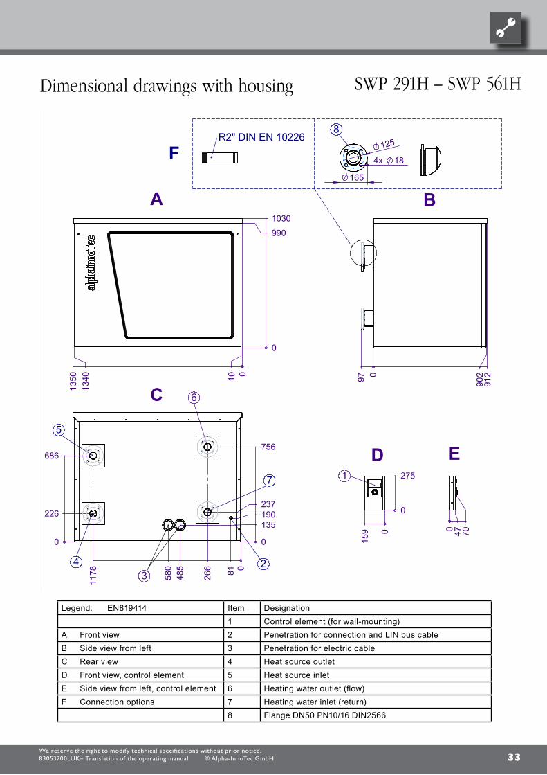
33
0
1030
990010
1340
1350
A
097 912
902
B
0
135
756
190
081266
485
580
1178
237
0
226
686
3
6C
2
7
4
5
0
275
0
159
D1
0 47 70E
165
4x 18
1258
R2" DIN EN 10226
Legende : DE819414
A VorderansichtB Seitenansicht von linksC RückansichtD Vorderansicht BedienteilE Seitenansicht von links BedienteilF Anschlussmöglichkeiten
F
Pos. Bezeichnung1 Bedienteil (für Wandmontage)2 Durchführung für Verbindungs- und LIN-Bus-Kabel3 Durchführung für Elektrokabel4 Wärmequelle Austritt5 Wärmequelle Eintritt 6 Heizwasser Austritt (Vorlauf)7 Heizwasser Eintritt (Rücklauf)8 Flansch DN50 PN10/16 DIN2566
87654321
www.alpha-innotec.deD - 95359 Kasendorf
Industriestraße 3Alpha-InnoTec GmbH
1
1
Ers. d. Ers. f.
A
B
C
D
E
F F
E
D
C
B
A
4321
BenennungMaßbildSWP-H Redesign AIT
819414 -Zust. Änderungstext
PEP 018/2011
Datum10.5.2012
DMVon
Blatt
von
Werkstoff Gewicht
Maßstab 1:20 1:15Det. Maßstab
Datum NameErstelltGepr.Norm.
10.5.2012 Kleuderlein10.5.2012 Markieton
toleranzAllgemein-
DIN ISO 2768 -c
Oberflächen
ArtikelNr.Alle Maße in mm. Toutes les mesures en mm. All measures in mm.Technische Änderungen vorbehalten. Sous réserve de modifications techniques. Subject to technical modifications.
Schu
tzverm
erk IS
O 16
016 b
each
ten
Legend: EN819414 Item Designation1 Control element (for wall-mounting)
A Front view 2 Penetration for connection and LIN bus cableB Side view from left 3 Penetration for electric cableC Rear view 4 Heat source outlet D Front view, control element 5 Heat source inlet E Side view from left, control element 6 Heating water outlet (flow)F Connection options 7 Heating water inlet (return)
8 Flange DN50 PN10/16 DIN2566
We reserve the right to modify technical specif ications without prior notice.83053700cUK– Translation of the operating manual © Alpha-InnoTec GmbH
Dimensional drawings with housing sWP 291H – sWP 561H

34
1030 >1
600
A1
2
max. 13m
>800
912
>900
>500 >500
1350
B
1
Legende : DE819408
A VorderansichtB Draufsicht1 Schraffierte Fläche Freiraum für Servicezwecke2 Bedienteil
87654321
www.alpha-innotec.deD - 95359 Kasendorf
Industriestraße 3Alpha-InnoTec GmbH
1
1
Ers. d. Ers. f.
A
B
C
D
E
F F
E
D
C
B
A
4321
BenennungAufstellungsplanSWP Redesign
819408 -Zust. Änderungstext
PEP 007/2011
Datum28.9.2011
REVon
Blatt
von
Werkstoff Gewicht
Maßstab 1:50 Det. Maßstab
Datum NameErstelltGepr.Norm.
15.9.2011 Eberlein
toleranzAllgemein-
DIN ISO 2768 -c
Oberflächen
ArtikelNr.Alle Maße in mm. Toutes les mesures en mm. All measures in mm.Technische Änderungen vorbehalten. Sous réserve de modifications techniques. Subject to technical modifications.
Schu
tzverm
erk IS
O 16
016 b
each
ten
Legend: EN819408
A Front viewB Plan view1 Hatched area = space for service purposes2 Control element
We reserve the right to modify technical specif ications without prior notice.83053700cUK– Translation of the operating manual © Alpha-InnoTec GmbH
sWP 371 – 691, sWP 291H - 561H installation plan

35
>160
010
30
A1
2
>800
912
>900
>2730>30
>500>500
B
1
Legende : DE819409
A VorderansichtB Draufsicht1 Schraffierte Fläche Freiraum für Servicezwecke2 Bedienteil
max.13m
87654321
www.alpha-innotec.deD - 95359 Kasendorf
Industriestraße 3Alpha-InnoTec GmbH
1
1
Ers. d. Ers. f.
A
B
C
D
E
F F
E
D
C
B
A
4321
BenennungAufstellungsplan
SWP Redesign Kaskadenaufstellung
819409 -Zust. Änderungstext
PEP 007/2011
Datum28.9.2011
REVon
Blatt
von
Werkstoff Gewicht
Maßstab 1:50 Det. Maßstab
Datum NameErstelltGepr.Norm.
15.9.2011 Eberlein
toleranzAllgemein-
DIN ISO 2768 -c
Oberflächen
ArtikelNr.Alle Maße in mm. Toutes les mesures en mm. All measures in mm.Technische Änderungen vorbehalten. Sous réserve de modifications techniques. Subject to technical modifications.
Schu
tzverm
erk IS
O 16
016 b
each
ten
Legend: EN819409
A Front viewB Plan view1 Hatched area = space for service purposes2 Control element
We reserve the right to modify technical specif ications without prior notice.83053700cUK– Translation of the operating manual © Alpha-InnoTec GmbH
installation plan sWP 371 – 691, sWP 291H - 561H

36
12
-F11
34
56
-F1
2
A1
A2
FP
1
EV
U
FP1
Sub-distribution unit intern
al installation
ASD
PE
X
TA
L1
Pum
p for mixing circuit 1
Leg
en
d:
MA
1/MIS
HU
P
Charge/discharge/cooling m
ixer 1 close
d
EV
U
X0-X
4
Hot w
ater gauge/therm
ostat
Heating circuit circulating pum
p
TBW
Accessories: R
emote control
TRL
VBO
PEX
ZW1
GND
Q0:L
1,L2,L3,PE
Controller board; A
ttention: I-max =
6A
/230VA
C
3
TB
1
External return sensor
GND
MOT
Hot w
ater circulating pum
p/switching valve
TR
L
ZUP
ZW
1
3~PE/400V/50Hz
Term
inal strips on controller board
Function
Q0
Term
inals in heat pum
p switchbox
External flo
w ra
te switch; bridge if no sw
itch is connecte
d.
N
Main
contactor; m
ains power 3~
PE
/400V/50H
z
M
RF
V
X10
Q0
BU
P
RFV
2
F11
L1
GND
Energy supplier contact; close
d on release; bridge if no blocking inte
rval
A5
TA
-X3
NM
IS
MZ1
GND
-X2
EVUC
ontrol signal of additional heat g
enerator 1
MO
T
ZIP
X10:L,N
,PE
N
TBW
N
X10
1~N/PE/230V/50Hz
TB1
Sensor m
ixing circuit 1
PE
ZU
P
4
SW
P
VB
O
A1
F12
A5
Cut out controller unit
A2
A1
connection
control unit
L
-X
LIN
Nam
e
External sensor
ZW
2/SS
T
ZW2/SST
TA
Single pole m
iniature circuit-breaker of compressor to IE
C 60947-2; Im
portant: Clockw
ise rotary field is absolutely essential!
L1
Auxiliary circulation pum
p
L2
No function
Control signal of add
itional heat generator 2 (alternative is general m
alfunction)HUP
PE
-X1
0
DF
S
PE
Brine pum
p
TB1
PE
PE
MA1
HU
P
Pow
er supply controller 230V ZU
P
Term
inal strip in sw
itchbox of heat pum
p; N/P
E distribu
tion for external 230V units
TB
W
UK
83
1175
N
Connection of external m
otor protection; bridge if no external m
otor protection is connected.
PE
FP
1
L1
DF
S
ZIP
Control e
lement
RFV
ZW
2
Pow
er supply compressor; 3x400V
; Importa
nt: Clockw
ise rotary field is absolutely necessary!
-X4
Term
inals
GND
MZ
1/MIS
VB
O
A2
MO
T
TRL
Charge/discharge/cooling m
ixer 1 open
3
2
-X0
LIN
ZW
1
Information
on fuses can be found in the technical data
GND
L3
BU
P
circulation pump
ZIP
X10
BUP
1
Term
inal diagram S
WP
generation 2011831175
Achim
Pfleg
er3
0.05.2
011
-P
EP
007/2011
12
34
56
78
910
1112
1314
1516
12
34
56
78
910
1112
1314
1516 1
/1
1
30.0
9.2
011
Achim
Pfleg
er
Blatt-N
r.
Zusta
ndÄ
nde
rung
Bea
rb.
Datu
mN
ame
Bl vo
n An
z
Datu
m
We reserve the right to modify technical specif ications without prior notice.83053700cUK– Translation of the operating manual © Alpha-InnoTec GmbH
terminal diagram sWP 371 – 691, sWP 291H - 561H

37
12
-Q0
/2.5
34
56P
E
-X1
0
12
-Q214
34
56
12
-Q1
/2.4
34
M3
T1
T2
T3
PE
-M1
VD
1
56
-E2
0
L3In
L3B
HS
o
HS
i
X1
X2
X3
X4
X5
X6
L3B
o
L3out
L2In
L2B
L2B
o
L2out
L1In
L1B
L1B
o
L1out
N-A
2
NC
-A1
32
13
21 L1
-Q11
LINS
A-1
/2.1LIN
SA
-2/2.1
LINS
A-3
/2.1
A1
A2
-Q2
L R
eg
/2.1
E20
/2.1
N/2.1
HS
o/2.1
HS
i/2.1
12
63
47
56
7
L3
L2
L1
L1,L2,L3,PE
; power supply, output, com
pressor; clockwise rotary field is absolutely nece
ssary!
Q0
M1
13
Q2
Main
s contactor, com
pressor
X10
Term
inal in sw
itch box heat pum
p 3~PE
/400
V/50H
z
Function
Sum
p heating for com
pressor 1
Bypass contactor, soft sta
rterQ
11
Leg
en
d:
PE
VD
1
2
Q1
contactor, com
pressor
UK
81
7379
VD
1
compressor
Starting current lim
it compressor
Operating m
aterials
3~P
E/400V
/50Hz
E20
-M1
SW
P 371; S
WP
451817379
Achim
Pfleg
er1
7.05.2
011
-P
EP
007/2011
12
34
56
78
910
1112
1314
1516
12
34
56
78
910
1112
1314
1516 1
/3
1
30.0
9.2
011
Achim
Pfleg
er
10X614 - 1
0X6
15;
Blatt-N
r.
Zusta
ndÄ
nde
rung
Bea
rb.
Datu
mN
ame
Bl vo
n An
z
Datu
m
We reserve the right to modify technical specif ications without prior notice.83053700cUK– Translation of the operating manual © Alpha-InnoTec GmbH
Circuit diagram 1/3 sWP 371, sWP 451
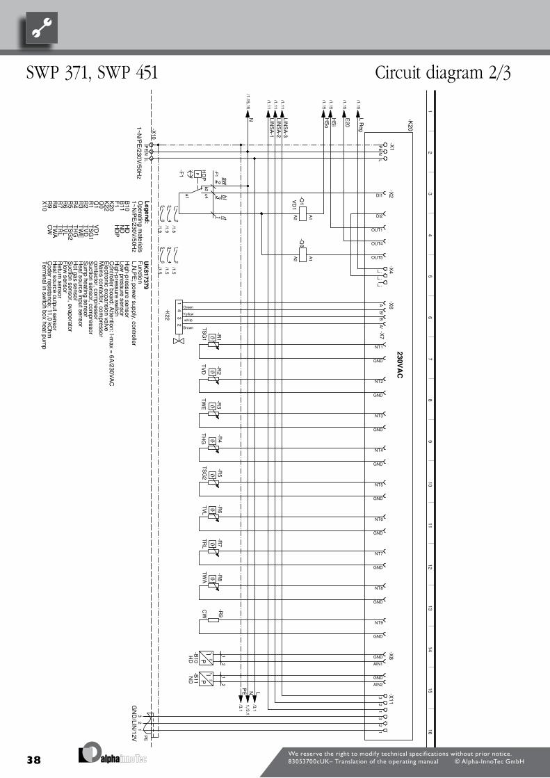
38
L R
eg/1.15
E20
/1.15
HS
i/1.15
HS
o/1.15
LIN
SA
-3/1.11
LIN
SA
-2/1.11
LIN
SA
-1/1.11
N/1.15
,15
PE
-X1PE
-X10
NN
LL
P+
-
b2c4a1
-F1
HD
P
DI1
-X2
DI2
A1
A2
-Q1VD
1
OUT1
OUT4
OUT5
A1
A2
-Q0
L..
-X4
L..
L..
A
-X6
B/
Green
Yellow
white
Brown
-K22 B
A/
ϑ
NT1
-X7
-R1
TS
G1
GND
ϑ
NT2
-R2
TV
D
GND
ϑ
NT3
-R3
TW
E
GND
ϑ
NT4
-R4
TH
G
GND
ϑ
NT5
-R5
TS
G2
GND
ϑ
NT6
-R6
TV
L
GND
ϑ
NT7
-R7
TR
L
GND
ϑ
NT8
-R8
TW
A
GND
NT9
-R9
CW
GND
GND
-X8
IP
12
-B10
HD
AIN1
GND
IP
12
-B11
ND
AIN2
L/3.1
N1,/3.1
PE
/3.1
3
-X1
121
32
32
1P
E
1
12
/1.53
4/1.5
56
/1.5
12
/1.83
4/1.9
56
/1.9
UK
81
7379
TW
E
Q0
2
TS
G1
R2
High-pressu
re switch
TR
L
TS
G2
R8
B10
HD
Controller board; A
ttention: I-max =
6A
/230VA
C
VD
1
3
contactor, com
pressor
Hot gas sensor
23
0V
AC
R1
Coder resista
nce; 11,0 kOhm
-F1
Q1
Sum
p heating sensor
GN
D/LIN
/12V
Leg
en
d:
R4
1~N
/PE
/230V/50H
z
K22
HD
P
R9
K20
F1
r t
High-pressu
re sensor
-K201~N
/PE
/230V/50H
z
TH
G
1
TV
L
sw
2
Heat source
input sensor
Suction sensor, com
pressor
1
TV
D
41
23
CW
TW
A
R5
Term
inal in sw
itch box heat pum
pX
10
Function
L,N,P
E; pow
er supply, controller
R3
Electro
nic expansion valve
ND
Heat source
output sensor
Low pressure sensor
Suction sensor, evaporator
R7
Main
s contactor, com
pressor
Operating m
aterials
blB
11
Flow
sensorR
eturn sensor
2
R6
1
SW
P 371; S
WP
451817379
Achim
Pfleg
er2
7.09.2
010
-P
EP
007/2011
12
34
56
78
910
1112
1314
1516
12
34
56
78
910
1112
1314
1516 2
/3
2
30.0
9.2
011
Achim
Pfleg
er
10X614 - 1
0X6
15;
Blatt-N
r.
Zusta
ndÄ
nde
rung
Bea
rb.
Datu
mN
ame
Bl vo
n An
z
Datu
m
We reserve the right to modify technical specif ications without prior notice.83053700cUK– Translation of the operating manual © Alpha-InnoTec GmbH
sWP 371, sWP 451 Circuit diagram 2/3

39
L/2.15
N/2.15
PE
/2.15
L-X
0N
PE
L-X
0L
L
MOT
-X2
.
ASD
EVU
K10
MO
TC
onnection of external motor prote
ction; bridge if no external motor protection is connected.
UK
81
7379
Controller board; A
ttention: I-max =
6A
/230VA
C
AS
DF
unction
EV
U
External flo
w ra
te switch; bridge if no sw
itch is connecte
d.
Leg
en
d:
-K10
MO
T
Operating m
aterials
AS
D
Energy supplier contact; close
d on release; bridge if no blocking inte
rvalE
VU
SW
P 371; S
WP
451817379
Achim
Pfleg
er2
3.05.2
011
-P
EP
007/2011
12
34
56
78
910
1112
1314
1516
12
34
56
78
910
1112
1314
1516 3
/3
3
30.0
9.2
011
Achim
Pfleg
er
10X614 - 1
0X6
15;
Blatt-N
r.
Zusta
ndÄ
nde
rung
Bea
rb.
Datu
mN
ame
Bl vo
n An
z
Datu
m
We reserve the right to modify technical specif ications without prior notice.83053700cUK– Translation of the operating manual © Alpha-InnoTec GmbH
Circuit diagram 3/3 sWP 371, sWP 451

40
12
-Q0
/2.5
34
56P
E
-X10
12
-Q215
34
56
12
-Q1
/2.4
34
M3
T1
T2
T3
PE
-M1
VD
1
56
T1
-230
V
T2
M1
-F1
.1 M2
L3In
L3B
HS
o
HS
i
X1
X2
X3
X4
X5
X6
L3B
o
L3out
L2In
L2B
L2B
o
L2out
L1In
L1B
L1B
o
L1out
N-A
2
NC
-A1
32
13
21 L1
-Q11
LINS
A-1
/2.1LIN
SA
-2/2.1
LINS
A-3
/2.1
L R
eg
/2.1N
/2.1
HD
P/2.1
MO
T/2.1
HS
o/2.1
HS
i/2.1
A1
A2
-Q2
12
53
46
56
6
1
Sum
p heating for com
pressor 1
Term
inal in sw
itch box heat pum
p
3
Function
3~P
E/400V
/50Hz
contactor, com
pressor
Q2
M1
Q0
VD
1
X10
E20
Main
s contactor, com
pressor
1
L1,L2,L3,PE
; power supply, output, com
pressor; clockwise rotary field is absolutely nece
ssary!
3
3~P
E/400V
/50Hz
Operating m
aterials
24
Leg
en
d:
PE
Com
pressor motor protection
L2
L3
F1.1
L1
VD
1
Q1
compressor
-M1
Starting current lim
it compressor
Q11
UK
81
7380
2
Bypass contactor, soft sta
rter
SW
P 581 - 691; S
WP
291H - 561H
817380
Achim
Pfleg
er1
7.05.2
011
-P
EP
007/2011
12
34
56
78
910
1112
1314
1516
12
34
56
78
910
1112
1314
1516 1
/3
1
30.0
9.2
011
10X
618; 10X61
9;
Achim
Pfleg
er
10X616; 10
X61
7;B
latt-Nr.
Zusta
ndÄ
nde
rung
Bea
rb.
Datu
mN
ame
Bl vo
n An
z
Datu
m
We reserve the right to modify technical specif ications without prior notice.83053700cUK– Translation of the operating manual © Alpha-InnoTec GmbH
sWP 581, sWP 691, sWP 561H Circuit diagram 1/3

41
L R
eg/1.15
HS
i/1.15
HS
o/1.15
LIN
SA
-3/1.13
LIN
SA
-2/1.13
LIN
SA
-1/1.13
MO
T/1.15
HD
P/1.15
N/1.15
,15
PE
-X1PE
-X10
NN
LL
P+
-
b2c4a1
-F1
HD
P
DI1
-X2
DI2
1314
-Q05
A1
A2
-Q1VD
1
1
-X1
0OUT1
OUT5
A1
A2
-Q0
L..
-X4
L..
L..
A
-X6
B/
Green
Yellow
white
Brown
-K22
BA
/
ϑ
NT1
-X7
-R1
TS
G1
GND
ϑ
NT3
-R3
TW
E
GND
ϑ
NT4
-R4
TH
G
GND
ϑ
NT5
-R5
TS
G2
GND
ϑ
NT6
-R6
TV
L
GND
ϑ
NT7
-R7
TR
L
GND
ϑ
NT8
-R8
TW
A
GND
NT9
-R9
CW
GND
GND
-X8I
P
12
-B10
HD
AIN1
GND
IP
12
-B11
ND
AIN2
L/3.1
N1,/3.1
PE
/3.1
3
-X11
21
32
32
1P
E
1
12
/1.43
4/1.4
56
/1.413
144
12
/1.73
4/1.8
56
/1.8
43
21
1
TW
A
TV
L
Term
inal in sw
itch box heat pum
p
-K20
2
X10
2
K20
Hot gas sensor
1
Function
TH
G
HD
TR
L
contactor, com
pressor
Main
s contactor, com
pressor
GN
D/LIN
/12VH
igh-pressure sensor
R6
TS
G2
R4
Q1
F1
1~N/P
E/230V
/50Hz
High-pressu
re switch
R2
Electro
nic expansion valve
2
1~N
/PE
/230V/50H
z
VD
1
3
TS
G1 2
30V
AC
rt
-F1
Suction sensor, evaporator
Controller board; A
ttention: I-max =
6A
/230VA
C
Suction sensor, com
pressor
B10
Leg
en
d:
1
Low pressure sensor
R9
CW
Coder resista
nce; S58-69K
W 11,5kO
hm / S
29-56KW
12,1kO
hm
TV
DS
ump heating sensor
TW
E
Flow
sensorR
5
K22
Return sensor
B11
R7
R1
HD
P
Q0
Operating m
aterials
R3
Heat source
output sensorR
8
sw
UK
81
7380
ND
L,N,P
E; pow
er supply, controller
Heat source
input sensor
bl
SW
P 581 - 691; S
WP
291H - 561H
817380
Achim
Pfleg
er2
7.09.2
010
-P
EP
007/2011
12
34
56
78
910
1112
1314
1516
12
34
56
78
910
1112
1314
1516 2
/3
2
30.0
9.2
011
10X
618; 10X61
9;
Achim
Pfleg
er
10X616; 10
X61
7;B
latt-Nr.
Zusta
ndÄ
nde
rung
Bea
rb.
Datu
mN
ame
Bl vo
n An
z
Datu
m
We reserve the right to modify technical specif ications without prior notice.83053700cUK– Translation of the operating manual © Alpha-InnoTec GmbH
Circuit diagram 2/3 sWP 581, sWP 691, sWP 561H
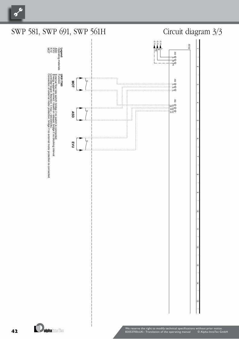
42
L/2.15
N/2.15
PE
/2.15
L-X
0N
PE
L-X
0L
L
MOT
-X2
.
ASD
EVU
-K10
MO
T
External flo
w ra
te switch; bridge if no sw
itch is connecte
d.
Leg
en
d:
Energy supplier contact; close
d on release; bridge if no blocking inte
rvalE
VU
Operating m
aterials
AS
D
K10
Controller board; A
ttention: I-max =
6A
/230VA
CM
OT
UK
81
7380
EV
U
Connection of external m
otor protection; bridge if no external m
otor protection is connected.
AS
DF
unction
SW
P 581 - 691; S
WP
291H - 561H
817380
Achim
Pfleg
er2
3.05.2
011
-P
EP
007/2011
12
34
56
78
910
1112
1314
1516
12
34
56
78
910
1112
1314
1516 3
/3
3
30.0
9.2
011
10X
618; 10X61
9;
Achim
Pfleg
er
10X616; 10
X61
7;B
latt-Nr.
Zusta
ndÄ
nde
rung
Bea
rb.
Datu
mN
ame
Bl vo
n An
z
Datu
m
We reserve the right to modify technical specif ications without prior notice.83053700cUK– Translation of the operating manual © Alpha-InnoTec GmbH
sWP 581, sWP 691, sWP 561H Circuit diagram 3/3

43
12
-Q0
/2.5
34
56P
E
-X1
0
12
-Q214
34
56
12
-Q1
/2.4
34
M3
T1
T2
T3
PE
-M1
VD
1
56
ϑ-F2
L3In
L3B
HS
o
HS
i
X1
X2
X3
X4
X5
X6
L3B
o
L3out
L2In
L2B
L2B
o
L2out
L1In
L1B
L1B
o
L1out
N-A
2
NC
-A1
32
13
21 L1
-Q11
LINS
A-1
/2.1LIN
SA
-2/2.1
LINS
A-3
/2.1
A1
A2
-Q2
L R
eg
/2.1
N/2.1
HS
o/2.1
HS
i/2.1
MO
T/2.1
L-Steu
/2.1
12
63
47
56
7
1
Com
pressor motor protection
Q0
F2
L3
L2
L1
L1,L2,L3,PE
; power supply, output, com
pressor; clockwise rotary field is absolutely nece
ssary!
M1
1
Q2
Main
s contactor, com
pressor
X10
Term
inal in sw
itch box heat pum
p
3
3~PE
/400
V/50H
z
Starting current lim
it compressor
Function
VD
1
Leg
en
d:
compressor
Bypass contactor, soft sta
rter
22
PE
-M1
contactor, com
pressor
UK
81
7385a
Q11
Q1
VD
1
Operating m
aterials
3~P
E/400V
/50Hz
SW
P 291H
817385
Achim
Pfleg
er0
8.02.2
012
aÄ
M 037/2013
12
34
56
78
910
1112
1314
1516
12
34
56
78
910
1112
1314
1516 1
/3
1
03.0
6.2
013
PE
P 007/2011
Achim
Pfleg
er
10X618;
Blatt-N
r.
Zusta
ndÄ
nde
rung
Bea
rb.
Datu
mN
ame
Bl vo
n An
z
Datu
m
We reserve the right to modify technical specif ications without prior notice.83053700cUK– Translation of the operating manual © Alpha-InnoTec GmbH
Circuit diagram 1/3 sWP 291H

44
L R
eg/1.15
MO
T/1.15
L-S
teu/1.15
HS
i/1.15
HS
o/1.15
LIN
SA
-3/1.11
LIN
SA
-2/1.11
LIN
SA
-1/1.11
N/1.15
,15
PE
-X1PE
-X10
NN
LL
P+
-
b2c4a1
-F1
HD
P
DI1
-X2
DI2A
1
A2
-Q1VD
1OUT1
OUT5
A1
A2
-Q0
L..
-X4
L..
L..
B/
-X6
A
Green
Yellow
white
Brown
-K22 A
/B
ϑ
NT1
-X7
-R1
TS
G1
GND
ϑ
NT3
-R3
TW
E
GND
ϑ
NT4
-R4
TH
G
GND
ϑ
NT5
-R5
TS
G2
GND
ϑ
NT6
-R6
TV
L
GND
ϑ
NT7
-R7
TR
L
GND
ϑ
NT8
-R8
TW
A
GND
NT9
-R9
CW
GND
GND
-X8
IP
12
-B10
HD
AIN1
GND
IP
12
-B11
ND
AIN2
L/3.1
N1,/3.1
PE
/3.1
3
-X1
121
32
32
1P
E
1
12
/1.53
4/1.5
56
/1.5
12
/1.83
4/1.9
56
/1.9
23
41
CW
Term
inal in sw
itch box heat pum
pX
10
TW
A
R5
1
TV
L
Low pressure sensor
TH
G
21
sw
Heat source
input sensor
Suction sensor, com
pressor
blB
11
Main
s contactor, com
pressor
Operating m
aterials
Flow
sensorR
6
1
Return sensor
2
R3
Electro
nic expansion valve
Function
L,N,P
E; pow
er supply, controller
ND
Suction sensor, evaporator
R7
Heat source
output sensor
HD
Controller board; A
ttention: I-max =
6A
/230VA
C
R8
B10
VD
1
Hot gas sensor
23
0V
AC
3
contactor, com
pressor
Q0
2
UK
81
7385a
TW
ET
SG
1
TR
L
TS
G2
High-pressu
re switch
R9
K20
K22
HD
PF
1
-K201~N
/PE
/230V/50H
z
rt
High-pressu
re sensor
-F1
Q1
R1
Coder resista
nce; 18,7 kOhm
R4
1~N
/PE
/230V/50H
zG
ND
/LIN/12V
Leg
en
d:
SW
P 291H
817385
Achim
Pfleg
er2
7.09.2
010
aÄ
M 037/2013
12
34
56
78
910
1112
1314
1516
12
34
56
78
910
1112
1314
1516 2
/3
2
03.0
6.2
013
PE
P 007/2011
Achim
Pfleg
er
10X618;
Blatt-N
r.
Zusta
ndÄ
nde
rung
Bea
rb.
Datu
mN
ame
Bl vo
n An
z
Datu
m
We reserve the right to modify technical specif ications without prior notice.83053700cUK– Translation of the operating manual © Alpha-InnoTec GmbH
sWP 291H Circuit diagram 2/3

45
L/2.15
N/2.15
PE
/2.15
L-X
0N
PE
L-X
0L
L
MOT
-X2
.
ASD
EVU
-K10
MO
T
External flo
w ra
te switch; bridge if no sw
itch is connecte
d.
Leg
en
d:
Energy supplier contact; close
d on release; bridge if no blocking inte
rvalE
VU
Operating m
aterials
AS
D
Connection of external m
otor protection; bridge if no external m
otor protection is connected.
UK
81
7385a
K10
MO
T
Function
EV
U
Controller board; A
ttention: I-max =
6A
/230VA
C
AS
D
SW
P 291H
817385
Achim
Pfleg
er2
3.05.2
011
aÄ
M 037/2013
12
34
56
78
910
1112
1314
1516
12
34
56
78
910
1112
1314
1516 3
/3
3
03.0
6.2
013
PE
P 007/2011
-A
chim P
fleger
10X618;
Blatt-N
r.
Zusta
ndÄ
nde
rung
Bea
rb.
Datu
mN
ame
Bl vo
n An
z
Datu
m
We reserve the right to modify technical specif ications without prior notice.83053700cUK– Translation of the operating manual © Alpha-InnoTec GmbH
Circuit diagram 3/3 sWP 291H

46
The undersignedconfirms that the following designated device(s) as designed and marketed by us ful-fill the standardized Ec directives, the Ec safety standards and the product-specific Ec standards. In the event of modification of the device(s) without our approval, this declaration shall become invalid.
designationofthedeViCe(s)
Heat pump
unit model number unit model numberSWP 371 * 100 614SWP 451 * 100 615SWP 581 * 100 616SWP 691 * 100 617SWP 291H * 100 618SWP 561H * 100 621
eC Directives standardized en2006/42/EG EN 378 EN 3492006/95/EG EN 60529 EN 60335-1/-2-402004/108/EG EN ISO 12100-1/2 EN 55014-1/-2* 97/23/EG EN ISO 13857 EN 61000-3-2/-3-3
* Pressure equipment componentCategory IIModule A1
Designated position:TÜv-SÜd Industrie Service GmbH (Nr.:0036)
Company: Place, date:
Signature:
Jesper Stannow Technical Director
We reserve the right to modify technical specif ications without prior notice.83053700cUK– Translation of the operating manual © Alpha-InnoTec GmbH
eC declaration of conformity

47We reserve the right to modify technical specif ications without prior notice.83053700cUK– Translation of the operating manual © Alpha-InnoTec GmbH

48

49We reserve the right to modify technical specif ications without prior notice.83053700cUK– Translation of the operating manual © Alpha-InnoTec GmbH
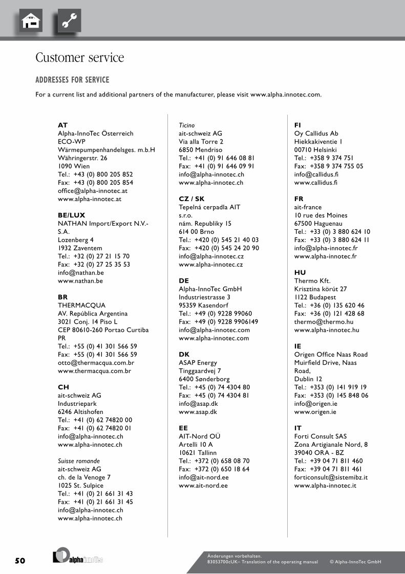
50
at Alpha-InnoTec Österreich Eco-Wp Wärmepumpenhandelsges. m.b.H Währingerstr. 26 1090 Wien Tel.: +43 (0) 800 205 852fax: +43 (0) 800 205 [email protected] www.alpha-innotec.at Be/LuX NATHAN Import/Export N.v.-S.A. lozenberg 4 1932 Zaventem Tel.: +32 (0) 27 21 15 70fax: +32 (0) 27 25 35 [email protected] www.nathan.be Br THERmAcqUA Av. República Argentina 3021 conj. 14 piso l cEp 80610-260 portao curtiba pR Tel.: +55 (0) 41 301 566 59fax: +55 (0) 41 301 566 [email protected] www.thermacqua.com.br CH ait-schweiz AG Industriepark 6246 Altishofen Tel.: +41 (0) 62 74820 00fax: +41 (0) 62 74820 [email protected] www.alpha-innotec.ch Suisse romande ait-schweiz AG ch. de la venoge 7 1025 St. Sulpice Tel.: +41 (0) 21 661 31 43fax: +41 (0) 21 661 31 [email protected] www.alpha-innotec.ch
Ticino ait-schweiz AG via alla Torre 2 6850 mendriso Tel.: +41 (0) 91 646 08 81fax: +41 (0) 91 646 09 [email protected] www.alpha-innotec.ch CZ / sK Tepelná cerpadla AIT s.r.o. nám. Republiky 15 614 00 brno Tel.: +420 (0) 545 21 40 03fax: +420 (0) 545 24 20 [email protected] www.alpha-innotec.cz De Alpha-InnoTec GmbH Industriestrasse 3 95359 Kasendorf Tel.: +49 (0) 9228 99060fax: +49 (0) 9228 [email protected] www.alpha-innotec.com DK ASAp Energy Tinggaardvej 7 6400 Sønderborg Tel.: +45 (0) 74 4304 80fax: +45 (0) 74 4304 [email protected] www.asap.dk ee AIT-Nord oÜ Artelli 10 A 10621 Tallinn Tel.: +372 (0) 658 08 70fax: +372 (0) 650 18 [email protected] www.ait-nord.ee
FI oy callidus Ab Hiekkakiventie 1 00710 Helsinki Tel.: +358 9 374 751fax: +358 9 374 755 [email protected] www.callidus.fi Fr ait-france 10 rue des moines 67500 Haguenau Tel.: +33 (0) 3 880 624 10fax: +33 (0) 3 880 624 [email protected] www.alpha-innotec.fr Hu Thermo Kft. Krisztina körút 27 1122 budapest Tel.: +36 (0) 135 620 46fax: +36 (0) 121 428 [email protected] www.alpha-innotec.hu Ie origen office Naas Road muirfield drive, Naas Road, dublin 12 Tel.: +353 (0) 141 919 19fax: +353 (0) 145 848 [email protected] www.origen.ie It forti consult SAS Zona Artigianale Nord, 8 39040 oRA - bZ Tel.: +39 04 71 811 460fax: +39 04 71 811 [email protected] www.alpha-innotec.it
Änderungen vorbehalten.83053700cUK– Translation of the operating manual © Alpha-InnoTec GmbH
Customer service
addressesforserViCe
for a current list and additional partners of the manufacturer, please visit www.alpha.innotec.com.

51
Lt/Lv UAb TENKo baltic basanaviciaus g. 45 03109 vilnius Tel.: +370 526 435 82fax: +370 526 435 [email protected] www.tenko.lt nL NATHAN Import/Export b.v. Impact 73 6921 RZ duiven Tel.: +31 (0) 26 445 98 45fax: +31 (0) 26 445 93 [email protected] www.nathan.nl no Alpha-InnoTec Norge AS Gamle forusveien 51b 4033 Stavanger Tel.: +47 (0) 51 6605 95fax: +47 (0) 51 6605 [email protected] www.alpha-innotec.no pL Hydro-Tech ul. Zakładowa 4d 62-510 Konin Tel.: +48 (0) 63 245 34 79fax: +48 (0) 63 242 37 [email protected] www.hydro-tech.pl pt GudEnergy Energias Renováveis, lda. Av. o Século, 21 r/c d.to 2135-231 Samora correia Tel.: +351 (0) 263 655 439fax: +351 (0) 263 655 [email protected] www.gudenergy.pt
se bjärneroth Teknik Evas väg 5 280 64 Glimåkra Tel.: +46 (0) 708 420 544fax: +46 (0) 444 222 [email protected] www.btait.se sI EkoEnergija d.o.o. mače 6 4205 preddvor Tel.: +386 (0) 42 555 780fax: +386 (0) 42 555 [email protected] www.ekoenergija.eu uK Econic ltd marsham Norwich Road Norfolk NR 10 5pq Tel.: +44 (0) 16 032 770 40fax: +44 (0) 87 091 203 [email protected] www.econicres.com 20130113
Änderungen vorbehalten.83053700cUK– Translation of the operating manual © Alpha-InnoTec GmbH

Recommended