BD Deck 1: A New Precast, Pre-stressed
Concrete Panel Bridge Deck System
SAMA AHMED
NUSRAT JAHAN
AVISHEK CHOWDHURY
DEPARTMENT OF CIVIL ENGINEERING
AHSANULLAH UNIVERSITY OF SCIENCE AND TECHNOLOGY
MAY, 2017
BD Deck 1: A New Precast, Pre-stressed Concrete
Panel Bridge Deck System
THIS THESIS PAPER IS
Submitted By: Student ID
SAMA AHMED 13.01.03.013
NUSRAT JAHAN 13.01.03.044
AVISHEK CHOWDHURY 13.01.03.056
In partial fulfillment of requirements for the degree of
Bachelor of Science in Civil Engineering
Under the Supervision of
Dr. ENAMUR RAHIM LATIFEE
Associate Professor
Department of Civil Engineering
AHSANULLAH UNIVERSITY OF SCIENCE AND TECHNOLOGY
MAY, 2017

DEDICATION
TO OUR
PARENTS, FAMILY AND TEACHERS

APPROVED AS TO STYLE AND CONTENT
BY
__________________________________
Dr. ENAMUR RAHIM LATIFEE
Associate Professor
Department of Civil Engineering
AHSANULLAH UNIVERSITY OF SCIENCE AND TECHNOLOGY
141-142 LOVE ROAD, TEJGAON INDUSTRIAL AREA, DHAKA-1208
MAY, 2017

Page i
DECLARATION
We hereby declare that the work performed in this thesis for the
achievement of the degree of Bachelor of Science in Civil Engineering is
“BD Deck 1: A New Precast, Pre-stressed Concrete Deck Panel”. The
whole work is carried out by authors under the guidance and strict
supervision of Dr. Enamur Rahim Latifee, Associate Professor of the
Department of Civil Engineering at Ahsanullah University of Science
and Technology (AUST), Dhaka, Bangladesh.
It is also being declared that the work performed in this thesis has not
been submitted and will not be submitted, either in part or in full for the
award of any other degree in this institute or any other institute or
university.
………………………………….
Sama Ahmed
ID: 13.01.03.013
…………………………………
Nusrat Jahan
ID: 13.01.03.044
………………………………….
Avishek Chowdhury
ID: 13.01.03.056

Page ii
ACKNOWLEDGEMENT
First and foremost, we would like to thank the Almighty for blessing us
with the opportunity to conduct such an important academic research to
aid in the progress of mankind.
From the bottom of our hearts, we pay the utmost respect to our thesis
supervisor and mentor, Dr. Enamur Rahim Latifee, Associate
Professor, Honorable faculty member, Department of Civil Engineering,
Ahsanulllah University of Science and Technology. Without his
assistance and dedicated involvement in every step of the work, this
paper would have never been accomplished. We would like to thank you
very much for your constant support and guidance during the entirety of
our thesis work.
Our gratitude also extends to our parents and family for their
unconditional trust, unwavering support and endless patience throughout
our lives.
Last but not least, a heartfelt thank you and utmost respect to all our
teachers, friends, seniors as well as juniors- who have all taught us how
to be successful academics and worthy individuals, during this beautiful
journey of four years.

Page iii
ABSTRACT
Strong communication is one of the key factors for development. Bridges are one of the major
components of a communication network. More so for Bangladesh since there are around 700
rivers here. However, there are insufficient bridges in the country for connectivity which is
hampering the economic growth. Also, the existing bridge types require long construction
periods of 2 to 3 years and have service life of only 60 years. In Bangladesh, reinforced concrete
(RC) girder bridges are used for spans less than 24m, pre-stressed concrete (PC) girder bridges
for 24m-48m spans, and PC box girders for spans greater than 48m. RC and PC girder bridge
decks are cast-in-place (CIP), which have an increased cost in terms of construction,
maintenance etc. Box girders are heavy and hence require high-capacity trucks and cranes for
transportation and member erection. In this paper, the concept of a new bridge deck type has
been presented, named “BD-Deck 1”. This concept is unique in its design. It is a segmental
bridge deck type that consists of full-depth precast, pre-stressed individual concrete panels
(PCP). This bridge deck system will use the existing designs of RC and PC girders as supporting
girders, but will replace the CIP bridge deck with PCP full-depth panels. The proposed bridge
type will be much more cost-effective, rapid in construction and have a longer service life with
minimal maintenance. The panels will be re-usable if needed for new bridges or rehabilitation of
old bridges. Preliminary estimation shows cost savings of around 4.31% in concrete material
cost, 83.59% in reinforcement cost, 54.02% in labor cost and 60.85% in transportation cost in
comparison to the CIP deck bridges constructed in Bangladesh. Moreover, if we consider
transportation and maintenance, this proposed deck system will be much more economical. It
will shorten the overall construction period since these are all precast panels; they need only be
transported to the job site. The service life of this deck type will be 100 years, which is much
higher than that of CIP systems of 60 years. Some types of PCP panels were first introduced in
the USA in the early 1960s. In Bangladesh, pre-stressed technology was first introduced in 1977-
1978 over the Boral River for PC girders. Since these panels are significantly more lightweight
and smaller compared to box girders, the same carrier truck can carry a lot more panels for
transportation during construction and are easier to place at the job site. Construction costs are
reduced as there need not be trucks and machinery required for CIP decks. These panels will
expedite deck bridge construction and create a more durable and sustainable system. The design
can be implemented on a few trial bridges and if successful, the panels can be mass-produced for
multiple bridge constructions, thereby reducing the production cost even more. The design
conforms to all local and international standard specifications.

Page iv
Table of Contents
Declaration………………………………………………………………………………..i
Acknowledgement……………………………………………………………………….ii
Abstract……………………………………………………………………………….....iii
Table of Contents………………………………………………………………………..iv
List of Figures…………………………………………………………………………..vii
List of Tables……………………………………………………………………………..x
List of Symbol and Abbreviation……………………………………………………....xi
Chapter- 01 (INTRODUCTION) .......................................................................................... 1
1.1 General .................................................................................................................................. 3
1.2 Bridges in Bangladesh ........................................................................................................... 3
1.3 Problem Statement ................................................................................................................ 4
1.4 Purposes behind implementation of a new bridge deck system in Bangladesh .................... 5
1.5 Benefits of this System .......................................................................................................... 8
1.6 Design Considerations........................................................................................................... 9
1.7 Choice of Design Code and Limitations ............................................................................. 10
1.8 Objective & Scope .............................................................................................................. 11
Chapter- 02(LITERATURE REVIEW) ......................................................................... 12
2.1 What is a BRIDGE? ............................................................................................................ 13
2.2 Early History of Bridges ..................................................................................................... 14
2.3 Overview of Bridges in Bangladesh.................................................................................... 16
2.3.1 CULVERTS.................................................................................................................. 17
2.3.2 Reinforced Cement Concrete (RCC) Bridges .............................................................. 19
2.3.3 Girder Bridges .............................................................................................................. 20
2.3.4 Reinforced Cement Concrete (RCC) Girder Bridges ................................................... 20
2.3.5 Pre-stressed Concrete (PC) Girder Bridges .................................................................. 21
2.3.6 Arch Bridges ................................................................................................................. 23

Page v
2.3.7 Truss Bridges ................................................................................................................ 25
2.3.8 Bailey Bridges .............................................................................................................. 28
2.3.9 Steel/ Concrete Composite Bridges .............................................................................. 31
2.3.10 Pre-Stressed Concrete Box Girder Bridges ................................................................ 32
2.4 Early History of PCP Bridge Deck Panel............................................................................ 33
2.5 Different PCP bridge deck systems ..................................................................................... 39
2.6 IMPORTANT TERMS ....................................................................................................... 40
2.6.1 High Performance Concrete ......................................................................................... 40
2.6.2 High Strength Steel ....................................................................................................... 40
2.6.3 Pre-tensioning ............................................................................................................... 41
2.6.4 Post-tensioning ............................................................................................................. 41
2.7 What is Concrete? ............................................................................................................... 42
2.7.1 What is Precast Concrete? ............................................................................................ 42
2.7.2 What is Cast-in-Place Concrete? .................................................................................. 44
2.8 Pre-stressed Concrete .......................................................................................................... 47
2.8.1 Advantages of Pre-stressed Concrete ........................................................................... 49
2.8.2 Disadvantages of Pre-stressed Concrete ....................................................................... 49
2.9 Pre-tensioning...................................................................................................................... 49
2.9.1 Advantages of Pre-tensioning ....................................................................................... 50
2.9.2 Disadvantages of Pre-tensioning .................................................................................. 50
2.10 Post-tensioning .................................................................................................................. 51
2.10.1 Advantages of Post-tensioning ................................................................................... 51
2.10.2 Disadvantages of Post-tensioning ............................................................................... 52
2.11 Full Depth Bridge Deck Panel .......................................................................................... 52
2.12 Partial Depth Bridge Deck Panels ..................................................................................... 53
2.13 Ribbed Slab ....................................................................................................................... 54
2.13.1 Background of Ribbed Slab ........................................................................................ 54
2.13.2 Purpose and Scope of Ribbed Slab ............................................................................. 55
2.14 Necessity of Shrinkage Reinforcement ............................................................................. 56
2.15 CODE Requirements ......................................................................................................... 56
2.15.1 Placement of Reinforcement ...................................................................................... 56

Page vi
Chapter- 03 (DESIGN OF BD DECK 1) ................................................................ 58
3.1 Specifications of Deck Girder Bridges in Bangladesh ........................................................ 59
3.2 DESIGN CONCEPTION .................................................................................................... 61
3.3 Design Calculation (For Exterior and Interior Deck Panel) ................................................ 62
3.3.1 Design of Curb.............................................................................................................. 63
3.3.2 Design of Railing .......................................................................................................... 65
3.3.3 Design of Rail Post ....................................................................................................... 67
3.4 BD DECK 1 DETAILS ....................................................................................................... 69
3.5 Construction process of Deck Panels .................................................................................. 71
3.5.1 Fabrication, Transportation, Handling and placement ................................................. 72
3.5.2 Pre-fabrication of Precast pre-stressed Deck panels ..................................................... 72
3.5.3 Transportation ............................................................................................................... 74
3.5.4 Handling ....................................................................................................................... 75
3.5.5 Precast Panel Placement ............................................................................................... 76
3.6 Steps of Deck Placement ..................................................................................................... 77
3.7 Joint Construction ............................................................................................................... 81
Chapter- 04 (ECONOMIC ANALYSIS) ................................................................ 82
4.1 Area Reduction .................................................................................................................... 83
4.2 Volume Reduction............................................................................................................... 83
4.3 Cost Details ......................................................................................................................... 84
4.3.1 RCC Deck Slab (For 21m span) ................................................................................... 84
4.3.2 BD deck 1 ..................................................................................................................... 90
4.4 Cost Comparison ................................................................................................................. 95
4.5 Comparison of Costs between RCC Deck Slab & BD Deck 1 per km ............................... 99
4.5.1BD Deck 1 ..................................................................................................................... 99
4.5.2 RCC DECK SLAB ..................................................................................................... 101
Chapter- 05 (CONCLUSION & RECOMMENDATION) .......................... 105
5.1 CONCLUSION ................................................................................................................. 106
5.2 RECOMMENDATION .................................................................................................... 107
BIBLIOGRAPHY………………………………………………………………………………108

Page vii
List of Figures
Figure 1.1: A Woodblock Ptolemaic Map, “Decima Asiae Tabula”, ‘Geographie Opus
Novissima’ (Strasbourg: J. Schott, 1513) ....................................................................................... 6
Figure 2.1: Cable Stayed Bridge, Shah Amanat, Chittagong ....................................................... 13
Figure 2.2: An Ancient Roman Arch Bridge ................................................................................ 14
Figure 2.3: Box Culvert ................................................................................................................ 18
Figure 2.4: Slab Culvert ................................................................................................................ 19
Figure 2.5: Reinforced Cement Concrete (RCC) Girder, Sangu Bridge, Bandarban ................... 20
Figure 2.6: Reinforced Cement Concrete (RCC) Bridge, Dhaleswari River Bridge, Munshiganj
....................................................................................................................................................... 21
Figure 2.7: Tensioning Process ..................................................................................................... 22
Figure 2.8: Pre-stressed Concrete (PC) Girder Bridge, Mohipur-Alipur, Patuakhali ................... 23
Figure 2.9: Arch Masonry ............................................................................................................. 24
Figure 2.10: Arch Masonry, Mir Kadim Bridge, Munshiganj ...................................................... 25
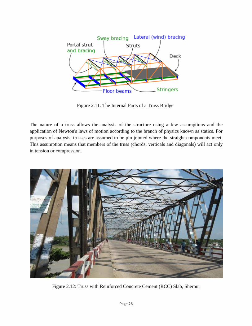
Figure 2.11: The Internal Parts of a Truss Bridge ........................................................................ 26
Figure 2.12: Truss with Reinforced Concrete Cement (RCC) Slab, Sherpur ……………………26
Figure 2.13: Truss with Timber Decks, Shah Amanat Bridge, Chittagong .................................. 27
Figure 2.14: Truss with Steel Deck, Boalia Bazar, Nalchiti, Barisal............................................ 27
Figure 2.15: Bailey Bridge with Steel Deck, Kalurghat Bridge, Chittagong ............................... 30
Figure 2.16: Bailey Bridge with Timber Deck, Koikhongjhiri, Bandarban ................................. 30
Figure 2.17: Steel Beam & Reinforced Cement Concrete (RCC) Slab, Isapur Bridge, Purbachal
....................................................................................................................................................... 32
Figure 2.18: Pre-stressed Concrete (PC) Box Girder, Bhairab Bridge ......................................... 33
Figure 2.19: Typical Transverse Section of a PCP-PD Bridge Deck System .............................. 39
Figure 2.20: Precast Concrete ....................................................................................................... 43
Figure 2.21: Cast-in-place Concrete ............................................................................................. 44
Figure 2.22: Pre-stressed Concrete ............................................................................................... 48
Figure 2.23: Pre-tensioning ........................................................................................................... 50
Figure 2.24: Post-tensioning ......................................................................................................... 51
Figure 2.25: Full Depth Bridge Deck Panel.................................................................................. 53
Page viii
Figure 2.26: Partial Depth Bridge Deck Panel .............................................................................. 54
Figure 2.27: Cross Section of the Ribbed Slab ............................................................................. 55
Figure 3.1: Reinforcement Details of a Typical Bridge Deck of a Span of 27m (Roads &
Highways Department, Bangladesh, 2016)……………………………………………………...59
Figure 3.2: Reinforcement Details of a Typical Bridge Deck of a Span of 21m ( Roads &
Highways Department, Bangladesh, 2016)………………………...……………………………60
Figure 3.3: Curb………………………………………………………………………………….63
Figure 3.4: Railing…………………………………………………...…………………………..65
Figure 3.5: Rail Post……………………………………………………………………………..67
Figure 3.6: Typical Cross Section of BD Deck 1…………………………………..……………70
Figure 3.7: Contraction Joints with Dowel Bar………………………………...…………..……70
Figure 3.8: Section A-A of Figure 3.7 ........................................... Error! Bookmark not defined.
Figure 3.9: BD Deck 1……………………...……………………………………………………71
Figure 3.10: Pre-fabrication of Deck Panels in Plants…………………………………………...72
Figure 3.11: Typical Formwork for Mass Production of Deck Panels………………………..…73
Figure 3.12: Transportation of Deck Panels……………………………………………………..75
Figure 3.13: Placement of Deck Panel………………………………...…………………………76
Figure 3.14: Lifting & Placement of a Panel on Supporting Girders………………………...….77
Figure 3.15: Placement of Subsequent Panels…………………………...………………………78
Figure 3.16: Shear Pockets between Panels Filled with Grout…………………………………..79
Figure 3.17: Construction of Deck Completed………………..…………………………………80
Figure 3.18: Cross Section View of Male-Female Panel Joint……………………...…………...81
Page ix
Figure 4.1: Typical deck Slab Detailing of 21m Span (Drawing from Roads & Highway
Department)…………………………...…………………………………………………………85
Figure 4.2: Comparison of Concrete material Cost…………………………...…………………95
Figure 4.3: Comparison of Reinforcement Cost…………………………………………………96
Figure 4.4: Comparison of Labor Cost……………..……………………………………………97
Figure 4.5: Comparison of Transportation Cost…………………………………………………97
Figure 4.6: Summary & Comparison of Costs between RCC Deck Slab & BD Deck 1………..98
Figure 4.7: Comparison of Costs between RCC Deck Slab & BD Deck 1 (per km)………..…104
Page x
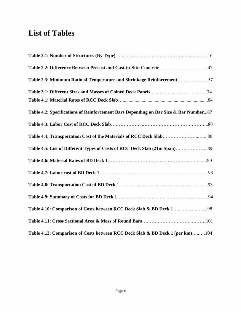
List of Tables
Table 2.1: Number of Structures (By Type)…………………………………………………..16
Table 2.2: Difference Between Precast and Cast-in-Situ Concrete…………...……………..47
Table 2.3: Minimum Ratio of Temperature and Shrinkage Reinforcement………………..57
Table 3.1: Different Sizes and Masses of Coined Deck Panels…………...………………….74
Table 4.1: Material Rates of RCC Deck Slab…........................................................................84
Table 4.2: Specifications of Reinforcement Bars Depending on Bar Size & Bar Number...87
Table 4.3: Labor Cost of RCC Deck Slab………………...…………………………………...88
Table 4.4: Transportation Cost of the Materials of RCC Deck Slab…………………...…...88
Table 4.5: List of Different Types of Costs of RCC Deck Slab (21m Span)…….…………..89
Table 4.6: Material Rates of BD Deck 1……………………………………………..………..90
Table 4.7: Labor cost of BD Deck 1 …………………………………………………………...93
Table 4.8: Transportation Cost of BD Deck 1...........................................................................93
Table 4.9: Summary of Costs for BD Deck 1………………………………………………….94
Table 4.10: Comparison of Costs between RCC Deck Slab & BD Deck 1…………...……..98
Table 4.11: Cross Sectional Area & Mass of Round Bars…………………………..………101
Table 4.12: Comparison of Costs between RCC Deck Slab & BD Deck 1 (per km)…..….104

Page xi
List of Symbols and Abbreviations
AASHTO = American Association of State Highway and Transportation officials.
ACI = American Concrete Institute.
ASCE = American Society of Civil Engineers.
BBA = Bangladesh Bridge Authority.
CIP = Cast in Place.
DOT = Department of Transportation.
FD = Full depth.
HPC = High Performance Concrete.
PC = Pre-stressed Concrete.
PCP = Precast Concrete Panel.
PD = Partial depth
RHD = Roads and Highway Department.
RCC = Reinforced Cement Concrete.
SIP = Stay in place.
L = Length of span.
M = Moment.
As = Area of steel.
F/ c= Compressive strength of concrete.
Fy= Grade/Yield strength of steel.
d = Depth

Page 1
Chapter- 01
INTRODUCTION

Page 2
1.1 GENERAL
Bangladesh is a beautiful, riverine country. Across the map of Bangladesh countless rivers and
tributaries, big and small, form intricate crisscrosses. The Padma, Meghna and Jamuna are the
largest rivers. The Buriganga, Sitalakhya, Dhaleswari, Teesta, Madhumati, Gumati, Karnafuli
etc. are the smaller rivers. Most of the rivers of our country originate from the great Himalayas
and ultimately flow into the Bay of Bengal. There are hundreds of big and small rivers in our
country, and perhaps that is why Bangladesh is majorly an agricultural country. The prosperity of
this agriculture depends on the rivers, as they have ensured our soil is rich and fertile. So rice,
jute, tea and other crops grow abundantly here. However, our rivers are also play an important
role in our communication or transport. Boats, launches and steamers move on these rivers
during all seasons, all year round. People as well as goods are carried from one town to another,
from one port to another. Most of the cities, towns, industries, haats, bazaars, trade centers are on
the banks of or at least nearby the rivers. The products of mills, factories and industries are easily
carried to different places through rivers; raw materials can be carried easily to factories and
industries. This is how these rivers help in commerce, trade and industry. Some of our rivers are
sources of energy. Goalpara and Karnafuli hydro-electric projects are used to solve electricity
crises. The rivers we have are a great influence on the people of our country. We love the rivers,
the freshness of their water and the sound of their rushing music. Unfortunately, sometimes the
rivers can cause great damage to our life and property. In the rainy season, the rivers overflow
their banks and cause floods, wherein people have to bear untold sufferings. In spite of the
numerous inconveniences and recurring damages, our rivers are useful to us in many ways that
make up for the suffering. Moreover, the rivers in Bangladesh are a blessing to us, at times in
disguise; they are the source of our wealth, health and happiness.
In order to establish connections and proper communication between the land masses in
Bangladesh, bridges became necessary. As such, the Jamuna Bridge was constructed across the
Jamuna river, the Bhairab Bridge across the Meghna river and the first such megaproject in the
country by the name of “Padma Multipurpose Bridge”is currently being built across the Padma
river.Another important bridge is Shambuganj Bridge situated at Mymensingh over the river
Bhrammaputro. This bridge connects greater Mymensingh with other parts of the country.In the
paragraph below, brief overviews of several prominent bridges around Bangladesh have been
given.
Page 3
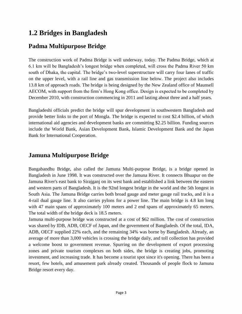
1.2 Bridges in Bangladesh
Padma Multipurpose Bridge
The construction work of Padma Bridge is well underway, today. The Padma Bridge, which at
6.1 km will be Bangladesh’s longest bridge when completed, will cross the Padma River 50 km
south of Dhaka, the capital. The bridge’s two-level superstructure will carry four lanes of traffic
on the upper level, with a rail line and gas transmission line below. The project also includes
13.8 km of approach roads. The bridge is being designed by the New Zealand office of Maunsell
AECOM, with support from the firm’s Hong Kong office. Design is expected to be completed by
December 2010, with construction commencing in 2011 and lasting about three and a half years.
Bangladeshi officials predict the bridge will spur development in southwestern Bangladesh and
provide better links to the port of Mongla. The bridge is expected to cost $2.4 billion, of which
international aid agencies and development banks are committing $2.25 billion. Funding sources
include the World Bank, Asian Development Bank, Islamic Development Bank and the Japan
Bank for International Cooperation.
Jamuna Multipurpose Bridge
Bangabandhu Bridge, also called the Jamuna Multi-purpose Bridge, is a bridge opened in
Bangladesh in June 1998. It was constructed over the Jamuna River. It connects Bhuapur on the
Jamuna River's east bank to Sirajganj on its west bank and established a link between the eastern
and western parts of Bangladesh. It is the 92nd longest bridge in the world and the 5th longest in
South Asia. The Jamuna Bridge carries both broad gauge and meter gauge rail tracks, and it is a
4-rail dual gauge line. It also carries pylons for a power line. The main bridge is 4.8 km long
with 47 main spans of approximately 100 meters and 2 end spans of approximately 65 meters.
The total width of the bridge deck is 18.5 meters.
Jamuna multi-purpose bridge was constructed at a cost of $62 million. The cost of construction
was shared by IDB, ADB, OECF of Japan, and the government of Bangladesh. Of the total, IDA,
ADB, OECF supplied 22% each, and the remaining 34% was borne by Bangladesh. Already, an
average of more than 3,000 vehicles is crossing the bridge daily, and toll collection has provided
a welcome boost to government revenue. Spurring on the development of export processing
zones and private tourism complexes on both sides, the bridge is creating jobs, promoting
investment, and increasing trade. It has become a tourist spot since it's opening. There has been a
resort, few hotels, and amusement park already created. Thousands of people flock to Jamuna
Bridge resort every day.
Page 4
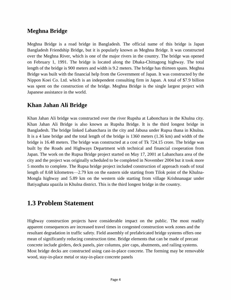
Meghna Bridge
Meghna Bridge is a road bridge in Bangladesh. The official name of this bridge is Japan
Bangladesh Friendship Bridge, but it is popularly known as Meghna Bridge. It was constructed
over the Meghna River, which is one of the major rivers in the country. The bridge was opened
on February 1, 1991. The bridge is located along the Dhaka-Chittagong highway. The total
length of the bridge is 900 meters and width is 9.2 meters. The bridge has thirteen spans. Meghna
Bridge was built with the financial help from the Government of Japan. It was constructed by the
Nippon Koei Co. Ltd. which is an independent consulting firm in Japan. A total of $7.9 billion
was spent on the construction of the bridge. Meghna Bridge is the single largest project with
Japanese assistance in the world.
Khan Jahan Ali Bridge
Khan Jahan Ali bridge was constructed over the river Rupsha at Labonchara in the Khulna city.
Khan Jahan Ali Bridge is also known as Rupsha Bridge. It is the third longest bridge in
Bangladesh. The bridge linked Labanchara in the city and Jabusa under Rupsa thana in Khulna.
It is a 4 lane bridge and the total length of the bridge is 1360 meters (1.36 km) and width of the
bridge is 16.48 meters. The bridge was constructed at a cost of Tk 724.15 crore. The bridge was
built by the Roads and Highways Department with technical and financial cooperation from
Japan. The work on the Rupsa Bridge project started on May 17, 2001 at Labanchara area of the
city and the project was originally scheduled to be completed in November 2004 but it took more
5 months to complete. The Rupsa bridge project included construction of approach roads of total
length of 8.68 kilometres—2.79 km on the eastern side starting from Tilok point of the Khulna-
Mongla highway and 5.89 km on the western side starting from village Krishnanagar under
Batiyaghata upazila in Khulna district. This is the third longest bridge in the country.
1.3 Problem Statement
Highway construction projects have considerable impact on the public. The most readily
apparent consequences are increased travel times in congested construction work zones and the
resultant degradation in traffic safety. Field assembly of prefabricated bridge systems offers one
mean of significantly reducing construction time. Bridge elements that can be made of precast
concrete include girders, deck panels, pier columns, pier caps, abutments, and railing systems.
Most bridge decks are constructed using cast-in-place concrete. The forming may be removable
wood, stay-in-place metal or stay-in-place concrete panels
Page 5
The great majority of bridges built in Bangladesh have a concrete deck slab. Most of these slabs
are cast-in-place (CIP). Public inconvenience and loss of income during bridge construction and
rehabilitation have prompted exploration of rapid construction methods. Cast-in-place(CIP)
bridge deck slab represents a significant part of construction or rehabilitation of stringer-type
bridge superstructures, as much of the construction time is consumed informing, placement and
tying of steel reinforcement, and placement and curing of CIP concrete.
CIP deck is common because of the relatively low initial cost, without allowance for cost of
traffic delay, and because of its ability to tolerate errors in girder placement positions and top-of-
girder elevations.
Many bridge deck construction systems have been developed either for the construction of new
bridges or for the rehabilitation of deteriorated bridge decks. Among these systems is the
conventional precast pre-stressed concrete deck panel system. The precast panels are butted
against each other without any continuity between them. They are set on variable thickness
bearing strips to allow for elevation adjustment. This system has the advantage of high
construction speed compared to the full-depth cast-in-place deck system because of elimination
of field forming.
1.4 Purposes behind implementation of a new bridge deck
system in Bangladesh
I. Geological History of Bangladesh:
The most ancient geographical description of the Ganges delta forming Bangladesh is found in
the Claudius Ptolemy’s map sketched in 150 AD. The sketched map shows the clear existence of
the Himalayan highlands and the river systems those originated from it. This surely indicates the
ancient importance of this geographical location in the global context. Further the recorded
information about its river systems and waterways are known in the sketches found in the Aine-
e-Akbari (1582 AD).
The rivers in Bangladesh form the most significant aspects of landscape of the country. Abul
Fazal, the historian of 1582 A.D., of the court of Mughal Emperor Akbar, remarked that rivers in
Bengal are numerous and these have great influence on the lives of the people of the country.
The drainage systems in Bangladesh are very much complex; and such of those are not found
anywhere in the world (Alam et al. 1990). These types of drainages were bewildering and
surprising for foreign travellers in the past.

Page 6
Figure 1.1: A Woodblock Ptolemaic Map, “Decima Asiae Tabula”, ‘Geographie Opus
Novissima’ (Strasbourg: J. Schott, 1513)
James Rennell’s map of Bengal and Bahar (1778) was the first scientifically prepared map of the
Ganges- Brahmaputra (Jamuna)-Meghna basin in a time even before the establishment of the
modern prime meridian, based at the Royal Observatory, Greenwich which was established by
Sir George Airy only in 1851.
The local need to travel from one part of this land to the other was, however, limited in the
Mughal era (1526-1857 AD). The dependence on river systems was significant not only for
transport but also for the defense of the important forts and townships. However, in the wake of
imperial expansion and increasing interaction with Europe, it became increasingly important to
establish fixed links over its great river systems.
The geological formation of the country, a low lying delta formed by recent deposits on the flood
plains of the Ganges-Brahmapurtra-Meghna river systems, with hundreds of tributaries,
distributaries and water bodies, posed a big challenge to the Civil Engineers in design,
construction and maintenance of an uninterrupted country wide road-rail network. Establishment
of fixed links using bridges required to have deep understanding of the river systems for
Page 7
achieving sustainability in the long run. The bridges constructed in the past were mostly located
in the Ganges-Brahmaputra-Meghna basin but a fewin the folded flanks of Arakan-Myanmar
hills. The design and construction were taking pl ace since 1870 to date after giving
appropriate attention to the geomorphological features of the country using the knowledge
available at the time of those constructions.
II. Geological information for the River Systems:
The Geological Survey of Bangladesh has been studying the major drainage system of 1778,
1874-77 and 1985 to publish the historical shifts of the River System in a map of Bangladesh in
the scale of 1:1,000,000.Along with the study of major fault systems, the drainage systems
analysis may indicate the probable causes of floods for geo-structural reasons beside
hydrological and climate change considerations. It is expected, the geological aspects mainly
related to the development of drainage systems, as studied will be able to identify their nature of
influence on the flood flow and the landscape will be available.
Hard paucity in the historic data on local climatic conditions, particularly the earthquake, wind
speed, airborne salinity limited the designers to come out with more efficient designs. The
engineers were forced towards conservative designs with the projections they conceived from
their professional judgments. Bangladesh Meteorological Department has 34 weather stations to
monitor temperature, wind speed and humidity all over the country, only since 1993. Before that
observations were limited only at a few stations.
III. Choice of Materials and Properties of Materials:
The local aggregates used for concrete production is softer and somewhat lighter
(Akhteruzzaman and Hasnat 1983, Islam et al. 2015) than those used in other parts of the world.
Ishtiaq Ahmad and Roy (2013) reports larger creep in brick aggregate concrete. Similar
properties are also expected in stones (other than hard rock) of Bangladesh origin. This needs to
be checked for deriving the basic parameters in bridge design and construction. To reduce the
foundation load for achieving longer spans, smaller foundation sizes, smaller design scour
depths, it is important to reduce the self weight of the structure. Consideration of efficient
structural form and choice of structural steel sections can be a step forward to solve the design
catch. However, to reduce the life cycle cost, it is important to reduce the cost required for
corrosion protection. Thus, use of weathering steel should be considered thoroughly to reduce
the life cycle cost to arrive at an efficient structural form. Measurement of air borne salinity and
atmospheric exposure test data on different grades of weathering steel will infer about the
applicability of new generation steel for different climatic conditions. The application of such

Page 8
steel in coastal zones for high air borne salinity content may not be suitable as was seen in other
countries while prospect in use of this material for rest of the country needs to be immediately
explored.
IV. Construction Technology and Choice of Bridge Forms:
Cost of a project depends significantly on the availability of construction technology, the time
required for completing the project and thereby bringing it to service. Bangladesh is now in a
transition towards modernization in pile driving techniques and development of an efficient
methodology for erection of longer spans. This will obviously dictate the choice of bridge forms.
An achievement is still waiting.
V. Appropriate Technology for Strengthening:
Any bridge designed today will deteriorate with time or a requirement may evolve to enhance its
performance level. Strengthening for performance enhancement is a world-wide recognized
terminology but it needs to be thoroughly customized for local materials and climatic conditions.
Fundamental parameters governing the strengthening design needs to be re-determined or re-assured
from first-hand experimental measurements.
VI. Overloading and Lack of Monitoring:
The traffic congestion, transport cost and toll prices encourage the transport owners to carry
excess cargo than allowed. This excess cargo does have first impact on the bridge deck then on
the bearings and expansion joints. Lack of monitoring worsens the situation. Bangladesh is yet to
achieve a benchmark in bridge health monitoring through visual and instrumental observations
(Amin et al. 2015).
1.5 Benefits of this System
In addition to high construction speed, full-depth, precast panel systems have many advantages,
such as high quality plant production under tight tolerances, low permeability, much reduced
volume changes due to shrinkage and temperature change during initial curing, and low
maintenance cost.
Page 9
Development of a full-depth, precast-concrete bridge deck panel system with riding quality
suitable for high-speed traffic contact would be a major achievement. It would help produce a
significant contribution towards developing a totally prefabricated bridge construction system in
our country. Elimination of deck panel system post-tensioning, would also contribute to avoiding
delays and use of specialty subcontractors. Previous research has resulted in implementation of
post-tensioned and overlaid systems for connection durability and ride quality.
Precast and pre-stressed concrete composite bridge deck panels are used with cast-in-place
concrete to provide a convenient and cost effective method of construction for concrete bridge
decks. The panels are usually precast at a manufacturing plant. They are trucked to the bridge
construction site and lifted by cranes onto concrete or steel girders. There, they span the opening
between girders and serve as permanent forms for the cast-in-place concrete topping that
completes the bridge deck. The precast concrete panels and concrete topping become composite
and the panels contain all of the required positive moment reinforcement between girders.
Precast and pre-stressed concrete composite bridge deck panels will be referred to, in this report,
as simply as "deck panels."Deck panels are similar to other pre-stressed concrete composite
members with regard to applications and design considerations, there are however, situations that
are unique to composite deck panels due to the way the panels are produced and used.
1.6 Design Considerations
The design of precast pre-stressed concrete composite bridge deck panels must include an
analysis of the panels for stresses due to handling and during construction as well as ultimate
strength of the composite section. Design drawings should show every aspect of production and
installation of the composite deck panels, including storage instructions, bearing details, and all
other special considerations. Drawings must include all information contained on the design
drawings as well as any special information necessary for production. Composite deck panel
lengths should be carefully selected with consideration given to tolerances for girder horizontal
sweep in order to achieve proper bearing. These are the special cases which should be carefully
studied.

Page 10
1.7 Choice of Design Code and Limitations
At present, no independent national design code/standard for bridges in Bangladesh exists. The
current trend is to use mainly the American Association of States Highway and Transportation
Officials (AASHTO) Specifications; in which the different designers use different editions
varying between 1992 and 2007. The other specialist literatures are also used. In special cases,
the British Standard (BS) 5400 (1978) has been followed, for example, in preparing the Jamuna
Design Specification for the Jamuna Multipurpose Bridge (Sobhan and Amin 2010). Indian
Roads Congress (IRC) specifications are also often consulted. Design of second Kachpur,
Meghna and Gumti bridges followed largely the Japan Road Association (JRA) provisions after
consulting the Bangladesh National Building Code 1993 (BNBC 1993) for finding the wind and
earthquake loading of bridges. However, BNBC (1993) is meant for buildings while AASHTO,
BS and JRA codes do not consider the local conditions.
Seismic design for bridges usually considers two levels of earthquake, namely Operating Level
Earthquake (OLE/ Level I) and Contingency Level Earthquakes (CLE/ Level II) earthquakes.
OLE has a return period of 100 years with a 65% probability of being exceeded during that
period. CLE has a return period of 475 years with a 20% probability of being exceeded during
the design life of the bridge (100 years) as used in the design of the Padma Bridge (Sham 2015).
However, in the second Meghna Bridge Project designs, BNBC (1993) response spectra was
judged to be close to AASHTO LRFD (2007). Calculations yielded a response spectra for the
Meghna site a bit different than that for the Padma Bridge. Furthermore, BNBC (1993) was
found to be higher by about 50% in short-periodic region (Tatsumi et al. 2015), compared to
Level-1 Type- II soil profile recorded by JRA (2012). At this moment, in absence of any design
code for bridges, there exists no specific guideline to consider for earthquake loading.
Bangladesh National Building Code was prepared in 1993 based on limited wind speed
measurement information. After 1993, thirty four observation stations are in service to record
three hourly observations for wind. A synthesis of these data may help in updating the basic
wind speed map. However, when bridges are constructed in open areas, the terrain exposure
needs to be adequately judged based on local observations or model studies including dynamic
effects. Some efforts are needed in these directions.
Guideline values on the consideration of the effect of daily and annual temperature differences
are needed to be prescribed. So reconsideration is warranted, particularly for the design of box
girder, setting out requirements and expansion-contraction measures. These measurements are
also important to ensure the durability properties of rubber and ageing behavior of rubber, the
essential component in all modern bridge bearings and expansion joints. In addition, in design it
is to be considered that more than 60% of time of a year, in Bangladesh, near rivers, the relative
humidity stays above 80%. This calls for use of dense concrete and effective measures for
corrosion protection.
Page 11
1.8 Objective & Scope
The objectives of this research were to develop the following:
(1) Design guidelines for fabrication and construction of full-depth, precast, concrete bridge
deck panel systems with the use of post-tensioning; and
(2) Connection/ joint details for the innovative new deck panel system.
Certain steps were undertaken in order to achieve the above goals, and they are as follows:
STEP 1: Relevant literature on bridge projects with full-depth, precast concrete panel systems
were collected, reviewed and summarized. Additional information on issues related to these
systems such as grouting materials, shear-pocket details and precast panel-to-panel connections
were collected and studied. Also, similar practices and other information related to the design,
fabrication, and installation of full-depth, precast concrete bridge deck panel systems were
accumulated and analyzed.
STEP 2: An international survey was prepared and sent to bridge divisions of state DOTs in
United States, Canada, Japan, China, Germany, Dubai, India, Europe and Australia, as well as
international consulting firms both public and private, precast concrete producers and exporters,
and members of the Bangladesh Bridge Authority (BBA), and the Roads And Highways
Department in Dhaka, Bangladesh.
STEP 3: Connection details for full-depth precast concrete deck systems, which can be used
with high strength steel and pre-stressed/ reinforced concrete girders, were developed and
evaluated theoretically. These details satisfy the following conditions: high durability, low
construction time, good riding quality, easy transportation of moveable parts, low maintenance
cost and high structural performance. The focus was on deck panel systems with longitudinal
post-tensioning. The connection or joint details included panel-to-panel and panel-to-
superstructure connections.
STEP 4: Guidelines for design, detailing, fabrication, and construction of full-depth precast
concrete bridge deck panel systems were developed.
STEP 5: Specification language and commentary for the AASHTO LRFD Bridge Design
Specifications necessary to implement full-depth, precast concrete bridge deck panel systems
were developed.

Page 12
Chapter- 02
LITERATURE REVIEW

Page 13
2.1 What is a BRIDGE?
A bridge is a structure built to span physical obstacles without closing the way underneath such
as a body of water, valley, or road, for the purpose of providing passage over the obstacle. There
are many different designs that each serve a particular purpose and apply to different situations.
Designs of bridges vary depending on the function of the bridge, the nature of the terrain where
the bridge is constructed and anchored, the material used to make it, and the funds available to
build it.
Figure 2.1: Cable Stayed Bridge, Shah Amanat, Chittagong
Page 14
2.2 Early History of Bridges
Bridge is a structure that provides passage over obstacles such as valleys, rough terrain or bodies
of water by spanning those obstacles with natural or manmade materials. They first begun be
used in ancient times when first modern civilizations started rising in the Mesopotamia. From
that point on, knowledge, engineering, and manufacture of new bridge building materials spread
beyond their borders, enabling slow but steady adoption of bridges all across the world.
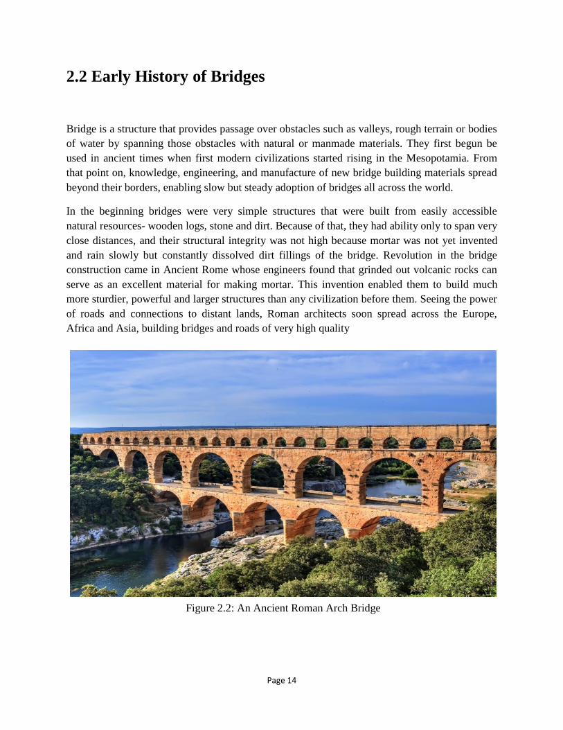
In the beginning bridges were very simple structures that were built from easily accessible
natural resources- wooden logs, stone and dirt. Because of that, they had ability only to span very
close distances, and their structural integrity was not high because mortar was not yet invented
and rain slowly but constantly dissolved dirt fillings of the bridge. Revolution in the bridge
construction came in Ancient Rome whose engineers found that grinded out volcanic rocks can
serve as an excellent material for making mortar. This invention enabled them to build much
more sturdier, powerful and larger structures than any civilization before them. Seeing the power
of roads and connections to distant lands, Roman architects soon spread across the Europe,
Africa and Asia, building bridges and roads of very high quality
Figure 2.2: An ancient Roman Arch Bridge
Figure 2.2: An Ancient Roman Arch Bridge

Page 15
One of the defining successes of Roman bridge architecture was their discovery of arches. By
using this type of building, load forces of the bridge were conveyed to move along the curve of
the arch, meeting with the ground where they were canceled by supports on the end of the arch.
Because of that, Romans were able to create bridges that were much lighter than before and were
able to hold load that was twice as heavy as the bridge itself. In construction of their numerous
aqueducts, Roman architects even managed to create water carrying bridges with multiple arched
tiers that reached incredible heights!
Modern bridges are usually made with the combination of concrete, irons and cables, and can be
built from very small sizes to incredible lengths that span entire mountains, rough landscapes,
lakes and seas.
Page 16
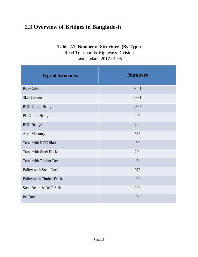
2.3 Overview of Bridges in Bangladesh
Table 2.1: Number of Structures (By Type)
Road Transport & Highways Division
Last Update: 2017-01-05
Type of Structures
Numbers
Box Culvert 9441
Slab Culvert 3991
RCC Girder Bridge 2387
PC Girder Bridge 405
RCC Bridge 244
Arch Masonry 318
Truss with RCC Slab 30
Truss with Steel Deck 204
Truss with Timber Deck 6
Bailey with Steel Deck 973
Bailey with Timber Deck 23
Steel Beam & RCC Slab 230
PC Box 5

Page 17
2.3.1 CULVERTS A culvert is a structure that allows water to flow under a road, railroad, trail, or similar
obstruction from one side to the other side. Typically embedded so as to be surrounded by soil, a
culvert may be made from a pipe, reinforced concrete or other material. In the United Kingdom
the word can also be used for a longer artificially buried watercourse. A structure that carries
water above land is known as an aqueduct.
Culverts are commonly used both as cross-drains for ditch relief and to pass water under a road
at natural drainage and stream crossings. A culvert may be a bridge-like structure designed to
allow vehicle or pedestrian traffic to cross over the waterway while allowing adequate passage
for the water. Culverts come in many sizes and shapes including round, elliptical, flat-bottomed,
pear-shaped, and box-like constructions. The culvert type and shape selection is based on a
number of factors including requirements for hydraulic performance, limitation on upstream
water surface elevation, and roadway embankment height.
2.3.1 a) Box Culvert Four-sided culverts are typically referred to as box culverts.
• Standard box sizes: 3’ x 2’ to 12’ x 12’ in 1’ span and rise increments.
• Typically come in 6’ and 8’ spans.
• Custom box sizes: Nonstandard sizing is permissible and must be designed per project design
specification.

Page 18
2.3.1 b) Slab Culvert
This is the simplest kind of culvert design, and is mostly found in the rural regions of
Bangladesh. The contraction method is very simple. This technique usually involves a piece of
slab laid over a narrow water body (for example canal) flowing between two pieces of land. Slab
culverts may be used for pedestrian or vehicle crossing. While this structure is significantly
cheap compared to other culverts or bridges, it is also the least structurally reliable.
Figure 2.3: Box Culvert
Page 19
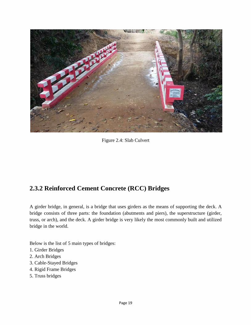
Figure 2.4: Slab Culvert
2.3.2 Reinforced Cement Concrete (RCC) Bridges
A girder bridge, in general, is a bridge that uses girders as the means of supporting the deck. A
bridge consists of three parts: the foundation (abutments and piers), the superstructure (girder,
truss, or arch), and the deck. A girder bridge is very likely the most commonly built and utilized
bridge in the world.
Below is the list of 5 main types of bridges:
1. Girder Bridges
2. Arch Bridges
3. Cable-Stayed Bridges
4. Rigid Frame Bridges
5. Truss bridges

Page 20
Figure 2.5: Reinforced Cement Concrete (RCC) Girder, Sangu Bridge, Bandarban
2.3.3 Girder Bridges
Girder bridges have existed for millennia in a variety of forms depending on resources available.
A girder bridge, in general, is a bridge that uses girders as the means of supporting the deck. A
bridge consists of three parts: the foundation (abutments and piers), the superstructure (girder,
truss, or arch), and the deck. A girder bridge is very likely the most commonly built and utilized
bridge in the world. Its basic design, in the most simplified form, can be compared to a log
ranging from one side to the other across a river or creek. In modern girder steel bridges, the two
most common shapes are plate girders and box-girders.
2.3.4 Reinforced Cement Concrete (RCC) Girder Bridges An RCC girder bridge is one where the girders are made from reinforced cement concrete and
are a widely used bridge system for short to medium span (<20m)highway bridges due to its
moderate self-weight, structural efficiency, ease of fabrication, low maintenance etc. Durable
and sustainable bridges play an important role for the socio-economic development of the nation.
Page 21
Owners and designers have long recognized the low initial cost, low maintenance needs and long
life expectancy of RCC concrete bridges.
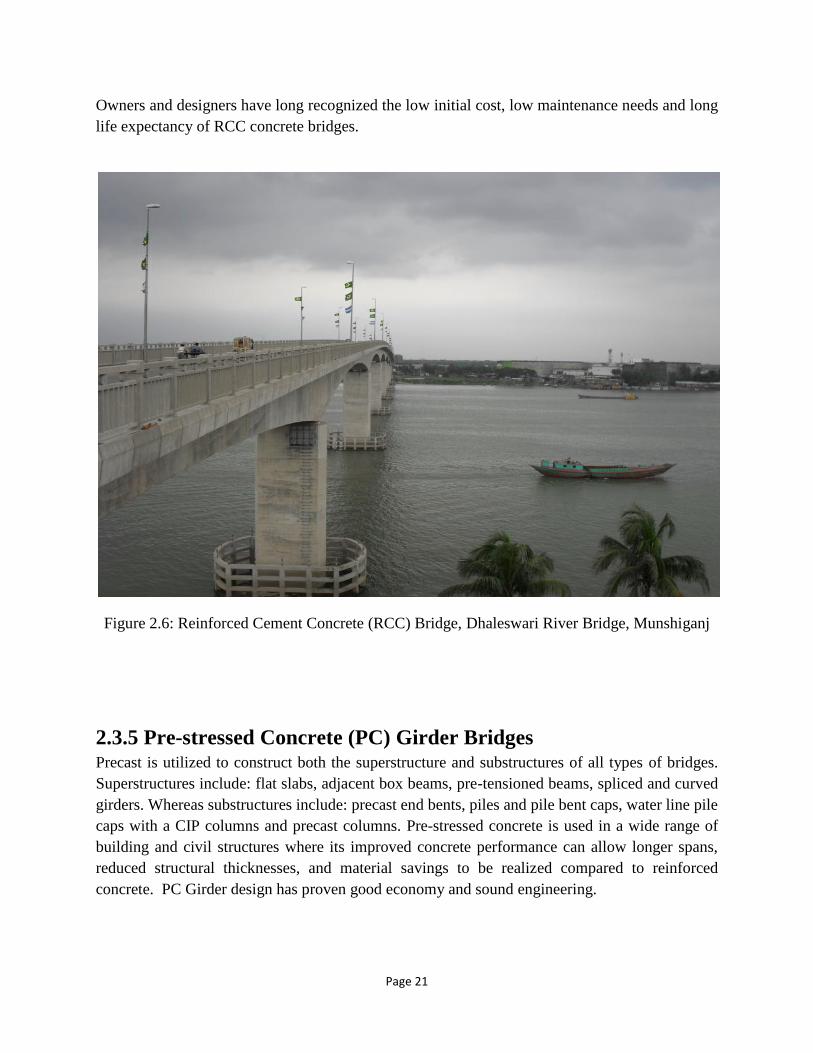
Figure 2.6: Reinforced Cement Concrete (RCC) Bridge, Dhaleswari River Bridge, Munshiganj
2.3.5 Pre-stressed Concrete (PC) Girder Bridges Precast is utilized to construct both the superstructure and substructures of all types of bridges.
Superstructures include: flat slabs, adjacent box beams, pre-tensioned beams, spliced and curved
girders. Whereas substructures include: precast end bents, piles and pile bent caps, water line pile
caps with a CIP columns and precast columns. Pre-stressed concrete is used in a wide range of
building and civil structures where its improved concrete performance can allow longer spans,
reduced structural thicknesses, and material savings to be realized compared to reinforced
concrete. PC Girder design has proven good economy and sound engineering.

Page 22
Proven Economy: low initial cost, minimum maintenance, fast & easy construction, minimum
traffic interruption. Sound Engineering: simple design, minimum span/depth ratio, assured
plant quality, durable, aesthetic value.
b) Pre-tensioning Process of a
Girder
Figure 2.7: Tensioning Process
a) Post-tensioning Process of a
Girder

Page 23
Figure 2.8: Pre-stressed Concrete (PC) Girder Bridge, Mohipur-Alipur, Patuakhali
2.3.6 Arch Bridges An arch bridge is a bridge with abutments at each end shaped as a curved arch. Arch bridges
work by transferring the weight of the bridge and its loads partially into a horizontal thrust
restrained by the abutments at either side. A viaduct (a long bridge) may be made from a series
of arches, although other more economical structures are typically used today.
Stone, brick and other such materials are strong in compression and somewhat so in shear, but
cannot resist much force in tension. As a result, masonry arch bridges are designed to be
constantly under compression. Each arch is constructed over a temporary false work frame,
known as a centering. In the first compression arch bridges, a keystone in the middle of the
bridge bore the weight of the rest of the bridge. The more weight that was put onto the bridge,
the stronger its structure became. Masonry arch bridges use a quantity of fill material (typically
compacted rubble) above the arch in order to increase this dead-weight on the bridge and prevent
tension from occurring in the arch ring as loads move across the bridge. Other materials that
were used to build this type of bridge were brick and unreinforced concrete. When masonry (cut
Page 24
stone) is used the angles of the faces are cut to minimize shear forces. Where random masonry
(uncut and unprepared stones) is used they are mortared together and the mortar is allowed to set
before the false-work is removed.
Traditional masonry arches are generally durable, and somewhat resistant to settlement or
undermining. However, relative to modern alternatives, such bridges are very heavy, requiring
extensive foundations. They are also expensive to build wherever labor costs are high.
Structurally there are four basic arch types:
1. Hinge-less
2. Two-hinged
3. Three hinged
4. Tied arches
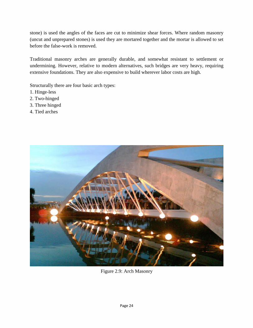
Figure 2.9: Arch Masonry

Page 25
Figure 2.10: Arch Masonry, Mir Kadim Bridge, Munshiganj
2.3.7 Truss Bridges
A truss bridge is a bridge whose load-bearing superstructure is composed of a truss, a structure
of connected elements usually forming triangular units. The connected elements (typically
straight) may be stressed from tension, compression, or sometimes both in response to dynamic
loads. This kind of bridge carries pedestrians, pipelines, automobiles, trucks, light rail, heavy rail
etc. The span range is short to medium –usually not very long unless it is continuous. Truss
Bridges maybe made out of timber, iron, steel, reinforced concrete and pre-stressed concrete.
Page 26
The nature of a truss allows the analysis of the structure using a few assumptions and the
application of Newton's laws of motion according to the branch of physics known as statics. For
purposes of analysis, trusses are assumed to be pin jointed where the straight components meet.
This assumption means that members of the truss (chords, verticals and diagonals) will act only
in tension or compression.
Figure 2.12: Truss with Reinforced Concrete Cement (RCC) Slab, Sherpur
Figure 2.11: The Internal Parts of a Truss Bridge

Page 27
Figure 2.13: Truss with Timber Decks, Shah Amanat Bridge, Chittagong
Figure 2.14: Truss with Steel Deck, Boalia Bazar, Nalchiti, Barisal

Page 28
2.3.8 Bailey Bridges The Bailey bridge is a type of portable, pre-fabricated, truss bridge. It was developed by the
British during World War II for military use and saw extensive use by British, Canadian and the
American military engineering units. It was named after Sir D. Bailey (1901-85), the English
engineer who designed it.
A Bailey bridge had the advantages of requiring no special tools or heavy equipment to
assemble. The wood and steel bridge elements were small and light enough to be carried in
trucks and lifted into place by hand, without requiring the use of a crane. The bridges were
strong enough to carry tanks. Bailey bridges continue to be extensively used in civil engineering
construction projects and to provide temporary crossings for foot and vehicle traffic.
The basic bridge consists of three main parts. The bridge's strength is provided by the panels on
the sides. The panels are 10-foot-long (3.0 m), 5-foot-high (1.5 m), cross-braced rectangles that
each weigh 570 pounds (260 kg), and can be lifted by six men. The panel was constructed of
welded steel. The top and bottom chord of each panel had interlocking male and female lugs into
which engineers could inset panel connecting pins
The floor of the bridge consists of a number of 19-foot-wide (5.8 m) transoms that run across the
bridge, with 10-foot-long (3.0 m) stringers running between them on the bottom, forming a
square. Transoms rest on the lower chord of the panels, and clamps hold them together. Stringers
are placed on top of the completed structural frame, and wood planking is placed on top of the
stringers to provide a roadbed. Ribands bolt the planking to the stringers. Later in the war, the
wooden planking was covered by steel plates, which were more resistant to the damage caused
by tank tracks.
Each unit constructed in this fashion creates a single 10-foot-long (3.0 m) section of bridge, with
a 12-foot-wide (3.7 m) roadbed. After one section is complete it is typically pushed forward over
rollers on the bridgehead, and another section built behind it. The two are then connected
together with pins pounded into holes in the corners of the panels.
For added strength several panels (and transoms) can be bolted on either side of the bridge, up to
three. Another solution is to stack the panels vertically. With three panels across and two high,
the Bailey Bridge can support tanks over a 200-foot span (61 m). Footways can be installed on
the outside of the side-panels; the side-panels form an effective barrier between foot and vehicle
traffic and allow pedestrians to safely use the bridge.
A useful feature of the Bailey bridge is its ability to be launched from one side of a gap. In this
system the front-most portion of the bridge is angled up with wedges into a "launching nose" and
most of the bridge is left without the roadbed and ribands. The bridge is placed on rollers and
simply pushed across the gap, using manpower or a truck or tracked vehicle, at which point the
roller is removed (with the help of jacks) and the ribands and roadbed installed, along with any
additional panels and transoms that might be needed.

Page 29
►►Construction Process of Bailey Bridges
Bailey bridges are built on site from a pre-engineered system of ready-to-assemble components.
Utilizing standardized prefabricated components, Bailey bridges can be built to match a wide
range of vehicular bridging applications. Because of their excellent versatility and overall value,
thousands of Bailey bridges have been installed throughout the world.
►Features
• Adaptable - pre-engineered to match each application
• Fast - modular stocked components, open to traffic in days
• Lower Cost - an alternative to custom designed bridges
• Easy - to handle, transport, assemble, install and reuse
►Materials and finishes
Domestic steel is used throughout. Most load-bearing components use low-alloy, high-tensile
ASTM A242 steel with a yield point of 50,000 psi. Excellent corrosion resistance is achieved
with an inorganic zinc silicate coating. Final color is lusterless light gray. Hot dipped galvanized
is also available.
►Assembly and Installation
Most Bailey bridges are assembled and installed in a matter of days by a small crew. Common
hand tools are utilized. All connections are pinned, bolted or clamped. No welding is necessary.
Disassembly is similarly easy, and components can be stored in minimal space until reused.
Bailey bridges are often installed by the cantilever launching method, in which the assembled
bridge together with a “launching nose” is rolled out across the gap, without false work or heavy
equipment. The cantilever method allows bridges to be quickly erected over rivers or deep
gorges. Additionally, some Bailey bridges may be hoisted into place by crane.
Page 30
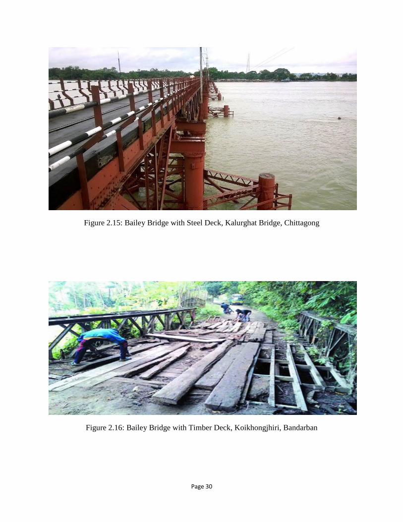
Figure 2.15: Bailey Bridge with Steel Deck, Kalurghat Bridge, Chittagong
Figure 2.16: Bailey Bridge with Timber Deck, Koikhongjhiri, Bandarban
Page 31
2.3.9 Steel/ Concrete Composite Bridges
Steel/ concrete composite deck slab bridges, or River Bridges, can be constructed with effective
spans ranging from about 10 to 40 meters and skew angles of 45 degrees or more and can be
adapted to changes in structural height according to their longitudinal alignment. They are now
compatible with continuous girders, expanding their range of applications. River Bridges
(KCSB) have a greater potential to meet social needs, labor saving and speedup of onsite
construction works and the minimization of life cycle costs. This kind of design boasts the
following beneficial features:
1. Low structural height: From among all structural types, River Bridges can achieve the lowest
structural height.
2. Rapid construction: The construction weight of River Bridges is far lighter than that of
concrete-based bridges, so heavy equipment can be downsized. In addition, formwork and
scaffolding are no longer necessary as the bottom panels function as deck slab formwork,
resulting in the reduction of the construction work period.
3. Minimization of LCC: The RC deck slabs, which are of a highly durable structure, are almost
maintenance-free and also contribute to the minimization of life cycle costs.
4. Design ability: River Bridges can offer not only a slender appearance thanks to their low
structural height but also impressive landscaping design.
Page 32
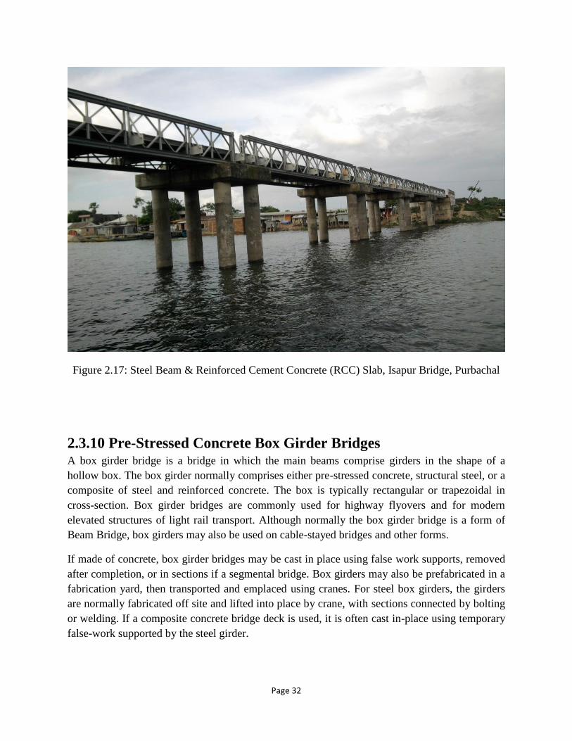
Figure 2.17: Steel Beam & Reinforced Cement Concrete (RCC) Slab, Isapur Bridge, Purbachal
2.3.10 Pre-Stressed Concrete Box Girder Bridges A box girder bridge is a bridge in which the main beams comprise girders in the shape of a
hollow box. The box girder normally comprises either pre-stressed concrete, structural steel, or a
composite of steel and reinforced concrete. The box is typically rectangular or trapezoidal in
cross-section. Box girder bridges are commonly used for highway flyovers and for modern
elevated structures of light rail transport. Although normally the box girder bridge is a form of
Beam Bridge, box girders may also be used on cable-stayed bridges and other forms.
If made of concrete, box girder bridges may be cast in place using false work supports, removed
after completion, or in sections if a segmental bridge. Box girders may also be prefabricated in a
fabrication yard, then transported and emplaced using cranes. For steel box girders, the girders
are normally fabricated off site and lifted into place by crane, with sections connected by bolting
or welding. If a composite concrete bridge deck is used, it is often cast in-place using temporary
false-work supported by the steel girder.
Page 33
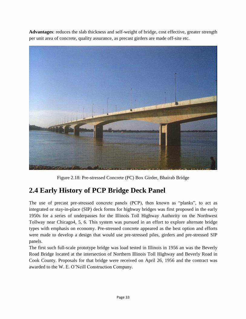
Advantages: reduces the slab thickness and self-weight of bridge, cost effective, greater strength
per unit area of concrete, quality assurance, as precast girders are made off-site etc.
Figure 2.18: Pre-stressed Concrete (PC) Box Girder, Bhairab Bridge
2.4 Early History of PCP Bridge Deck Panel
The use of precast pre-stressed concrete panels (PCP), then known as “planks”, to act as
integrated or stay-in-place (SIP) deck forms for highway bridges was first proposed in the early
1950s for a series of underpasses for the Illinois Toll Highway Authority on the Northwest
Tollway near Chicago4, 5, 6. This system was pursued in an effort to explore alternate bridge
types with emphasis on economy. Pre-stressed concrete appeared as the best option and efforts
were made to develop a design that would use pre-stressed piles, girders and pre-stressed SIP
panels.
The first such full-scale prototype bridge was load tested in Illinois in 1956 an was the Beverly
Road Bridge located at the intersection of Northern Illinois Toll Highway and Beverly Road in
Cook County. Proposals for that bridge were received on April 26, 1956 and the contract was
awarded to the W. E. O’Neill Construction Company.
Page 34
Six tests were performed on the bridge that included piles, girders and slabs. Additional tests
were conducted at Lehigh University on portions of composite deck slab. In conclusion, the test
structure was subjected to severe loads at different stages of construction. The resulting girder
and slab moments were, in most instances, far in excess of design moments based on AASHO H-
20 truckloads plus impact. The maximum positive transverse moment in the slab was the
equivalent to that resulting from nearly seven times live plus impact loads. The maximum
negative transverse moment in the slab was over five times that of one live plus impact loading.
There can be no doubt that complete and positive composite action between the precast girders;
precast slabs and CIP slab prevailed throughout the tests.
Precast, pre-stressed deck panels have also been used as full depth deck replacements. An early
example of the use of PCP-FD is in the “Pintala Creek Bridge” in Alabama in the 1960s. Later,
in 1968, Gutswiller, M.J., Lee, R. H. and Scholer C. F., of Purdue University10, reviewed the
concept of using full depth precast and pre tensioned slabs which are placed on top of the girders,
then post–tensioned and tied mechanically to the underlying girders. Later this method was
extended in 1990’s for Maryland’s rural highways11. A system of 3 or 4 ft. wide precast/pre-
stressed concrete slabs placed adjacent to each other and post-tensioned laterally in place with a
CIP concrete topping. The Texas Highway Department constructed three PCP-PD bridges in
Grayson County, Texas, using a pre-stressed concrete SIP element in the deck similar to that
used in Illinois. These bridges were opened to traffic in August 196312. In 1970, a research
project was taken to determine the behavior of these three bridges. The researchers observed
that: The bridges were found to be in sound condition. The transverse cracks found over the
panel joints extended only halfway through the CIP concrete. The bridges were sounded for
delamination, and no delamination had occurred in the area of transverse cracks. The cores taken
through deck slab hold the bond between CIP and PCP secure, and direct shear test determined
the failure bond stress as 285 psi. In 1975, The Texas Transportation Institute produced four
research reports in connection with the use of the in the three 1963 Texas bridges12. The first
research (Report No. 145-1) reiterates what was described in the Transportation Research
Circular No. 181. No evidence of non composite action was found. Some transverse cracking
was found in the CIP deck that coincided with transverse butt joints between pre-stressed panels.
Core samples showed these cracks to extend approximately halfway through the CIP deck. The
second research (Report No. 145-2) investigated the development length of strands in similar
pre-stressed panels and observed the effect of cyclic loading. An average development length of
22 inches was required for the 3/8 inches diameter strands tensioned with a force of 13.75 kips,
and 34 inches was needed for the strands with 1⁄2 inch diameter tensioned with a force of 27.5
kips. Cyclic loading was found to have negligible effect on strand development length or panel
stiffness. Since the length of the shortest test panel was 68 inches, the full pre-stress force could
be developed in each case. When the 1⁄2 inch diameter strands were used in the 68 inches panels,
it was concluded that only a few inches near mid span received the full pre-stress force. The third
Page 35
research (Report No. 145-3) experimentally and theoretically investigated the ability of the pre-
stressed panel bridge to distribute wheel loads in a satisfactory manner and to behave as a
composite unit. The following conclusions were drawn:
1. The bond at the interface between the pre-stressed, precast panels and the CIP concrete
performed without distress under cyclic design loads and static failure loads.
2. Wheel loads were transferred and distributed across transverse panel joints satisfactorily.
3. It is feasible to design for composite action in a pre-stressed panel bridge of the type studied.
The fourth research (Report No. 145-4F) focused on failure of composite panels, subjected to
static and cyclic loads: Curves of load versus number of load cycles at failure, S-N curves, were
developed from fatigue tests. The panel with shear lugs consistently took more load cycles to
failure for loads ranging from 210 to 260 percent of design load. If the S-N curve for the panels
with no Z-bars is projected out along the abscissa, it will level out at about 10 million cycles at
200 percent of design load. No load lower than about 200 percent of design load, on that basis,
will damage the specimen. Kluge, R.W. and Sawyer H.A., at University of Florida13, conducted
extensive studies to determine the extent of interaction between CIP concrete topping and PCP
panels without mechanical connectors and to develop design criteria for this type of bridge deck
system. The investigation was divided into four series spanning from 1969 to 1973. They
concluded:
1. Design calculations for shear are unnecessary, since PCP/CIP acts as monolithic concrete
deck, as long as no foreign material is allowed in the panel.
2. Transverse reinforcement in the PCP panels should not be less than No. 3 bars at 12inches
centers.
3. Minimum embedment lengths, including the embedment of free strand-ends of PCP panels
should be: 3/8 inches strand, 62 inches; 7/16 inches strand, 80 inches; 1⁄2 inches strand, 100
inches.
The first comprehensive full-scale test of a bridge using stay-in-place precast pre-stressed
concrete panels was performed under service and overload conditions at Pennsylvania State
University by Barnhoff and Rainey14, 15. There were two 60 spans, one span with conventional
deck and the other span with PCP/CIP, both subjected to identical loading. The following
conclusions were drawn.
Page 36
1. The deck utilizing PCP panels was slightly more flexible than the conventional deck, thereby
allowing larger beam deflections, but resulting in smaller live load moments in the slab.
2. The slight difference in behavior of the decks does not justify a separate procedure to
determine design moments in decks with PCP panels.
3. Full composite action was developed between the CIP concrete and the PCP panels.
Mechanical shear connectors are not required if the plank surface is given a scored finish.
One of the objectives of the laboratory tests conducted by Barnoff and Rainey was to compare
different types of joints between the panels. Three different joint types were studied: a butt joint,
a beveled joint, and a U-joint. There were no significant differences in the structural performance
of panels made with these different joints. It should also be noted that simulated wheel loads of
80 kips applied directly over the joint were required to fail the panels. Several auxiliary studies
were also conducted. One of these was to determine the effect of deicing agents on the
deterioration of the bridge deck. Calcium chloride and sodium chloride were applied to the
bridge deck during the two winters that the bridge was in service. Half-cell readings were made
to determine the amount of salt penetration, and cores were taken to find the depth, which
showed that the depth of penetration was not sufficient to cause corrosion of reinforcing steel in
the two-year life of the bridge deck.
The PCI Bridge Committee, came up with “Tentative Design and Construction Specifications for
Bridge Deck Panels,” in 1978.
SIP panels have also been used to span longitudinally from supporting abutment to supporting
abutment instead of the more common use of spanning laterally from bridge girder to bridge
girder. In 1980, Hays, C.O. Jr., R.L. Cox and Obranic G.O. conducted a research on “Full Span
Form Panels for Short Span Highway Bridges” at the University of Florida17. The researchers
concluded that a minimum panel width of 122 cm (48 inches) be used and that an improved
detail with more positive transfer of shear from panels to supports was needed to reduce
deformation and cracking.
In 1981, Fagundo, Tabatabai, and Soongswang conducted research at the University of Florida to
determine the adequacy of the SIP panels with CIP topping composite deck system18. They
concluded:
Test results indicate that slabs that were repaired and provided with positive bearing, regained of
all their original stiffness. It is believed that, in bridge decks with positive bearing provided
Page 37
under the panel, the concentration of the shear stresses on the CIP portion near the ends of the
panel is reduced and these decks have less maintenance problems than similar decks without
positive bearing. In 1982, a survey of the State Highway Departments by the PCI Bridge
Committee showed that 21 states used the panels regularly and another seven states were trying
the method through bidding options or were developing details prior to trial projects.
Also in 1982, research performed at the University of Texas at Austin by Bieschke and Klingner
on full-scale bridge specimens indicated that there was no local or global difference in the
performance of decks constructed using SIP panels with or without strand extensions19.
The use of strand extensions would later be addressed in the PCI Bridge Design Manual of 1997.
There is a significant implication to strand extensions, which require the fabrication to install
forms in the bed between each panel thereby increasing fabrication cost. If there is no strand
extension, the panels may be cast in a single, long slab and subsequently cut to length when the
concrete reaches transfer length. Strand extensions are generally not recommended. In 1987, the
PCI committee on bridges presented guidelines for the design, manufacture and erection of PCP-
PD panels, where suggestions were given for the dimensioning and detailing of panels,
techniques for casting panels and helpful ideas in the handling, shipping and erection of panels
A 1986 survey conducted by PCI contacted all State Highway Departments in the United States,
a number of Tollway and Transportation Authorities, and PCI member plants to determine the
contemporary specifications and method of production for PCP. This survey and also the
research mentioned earlier were compiled, studied and investigated by Ross Bryan Associates, a
PCI commissioned consultant, producing a guideline, “Recommended Practice for Precast Pre-
stressed Concrete Composite Bridge Deck Panels,” in 1988.
In 1993, Ahmad Idriss Talal of University of Illinois at Chicago surveyed full depth precast
panels for deck replacement22, 23. Out of 51 Department of Transportation-DOT’s that
responded to the survey, 10 were using the system, 41 were not using the system and 43 DOTs
were interested in using the system while 8 were not interested.
In 1994, Ramirez and Kumar at the Purdue University, West Lafayette, Indiana, investigated the
interface horizontal shear strength in composite decks with partial-depth precast concrete
panels24. They concluded that pre-stressed deck panels with a broom-finished surface do not
require horizontal shear connectors if the normal horizontal shear stress is less than 116 psi (0.8
MPa).
Page 38
In 1995, Klingner et al. conducted an experimental investigation at the University of Texas at
Austin, into the punching shear fatigue behavior of bridge decks25. The bridge decks
incorporated PCP panels designed as “Ontario Type” bridge decks26. The researchers concluded
that the punching shear capacity is significantly increased by the presence of arching action. For
a HS 20-44 truck, the increase in punching shear capacities about 170% due to the arching action
present in the pertinent PCP deck.
In the 1990s a team of researchers at the University of Nebraska-Lincoln developed a new
system for PCP-PD panels named NUDECK27. The Precast/Pre-stressed Concrete Institute
(PCI) incorporated this option later in the “PCI Bridge Design Manual”, 1st edition, 199720.
With the NUDECK system, the precast panel covers the entire width of a bridge, resulting in
elimination of the need for forming of the overhangs.
In 1996, one of the largest instances of bridge deck rehabilitation work involving PCP partial
depth panels took place for the Historic Hillhurst (Louise) Bridge in Calgary, Alberta, Canada
after 75 years of service2. The total deck width was 64.3 ft and bridge length was 565 ft. The
PCP panels were 7.87 ft. wide and 13.1 ft long (spacing between steel stringers) and 5 inches
deep. One half inches pre-stressing strands with an ultimate strength of 270 ksi were placed at
5.3 inches on center.
In 1997, Precast/Pre-stressed Concrete Institute (PCI) published 1st edition of “PCI Bridge
Design Manual”. This manual details PCP-PD and PCP-FD options including design, fabrication
and construction.
In 1999, Ronald A. Cook et al. at the University of Florida tested a full-scale model of a bridge
with a superstructure at a 3% super elevation incorporating plain reinforced precast panels28.
Welded wire fabric was used exclusively for the reinforcement of the precast panels (Types I, II,
and III based on panel features and end condition) and based on the testing performed; the Type
III panel appeared to be a viable option.
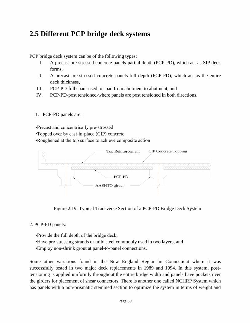
Page 39
Top Reinforcement
AASHTO girder
PCP-PD
CIP Concrete Topping
2.5 Different PCP bridge deck systems
PCP bridge deck system can be of the following types:
I. A precast pre-stressed concrete panels-partial depth (PCP-PD), which act as SIP deck
forms,
II. A precast pre-stressed concrete panels-full depth (PCP-FD), which act as the entire
deck thickness,
III. PCP-PD-full span- used to span from abutment to abutment, and
IV. PCP-PD-post tensioned-where panels are post tensioned in both directions.
1. PCP-PD panels are:
•Precast and concentrically pre-stressed
•Topped over by cast-in-place (CIP) concrete
•Roughened at the top surface to achieve composite action
2. PCP-FD panels:
•Provide the full depth of the bridge deck,
•Have pre-stressing strands or mild steel commonly used in two layers, and
•Employ non-shrink grout at panel-to-panel connections.
Some other variations found in the New England Region in Connecticut where it was
successfully tested in two major deck replacements in 1989 and 1994. In this system, post-
tensioning is applied uniformly throughout the entire bridge width and panels have pockets over
the girders for placement of shear connectors. There is another one called NCHRP System which
has panels with a non-prismatic stemmed section to optimize the system in terms of weight and
Figure 2.19: Typical Transverse Section of a PCP-PD Bridge Deck System

Page 40
reinforcement, and post-tensioning is applied over the girders. Prof. Tadros of the University of
Nebraska developed NUDECK system which was originally a continuous stay-in-place panel
system that evolved later to a full-depth precast, pre-stressed system.
In 1982, a survey of the State Highway Departments by the PCI Bridge Committee showed that
21 states used the panels regularly and another seven states were trying the method through
bidding options or were developing details prior to trial projects(PCI 1987).
According to 1987 survey of PCI, 24 states were using the system (PCI 1987). According to
2003 University of New Hampshire survey, 25 states were using the system (Cook and Latifee,
2003).
2.6 IMPORTANT TERMS
2.6.1 High Performance Concrete High-performance concrete (HPC) is a relatively new term for concrete that conforms to
a set of standards above those of the most common applications, but not limited to
strength. While all high-strength concrete is also high-performance, not all high-
performance concrete is high-strength. Some examples of such standards currently used
in relation to HPC are:
• Ease of placement
• Compaction without segregation
• Early age strength
• Long-term mechanical properties
• Permeability
• Density
• Heat of hydration
• Toughness
• Volume stability
• Long life in severe environments
• Depending on its implementation, environmental.
2.6.2 High Strength Steel The development of pre-stressed concrete was influenced by the invention of high
strength steel. It is an alloy of iron, carbon, manganese and optional materials. The
following elements are made of high strength steel: wires, strands, cables, tendons, bars
etc. The types of high strength steel are follows:
Page 41
• Cold working (cold drawing)
The cold working is done by rolling the bars through a series of dyes. It re-aligns the
Crystals and increases the strength.
• Stress relieving
The stress relieving is done by heating the strand to about 350º C and cooling slowly.
This reduces the plastic deformation of the steel after the onset of yielding.
• Strain tempering for low relaxation
This process is done by heating the strand to about 350º C while it is under tension.
This also improves the stress-strain behavior of the steel by reducing the plastic
deformation after the onset of yielding. In addition, the relaxation is reduced.
2.6.3 Pre-tensioning
Pre-tensioning is accomplished by stressing wires or strands, called tendons, to
predetermined amount by stretching them between two anchorages prior to placing
concrete. The concrete is then placed and tendons become bounded to concrete
throughout their length. After concrete has hardened, the tendons are released by cutting
them at the anchorages. The tendons tend to regain their original length by shortening and
in this process transfer through bond a compressive stress to the concrete. The tendons
are usually stressed by the use of hydraulic jacks. The stress in tendons is maintained
during the placing and curing of concrete by anchoring the ends of the tendons to
abutments that may be as much as 200m apart. The abutments and other formwork used
in this procedure are called pre-stressing bench or bed.
2.6.4 Post-tensioning
In a post-tensioned beam, the tendons are stressed and each end is anchored to the
concrete section after the concrete has been cast and has attained sufficient strength to
safely withstand the pre-stressing force in post-tensioning method, tendons are coated
with grease or a bituminous material to prevent them from becoming bonded to concrete.
Another method used in preventing the tendons from bonding to the concrete during
placing and curing of concrete is to encase the tendon in a flexible metal hose before
placing it in the forms. The metal hose is referred to as sheath or duct and remains in the
structure. After the tendon has been stressed, the void between the tendon and the sheath
is filled with grout. Thus the tendons become bonded to concrete and corrosion of steel is

Page 42
prevented. Post-tension pre- stressing can be done at site. This procedure may become
necessary or desirable in certain cases. For heavy loads and large spans in buildings or
bridges, it may be very difficult to transport a member from pre-casting plant to a job site.
On the other hand, pre-tensioning can be used in pre-cast as well as in cast-in-place
construction. In post-tensioning it is necessary to use some types of device to attach or
anchor the ends of the tendons to the concrete section.
2.7 What is Concrete?
Concrete is a mixture of sand, gravel and/or other aggregates (the matrix), bound together by a
water-based binder, cement. Admixtures (modifying agents) and additives (fine mineral
powders) are sometimes introduced to improve the characteristics of the fresh concrete, of the
mixing process and/or of the final hardened material.
➢ Types of concrete a) Precast
b) Cast in place
2.7.1 What is Precast Concrete?
Precast concrete decks consist of either precast reinforced concrete panels or pre-stressed
concrete panels. These panels can either serve as the final deck surface or as a temporary deck to
allow placement of a final cast-in-place concrete deck. The advantage of a precast concrete deck
is in the acceleration of the construction schedule. Precast panels allow for quicker placement,
which, in principle, speeds up overall bridge construction.
A precast concrete product is a factory-made piece manufactured with concrete and which, later,
together with other pieces, will become part of a larger structure. Precast concrete elements
are prepared, cast and hardened at specially equipped plants with a permanent location.
Once a precast concrete product is produced and all the undertaken quality controls satisfactory,
the unit is stored until delivery. It is then transported for use at another site.

Page 43
Figure 2.20: Precast Concrete
The main advantages of such a process are:
•The intrinsic quality of an industrial product, manufactured in a controlled environment and
with accurate methods;
•Advanced quality control, which goes far beyond the checking of the fresh concrete, can be
introduced. Dimensional accuracy, properties of the hardened concrete and position of
reinforcement can all be checked before inclusion of an element in the final work;
•Factory-made products are independent of weather conditions and can be proceeded
separately from construction work on site.

Page 44
2.7.2 What is Cast-in-Place Concrete? A cast-in-place concrete deck is a thin concrete slab, either using normal reinforcement or pre-
stressing steel, usually between 7 and 12 inches, with reinforcing steel interspersed transversely
and longitudinally throughout the slab. There are several advantages to using a reinforced
concrete deck. One of the major advantages is its relatively low cost. Other advantages are ease
of construction and extensive industry use. Even though cast-in-place concrete decks have
advantages, there are disadvantages using this particular type of deck, such as cracking, rebar
corrosion, and tire noise. A large cost of bridge maintenance is in maintaining the riding surface
(Fu, et al., 2000). Lack of deck crack control can lead to rebar corrosion and increased life cycle
cost, not to mention a poor riding surface for the public.
Cast-in-place concrete is transported in an unhardened state, primarily as ready-mix, and placed
in forms. Ready mixed concrete is proportioned and mixed off the project site. The concrete is
delivered to the site in a truck agitator (often incorrectly called a “cement truck”) but can also be
delivered in a non-agitating truck. Specialized paving equipment may be used to mix and spread
concrete for pavement.
►Uses:
•Most foundations and slabs-on-ground.
•Walls, beams, columns, floors, roofs.
• Large portions of bridges, pavements, and other infrastructure.
Figure 2.21: Cast-in-place Concrete

Page 45
►Why:
Cast-in-place concrete is the material of choice for slab-on-ground and foundations because of its
long-term durability and structural support. It is also used in all types of buildings for either
structural support as beams and columns, as well as for floors, walls, and roofs
►Sustainability:
Ready mixed concrete has many environmental benefits during construction and for the life of
the structure. See associated sustainability solutions and technical briefs (right) for more detail.
►During construction:
i. Waste Minimization:
Concrete is ordered and placed as needed and does not need to be trimmed or cut after
installation. Wash water is frequently recycled using trucks equipped with devices that collect
wash water and return it to the drum where it can be returned to the ready mixed concrete plant
for recycling.
Extra concrete is often returned to the ready-mix plant where it is recycled or used to make
jersey barriers or retaining wall blocks; or it can be washed to recycle the coarse aggregate.
Special set retarding admixtures can be added to return concrete to allow for storage and future
use.
ii. Local:
Materials are usually extracted and manufactured locally.
iii. Recycled content:
Fly ash, slag cement, or silica fume can substitute partially for cement, and recycled aggregates
can replace newly mined gravel.
Page 46
►During the life of the structure:
i. Energy Performance and Thermal Mass: Thermal mass improves energy performance
when appropriately insulated. When 3 inch or more in thickness, concrete forms an air
barrier.
ii. Durable: Concrete stands up to natural disasters, wind-driven rain, moisture damage, and
vermin. Less replacement means reduced resource requirements.
iii. Cool: Using light- or natural-colored material helps reduce the heat island affect.
iv. Low emitting: Concrete has low VOC emission and does not degrade indoor air quality.
v. Recyclable: Concrete is commonly recycled in urban areas into fill and road base
material at the end of service life.
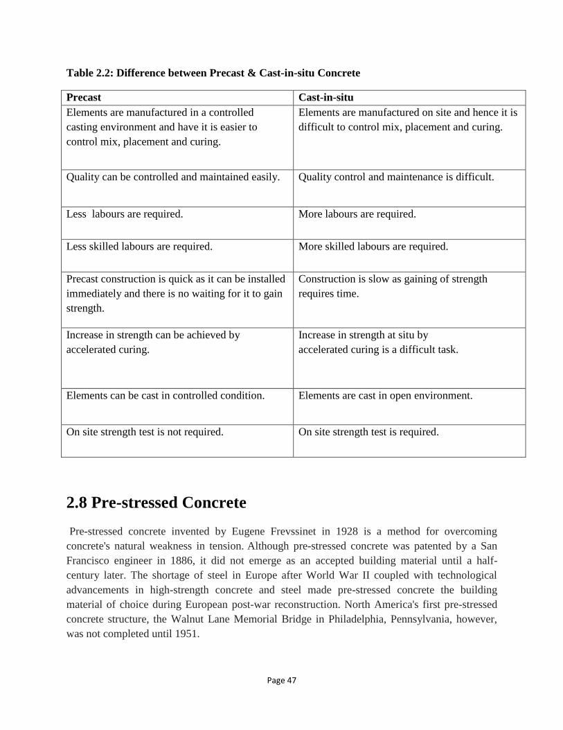
Page 47
Table 2.2: Difference between Precast & Cast-in-situ Concrete
Precast Cast-in-situ
Elements are manufactured in a controlled
casting environment and have it is easier to
control mix, placement and curing.
Elements are manufactured on site and hence it is
difficult to control mix, placement and curing.
Quality can be controlled and maintained easily. Quality control and maintenance is difficult.
Less labours are required. More labours are required.
Less skilled labours are required. More skilled labours are required.
Precast construction is quick as it can be installed
immediately and there is no waiting for it to gain
strength.
Construction is slow as gaining of strength
requires time.
Increase in strength can be achieved by
accelerated curing.
Increase in strength at situ by
accelerated curing is a difficult task.
Elements can be cast in controlled condition. Elements are cast in open environment.
On site strength test is not required. On site strength test is required.
2.8 Pre-stressed Concrete
Pre-stressed concrete invented by Eugene Frevssinet in 1928 is a method for overcoming
concrete's natural weakness in tension. Although pre-stressed concrete was patented by a San
Francisco engineer in 1886, it did not emerge as an accepted building material until a half-
century later. The shortage of steel in Europe after World War II coupled with technological
advancements in high-strength concrete and steel made pre-stressed concrete the building
material of choice during European post-war reconstruction. North America's first pre-stressed
concrete structure, the Walnut Lane Memorial Bridge in Philadelphia, Pennsylvania, however,
was not completed until 1951.

Page 48
In conventional reinforced concrete, the high tensile strength of steel is combined with concrete's
great compressive strength to form a structural material that is strong in both compression and
tension. The principle behind pre-stressed concrete is that compressive stresses induced by high-
strength steel tendons in a concrete member before loads are applied will balance the tensile
stresses imposed in the member during service.
Pre-stressing removes a number of design limitations conventional concrete places on span and
load and permits the building of roofs, floors, bridges, and walls with longer unsupported spans.
This allows architects and engineers to design and build lighter and shallower concrete structures
without sacrificing strength.
Figure 2.22: Pre-stressed Concrete
The principle behind pre-stressing is applied when a row of books is moved from place to place.
Instead of stacking the books vertically and carrying them, the books may be moved in a
horizontal position by applying pressure to the books at the end of the row. When sufficient
pressure is applied, compressive stresses are induced throughout the entire row, and the whole
row can be lifted and carried horizontally at once.
Pre-stressed concrete has experienced greatest growth in the field of commercial buildings. For
buildings such as shopping centers, pre-stressed concrete is an ideal choice because it provides
the span length necessary for flexibility and alteration of the internal structure. Pre-stressed
concrete is also used in school auditoriums, gymnasiums, and cafeterias because of its acoustical
properties and its ability to provide long, open spaces. One of the most widespread uses of pre-
stressed concrete is parking garages.

Page 49
2.8.1 Advantages of Pre-stressed Concrete
1. The size or dimensions of structural members are reduced, which may increase the
clearances or reduce storey heights.
2. It permits the use of large spans (greater than 30 m) with shallow members, even when
heavy load are encountered.
3. In addition to general advantages, such as excellent fire resistance, low maintenance costs,
elegance, high corrosion-resistance, adaptability etc, the pre-stressed concrete is found to
sustain the effects of impact or shock and vibrations.
4. Because of smaller loads due to smaller dimensions being used, there is considerable saving
cost of supporting members and foundations.
5. The pre-stressing technique has eliminated the weakness of concrete in tension and hence
crack free members of structure are obtained.
6. Because of better material (i.e. controlled concrete and high tension steel) being used and
nullifying the effect of dead loads, smaller deflections are caused.
2.8.2 Disadvantages of Pre-stressed Concrete The following are among the advantages of using pre-stressed concrete.
1. The unit cost of high strength materials being used is higher.
2. Extra initial cost is incurred due to use of pre-stressing equipment and its installation.
3. Extra labour cost for pre-stressing is also there.
4. Pre-stressing is uneconomical for short spans and light loads.
2.9 Pre-tensioning
In pre-tensioning, the steel is stretched before the concrete is placed. High-strength steel tendons
are placed between two abutments and stretched to 70 to 80 percent of their ultimate strength.
Concrete is poured into molds around the tendons and allowed to cure. Once the concrete reaches
the required strength, the stretching forces are released. As the steel reacts to regain its original
length, the tensile stresses are translated into a compressive stress in the concrete. Typical
products for pre-tensioned concrete are roof slabs, piles, poles, bridge girders, wall panels, and
railroad ties.
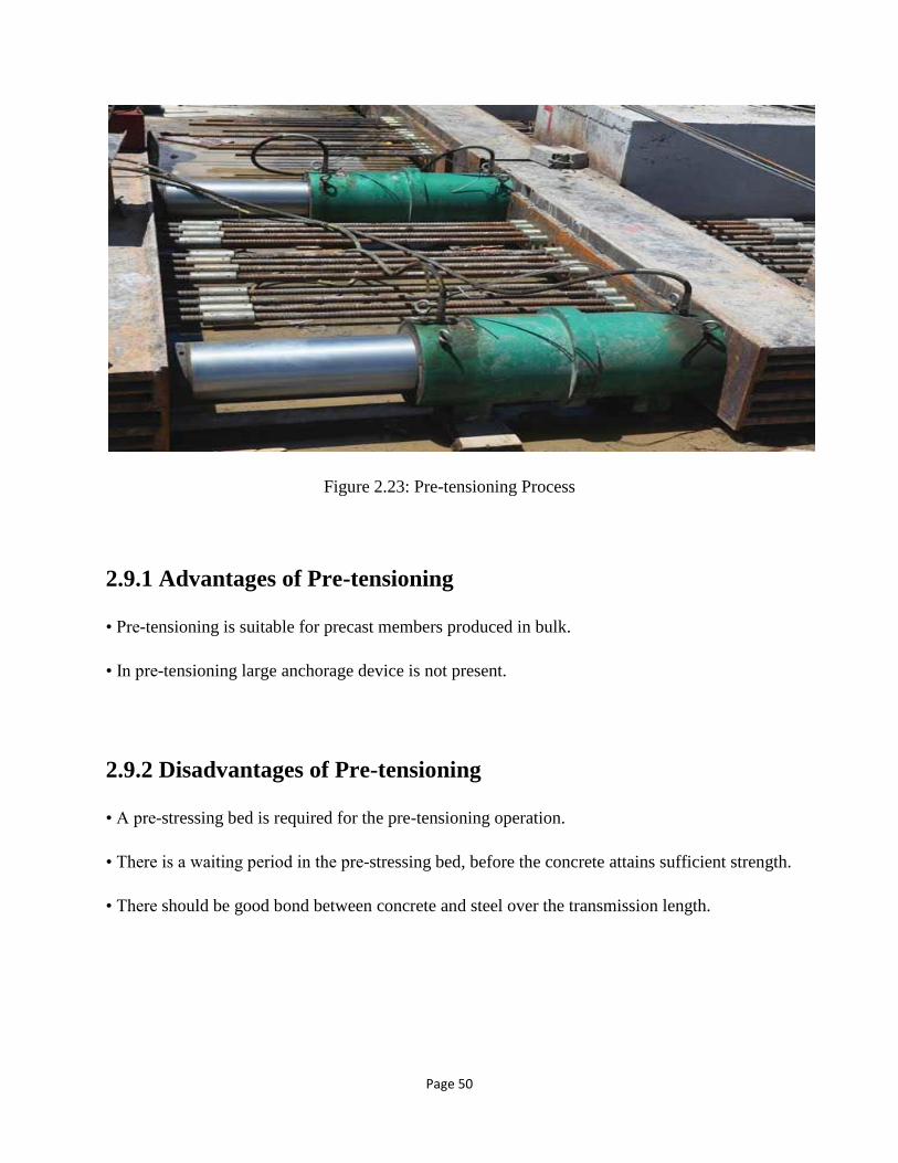
Page 50
Figure 2.23: Pre-tensioning Process
2.9.1 Advantages of Pre-tensioning
• Pre-tensioning is suitable for precast members produced in bulk.
• In pre-tensioning large anchorage device is not present.
2.9.2 Disadvantages of Pre-tensioning
• A pre-stressing bed is required for the pre-tensioning operation.
• There is a waiting period in the pre-stressing bed, before the concrete attains sufficient strength.
• There should be good bond between concrete and steel over the transmission length.

Page 51
2.10 Post-tensioning
In post-tensioning, the steel is stretched after the concrete hardens. Concrete is cast around, but
not in contact with un-stretched steel. In many cases, ducts are formed in concrete unit using
thin walled steel forms. Once the concrete has hardened to the required strength, the steel
tendons are inserted and stretched against the ends of the unit and anchored off externally,
placing the concrete into compression. Post-tensioned concrete is used for cast-in-place concrete
and for bridges, large girders, floor slabs, shells, roofs, and pavements.
Figure 2.24: Post-tensioning Process
2.10.1 Advantages of Post-tensioning
1. Reduced cost: Post tension slabs are excellent ways to construct stronger structures at an
affordable price. There are many structures like parking garages as well as stadiums, since
they are required to hold much more weight than average buildings; this slab becomes a
viable option.

Page 52
2. Flexibility in design: The designs made with this slab are sleek, require lesser space and
give way to dynamic contours. All this makes them ideal for the expression of creativity in
the building design.
3. Lesser usage of materials: Since the post tension slab is thin, the materials used with it
are also lesser. Be it the thin beams, walls or supporting pillar of buildings, this compact
concrete slab does not need bulky materials.
4. Durability: Being a very strong substitute of the normal concrete, it lasts longer.
2.10.2 Disadvantages of Post-tensioning
1. Corrosive: Since there are a number of tendons and wires spread inside the post tension
slab, it can result in corrosion. But largely, this tendency to corrode depends on the quality of
the material used.
2. Complexity of work: The post tension slab can be made only by skillful professionals.
The local workers may not have the necessary skills required to prepare this complex slab.
3. Poor workmanship can lead to accidents: The main problem with using post tension
slab is that if care is not taken while making it, it can lead to future mishaps. Many a times,
ignorant workers do not fill the gaps of the tendons and wiring completely. These gaps cause
corrosion of the wires which may break untimely, leading to some untoward events
2.11 Full Depth Bridge Deck Panel
Precast deck panels are capable of improving durability and quality of the deck thorough
casting in a controlled environment. Full-depth precast deck panels are usually developed for
accelerating bridge construction. Use of these panels to bridge construction has gained wide
acceptance because they can offer several advantages such as rapid construction, minimal
onsite formwork and scaffolding, reduced labor and structural costs, and improved quality and
durability. In addition, these bridge decks may require lower maintenance and life-cycle costs.
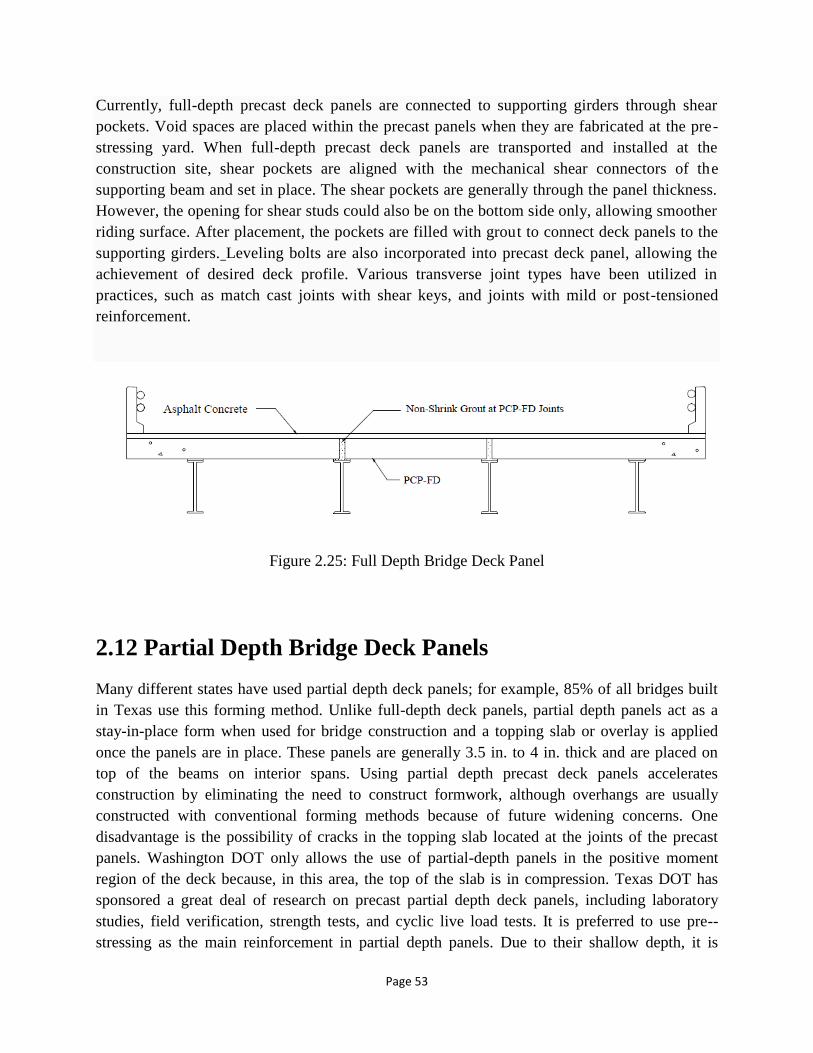
Page 53
Currently, full-depth precast deck panels are connected to supporting girders through shear
pockets. Void spaces are placed within the precast panels when they are fabricated at the pre-
stressing yard. When full-depth precast deck panels are transported and installed at the
construction site, shear pockets are aligned with the mechanical shear connectors of the
supporting beam and set in place. The shear pockets are generally through the panel thickness.
However, the opening for shear studs could also be on the bottom side only, allowing smoother
riding surface. After placement, the pockets are filled with grout to connect deck panels to the
supporting girders. Leveling bolts are also incorporated into precast deck panel, allowing the
achievement of desired deck profile. Various transverse joint types have been utilized in
practices, such as match cast joints with shear keys, and joints with mild or post-tensioned
reinforcement.
Figure 2.25: Full Depth Bridge Deck Panel
2.12 Partial Depth Bridge Deck Panels
Many different states have used partial depth deck panels; for example, 85% of all bridges built
in Texas use this forming method. Unlike full-depth deck panels, partial depth panels act as a
stay-in-place form when used for bridge construction and a topping slab or overlay is applied
once the panels are in place. These panels are generally 3.5 in. to 4 in. thick and are placed on
top of the beams on interior spans. Using partial depth precast deck panels accelerates
construction by eliminating the need to construct formwork, although overhangs are usually
constructed with conventional forming methods because of future widening concerns. One
disadvantage is the possibility of cracks in the topping slab located at the joints of the precast
panels. Washington DOT only allows the use of partial-depth panels in the positive moment
region of the deck because, in this area, the top of the slab is in compression. Texas DOT has
sponsored a great deal of research on precast partial depth deck panels, including laboratory
studies, field verification, strength tests, and cyclic live load tests. It is preferred to use pre--
stressing as the main reinforcement in partial depth panels. Due to their shallow depth, it is
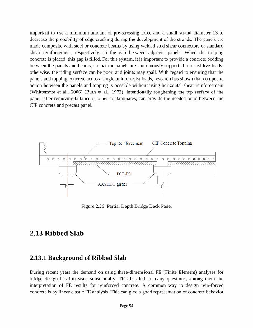
Page 54
important to use a minimum amount of pre-stressing force and a small strand diameter 13 to
decrease the probability of edge cracking during the development of the strands. The panels are
made composite with steel or concrete beams by using welded stud shear connectors or standard
shear reinforcement, respectively, in the gap between adjacent panels. When the topping
concrete is placed, this gap is filled. For this system, it is important to provide a concrete bedding
between the panels and beams, so that the panels are continuously supported to resist live loads;
otherwise, the riding surface can be poor, and joints may spall. With regard to ensuring that the
panels and topping concrete act as a single unit to resist loads, research has shown that composite
action between the panels and topping is possible without using horizontal shear reinforcement
(Whittemore et al., 2006) (Buth et al., 1972); intentionally roughening the top surface of the
panel, after removing laitance or other contaminates, can provide the needed bond between the
CIP concrete and precast panel.
Figure 2.26: Partial Depth Bridge Deck Panel
2.13 Ribbed Slab
2.13.1 Background of Ribbed Slab
During recent years the demand on using three-dimensional FE (Finite Element) analyses for
bridge design has increased substantially. This has led to many questions, among them the
interpretation of FE results for reinforced concrete. A common way to design rein-forced
concrete is by linear elastic FE analysis. This can give a good representation of concrete behavior
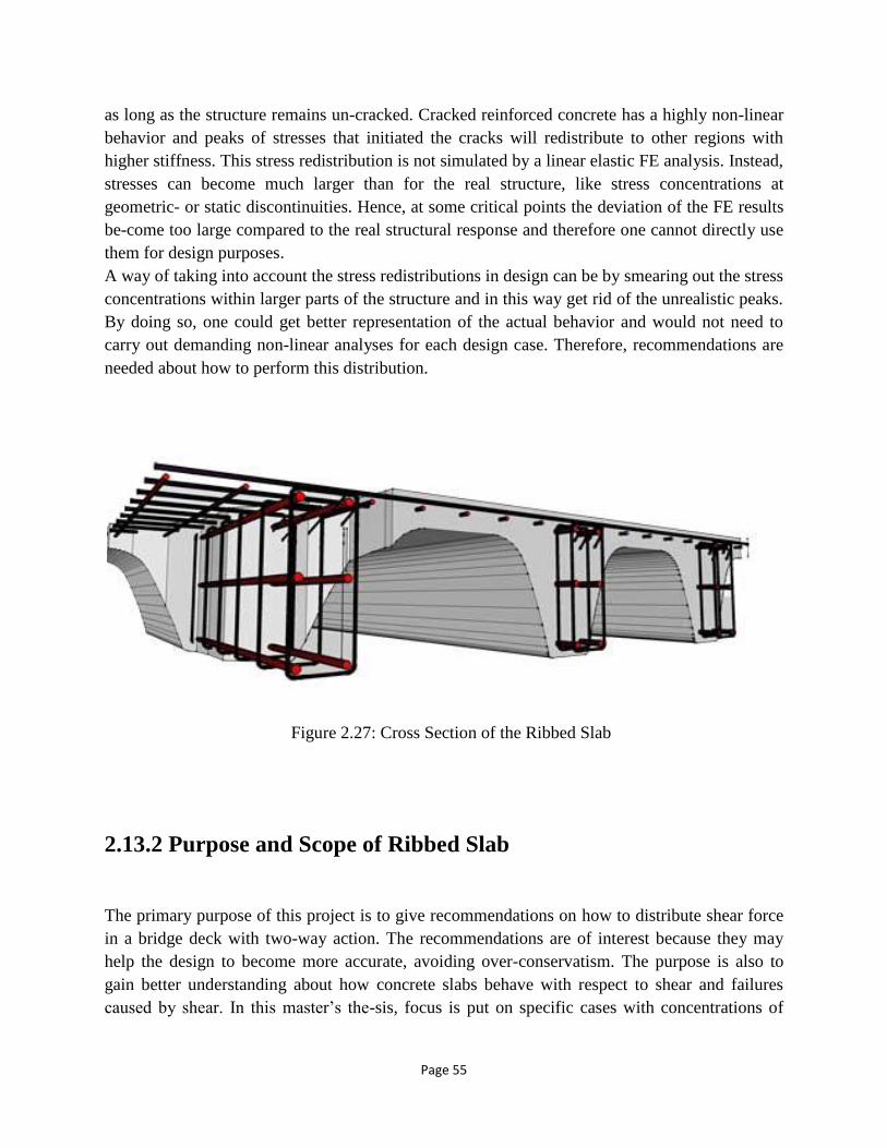
Page 55
as long as the structure remains un-cracked. Cracked reinforced concrete has a highly non-linear
behavior and peaks of stresses that initiated the cracks will redistribute to other regions with
higher stiffness. This stress redistribution is not simulated by a linear elastic FE analysis. Instead,
stresses can become much larger than for the real structure, like stress concentrations at
geometric- or static discontinuities. Hence, at some critical points the deviation of the FE results
be-come too large compared to the real structural response and therefore one cannot directly use
them for design purposes.
A way of taking into account the stress redistributions in design can be by smearing out the stress
concentrations within larger parts of the structure and in this way get rid of the unrealistic peaks.
By doing so, one could get better representation of the actual behavior and would not need to
carry out demanding non-linear analyses for each design case. Therefore, recommendations are
needed about how to perform this distribution.
2.13.2 Purpose and Scope of Ribbed Slab
The primary purpose of this project is to give recommendations on how to distribute shear force
in a bridge deck with two-way action. The recommendations are of interest because they may
help the design to become more accurate, avoiding over-conservatism. The purpose is also to
gain better understanding about how concrete slabs behave with respect to shear and failures
caused by shear. In this master’s the-sis, focus is put on specific cases with concentrations of
Figure 2.27: Cross Section of the Ribbed Slab
Page 56
shear force, for instance concentrated loads on bridge decks. The recommendations should
however be general and applicable to all cases with concrete slabs.
2.14 Necessity of Shrinkage Reinforcement
Hardening of concrete always associate with change in volume resulting shrinkage stresses. It is
advisable to minimize such shrinkage by using concrete with the smallest possible amounts of
water and cement compatible with other requirements, like strength and workability, and by
thorough moist-curing of sufficient during. But a certain degree of shrinkage is usually
unavoidable irrespective of what precautions are taken.
In case of slab having moderate dimensions freely rested on its supports can contract to
compensate the shortening of its length produced by shrinkage. But in normal case, slabs and
other members are joined rigidly to other parts of the structure and restricted to contract,
producing shrinkage stress. In outdoor structures like bridges, a decrease in temperature relative
to that at which the slab was poured subjected to similar effect of shrinkage.
2.15 CODE Requirements
Minimum Shrinkage and temperature reinforcement normal to primary flexural reinforcement is
required for structural floor and roof slabs (not slabs on ground) where the flexural reinforcement
extends in one direction only.
2.15.1 Placement of Reinforcement
In slabs, provided with reinforcement provided for bending moments has the desirable effect of
reducing shrinkage and distribution cracks. However, as contraction take place equally in all
directions, it is necessary to provide special reinforcement for shrinkage and temperature
contraction in the direction perpendicular to the main reinforcement. This added steel is known
as temperature or shrinkage reinforcement.

Page 57
Reinforcement for shrinkage and temperature stresses normal to the principal reinforcement
should be provided in a structural slab which the principal reinforcement extends in one direction
only. ACI code 7. 12. 2 specifies the minimum ratios of reinforcement area to gross concrete
area (i.e. based on the total depth of the slab) shown in Table below, but in no case may such
reinforcing bars be placed farther apart than 5 times the slab thickness or more than 18 in. In no
case is the reinforcement ratio to be less than 0.0014.
Table 2.3: Minimum Ratio of Temperature and Shrinkage Reinforcement
The steel required by the ACI code for shrinkage and temperature crack control also represent
the minimum permissible reinforcement in the span direction of one-way slabs; the usual
minimum for flexural steel do not apply.
Finally, temperature and shrinkage reinforcement plays an important role for temperature and
moisture change. It should be done according to the code.
Page 58
Chapter- 03
DESIGN OF BD DECK-1
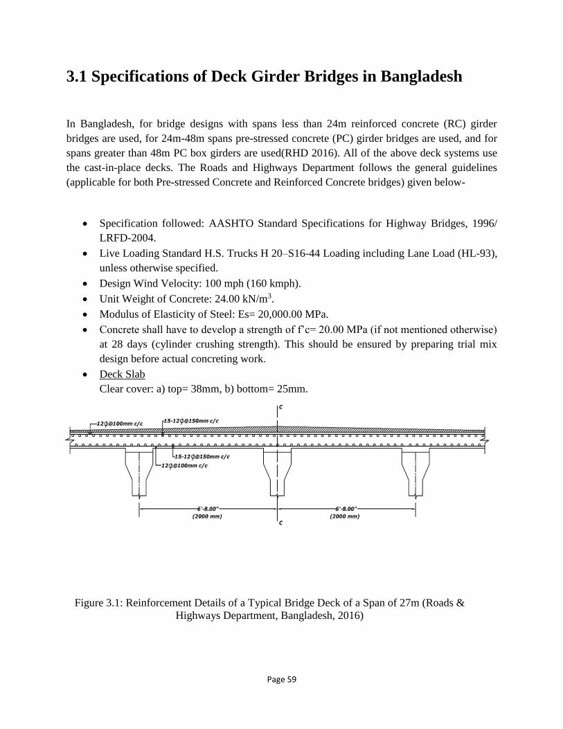
Page 59
3.1 Specifications of Deck Girder Bridges in Bangladesh
In Bangladesh, for bridge designs with spans less than 24m reinforced concrete (RC) girder
bridges are used, for 24m-48m spans pre-stressed concrete (PC) girder bridges are used, and for
spans greater than 48m PC box girders are used(RHD 2016). All of the above deck systems use
the cast-in-place decks. The Roads and Highways Department follows the general guidelines
(applicable for both Pre-stressed Concrete and Reinforced Concrete bridges) given below-
• Specification followed: AASHTO Standard Specifications for Highway Bridges, 1996/
LRFD-2004.
• Live Loading Standard H.S. Trucks H 20–S16-44 Loading including Lane Load (HL-93),
unless otherwise specified.
• Design Wind Velocity: 100 mph (160 kmph).
• Unit Weight of Concrete: 24.00 kN/m3.
• Modulus of Elasticity of Steel: Es= 20,000.00 MPa.
• Concrete shall have to develop a strength of f’c= 20.00 MPa (if not mentioned otherwise)
at 28 days (cylinder crushing strength). This should be ensured by preparing trial mix
design before actual concreting work.
• Deck Slab
Clear cover: a) top= 38mm, b) bottom= 25mm.
Figure 3.1: Reinforcement Details of a Typical Bridge Deck of a Span of 27m (Roads &
Highways Department, Bangladesh, 2016)

Page 60
Figure 3.2: Reinforcement Details of a Typical Bridge Deck of a Span of 21m ( Roads &
Highways Department, Bangladesh, 2016)
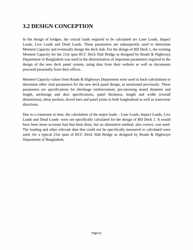
Page 61
3.2 DESIGN CONCEPTION
In the design of bridges, the crucial loads required to be calculated are Lane Loads, Impact
Loads, Live Loads and Dead Loads. These parameters are subsequently used to determine
Moment Capacity and eventually design the deck slab. For the design of BD Deck 1, the existing
Moment Capacity for the 21m span RCC Deck Slab Bridge as designed by Roads & Highways
Department of Bangladesh was used in the determination of important parameters required in the
design of the new deck panel system, using data from their website as well as documents
procured personally from their offices.
Moment Capacity values from Roads & Highways Department were used in back-calculations to
determine other vital parameters for the new deck panel design, as mentioned previously. These
parameters are specifications for shrinkage reinforcement, pre-stressing strand diameter and
length, anchorage and duct specifications, panel thickness, length and width (overall
dimensions), shear pockets, dowel bars and panel joints in both longitudinal as well as transverse
directions.
Due to a constraint in time, the calculation of the major loads – Lane Loads, Impact Loads, Live
Loads and Dead Loads- were not specifically calculated for the design of BD Deck 1. It would
have been more accurate had that been done, but an alternative method, also correct, was used.
The loading and other relevant data that could not be specifically measured or calculated were
used, for a typical 21m span of RCC Deck Slab Bridge as designed by Roads & Highways
Department of Bangladesh.

Page 62
3.3 Design Calculation (For Exterior and Interior Deck
Panel)
Moment Capacity from the Drawings of Roads & Highways Department (typical 21m
span)
Main Reinforcement used= 16mm dia. @ 137mm C/C
Area of steel= (0.31*12”)/5” = 0.744 in2 /ft [controls]
Asmin= .0018*12*8= 0.1728 in2/ft
a= Asfy/.85bf’c = (.744*60)/(.85*12*3) = 1.46 in
As= 12M/[.9*60*(7-.73)]= 0.744
So, M= 21 k-ft
Reinforcement for BD-Deck-1 Proposed Design Matching RHD bridge deck Moment
Capacity
Moment= 21 k-ft
As= (21*12”)/.9*270*(7-.33) = 0.155 in2/ft
a= .155*270/.85*6*12 = 0.684 in
Provide two 3/8 in dia. pre-stressing strands,
Area of pre-stressing steel= 0.085*2 = 0.17 in2
Distribution reinforcement,
Asmin= 0.002bh = .002*12*8 = 0.192 in2
Having used 10mm bars, the spacing was found to be= 0.121*12/0.192 = 7 in C/C.
(Data for this calculation was taken from The Roads & Highways Department of Bangladesh,
2016.)
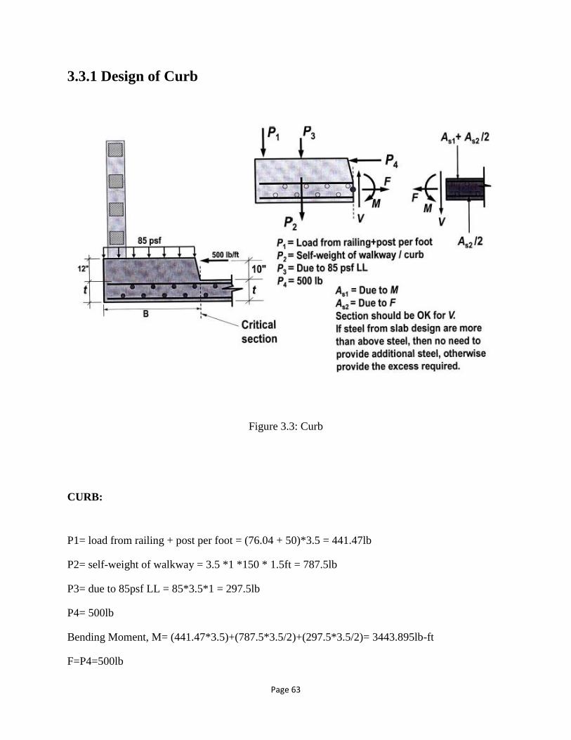
Page 63
3.3.1 Design of Curb
Figure 3.3: Curb
CURB:
P1= load from railing + post per foot = (76.04 + 50)*3.5 = 441.47lb
P2= self-weight of walkway = 3.5 *1 *150 * 1.5ft = 787.5lb
P3= due to 85psf LL = 85*3.5*1 = 297.5lb
P4= 500lb
Bending Moment, M= (441.47*3.5)+(787.5*3.5/2)+(297.5*3.5/2)= 3443.895lb-ft
F=P4=500lb

Page 64
Curb thickness, t+12= 18in
drequired=√3443.895∗12
.9∗.016∗12∗60000∗(1−.59∗.016∗60000
3500)
= 4.8in <dprovided
Steel Area due to M, As1= M/Øfy(d-a/2)
= 3443.895/{.9*60000*(18-.077/2)} = .00355 in2
[a=1in, As=.046 in2/ft
a=.077in, As= .045in2/ft]
Therefore, a=Asfy/.85fc’b
a=.077in and As=.045in2
Spacing= .11*12/.045=29.3 in
Use #3 bars @ 29in c/c.
For accidental impact loads in the horizontal direction,
Assuming impact load, P4 or F=500lb
AS F= F/(Øfy) = 500/(.4*60000) = .009 in2/ft
Spacing= .11*12/.009 = 146.7 in > 2t (= 2*5in = 10in)
Use #3 bar @ 10in c/c.
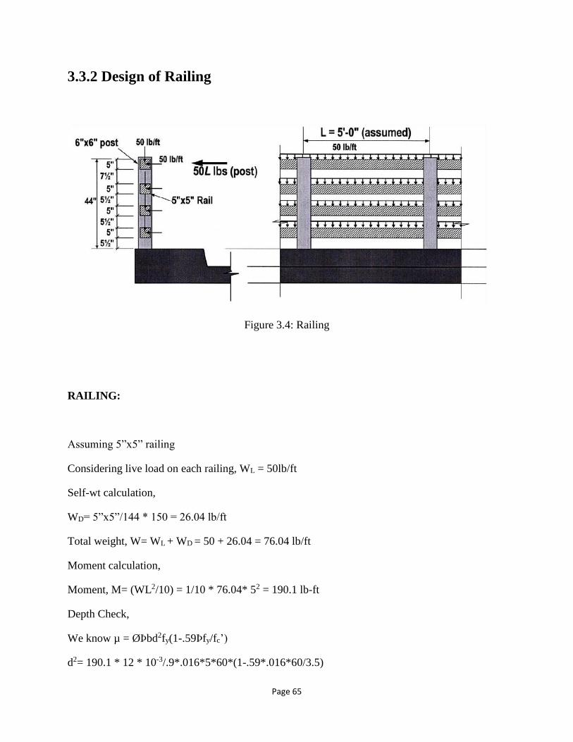
Page 65
3.3.2 Design of Railing
Figure 3.4: Railing
RAILING:
Assuming 5”x5” railing
Considering live load on each railing, WL = 50lb/ft
Self-wt calculation,
WD= 5”x5”/144 * 150 = 26.04 lb/ft
Total weight, W= WL + WD = 50 + 26.04 = 76.04 lb/ft
Moment calculation,
Moment, M= (WL2/10) = 1/10 * 76.04* 52 = 190.1 lb-ft
Depth Check,
We know µ = ØÞbd2fy(1-.59Þfy/fc’)
d2= 190.1 * 12 * 10-3/.9*.016*5*60*(1-.59*.016*60/3.5)

Page 66
Therefore, d= 0.794in<dassumed (=2.5in)
Area of Steel, As= M/Øfy(d-a/2)
= 190.1/{.9*60000*(2.5-.07/2)} = .001428 in2
[a=1in, As=.0211 in2/ft
a=.09in, As= .017in2/ft
a=.07in, As=.017in2/ft]
Therefore, a=Asfy/.85fc’b
a=.07in and As=.02in2
Asmin=(200/fy)*bwd = (200/60000) *5* 2.5 = .04 in2 (controls)
Use #3 bars.
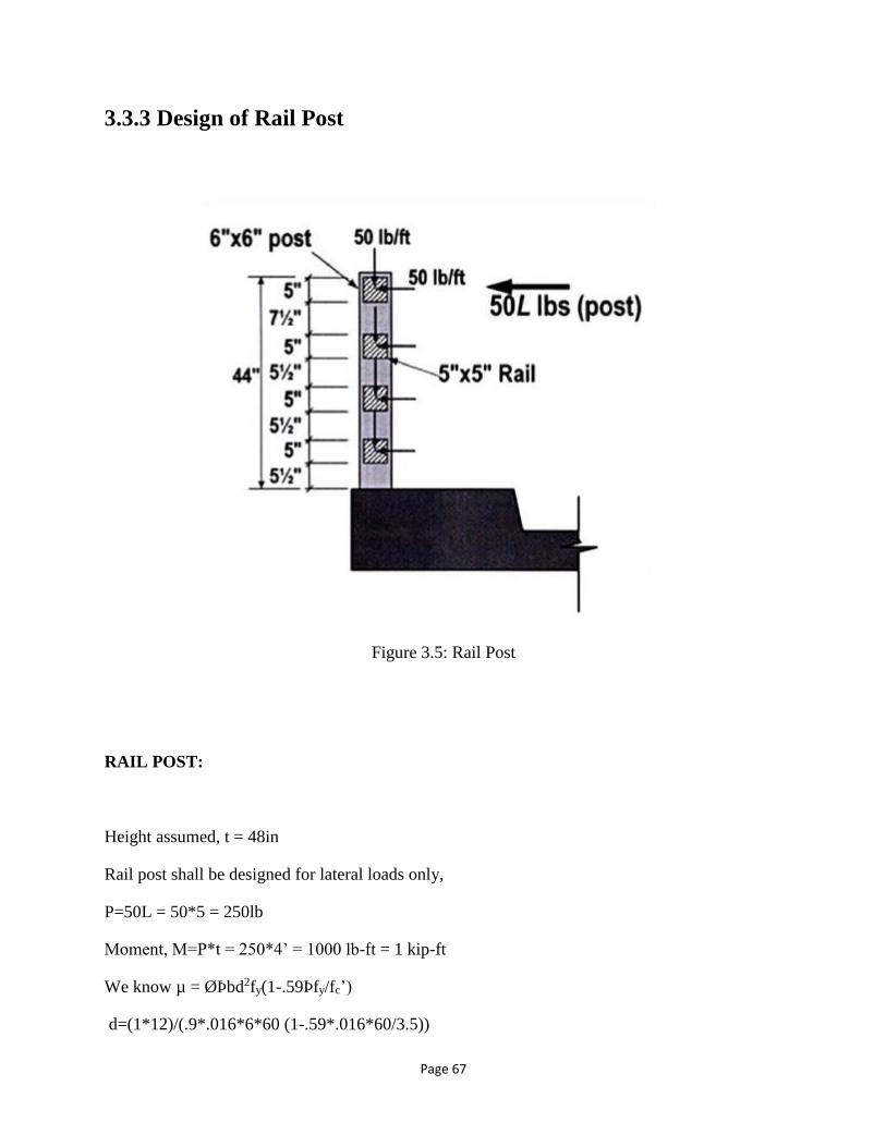
Page 67
3.3.3 Design of Rail Post
Figure 3.5: Rail Post
RAIL POST:
Height assumed, t = 48in
Rail post shall be designed for lateral loads only,
P=50L = 50*5 = 250lb
Moment, M=P*t = 250*4’ = 1000 lb-ft = 1 kip-ft
We know µ = ØÞbd2fy(1-.59Þfy/fc’)
d=(1*12)/(.9*.016*6*60 (1-.59*.016*60/3.5))

Page 68
Therefore, d=1.7in <dprovided(=3.5in)
Area of Steel, As= M/Øfy(d-a/2)
= 1000/{.9*60000*(3.5-.22/2)} = .00546 in2
[a=1in, As=.074 in2/ft
a=.25in, As= .066in2/ft
a=.22in, As=.066in2/ft]
Therefore, a=Asfy/.85fc’b
a=.22in and As=.066in2
Asmin=(200/fy)*bwd = (200/60000) *6* 3.5 = .07 in2 (controls)
Use #3 bars.

Page 69
3.4 BD DECK 1 DETAILS
The proposed design consists of full-depth precast, pre-stressed concrete panels. The panel depth
is 8 inches with ribs- where the upper depth of 4.5 inches is the continuous solid and the lower
depth of 3.5 inches is the rib depth. The ribs are 2 feet C/C and they span from girder to girder.
In the proposed design, the panel width is 7 feet. Higher strength concrete of 6000 psi (42 MPa)
and higher strength steel of 270,000 psi (1862 MPa ) are considered for pre-tensioning. The pre-
stressing strands are of 3/8 inches diameter. The transverse dimension of the panels will depend
on the girders’ C/C distance.
The shrinkage reinforcements are 10mm bars provided at the top. The strength of the distribution
reinforcement is taken as 60,000 psi (414 Mpa). The crown can be achieved by the base support
under the panels.
The deck panels will be joined by using dowel bars, as shown in the figure 3.7. These dowel bars
will be placed within the shear pockets and then filled by non-shrink grout. At the top, a 0.5 inch
gap is provided between two panels, which are filled with bitumen filler. This will allow for
concrete expansion and contraction. If needed, bitumen overlay for a smoother surface, with
approximately 3 inches at the crown and 1 inch near the curbs can be provided.
The minute details of BD Deck 1 are still being developed. The following figures show sections
of the proposed design. This deck design has taken into consideration the existing capacity of the
cast-in-place (CIP) bridge decks as employed by Roads and Highways Department of
Bangladesh.

Page 70
Figure 3.6: Typical Cross Section of BD Deck 1
Figure 3.7: Contraction Joints with Dowel Bar
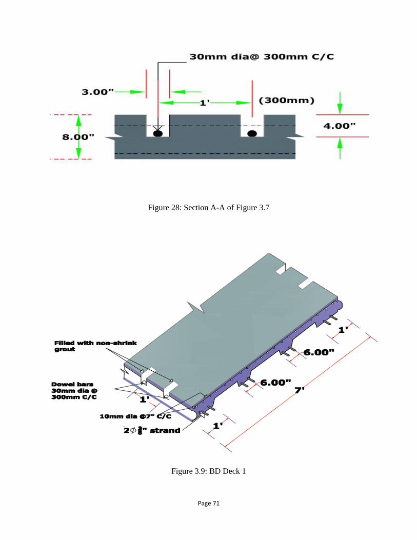
Page 71
Figure 28: Section A-A of Figure 3.7
Figure 3.9: BD Deck 1
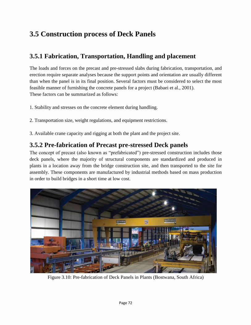
Page 72
3.5 Construction process of Deck Panels
3.5.1 Fabrication, Transportation, Handling and placement
The loads and forces on the precast and pre-stressed slabs during fabrication, transportation, and
erection require separate analyses because the support points and orientation are usually different
than when the panel is in its final position. Several factors must be considered to select the most
feasible manner of furnishing the concrete panels for a project (Babaei et al., 2001).
These factors can be summarized as follows:
1. Stability and stresses on the concrete element during handling.
2. Transportation size, weight regulations, and equipment restrictions.
3. Available crane capacity and rigging at both the plant and the project site.
3.5.2 Pre-fabrication of Precast pre-stressed Deck panels The concept of precast (also known as “prefabricated”) pre-stressed construction includes those
deck panels, where the majority of structural components are standardized and produced in
plants in a location away from the bridge construction site, and then transported to the site for
assembly. These components are manufactured by industrial methods based on mass production
in order to build bridges in a short time at low cost.
Figure 3.10: Pre-fabrication of Deck Panels in Plants (Bostwana, South Africa)
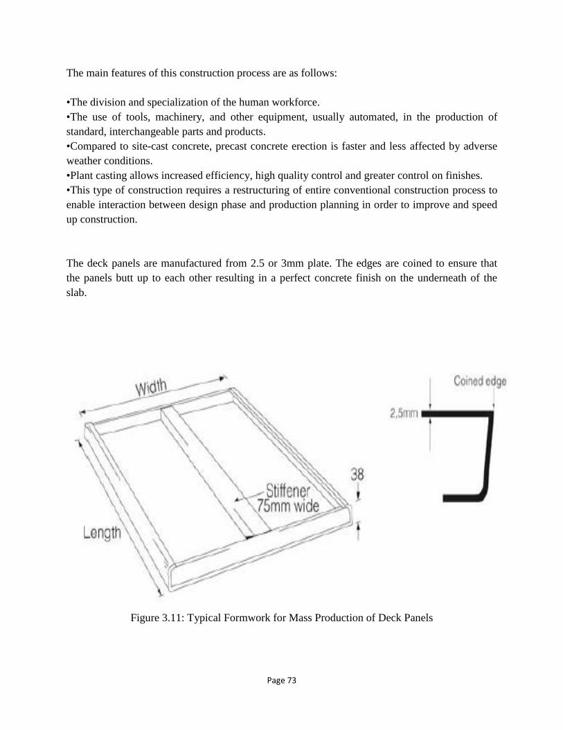
Page 73
The main features of this construction process are as follows:
•The division and specialization of the human workforce.
•The use of tools, machinery, and other equipment, usually automated, in the production of
standard, interchangeable parts and products.
•Compared to site-cast concrete, precast concrete erection is faster and less affected by adverse
weather conditions.
•Plant casting allows increased efficiency, high quality control and greater control on finishes.
•This type of construction requires a restructuring of entire conventional construction process to
enable interaction between design phase and production planning in order to improve and speed
up construction.
The deck panels are manufactured from 2.5 or 3mm plate. The edges are coined to ensure that
the panels butt up to each other resulting in a perfect concrete finish on the underneath of the
slab.
Figure 3.11: Typical Formwork for Mass Production of Deck Panels
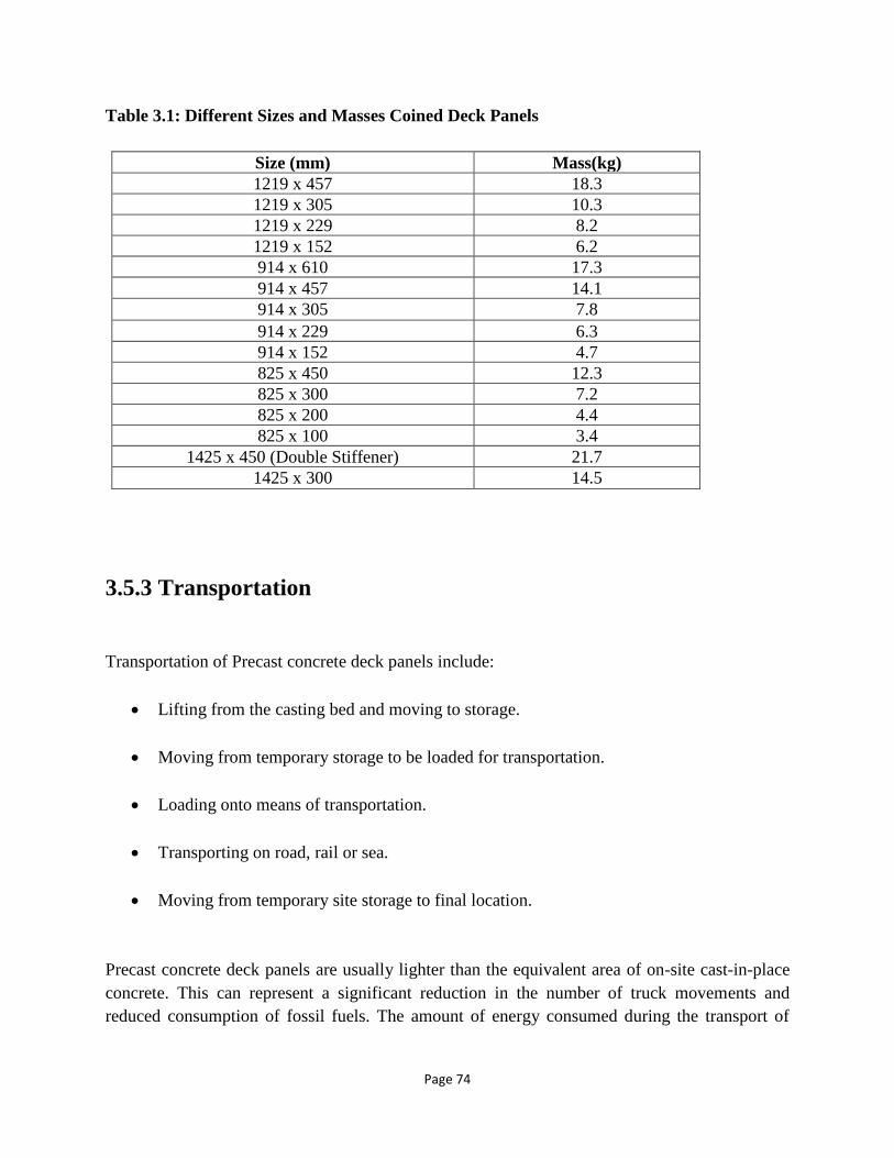
Page 74
Table 3.1: Different Sizes and Masses Coined Deck Panels
Size (mm) Mass(kg)
1219 x 457 18.3
1219 x 305 10.3
1219 x 229 8.2
1219 x 152 6.2
914 x 610 17.3
914 x 457 14.1
914 x 305 7.8
914 x 229 6.3
914 x 152 4.7
825 x 450 12.3
825 x 300 7.2
825 x 200 4.4
825 x 100 3.4
1425 x 450 (Double Stiffener) 21.7
1425 x 300 14.5
3.5.3 Transportation
Transportation of Precast concrete deck panels include:
• Lifting from the casting bed and moving to storage.
• Moving from temporary storage to be loaded for transportation.
• Loading onto means of transportation.
• Transporting on road, rail or sea.
• Moving from temporary site storage to final location.
Precast concrete deck panels are usually lighter than the equivalent area of on-site cast-in-place
concrete. This can represent a significant reduction in the number of truck movements and
reduced consumption of fossil fuels. The amount of energy consumed during the transport of

Page 75
precast elements is about 0.00114 MJ/kg/km. This represents 5% to 10% of the total energy
consumption during manufacturing of precast concrete elements.
Figure 3.12: Transportation of Deck Panels
3.5.4 Handling
Position of the crane must be considered, since capacity is a function of reach. Improper jobsite
handling and storage, of the relatively thin pre-stressed sections required for modular bridge deck
construction or replacement, can lead to dimensional instability, cracking, or warping that will
adversely impact the panels’ suitability for placement in the new superstructure. The contractor
should be directed by representatives from the pre-stress supplier in regard to proper lifting
techniques as well as blocking configurations necessary if jobsite storage will be required prior
to slab installation. If jobsite storage is required, the site should be carefully chosen and set up
so that varying weather conditions do not lead to settlement problems. Once the initial dunnage
bedways are set up, periodic elevation checks should be performed for verification that no
settlement problems have occurred. Special attention must be given to irregularly shaped pieces
or any section that might have a post-casting induced crown.
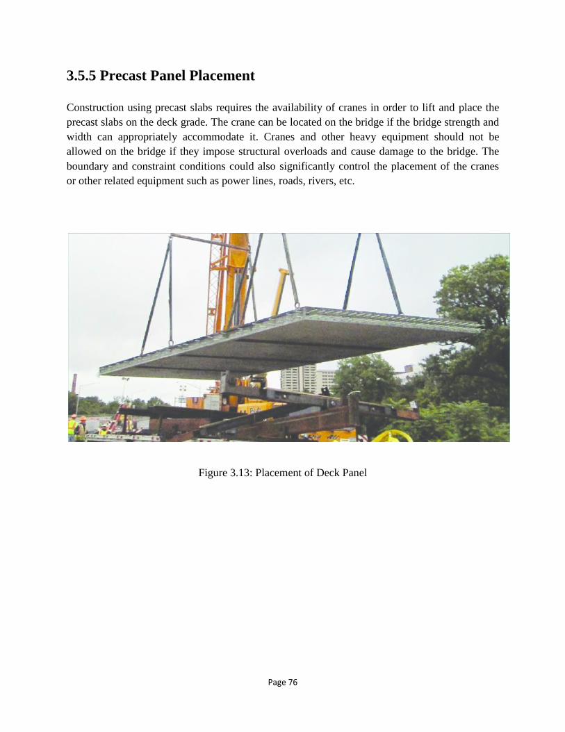
Page 76
3.5.5 Precast Panel Placement
Construction using precast slabs requires the availability of cranes in order to lift and place the
precast slabs on the deck grade. The crane can be located on the bridge if the bridge strength and
width can appropriately accommodate it. Cranes and other heavy equipment should not be
allowed on the bridge if they impose structural overloads and cause damage to the bridge. The
boundary and constraint conditions could also significantly control the placement of the cranes
or other related equipment such as power lines, roads, rivers, etc.
Figure 3.13: Placement of Deck Panel

Page 77
3.6 Steps of Deck Placement
Figure 3.14: Lifting & Placement of a Panel on Supporting Girders
► Step 1: A singular panel is lifted using crane and chords attached to the panel.
► Step 2: The panel is placed on top of the supporting girders, to in this case.
Step 1 Step 2

Page 78
Figure 3.15: Placement of Subsequent Panels
► Step 3: The chords are detached from the panel.
► Step 4: The other panels are placed in a similar fashion.
Step 3 Step 4
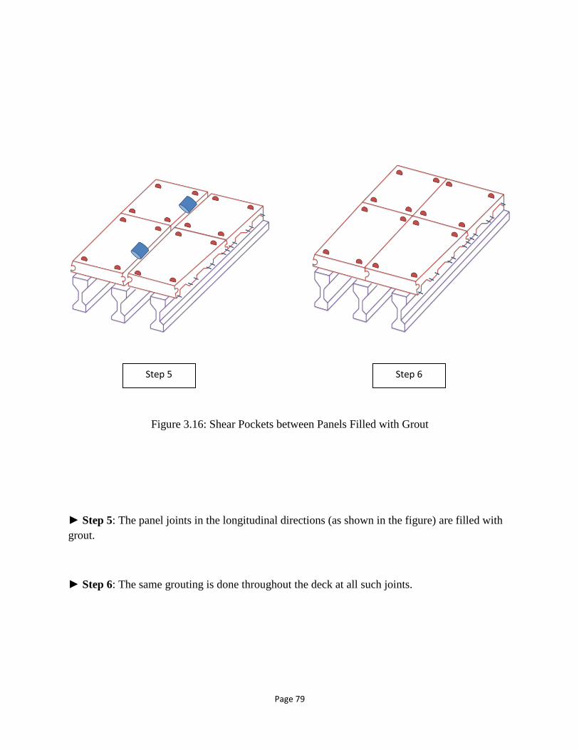
Page 79
Figure 3.16: Shear Pockets between Panels Filled with Grout
► Step 5: The panel joints in the longitudinal directions (as shown in the figure) are filled with
grout.
► Step 6: The same grouting is done throughout the deck at all such joints.
Step 5 Step 6

Page 80
Figure 3.17: Construction of Deck Completed
► Step 7: The final step is the bitumen layer a top the panels now jointed. The deck is hence
completed.
Step 7
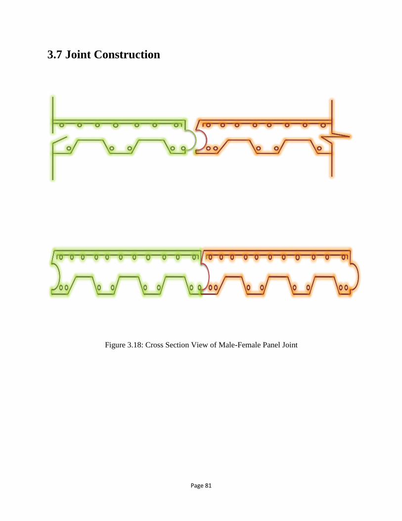
Page 81
3.7 Joint Construction
Figure 3.18: Cross Section View of Male-Female Panel Joint

Page 82
Chapter- 04
ECONOMIC ANALYSIS

Page 83
4.1 Area Reduction
Area = 8/12 * 7 = 4.6 ft2
Hollow portion,
Area = ((13/12 * 2 + 16/12) * 3.5/12) + (.5 * (1/12) * (3.5/12)) * 6
= 1.02 + 0.07 ft2
=1.09 ft2
Reduced Area = (1.09/4.6) * 100%
= 23.76%
4.2 Volume Reduction
Volume = (2* 2.13* 0.203) m = 0.864 m3
Area of hollow portion = 1.09 ft2 = 0.1012643m2
Reduced volume = (0.10126 * 2) m3, where 2m = girder to girder distance
= 0.20252 m3
Volume of shear pocket = (.0762* 0.1016* 0.3) m3 = .00232 m3
Total volume = (0.864 - 0.20252 - .00232) m3 = 0.66 m3
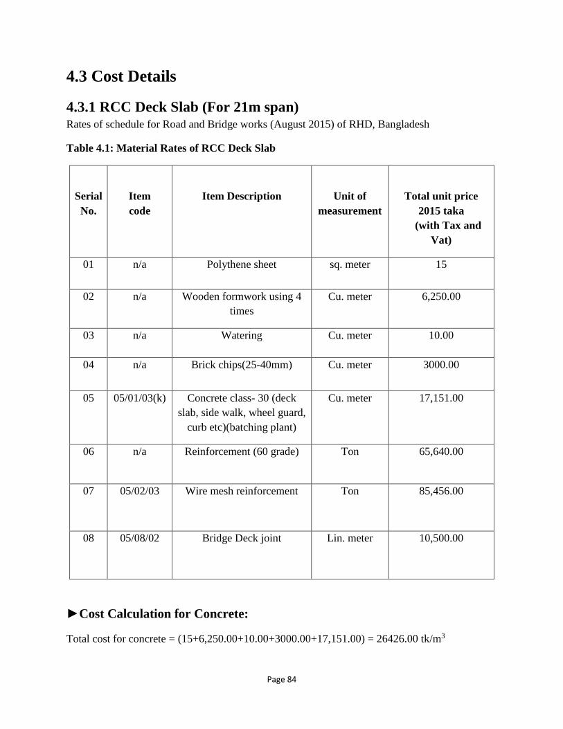
Page 84
4.3 Cost Details
4.3.1 RCC Deck Slab (For 21m span) Rates of schedule for Road and Bridge works (August 2015) of RHD, Bangladesh
Table 4.1: Material Rates of RCC Deck Slab
Serial
No.
Item
code
Item Description
Unit of
measurement
Total unit price
2015 taka
(with Tax and
Vat)
01 n/a Polythene sheet sq. meter 15
02 n/a Wooden formwork using 4
times
Cu. meter 6,250.00
03 n/a Watering Cu. meter 10.00
04 n/a Brick chips(25-40mm) Cu. meter 3000.00
05 05/01/03(k) Concrete class- 30 (deck
slab, side walk, wheel guard,
curb etc)(batching plant)
Cu. meter 17,151.00
06 n/a Reinforcement (60 grade) Ton 65,640.00
07 05/02/03 Wire mesh reinforcement Ton 85,456.00
08
05/08/02
Bridge Deck joint
Lin. meter
10,500.00
►Cost Calculation for Concrete:
Total cost for concrete = (15+6,250.00+10.00+3000.00+17,151.00) = 26426.00 tk/m3

Page 85
Figure 4.1: Typical deck Slab Detailing of 21m Span (Drawing from Roads & Highway
Department)
►Cost Calculation for Reinforcement:
•Along Transverse Direction:
1. Main Reinforcement = 16Ø @ 275mm c/c
2. Cranked Bar (with girder) = 10Ø @ 275mm c/c
3. Extra Bar = 16Ø @ 137mm c/c
4. Alt. Cranked = 16Ø @ 137mm c/c
•Along Longitudinal Direction:
1. Distribution Reinforcement = 12Ø @ 275mm c/c
So, for Distribution Reinforcement 12Ø @ 275mm c/c at longitudinal direction,
Cross-sectional width = 10250mm
No of Bars required = (10250/275) = 37.27 ⸗ 38nos

Page 86
10250m (cross-sectional width) is provided with = 38 bars
Therefore, 1000mm or 1 meter is provided with = ((38*1000)/10250) = 3.70 ⸗ 4nos bars of 21m.
Therefore, total length of 4 bars = (4*21) = 84 meter
For Main Reinforcement 16Ø @ 275mm c/c at transverse direction,
Length = 21000mm
No of Bars required = (21000/275) = 76.36 ⸗ 77nos
21000 is provided with = 77nos bars
Therefore, 1000mm or 1 meter is provided with = ((77*1000)/21000) = 3.63 ⸗ 4nos bars of
10.25m.
Therefore, total length of 4 bars = (4*10.25) = 41 meter
Similarly,
For Cranked Bars: 4 bars of 1.25m length are required.
For Alt. Cranked &Extra Tops: 16 bars of 1.25m length are required.
Therefore, total length of cranked bar = (4*1.25) = 5 meter
Total length of cranked bar = (8*1.25) = 10 meter
Total length of cranked bar = (8*1.25) = 10 meter
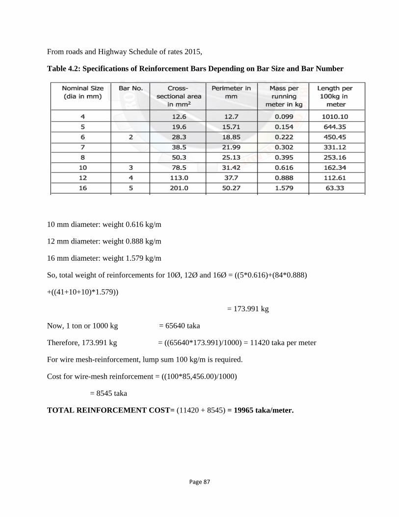
Page 87
From roads and Highway Schedule of rates 2015,
Table 4.2: Specifications of Reinforcement Bars Depending on Bar Size and Bar Number
10 mm diameter: weight 0.616 kg/m
12 mm diameter: weight 0.888 kg/m
16 mm diameter: weight 1.579 kg/m
So, total weight of reinforcements for 10Ø, 12Ø and 16Ø = ((5*0.616)+(84*0.888)
+((41+10+10)*1.579))
= 173.991 kg
Now, 1 ton or 1000 kg = 65640 taka
Therefore, 173.991 kg = ((65640*173.991)/1000) = 11420 taka per meter
For wire mesh-reinforcement, lump sum 100 kg/m is required.
Cost for wire-mesh reinforcement = ((100*85,456.00)/1000)
= 8545 taka
TOTAL REINFORCEMENT COST= (11420 + 8545) = 19965 taka/meter.
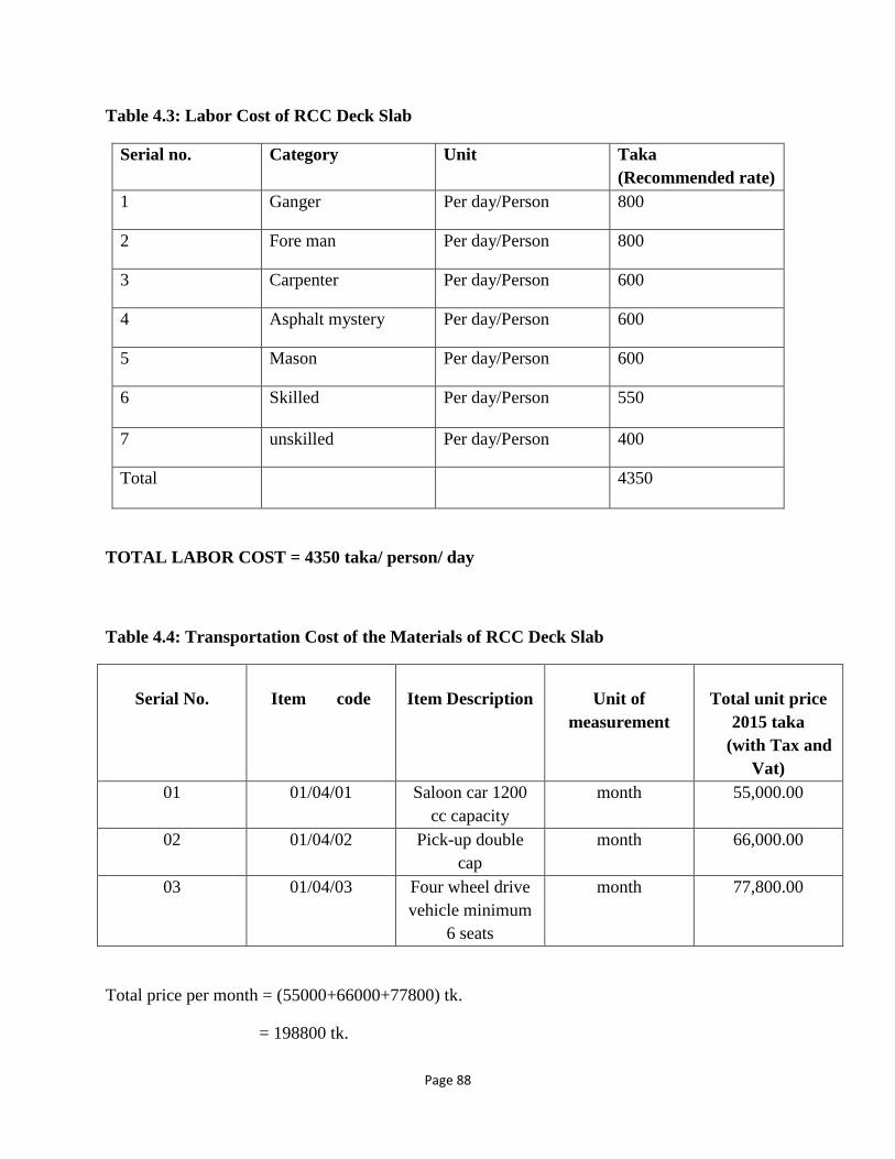
Page 88
Table 4.3: Labor Cost of RCC Deck Slab
Serial no. Category Unit Taka
(Recommended rate)
1 Ganger Per day/Person 800
2 Fore man Per day/Person 800
3 Carpenter Per day/Person 600
4 Asphalt mystery Per day/Person 600
5 Mason Per day/Person 600
6 Skilled Per day/Person 550
7 unskilled Per day/Person 400
Total 4350
TOTAL LABOR COST = 4350 taka/ person/ day
Table 4.4: Transportation Cost of the Materials of RCC Deck Slab
Serial No.
Item code
Item Description
Unit of
measurement
Total unit price
2015 taka
(with Tax and
Vat)
01 01/04/01 Saloon car 1200
cc capacity
month 55,000.00
02 01/04/02 Pick-up double
cap
month 66,000.00
03 01/04/03 Four wheel drive
vehicle minimum
6 seats
month 77,800.00
Total price per month = (55000+66000+77800) tk.
= 198800 tk.
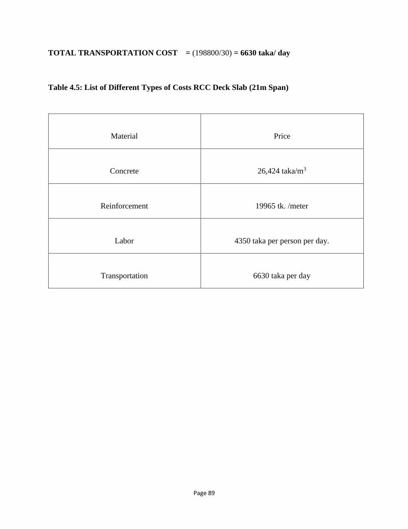
Page 89
TOTAL TRANSPORTATION COST = (198800/30) = 6630 taka/ day
Table 4.5: List of Different Types of Costs RCC Deck Slab (21m Span)
Material
Price
Concrete
26,424 taka/m3
Reinforcement
19965 tk. /meter
Labor
4350 taka per person per day.
Transportation
6630 taka per day
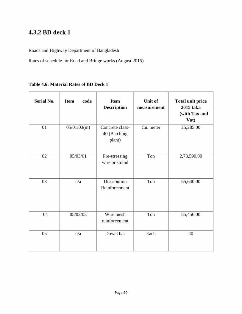
Page 90
4.3.2 BD deck 1
Roads and Highway Department of Bangladesh
Rates of schedule for Road and Bridge works (August 2015)
Table 4.6: Material Rates of BD Deck 1
Serial No.
Item code
Item
Description
Unit of
measurement
Total unit price
2015 taka
(with Tax and
Vat)
01 05/01/03(m) Concrete class-
40 (Batching
plant)
Cu. meter 25,285.00
02 05/03/01 Pre-stressing
wire or strand
Ton 2,73,590.00
03 n/a Distribution
Reinforcement
Ton 65,640.00
04 05/02/03 Wire mesh
reinforcement
Ton 85,456.00
05 n/a Dowel bar Each 40

Page 91
►Cost of High Strength Concrete:
Total concrete cost = 25,285.00 tk.
Calculation of Cost of Distribution reinforcement and Pre-stressing Strand:
For Distribution Reinforcement
From the Drawing of BD deck 1, used 10mmØ @ 7” c/c
= 10mmØ @ 177.8mm c/c in both directions.
For individual Deck panel,
In Longitudinal direction = 7’ =2134.15mm
No. of Bars required = (2134.15/177.8) = 12nos
Therefore, Bars per 1000mm or 1meter = ((12*1000)/2134.15) = 5.62 = 6 bars of 2m length
= 12 meter
In Transverse direction = 2m(c/c distance of girders) = 2000mm
No. of Bars required = (2000/177.8) = 11.248nos = 12nos
Therefore, Bars per 1000mm or 1meter = ((12*1000)/2000) = 6 bars of 2.13m
= 12.78 meter
So, total weight of reinforcements for 10Ø = ((12+12.78)*0.616) = 15.26 kg/meter
Now, 1ton or 1000 kg. = 65640 tk.
Therefore, 7.392 kg. = ((65640*15.26)/1000) = 1001.96 taka per meter
For wire mesh-reinforcement, lump sum 5 kg/meter is required.
Cost for wire-mesh reinforcement = ((10*85,456.00)/1000)
= 854.56 tk.
Total cost for reinforcement = (1001.96+854.56) = 1856.52 tk. /meter
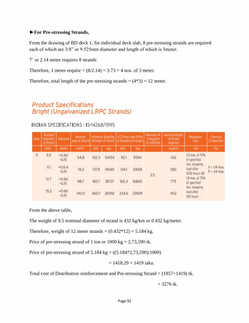
Page 92
►For Pre-stressing Strands,
From the drawing of BD deck 1, for individual deck slab, 8 pre-stressing strands are required
each of which are 3/8” or 9.525mm diameter and length of which is 3meter.
7’ or 2.14 meter requires 8 strands
Therefore, 1 meter require = (8/2.14) = 3.73 = 4 nos. of 3 meter.
Therefore, total length of the pre-stressing strands = (4*3) = 12 meter.
From the above table,
The weight of 9.5 nominal diameter of strand is 432 kg/km or 0.432 kg/meter.
Therefore, weight of 12 meter strands = (0.432*12) = 5.184 kg.
Price of pre-stressing strand of 1 ton or 1000 kg = 2,73,590 tk.
Price of pre-stressing strand of 5.184 kg = ((5.184*2,73,590)/1000)
= 1418.29 = 1419 taka.
Total cost of Distribution reinforcement and Pre-stressing Strand = (1857+1419) tk.
= 3276 tk.

Page 93
Table 4.7: Labor Cost of BD Deck 1
Serial no. Category Unit Taka
(Recommended rate)
1 Rebar Fabrication Per day/Person 500
2 Shuttering Per day/Person 500
3 De-shuttering Per day/Person 500
4 Segment lifting Per day/Person 500
Total 2000
Total labor cost = 2000 taka.
Table 4.8: Transportation Cost of BD Deck 1
Serial No.
Item code
Item Description
Unit of
measurement
Total unit price
2015 taka
(with Tax and
Vat)
01 01/04/03 Four wheel drive
vehicle minimum
6 seats
month 77,800.00
Total price per month = 77800 tk.
Total price per day = (77800/30) = 2594 tk.

Page 94
Table 4.9: Summary of Costs for BD Deck 1
MATERIAL
PRICE
Concrete
25,285 taka/m3
Reinforcement
3276 taka/meter
Labor
2000 taka/ person/ day
Transportation
2594 taka/ day
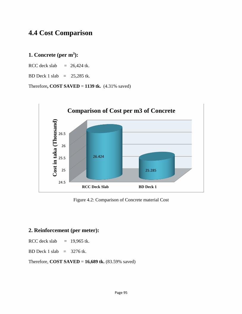
Page 95
4.4 Cost Comparison
1. Concrete (per m3):
RCC deck slab = 26,424 tk.
BD Deck 1 slab = 25,285 tk.
Therefore, COST SAVED = 1139 tk. (4.31% saved)
Figure 4.2: Comparison of Concrete material Cost
2. Reinforcement (per meter):
RCC deck slab = 19,965 tk.
BD Deck 1 slab = 3276 tk.
Therefore, COST SAVED = 16,689 tk. (83.59% saved)
24.5
25
25.5
26
26.5
RCC Deck Slab BD Deck 1
26.424
25.285
Co
st i
n t
ak
a (
Th
ou
san
d)
Comparison of Cost per m3 of Concrete

Page 96
Figure 4.3: Comparison of Reinforcement Cost
3. Labor (per person/day):
RCC deck slab = 4,350 tk.
BD Deck 1 slab = 2,000 tk.
Therefore, COST SAVED = 2,350 tk. (54.02% saved)
0
5
10
15
20
RCC Deck Slab BD Deck 1
19.965
3.276
Co
st i
n t
ak
a (
Th
ou
san
d)
Comparison of Cost of Reinforcement per
linear meter
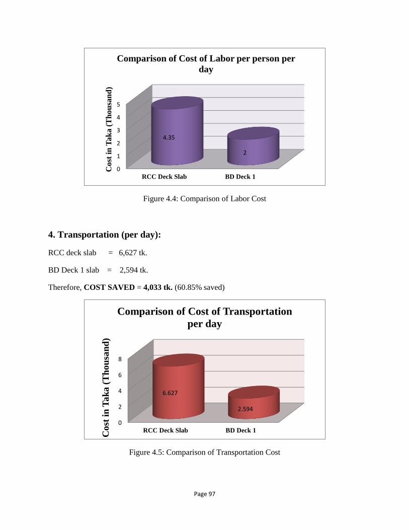
Page 97
Figure 4.4: Comparison of Labor Cost
4. Transportation (per day):
RCC deck slab = 6,627 tk.
BD Deck 1 slab = 2,594 tk.
Therefore, COST SAVED = 4,033 tk. (60.85% saved)
Figure 4.5: Comparison of Transportation Cost
0
1
2
3
4
5
RCC Deck Slab BD Deck 1
4.35
2
Cost
in
Tak
a (
Th
ou
san
d)
Comparison of Cost of Labor per person per
day
0
2
4
6
8
RCC Deck Slab BD Deck 1
6.627
2.594
Co
st i
n T
ak
a (
Th
ou
san
d)
Comparison of Cost of Transportation
per day
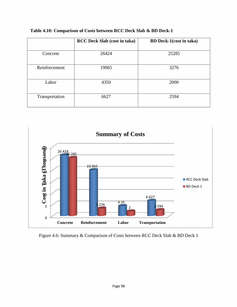
Page 98
Table 4.10: Comparison of Costs between RCC Deck Slab & BD Deck-1
RCC Deck Slab (cost in taka) BD Deck-1(cost in taka)
Concrete 26424 25285
Reinforcement 19965 3276
Labor 4350 2000
Transportation 6627 2594
Figure 4.6: Summary & Comparison of Costs between RCC Deck Slab & BD Deck 1
0
5
10
15
20
25
30
Concrete Reinforcement Labor Transportation
26.424
19.965
4.35
6.627
25.285
3.2762 2.594
Co
st i
n T
ak
a (
Th
ou
san
d)
Summary of Costs
RCC Deck Slab
BD Deck 1
Page 99
4.5 Comparison of Costs between RCC Deck Slab & BD
Deck 1 (per km)
4.5.1 BD Deck 1 (Background Calculation)
[Data obtained from “Unity Engineering & Construction”
Address: 28 Tipu Sultan Road, Wari, Dhaka-1100]
According to the data obtained, span of pre-stressed girder is 24m. Cost of 24m span is 80 to 90
lac taka (that are already used in Mogbazar-Mouchak Flyover Project). Here for calculation we
have taken the average value of 85 lac taka for 24m span.
1. MATERIAL COST OF 1 BOX GIRDER
We know that the Span = 24m, with 8 boxes per span.
Length of 1 box = 24m/8 = 3m
Width of 1 box= 7.5m
Depth of 1 box = 2m
So, Volume of 1 box= 3*7.5*2 = 45m3
The solid portion of the total volume is 40%. Therefore volume of 1 box is =
45*0.4=18m3
Therefore, Material Cost= 85 lac/8 = 10.6 lac taka
2. LABOR COST OF 1 BOX GIRDER
Labor required per box:
Rebar Fabrication – 24 persons
Shuttering – 24 persons
De-shuttering – 8persons
Segment Lifting – 4 persons
Total labors needed = 60
Rate = 500tk/ head/ day
No. of days needed to make 1 box girder = 80 days
Labor Cost = 60*500*80 = 24 lac taka

Page 100
3. TRANSPORTATION COST OF 1 BOX GIRDER
Project duration = 24 months
Trailer rate = 10 lac per month
High-Capacity Crane rate = 14 lac per month
Considering, only 1 day is required to transport 1 box girder from plant to site, and 8
boxes are carried at the same time each trip-
Transportation Cost = 24lacs/ (30*8) = 0.1 lac taka
4. FORM WORK COST OF 1 BOX GIRDER
Rate = 300 ton mold at 1 lac per ton
Where, 1 mold can make 329 boxes
So, total cost of 1 mold = 300*1 = 300 lac taka
Formwork Cost = 300/329 = 0.91 lac taka
Therefore, the Total Cost of 3m Span or 1 Box Girder is = 10.6 + 24 + 0.1 + 0.91
= 35.6 lac taka
For a volume of 18m3 (box girder) cost is = 35.6 lac
For a volume of 0.66m3 (BD Deck 1 panel) cost is = (35.6*0.66)/ 18 = 1.30 lac taka
Therefore, for 3m span of BD Deck 1, the cost is = 1.30 lac
for 1m span of BD Deck 1, the cost is = 1.30/3 = 0.435 lac
for 1000m span of BD Deck 1, the cost is = 435 lac taka = 43.5 million taka per km
Cost of BD Deck 1 = 43.5 million taka per km
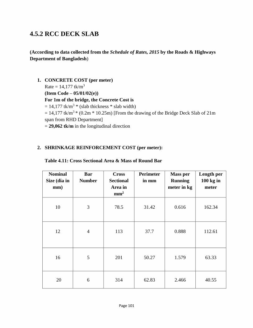
Page 101
4.5.2 RCC DECK SLAB
(According to data collected from the Schedule of Rates, 2015 by the Roads & Highways
Department of Bangladesh)
1. CONCRETE COST (per meter)
Rate = 14,177 tk/m3
(Item Code – 05/01/02(e))
For 1m of the bridge, the Concrete Cost is
= 14,177 tk/m3 * (slab thickness * slab width)
= 14,177 tk/m3 * (0.2m * 10.25m) [From the drawing of the Bridge Deck Slab of 21m
span from RHD Department]
= 29,062 tk/m in the longitudinal direction
2. SHRINKAGE REINFORCEMENT COST (per meter):
Table 4.11: Cross Sectional Area & Mass of Round Bar
Nominal
Size (dia in
mm)
Bar
Number
Cross
Sectional
Area in
mm2
Perimeter
in mm
Mass per
Running
meter in kg
Length per
100 kg in
meter
10
3
78.5
31.42
0.616
162.34
12
4
113
37.7
0.888
112.61
16
5
201
50.27
1.579
63.33
20
6
314
62.83
2.466
40.55
Page 102
Rate (grade 60 steel) = 65,640 tk/ton
[From unit Rate of Materials (Annexure-II)]
No. of rods-
• Top : 46 rods of 12mm dia.
• Bottom : 6 rods of 20mm dia.
36 rods of 12mm dia.
For 1m bridge, the weights of rods are-
• 12mm: 0.888kg * [((46+36)/10.2)*21] = 0.149 tons
• 20mm: 2.466kg * (6/10.2) *21 = 0.0304 tons
For 1m of the bridge, the Cost of Shrinkage Reinforcement is
= (0.149 +0.0304) * 65,640 = 11,776 taka/m
3. MAIN REINFORCEMENT COST (per meter)
Rate (grade 60 steel) = 65,640 tk/ton
For 16mm bars
• At top, every 275 mm there is = 1 rod
Therefore total number of bars = 21000/275 = 77 rods
Number of rods per meter = 77/21 = 4 rods
Length of total rods = 4* 10.25 = 41 m
Considering alternate cranked bars at bottom, there are 77 more rods at top.
Number of cranked bars per meter = 77/21 = 4 rods
Length of cranked bars = 4*(450+350+450)/1000 = 5 m
Therefore total length of bars = 41+5 = 46 m
• At bottom, every 137 mm there is = 1 rod
Therefore total number of bars = 21000/137 = 154 rods
Number of rods per meter = 154/21 = 8 rods
Length of total rods = 8* 10.25 = 82 m
Considering alternate cranked bars at bottom, there are 8 more rods at top.
Length of cranked bars = 8*(450+350+450)/1000 = 10 m
Therefore total length of bars = 82+10 = 92 m
Therefore total length of 16mm bar = (46+92) = 138 m
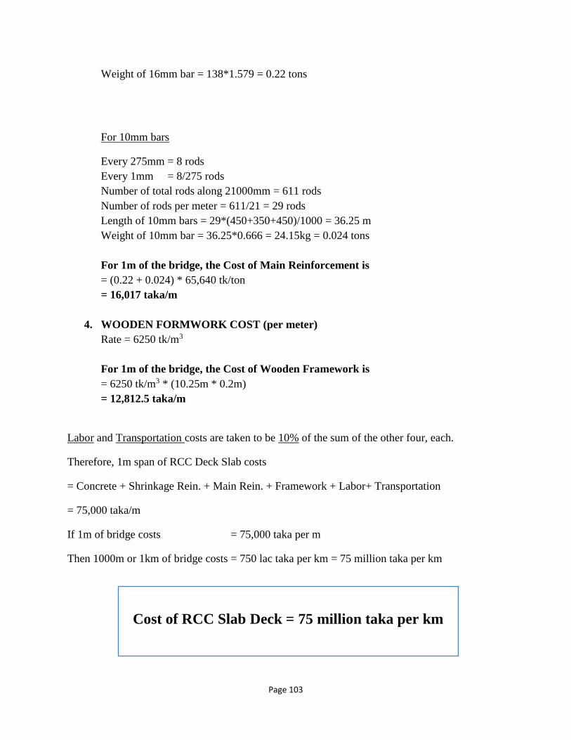
Page 103
Weight of 16mm bar = 138*1.579 = 0.22 tons
For 10mm bars
Every 275mm = 8 rods
Every 1mm = 8/275 rods
Number of total rods along 21000mm = 611 rods
Number of rods per meter = 611/21 = 29 rods
Length of 10mm bars = 29*(450+350+450)/1000 = 36.25 m
Weight of 10mm bar = 36.25*0.666 = 24.15kg = 0.024 tons
For 1m of the bridge, the Cost of Main Reinforcement is
= (0.22 + 0.024) * 65,640 tk/ton
= 16,017 taka/m
4. WOODEN FORMWORK COST (per meter)
Rate = 6250 tk/m3
For 1m of the bridge, the Cost of Wooden Framework is
= 6250 tk/m3 * (10.25m * 0.2m)
= 12,812.5 taka/m
Labor and Transportation costs are taken to be 10% of the sum of the other four, each.
Therefore, 1m span of RCC Deck Slab costs
= Concrete + Shrinkage Rein. + Main Rein. + Framework + Labor+ Transportation
= 75,000 taka/m
If 1m of bridge costs = 75,000 taka per m
Then 1000m or 1km of bridge costs = 750 lac taka per km = 75 million taka per km
Cost of RCC Slab Deck = 75 million taka per km

Page 104
Table 4.12: Comparison of Costs between RCC Deck Slab & BD Deck 1 (per km)
RCC Deck Slab
BD Deck 1
75 million taka per km
43.5 million taka per km
Figure 4.7: Comparison of Costs between RCC Deck Slab & BD Deck 1 (per km)
From the above calculation the difference of cost between RCC Deck Slab & BD Deck 1 per km
is (75-43.5) = 31.5 million taka. Therefore 31.5 million taka is saved per km.
So, BD Deck 1 is more cost effective than the traditional RCC Deck Slab.
0
20
40
60
80
RCC Deck Slab BD Deck 1
75
43.5
Co
st i
n t
ak
a (
mil
lio
n)
Comparison pf Costs between RCC Deck slab &
BD Deck 1 (per km)

Page 105
Chapter- 05
CONCLUSION &
RECOMMENDATION
Page 106
5.1 CONCLUSION
This paper was written to uphold the design of a precast, pre-stressed deck panel system called
the BD Deck 1, its merits and scope in Bangladesh. The designed deck is connected with a basic
component of most bridges built, especially those built in the U.S., regardless of whether the
supporting elements are steel or concrete beams, arches or trusses. On the other hand, decks are
the major source of bridge deterioration and deficiency. Due to ribbed panels to be employed, the
self-weight will be reduced by 24% which will lower the cost of construction materials required.
This shape allows for greater flexure capacity, with less bending undergone for a given amount
of loading as compared to the usual, rectangular panel. The panels being used to make up the
deck are lightweight and easily transportable. The panels will be re-usable if needed for new
bridges or rehabilitation of old bridges. Preliminary estimation shows cost savings of
around 4.31% in concrete material cost, 83.59% in reinforcement cost, 54.02% in labor cost
and 60.85% in transportation cost in comparison to the CIP deck bridges constructed in
Bangladesh. According to overall, detailed calculations of cost the BD Deck 1 saves a total
of 31.5 million taka per kilometer as compared to the traditional RCC Deck Slab. Construction
is made simple and convenient owing to the precast concrete panels being relatively easy to
place onto the rest of the already erect frame. Detail guidelines should follow in future with field
testing of the proposed system.
The deck obtained is compressed in two directions resulting in significant reduction in operation
and maintenance and in greater durability of the overall structure. The space between beam
flanges is fully covered with deck panels, thus protecting workers against accidental falling.
Rapid construction and reduced maintenance diminish the probability of workers’ injury, which
is a welcome bonus of this system. Proper design and detailing are of utmost importance, and, if
properly executed, will result in high quality decks with good durability. In a continuing effort to
improve the design, young engineers are working to compile research data, study current design
and detailing practices and investigate production procedures (including tolerances). The end
result will be a complete design that is feasible and implementable in the Bangladeshi
perspective.
Page 107
5.2 RECOMMENDATION
➢ Due to a lack of resources as well as a constraint in time, a prototype of this design
was not able to be tested for loading and failure patterns. The authority may extend
resources or fund thesis groups in order to enable students to conduct a more detailed
thesis work in the future.
➢ Most of the calculations in the design section of this system were done with data
collected from the Roads and Highways Department in Dhaka, Bangladesh, due to a
lack of pre-existing data on this exact design as this is the first of its kind in
Bangladesh. A more thorough and accurate design could have been achieved had
more data been available.
➢ Due to time constraints, responses to the international survey conducted were not
mentioned or used in any part of the research work published in this paper.
➢ Cost estimations for fabrication, placement as well as transportation would have been
more detailed/ accurate had the university authority helped in making headway in
communication efforts with the national and international entities contacted for cost
estimates.
➢ In the design calculations, some parameters were assumed to be constant (for
example, the strength of reinforcement, ultimate strength of concrete etc. were
considered to be constant depending on availability of the material) in order to
shorten the design procedure and to make the design conveniently time efficient, but
practically, accurate values of the said parameters are used for the most economical
design possible.
Page 108
BIBLIOGRAPHY
❖ AASHTO Code 2002.
❖ A.F.M.S Amin (Bangladesh University of Science & Technology, Bangladesh), Y. Okui
(Saitama University, Japan), Design, construction and maintenance of bridges in
Bangladesh: In the past, present and future, IABSE-JSCE Joint Conference on Advances
in Bridge Engineering-III, August 21-22, 2015, Dhaka, Bangladesh.
❖ Anderson, A. R., Systems Concepts for Precast and Prestressed Concrete Bridge
Construction, Special Report 132, Systems Building for Bridges, Highway Research
Board, Washington, D.C., 1972, pp. 9-21.
❖ Arthur H. Nilson, David Darwin, Charles W. Dolan (2003), “Concrete, Reinforced
Concrete and Prestressed Concrete”, “Design Codes and Specifications”, “Safety
Provisions of the ACI Code”, “Prestressing Steels”, “Analysis and Design of Slabs”,
“Yield Line Analysis for Slabs”, “Prestressed Concrete”, Design of Concrete Structures,
Seventh and Thirteenth Editions, McGraw Hill.
❖ Bangladesh National Building Codes (BNBC), 1993 [Gadget 2006], Housing and
Building Research Institute, Dhaka.
❖ Barker, J. M. (1975), Research, Application, and Experience with Precast Pre-stressed
Bridge Deck Panels, PCI Journal, Vol. 20, No.6, pp. 66-85.
❖ Barker J. M., Research, Application and Experience With Precast Prestressed Bridge
Deck Panels, PCI JOURNAL, V. 20, No. 6, November-December 1975, pp. 66-85.
❖ Barnoff, R. M., et al., Full Scale Test of a Prestressed Bridge With Precast Deck Planks,
PCI JOURNAL, V. 22, No. 5, September-October 1977, pp. 66-83.
❖ Bender, M. E.(1957),Pre-stressed Concrete Bridges for the Illinois Toll Highway,
Proceedings World conference on Pre-stressed Concrete, San Francisco, California, pp.
A11-1- 8.
❖ Berger, R. H., Full-Depth Modular Precast, Prestressed Bridge Decks, Transportation
Research Retard 903, RKdges and Culverts, Transportation Research Board, Washington,
D.C., 1983, pp. 52-59.
❖ Cook R, Latifee E.R. (2003) Precast Pre-stressed Concrete Panels as Stay In Place
Bridge Deck Form, MSc Project, University of New Hampshire, USA.
❖ Donald Goldberg, Chairman, Precast Prestressed Concrete Bridge Deck Panels, PCI
Committee on Bridges.
❖ Gutzwiller, M. J., Lee, R. H., and Seholer, C. F, Precast, Prestressed Concrete for Bridge
Decks, HRB Special Report 116, Improving Pavement and Bridge Deck Performance,
Highway Research Board, Washington, D.C., 1971, pp. 30-41.
❖ Kelly, J. B., Applications of Stay-in- Place Prestressed Bridge Deck Panels, PCI
JOURNAL, V. 24, No. 6, November- December 1979, pp. 20-26.

Page 109
❖ Lecture Note on CE 412, Prepared by Dr. Khan Mahmud Amanat, Professor, Dept. of
Civil Engg., BUET.
❖ Lecture Note on CE 412, Prepared by Mr. Ruhul Amin, Assistant Professor, Dept. of
Civil Engg., BUET.
❖ Moore, M.E., J. Wang, P. Albrecht, C. Gilstrap, (1991) “Model Bridge Study Volume V:
Evaluation of Precast Deck Panels,” Federal Highway Administration, VA, August
1991.
❖ Nilson A.H., Darwin D., Dolan C.W. (2003), Design of Concrete Structures, 13th edition,
Mc. Graw Hill.
❖ Paul Gauvreau, Christian Menn (1986), Prestressed Concrete Bridges, Basel, Boston,
Berlin, pp.56-58.
❖ PCI Bridge Committee (1987), Precast Pre-stressed Concrete Bridge Deck Panels, PCI
Journal, Vol.32, No.2, pp. 26-45.
❖ Rates of Schedule(2015), Roads and Highways Department, Tejgaon, Dhaka,
Bangladesh.
❖ Roads and Highways Department (2016), Office of the Executive Engineer, Roads &
Highways Department, Sarak Bhaban, Tejgaon, Dhaka.
❖ Schedule Of Rates- For Road and Bridge Works (2015), Roads and Highways
Department, Government of the People's Republic of Bangladesh, Ministry of Road
Transport & Bridges.
❖ Tang, M. C., System Construction of Medium-Span Bridges in Prestressed Concrete,
Transportation Research Record B71, Segmental and Systems Bridge Construction;
Concrete Box Girder and Steel Design, Transportation Research Board, Washington,
D.C., 1982, pp. 12-17.
❖ Texas Highway Department (1975), “Summary Report on Investigation to Determine
Feasibility of Using In-Place Precast Pre-stressed Form Panels for Highway Bridge
Decks,” PCI Journal, Vol. 20, No.3, pp. 62-67.
❖ Wium, D. J, W., and Buyukorturk, O., Problems in Designing Prestressed Segmental
Concrete Bridges,Transportation Research Record 950, V. 2,Transportation Research
Board, Washington, D.C., 1984, pp. 68-75.

Page 110
❖ Cement Calculator (2017), website
www.ppc.co.za
❖ Shoaib Meraz (2010), Bridges of Bangladesh, website
www.bdbridges.blogspot.com
❖ Sukhwinder Singh Gill, Design of Bridges, website
www.scribd.com
❖ Van Renting Costs, website
www.bengalrentacar.com/rent-covered-van
❖ Wire Industries Price List, India, website
www.wireind.com.au (Last Access)
Recommended


