CLINITEK 500 SERVICE MANUAL
Section Description Section number
Rev.1199H Table of Contents Page 1 of 4
General Description 1
Methods Overview 2
Installation 3
Operation / procedures 4
Preventive Maintenance 5Introduction 5-0
Cleaning 5-1
Lubrication 5-2
Functional Diagrams / Theory 6Introduction 6-0
General Operation 6-1
User Interface 6-2
Power Distribution 6-3
Mother PCB 6-4
Motor Drive Circuits 6-4-1
Optical Sensors 6-4-2
Printer Interface 6-4-3
Serial Ports 6-4-4
Moving table 6-5
Main PCB 6-6
Touch Screen Display 6-7
Read-head System Overview 6-8
Read-Head Movement 6-8-1
Pre-amp PCB 6-9
Pre-amp A/D PCB 6-10
Strip Detector 6-11
CLINITEK 500 SERVICE MANUAL
Section Description Section number
Page 2 of 4 Table of contents Rev. 1199H
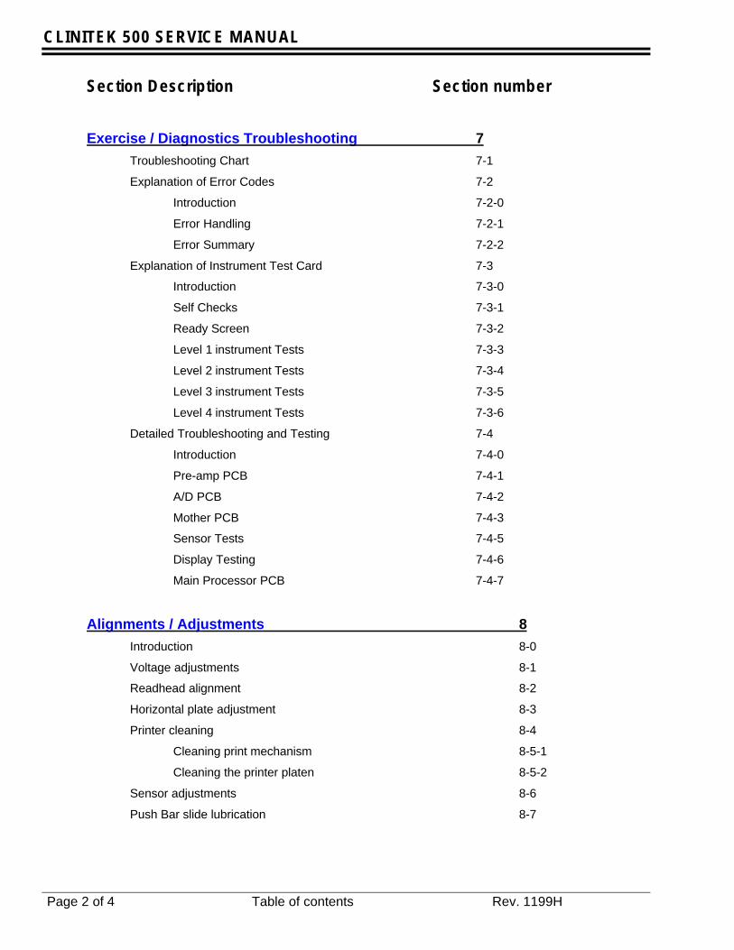
Exercise / Diagnostics Troubleshooting 7Troubleshooting Chart 7-1
Explanation of Error Codes 7-2
Introduction 7-2-0
Error Handling 7-2-1
Error Summary 7-2-2
Explanation of Instrument Test Card 7-3
Introduction 7-3-0
Self Checks 7-3-1
Ready Screen 7-3-2
Level 1 instrument Tests 7-3-3
Level 2 instrument Tests 7-3-4
Level 3 instrument Tests 7-3-5
Level 4 instrument Tests 7-3-6
Detailed Troubleshooting and Testing 7-4
Introduction 7-4-0
Pre-amp PCB 7-4-1
A/D PCB 7-4-2
Mother PCB 7-4-3
Sensor Tests 7-4-5
Display Testing 7-4-6
Main Processor PCB 7-4-7
Alignments / Adjustments 8Introduction 8-0
Voltage adjustments 8-1
Readhead alignment 8-2
Horizontal plate adjustment 8-3
Printer cleaning 8-4
Cleaning print mechanism 8-5-1
Cleaning the printer platen 8-5-2
Sensor adjustments 8-6
Push Bar slide lubrication 8-7

CLINITEK 500 SERVICE MANUAL
Section Description Section number
Rev.1199H Table of Contents Page 3 of 4
Repair / Replacement 9Introduction 9-0
Pusher Bar 9-1
PCMCIA 9-2
Printer Module 9-3
Bezel 9-4
Fixed Table 9-5
Moving Table 9-6
Upper Case 9-7
Fan 9-7-1
Table Guide Left 9-8
Table Guide Right 9-9
Power Supply 9-10
Processor PCB 9-11
SIMM PCB 9-11-1
Electronics Bracket 9-12
The Mother PCB 9-13
Strip Detector 9-14
Lamp 9-15
Preamp & A/D 9-16
A/D PCB 9-16-1
Preamp PCBs 9-16-2
Drive Housing 9-17
Crank Arm 9-18
Baseplate Mechanism 9-19
Lower Case Assembly 9-20
Lower Case 9-20-1
Touch Screen 9-21
Printer Interface PCB 9-22
Illustrated Parts Breakdown 10
Schematics 11
Release Testing 12
CLINITEK 500 SERVICE MANUAL
Section Description Section number
Page 4 of 4 Table of contents Rev. 1199H
Appendices CLINITEK 500 Instrument Release Test Data Collection Software A
Hard Standards Maintenance B
CLINITEK 200 Emulation Output Format Support C
CLINITEK 200+ Emulation Output Format Support D
Printer Report Formats E
Test Mode 2 and Altered Ranges F
CLINITEK Communications Standard CCS G
CLINITEK 500 Implementation of the CCS H
GENERAL DESCRIPTION
Rev. 1199H CLINITEK 500 Service Manual Page 1.1
1-0 IntroductionThe CLINITEK® 500 Urine Chemistry Analyzeris capable of processing in excess of 500-urine chemistry reagent test strips per hour. Itwas developed as the next generationreplacement system for Bayer’s CLINITEK®200+ Urine Chemistry Analyzer and differsprimarily from this system in its higherthroughput (over 500 tests per hour), non-pacing operation and enhanced touch-screenbased user interface. In addition to directsupport for a wide range of MULTISTIX®Reagent Strips, the Clinitek 500 instrumentcan make and report a qualitativedetermination of urine color.
1-1 FeaturesThe major improvement over previoussystems has been in workflow reduction.Customers can reduce their technician timespent on processing urine samples. Toachieve this overall benefit, the followingfeatures were implemented:
• Touch screen display for easier andfaster operation,
• Non-pacing operation mode toprocess samples at the users pace,
• Increased throughput for completingwork faster,
• Automatic urine color determination tospeed up data entry,
• Confirmatory Sieve with Batch ResultsEditing to eliminate time consumingmainframe editing,
• Memory Recall which allowscustomers to display the test resultsfrom specific samples,
• Interactive Bar Code Reader Support(optional) to enter patient ID and colorand clarity more efficiently,
• Internal Automatic Calibration toimprove reliability of results.
• No warm-up time for starting a batch.
• User Interface available in English, German,French , Italian, Spanish and Kanji withapplicable help screens The generaldescription of the CLINITEK® 500 UrineChemistry Analyzer can be found on pages 1.0to 1.5 in the Operating Manual.
1-2 General Specifications
Size:Depth-32.4 cm (12.8 in.)Width-37.7 cm (14.8 in.)Height-28.2 cm (11.1 in.)
Weight:7.4 Kg (16.3 lb)
Input voltage:Auto Ranging 90 VAC to 264 VAC50 – 60 Hz
Maximum Power Input-72VA
Thermal output:246 BTU/hr
Line Leakage Current:< 0.5 milliamperes in normal condition< 3.5 milliamperes in single fault condition
(Testing protocol and allowable limits as specified bythe safety standards for laboratory equipmentoutlined in UL 3101-1, CSA 22.2 No. 1010.1 and IEC1010-1)
Ambient Operating Temperature Range:18°C to 30°C (64°F to 86°F
Ambient Operating Humidity Range:20% to 85% relative humidity
Optimum Operating Conditions:22°C to 26°C (72°F to 86°F)
35% to 55% relative humidity
CHAPTER ONE - GENERAL DESCRIPTION Return
GENERAL DESCRIPTION
Page 1.2 CLINITEK 500 Service Manual Rev. 1199H
METHODS OVERVIEW
Rev. 1199H CLINITEK 500 Service Manual Page 2.1
Chapter Two - Methods Overview Return
2-0 IntroductionThe CLINITEK 55 00 Urine Chemistry Analyeris a scanning reflectance photometer, whichreads the change in color on Bayer Multistix®Reagent Strips. Please refer to the productinsert that comes with the specific Multistx®Reagent Strips being used for a descriptionof the its methods.
METHODS OVERVIEW
Page 2.2 CLINITEK 500 Service Manual Rev. 1199H

INSTALLATION
Rev. 1199H CLINITEK 500 Service Manual Page 3.1
3-0 IntroductionRefer to the installation section of theOperating Manual.
CHAPTER THREE – INSTALLATION Return
INSTALLATION
Page 3.2 CLINITEK 500 Service Manual Rev. 1199H
OPERATIONS / PROCEDURES
Rev.1199H CLINITEK 500 Service Manual Page 4.1
4-0 IntroductionRefer to sections 3 and 4 of the OperatingManual for instructions on the operation ofthe CLINITEK500 Urine ChemistryAnalyzer.
CHAPTER FOUR – OPERATIONS / PROCEDURES Return
OPERATIONS / PROCEDURES
Page 4.2 CLINITEK 500 Service Manual Rev.1199H

PREVENTIVE MAINTENANCE
Rev. 1199H CLINITEK 500 Service Manual Page 5.1
5-0 IntroductionThis section describes cleaning and preventativemaintenance test procedures that should beperformed as a matter of routine anytime that aCLINITEK 500 instrument is in Bayer Diagnosticspossession. Following these procedures will helpidentify possible system weaknesses prior tothem manifesting themselves as field failures.
5-1 Cleaning
Reference
CLINITEK 500 Operating Manual, Section 5“CARE OF THE INSTRUMENT” for cleaninginstructions.
5-2 Lubrication
Push Bar Slide Arm Shaft
1. Clean the Push Bar Slide Arm Shaft withalcohol.
2. Apply a thin coat of Lubriplate 630-AA Multi-purpose Grease, part number 50336008.
Introduction ------------------------------------------------------------------------------------------------------5-0Cleaning ----------------------------------------------------------------------------------------------------------5-1Lubrication -------------------------------------------------------------------------------------------------------5-2
CHAPTER FIVE - PREVENTIVE MAINTENANCE Return
PREVENTIVE MAINTENANCE
Page 5.2 CLINITEK 500 Service Manual Rev. 1199H
FUNCTIONAL DIAGRAMS / THEORY
Rev.1199H CLINITEK 500 Service Manual Page 6.1
6-0 IntroductionThe CLINITEK 500 Instrument is a stand-alone,semi-automatic urine chemistry analyzer. Theinstrument is a scanning reflectance photometercapable of outputting clinically significantdiagnostic results when used with a variety ofBayer reagent strips.
Primary features of the system include the abilityto automatically detect the presence of a Bayerreagent test strip which has been presented forprocessing, a throughput in excess of 500reagent tests per hour and an advanced touch-screen based user interface which gives thecustomer considerable control over the operationof the system.
The instrument has several functional sub-systems: Reagent Transport, Readhead system,Data processing and User interface. Within eachof these sub-systems there are specific electrical,mechanical and software components. Theoverall operation of the instrument is controlled bytwo independent processors, the first managingdata I/O and the user interface. The secondcontrolling basic instrument hardware functions.
6-1 General OperationThe general operation of the instrument is asfollows:1. (Refer to figure 6-1)
2. The user dips a Bayer urine test strip into aurine sample and places it onto the load zoneof the CLINITEK 500 instrument’s Fixed Table.
3. A strip detector senses the presence of areagent strip on the Fixed Table.
4. Detection of a reagent strip activates the Pushbar that pushes the reagent strip to the rightside of the load zone on the Fixed Table.
5. When the Push bar reaches the far right endof its travel, the strip detector verifies thepresence of a reagent strip. If a strip ispresent, the test sequence number isincremented and the Moving Table isactivated to move the reagent strip into theReadhead area in preparation for analysis.(This area is encased under a permanenthood to prevent ambient light from interferingwith the system's reflectance measurements.)
6. The Moving Table continues to be activatedevery 7 seconds and advances the strip tothe right each time by approximately.45 inches (1.143 cm). top of chapter
Section
Introduction-------------------------------------------------------------------------------------------------------6-0General Operation----------------------------------------------------------------------------------------------6-1User Interface----------------------------------------------------------------------------------------------------6-2Power Distribution ----------------------------------------------------------------------------------------------6-3Mother PCB ------------------------------------------------------------------------------------------------------6-4Motor Drive Circuits --------------------------------------------------------------------------------------------6-4-1
Optical Sensors -----------------------------------------------------------------------------------------6-4-2Printer Interface -----------------------------------------------------------------------------------------6-4-3Serial Ports -----------------------------------------------------------------------------------------------6-4-4
Moving table -----------------------------------------------------------------------------------------------------6-5Main PCB---------------------------------------------------------------------------------------------------------6-6Touch Screen Display -----------------------------------------------------------------------------------------6-7Readhead System Overview---------------------------------------------------------------------------------6-8
Readhead Movement ----------------------------------------------------------------------------------6-8-1Pre-amp PCB----------------------------------------------------------------------------------------------------6-9Pre-amp A/D PCB ----------------------------------------------------------------------------------------------6-10Strip Detector ----------------------------------------------------------------------------------------------------6-11
CHAPTER SIX – FUNCTIONAL DIAGRAMS / THEORY Return

FUNCTIONAL DIAGRAMS / THEORY
Page 6.2 CLINITEK 500 Service Manual Rev. 1199H
7. The Moving Table advancement places a stripunder either Readhead (at approximately 25or 67 seconds after dipping),if a strip is undereither readhead then the Readhead will scanthe strip taking measurements in the Red,Blue, Green and IR wavelengths.
8. After a Strip has been read under bothreadheads the data will be analyzed and theresults passed to processor “1“ for output todevices based upon system configurationoptions selected by the user. top of chapter

FUNCTIONAL DIAGRAMS / THEORY
Rev.1199H CLINITEK 500 Service Manual Page 6.3
Instrument Operation Overview Block Diagram
Figure 6-1
Strip placed on load zone
Push Bar moves strip to verificationposition
Strip present at right side detector
Pusher moves strip to Moving tablepick-up and stays at far rightposition
Moving table advances 3 positions(3 instrument cycles, 21 seconds)
Push Bar returns to left position
NO
Readhead 1 detects strip present
Strip at either readhead
Initialize readhead position
Calibrate
Read strip(s)
Select readings
Calculate reflectances
NO
Push Bar returns toleft position
Ready
YES
NO
YES
NO
Have12 moving table cyclesoccurred without detecting a stripunder readhead 1
NO
YES
yes
Push Bar moves strip to themoving table pick up
Push Bar returns to the far leftand waits for next strip
Moving table advances stripevery 7 seconds
yes

FUNCTIONAL DIAGRAMS / THEORY
Page 6.4 CLINITEK 500 Service Manual Rev. 1199H
6-2 User InterfaceThe user interface consists of: a touch screendisplay, audible and visual alarms, internal andexternal printer options, a serial RS232 input forbar-coded sample ID, a second RS232, data portfor interface with an external customersinformation system (computer) and a third RS232serial port for future customer options. All userinterface functions are controlled by processor#1. top of chapter
6-3 Power DistributionThe AC line input for the instrument first passesthrough the power entry module. This module is acombination of an on/off switch and line cordreceptacle. Note that the AC line fusing for thisproduct is located inside of the power supplymodule and is not considered a serviceable item.
The power supply is a switching power supply.The AC input voltage is automaticallycompensated for and has a range of 90-264 VAC,50-60 Hz. The outputs of this supply are +5 VDCand +12 VDC, -12 VDC and -5 VDC. The exactvoltage level of the +5 VDC output can beadjustable by use of potentiometer V1 adjacent toterminal block TB2 (refer to figure 8-1). Thepower supply is protected from overload by useof fold-back current protection and an internalfuse. An internal over-temperature protectioncircuit with automatic reset provides additionalprotection. Output noise and ripple will be less
than .3% RMS (noise) and 1% peak-to-peak(ripple) for the main +5 VDC output.
Power is distributed throughout the instrument viathe MOTHER PCB. A cable connects the powersupply to connector P12 of the MOTHER PCB.Connector P12 is a six pin connector and has thefollowing pin out: Pins 2 and 3 of this connectorare the DC ground, pin 1 is -12 VDC, pins 4 and 5+5 VDC and pin 6 +12 VDC.
There are two auto reset fuses F1 and F2 whichare soldered into the MOTHER PCB and providecurrent protection for the external Bar codereader. Fuse F1 is for the +5 VDC and fuse F2 isfor +12 VDC
Power to the internal printer is supplied viaconnector P7 on the MOTHER PCB, Pins 1 and 2are +5 VDC, Pin 3 is DC Ground.
The strip detector circuit operates off both+12 VDC and –12 VDC. This power is suppliedthrough connector P8 of the MOTHER PCB. Pins1,4 and 5 are GND while pin 3 is +12 VDC andpin 2 is –12 VDC. top of chapter
6-4 Mother PCBThe MOTHER PCB serves primarily as aninterconnection board for many of the system’sI/O functions and contains a portion of theinstrument’s control circuitry. Each of thefunctions performed by the MOTHER PCB isdescribed below.
Main PCB
Processor #1
Mother PCBPrinter Bar-code reader RS232
RS232 Ports
InternalPrinter
ExternalPrinter
Bar-CodeReader
RS232RJ45
RS232DB25
TouchScreenDisplay
Figure 6-2
FUNCTIONAL DIAGRAMS / THEORY
Rev.1199H CLINITEK 500 Service Manual Page 6.5
6-4-1 Motor Drive Circuits
The drive circuits for the moving table, Push barand readhead all utilize the same circuit design.U5, U6 and U7 are motor controller IC’s whichconvert the instructions from Processor #2(connector J2) to drive signals for the steppermotors. The input signals are Step (pin 11), OE(pin 15), and Direction (pin 14). The half stepcontrol line is tied high to the +5 VDC thusdisabling this function on all IC’s. U6 also has pin11 tied to the +5 VDC which fixes the motordirection to clockwise rotation.
The output of the motor controller IC drives a fourphase stepper motor. The outputs are: pin 8 (Aoutput), pin 1 (B output), pin 6 (C output) and pin3 (D output). Each of the outputs is clamped toground through a reversed bias schottky diodes(D1-D12).
The stepper motors are four phase and havetypical coil resistances as follow:
Readhead motor 24 ohmsPush Bar motor 53 ohmsMoving Table motor 32 ohms
6-4-2 Optical Sensors
There are three optical sensors that are used toconfirm the following:
1. Fixed Table is in place (PN 40453222)
2. Push Bar interrupt sensor (PN 40453233)
3. Moving Table interrupt sensor (PN 40453221)
All of the sensor outputs are routed to the MainPCB through connector J1
The Fixed Table in place optical sensor is locatedon the left support of the fixed table guide and isused to determine if the fixed table is fully seated.The sensor plugs into connector P10 on theMother PCB. If the signal is not present it willresult in a general system error “26” and will haltoperation.
The Push bar interrupter is used to determine ifthe push bar has cycled completely. The sensorplugs into connector P9 on the MOTHER PCB. Ifthe signal is not present it will result in a generalsystem error “24” and will halt operation.
The Moving Table interrupter is used to determineif the strip transport is working properly. Oncethe system initiates a test cycle and activatesthose mechanisms used to advance a regent teststrip, it expects to see a signal change from thissensor within a certain time window. This sensorplugs into connector P1 on the MOTHER PCB. Ifa signal is not seen, the system interprets this asa problem with the moving table and reports ageneral error “23” which will halt operation.
6-4-3 Printer interface
The external printer port J3 is located on theMother PCB. In addition to providing the routingfrom Main PCB connector J1, to connector J3mounted to the rear of the instrument, the datalines are clamped for noise suppression withdiodes D14 through D24.
6-4-4 Serial Ports
The Mother PCB also provides interconnectionfrom the Main PCB (connector J2) to the threeRS232 serial ports J5, J6 and P4. Connector J6 isa RJ45 8 pin modular jack and connector P4 is a25 pin female D-Connector. These are for serialcommunication with external equipment.
The remaining port J5 is an 8 pin RJ45 connectorthat is dedicated for use with a bar code reader.On this jack, pins 1 & 3 are tied to ground, pin 4is serial output from the Main PCB, pin 5 is serialinput. Pin 6 provides +5 VDC output and pin 7provides a +12 VDC output for the reader.
6-4-5 Moving table
Following confirmation of reagent strip presenceby the strip detector, movement of the reagenttest strip is then performed by the moving tableassembly. This assembly is driven by a steppermotor which is under the direct control ofProcessor 2 (Refer to figure 6-3).

FUNCTIONAL DIAGRAMS / THEORY
Page 6.6 CLINITEK 500 Service Manual Rev. 1199H
Processor #2 sends control signals for directionand a pulse train to the stepper motor controllerchip on the mother PCB. The controller convertsthe pulse train into four outputs; phase A, phaseB, phase C, phase D, for the windings of thestepper motor. An optical interrupter detector isused to establish a home location for the movingtable and provides a means of timing its operationto detect errors in its motion. (Refer to section 6-4-1 for more details on the motor drive circuits)
6-5 Main PCBThe Main PCB contains the instrument’s twoProcessors and all of their associated supportcircuitry. Processor #1 (U21) is an 80C517A(8051 family) which is a surface mount IC.Processor #2 (U1) is a Dallas DS2253T and ismounted as a SIMM in a socket. The systemutilizes the Processors as follows:
Processor #1 is used for serial communications,bar code communications, internal and externalprinter functions, converting decode values toclinical levels, and provides all user interfacefunctions. It communicates with Processor #2and includes the ability to program Processor #2.
Processor #2 is used to control strip movement(strip detector, push bar motor, moving tablemotor), readhead movement, perform errorchecking, read the strip, perform calculations onstrip data, store one set of results (reflectance,decodes and color) and maintain real time anddate.
The PCMCIA card is used to store the CT 500software and to retain the user configurationsettings.
IC U24 is the system RAM (128K) that is used tostore patient results.
IC’s U13 &U14 are quad comparators used inconjunction with DAC U29 and processor 2 forthe strip detector control.
Data for the internal printer is sent to latch U17where it is output through an octal ferrite to theprinter on connector J3.
Data for the external printer is sent to U19, abuffer, where in conjunction with a response to astrobe signal it is sent out connector P1.
The Touch Screen Display is connected to theMain PCB at connector J5. Data from Processor#1 is sent to a latch U15 where it is then clockedto the display. Information is entered from thetouch screen keyboard and is passed throughconnector J5 to Processor #1. Power is suppliedto the display via connector J5 pins 16 & 17 forthe +5 VDC and pins 18 & 19 for the +12 VDC.Pins 4,5,20,21,24,29 and 30 are grounded. top of chapter
6-6 Touch Screen DisplayThe touch screen display assembly consists offour main components: The bezel assembly,touch screen, display and the interface PCB.
The Display is a 320 by 240 dot matrix (15 linesby 40 characters) and is controlled by the displaycontroller U1 (SED133SF) on the interface PCB.The information is presented to the controller inan eight bit parallel format from the Main PCB viaprocessor #1. It is then converted to a videoformat and sent to the display as pixels.
The touch screen is an Analog Resistive TouchScreen (ARTS). It consists of two layers (oneorientated along the X-axis and one layerorientated along the Y-axis) of a transparentresistive film separated by a spacer. The activeaxis of the screen is selected via two controlsignals which switch one of two pair of MOSFETS(U4) on to apply a fixed voltage across the axis ofthe resistive element. The inactive elementbecomes the input for the A/D convert. R1 is apull down resistor for the vertical axis and R2 is apull down resistor for the horizontal axis. Whenthe screen is pressed a unique voltage isgenerated for both the X layer and the Y layer.These two voltages are converted to a digital
Processor #2
Mother PCBStepper motordrive circuits
Optical sensor(PN 40453221)
Moving tableAssembly
Stepper motor
Figure 6-3

FUNCTIONAL DIAGRAMS / THEORY
Rev.1199H CLINITEK 500 Service Manual Page 6.7
representation of the location on the screen bythe A/D converter in Processor #1. top of chpater
6-7 Readhead System OverviewThe Readhead system consists of the followingcomponents: Two Pre-amps, an A/D convertersubsystem, two independent illumination sources,a drive subsystem and a system controller. Theinstrument uses two readheads that are spacedto allow for two readings of a strip. The firstreading occurs approximately 25 seconds afterthe strip has been dipped and the secondreading at about 67 seconds. Each of thereadheads consists of a light source and fourdetectors. The detectors each have an opticalfilter that passes a broad bandwidth of energy tothe detector. The four bands passed to thedetectors are Infrared, Red, Green and Blue. Theoutput of each detector is passed to a two-stageamplifier. (See section 6-9 Pre-amp theory)
The four outputs (IR, Red, Green and Blue) fromeach of the two pre-amps PCB’s are routed to acommon A/D PCB. The A/D PCB contains aneight-channel A/D converter that is multiplexed toselect which of the eight channels will beconverted. Its output is sent in a serial format toProcessor #2 (Refer tosection 6-10 A/D theory).Processor #2 controls the operations of readingthe strips and calculating the results. Once theresults are calculated, they are sent to Processor#1 which controls the User Interface. top of chapter
6-8 Readhead Movement
The two readheads of the CLINITEK® 500 aremounted to a Readhead carrier that rides on aprecision ball slide and is driven by means of astepper motor. The process of taking a readinginvolves moving this assembly over the reagentstrip(s) and scanning each reagent strip takingone or more readings at every pad location.Processor #2 controls the position of theReadhead carrier (See section 6-4-1 motorcontrol theory).
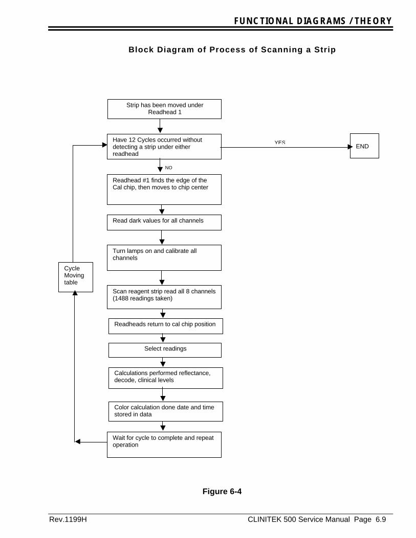
The actual process of reading a strip issummarized below:
The scan cycle is 7 seconds.
1. Strip presence is verified by the stripdetector.
2. Processor #2 activates the moving table toadvance the reagent strip into the Readheadarea. It takes three cycles for a reagent stripplaced on the load area to be brought underReadhead #1.
3. If a strip was under Readhead #1 during theprevious scan cycle, a control code is sent toprocessor #2. (A strip is verified as beingpresent at Readhead #1 if the IR channelreflectance between pads 9 and 10, and pads2 and 3 is above 65% is present in the lastdata set)
4. If a strip was present at Readhead #2 duringthe last cycle, the data set, which includeserror code, is sent to processor #1. The errorflags are reset after the error code is sent. (Ifboth events 3 and 4 occur a code will be sentfirst)
5. At 3.0 seconds into the 7 second scan cycle,the actual read operation begins:
A. Move the Readheads to find the edge ofthe cal-chip under readhead #1 andmove to the center of the cal chip. Thisis arbitrarily set as location 0.
B. Perform a dark value reading on allchannels.
C. Turn the lamps on and perform acalibration of all channels on the whitecal chip.
D. Move the Readheads out 0.017” andread each of the eight channels after theReadheads have moved. Thesereadings consist of the A/D convertervalues associated with each channel. Allof the readings are stored in the ordertaken in temporary memory.
E. Repeat this until 1488 readings of 2 byteseach are read, dark values subtractedfrom this and the resultant values storedfor each Readhead during the scancycle.
F. The Readheads are returned to the calchip location.
FUNCTIONAL DIAGRAMS / THEORY
Page 6.8 CLINITEK 500 Service Manual Rev. 1199H
6. Calculations are performed based on thespecifics of the reagent strip being tested.Not all data is used in these calculations (forexample, for most MULTISTIX reagents, onlythe reading closest to the center of thereagent pad is used in the determination ofresults for that analyte).
Calculations are done to obtain reflectances,which, after processing in the specificalgorithm for a reagent, is compared to adecode point, and converted into a reportableclinical level. Each of the interim and finalresults is stored in the appropriate data set.
After all individual pad calculations arecompleted the color calculations are doneand stored. The date, time and sequencenumber, are sent in the data set. Thesequence number is then incremented.
7. The system then waits until the 7-second scancycle is completed. The process thenrepeats until there are no more reagent stripsunder the hood area. top of chapter
FUNCTIONAL DIAGRAMS / THEORY
Rev.1199H CLINITEK 500 Service Manual Page 6.9
Figure 6-4
Block Diagram of Process of Scanning a Strip
Strip has been moved underReadhead 1
Have 12 Cycles occurred withoutdetecting a strip under eitherreadhead
Readhead #1 finds the edge of theCal chip, then moves to chip center
Read dark values for all channels
Turn lamps on and calibrate allchannels
Scan reagent strip read all 8 channels(1488 readings taken)
Readheads return to cal chip position
Calculations performed reflectance,decode, clinical levels
Color calculation done date and timestored in data
Wait for cycle to complete and repeatoperation
NO
ENDYES
Select readings
CycleMovingtable

FUNCTIONAL DIAGRAMS / THEORY
Page 6.10 CLINITEK 500 Service Manual Rev. 1199H
6-9 Pre-amp PCBThe CT500 has two functionally identicalReadheads. The heart of each Readhead is thesurface mounted detector package. This devicehas four separate channels each with its ownoptical filter: one green, one infrared, one blueand one red. Each of the channels has it’s ownphoto detector output. The output of the detectoris passed through a two-stage Pre-amp and itsoutput through connector P1.The op-amps used on the Pre-amp operate from a+5VDC and -5VDC power supply located on theA/D PCB. When the lamp in the readhead is onand it is over the calibration chip the output ofeach of the Pre-amp channels should beapproximately +4VDC. With the Readhead lampoff, the outputs of the pre-amp channels shouldbe approximately 0VDC (because the op-ampsoperate from the both a positive and negativesupply up to a.4 positive or .4 negative voltagemay be observed). top of chapter
CAUTION
Cotton gloves must be worn whenhandling the Preamp PCBs.
ESD percautions must be taken wheneverthe upper case of the instrument isremoved.
A dirty Preamp PCB can cause errors 02-1 and 02-2.
6-10 Pre-amp A/D PCBThe Pre-amp A/D PCB receives the analogsignals from both Pre-amp PCBs and convertsthese voltages to digital values. This count is theraw value that is used in the algorithms tocalculate reflectance.
The Analog to Digital conversion is performed byIC U1 an eight channel analog multiplexing A/Dconverter with serial output. There are also fourvoltage regulators on the PCB. Voltage regulatorVR1 provides a +4 VDC reference for the A/Dconverter. Voltage regulator VR2 provides the +5VDC used by both readheads pre-amp PCB andthe A/D board. Voltage regulator VR3 providesthe –5 VDC used by both readhead pre-ampPCB’s and the A/D board. Voltage regulator VR4provides the + 6 VDC for the lamps in bothreadheads. Power is supplied to the A/D PCB
from the processor PCB via connector P3; pins 9&10 provide +12 VDC and pin 6 provides -12VDC. top of chapter
6-11 Strip DetectorThe strip detector contains 5 high output redLED's and 4 detectors spaced between theLED's. (Presently, the LED at the left of thedetector is not used.) Every 100 milliseconds,when the Push Bar is at the left most position, oneof the LED’s is pulsed ON for about 16microseconds. The five strip detectors LED’s areturned ON one at a time, sequentially from thetimer interrupt routine. The LED's are disabledduring the time the “Push Bar” is moving orlocated at the right side.
Light reflected back by the presence of a strip ispicked up by an associated detector and triggersa level sensitive circuit connected to an input porton the processor. Each detector has two"detection level-setting" circuits associated with it,one for each of the two LED's with which itoperates. The detection levels are calibrated onlywhen the instrument power is turned on, when nostrip is on the table (The fixed table needs to bein place when the instrument is powered on forproper detector calibration). For each of the 8detector-LED pairs, the detection level count isfound where light from the table just causesdetection. Then the setting is increased by apercentage of the count for low level signals andfor high level signal it adds a constant, so that astrip is necessary to cause detection. When thestrip detector setup is printed out using theInstrument test card (Refer to section 7-3-4-4) theprintout will show the detector calibration valuesfor both of its LEDs
Notice that L5D5 is printed twice. The secondcalibration level is used for the “Strip Verification”position and has a lower detector gain setting toprevent false verification.
Example of Strip Detector Set-up print-out
L1D1 L2D1 L2D2 L3D2
L3D3 L4D3 L4D4 L5D5 L5D5

FUNCTIONAL DIAGRAMS / THEORY
Rev.1199H CLINITEK 500 Service Manual Page 6.11
Note
On early units, a 5th LED on the far left may bepresent but disabled. The Set-Up value L1D1 iscalculated but is not used by the software.
The calibration compensates for variations in LEDoutput, detector sensitivity, and table reflectancechanges. The strip detector is AC coupled, toreduce the effect of ambient light.
The detector circuits require both +12 volts and –12 volts for operation which is supplied viaconnector P1: pin 3 (+12 VDC), pin 2 (-12 VDC)and pins 1, 4 and 5 are ground.
The instrument only calibrates the strip detectorduring the power on cycle. top of chapter

FUNCTIONAL DIAGRAMS / THEORY
Page 6.12 CLINITEK 500 Service Manual Rev. 1199H
EXERCISE / DIAGNOSTICS TROUBLESHOOTING
Page 7.1 CLINITEK 500 Service Manual Rev. 1199H
7-0 IntroductionThis chapter is divided into four distinct sections.Each of the sections has its own table of contentsat its beginning.
CHAPTER SEVEN – EXERCISE / DIAGNOSTICS ReturnTROUBLESHOOTING
Section
Troubleshooting Table-----------------------------------------------------------------------------------------7-1Explanation of Error Codes ----------------------------------------------------------------------------------7-2Explanation of Instrument Test Card-----------------------------------------------------------------------7-3Detailed Troubleshooting and Testing---------------------------------------------------------------------7-4
EXERCISE / DIAGNOSTICS TROUBLESHOOTING
Page 7.2 CLINITEK 500 Service Manual Rev. 1199H
EXERCISE / DIAGNOSTICS TROUBLESHOOTING
Rev.1199H CLINITEK 500 Service Manual Page 7.3
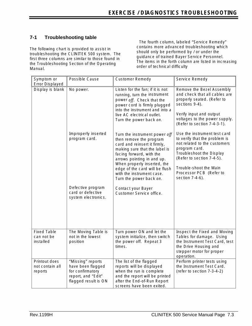
7-1 Troubleshooting table
The following chart is provided to assist introubleshooting the CLINITEK 500 system. Thefirst three columns are similar to those found inthe Troubleshooting Section of the OperatingManual.
The fourth column, labeled “Service Remedy”contains more advanced troubleshooting whichshould only be performed by / or under theguidance of trained Bayer Service Personnel.The items in the forth column are listed in increasingorder of technical difficulty
Symptom orError Displayed
Possible Cause Customer Remedy Service Remedy
Display is blank No power.
Improperly insertedprogram card.
Defective programcard or defectivesystem electronics.
Listen for the fan; if it is notrunning, turn the instrumentpower off. Check that thepower cord is firmly pluggedinto the instrument and into alive AC electrical outlet.Turn the power back on.
Turn the instrument power offthen remove the programcard and reinsert it firmly,making sure that the label isfacing forward, with thearrows pointing in and up.When properly inserted, theedge of the card will be flushwith the instrument case.Turn the power back on.
Contact your BayerCustomer Service office.
Remove the Bezel Assemblyand check that all cables areproperly seated. (Refer tosections 9-4).
Verify input and outputvoltages to the power supply.(Refer to section 7-4-3-1).
Use the instrument test cardto verify that the problem isnot related to the customersprogram card.Troubleshoot the Display(Refer to section 7-4-5).
Trouble-shoot the MainProcessor PCB (Refer tosection 7-4-6).
Fixed Tablecan not beinstalled
The Moving Table isnot in the lowestposition
Turn power ON and let thesystem initialize, then switchthe power off. Repeat 3times.
Inspect the Fixed and MovingTables for damage. Usingthe Instrument Test Card, testthe Drive Housing andstepper motor for properoperation.
Printout doesnot contain allreports
“Missing” reportshave been flaggedfor confirmatoryreport, and “Edit”flagged result is ON
The list of the flaggedreports will be displayedwhen the run is completeand the report will be printedafter the End-of-Run Reportscreens have been exited.
Perform printer tests usingthe Instrument Test Card.(refer to section 7-3-4-2)

EXERCISE / DIAGNOSTICS TROUBLESHOOTING
Page 7.4 CLINITEK 500 Service manual Rev.1199H
Symptom orError Displayed
Possible Cause Customer Remedy Service Remedy
Push bar doesnot move to theright after astrip is placedonto theplatform.
Other strips arebeing moved alongthe platform.
Strip Detectorproblem.
Allow up to 7 seconds toelapse before movement ofthe push bar. The time lapsedepends upon the timingcycle for movement of thestrips across the platform.
From the Ready/Run screen(and with the run complete),turn the instrument power off,wait several seconds, thenturn it back on. If theproblem continues, contactyour Bayer Customer Serviceoffice.
Verify that the Strip DetectorLEDs are turning on.
Verify that the customer’ssystem is in the Ready/Runstate.
Check that the cable from thepush arm motor is seatedinto connector P14 on themother PCB.
Use the instrument test cardto check operation.(Refer to section 7-3-6-3).
Verify strip detector operation(Refer to section7-3-4-4).
Verify that the strip detectorhas correct voltages (Refer tosection 7-4-3-2).
Replace the strip detector(Refer to section 9-14).
Trouble shoot the MAIN PCBfor a broken trace andreplace if necessary (Refer tosection 7-4-6).
EXERCISE / DIAGNOSTICS TROUBLESHOOTING
Rev.1199H CLINITEK 500 Service Manual Page 7.5
Symptom orError Displayed
Possible Cause Customer Remedy Service Remedy
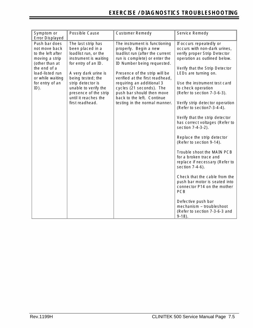
Push bar doesnot move backto the left aftermoving a strip(other than atthe end of aload-listed runor while waitingfor entry of anID).
The last strip hasbeen placed in aloadlist run, or theinstrument is waitingfor entry of an ID.
A very dark urine isbeing tested; thestrip detector isunable to verify thepresence of the stripuntil it reaches thefirst readhead.
The instrument is functioningproperly. Begin a newloadlist run (after the currentrun is complete) or enter theID Number being requested.
Presence of the strip will beverified at the first readhead,requiring an additional 3cycles (21 seconds). Thepush bar should then moveback to the left. Continuetesting in the normal manner.
If occurs repeatedly oroccurs with non-dark urines,verify proper Strip Detectoroperation as outlined below.
Verify that the Strip DetectorLEDs are turning on.
Use the instrument test cardto check operation(Refer to section 7-3-6-3).
Verify strip detector operation(Refer to section7-3-4-4).
Verify that the strip detectorhas correct voltages (Refer tosection 7-4-3-2).
Replace the strip detector(Refer to section 9-14).
Trouble shoot the MAIN PCBfor a broken trace andreplace if necessary (Refer tosection 7-4-6).
Check that the cable from thepush bar motor is seated intoconnector P14 on the motherPCB
Defective push barmechanism – troubleshoot(Refer to section 7-3-6-3 and9-18).
EXERCISE / DIAGNOSTICS TROUBLESHOOTING
Page 7.6 CLINITEK 500 Service manual Rev.1199H
Symptom orError Displayed
Possible Cause Customer Remedy Service Remedy
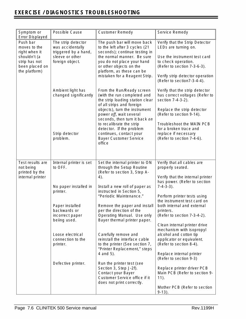
Push barmoves to theright when itshouldn’t (astrip has notbeen placed onthe platform)
The strip detectorwas accidentallytriggered by a hand,sleeve or otherforeign object.
Ambient light haschanged significantly
Strip detectorproblem.
The push bar will move backto the left after 3 cycles (21seconds); continue testing inthe normal manner. Be sureyou do not place your handor other objects on theplatform, as these can bemistaken for a Reagent Strip.
From the Run/Ready screen(with the run completed andthe strip loading station clearof all strips and foreignobjects), turn the instrumentpower off, wait severalseconds, then turn it back onto recalibrate the stripdetector. If the problemcontinues, contact yourBayer Customer Serviceoffice
Verify that the Strip DetectorLEDs are turning on.
Use the instrument test cardto check operation.(Refer to section 7-3-6-3).
Verify strip detector operation(Refer to section7-3-4-4).
Verify that the strip detectorhas correct voltages (Refer tosection 7-4-3-2).
Replace the strip detector(Refer to section 9-14).
Troubleshoot the MAIN PCBfor a broken trace andreplace if necessary(Refer to section 7-4-6).
Test results arenot beingprinted by theinternal printer
Internal printer is setto OFF.
No paper installed inprinter.
Paper installedbackwards orincorrect paperbeiing used.
Loose electricalconnection to theprinter.
Defective printer.
Set the internal printer to ONthrough the Setup Routine(Refer to section 3, Step A-4).
Install a new roll of paper asinstructed in Section 5,“Periodic Maintenance.”
Remove the paper and installper the direction of theOperating Manual. Use onlyBayer thermal printer paper.
Carefully remove andreinstall the interface cableto the printer (See section 7,“Printer Replacement,” steps4 and 5).
Run the printer test (seeSection 3, Step J-2f).Contact your BayerCustomer Service office if itdoes not print correctly.
Verify that all cables areproperly seated.
Verify that the internal printerhas power. (Refer to section7-4-3-3).
Perform printer tests usingthe instrument test card onboth internal and externalprinters.(Refer to section 7-3-4-2).
Clean internal printer drivemechanism with isopropylalcohol and cotton tipapplicator or equivalent.(Refer to section 8-4).
Replace internal printer(Refer to section 9-3)
Replace printer driver PCBMain PCB (Refer to section 9-11).
Mother PCB (Refer to section9-13).
EXERCISE / DIAGNOSTICS TROUBLESHOOTING
Rev.1199H CLINITEK 500 Service Manual Page 7.7
Symptom orError Displayed
Possible Cause Customer Remedy Service Remedy
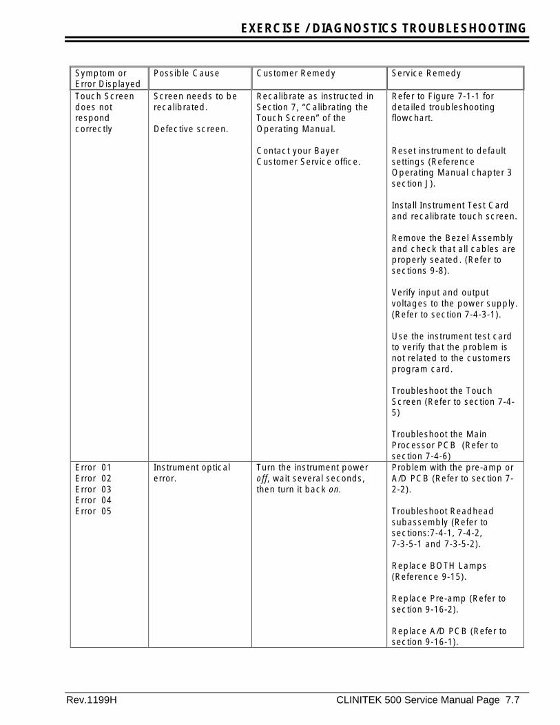
Touch Screendoes notrespondcorrectly
Screen needs to berecalibrated.
Defective screen.
Recalibrate as instructed inSection 7, “Calibrating theTouch Screen” of theOperating Manual.
Contact your BayerCustomer Service office.
Refer to Figure 7-1-1 fordetailed troubleshootingflowchart.
Reset instrument to defaultsettings (ReferenceOperating Manual chapter 3section J).
Install Instrument Test Cardand recalibrate touch screen.
Remove the Bezel Assemblyand check that all cables areproperly seated. (Refer tosections 9-8).
Verify input and outputvoltages to the power supply.(Refer to section 7-4-3-1).
Use the instrument test cardto verify that the problem isnot related to the customersprogram card.
Troubleshoot the TouchScreen (Refer to section 7-4-5)
Troubleshoot the MainProcessor PCB (Refer tosection 7-4-6)
Error 01Error 02Error 03Error 04Error 05
Instrument opticalerror.
Turn the instrument poweroff, wait several seconds,then turn it back on.
Problem with the pre-amp orA/D PCB (Refer to section 7-2-2).
Troubleshoot Readheadsubassembly (Refer tosections:7-4-1, 7-4-2,7-3-5-1 and 7-3-5-2).
Replace BOTH Lamps(Reference 9-15).
Replace Pre-amp (Refer tosection 9-16-2).
Replace A/D PCB (Refer tosection 9-16-1).

EXERCISE / DIAGNOSTICS TROUBLESHOOTING
Page 7.8 CLINITEK 500 Service manual Rev.1199H
Symptom orError Displayed
Possible Cause Customer Remedy Service Remedy
Error 06-2 A reagent strip thathad been detected atthe first readheadwas not detected atthe secondreadhead.
Touch the Return toReady/Run button to cancelthe run and return to theReady/Run screen, then turnoff the instrument power.Remove Push Bar and theFixed Table to locate thestrip (Refer to section 5,“Daily Cleaning”). Check thepins on the Moving Table toensure that none are bent orbroken. Perform the “DailyCleaning” and “WeeklyCleaning” procedures insection 5. Check yourprintout of results, or theResults Error Reportdisplayed at the end of therun, to determine thespecimen(s) for which thereare no results; retest thosespecimens.
Verify that Fixed Table seatscorrectly (Refer to section 9-5).
Verify that Moving Tableseats correctly (Refer tosection 9-6).
Perform Strip Walk Test(Refer to section 7-3-3-6).
Replace Drive housing(Refer to section 9-17).
Replace Fixed Table andMoving Table (Refer tosection 9-5, 9-6).
Replace Table Guides (Referto sections 9-8, 9-9).
Error 07-1 A reagent strip eitheris not fully wetted oris upside-down onthe platform.
If the error is because of anupside-down strip, removeand clean the Push Bar,Fixed Table, and Holddown(see Section 5, “DailyCleaning”). Then check yourprintout of results, or theResults Error Reportdisplayed at the end of therun, to determine thespecimen(s) for which thereare no results. Retest theappropriate specimen,ensuring that the strip isdipped completely into thespecimen and is placed ontothe platform with the padsfacing up.
Inspect Push Bar, FixedTable and Holddown forphysical damage. Replaceas necessary.(Refer to section 9-1, 9-5, 9-6).
EXERCISE / DIAGNOSTICS TROUBLESHOOTING
Rev.1199H CLINITEK 500 Service Manual Page 7.9
Symptom orError Displayed
Possible Cause Customer Remedy Service Remedy
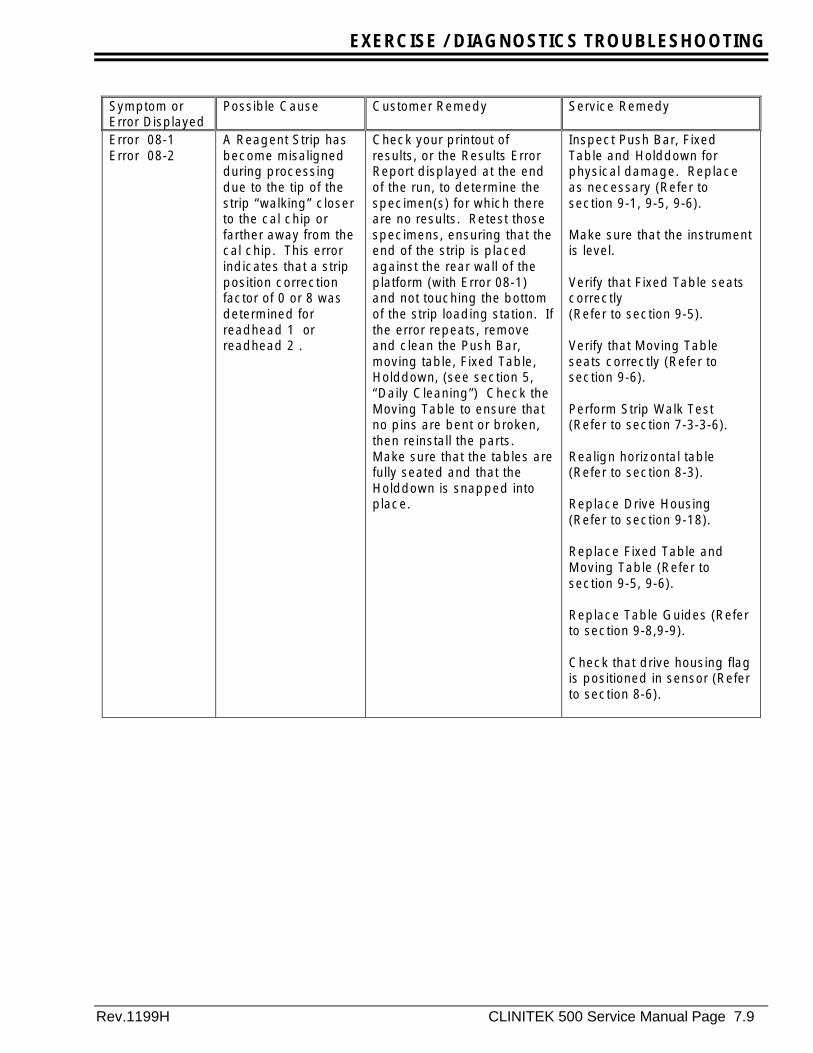
Error 08-1Error 08-2
A Reagent Strip hasbecome misalignedduring processingdue to the tip of thestrip “walking” closerto the cal chip orfarther away from thecal chip. This errorindicates that a stripposition correctionfactor of 0 or 8 wasdetermined forreadhead 1 orreadhead 2 .
Check your printout ofresults, or the Results ErrorReport displayed at the endof the run, to determine thespecimen(s) for which thereare no results. Retest thosespecimens, ensuring that theend of the strip is placedagainst the rear wall of theplatform (with Error 08-1)and not touching the bottomof the strip loading station. Ifthe error repeats, removeand clean the Push Bar,moving table, Fixed Table,Holddown, (see section 5,“Daily Cleaning”) Check theMoving Table to ensure thatno pins are bent or broken,then reinstall the parts.Make sure that the tables arefully seated and that theHolddown is snapped intoplace.
Inspect Push Bar, FixedTable and Holddown forphysical damage. Replaceas necessary (Refer tosection 9-1, 9-5, 9-6).
Make sure that the instrumentis level.
Verify that Fixed Table seatscorrectly(Refer to section 9-5).
Verify that Moving Tableseats correctly (Refer tosection 9-6).
Perform Strip Walk Test(Refer to section 7-3-3-6).
Realign horizontal table(Refer to section 8-3).
Replace Drive Housing(Refer to section 9-18).
Replace Fixed Table andMoving Table (Refer tosection 9-5, 9-6).
Replace Table Guides (Referto section 9-8,9-9).
Check that drive housing flagis positioned in sensor (Referto section 8-6).
EXERCISE / DIAGNOSTICS TROUBLESHOOTING
Page 7.10 CLINITEK 500 Service manual Rev.1199H
Symptom orError Displayed
Possible Cause Customer Remedy Service Remedy
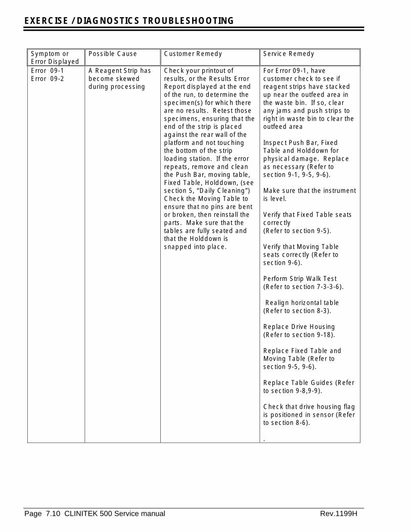
Error 09-1Error 09-2
A Reagent Strip hasbecome skewedduring processing
Check your printout ofresults, or the Results ErrorReport displayed at the endof the run, to determine thespecimen(s) for which thereare no results. Retest thosespecimens, ensuring that theend of the strip is placedagainst the rear wall of theplatform and not touchingthe bottom of the striploading station. If the errorrepeats, remove and cleanthe Push Bar, moving table,Fixed Table, Holddown, (seesection 5, “Daily Cleaning”)Check the Moving Table toensure that no pins are bentor broken, then reinstall theparts. Make sure that thetables are fully seated andthat the Holddown issnapped into place.
For Error 09-1, havecustomer check to see ifreagent strips have stackedup near the outfeed area inthe waste bin. If so, clearany jams and push strips toright in waste bin to clear theoutfeed area
Inspect Push Bar, FixedTable and Holddown forphysical damage. Replaceas necessary (Refer tosection 9-1, 9-5, 9-6).
Make sure that the instrumentis level.
Verify that Fixed Table seatscorrectly(Refer to section 9-5).
Verify that Moving Tableseats correctly (Refer tosection 9-6).
Perform Strip Walk Test(Refer to section 7-3-3-6).
Realign horizontal table(Refer to section 8-3).
Replace Drive Housing(Refer to section 9-18).
Replace Fixed Table andMoving Table (Refer tosection 9-5, 9-6).
Replace Table Guides (Referto section 9-8,9-9).
Check that drive housing flagis positioned in sensor (Referto section 8-6).
.

EXERCISE / DIAGNOSTICS TROUBLESHOOTING
Rev.1199H CLINITEK 500 Service Manual Page 7.11
Symptom orError Displayed
Possible Cause Customer Remedy Service Remedy
Error 10 –1 10 –2
Instrument opticalerror.
Turn the instrument poweroff, then remove and cleanthe Fixed Table, taking careto carefully clean thecalibration bars (see Section5, “Daily Cleaning”). Checkyour printout of results, orthe Results Error Reportdisplayed at the end of therun, to determine thespecimen(s) for which thereare no results; retest thosespecimens.
Troubleshoot Pre-ampsubassembly (Refer tosections: 7-4-1, 7-4-2, 7-3-5-1, 7-3-5-2).
Replace Pre-amp (Refer tosection 9-16-2).
Replace A/D PCB (Refer tosection 9-16-1).
Error 20-1
NOTE: Thiserror onlyapplies to Kanjiiunits.
The instrument wasnot able toautomatically detectthe strip type (if “AutoDetect” has beenselected through theSetup Routine).(Refer to section 3,Step C).
Ensure that you are using arecognized strip typeRetest the specimen using anew strip. If the errorcontinues to occur, contactyour Bayer Customer Serviceoffice.
Troubleshoot Pre-ampsubassembly (Refer tosections: 7-4-1, 7-4-2, 7-3-5-1 and 7-3-5-2).
Replace Pre-amp (Refer tosection 9-16-2).
Replace A/D PCB (Refer tosection 9-16-1).
Error 21 Internal memory error Turn the instrument poweroff, wait several seconds,then turn it back on.
Replace program card.
Replace Processor #1module(Refer to section 9-11-1).
Replace Main PCB (Refer tosection 9-11).

EXERCISE / DIAGNOSTICS TROUBLESHOOTING
Page 7.12 CLINITEK 500 Service manual Rev.1199H
Symptom orError Displayed
Possible Cause Customer Remedy Service Remedy
Error 23 Moving Table ismisaligned
Instrumentmechanical error
Turn the instrument poweroff. Check to see if themoving table is installed.Inspect the instrument forany obvious signs ofmisalignment or incorrectinstallation of the movingtable or fixed table. Removeand reinstall the fixed andmoving table, see Section 5,“Daily Cleaning.” Turn thepower back on.
Contact your BayerCustomer Service office.
Inspect Drive Housing andFixed Table Guides for wearor damage. Replace asnecessary.(Refer to section 9-5, 9-6,9-8,9-9, 9-18).
Verify that moving table isaligned correctly(Refer to section 8-3).
Verify that optical sensoroperate correctly(Refer to section 7-4-4).
Check stepper motor drivecircuits for proper operation(Refer to section 7-4-3-4).Use instrument test card tocycle motors(Refer to section 7-3-3-2 and7-3-6).
Replace Mother PCB ifdefective (Refer to section 9-13).
EXERCISE / DIAGNOSTICS TROUBLESHOOTING
Rev.1199H CLINITEK 500 Service Manual Page 7.13
Symptom orError Displayed
Possible Cause Customer Remedy Service Remedy
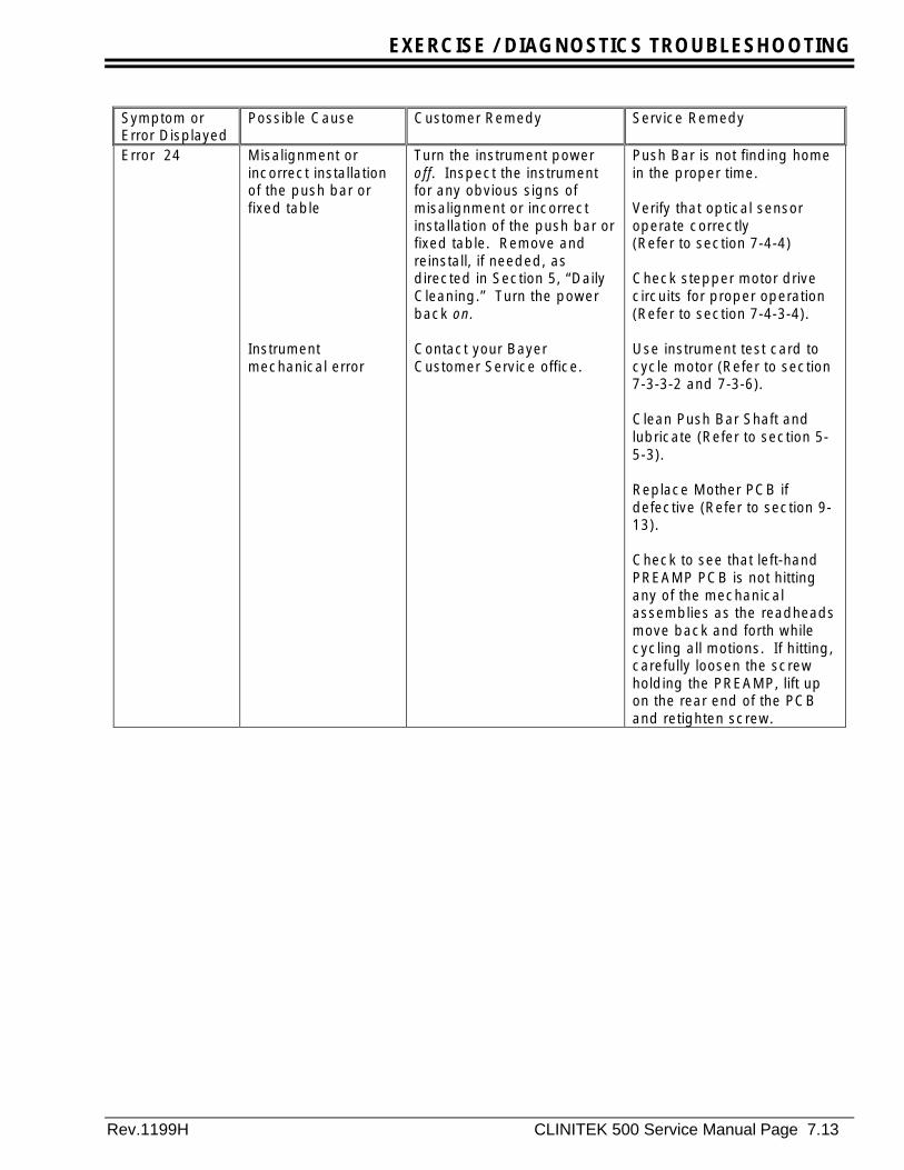
Error 24 Misalignment orincorrect installationof the push bar orfixed table
Instrumentmechanical error
Turn the instrument poweroff. Inspect the instrumentfor any obvious signs ofmisalignment or incorrectinstallation of the push bar orfixed table. Remove andreinstall, if needed, asdirected in Section 5, “DailyCleaning.” Turn the powerback on.
Contact your BayerCustomer Service office.
Push Bar is not finding homein the proper time.
Verify that optical sensoroperate correctly(Refer to section 7-4-4)
Check stepper motor drivecircuits for proper operation(Refer to section 7-4-3-4).
Use instrument test card tocycle motor (Refer to section7-3-3-2 and 7-3-6).
Clean Push Bar Shaft andlubricate (Refer to section 5-5-3).
Replace Mother PCB ifdefective (Refer to section 9-13).
Check to see that left-handPREAMP PCB is not hittingany of the mechanicalassemblies as the readheadsmove back and forth whilecycling all motions. If hitting,carefully loosen the screwholding the PREAMP, lift upon the rear end of the PCBand retighten screw.

EXERCISE / DIAGNOSTICS TROUBLESHOOTING
Page 7.14 CLINITEK 500 Service manual Rev.1199H
Symptom orError Displayed
Possible Cause Customer Remedy Service Remedy
Error 25 Readhead could notfind the Cal Chip.
Instrumentmechanical error
Turn the instrument poweroff. Inspect the instrumentfor any obvious signs ofmisalignment or incorrectinstallation of the FixedTable, or Holddown.Remove and reinstall, ifneeded, as directed inSection 5, “Daily Cleaning.”Turn the power back on.
Contact your BayerCustomer Service office.
For error 25, perform 3 on/offcycles of instrument power,ignoring any errors receivedprior to the 3rd cycle.
Check to see that left-handPREAMP PCB is not hittingany of the mechanicalassemblies as the readheadsmove back and forth. Ifhitting, carefully loosen thescrew holding the PREAMP,lift up on the rear end of thePCB and retighten screw.
Check that Flex cable is fullyseated in connector J7 onMain PCB. Insure that flexcables are fully seated in theconnectors on the PreampPCB’s and that the lampcables are locked in place onthe A/D PCB.
Verify that the lamps operate,replace if necessary.(Refer to section 7-3-5-1, 9-15)
Test Preamp operation bypositioning readheads overcal chips and obtaining A/Dcounts (Refer to section 7-3-5-2).
Replace Preamp(Refer to section 9-16-2).
Check stepper motor drivecircuits for proper operation(Refer to section 7-4-3-4).
Use instrument test card tocycle motors (Refer tosection 7-3-3-2 and 7-3-6).
Replace Mother PCB ifdefective (Refer to section 9-13).

EXERCISE / DIAGNOSTICS TROUBLESHOOTING
Rev.1199H CLINITEK 500 Service Manual Page 7.15
Symptom orError Displayed
Possible Cause Customer Remedy Service Remedy
Error 26 Fixed Table ismissing or notinstalled properly.
Install the table and platform,if missing (see Section 5,“Daily Cleaning”). If alreadyinstalled, carefully push in onthe sides of the platform tomake sure it is fullyengaged. If the errorcontinues, remove andreinstall the platform, asinstructed in Section 5.
Inspect Drive Housing andFixed Table Guides for wearor damage. Replace asnecessary (Refer to section9-5,9-6,9-8,9-9, 9-18).
Verify that all connectors areseated.
Use instrument test card totest individual sensors.(Refer to sections 7-4-4).
Confirm that the Fixed Tableenters the photo sensor onthe table guide. (refer tosection 8-5 for adjustment)
Replace sensor as necessaryMOTHER PCB defectivereplace (Refer to section 9-13).
Processor #1 is defective onthe MAIN PCB - Replace(Refer to section 9-11-1).

EXERCISE / DIAGNOSTICS TROUBLESHOOTING
Page 7.16 CLINITEK 500 Service manual Rev.1199H
Symptom orError Displayed
Possible Cause Customer Remedy Service Remedy
Error 27 Holddown isimproperlyinstalled,or missing,or is dirty.
Touch the Return toRUN/READY button ifnecessary to cancel the run.Remove the Fixed Table asinstructed in Section 5,“Daily Cleaning.” Install theHolddown if missing, orclean if it appears dirty.Reinstall the Holddown,ensuring it is properlyinstalled, then replace theplatform onto the instrument(if the Holddown appearsdamaged or discolored,replace with a newHolddown). Check yourprintout of results, or theResults Error Reportdisplayed at the end of therun, to determine thespecimen(s) for which thereare no results and retestthose specimens.
Refer to section 7-2-2-1.Inspect Fixed Table andHolddown for wear anddiscoloration. Replace asnecessary (Refer to section9-5).
Verify Readheadperformance and alignment(reference 7-3-5-3, 8-2)

EXERCISE / DIAGNOSTICS TROUBLESHOOTING
Rev.1199H CLINITEK 500 Service Manual Page 7.17
Symptom orError Displayed
Possible Cause Customer Remedy Service Remedy
Error 28 A Reagent Strip thatwas detected, asbeing placed on theplatform, was notdetected at the firstreadhead.
Moving Table is notinstalled.
A strip was never placed orwas removed after beingplaced: Check your printoutof results, or the ResultsError Report displayed at theend of the run, to determineif a result set is missing and,if so, retest the specimen.Be sure you do not placeyour hand or other objectson the strip loading station,as these can be mistaken fora Reagent Strip. If the erroroccurs repeatedly, turn theinstrument power off, waitseveral seconds, then turn itback on to recalibrate thestrip sensor.If a strip was present,remove and clean theMoving Table, Fixed Table,Holddown (Referenceoperating manual section 5,“Daily Cleaning” and“Weekly Cleaning”).
Remove the Fixed Table andcheck for the presence ofthe Moving Table. If missinginstall.
Refer to section 7-2-2-1.Confirm strip detectoroperates properly usinginstrument test card(Refer to section 7-3-3-4).
Verify that the cable comingfrom the strip detector has itsconnector properly seatedinto the mother PCB.
Replace the strip detector(Refer to section 9-14).
Check for proper readheadperformance by runningreflectance test withinstrument test card.(Refer to section 7-3-5-4)
Replace Pre-amp PCB(Refer to section 9-16-2).
EXERCISE / DIAGNOSTICS TROUBLESHOOTING
Page 7.18 CLINITEK 500 Service manual Rev.1199H
Symptom orError Displayed
Possible Cause Customer Remedy Service Remedy
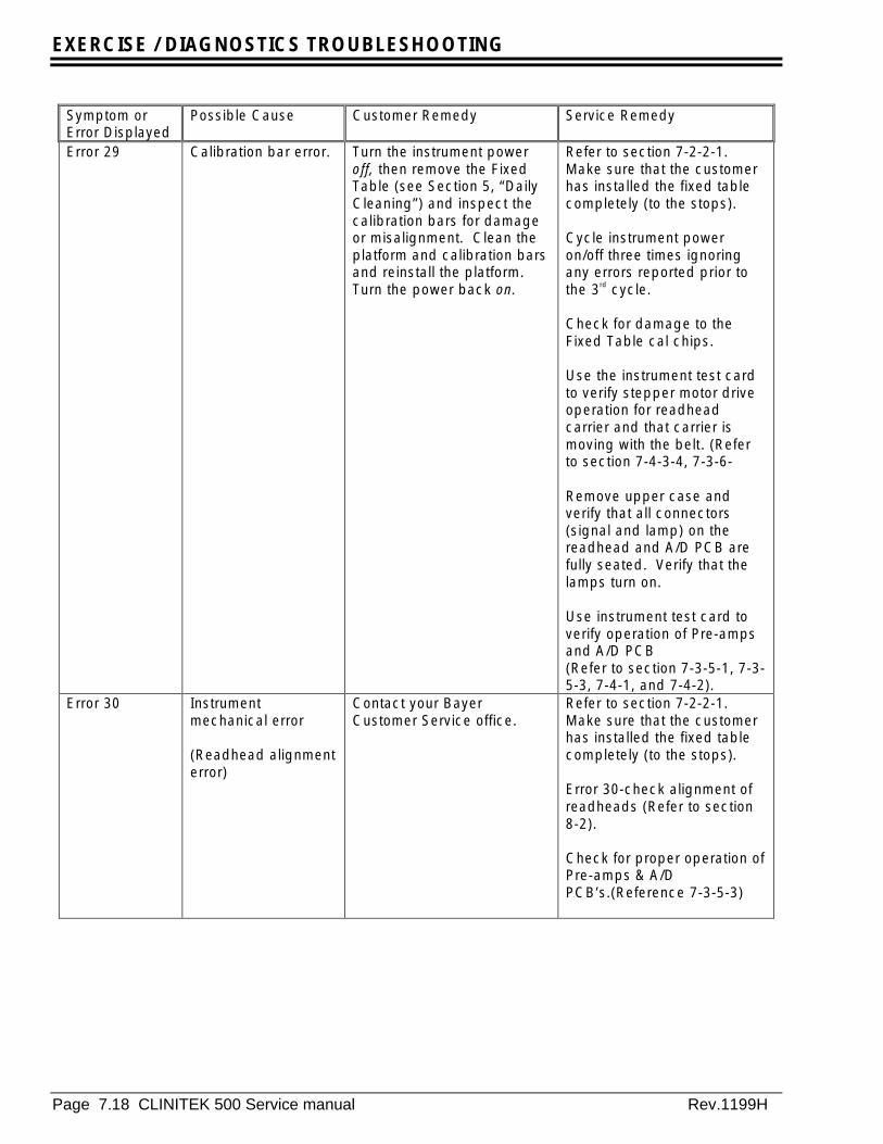
Error 29 Calibration bar error. Turn the instrument poweroff, then remove the FixedTable (see Section 5, “DailyCleaning”) and inspect thecalibration bars for damageor misalignment. Clean theplatform and calibration barsand reinstall the platform.Turn the power back on.
Refer to section 7-2-2-1.Make sure that the customerhas installed the fixed tablecompletely (to the stops).
Cycle instrument poweron/off three times ignoringany errors reported prior tothe 3rd cycle.
Check for damage to theFixed Table cal chips.
Use the instrument test cardto verify stepper motor driveoperation for readheadcarrier and that carrier ismoving with the belt. (Referto section 7-4-3-4, 7-3-6-
Remove upper case andverify that all connectors(signal and lamp) on thereadhead and A/D PCB arefully seated. Verify that thelamps turn on.
Use instrument test card toverify operation of Pre-ampsand A/D PCB(Refer to section 7-3-5-1, 7-3-5-3, 7-4-1, and 7-4-2).
Error 30 Instrumentmechanical error
(Readhead alignmenterror)
Contact your BayerCustomer Service office.
Refer to section 7-2-2-1.Make sure that the customerhas installed the fixed tablecompletely (to the stops).
Error 30-check alignment ofreadheads (Refer to section8-2).
Check for proper operation ofPre-amps & A/DPCB’s.(Reference 7-3-5-3)
EXERCISE / DIAGNOSTICS TROUBLESHOOTING
Rev.1199H CLINITEK 500 Service Manual Page 7.19
Symptom orError Displayed
Possible Cause Customer Remedy Service Remedy
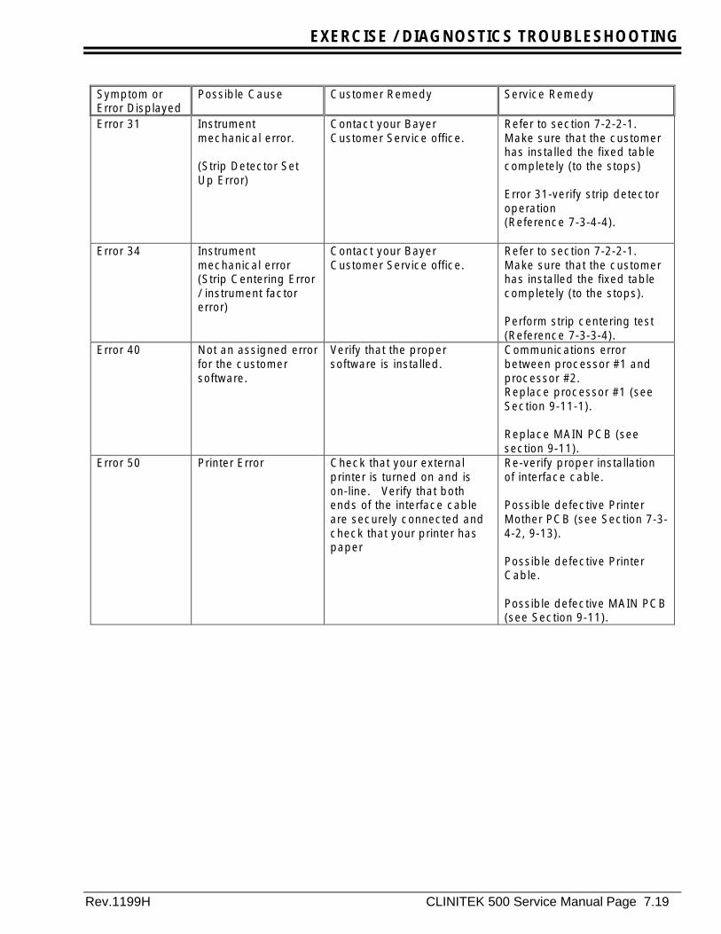
Error 31 Instrumentmechanical error.
(Strip Detector SetUp Error)
Contact your BayerCustomer Service office.
Refer to section 7-2-2-1.Make sure that the customerhas installed the fixed tablecompletely (to the stops)
Error 31-verify strip detectoroperation(Reference 7-3-4-4).
Error 34 Instrumentmechanical error(Strip Centering Error/ instrument factorerror)
Contact your BayerCustomer Service office.
Refer to section 7-2-2-1.Make sure that the customerhas installed the fixed tablecompletely (to the stops).
Perform strip centering test(Reference 7-3-3-4).
Error 40 Not an assigned errorfor the customersoftware.
Verify that the propersoftware is installed.
Communications errorbetween processor #1 andprocessor #2.Replace processor #1 (seeSection 9-11-1).
Replace MAIN PCB (seesection 9-11).
Error 50 Printer Error Check that your externalprinter is turned on and ison-line. Verify that bothends of the interface cableare securely connected andcheck that your printer haspaper
Re-verify proper installationof interface cable.
Possible defective PrinterMother PCB (see Section 7-3-4-2, 9-13).
Possible defective PrinterCable.
Possible defective MAIN PCB(see Section 9-11).
EXERCISE / DIAGNOSTICS TROUBLESHOOTING
Page 7.20 CLINITEK 500 Service manual Rev.1199H
Symptom orError Displayed
Possible Cause Customer Remedy Service Remedy
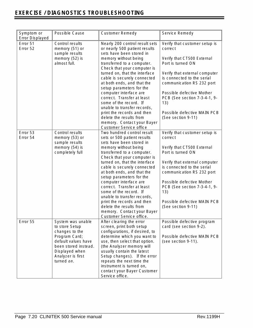
Error 51Error 52
Control resultsmemory (51) orsample resultsmemory (52) isalmost full.
Nearly 200 control result setsor nearly 500 patient resultssets have been stored inmemory without beingtransferred to a computer.Check that your computer isturned on, that the interfacecable is securely connectedat both ends, and that thesetup parameters for thecomputer interface arecorrect. Transfer at leastsome of the record. Ifunable to transfer records,print the records and thendelete the results frommemory. Contact your BayerCustomer Service office
Verify that customer setup iscorrect
Verify that CT500 ExternalPort is turned ON
Verify that external computeris connected to the serialcommunication RS 232 port
Possible defective MotherPCB (See section 7-3-4-1, 9-13)
Possible defective MAIN PCB(See section 9-11)
Error 53Error 54
Control resultsmemory (53) orsample resultsmemory (54) iscompletely full
Two hundred control resultsets or 500 patient resultssets have been stored inmemory without beingtransferred to a computer.Check that your computer isturned on, that the interfacecable is securely connectedat both ends, and that thesetup parameters for thecomputer interface arecorrect. Transfer at leastsome of the record. Ifunable to transfer records,print the records and thendelete the results frommemory. Contact your BayerCustomer Service office.
Verify that customer setup iscorrect
Verify that CT500 ExternalPort is turned ON
Verify that external computeris connected to the serialcommunication RS 232 port
Possible defective MotherPCB (See section 7-3-4-1, 9-13)
Possible defective MAIN PCB(See section 9-11)
Error 55 System was unableto store Setupchanges to theProgram Card;default values havebeen stored instead.Displayed whenAnalyzer is firstturned on.
After clearing the errorscreen, print both setupconfigurations, if desired, todetermine which you want touse, then select that option.(the Analyzer memory willusually contain the latestSetup changes). If the errorrepeats the next time theinstrument is turned on,contact your Bayer CustomerService office.
Possible defective programcard (see section 9-2).
Possible defective MAIN PCB(see section 9-11).
EXERCISE / DIAGNOSTICS TROUBLESHOOTING
Rev.1199H CLINITEK 500 Service Manual Page 7.21
Symptom orError Displayed
Possible Cause Customer Remedy Service Remedy
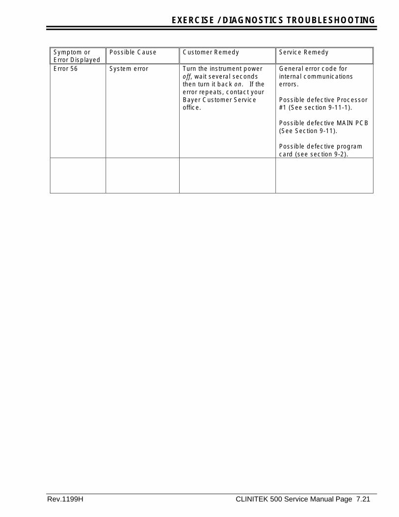
Error 56 System error Turn the instrument poweroff, wait several secondsthen turn it back on. If theerror repeats, contact yourBayer Customer Serviceoffice.
General error code forinternal communicationserrors.
Possible defective Processor#1 (See section 9-11-1).
Possible defective MAIN PCB(See Section 9-11).
Possible defective programcard (see section 9-2).

EXERCISE / DIAGNOSTICS TROUBLESHOOTING
Page 7.22 CLINITEK 500 Service manual Rev 1299H
Is the DisplayBlank?
Trouble shoot per servicemanual.
Report error: DT001
Is character stringcorrect?Do adjacent areas
around the keysrespond?
Cycle power andrecalibrate touch
screen.Does this correct
Cycle Power. Does touchscreen respond?
Report Error:DT008
Cycle power andrecalibrate touch
screen.Does touch screen
Report Error:DT009
Is Pusher Bar to the left?Trouble shoot PerService Manual
Report Error: DT010
Will strip detectordetect strip and cycle
pusher bar
System Locked upReport Error: DT012
Does the Displayupdate to run mode
Report Error:DT013
Replace touch ScreenReport Error: DT014
Does Data Print
Is display operatingcorrectly?
Are lines scrollingon the screen? Display Bad
Report Error: DT002
Is touch screenresponding?
No problem
No problem
Cycle power. Doesthe problem correct
itself?
Trouble shootDisplay, Main
PCB andProgram Card.
Report Error:DT005
Problem correctedReport error: DT003
Report ErrorDT007
Report Error:DT006
Perform the following
1) Reset memory withInstrument test card.
2) Reset the customersettings to theinstrument defaults.
Is the problem corrected?
Problem correctedReport Error: DT004
Trouble shoot PerService Manual
Report Error: DT011
YES
NO
YES
YES
YES
YES
NO
YES
YES
YES
YES
YES
YES
YES
NO
NO
NO
NO
NO
NO
NO
NO
YES
YES
NO
NO
YES
NO
NO
NO
Perform the following
1) Print out instrument setup.
2) Reset the customersettings to theinstrument defaults
NO
ReportError:DT015
YES
Failure Identification Flow Chart For Display and Touch Screen Problems
Figure 7-1-1 top of chapter
EXERCISE / DIAGNOSTICS TROUBLESHOOTING
Rev 1199H CLINITEK 500 Service Manual Page 7.23
7-2 Explanation of Error Codes
7-2-1 Error Handling
The Errors on the instrument are divided into:1) General Errors2) Data Set Errors.
A General Error is defined as an error resultingfrom hardware input, e.g., a ROM checksumError, RAM checksum error, Processor #2programming error or a sensor error. Theseerrors are detected by processor #2.
A Data Set Error is defined as an errordetected by analyzing the data collected fromthe readheads during the read process.
7-2-1-2 Error Number Display
The Instrument Test Card and Customer Carddisplay only those errors defined as "generalerrors" on the screen. These general errors aregenerated by processor #2 as a two-digitnumber and sent to processor #1 to display onthe screen (refer to Table 7-2-1 for completelisting).
7-2-1-3 Error Numbers Printed
The Data Set errors are printed or sent with thedata sets. The Data Set errors are displayed indifferent forms depending upon if anInstrument Test Card is being used or theCustomer Card. When the Customer Card isinstalled in the instrument, the error code willbe printed or displayed on the screen ( seefigure 7-2-1) as 1-xx or 2-xx. The first digit
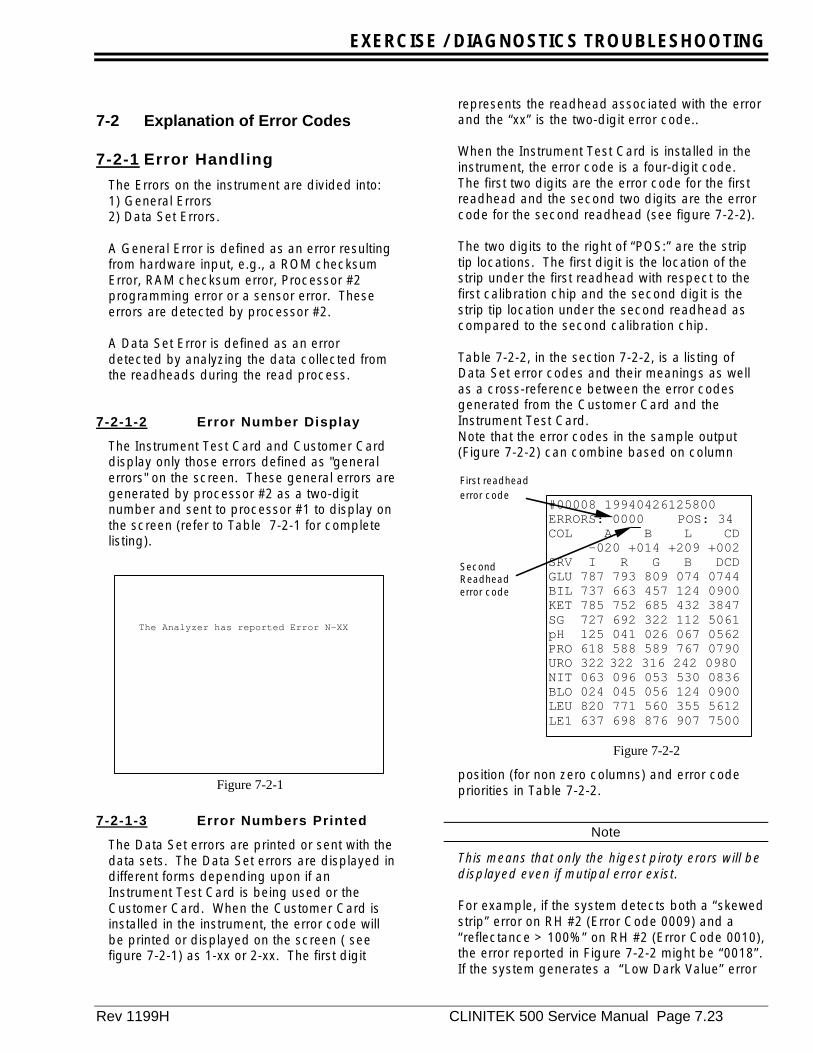
represents the readhead associated with the errorand the “xx” is the two-digit error code..
When the Instrument Test Card is installed in theinstrument, the error code is a four-digit code.The first two digits are the error code for the firstreadhead and the second two digits are the errorcode for the second readhead (see figure 7-2-2).
The two digits to the right of “POS:” are the striptip locations. The first digit is the location of thestrip under the first readhead with respect to thefirst calibration chip and the second digit is thestrip tip location under the second readhead ascompared to the second calibration chip.
Table 7-2-2, in the section 7-2-2, is a listing ofData Set error codes and their meanings as wellas a cross-reference between the error codesgenerated from the Customer Card and theInstrument Test Card.Note that the error codes in the sample output(Figure 7-2-2) can combine based on column
position (for non zero columns) and error codepriorities in Table 7-2-2.
Note
This means that only the higest piroty erors will bedisplayed even if mutipal error exist.
For example, if the system detects both a “skewedstrip” error on RH #2 (Error Code 0009) and a“reflectance > 100%” on RH #2 (Error Code 0010),the error reported in Figure 7-2-2 might be “0018”.If the system generates a “Low Dark Value” error
The Analyzer has reported Error N-XX
Figure 7-2-1
#00008 19940426125800ERRORS: 0000 POS: 34COL A B L CD -020 +014 +209 +002SRV I R G B DCDGLU 787 793 809 074 0744BIL 737 663 457 124 0900KET 785 752 685 432 3847SG 727 692 322 112 5061pH 125 041 026 067 0562PRO 618 588 589 767 0790URO 322 322 316 242 0980NIT 063 096 053 530 0836BLO 024 045 056 124 0900LEU 820 771 560 355 5612LE1 637 698 876 907 7500
First readheaderror code
SecondReadheaderror code
Figure 7-2-2

EXERCISE / DIAGNOSTICS TROUBLESHOOTING
Page 7.24 CLINITEK 500 Service Manual Rev. 1199H
for RH #1 (Error Code 0100) and a “MissingStrip” error for RH #2 (Error Code 0006) thenthe error code output would be “0106”.However, if the system generates two errorswith digits in the same column only the higherpriority error is displayed. For example, a“Reflectance > 100%” error on RH #1 (ErrorCode 1000) and a “Auto Strip Type Error” onRH #1 (Error Code 2000), then the system willoutput Error Code “2000” since the Auto StripType error (Priority = 10) is a higher priorityerror then Reflectance (Priority = 11).

EXERCISE / DIAGNOSTICS TROUBLESHOOTING
Rev 1199H CLINITEK 500 Service Manual Page 7.25
7-2-2 Error Summary
General Error Codes
Instrument Test Card Error DefinitionError CodeGenerated
Customer Card Error Definition
ROM Checksum Error 21 ROM Checksum ErrorTable Movement Error *23 Table Movement ErrorPush Bar Movement Error *24 Push Bar Movement ErrorRead-head Scan Movement Error *25 Read-head Scan Movement ErrorTable Not in Place 26 Table Not in PlaceHold-downs Not in Place *27 Hold-downs Not in PlaceFalse Strip Detect *28 False Strip DetectCal Chip NOT Found Error 29 Cal Chip NOT Found ErrorRead-head Alignment Error *30 Read-head Alignment ErrorStrip Detector Setup Error 31 Strip Detector Setup Error
(unassigned) 32 (unassigned)(unassigned) 33 (unassigned)
Strip Centering Error 34 Strip Centering ErrorCommunication 40 (unassigned)
(unassigned) 50 Printer error(unassigned) 51 Control results memory is almost full(unassigned) 52 Sample results memory is almost full(unassigned) 53 Control results memory is completely full(unassigned) 54 Sample results memory is completely full(unassigned) 55 System was unable to store Setup
changes in program card
(unassigned) 56 System error
**Special Instrument Release TestData Set Errors
61 thru 93
Notes: *Indicates that these error are checked for and reported only during a run** Refer to table 7-2-2-1 Refer to section 7-3 Trouble shooting guide for corrective actions
Table 7-2-1

EXERCISE / DIAGNOSTICS TROUBLESHOOTING
Page 7.26 CLINITEK 500 Service Manual Rev. 1199H
7-2-2-1 General Errors
ROM Checksum Error (21)
If the calculated checksum for the ROM doesnot equal 0, then this error is set.
Table Movement Error (23)
The table sensor is checked for "no sensor" at2.5 seconds into the cycle when the table flagshould not interrupt the optical sensor and againafter 3.0 seconds in the cycle for "sensorpresent" when the table flag should interrupt theoptical sensor. If either condition fails, the erroris set.
Push Bar Movement error (24)
The push bar sensor is checked for "no sensor"at about 2.5 seconds in the cycle if the Push Barwas to move and again at about 3.8 secondswhen it should be at the sensor. If eithercondition fails, the error is set.
Readhead Scan Movement Error (25)
This error is set in RUN, during readheadposition initialization, when the readhead is notpositioned on the cal chip as it should be.
Table Not In Place (26)
The table sensor is not activated.
Holddowns Not In Place (27)
When a strip is read at the first readhead, thereflectance between pads 10 and 11 is checked( this is actually between the tip of the strip andthe calibration chip). If no reflectance readingis below 40%, the error condition is set. (Withthe hold-downs in place the reflectance is onthe order of 15% to 20% and with no hold-downs it is above 80%).
False Strip Detect (28)
If a strip is detected and verified by the stripdetector but is not sensed as being present atthe 1st readhead when it should be, this error isset. A strip is sensed as being present asfollows: Two areas of the strip are checked,between pads 2 and 3 and between pads 9 and10.. If both areas did NOT have a reading>65%, the false strip detect error is set.
Cal Chip NOT found error (29)
During initialization of the readhead position, eitherat power ON or during RUN, the cal chip underreadhead 1 could not be found (IR reflectance<50%) by moving IN up to 750 steps.
Read-head Alignment error (30)
The stored IR readings for each readhead aretested starting with the 1st IR reading in the readbuffer, which is near the cal chip center. The calchip edge is, defined as the first reading below50% reflectance and the number of motor stepscounted. The postion of the cal chip edge forreadhead 2 is compared to that of readhead 1. Ifreadhead 2 varies more than ± 3 motor steps thenthis error is set.
NOTE:
During the strip read operation, readings arestored beginning with position 10 (10 motorsteps out from the cal position) and acomplete set of readings is stored every foursteps thereafter or every 0.01716".
Strip Detector Setup error (31)
When the strip detector "detection level circuit" iscalibrated, if the level count was not between 10and 254, inclusive, this error is set. A high countindicates that there was too much light reflectingfrom the table or that there was a circuitmalfunction..
Instrument Factor / Strip Centering error(34)
This error is generated when the 2-digit StripCentering step factor is not within the range of 04to 40 for either readhead or if the differencebetween the factor for each readhead is greaterthan 10.
Internal Communications Error (40)
An error occurred in the communication betweenthe two processors
EXERCISE / DIAGNOSTICS TROUBLESHOOTING
Rev 1199H CLINITEK 500 Service Manual Page 7.27
NOTE:
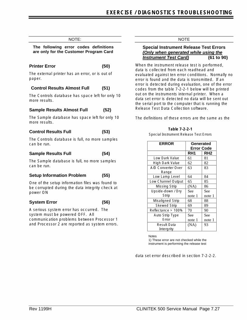
The following error codes definitionsare only for the Customer Program Card
Printer Error (50)
The external printer has an error, or is out ofpaper.
Control Results Almost Full (51)
The Controls database has space left for only 10more results. Sample Results Almost Full (52)
The Sample database has space left for only 10more results.
Control Results Full (53)
The Controls database is full, no more samplescan be run.
Sample Results Full (54)
The Sample database is full, no more samplescan be run.
Setup Information Problem (55)
One of the setup information files was found tobe corrupted during the data integrity check atpower ON
System Error (56)
A serious system error has occurred. Thesystem must be powered OFF. Allcommunication problems between Processor 1and Processor 2 are reported as system errors.
NOTE
Special Instrument Release Test Errors(Only when generated while using theInstrument Test Card) (61 to 90)
When the instrument release test is performed,data is collected from each readhead andevaluated against ten error conditions. Normally noerror is found and the data is transmitted. If anerror is detected during evaluation, one of the errorcodes from the table 7-2-2-1 below will be printedout on the instruments internal printer. When adata set error is detected no data will be sent outthe serial port to the computer that is running theRelease Test Data Collection software.
The definitions of these errors are the same as the
data set error described in section 7-2-2-2.
ERROR GeneratedError Code
RH1 RH2Low Dark Value 61 81High Dark Value 62 82
A/D Converter OverRange
63 83
Low Lamp Level 64 84Low Channel Output 65 85
Missing Strip (NA) 86Upside-down / Dry
StripSeenote 1
Seenote 1
Misaligned Strip 68 88Skewed Strip 69 89
Reflectance > 100% 70 90Auto Strip Type
ErrorSeenote 1
Seenote 1
Result DataIntergrity
(NA) 93
Notes1) These error are not checked while theinstrument is performing the release test
Table 7-2-2-1Special Instrument Release Test Errors
EXERCISE / DIAGNOSTICS TROUBLESHOOTING
Page 7.28 CLINITEK 500 Service Manual Rev. 1199H
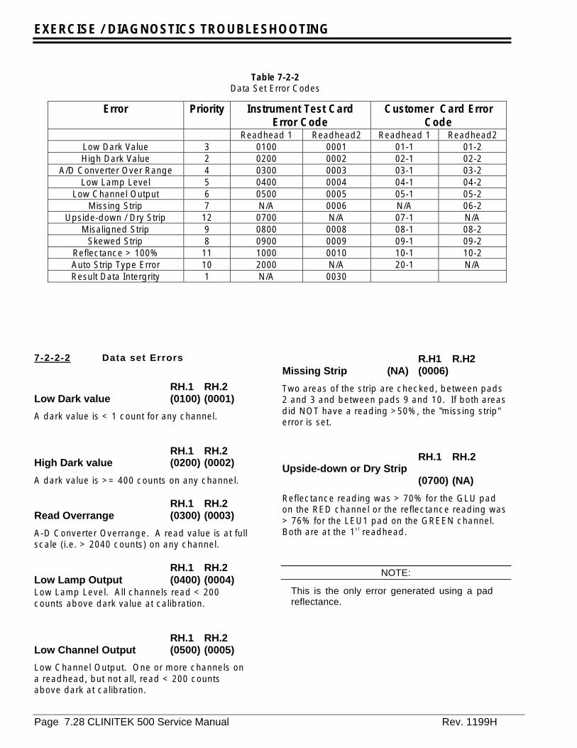
7-2-2-2 Data set Errors
RH.1 RH.2Low Dark value (0100) (0001)
A dark value is < 1 count for any channel.
RH.1 RH.2High Dark value (0200) (0002)
A dark value is >= 400 counts on any channel.
RH.1 RH.2Read Overrange (0300) (0003)
A-D Converter Overrange. A read value is at fullscale (i.e. > 2040 counts) on any channel.
RH.1 RH.2Low Lamp Output (0400) (0004)Low Lamp Level. All channels read < 200counts above dark value at calibration.
RH.1 RH.2Low Channel Output (0500) (0005)
Low Channel Output. One or more channels ona readhead, but not all, read < 200 countsabove dark at calibration.
R.H1 R.H2Missing Strip (NA) (0006)
Two areas of the strip are checked, between pads2 and 3 and between pads 9 and 10. If both areasdid NOT have a reading >50%, the "missing strip"error is set.
RH.1 RH.2Upside-down or Dry Strip
(0700) (NA)
Reflectance reading was > 70% for the GLU padon the RED channel or the reflectance reading was> 76% for the LEU1 pad on the GREEN channel.Both are at the 1st readhead.
NOTE:
This is the only error generated using a padreflectance.
Data Set Error Codes
Error Priority Instrument Test CardError Code
Customer Card ErrorCode
Readhead 1 Readhead2 Readhead 1 Readhead2Low Dark Value 3 0100 0001 01-1 01-2High Dark Value 2 0200 0002 02-1 02-2
A/D Converter Over Range 4 0300 0003 03-1 03-2Low Lamp Level 5 0400 0004 04-1 04-2
Low Channel Output 6 0500 0005 05-1 05-2Missing Strip 7 N/A 0006 N/A 06-2
Upside-down / Dry Strip 12 0700 N/A 07-1 N/AMisaligned Strip 9 0800 0008 08-1 08-2
Skewed Strip 8 0900 0009 09-1 09-2Reflectance > 100% 11 1000 0010 10-1 10-2Auto Strip Type Error 10 2000 N/A 20-1 N/AResult Data Intergrity 1 N/A 0030
Table 7-2-2Data Set Error Codes

EXERCISE / DIAGNOSTICS TROUBLESHOOTING
Rev 1199H CLINITEK 500 Service Manual Page 7.29
RH.1 RH.2Misaligned Strip (0800) (0008)
When doing the strip position correction, theend of the strip nearest the cal chip is locatedby finding the position where the reflectancegoes above 30% as the readhead moves towardthe front of the instrument. Steps are countedand a number of "0" through "8" is assignedindicating relative position for each readhead.A number "4" is the nominal position where thestrip is in perfect alignment. A smaller numberindicates the strip is closer to the cal chip, alarger number shows it is farther. If the numberis "0" or "8", the error code for that readhead isset. The positions "1" through "7" will result incorrect reflectance for the strip. Each digitindicates a shift of 0.01716 inchs so that correctreadings will be obtained for shifts of±0.051 inchs
RH.1 RH.2Skewed Strip (0900) (0009)
The reflectance in the areas between pads 2and 3 and between pads 9 and 10 are scannedthrough 8 step positions. If a reflectance is>65% at one area but <65% in the other area,this error is set.
RH.1 RH.2Reflectance >100% (1000) (0010)
The reflectance for any pad on the stripmeasures more than 100%. This may be due toa bad calibration value.
RH.1 RH.2Auto Strip Type error (2000) (NA)
If the strip type is set to Japan Auto Strip, then thestrip type being used is determined by checkingfor the GLU pad (reflectance <55%) at one of thetwo positions for the two supported strip types -MULTISTIX 10 SG and URO-HEMACOMBISTIX SGL. If neither of these were <55%, this error is set.This error code is also reported when a test RUNhas commenced with one reagent strip type and adifferent reagent strip type is detected during theRUN. Although the CT500 supports the auto-detection of the MULTISTIX 10 SG reagent stripand the URO-HEMACOMBISTIX SG L reagent strip,the CT500 does not supporting “mixing” these striptypes during a RUN. A RUN may only consist ofone reagent strip type.
RH.1 RH.2Result Data Integrity (NA) (0030)
The integrity of the results data can not beguaranteed. The checksum sent by Processor 2did not match the checksum calculated byProcessor 1. top of chapter
EXERCISE / DIAGNOSTICS TROUBLESHOOTING
Page 7.30 CLINITEK 500 Service Manual Rev. 1199H

EXERCISE / DIAGNOSTICS TROUBLESHOOTING
Rev.1199H CLINITEK 500 Service Manual Page 7.31
7-3 Explanation of Instrument TestCard
7-3-0 Introduction
The Instrument Test Card is a special programcard used during the manufacturing andservicing of the CLINITEK® 500. The followingsection of the manual explains the function ofeach test.
To use this test card, first turn theinstrument power off, then remove the CustomerProgram Card (all customer setup options aresaved in this card). Next, insert the test card intothe program card socket. When the instrumentpower is turned back ON, the test software willstart.
Following the startup screen if the touch sscreenis not calibrated, the user will be prompted tocalibrate the touch screen by pressing the areasindicated on the following screens.
+ TOUCH SCREEN HERE
CALIBRATE THE TOUCH SCREEN
CALIBRATE THE TOUCH SCREEN
TOUCH SCREEN HERE +
CLINITEK 500
INSTRUMENT TEST PROGRAM
Copyright 1997 Bayer Corporation
Power ON message:

EXERCISE / DIAGNOSTICS TROUBLESHOOTING
Page 7.32 CLINITEK 500 Service Manual Rev. 1199H
When the program card is first installed, theinstrument compares the software version in inthe card for processor 2 with that runningprocessor 2. If the software versions do notmatch, the two version numbers will be displayedand the system will prompt “ ReprogramProcessor #2”. Pushing the “YES” key on thetouch screen reprograms the processor whilepushing the “NO” key does not.
AAAAA: Represents the version o processor #2software being used by the instrument.
BBBBB: Represents the version of processor #2software on the PCMCIA card.
Processor #2 version is: AAAAAA The new card version is: BBBBBB Reprogram Processor #2?
YES
NO
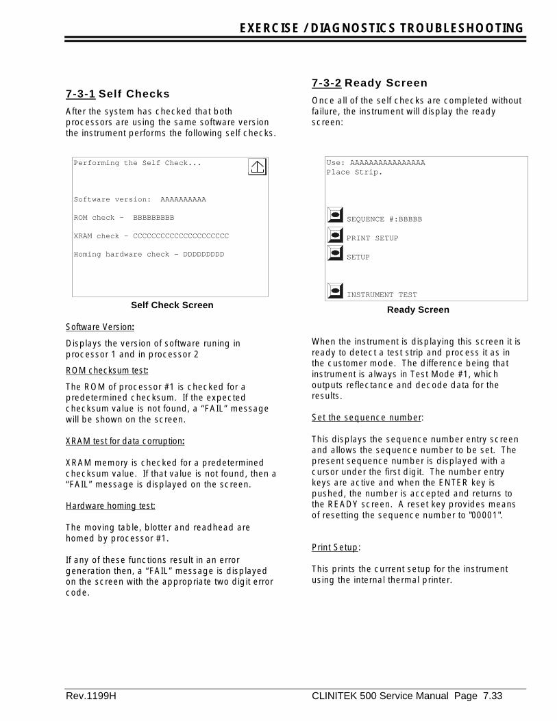
EXERCISE / DIAGNOSTICS TROUBLESHOOTING
Rev.1199H CLINITEK 500 Service Manual Page 7.33
7-3-1 Self Checks
After the system has checked that bothprocessors are using the same software versionthe instrument performs the following self checks.
Self Check Screen
Software Version:
Displays the version of software runing inprocessor 1 and in processor 2
ROM checksum test:
The ROM of processor #1 is checked for apredetermined checksum. If the expectedchecksum value is not found, a “FAIL” messagewill be shown on the screen.
XRAM test for data corruption:
XRAM memory is checked for a predeterminedchecksum value. If that value is not found, then a“FAIL” message is displayed on the screen.
Hardware homing test:
The moving table, blotter and readhead arehomed by processor #1.
If any of these functions result in an errorgeneration then, a “FAIL” message is displayedon the screen with the appropriate two digit errorcode.
7-3-2 Ready Screen
Once all of the self checks are completed withoutfailure, the instrument will display the readyscreen:
Ready Screen
When the instrument is displaying this screen it isready to detect a test strip and process it as inthe customer mode. The difference being thatinstrument is always in Test Mode #1, whichoutputs reflectance and decode data for theresults.
Set the sequence number:
This displays the sequence number entry screenand allows the sequence number to be set. Thepresent sequence number is displayed with acursor under the first digit. The number entrykeys are active and when the ENTER key ispushed, the number is accepted and returns tothe READY screen. A reset key provides meansof resetting the sequence number to "00001".
Print Setup:
This prints the current setup for the instrumentusing the internal thermal printer.
Use: AAAAAAAAAAAAAAAAPlace Strip.
SEQUENCE #:BBBBB
PRINT SETUP
SETUP
INSTRUMENT TEST
Performing the Self Check...
Software version: AAAAAAAAAA
ROM check - BBBBBBBBB
XRAM check - CCCCCCCCCCCCCCCCCCCCC
Homing hardware check - DDDDDDDDD

EXERCISE / DIAGNOSTICS TROUBLESHOOTING
Page 7.34 CLINITEK 500 Service Manual Rev. 1199H
Setup:
Selecting this option presents a new screen thatdisplays the functions that can be set.
Setup sub-menu
Set the Date:
This selection allows the date to be set.
Set the Time:
Selecting this key allows the time to be set.
Clear Memory:
If this selection is chosen, the following displaywill appear:
Yes:
If this is selected all test results stored in thesystem are purged.
Reset System Memory:
If selected the fixed memory locations are reset todefault values. This must be performed afterusing the instrument Test Card before installingthe customer card.
Printer:
This key toggles the internal printer on or off. Thedefault setting is ON.
Strip Type:
This option allows the user to select what type ofreagent strip will be used. MULTISTIX 10 SG isthe default strip.
7-3-3 Instrument Tests
The diagnostic tests provided by the InstrumentTest Card are grouped in 4 levels or sub menus.Each level of test is displayed as a separatemenu on the display
• Level 1 tests all complete subsystem tests.
• Level 2 tests are interface tests.
• Level 3 tests are all related to data collection.
• Level 4 tests operations which are specific toprocessor 1.
SELECT ITEM TO SPECIFY ITSOPTION
Set the Date AA-BB-CC (M-D-Y)
Set the Time DD:EE (24 hr)
Clear Memory
Printer: FFF
Strip Type: GGGGGGGGGGGGGGGGG
Clear all results from the CLINITEK memory ? Are you sure ?
YES
NO
Reset System Memory
Setup sub-menu Clear Memory Screen
Instrument Tests, Level 1
INSTRUMENT RELEASE TEST
EXERCISE ALL MOTIONS
SENSOR STATUS
SETUP STRIP CENTERINGREBOOT
STRIP WALK TEST SYSTEM
LEVEL 2 TESTS
Instrument Test Level 1 Screen

EXERCISE / DIAGNOSTICS TROUBLESHOOTING
Rev.1199H CLINITEK 500 Service Manual Page 7.35
7-3-3-1 Instrument Release Test
Equipment Required:
• PC with the following minimumconfiguration:486 33MHz processor, 8 (16)Megabytes of Memory, 1 free serial port
• Windows 3.11 or 95• Serial test cable (Null modem DB25 to DB9)
(p/n 40453255)• Instrument Release Test Software
(p/n SR00169X)• Release Test limits file (p/n SR00170X)• Floating Rail Hold-down (p/n 71647013)• Hard Standards Test Strip (p/n 95002262)• Thermal Printer Paper• Instrument Test Card (p/n SR00081X)• Refer to the RSL 024E6470 (Recommended
Spare Parts List) for the current part numbersfor the fixtures
The Instrument Release Test uses a special teststrip and a PC running the Release test softwareto perform a quality check on the operation of theinstrument. In this test, data is outputed fromthe instrument and col lected by the PCrunning the release software. Next, the data isanalyzed and compared to predefined limits, andif the results are within the limits, the instrumentpasses the test. The PC screen will display if theinstrument passed or failed.
The Test Hard Standard strip used for the releasetest has pads in the following positions P4, P9,P10 and P11.
The procedure for performing the Release Test isas follows:
1. With the power off install the Instrument TestCard and connect the CT 500 via the DB25serial port to the test cable from the PC.Install the Floating Rail Hold-down on theFixed Table and install the Fixed Table on theinstrument
2. Turn the CLINITEK® 500 “ON” and select theRelease Test from the menu.
3. Place the test strip onto the reagent loadarea of the fixed table and push "OK" button.
4. The instrument moves the strip to the firstreadhead and scans the strip 10 times, doingthe normal positioning, calibration, andreadhead movement. Only the reflectanceresults are saved to be outputed.
5. Calibration is performed on the firstcalibration chip. During the calibration, thereflectances, light counts, and dark countsare stored. Following calibration 29reflectance reading are taken and stored.
6. The results from the first readhead are storedas sequence number 001.
7. The strip is moved as quickly as possible tothe second readhead and steps 3 and 4 arerepeated and stored as sequence number002.
8. The results are available after the strip is readat the second readhead and will be outputedwhen asked for by a connected computer.
9. If the test is repeated, any results from aprevious test are overwritten.
10. The results may be printed also if desired.
NOTE
The full Service Release Procedure isdetailed in chapter 12
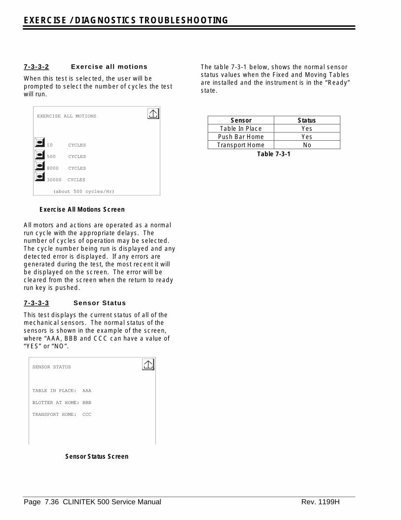
EXERCISE / DIAGNOSTICS TROUBLESHOOTING
Page 7.36 CLINITEK 500 Service Manual Rev. 1199H
7-3-3-2 Exercise all motions
When this test is selected, the user will beprompted to select the number of cycles the testwill run.
Exercise All Motions Screen
All motors and actions are operated as a normalrun cycle with the appropriate delays. Thenumber of cycles of operation may be selected.The cycle number being run is displayed and anydetected error is displayed. If any errors aregenerated during the test, the most recent it willbe displayed on the screen. The error will becleared from the screen when the return to readyrun key is pushed.
7-3-3-3 Sensor Status
This test displays the current status of all of themechanical sensors. The normal status of thesensors is shown in the example of the screen,where “AAA, BBB and CCC can have a value of“YES” or “NO”.
The table 7-3-1 below, shows the normal sensorstatus values when the Fixed and Moving Tablesare installed and the instrument is in the “Ready”state.
EXERCISE ALL MOTIONS
10 CYCLES
500 CYCLES
8000 CYCLES
30000 CYCLES
(about 500 cycles/Hr)
SENSOR STATUS
TABLE IN PLACE: AAA
BLOTTER AT HOME: BBB
TRANSPORT HOME: CCC
Sensor Status Screen
Sensor StatusTable In Place Yes
Push Bar Home YesTransport Home No
Table 7-3-1
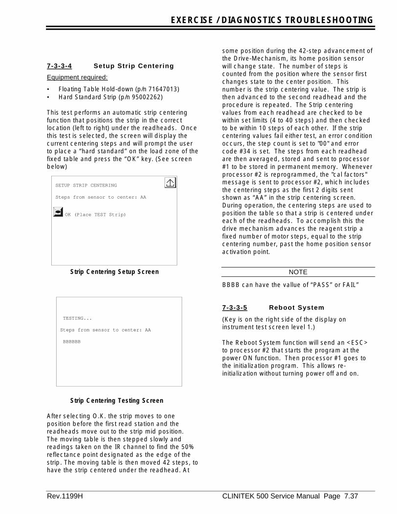
EXERCISE / DIAGNOSTICS TROUBLESHOOTING
Rev.1199H CLINITEK 500 Service Manual Page 7.37
7-3-3-4 Setup Strip Centering
Equipment required:
• Floating Table Hold-down (p/n 71647013)• Hard Standard Strip (p/n 95002262)
This test performs an automatic strip centeringfunction that positions the strip in the correctlocation (left to right) under the readheads. Oncethis test is selected, the screen will display thecurrent centering steps and will prompt the userto place a “hard standard” on the load zone of thefixed table and press the “OK” key. (See screenbelow)
Strip Centering Setup Screen
Strip Centering Testing Screen
After selecting O.K. the strip moves to oneposition before the first read station and thereadheads move out to the strip mid position.The moving table is then stepped slowly andreadings taken on the IR channel to find the 50%reflectance point designated as the edge of thestrip. The moving table is then moved 42 steps, tohave the strip centered under the readhead. At
some position during the 42-step advancement ofthe Drive-Mechanism, its home position sensorwill change state. The number of steps iscounted from the position where the sensor firstchanges state to the center position. Thisnumber is the strip centering value. The strip isthen advanced to the second readhead and theprocedure is repeated. The Strip centeringvalues from each readhead are checked to bewithin set limits (4 to 40 steps) and then checkedto be within 10 steps of each other. If the stripcentering values fail either test, an error conditionoccurs, the step count is set to "00" and errorcode #34 is set. The steps from each readheadare then averaged, stored and sent to processor#1 to be stored in permanent memory. Wheneverprocessor #2 is reprogrammed, the "cal factors"message is sent to processor #2, which includesthe centering steps as the first 2 digits sentshown as “AA” in the strip centering screen.During operation, the centering steps are used toposition the table so that a strip is centered undereach of the readheads. To accomplish this thedrive mechanism advances the reagent strip afixed number of motor steps, equal to the stripcentering number, past the home position sensoractivation point.
NOTE
BBBB can have the vallue of “PASS” or FAIL”
7-3-3-5 Reboot System
(Key is on the right side of the display oninstrument test screen level 1.)
The Reboot System function will send an <ESC>to processor #2 that starts the program at thepower ON function. Then processor #1 goes tothe initialization program. This allows re-initialization without turning power off and on.
SETUP STRIP CENTERING
Steps from sensor to center: AA
OK (Place TEST Strip)
TESTING...
Steps from sensor to center: AA
BBBBBB

EXERCISE / DIAGNOSTICS TROUBLESHOOTING
Page 7.38 CLINITEK 500 Service Manual Rev. 1199H
7-3-3-6 Strip Walk Test
Equipment Required:
Normal hold down10 MULTISTIX-10SG reagent strips
When this test is selected, the instrumentprompts the user to prepare to load 10“Dry”strips, one at a time, on to the load zone ofthe fixed table. Once the “O.K.” key is pressed,the instrument starts the test, as each strip isplaced on the load zone of the fixed table thepusher arm is activated and moves the strip tothe moving table.
Strip Walk Setup
Strip Walk Testing
As the strips are moved under each readhead,the strip tip is located with respect to eachCalibration Bar and stored in memory. After allten strips have had the tip locations determinedby both readheads the data is analyzed. A printout of the data and test results is printed out onthe internal printer (see figure 7-3-1).
The first line of data printed is location of each ofthe ten strips read under Readhead 1 (RH1). Thesecond line of data printed is location of each ofthe ten strips read under Readhead 2 (RH2).These measurements (in motor steps) can rangebetween "0" and "8", with "4" being ideal.
A number lower than "4" indicates that the tip ofthe strip is closer to the calibration bar.
A number greater than "4" indicates that the tip ofthe strip is further away from the calibration bar.
The next two lines are the average position valuesfor the ten strip readings taken under eachreadhead, “RH1 Ave.” and “RH2 Ave.”
The last line which is printed “Strip Walk Test = X“ where “X” can be equal to one of three values,A, B or C. These values represent different setsof criteria, which the assembly passes
C = A strip position of “0” or “8” wasdetected at either readhead
B = A strip position of “2” or “6” occurred sixor more times at either read head, or the average for either readhead wasless than 3 or greater than 5.5, or a strip[position of “1” or “7” wasdetected at either read head.
A = None of the Above
Different sets of testing criteria are used for“New” Drive housing assemblies (Assemblies withless than 8000 cycles) and a “Used” Drivehousing Assembly (8000 or more cycles).
SETUP WALK TEST
Run 10 Strips...
OK
ABORT TESTING...
AAAAAAAAAAAAA
Strip Position DataRH1 4 5 4 5 4 4 4 4 4 4RH2 4 4 4 4 4 4 4 4 4 4RH1 Ave. = 4.2RH2 Ave. = 4.0Strip Walk Test = B
Printed Strip Walk Test ReportFigure 7-3-1

EXERCISE / DIAGNOSTICS TROUBLESHOOTING
Rev.1199H CLINITEK 500 Service Manual Page 7.39
“New” Drive Housing assemblies must report
“Strip Walk Test = A”.
If “B” or “C” is reported with a “New” assembly itfails the test.
“Used” Drive housing assemblies must report:
“Strip Walk Test = A or B”.
The criteria for the “Used” assembly makesallowances for “normal “ parts wear.
Any Drive Housing Assembly which reports:
“Strip Walk T= C”
Fails the test.
NOTE
All new instruments have passed a burn in test inwhich the drive housing has cycled 8000 times.
In case of a system failing this test, the DriveHousing assembly will requirethat the horizontal plate be realigned(See section 8-3), or the Drive Housing replaced(See section 9-17)

EXERCISE / DIAGNOSTICS TROUBLESHOOTING
Page 7.40 CLINITEK 500 Service Manual Rev. 1199H
7-3-4 Level 2 Tests
The tests at this level exercise the I/O interfaceswith all subassemblies that require bi-directionalcommunication.
7-3-4-1 Test Serial Ports
Selecting this test will bring up the followingscreen that allows the selection of which serialport to test.
Test Serial Ports
Each of the three serial ports; computer port, barcode port, and the auxiliary port may be testedusing a "loop-back" connector. Refer to the RSLfor the part numbers for the appropriate “loop-back connector.
A test message is sent and the receivedmessage displayed. The first and last charactersare checked for correspondence.
Serial Ports Testing
7-3-4-2 Test Printers
Selection of this test allows for testingcommunications with both the internal andexternal printer.
Test Printers
Selecting the Instrument Printer test sends a testmessage to the instrument printer. The message isa combination of ASCII characters that test all of thepixels of the printer.
Instrument Tests, Level 2
TEST SERIAL PORTS
TEST PRINTERS
TEST TOUCH SCREEN
TEST STRIP DETECTOR
TEST DISPLAY
LEVEL 3 TESTS
TEST SERIAL PORTS
(Install loop-back connectors)
COMPUTER PORT
BAR CODE READER PORT
AUXILIARY PORT
AAAAAAAAAAAA
BBBBBBBB
SENDING: 0123456789 ABCDEFGHIJK
RECEIVING: CCCCCCCCCCCCCCCCCCCC
TEST PRINTERS
INSTRUMENT PRINTER TEST
EXTERNAL PRINTER TEST
Instrument Tests, Level 2 screen
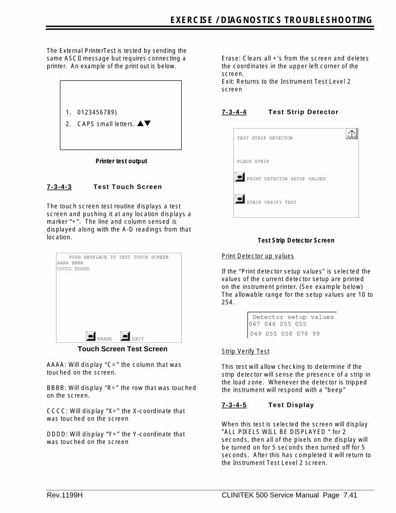
EXERCISE / DIAGNOSTICS TROUBLESHOOTING
Rev.1199H CLINITEK 500 Service Manual Page 7.41
The External PrinterTest is tested by sending thesame ASCII message but requires connecting aprinter. An example of the print out is below.
7-3-4-3 Test Touch Screen
The touch screen test routine displays a testscreen and pushing it at any location displays amarker “+”. The line and column sensed isdisplayed along with the A-D readings from thatlocation.
Touch Screen Test Screen
AAAA: Will display “C=” the column that wastouched on the screen.
BBBB: Will display “R=” the row that was touchedon the screen.
CCCC: Will display “X=” the X-coordinate thatwas touched on the screen
DDDD: Will display “Y=” the Y-coordinate thatwas touched on the screen
Erase: Clears all +’s from the screen and deletesthe coordinates in the upper left corner of thescreen.Exit: Returns to the Instrument Test Level 2screen
7-3-4-4 Test Strip Detector
Print Detector up values
If the “Print detector setup values” is selected thevalues of the current detector setup are printedon the instrument printer. (See example below)The allowable range for the setup values are 10 to254.
Strip Verify Test
This test will allow checking to determine if thestrip detector will sense the presence of a strip inthe load zone. Whenever the detector is trippedthe instrument will respond with a “beep”
7-3-4-5 Test Display
When this test is selected the screen will display”ALL PIXELS WILL BE DISPLAYED “ for 2seconds, then all of the pixels on the display willbe turned on for 5 seconds then turned off for 5seconds. After this has completed it will return tothe Instrument Test Level 2 screen.
PUSH ANYPLACE TO TEST TOUCH SCREENAAAA BBBBCCCCC DDDDD
ERASE EXIT
TEST STRIP DETECTOR
PLACE STRIP
PRINT DETECTOR SETUP VALUES
STRIP VERIFY TEST
Detector setup values067 046 055 055049 055 058 078 99
1. 0123456789)
2. CAPS small letters. st
Printer test output
Test Strip Detector Screen
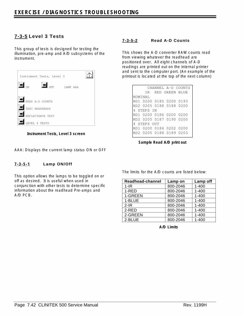
EXERCISE / DIAGNOSTICS TROUBLESHOOTING
Page 7.42 CLINITEK 500 Service Manual Rev. 1199H
7-3-5 Level 3 Tests
This group of tests is designed for testing theillumination, pre-amp and A/D subsystems of theinstrument.
AAA: Displays the current lamp status ON or OFF
7-3-5-1 Lamp ON/Off
This option allows the lamps to be toggled on oroff as desired. It is useful when used inconjunction with other tests to determine specificinformation about the readhead Pre-amps andA/D PCB.
7-3-5-2 Read A-D Counts
This shows the A-D converter RAW counts readfrom viewing whatever the readhead arepositioned over. All eight channels of A-Dreadings are printed out on the internal printerand sent to the computer port. (An example of theprintout is located at the top of the next column)
The limits for the A/D counts are listed below:
Readhead-channel Lamp on Lamp off1-IR 800-2046 1-4001-RED 800-2046 1-4001-GREEN 800-2046 1-4001-BLUE 800-2046 1-4002-IR 800-2046 1-4002-RED 800-2046 1-4002-GREEN 800-2046 1-4002-BLUE 800-2046 1-400
A/D Limits
Instrument Tests, Level 3
ON OFF LAMP AAA
READ A-D COUNTS
TEST READHEADS
REFLECTANCE TEST
LEVEL 4 TESTS
Instrument Tests, Level 3 screen
CHANNEL A-D COUNTS IR RED GREEN BLUENOMINALRD1 0200 0185 0200 0193RD2 0205 0188 0188 02004 STEPS INRD1 0200 0186 0200 0200RD2 0205 0187 0190 02004 STEPS OUTRD1 0200 0186 0202 0200RD2 0205 0188 0189 0203
Sample Read A/D print out
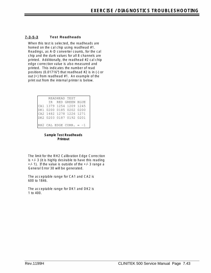
EXERCISE / DIAGNOSTICS TROUBLESHOOTING
Rev.1199H CLINITEK 500 Service Manual Page 7.43
7-3-5-3 Test Readheads
When this test is selected, the readheads arehomed on the cal chip using readhead #1.Readings, as A-D converter counts, for the calchip and the dark values for all 8 channels areprinted. Additionally, the readhead #2 cal chipedge correction value is also measured andprinted. This indicates the number of readpositions (0.01716") that readhead #2 is in (-) orout (+) from readhead #1. An example of theprint out from the internal printer is below.
The limit for the RH2 Calibration Edge Correctionis +/- 3 (it is highly desirable to have this reading+/- 1). If the value is outside of the +/- 3 range aGeneral Error 30 will be generated.
The acceptable range for CA1 and CA2 is600 to 1846.
The acceptable range for DK1 and DK2 is1 to 400.
READHEAD TESTIR RED GREEN BLUE
CA1 1379 1254 1209 1245DK1 0200 0185 0202 0200CA2 1482 1278 1226 1271DK2 0203 0187 0192 0201
RH2 CAL EDGE CORR. = -1
Sample Test ReadheadsPrintout

EXERCISE / DIAGNOSTICS TROUBLESHOOTING
Page 7.44 CLINITEK 500 Service Manual Rev. 1199H
7-3-5-4 Reflectance Test
(Displays the "Place Test Strip" screen)
A hard standards strip is placed at the loadstation of the fixed table and "OK" pushed to startthe operation. The strip is moved to the firstreadhead, scanned and then moved to thesecond readhead, scanned and moved to thewaste station. The reflectance values for all 11pad positions from each readhead (a total of 88reflectance values) are then available for printoutor output to the PC port. At the completion of thetest the user may print the test data from either orboth readheads (See example of the printout).The user also has the option of repeating the test.
Reflectance Test Start Screen
Reflectance Test Completed Screen
REFLECTANCE TEST Both read-heads, 11 positions (A11/B11 at tip)
OK (Place TEST Strip)
REFLECTANCE TEST Both read-heads, 11 positions (A11/B11 at tip)
OK (Place TEST Strip)
PRINT READHEAD #1 DATA
PRINT READHEAD #2 DATA
#00001 9707161505 3000 80 IR RED GREEN BLUEA1 0113 0057 0089 0107A2 0113 0064 0097 0144A3 0038 0028 0097 0097A4 0125 0068 0106 0107A5 0115 0057 0101 0107A6 0113 0057 0093 0090A7 0113 0057 0089 0097A8 0115 0057 0097 0114A9 0110 0057 0093 0124A10 0066 0036 0114 0084A11 0113 0057 0080 0090
Sample Readhead 1 Data
#00001 9707161505 3000 80 IR RED GREEN BLUEB1 0113 0057 0089 0107B2 0113 0064 0097 0144B3 0038 0028 0097 0097B4 0125 0068 0106 0107B5 0115 0057 0101 0107B6 0113 0057 0093 0090B7 0113 0057 0089 0097B8 0115 0057 0097 0114B9 0110 0057 0093 0124B10 0066 0036 0114 0084B11 0113 0057 0080 0090
Sample Readhead 2 Data
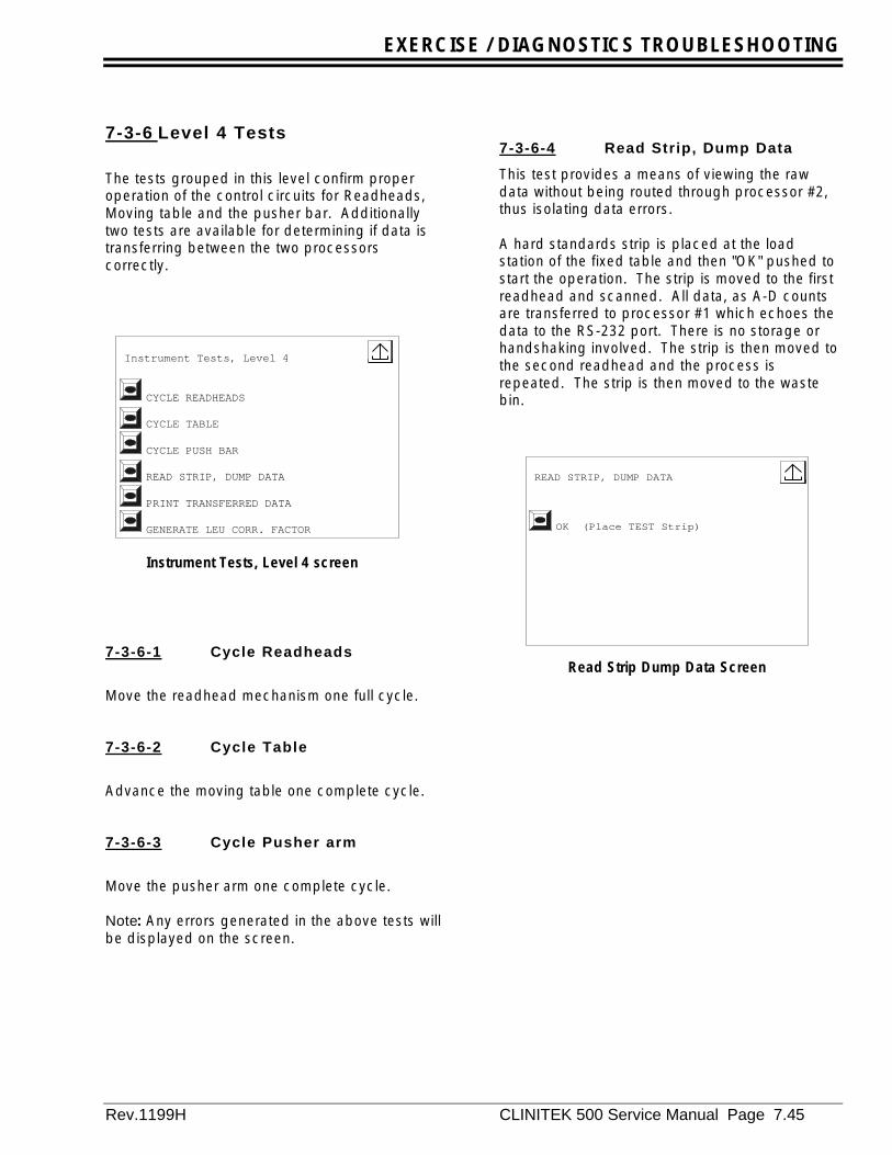
EXERCISE / DIAGNOSTICS TROUBLESHOOTING
Rev.1199H CLINITEK 500 Service Manual Page 7.45
7-3-6 Level 4 Tests
The tests grouped in this level confirm properoperation of the control circuits for Readheads,Moving table and the pusher bar. Additionallytwo tests are available for determining if data istransferring between the two processorscorrectly.
7-3-6-1 Cycle Readheads
Move the readhead mechanism one full cycle.
7-3-6-2 Cycle Table
Advance the moving table one complete cycle.
7-3-6-3 Cycle Pusher arm
Move the pusher arm one complete cycle.
Note: Any errors generated in the above tests willbe displayed on the screen.
7-3-6-4 Read Strip, Dump Data
This test provides a means of viewing the rawdata without being routed through processor #2,thus isolating data errors.
A hard standards strip is placed at the loadstation of the fixed table and then "OK" pushed tostart the operation. The strip is moved to the firstreadhead and scanned. All data, as A-D countsare transferred to processor #1 which echoes thedata to the RS-232 port. There is no storage orhandshaking involved. The strip is then moved tothe second readhead and the process isrepeated. The strip is then moved to the wastebin.
READ STRIP, DUMP DATA
OK (Place TEST Strip)
Read Strip Dump Data Screen
Instrument Tests, Level 4
CYCLE READHEADS
CYCLE TABLE
CYCLE PUSH BAR
READ STRIP, DUMP DATA
PRINT TRANSFERRED DATA
GENERATE LEU CORR. FACTOR
Instrument Tests, Level 4 screen

EXERCISE / DIAGNOSTICS TROUBLESHOOTING
Page 7.46 CLINITEK 500 Service Manual Rev. 1199H
7-3-6-5 Print Transferred Data
Allows printing of whatever data message waslast sent to processor #1 from processor #2 onthe instrument printer see example below.
7-3-6-6 Leukocyte CorrectionFactor Generation
Equipment Required
• Instrument Test Card (version 1.03 / 1.03 orhigher)
• CT500 Calibration Solution (95002503)• Multistix 10 SG reagent strips (10 each)• Urinetek tubes of equivalent• Test Tube Holder (optional)• Paper Towel
To reduce variability between instruments, a"Correction Factor" was added to the Leukocytealgorithm. This factor accounts for minorvariations of Reagent Strip alignment andReadhead position during data collection thatexists between systems. This Correction Factorcan only be set using the Instrument Test Card.New instruments will have this factor set duringmanufacturing; existing instruments (with1.04/1.03 user software or above) should have
this Factor set during normal service releasetesting. Existing instruments in the field will notnecessarily need this procedure performed butmay if required to satisfy customer expectationsfor LEU performance
This test takes reading from a Multistix 10 SGreagent strip which has been dipped into“CLINITEK 500 Calibration Solution” (part number95002503). Ten strips are required to be processedby the instrument during this test. The instrumentprocess the data collected and results are printed,displayed on the screen and stored in theinstrument SRAM for permanent use by theinstrument.
Scroll through the menu options until you reachthe “Instrument Tests, Level 4” menu (see below).Select the “Generate LEU Corr Factor" menuoption.
The first screen displayed in the LEU CorrectionFactor test is shown below.
00#00003 9707151307 0000446608 2508 0707 5608 22050856 0503 0612 0489 05710665 0688 0707 0609 10630636 0658 0623 0519 09800804 0825 0753 0609 19630826 0830 0722 0573 11440844 0761 0660 0534 08420838 0761 0660 0534 08420838 0755 0614 0431 07330868 0820 0683 0608 08340426 0388 0370 0350 02920842 0814 0691 0590 10000830 0819 0722 0648 08719D
Transferred Data Printout
Instrument Tests, Level 4
CYCLE READHEADS
CYCLE TABLE
CYCLE PUSH BAR
READ STRIP, DUMP DATA
PRINT TRANSFERRED DATA
GENERATE LEU CORR. FACTOR
LEU CORRECTION FACTOR: AA
GENERATE LEU CORR. FACTOR
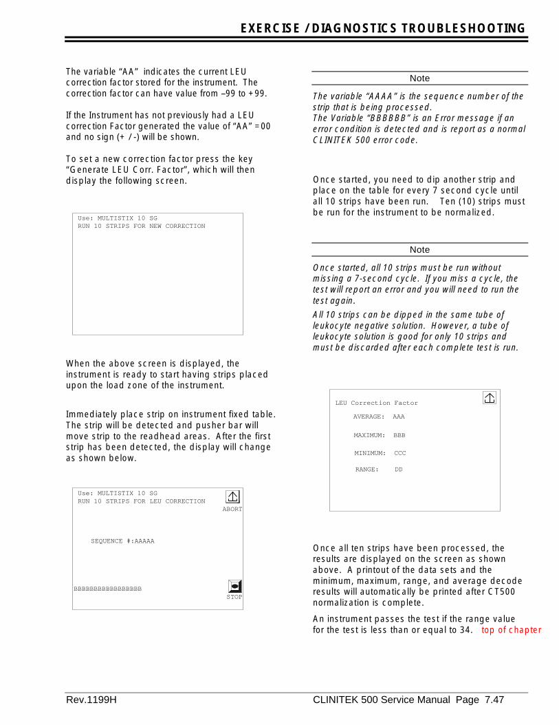
EXERCISE / DIAGNOSTICS TROUBLESHOOTING
Rev.1199H CLINITEK 500 Service Manual Page 7.47
The variable “AA” indicates the current LEUcorrection factor stored for the instrument. Thecorrection factor can have value from –99 to +99.
If the Instrument has not previously had a LEUcorrection Factor generated the value of “AA” =00and no sign (+ / -) will be shown.
To set a new correction factor press the key“Generate LEU Corr. Factor”, which will thendisplay the following screen.
When the above screen is displayed, theinstrument is ready to start having strips placedupon the load zone of the instrument.
Immediately place strip on instrument fixed table.The strip will be detected and pusher bar willmove strip to the readhead areas. After the firststrip has been detected, the display will changeas shown below.
Note
The variable “AAAA” is the sequence number of thestrip that is being processed.The Variable “BBBBBB” is an Error message if anerror condition is detected and is report as a normalCLINITEK 500 error code.
Once started, you need to dip another strip andplace on the table for every 7 second cycle untilall 10 strips have been run. Ten (10) strips mustbe run for the instrument to be normalized.
Note
Once started, all 10 strips must be run withoutmissing a 7-second cycle. If you miss a cycle, thetest will report an error and you will need to run thetest again.All 10 strips can be dipped in the same tube ofleukocyte negative solution. However, a tube ofleukocyte solution is good for only 10 strips andmust be discarded after each complete test is run.
Once all ten strips have been processed, theresults are displayed on the screen as shownabove. A printout of the data sets and theminimum, maximum, range, and average decoderesults will automatically be printed after CT500normalization is complete.
An instrument passes the test if the range valuefor the test is less than or equal to 34. top of chapter
Use: MULTISTIX 10 SG RUN 10 STRIPS FOR NEW CORRECTION
Use: MULTISTIX 10 SG RUN 10 STRIPS FOR LEU CORRECTION
ABORT
SEQUENCE #:AAAAA
BBBBBBBBBBBBBBBBBSTOP
LEU Correction Factor
AVERAGE: AAA
MAXIMUM: BBB
MINIMUM: CCC
RANGE: DD
EXERCISE / DIAGNOSTICS TROUBLESHOOTING
Page 7.48 CLINITEK 500 Service Manual Rev. 1199H
...

EXERCISE DIAGNOSTICS / TROUBLESHOOTING
Rev.1199H CLINITEK 500 Service Manual Page 7.49
7-4 Detailed Troubleshooting andTesting
7-4-0 Introduction
The following section describes how totroubleshoot key subassemblies of the CLINITEK500 instrument to determine if they are operatingproperly.
Caution
Except where otherwise specificallyrequested, always power off and unplug theinstrument when servicing.
When ever working on the instrument withthe cover off the standard Electro StaticDischarge (ESD) precautions should befollowed.
When ever handling the Preamp PCBs, A/DPCB or Lamps clean white cotton glovesmust be worn.
7-4-1 Pre-amp PCB
Equipment required:
Instrument Test Card SR00081CDigital volt meterDisplay service test fixture 71647014
Procedure
1. Remove the upper case (Refer to section 9-8).
2. Reconnect the display, using the Display TestFixture.
3. Install the Instrument Test Card andreconnect the power cord to allow operationduring servicing.
4. Manually position the readhead over thecalibration chip.
5. Using the lamp ON / OFF test in theInstrument Test Card (Refer to section 7-3-5-1) turn the lamp ON.
6. Use a DVM to measure the outputs of the fourchannels of the pre-amp. A convenientlocation to measure these are at connector P1and P2 on the A/D PCB (Refer to figure 7-4-1).Place the ground lead on the power supplychassis and measure the output of pins2,3,4,and 5. Typical readings are 1 to 4 voltswith the lamp on and about 0 with the lamp offrefer to table 7-1 below.
Table 7-1
GRN IR RED BLU LampStatus
Pin 2 3 4 5Vdc 1-4 1-4 1-4 1-4 ONmVdc 0 0 0 0 OFF
Cable to leftPreamp
Cable to rightPreamp
Figure 7-4-1

EXERCISE / DIAGNOSTICS TROUBLESHOOTING
Page 7.50 CLINITEK 500 Service Manual Rev. 1199H
7-4-2 A/D PCB
The A/D PCB provides all of the referencevoltages to the pre-amp PCB. Use the followingprocedure to verify that the correct voltages arebeing provided to the Pre-amp PCBs and lamps.If any of the voltages are not present, the A/DPCB should be replaced.
Equipment required:
Instrument Test Card SR000810Digital volt meterDisplay service test fixture 71647014
Procedure
1. Remove the upper case (Refer to section 9-8).
2. Reconnect the display using the Display TestFixture.
3. Install the Instrument Test Card andreconnect the power cord to allow operationduring servicing.
4. Manually position the readhead over thecalibration chip.
5. Using the lamp ON / OFF test in theInstrument Test Card (Refer to section 7-3-5-1) turn the lamp ON.
6. Measure the lamp voltage between pins 1 and2 on both connector P4 and P5 (Refer tofigure 7-4-1). The unloaded voltage shouldbe between +5.8 VDC and +6.24 VDC.
7. Reconnect the lamps and measure the loadedvoltage. It should be between +5.8 VDC and+6.24 VDC.
8. Measure the voltages at pin 7 of connectorsP1 and P2 (Refer to figure 7-4-1), voltagesshould be 4.95 VDC to 5.05 VDC.
9. Measure the voltages at pin 8 of connectorsP1 and P2 (Refer to figure 7-4-1), voltagesshould be-5.2 VDC to –4.84 VDC.
10. The input voltage measured on P3: pin 4should be -12 VDC and pins 9 & 10 shouldbe+12 VDC.
7-4-3 Mother PCB
7-4-3-1 Power input
Equipment required:
• Instrument Test Card SR00081C• Digital volt meter or equivalent• Display service test fixture 71647014
Procedure
1. Remove the upper case (Refer to section 9-8).
2. Reconnect the display, using the Display TestFixture.
3. Install the Instrument Test Card andreconnect the power cord to allow operationduring servicing 1
4. Measure the output voltage from the powersupply at connector P12 on the mother PCB(Refer to figures 8-1). Place the NEG lead ofa DVM on pin 3 or 4 (GND) and the POS. leadon the following pins. The voltage should bewithin 10% of the listed voltages below.
Pin 1 &2 +5 VDC
Pin 6 -12 VDC
Pin 9 +12 VDC

EXERCISE DIAGNOSTICS / TROUBLESHOOTING
Rev.1199H CLINITEK 500 Service Manual Page 7.51
7-4-3-2 Power to the Strip Detector
Equipment required:
• Instrument Test Card SR00081C• Digital volt meter or equivalent• Display service test fixture 71647014
Procedure
1. Remove the upper case (Refer to section 9-8).
2. Reconnect the display using the Display TestFixture.
3. Install the Instrument Test Card andreconnect the power cord to allow operationduring servicing 1
4. Power to the Strip Detector can be checkedon the back of the strip detector PCB ( Referto figure 7-4-2). Place the NEG lead of theDVM on Pin 1,4,or 5 which are GND (Themeter can also be connected to the powersupply chassis for the DC ground).
5. Connect the POS. lead of the DVM to Pin 3 ofthe cable, the voltage should be +12 VDC.Connecting the POS. lead of the DVM to Pin 2of connector 8 the voltage should be -12VDC.
7-4-3-3 Power to the Printer
Equipment required:
• Instrument Test Card SR00081C• Digital volt meter or equivalent• Display service test fixture 71647014
Procedure
1. Disconnect the line cord from the power entrymodule and remove the upper case(Refer to section 9-8).
2. Reconnect the line cord to the power entrymodule and turn the power switch ON.
3. Connector P7 on the Mother PCB provides thepower to the printer. Remove the cable fromthe connector.
4. Measure the voltages present at theconnector: connect the NEG lead of the DVMto Pin3 (GND) and the POS. lead to Pin 1.The voltage should be +5.0 VDC. Move thePOS. lead to Pin 2 the voltage should also be+5.0 VDC. If the voltages are not presentcheck to see if the power supply is operating(Refer to section7-4-3-1).
Pin 1
Figure 7-4-2
EXERCISE / DIAGNOSTICS TROUBLESHOOTING
Page 7.52 CLINITEK 500 Service Manual Rev. 1199H
7-4-3-4 Stepper Motor DriveCircuits
The following procedure will determine if thestepper motor drive circuits are functioningcorrectly.
Equipment required:
• Oscilloscope• Instrument Test Card SR00081C• Display service test fixture 71647014
Procedure
1. Remove the upper case (Refer to section 9-8).
2. Reconnect the display, using the Display TestFixture.
3. Install the Instrument Test Card andreconnect the power cord to allow operationduring servicing 1
4. Use the Instrument Test Card to excise allmotor functions of the instrument (section 7-3-3-2). Measure the output of IC 5, 6 or 7 atpins 8, 1, 6, and 3 while the appropriatestepper motor is operating. The waveformsobserved should be a square wave.
Note
The waveform will exhibit some inductivenoise as the winding is turned off.
5. To determine if the stepper motor driver chipif functioning properly, Measure the inputsignal at Pin 11 (see table7-4-2 for durationtimes).
If the input is present but any of the output waveforms are missing or not of the proper shape(should be square-wave), replace the Mother PCB
If there is no input signal then the problem lies onthe Processor PCB.
7-4-3-5 Trouble shooting the RS232ports
Equipment required
• Instrument Test Card SR00081C• RJ45 RS232 Loop Back connector 71647006• DB-25 RS232 Loop Back connector 71520102
Procedure
1. Install the Instrument Test Card and use thetest software (Refer to section 7 3-4-1) tocheck to see if the ports work with the loopback connector.
2. Repeat the loop back test for each port. If thetest fails replace the motherboard and rerunthe test.
If the test fails for a second time the problem lieson the Processor PCB and it will requirereplacement
7-4-3-6 Bar code reader communications
Equipment required
• Instrument Test Card SR00081C• DB-25 RS232 Loop Back connector 71520102• Digital Volt meter• Bar code port Loop-Back test fixture
71647007
Procedure
1. Install the Instrument Test Card and select theserial port tests (Refer to section 7-3-4-1)
2. Using the Bar-code port test fixture, measurethe voltage at connector J5. The voltagebetween pin 6 and ground, pin 1 or 3, shouldbe 5 VDC. The voltage between pin 7 andpins 1 or 3 should be +12 VDC.
3. If these voltages are not present the AutoReset Fuses are damaged. Replace theMother PCB
4. Use the Bar code test port fixture and enterthe bar code reader communications test.(Refer to section 7-3-4-1) If the test passesthe problem is with the bar code reader, if itfails replace the motherboard and retest.
5. If the test fails a second time, replace theMain Processor PCB.
Table 7-4-2
ICNumber Pin Number
PulseLength
U5 11 3 msecU6 11 3 msecU7 ( travel out) 11 2 msecU7 (travel in) 11 1 msec
EXERCISE DIAGNOSTICS / TROUBLESHOOTING
Rev.1199H CLINITEK 500 Service Manual Page 7.53
7-4-4 Sensor Tests
Equipment required:
• Instrument Test Card SR00081C• Digital volt meter or equivalent• Display service test fixture 71647014
Procedure
1. Remove the upper case (Refer to section 9-8).
2. Reconnect the display using the Display TestFixture.
3. Install the Instrument Test Card andreconnect the power cord to allow operationduring servicing.
4. Turn the instrument on. Select the first levelof instrument tests and select Sensor Status(Refer to section 7-3-3-3).
5. Interrupt each of the sensors and observe thatthe status changes. If the status fails tochange replace the sensor and perform thetest a second time.
6. If the sensor test fails a second time, theproblem may lie in the Mother PCB or with theMain PCB.
7-4-5 Display TestingEquipment required:
• Instrument Test Card SR00081C• Digital volt meter or equivalent• Display service test fixture 71647014
Procedure
1. Remove the upper case (Refer to section 9-8).
2. Reconnect the display, using the Display TestFixture.
3. Install the Instrument Test Card andreconnect the power cord to allow operationduring servicing. Next select display testdisplay (Refer to section 7-3-3-5). If thedisplay fails this test, proceed to the nextstep.
4. Verify that the display assembly is receivingpower. Remove the Display bezel assemblyfrom the instrument leaving the cableconnected to the Main Processor PCB.
5. Using a volt meter check for voltage beingpresent on the display interface PCB while theinstrument power is on. top of chapter
6. Connect the Negative lead of the volt meter toconnector P2 pin 20 and connect the positivelead to pins 5, 16 and 17. The voltagemeasured on each of these pins should be+5 VDC.
7. Connect the positive lead to Pin 1,its voltageshould be +12 VDC.
8. If the voltages are not present on the display,check the connector on the Main ProcessorPCB for the voltages.
9. If the voltage is presenton the main processorPCB then the display assembly is defectiveand requires replacement.
7-4-6 Main Processor PCB
Equipment required:
• Instrument Test Card SR00081C• Digital volt meter or equivalent• Display service test fixture 71647013• Known good display assembly
Procedure
In the process of testing most of the instrumentfunctions, a determination can be made if theMain Processor PCB board is operating properly.
Since user interface functions are controlled byprocessor 1 and motor control by the processor 2,it is possible to isolate problems to either theSingle inline Memory Module (SIMM) whichcontains processor 1 and its associated supportcircuitry, or the Main PCB which processor 2 islocated on.
1. If on power up (with the program cardremoved), there is no motor movement from;Readhead, moving table or blotter the SIMMmodule is possibly defective and requiresreplacement. (Refer to section 9-12-1)
2. If when the unit is turn on the display is blank,the power supply should be checked forproper output voltage (Refer to section 7-4-3-1). Additionally the cables going to thedisplay should be checked to see if they areseated properly, then the voltage to thedisplay checked (Refer to section 7-4-5).
3. If all the voltages are correct, use a knowngood display to verify that the problem is notthe display. If a known good display fails tooperate then the Main Processor PCB shouldbe replaced (Refer to section 9-12).

EXERCISE / DIAGNOSTICS TROUBLESHOOTING
Page 7.54 CLINITEK 500 Service Manual Rev. 1199H

ALIGNMENTS/ADJUSTMENTS
Rev. 1199H CLINITEK 500 Service Manual Page 8.1
8-0 IntroductionThis section of the manual provides detailedinformation required for making necessaryalignments and adjustments during the ordinarycourse of repair on the CLINITEK® 500 UrineChemistry Analyzer. It also describes whatspecial fixtures are required and how to use them.
Caution
Except where otherwise specificallyrequested, always power off and unplugthe instrument when servicing.
Whenever working on the instrumentwith the cover off the standardElectrostatic Discharge (ESD)precautions should be followed.
Whenever handling the Preamp PCBs,A/D PCB or Lamps clean white cottongloves must be worn.
CHAPTER EIGHT-ALIGNMENTS / ADJUSTMENTS Return
SectionIntroduction ------------------------------------------------------------------------------------------------------ 8-0Voltage adjustments------------------------------------------------------------------------------------------- 8-1Readhead alignment ------------------------------------------------------------------------------------------ 8-2Horizontal plate adjustment --------------------------------------------------------------------------------- 8-3Printer adjustments / cleaning ------------------------------------------------------------------------------ 8-4
Cleaning print mechanism --------------------------------------------------------------------------- 8-4-1Cleaning the printer platen--------------------------------------------------------------------------- 8-4-2
Sensor adjustments ------------------------------------------------------------------------------------------- 8-5Blotter slide lubrication---------------------------------------------------------------------------------------- 8-6
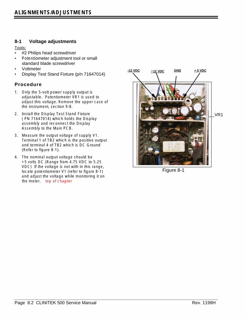
ALIGNMENTS/ADJUSTMENTS
Page 8.2 CLINITEK 500 Service Manual Rev. 1199H
8-1 Voltage adjustmentsTools:• #2 Philips head screwdriver• Potentiometer adjustment tool or small
standard blade screwdriver• Voltmeter• Display Test Stand Fixture (p/n 71647014)
Procedure
1. Only the 5-volt power supply output isadjustable. Potentiometer VR1 is used toadjust this voltage. Remove the upper case ofthe instrument, section 9-8.
2. Install the Display Test Stand Fixture( PN 71647014) which holds the Displayassembly and reconnect the DisplayAssembly to the Main PCB.
3. Measure the output voltage of supply V1.Terminal 1 of TB2 which is the positive outputand terminal 4 of TB2 which is DC Ground(Refer to figure 8-1).
4. The nominal output voltage should be+5 volts DC (Range from 4.75 VDC to 5.25VDC) If the voltage is not with in this range,locate potentiometer V1 (refer to figure 8-1)and adjust the voltage while monitoring it onthe meter. top of chapter
-12 VDC +12 VDC GND + 5 VDC
VR1
Figure 8-1
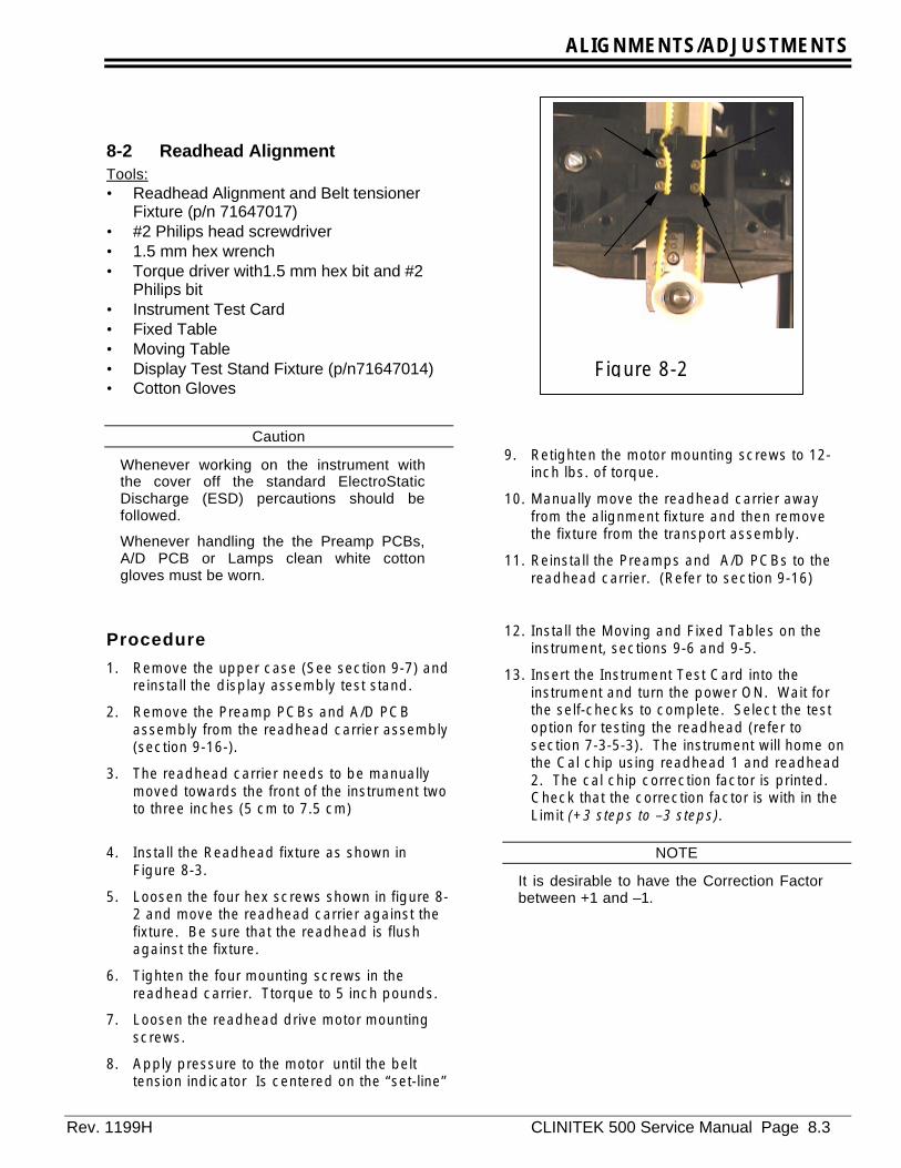
ALIGNMENTS/ADJUSTMENTS
Rev. 1199H CLINITEK 500 Service Manual Page 8.3
8-2 Readhead AlignmentTools:• Readhead Alignment and Belt tensioner
Fixture (p/n 71647017)• #2 Philips head screwdriver• 1.5 mm hex wrench• Torque driver with1.5 mm hex bit and #2
Philips bit• Instrument Test Card• Fixed Table• Moving Table• Display Test Stand Fixture (p/n71647014)• Cotton Gloves
Caution
Whenever working on the instrument withthe cover off the standard ElectroStaticDischarge (ESD) percautions should befollowed.
Whenever handling the the Preamp PCBs,A/D PCB or Lamps clean white cottongloves must be worn.
Procedure
1. Remove the upper case (See section 9-7) andreinstall the display assembly test stand.
2. Remove the Preamp PCBs and A/D PCBassembly from the readhead carrier assembly(section 9-16-).
3. The readhead carrier needs to be manuallymoved towards the front of the instrument twoto three inches (5 cm to 7.5 cm)
4. Install the Readhead fixture as shown inFigure 8-3.
5. Loosen the four hex screws shown in figure 8-2 and move the readhead carrier against thefixture. Be sure that the readhead is flushagainst the fixture.
6. Tighten the four mounting screws in thereadhead carrier. Ttorque to 5 inch pounds.
7. Loosen the readhead drive motor mountingscrews.
8. Apply pressure to the motor until the belttension indicator Is centered on the “set-line”
9. Retighten the motor mounting screws to 12-inch lbs. of torque.
10. Manually move the readhead carrier awayfrom the alignment fixture and then removethe fixture from the transport assembly.
11. Reinstall the Preamps and A/D PCBs to thereadhead carrier. (Refer to section 9-16)
12. Install the Moving and Fixed Tables on theinstrument, sections 9-6 and 9-5.
13. Insert the Instrument Test Card into theinstrument and turn the power ON. Wait forthe self-checks to complete. Select the testoption for testing the readhead (refer tosection 7-3-5-3). The instrument will home onthe Cal chip using readhead 1 and readhead2. The cal chip correction factor is printed.Check that the correction factor is with in theLimit (+3 steps to –3 steps).
NOTE
It is desirable to have the Correction Factorbetween +1 and –1.
Figure 8-2
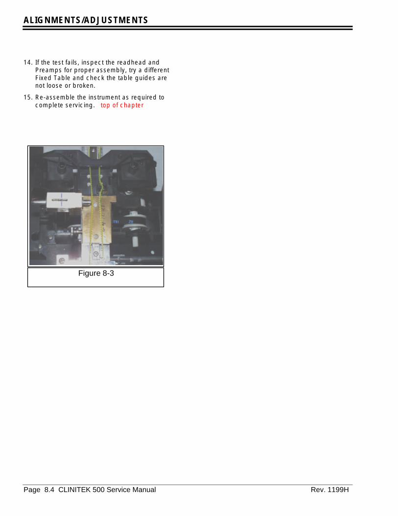
ALIGNMENTS/ADJUSTMENTS
Page 8.4 CLINITEK 500 Service Manual Rev. 1199H
14. If the test fails, inspect the readhead andPreamps for proper assembly, try a differentFixed Table and check the table guides arenot loose or broken.
15. Re-assemble the instrument as required tocomplete servicing. top of chapter
Figure 8-3
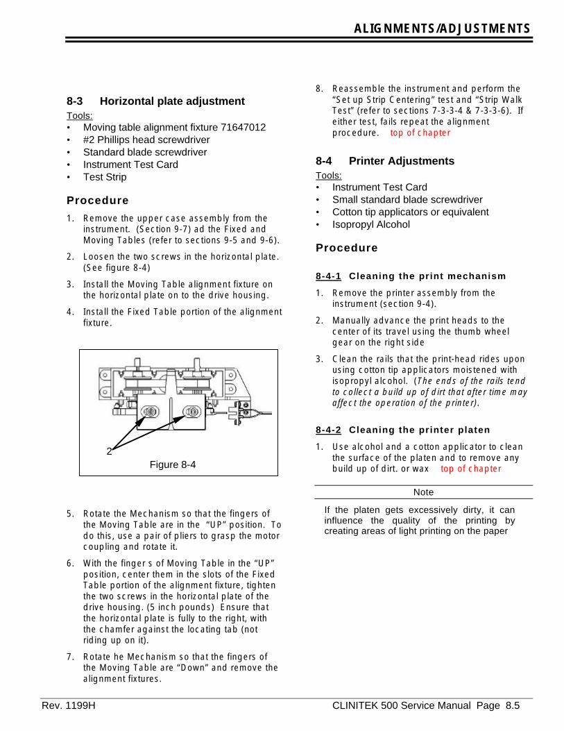
ALIGNMENTS/ADJUSTMENTS
Rev. 1199H CLINITEK 500 Service Manual Page 8.5
8-3 Horizontal plate adjustmentTools:• Moving table alignment fixture 71647012• #2 Phillips head screwdriver• Standard blade screwdriver• Instrument Test Card• Test Strip
Procedure
1. Remove the upper case assembly from theinstrument. (Section 9-7) ad the Fixed andMoving Tables (refer to sections 9-5 and 9-6).
2. Loosen the two screws in the horizontal plate.(See figure 8-4)
3. Install the Moving Table alignment fixture onthe horizontal plate on to the drive housing.
4. Install the Fixed Table portion of the alignmentfixture.
5. Rotate the Mechanism so that the fingers ofthe Moving Table are in the “UP” position. Todo this, use a pair of pliers to grasp the motorcoupling and rotate it.
6. With the finger s of Moving Table in the “UP”position, center them in the slots of the FixedTable portion of the alignment fixture, tightenthe two screws in the horizontal plate of thedrive housing. (5 inch pounds) Ensure thatthe horizontal plate is fully to the right, withthe chamfer against the locating tab (notriding up on it).
7. Rotate he Mechanism so that the fingers ofthe Moving Table are “Down” and remove thealignment fixtures.
8. Reassemble the instrument and perform the“Set up Strip Centering” test and “Strip WalkTest” (refer to sections 7-3-3-4 & 7-3-3-6). Ifeither test, fails repeat the alignmentprocedure. top of chapter
8-4 Printer AdjustmentsTools:• Instrument Test Card• Small standard blade screwdriver• Cotton tip applicators or equivalent• Isopropyl Alcohol
Procedure
8-4-1 Cleaning the print mechanism
1. Remove the printer assembly from theinstrument (section 9-4).
2. Manually advance the print heads to thecenter of its travel using the thumb wheelgear on the right side
3. Clean the rails that the print-head rides uponusing cotton tip applicators moistened withisopropyl alcohol. (The ends of the rails tendto collect a build up of dirt that after time mayaffect the operation of the printer).
8-4-2 Cleaning the printer platen
1. Use alcohol and a cotton applicator to cleanthe surface of the platen and to remove anybuild up of dirt. or wax top of chapter
Note
If the platen gets excessively dirty, it caninfluence the quality of the printing bycreating areas of light printing on the paper
2Figure 8-4
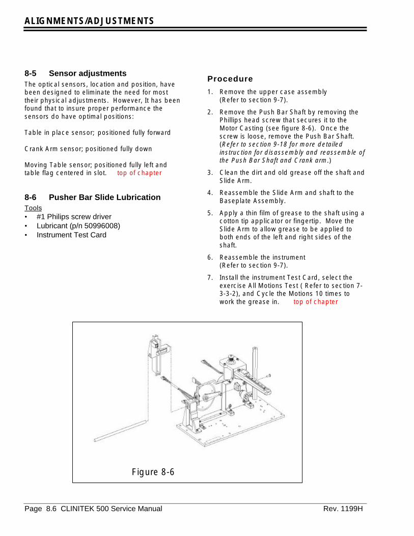
ALIGNMENTS/ADJUSTMENTS
Page 8.6 CLINITEK 500 Service Manual Rev. 1199H
8-5 Sensor adjustmentsThe optical sensors, location and position, havebeen designed to eliminate the need for mosttheir physical adjustments. However, It has beenfound that to insure proper performance thesensors do have optimal positions:
Table in place sensor; positioned fully forward
Crank Arm sensor; positioned fully down
Moving Table sensor; positioned fully left andtable flag centered in slot. top of chapter
8-6 Pusher Bar Slide LubricationTools• #1 Philips screw driver• Lubricant (p/n 50996008)• Instrument Test Card
Procedure
1. Remove the upper case assembly(Refer to section 9-7).
2. Remove the Push Bar Shaft by removing thePhillips head screw that secures it to theMotor Casting (see figure 8-6). Once thescrew is loose, remove the Push Bar Shaft.(Refer to section 9-18 for more detailedinstruction for disassembly and reassemble ofthe Push Bar Shaft and Crank arm.)
3. Clean the dirt and old grease off the shaft andSlide Arm.
4. Reassemble the Slide Arm and shaft to theBaseplate Assembly.
5. Apply a thin film of grease to the shaft using acotton tip applicator or fingertip. Move theSlide Arm to allow grease to be applied toboth ends of the left and right sides of theshaft.
6. Reassemble the instrument(Refer to section 9-7).
7. Install the instrument Test Card, select theexercise All Motions Test ( Refer to section 7-3-3-2), and Cycle the Motions 10 times towork the grease in. top of chapter
Figure 8-6

REPAIR / REPLACEMENT
Rev. 1199H CLINITEK 500 Service Manual Page 9.1
9-0 IntroductionThis section contains instructions for servicing theCLINITEK® 500 Urine Chemistry Analyzer.Special reassemble precautions are noted.
Always perform the preventive maintenanceprocedures in Section Five when servicing thisinstrument. The “Service Release Protocol” fromchapter 12 must be performed prior to theinstrument return to the customer for use.
Caution
Except where otherwise specificallyrequested always power off and unplugthe instrument when servicing.
Whenever working on the instrumentwith the cover off the standard ElectroStatic Discharge (ESD) precautionsshould be followed.
Whenever handling the Pre-amp PCBs,A/D PCB or Lamps clean white cottongloves must be worn.
SectionIntroduction-------------------------------------------------------------------------------------------------------9-0Push Bar ----------------------------------------------------------------------------------------------------------9-1PCMCIA-----------------------------------------------------------------------------------------------------------9-2Printer Module---------------------------------------------------------------------------------------------------9-3Bezel---------------------------------------------------------------------------------------------------------------9-4Fixed Table-------------------------------------------------------------------------------------------------------9-5Moving Table ----------------------------------------------------------------------------------------------------9-6Upper Case ------------------------------------------------------------------------------------------------------9-7Fan -----------------------------------------------------------------------------------------------------------------9-7-1Table Guide
Left -------------------------------------------------------------------------------------------------9-8Right -----------------------------------------------------------------------------------------------9-9
Power Supply----------------------------------------------------------------------------------------------------9-10Processor PCB--------------------------------------------------------------------------------------------------9-11
SIMM PCB ---------------------------------------------------------------------------------------9-11-1Electronics Bracket---------------------------------------------------------------------------------------------9-12The Mother PCB ------------------------------------------------------------------------------------------------9-13Strip Detector ----------------------------------------------------------------------------------------------------9-14Lamp---------------------------------------------------------------------------------------------------------------9-15Pre-amp & A/D --------------------------------------------------------------------------------------------------9-16 A/D PCB -------------------------------------------------------------------------------------------9-16-1 Pre-amp PCBs -----------------------------------------------------------------------------------9-16-2Drive Housing ---------------------------------------------------------------------------------------------------9-17Crank Arm --------------------------------------------------------------------------------------------------------9-18Baseplate Mechanism-----------------------------------------------------------------------------------------9-19Lower Case Assembly-----------------------------------------------------------------------------------------9-20
Power entry --------------------------------------------------------------------------------------9-20-1Touch Screen ---------------------------------------------------------- -----------------------------------------9-21Printer Interface PCB ------------------------------------------------------------------------------------------9-22
CHAPTER NINE – REPAIR / REPLACEMENT Return
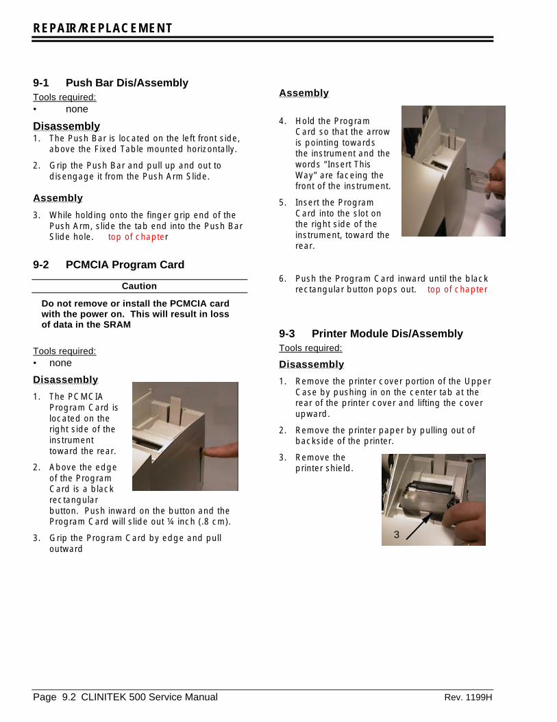
REPAIR/REPLACEMENT
Page 9.2 CLINITEK 500 Service Manual Rev. 1199H
9-1 Push Bar Dis/AssemblyTools required:• none
Disassembly1. The Push Bar is located on the left front side,
above the Fixed Table mounted horizontally.
2. Grip the Push Bar and pull up and out todisengage it from the Push Arm Slide.
Assembly
3. While holding onto the finger grip end of thePush Arm, slide the tab end into the Push BarSlide hole. top of chapter
9-2 PCMCIA Program Card
Caution
Do not remove or install the PCMCIA cardwith the power on. This will result in lossof data in the SRAM
Tools required:• none
Disassembly
1. The PCMCIAProgram Card islocated on theright side of theinstrumenttoward the rear.
2. Above the edgeof the ProgramCard is a blackrectangularbutton. Push inward on the button and theProgram Card will slide out ¼ inch (.8 cm).
3. Grip the Program Card by edge and pulloutward
Assembly
4. Hold the ProgramCard so that the arrowis pointing towardsthe instrument and thewords “Insert ThisWay” are faceing thefront of the instrument.
5. Insert the ProgramCard into the slot onthe right side of theinstrument, toward therear.
6. Push the Program Card inward until the blackrectangular button pops out. top of chapter
9-3 Printer Module Dis/AssemblyTools required:
Disassembly
1. Remove the printer cover portion of the UpperCase by pushing in on the center tab at therear of the printer cover and lifting the coverupward.
2. Remove the printer paper by pulling out ofbackside of the printer.
3. Remove theprinter shield.
3
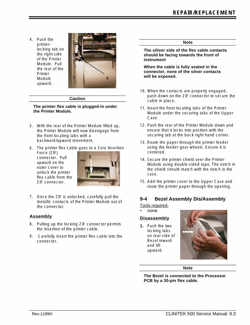
REPAIR/REPLACEMENT
Rev.1199H CLINITEK 500 Service Manual 9.3
4. Push theprinter-locking tab onthe right sideof the PrinterModule. Pullthe rear of thePrinterModuleupward.
Caution
The printer flex cable is plugged-in underthe Printer Module.
5. With the rear of the Printer Module lifted up,the Printer Module will now disengage fromthe front locating tabs with abackward/upward movement.
6. The printer flex cable goes to a Zero InsertionForce (ZIF)connector. Pullupward on theouter cover tounlock the printerflex cable from theZIF connector.
7. Once the ZIF is unlocked, carefully pull themetallic contacts of the Printer Module out ofthe connector.
Assembly
8. Pulling up the locking ZIF connector permitsthe insertion of the printer cable.
9. Carefully insert the printer flex cable into theconnector.
Note
The siliver side of the flex cable contactsshould be facing towards the front ofinstrument
When the cable is fully seated in theconnector, none of the silver contactswill be exposed.
10. When the contacts are properly engaged,push down on the ZIF connector to secure thecable in place.
11. Insert the front locating tabs of the PrinterModule under the securing tabs of the UpperCase.
12. Push the rear of the Printer Module down andensure that it locks into position with thesecuring tab at the back right hand corner.
13. Route the paper through the printer feederusing the feeder gear wheels. Ensure it iscentered.
14. Secure the printer shield over the PrinterModule using double-sided tape. The notch inthe shield should match with the notch in thecase.
15. Add the printer cover to the Upper Case androute the printer paper through the opening.
9-4 Bezel Assembly Dis/AssemblyTools required:• none
Disassembly
1. Push the twolocking tabson rear side ofBezel inwardand liftupward.
Note
The Bezel is connected to the ProcessorPCB by a 30-pin flex cable.
4
6
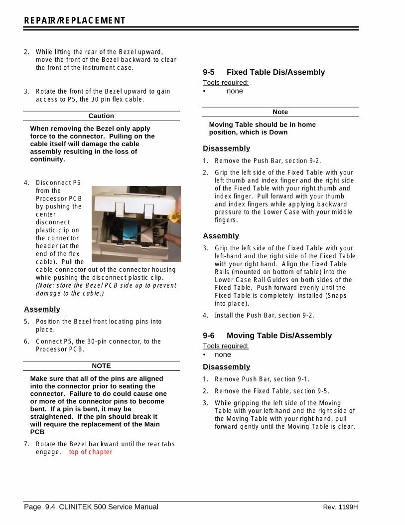
REPAIR/REPLACEMENT
Page 9.4 CLINITEK 500 Service Manual Rev. 1199H
2. While lifting the rear of the Bezel upward,move the front of the Bezel backward to clearthe front of the instrument case.
3. Rotate the front of the Bezel upward to gainaccess to P5, the 30 pin flex cable.
Caution
When removing the Bezel only applyforce to the connector. Pulling on thecable itself will damage the cableassembly resulting in the loss ofcontinuity.
4. Disconnect P5from theProcessor PCBby pushing thecenterdisconnectplastic clip onthe connectorheader (at theend of the flexcable). Pull thecable connector out of the connector housingwhile pushing the disconnect plastic clip.(Note: store the Bezel PCB side up to preventdamage to the cable.)
Assembly
5. Position the Bezel front locating pins intoplace.
6. Connect P5, the 30-pin connector, to theProcessor PCB.
NOTE
Make sure that all of the pins are alignedinto the connector prior to seating theconnector. Failure to do could cause oneor more of the connector pins to becomebent. If a pin is bent, it may bestraightened. If the pin should break itwill require the replacement of the MainPCB
7. Rotate the Bezel backward until the rear tabsengage. top of chapter
9-5 Fixed Table Dis/AssemblyTools required:• none
Note
Moving Table should be in homeposition, which is Down
Disassembly
1. Remove the Push Bar, section 9-2.
2. Grip the left side of the Fixed Table with yourleft thumb and index finger and the right sideof the Fixed Table with your right thumb andindex finger. Pull forward with your thumband index fingers while applying backwardpressure to the Lower Case with your middlefingers.
Assembly
3. Grip the left side of the Fixed Table with yourleft-hand and the right side of the Fixed Tablewith your right hand. Align the Fixed TableRails (mounted on bottom of table) into theLower Case Rail Guides on both sides of theFixed Table. Push forward evenly until theFixed Table is completely installed (Snapsinto place).
4. Install the Push Bar, section 9-2.
9-6 Moving Table Dis/AssemblyTools required:• none
Disassembly
1. Remove Push Bar, section 9-1.
2. Remove the Fixed Table, section 9-5.
3. While gripping the left side of the MovingTable with your left-hand and the right side ofthe Moving Table with your right hand, pullforward gently until the Moving Table is clear.

REPAIR/REPLACEMENT
Rev.1199H CLINITEK 500 Service Manual 9.5
Assembly
4. While gripping the left side of the MovingTable with your left-hand and the right side ofthe Moving Table with your right hand, alignthe Moving Table onto the Drive Housing andgently push onto housing.
5. Reinstall the Fixed Table and Push Bar.
9-7 Upper Case Dis/AssemblyTools required:• #2 Phillips screwdriver for M4 screws, all
others use a #1 Phillips screwdriver
Disassembly
1. Remove the PCMCIA Card, section 9-2.
2. Removethe PrinterModule,section 9-3.
3. Removethe BezelAssembly,section9-4.
4. Removethe Fixed Table, section 9-5.
5. Remove 4 Phillips screwdriver head screwsthat secure the Upper Case to the frame. Twoin the rear of the upper case, one in the frontlower left corner and onre screw in front of theprinter.
6. Unplug the fan connector from the ProcessorPCB.
7. Lift the Upper Case straight up being verycareful of the main PCB.
Assembly
8. Set the Upper Case onto the instrument.
9. Plug the fan connector into J1 on theProcessor PCB.
10. Install the one Phillips screwdriver headscrew that secures the lower front left cornerof the Upper Case to the frame and the one infront of the printer.
11. Install the two Phillips screwdriver headscrews that secure the rear Upper Case to theframe.
12. Install the Moving Table, section 9-6.
13. Install the Fixed Table, section 9-5.
14. Install the Bezel Assembly, section 9-4.
15. Install the Printer Module, section 9-3.
16. Install the PCMCIA Card, section 9-2.
9-7-1 Fan Assembly Dis/AssemblyTools required:• Screwdrivers:#2 Phillips screwdriver for M4
screws, all others use a #1 Phillipsscrewdriver
Disassembly
1. Disassemble the Upper Case,section 9-8.
2. Remove the four hex nuts, located on theinside of the Upper Case, from the fourPhillips screwdriver head screws.
3. Remove the locking washers from the fourPhillips screwdriver head screws.(Note theconfiguration)
4. While holding the Fan Assembly, remove thefour fan screws.
Note
There is a ground strap mounted on theinside left lower screw.
The rear Fan Guard will come off whenthe last screw is removed.
Assembly
5. Install the Fan Assembly with the fan’smanufacturer name and model number facingoutward and horizontal so that it can be readfrom the rear of the instrument.
6. The P1 connector and wire should face upwhile holding the fan to the inside of theUpper Case. Install and hold the Fan Guardat the rear of the instrument.

REPAIR/REPLACEMENT
Page 9.6 CLINITEK 500 Service Manual Rev. 1199H
7. Install one of the four Phillips screwdriverhead screws through the upper left corner ofthe Fan Guard and the Fan Assembly.
8. Install the remaining locking washers and hexnuts.
9. Install the ground strap at the left lower cornerof the fan between the case and the fan.
10. Secure with screw washer and nut.
11. Install the other two screws, washers andnuts.
12. Install the Upper Case, section 9-7. top of chapter

REPAIR/REPLACEMENT
Rev.1199H CLINITEK 500 Service Manual 9.7
9-8 Table Guide-Left Dis/AssemblyTools required:• Screwdrivers:#2 Phillips screwdriver for M4
screws, all others use a #1 Phillipsscrewdriver
Disassembly
1. Remove the PCMCIA Card, section 9-2.
2. Remove the Printer Module section 9-3.
3. Remove the Bezel Assembly,section 9-4.
4. Remove the Fixed Table and Moving Table,sections 9-5 and 9-6.
5. Remove the Upper Case, section 9-7.
6. Remove the three Phillips screwdriver headscrews that secure the Table Guide toMounting Plate (two on left side, one on rightside.)
7. Disconnect theoptical sensorconnector from theMother PCB.
8. Remove the TableGuide.
Assembly
9. Position the Table Guide onto instrumentBaseplate using the locating pins on theguide.
10. Secure the Table Guide to the Mounting Plate,two screws on left side and one on right.
11. Connect the optical sensor connector to P10on the Mother PCB. The sensor wire shouldgo between the Push Bar Rail Support andthe Push Bar Slide. Secure the wires with thetwo plastic clips. Check that there is nointerference with the Push Bar.
12. Install the Upper Case, section 9-7.
13. Install the PCMCIA Card, section 9-2.
14. Install the Moving and Fixed Table, sections9-5 and 9-6.
15. Install the Bezel Assembly, section 9-4.
16. Install the Printer Module, section 9-3.
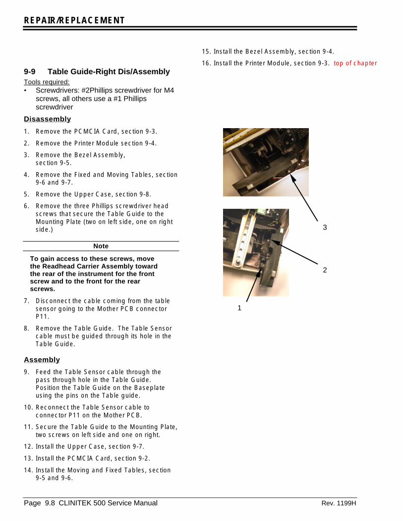
REPAIR/REPLACEMENT
Page 9.8 CLINITEK 500 Service Manual Rev. 1199H
9-9 Table Guide-Right Dis/AssemblyTools required:• Screwdrivers: #2Phillips screwdriver for M4
screws, all others use a #1 Phillipsscrewdriver
Disassembly
1. Remove the PCMCIA Card, section 9-3.
2. Remove the Printer Module section 9-4.
3. Remove the Bezel Assembly,section 9-5.
4. Remove the Fixed and Moving Tables, section9-6 and 9-7.
5. Remove the Upper Case, section 9-8.
6. Remove the three Phillips screwdriver headscrews that secure the Table Guide to theMounting Plate (two on left side, one on rightside.)
Note
To gain access to these screws, movethe Readhead Carrier Assembly towardthe rear of the instrument for the frontscrew and to the front for the rearscrews.
7. Disconnect the cable coming from the tablesensor going to the Mother PCB connectorP11.
8. Remove the Table Guide. The Table Sensorcable must be guided through its hole in theTable Guide.
Assembly
9. Feed the Table Sensor cable through thepass through hole in the Table Guide.Position the Table Guide on the Baseplateusing the pins on the Table guide.
10. Reconnect the Table Sensor cable toconnector P11 on the Mother PCB.
11. Secure the Table Guide to the Mounting Plate,two screws on left side and one on right.
12. Install the Upper Case, section 9-7.
13. Install the PCMCIA Card, section 9-2.
14. Install the Moving and Fixed Tables, section9-5 and 9-6.
15. Install the Bezel Assembly, section 9-4.
16. Install the Printer Module, section 9-3. top of chapter
1
2
3

REPAIR/REPLACEMENT
Rev.1199H CLINITEK 500 Service Manual 9.9
9-10 Power Supply Dis/AssemblyTools required:• #2 Phillips screwdriver for M4 screws, all
others use a #1 Phillips screwdriver• Torque Driver
•
Disassembly
1. Remove the PCMCIA Card, section 9-2.
2. Remove the Printer Module section 9-3.
3. Remove the Bezel Assembly,section 9-4.
4. Remove the Fixed Table, section 9-5.
5. Remove the Upper Case, section 9-7.
6. Disconnect the Power Supply cable whichgoes to the Mother PCB. (P6 to J6 on the topleft side of the Processor PCB)
7. Remove the Phillips screwdriver head screwthat connects the grounding strap from thepower supply to the left rear corner of theBaseplate assembly.
8. Remove the Phillips screwdriver head screwthat holds the top of the Power Supply to theElectronic Mounting Bracket.
9. Lift the Power Supply upward to gain accessto the connector for TB1. Disconnect thecable from connector TB1 and remove thePower Supply.
Assembly
NOTE
If the power supply is being replacedtransfer the Grounding strap from the oldpower supply to the new power supply
10. Lower the Power Supply into the instrument atthe left rear corner. The open componentside faces left with TB2 at the top.
11. Once the Power Supply is low enough,connect the main power cable to TB1.
7
8
7
9
6

REPAIR/REPLACEMENT
Page 9.10 CLINITEK 500 Service Manual Rev. 1199H
12. Continue tolower thePower Supplyonto the bottommounting taps.
Mounting tabs
The bottom ofthe PowerSupply framerests on twomounting tabslocated at thebottom of theElectronicMountingBracket.
13. Install the Phillips screwdriver head screwthat holds the top of the Power Supply to theElectronic Mounting Bracket. Tighten to atorque of 5 inch-pounds.
14. Install the Phillips screwdriver head screw forthe Power Supply grounding strap to the leftrear corner of the Baseplate assembly.
15. Connect The Power Supply connector J12 tothe connector P12 on The Mother PCB.
16. Connect P6 to J6 on the top left side of theProcessor PCB.
17. Install the Upper Case, section 9-8.
18. Install the PCMCIA Card, section 9-3.
19. Install the Moving and Fixed Tables, sections9-7 and 9-6.
20. Install the Bezel Assembly, section 9-5.
21. Install the Printer Module, section 9-4. top of chapter
9-11 Processor PCB (Main)Dis/AssemblyTools required:• Scredrivers: #2 Phillips screwdriver for M4
screws, all others use a #1Phillipsscrewdriver
• Torque Driver
Disassembly1. Remove the PCMCIA Card, section 9-3.
2. Remove the Printer Module section 9-4.
3. Remove the Bezel Assembly, section 9-4.
4. Remove the Fixed and Moving Tables,sections 9-5 and 9-6.
5. Remove the Upper Case, section 9-7.
6. Disconnect the two cables, J6 and J2, on topof the Processor PCB.
7. Disconnect the cable (part number 40453225)located in center of the Processor PCBlooking as viewed from front.
Connector
The connector plugs onto the ProcessorPCB by going through the Electronicbracket assembly first.
12
J6 J2
7

REPAIR/REPLACEMENT
Rev.1199H CLINITEK 500 Service Manual 9.11
8. Position the instrument so that the back isfacing you.
9. Remove the four screws holding the PCB tothe Electronic Bracket.
10. The Processor PCB plugs into the Mother PCBwith two connectors J1 and J2. Gently liftingthe Processor PCB upward will disconnect itfrom the Mother PCB.
Assembly
11. Position the instrument so that the back isfacing you.
12. Plug the Processor PCB onto the connectors,J1 and J2, by gently pressing on the top edgeof the PCB.
13. Install the four screws (SEMS) holding PCB toelectronic bracket. Tighten to a torque of 5inch-pounds.
NOTE
The screw above the PCMCIA cardrequires a lock washer between thescrew head and the PCB
14. Position the instrument so that the back isfacing you.
15. Connect the Printer Interface Assembly cableto J3 located in center of the Processor PCBlooking from the front.
16. Connect the Strip Detector to J6 on the topleft side of the Processor PCB.
17. Connect the Pre-amp A/D to J2 on the topright side of the Processor PCB.
18. Install the Upper Case, section 9-7.
19. Install the PCMCIA Card, section 9-2.
20. Install the Moving and Fixed Tables, section9.6 and 9-5.
21. Install the Bezel Assembly, section 9-4.
22. Install the Printer Module, section 9-3. top of chapter
9-11-1 SIMM PCBDis/Assembly
CAUTION
The SIMM processor must beprogrammed as follows, failure to do sowill lead to damage of the Strip Detectoron initial instrument power up.
1) Install the new SIMM processor
2) Disconnect the strip detector cablefrom the Main Processor PCB (Cable J6)
3) Install the Display into the Display TestStand and reconnect the display.
4) Reconnect the power cord; install theInstrument Test Card (section 9-2).
5) Turn the instrument “ON”. When itasks to reprogram the instrument,respond “YES.”
6) When reprogramming is complete, turnthe power off, remove the InstrumentTest Card disconnect the power cord andreconnect the Strip Detector Cable J6.
Disassembly
1. Remove the PCMCIA Card, section 9-2.
2. Remove the Printer Module section 9-3.
3. Remove the Bezel Assembly, section 9-4.
4. Remove the Fixed and Moving Tables, section9-5 and 9-6.
5. Remove the Upper Case, section 9-7.
6. Position the instrument so that the back isfacing you.
7. Locate the SIMM PCB at the right side of thePCB.
9 9
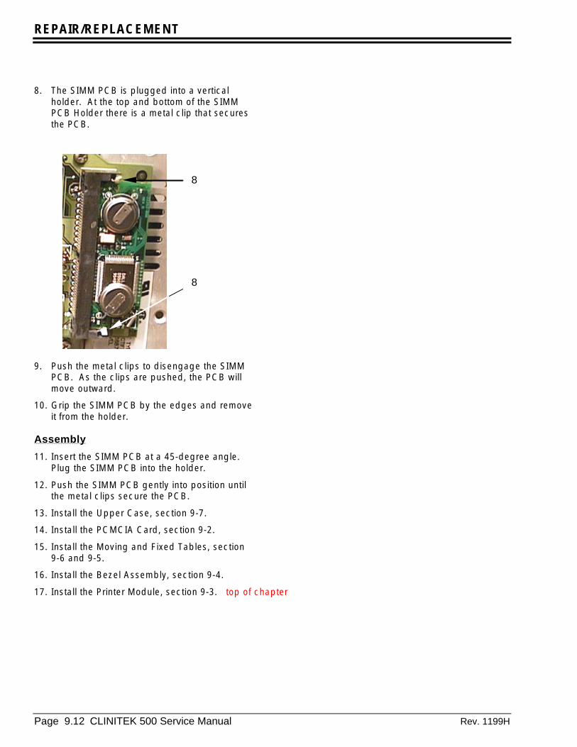
REPAIR/REPLACEMENT
Page 9.12 CLINITEK 500 Service Manual Rev. 1199H
8. The SIMM PCB is plugged into a verticalholder. At the top and bottom of the SIMMPCB Holder there is a metal clip that securesthe PCB.
9. Push the metal clips to disengage the SIMMPCB. As the clips are pushed, the PCB willmove outward.
10. Grip the SIMM PCB by the edges and removeit from the holder.
Assembly
11. Insert the SIMM PCB at a 45-degree angle.Plug the SIMM PCB into the holder.
12. Push the SIMM PCB gently into position untilthe metal clips secure the PCB.
13. Install the Upper Case, section 9-7.
14. Install the PCMCIA Card, section 9-2.
15. Install the Moving and Fixed Tables, section9-6 and 9-5.
16. Install the Bezel Assembly, section 9-4.
17. Install the Printer Module, section 9-3. top of chapter
8
8

REPAIR/REPLACEMENT
Rev.1199H CLINITEK 500 Service Manual 9.13
9-12 Electronics BracketDis/Assembly
Tools required:• #2 Phillips screwdriver for M4 screws, all
others use a #1 Phillips screwdriver• Torque Driver
Disassembly
1. Remove the PCMCIA Card, section 9-2.
2. Remove the Printer Module section 9-3.
3. Remove the Bezel Assembly,section 9-4.
4. Remove the Fixed Table, section 9-5.
5. Remove the Upper Case, section 9-7.
6. Unplug the Strip Detector cable (J6) and thecable coming from the A/D PCB (J2) from theProcessor PCB. Also disconnect the powercable going to the Printer Interface PCB fromthe Mother PCB at connector P7 on theMother PCB.
7. From the rear of the instrument, remove onescrew on left side securing the bracket to theLower Case. This screw goes through agrounding strap.
8. Loosen the two screws on the right side.
Note
These screws are designed to stay with theassembly when they are unscrewed. As they areloosened, an inner spring pushes them upward.Once they are loose, just leave them seated inhole
a. The first screw is located next to thePower Supply on the inside.
b. One screw is at the right rear of thebracket, next to the main power plug
7
8a
8b
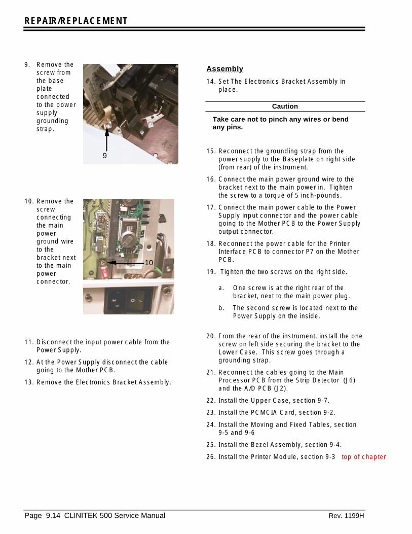
REPAIR/REPLACEMENT
Page 9.14 CLINITEK 500 Service Manual Rev. 1199H
9. Remove thescrew fromthe baseplateconnectedto the powersupplygroundingstrap.
10. Remove thescrewconnectingthe mainpowerground wireto thebracket nextto the mainpowerconnector.
11. Disconnect the input power cable from thePower Supply.
12. At the Power Supply disconnect the cablegoing to the Mother PCB.
13. Remove the Electronics Bracket Assembly.
Assembly
14. Set The Electronics Bracket Assembly inplace.
Caution
Take care not to pinch any wires or bendany pins.
15. Reconnect the grounding strap from thepower supply to the Baseplate on right side(from rear) of the instrument.
16. Connect the main power ground wire to thebracket next to the main power in. Tightenthe screw to a torque of 5 inch-pounds.
17. Connect the main power cable to the PowerSupply input connector and the power cablegoing to the Mother PCB to the Power Supplyoutput connector.
18. Reconnect the power cable for the PrinterInterface PCB to connector P7 on the MotherPCB.
19. Tighten the two screws on the right side.
a. One screw is at the right rear of thebracket, next to the main power plug.
b. The second screw is located next to thePower Supply on the inside.
20. From the rear of the instrument, install the onescrew on left side securing the bracket to theLower Case. This screw goes through agrounding strap.
21. Reconnect the cables going to the MainProcessor PCB from the Strip Detector (J6)and the A/D PCB (J2).
22. Install the Upper Case, section 9-7.
23. Install the PCMCIA Card, section 9-2.
24. Install the Moving and Fixed Tables, section9-5 and 9-6
25. Install the Bezel Assembly, section 9-4.
26. Install the Printer Module, section 9-3 top of chapter
10
9
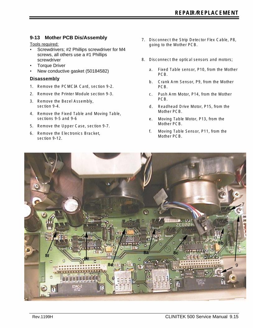
REPAIR/REPLACEMENT
Rev.1199H CLINITEK 500 Service Manual 9.15
9-13 Mother PCB Dis/AssemblyTools required:• Screwdrivers; #2 Phillips screwdriver for M4
screws, all others use a #1 Phillipsscrewdriver
• Torque Driver• New conductive gasket (50184582)
Disassembly
1. Remove the PCMCIA Card, section 9-2.
2. Remove the Printer Module section 9-3.
3. Remove the Bezel Assembly,section 9-4.
4. Remove the Fixed Table and Moving Table,sections 9-5 and 9-6
5. Remove the Upper Case, section 9-7.
6. Remove the Electronics Bracket,section 9-12.
7. Disconnect the Strip Detector Flex Cable, P8,going to the Mother PCB.
8. Disconnect the optical sensors and motors;
a. Fixed Table sensor, P10, from the MotherPCB.
b. Crank Arm Sensor, P9, from the MotherPCB.
c. Push Arm Motor, P14, from the MotherPCB.
d. Readhead Drive Motor, P15, from theMother PCB.
e. Moving Table Motor, P13, from theMother PCB.
f. Moving Table Sensor, P11, from theMother PCB.
8a
8b
8c8e
8d
8f
7
9
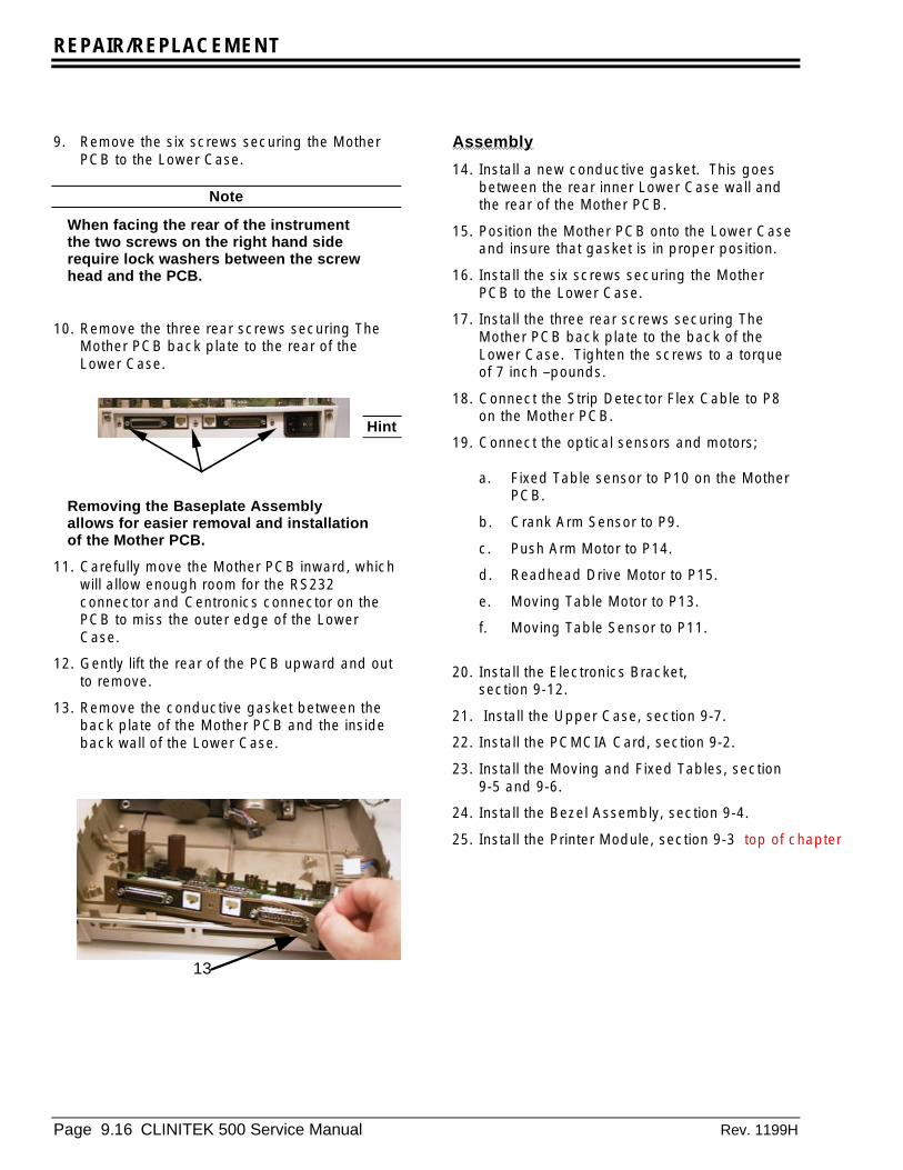
REPAIR/REPLACEMENT
Page 9.16 CLINITEK 500 Service Manual Rev. 1199H
9. Remove the six screws securing the MotherPCB to the Lower Case.
Note
When facing the rear of the instrumentthe two screws on the right hand siderequire lock washers between the screwhead and the PCB.
10. Remove the three rear screws securing TheMother PCB back plate to the rear of theLower Case.
Hint
Removing the Baseplate Assemblyallows for easier removal and installationof the Mother PCB.
11. Carefully move the Mother PCB inward, whichwill allow enough room for the RS232connector and Centronics connector on thePCB to miss the outer edge of the LowerCase.
12. Gently lift the rear of the PCB upward and outto remove.
13. Remove the conductive gasket between theback plate of the Mother PCB and the insideback wall of the Lower Case.
Assembly
14. Install a new conductive gasket. This goesbetween the rear inner Lower Case wall andthe rear of the Mother PCB.
15. Position the Mother PCB onto the Lower Caseand insure that gasket is in proper position.
16. Install the six screws securing the MotherPCB to the Lower Case.
17. Install the three rear screws securing TheMother PCB back plate to the back of theLower Case. Tighten the screws to a torqueof 7 inch –pounds.
18. Connect the Strip Detector Flex Cable to P8on the Mother PCB.
19. Connect the optical sensors and motors;
a. Fixed Table sensor to P10 on the MotherPCB.
b. Crank Arm Sensor to P9.
c. Push Arm Motor to P14.
d. Readhead Drive Motor to P15.
e. Moving Table Motor to P13.
f. Moving Table Sensor to P11.
20. Install the Electronics Bracket,section 9-12.
21. Install the Upper Case, section 9-7.
22. Install the PCMCIA Card, section 9-2.
23. Install the Moving and Fixed Tables, section9-5 and 9-6.
24. Install the Bezel Assembly, section 9-4.
25. Install the Printer Module, section 9-3 top of chapter
13

REPAIR/REPLACEMENT
Rev.1199H CLINITEK 500 Service Manual 9.17
9-14 Strip Detector Dis/AssemblyTools required:• Screwdrivers; #2 Phillips screwdriver for M4
screws, all others use a #1 Phillipsscrewdriver
• Right angle Phillips screwdriver screwdriverDisassembly1. Remove the PCMCIA Card, section 9-2.
2. Remove the Printer Module section 9-34.
3. Remove the Bezel Assembly,section 9-4.
4. Remove the Fixed Table, section 9-5.
5. Remove the Upper Case, section 9-7.
6. Disconnect the detector flex cable from J6 onthe top left side of the Processor PCB.
7. Disconnect the detector flex cable from P8 on
the Mother PCB.
8. Using a right angle Phillips screwdriverscrewdriver, remove the two Phillipsscrewdriver head screws holding the StripDetector Bracket to the casting.
Note
To gain access to the left-hand detectorscrew , remove the top securing screwfrom the Power Supply. This allows thePower Supply to be moved to the left togain access to the detector screw.
Hint
8A. An alternative to removing the bracket is toremove the Strip Detector PCB from the bracket.Removing the two Phillips screwdriver screws thatsecure it to the Bracket accomplishes this.
9. Remove the Strip Detector Assembly.
Assembly
10. Install the Strip Detector Assembly with theflex cable at the bottom of strip. The bracketmust fit in to the ledge on the casting.
Note
The Strip Detector Housing Assembly(black piece covering detectors) is keyedat one end.
11. Install the two Phillips screwdriver headscrews holding the Strip Detector Bracket tothe casting.
12. Connect the 5-pin flex cable P8 on the MotherPCB.
Note
For ease of connecting other cables,connect the 5-pin flex cable first.
13. Connect the 12-pin flex cable to J6 on theProcessor PCB.
14. Install the Upper Case, section 9-7.
15. Install the PCMCIA Card, section 9-2.
16. Install the Moving and Fixed Tables, sections9-6 and 9-5.
8
8A
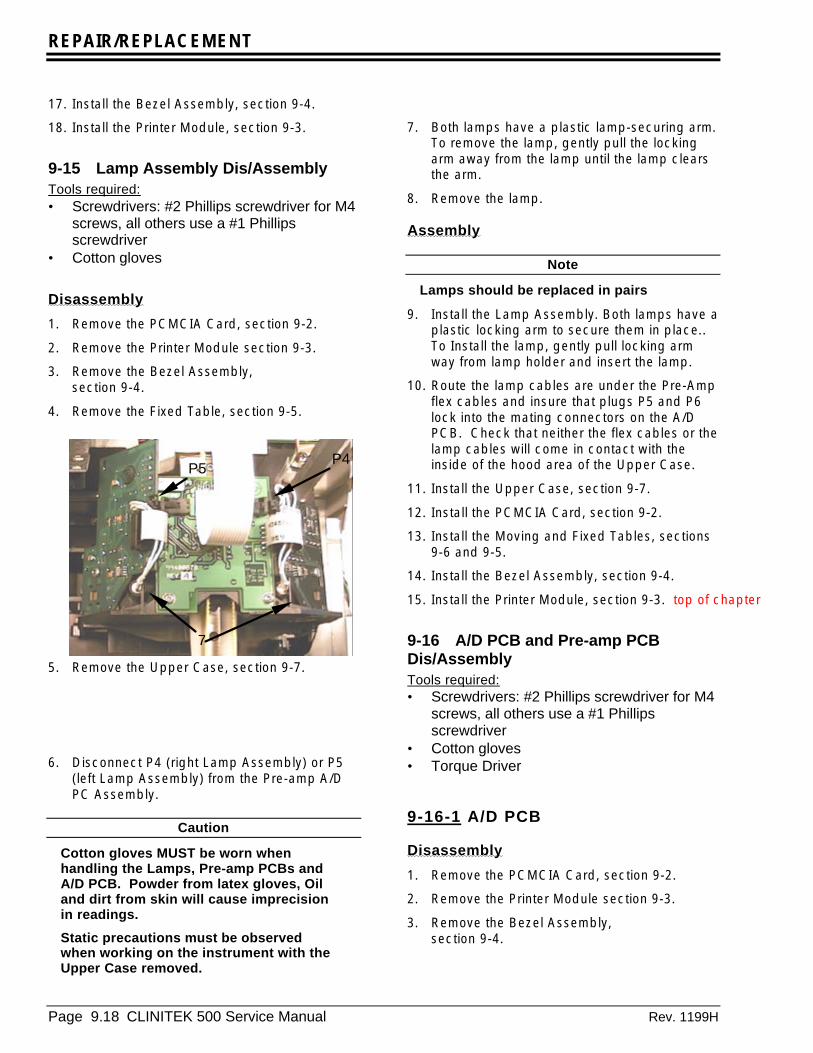
REPAIR/REPLACEMENT
Page 9.18 CLINITEK 500 Service Manual Rev. 1199H
17. Install the Bezel Assembly, section 9-4.
18. Install the Printer Module, section 9-3.
9-15 Lamp Assembly Dis/AssemblyTools required:• Screwdrivers: #2 Phillips screwdriver for M4
screws, all others use a #1 Phillipsscrewdriver
• Cotton gloves
Disassembly
1. Remove the PCMCIA Card, section 9-2.
2. Remove the Printer Module section 9-3.
3. Remove the Bezel Assembly,section 9-4.
4. Remove the Fixed Table, section 9-5.
5. Remove the Upper Case, section 9-7.
6. Disconnect P4 (right Lamp Assembly) or P5(left Lamp Assembly) from the Pre-amp A/DPC Assembly.
Caution
Cotton gloves MUST be worn whenhandling the Lamps, Pre-amp PCBs andA/D PCB. Powder from latex gloves, Oiland dirt from skin will cause imprecisionin readings.
Static precautions must be observedwhen working on the instrument with theUpper Case removed.
7. Both lamps have a plastic lamp-securing arm.To remove the lamp, gently pull the lockingarm away from the lamp until the lamp clearsthe arm.
8. Remove the lamp.
Assembly
Note
Lamps should be replaced in pairs
9. Install the Lamp Assembly. Both lamps have aplastic locking arm to secure them in place..To Install the lamp, gently pull locking armway from lamp holder and insert the lamp.
10. Route the lamp cables are under the Pre-Ampflex cables and insure that plugs P5 and P6lock into the mating connectors on the A/DPCB. Check that neither the flex cables or thelamp cables will come in contact with theinside of the hood area of the Upper Case.
11. Install the Upper Case, section 9-7.
12. Install the PCMCIA Card, section 9-2.
13. Install the Moving and Fixed Tables, sections9-6 and 9-5.
14. Install the Bezel Assembly, section 9-4.
15. Install the Printer Module, section 9-3. top of chapter
9-16 A/D PCB and Pre-amp PCBDis/AssemblyTools required:• Screwdrivers: #2 Phillips screwdriver for M4
screws, all others use a #1 Phillipsscrewdriver
• Cotton gloves• Torque Driver
9-16-1 A/D PCB
Disassembly
1. Remove the PCMCIA Card, section 9-2.
2. Remove the Printer Module section 9-3.
3. Remove the Bezel Assembly,section 9-4.
P5P4
7

REPAIR/REPLACEMENT
Rev.1199H CLINITEK 500 Service Manual 9.19
4. Remove the Fixed and Moving Tables, section9-5 and 9-6.
5. Remove the Upper Case, section 9-7.
6. Disconnect P4 (right Lamp Assembly) & P5(left Lamp Assembly) from the Pre-amp A/DPC Assembly.
7. Both lamps have a plastic securing arm. Toremove the lamp, gently pull locking armaway from lamp until the lamp clears the arm.
8. Remove the lamps.
9. Disconnect the flex cable from J2 on theProcessor PCB.
10. Disconnect the flex cables from the left andright Pre-amp PCB. Lifting the outer housingof the ZIF connector will unlock it allowing theflex cable to be removed.
11. Remove the two screws securing the Pre-amp A/D Interconnect PCB to “Readhead.Also remove the cable and foam from thesecuring clip on the electronics bracket.
Assembly
12. Set Pre-amp A/D on top of Readhead CarrierAssembly and align the screw holes.
13. Install the two screws securing the Pre-ampA/D to “Readhead Carrier Assembly” andtighten to a torque of 7 inch-pounds.
14. Connect the 12-pin flex cable to J2 onProcessor PCB and re-rout the cable neatlythrough the cable clip.
15. Install the Lamp Assembly’s,section 9-15.
16. Connect the lamp connectors P4 and P5 toPre-amp A/D Interconnect PCB Assembly.Install the Flex cables into the ZIF connectoron the Pre-amp PCBs.
17. Install the Upper Case, section 9-7.
18. Install the PCMCIA Card, section 9-2.
19. Install the Moving and Fixed Tables, sections9-6 and 9-5.
20. Install the Bezel Assembly, section 9-4.
21. Install the Printer Module, section 9-3. top of chapter
P5P4
7
11
11 11

REPAIR/REPLACEMENT
Page 9.20 CLINITEK 500 Service Manual Rev. 1199H
9-16-2 Pre-amp PCBs
Note
It is easier to remove and install the Pre-amp PCBs with the A/D PCB removed.
Tools required:• Screwdrivers: #2 Phillips screwdriver for M4
screws, all others use a #1 Phillipsscrewdriver
• Cotton gloves• Torque Driver
Caution
Cotton gloves MUST be worn whenhandling the Lamps, Pre-amp PCBs andA/D PCB. Powder from latex gloves, Oiland dirt from skin will cause imprecisionin readings.
Static precautions must be observedwhen working on the instrument with theUpper Case removed.
Disassembly
1. The Pre-amp PCBs are attached to the blackplastic readhead body by one screw (1A) andtwo tabs molded into the readhead (1B) (Seephotos of the Left and Right Pre-amps).Removing the screw allows the Pre-amp PCBsto be separated from the readhead body.
CAUTION
When removing or installing the screwwhich secures the Pre-amp PCBs, thereadhead body must be supported fromunderneath to prevent it from breaking.
Right Pre-Amp
1A
1B
Left Pre-Amp PCB
1A
1B

REPAIR/REPLACEMENT
Rev.1199H CLINITEK 500 Service Manual 9.21
Assembly2. Move the readhead body to the front of the
instrument.
3. Position the Pre-amp PCB in place and fastenwith the screw. Tighten the screw to a torqueof 7 inch-pounds.
Note
Make sure that the left Pre-amp PCB doesnot “Droop”. If the rear of the PCB hangsdown it may run into the Slider Arm (seeBaseplate assembly in the chapter 10).
4. Reconnect the flex cables coming from theA/D PCB and continue with the assemblyprocedure for the A/D PCB fromsection 9-16-1.
HINT
You may find it easier to install the flexcables from the A/D PCB into the Pre-amps before installing any of the PCBsonto the readhead body. You can theninstall the three PCB assembly startingwith the Left Pre-amp, next the A/D PCBand finishing with the Right Pre-ampPCB. top of chapter
9-17 Drive Housing Dis/AssemblyTools required:• Screwdrivers: #2 Phillips screwdriver for M4
screws, all others use a #1 Phillipsscrewdriver
• Hex wrench 5/64
Disassembly
1. Remove the PCMCIA Card, section 9-2.
2. Remove the Printer Module section 9-3.
3. Remove the Bezel Assembly,section 9-4.
4. Remove the Fixed and Moving Tables,sections 9-5 and 9-6.
5. Remove the Upper Case, section 9-7.
6. Remove the Left Table Guide Assembly,section 9-8.
7. Move the Readhead Carrier Assembly to therear position on the instrument.
8. Remove the two Phillips screwdriver headscrews securing the Drive Housing on the leftand two screws on right.
9. Disconnect the optical sensor from TheMother PCB.
Coupling
9

REPAIR/REPLACEMENT
Page 9.22 CLINITEK 500 Service Manual Rev. 1199H
Note
A Flexible Coupling connects the DriveHousing Assembly to the stepper motorshaft.
Hint
You may find it necessary to loosen onehalf of the Flexible coupling to removethe Drive Housing assembly. To do this:
Rotate the coupling so that the setscrewsare at the 1 o’clock position.
Use a 5/64 Hex wrench to loosen thesetscrew of the coupling on the shaftcoming from the Drive Housingassembly.
Slide that half of the coupling towardsthe Drive Housing assembly on the shaft.
Caution
On the bottom of the Drive HousingAssembly, there are two pins that key thehousing into the Baseplate. The housingmust gently be lifted upward todisengage these pins.
Do not use the front rotating plate of theDrive Housing for lifting, use the sides ofthe Drive Housing.
10. Gently lift the left side of the housing upwarduntil you feel the left tab come out of theBaseplate hole.
11. Holding the left side of the housing with yourleft hand, place your right hand on the rightside of the housing. Gently lift upward withyour right hand while gently twisting upwardwith your left hand.
12. Remove the housing and guide the opticalsensor cable through the hole in the righttable guide.
Assembly
13. Guide the optical sensor wire through the holein the side of the Right-hand Table Guidedirectly above the screws holding the sensoronto the Table Guide.
14. Slide the housing gear into the FlexibleCoupler.
Caution
Do not push on the Moving Table Plate.
15. Holding the left side of the housing with yourleft hand, push on the right side of thehousing until the right tab falls into theBaseplate positioning hole. When the rightside is in, push on left side of housing untilyou feel the left side fall into position.
16. Make sure that the table sensor flag iscentered between the sensor arms.
17. Plug the sensor wire into P11 on the MotherPCB.
18. Install the two Phillips screwdriver headscrews securing the Drive Housing on the leftand two screws on right.
19. Install the Left Table Guide Assembly, section9-8.
20. Install the Upper Case, section 9-7.
21. Install the PCMCIA Card, section 9-2.
22. Install the Moving and Fixed Tables, sections9-6 and 9-5.
23. Install the Bezel Assembly, section 9-4.
24. Install the Printer Module, section 9-3.
25. Perform strip centering setup and the stripwalk test. top of chapter

REPAIR/REPLACEMENT
Rev.1199H CLINITEK 500 Service Manual 9.23
9-18 Crank Arm Dis/AssemblyTools required:• Screwdrivers: #2 Phillips screwdriver for M4
screws, all others use a #1 Phillipsscrewdriver
• .050 inch Hex wrench• Torque Driver
Disassembly
1. Remove the PCMCIA Card, section 9-2.
2. Remove the Printer Module section 9-3.
3. Remove the Bezel Assembly,section 9-4.
4. Remove the Fixed Table, section 9-5.
5. Remove the Moving Table, section 9-6.
6. Remove the Upper Case, section 9-7.
7. Move the Readhead to the front of theinstrument.
8. Rotate the Crank Arm so that it points to theright side of the instrument. This will alsomove the Slider Arm to the right.
Note
Refer to the Baseplate Assembly in theillustrated parts break down.
9. Remove the Phillips screwdriver head screwwhich holds the Shaft in place.
10. Slide the shaft to the left.
11. Tilt the Slide Arm forward (to clear the StripDetector assembly) and lift up. This willremove the Slide Arm from the instrument
12. Loosen the set screw (now located at the 12O-clock position) with the “short arm” of a.050 inch Hex wrench.
13. Pull the Crank Arm off the Push Arm DriveMotor Shaft.
Assembly
14. Push the Crank Arm onto the Push Arm DriveMotor shaft. Align the flat spot of the CrankArm with the flat spot of the motor shaft.
15. Align front of motor shaft with front of CrankArm.
16. Tighten setscrew..
17. Position the Slider Arm so that it engages theGuide Rail on the Baseplate and that the Shaftis aligned with its hole.
18. Slide the Shaft through the Slider Arm andinto its support on the Motor Casting. Installthe lock washer and Phillips screwdriver headscrew to secure the Shaft in place. Tightenthe screw to 8 inch pounds of torque.
Note
Grease is to be applied to the shaft.Reference section 5 for greasing shaft.
19. Install the Upper Case, section 9-7.
20. Install the PCMCIA Card, section 9-2.
21. Install the Moving Table, section 9-6
22. . Install the Fixed Table, section 9-5.
23. Install the Bezel Assembly, section 9-4.
24. Install the Printer Module, section 9-3. top of chapter
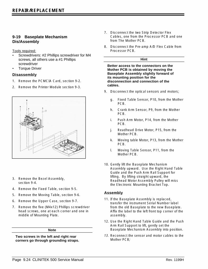
REPAIR/REPLACEMENT
Page 9.24 CLINITEK 500 Service Manual Rev. 1199H
9-19 Baseplate MechanismDis/Assembly
Tools required:• Screwdrivers: #2 Phillips screwdriver for M4
screws, all others use a #1 Phillipsscrewdriver
• Torque Driver
Disassembly
1. Remove the PCMCIA Card, section 9-2.
2. Remove the Printer Module section 9-3.
3. Remove the Bezel Assembly,section 9-4.
4. Remove the Fixed Table, section 9-5.
5. Remove the Moving Table, section 9-6.
6. Remove the Upper Case, section 9-7.
7. Remove the five (M4x12) Phillips screwdriverhead screws, one at each corner and one inmiddle of Mounting Plate.
Note
Two screws in the left and right rearcorners go through grounding straps.
7. Disconnect the two Strip Detector FlexCables, one from the Processor PCB and onefrom The Mother PCB.
8. Disconnect the Pre-amp A/D Flex Cable fromProcessor PCB.
Hint
Better access to the connectors on theMother PCB is obtained by moving theBaseplate Assembly slightly forward ofits mounting position for thedisconnection and connection of thecables.
9. Disconnect the optical sensors and motors;
g. Fixed Table Sensor, P10, from the MotherPCB.
h. Crank Arm Sensor, P9, from the MotherPCB.
i. Push Arm Motor, P14, from the MotherPCB.
j. Readhead Drive Motor, P15, from theMother PCB.
k. Moving table Motor, P13, from the MotherPCB.
l. Moving Table Sensor, P11, from theMother PCB.
10. Gently lift the Baseplate MechanismAssembly upward. Use the Right Hand TableGuide and the Push Arm Rail Support forlifting. By lifting straight upward, theReadhead Motor Assembly Pulley will missthe Electronic Mounting Bracket Top.
Assembly
11. If the Baseplate Assembly is replaced,transfer the instrument Serial Number labelfrom the old Baseplate to the new Baseplate.Affix the label to the left front top corner of theassembly.
12. Use the Right Hand Table Guide and the PushArm Rail Support to lift, gently set theBaseplate Mechanism Assembly into position.
13. Reconnect the sensor and motor cables to theMother PCB;
REPAIR/REPLACEMENT
Rev.1199H CLINITEK 500 Service Manual 9.25
14. Fixed Table Sensor, P10, to The Mother PCB.
15. Crank Arm Sensor, P9, to The Mother PCB.
16. Push Arm Motor, P14, to The Mother PCB.
17. Readhead Drive Motor, P15, to The MotherPCB.
18. Moving table Motor, P13, to The Mother PCB.
19. Moving Table Sensor, P11, to The MotherPCB.
20. Connect the Pre-amp A/D Flex Cable toProcessor PCB.
21. Connect the two Strip Detector Flex Cables,P1 to P8 on The Mother PCB and P2 to J6 onProcessor PCB.
22. Install the five (M4x12) Phillips screwdriverhead screws. One at each corner and one inmiddle of Mounting Plate. The screws shouldbe tightened to a torque of 18 inch poundsand 12 inch pounds for the ground strap atthe card.
23. Install the Upper Case, section 9-7.
24. Install the PCMCIA Card, section 9-2.
25. Install the Moving and Fixed Tables, sections9-6and 9-5.
26. Install the Bezel Assembly, section 9-4.
27. Install the Printer Module, section 9-3. top of chapter
REPAIR/REPLACEMENT
Page 9.26 CLINITEK 500 Service Manual Rev. 1199H
9-20 Lower Case Dis/Assembly
Tools required:• #2 Phillips screwdriver for M4 screws, all
others use a #1 Phillips screwdriver• Torque Driver
Disassembly
1. Remove the PCMCIA Card, section 9-2.
2. Remove the Printer Module section 9-3.
3. Remove the Bezel Assembly, section 9-4.
4. Remove the Fixed Table, section 9-5.
5. Remove the Moving Table, section 9-6.
6. Remove the Upper Case, section 9-7.
7. Remove the Electronics Bracket, section 9-12
8. Remove the Baseplate Mechanism, section 9-19.
9. Remove the Mother PCB, section 9-13.
Assembly
10. Position The Mother PCB onto the LowerCase.
11. Install the six screws securing The MotherPCB to the Lower Case.
12. Install the three rear screws securing theMother PCB back plate and new conductiveGasket to back of Lower Case. Tighten thescrews to a torque of 7 inch-pounds.
13. Use the Right Hand Table Guide and the PushArm Rail Support to lift, gently set theBaseplate Mechanism Assembly into position.
Note
Before setting assembly in place securethe wires and cables so as not to be inthe way.
14. Install the three (M4x12) Phillips screwdriverhead screws. One at each front corner andone in middle of Mounting Plate.
15. Connect the optical sensors and motors;
16. Fixed Table Sensor, P10, to The Mother PCB.
17. Crank Arm Sensor, P9, to The Mother PCB.
18. Push Arm Motor, P14, to The Mother PCB.
19. Readhead Drive Motor, P15, to The MotherPCB.
20. Moving table Motor, P13, to The Mother PCB.
21. Moving Table Sensor, P11, to The MotherPCB.
22. Plug in the Strip Detector cable into theMother PCB.
23. Set Electronics Bracket in place.
24. Connect the main power ground wire to thebracket next to the main power in.
25. Connect the main power cable to The PowerSupply.
26. Connect the Power Supply connector J12 toconnector P12 on The Mother PCB.
27. Tighten two screws on right side. One screwis at the right rear of the bracket, next to themain power plug. The second screw islocated next to the Power Supply on theinside.
28. Install the Phillips screwdriver head screw onthe grounding strap at lower front of ThePower Supply.
29. From the rear of the instrument, Install the onescrew on left side securing the bracket to theLower Case. This screw goes through agrounding strap (tighten to 12 inch pounds).
30. Other end of grounding strap is screwed tothe Baseplate Mechanism.
31. Swivel the instrument so front is facing you.
32. Connect the Strip Detector to J6 on top leftside of Processor PCB
33. Connect the Printer Interface PCB powercable to P7 located on the Mother PCB.
34. Connect the Pre-amp A/D to J2 on top rightside of Processor PCB.
35. Install the Upper Case, section 9-7.
36. Install the Moving Table, section 9-6.
37. Install the Fixed Tables, section 9-5.
38. Install the Bezel Assembly, section 9-4.
39. Install the Printer Module, section 9-3.
40. Install the PCMCIA Card, section 9-2. top of chapter
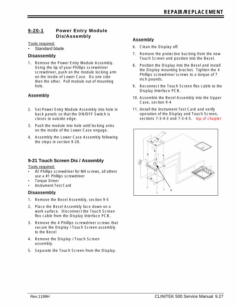
REPAIR/REPLACEMENT
Rev.1199H CLINITEK 500 Service Manual 9.27
9-20-1 Power Entry ModuleDis/Assembly
Tools required:• Standard blade
Disassembly
1. Remove the Power Entry Module Assembly.Using the tip of your Phillips screwdriverscrewdriver, push on the module locking armon the inside of Lower Case. Do one sidethen the other. Pull module out of mountinghole.
Assembly
2. Set Power Entry Module Assembly into hole inback panels so that the ON/OFF Switch iscloses to outside edge.
3. Push the module into hole until locking armson the inside of the Lower Case engage.
4. Assembly the Lower Case Assembly followingthe steps in section 9-20.
9-21 Touch Screen Dis / AssemblyTools required:• #2 Phillips screwdriver for M4 screws, all others
use a #1 Phillips screwdriver• Torque Driver• Instrument Test Card
Disassembly
1. Remove the Bezel Assembly, section 9-5
2. Place the Bezel Assembly face down on awork surface. Disconnect the Touch Screenflex cable from the Display Interface PCB.
3. Remove the 4 Phillips screwdriver screws thatsecure the Display / Touch Screen assemblyto the Bezel
4. Remove the Display / Touch Screenassembly.
5. Separate the Touch Screen from the Display.
Assembly
6. Clean the Display off.
7. Remove the protective backing from the newTouch Screen and position into the Bezel.
8. Position the Display into the Bezel and installthe Display mounting bracket. Tighten the 4Phillips screwdriver screws to a torque of 7inch pounds.
9. Reconnect the Touch Screen flex cable to theDisplay Interface PCB.
10. Assemble the Bezel Assembly into the UpperCase, section 9-4
11. Install the Instrument Test Card and verifyoperation of the Display and Touch Screen,sections 7-3-4-3 and 7-3-4-5. top of chapter
5
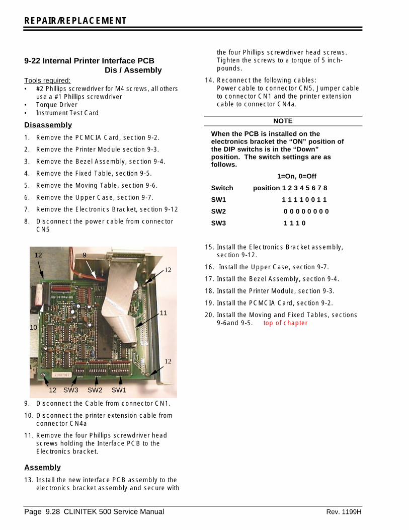
REPAIR/REPLACEMENT
Page 9.28 CLINITEK 500 Service Manual Rev. 1199H
9-22 Internal Printer Interface PCB Dis / AssemblyTools required:• #2 Phillips screwdriver for M4 screws, all others
use a #1 Phillips screwdriver• Torque Driver• Instrument Test Card
Disassembly
1. Remove the PCMCIA Card, section 9-2.
2. Remove the Printer Module section 9-3.
3. Remove the Bezel Assembly, section 9-4.
4. Remove the Fixed Table, section 9-5.
5. Remove the Moving Table, section 9-6.
6. Remove the Upper Case, section 9-7.
7. Remove the Electronics Bracket, section 9-12
8. Disconnect the power cable from connectorCN5
9. Disconnect the Cable from connector CN1.
10. Disconnect the printer extension cable fromconnector CN4a
11. Remove the four Phillips screwdriver headscrews holding the Interface PCB to theElectronics bracket.
Assembly
13. Install the new interface PCB assembly to theelectronics bracket assembly and secure with
the four Phillips screwdriver head screws.Tighten the screws to a torque of 5 inch-pounds.
14. Reconnect the following cables:Power cable to connector CN5, Jumper cableto connector CN1 and the printer extensioncable to connector CN4a.
NOTE
When the PCB is installed on theelectronics bracket the “ON” position ofthe DIP switchs is in the “Down”position. The switch settings are asfollows.
1=On, 0=Off
Switch position 1 2 3 4 5 6 7 8
SW1 1 1 1 1 0 0 1 1
SW2 0 0 0 0 0 0 0 0
SW3 1 1 1 0
15. Install the Electronics Bracket assembly,section 9-12.
16. Install the Upper Case, section 9-7.
17. Install the Bezel Assembly, section 9-4.
18. Install the Printer Module, section 9-3.
19. Install the PCMCIA Card, section 9-2.
20. Install the Moving and Fixed Tables, sections9-6and 9-5. top of chapter
SW3 SW2 SW1
9
10
11
12
12
12
12

ILLUSTRATED PARTS BREAKDOWN
Rev. 1199H CLINITEK 500 Service Manual Page 10.1
CHAPTER TEN - ILLUSTRATED PARTS BREAKDOWN Return
Title Page
Upper Case Assembly------------------------------------------------------------------------ 10.3Exploded View Part 1-------------------------------------------------------------------------- 10.4Exploded View Part 2-------------------------------------------------------------------------- 10.5Base Plate Assembly Part !------------------------------------------------------------------- 10.6Base Plate Assembly Part 2------------------------------------------------------------------- 10.7Readhead Assembly---------------------------------------------------------------------------- 10.8Electronics Bracket Assembly----------------------------------------------------------------- 10.9Lower Case Assembly-------------------------------------------------------------------------- 10.10Drive Housing Assembly----------------------------------------------------------------------- 10.11Power Cable Assembly------------------------------------------------------------------------- 10.12Cable Assembly Printer Power--------------------------------------------------------------- 10.13Optical Interrupter Assembly----------------------------------------------------------------- 10.14Fixed Table Assembly and Holddown------------------------------------------------------ 10.15Bare Code Reader Cable---------------------------------------------------------------------- 10.16Motor Casting Assembly----------------------------------------------------------------------- 10.17Display Bezel Assembly----------------------------------------------------------------------- 10.18Horizontal Plate Alignment Fixture---------------------------------------------------------- 10.19

ILLUSTRATED PARTS BREAKDOWN
Page 10.2 CLINTEK 500 Service Manual Rev. 1199H
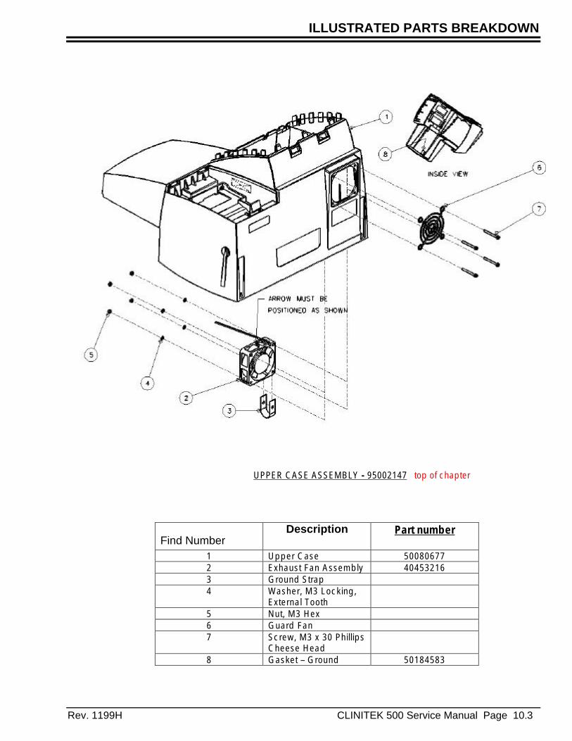
ILLUSTRATED PARTS BREAKDOWN
Rev. 1199H CLINITEK 500 Service Manual Page 10.3
Find NumberDescription Part number
1 Upper Case 500806772 Exhaust Fan Assembly 404532163 Ground Strap4 Washer, M3 Locking,
External Tooth5 Nut, M3 Hex6 Guard Fan7 Screw, M3 x 30 Phillips
Cheese Head8 Gasket – Ground 50184583
UPPER CASE ASSEMBLY - 95002147 top of chapter
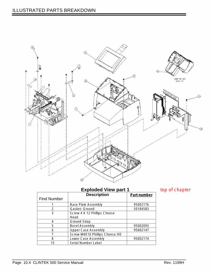
ILLUSTRATED PARTS BREAKDOWN
Page 10.4 CLINTEK 500 Service Manual Rev. 1199H
Find NumberDescription Part number
1 Base Plate Assembly 950021762 Gasket- Ground 501845833 Screw 4 X 12 Phillips Cheese
Head4 Ground Strap5 Bezel Assembly 950020936 Upper Case Assembly 950021477 Screw M4X10 Phillips Cheesa HD8 Lower Case Assembly 9500217415 Serial Number Label
Exploded View part 1 top of chapter

ILLUSTRATED PARTS BREAKDOWN
Rev. 1199H CLINITEK 500 Service Manual Page 10.5
.
..
Find NumberDescription Part number
7 Screw M4X10 Phillips Cheesa HD8 Lower Case Assembly 9500217410 Electronics Bracket Assembly 9500214811 Shield Printer 5055109812 Tape- Foam13 Printer Cover 5006231914 Printer Thermal 4045101216 Label- UL / CSA / TUV / EMC / CE 5034072617 Rating Label18 Screw M3 X 8 Phillips Cheese HD
Not shown Conductive Gasket for MotherP.C.B.
50184582
Exploded View part 2 top of chapter

ILLUSTRATED PARTS BREAKDOWN
Page 10.6 CLINTEK 500 Service Manual Rev. 1199H
1
234
5
6
Find Number Description Part Number1 Right Table Guide 950020882 Drive Housing Assembly 950020663 Left Table Guide 950020894 Fixed Table Sensor 404532225 Push Arm Home sensor 404532336 Strip Detector Assembly 950021757 Lamp 40453220
Base Plate Assembly 1 top of chapter
7
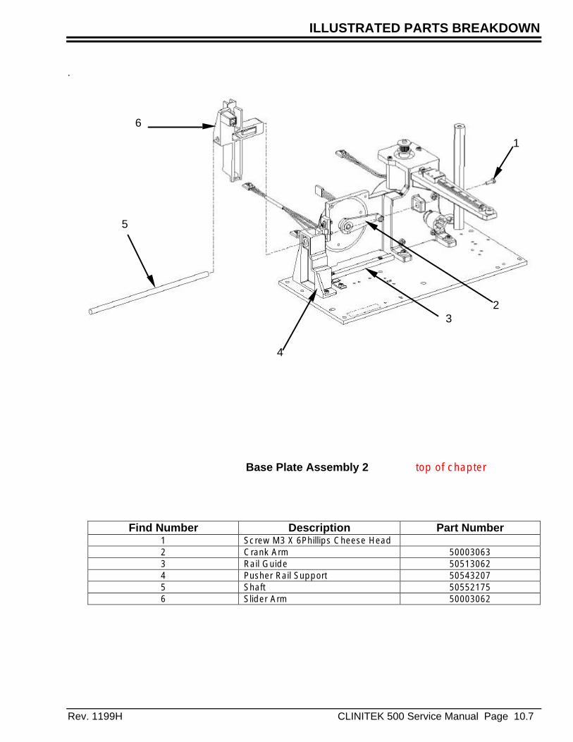
ILLUSTRATED PARTS BREAKDOWN
Rev. 1199H CLINITEK 500 Service Manual Page 10.7
.
1
23
4
5
6
Base Plate Assembly 2 top of chapter
Find Number Description Part Number1 Screw M3 X 6Phillips Cheese Head2 Crank Arm 500030633 Rail Guide 505130624 Pusher Rail Support 505432075 Shaft 505521756 Slider Arm 50003062
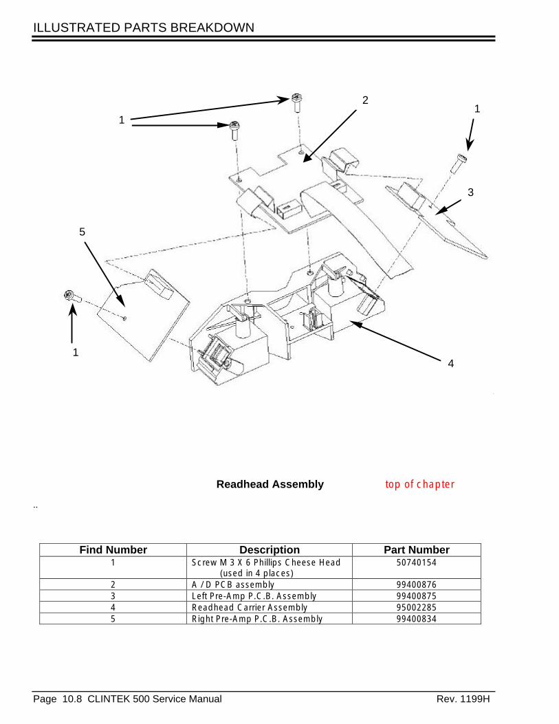
ILLUSTRATED PARTS BREAKDOWN
Page 10.8 CLINTEK 500 Service Manual Rev. 1199H
..
Readhead Assembly top of chapter
Find Number Description Part Number1 Screw M 3 X 6 Phillips Cheese Head
(used in 4 places)50740154
2 A / D PCB assembly 994008763 Left Pre-Amp P.C.B. Assembly 994008754 Readhead Carrier Assembly 950022855 Right Pre-Amp P.C.B. Assembly 99400834
1
2
3
4
5
1
1

ILLUSTRATED PARTS BREAKDOWN
Rev. 1199H CLINITEK 500 Service Manual Page 10.9
..
Find Number Description Part Number1 Bracket Mounting 500325752 Printer Interface PCB Assembly 994008333 Cable Assembly Printer Interface
Power40453027
4 Cable Assembly Jumper 20 Pin 404532255 Power Supply 404532176 Cable Assembly
Power Supply / Mother PCB40453218
7 Cable Assembly Printer Extension 40453234
Electronics Bracket Assembly top of chapter
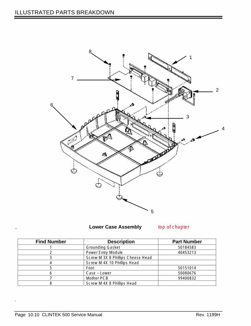
ILLUSTRATED PARTS BREAKDOWN
Page 10.10 CLINTEK 500 Service Manual Rev. 1199H
..
.
1
2
3
4
5
6
7
8
Find Number Description Part Number1 Grounding Gasket 501845832 Power Entry Module 404532133 Screw M 3X 8 Phillips Cheese Head4 Screw M 4X 10 Phillips Head5 Foot 501510146 Case – Lower 500806767 Mother PCB 994008328 Screw M 4X 8 Phillips Head
Lower Case Assembly top of chapter
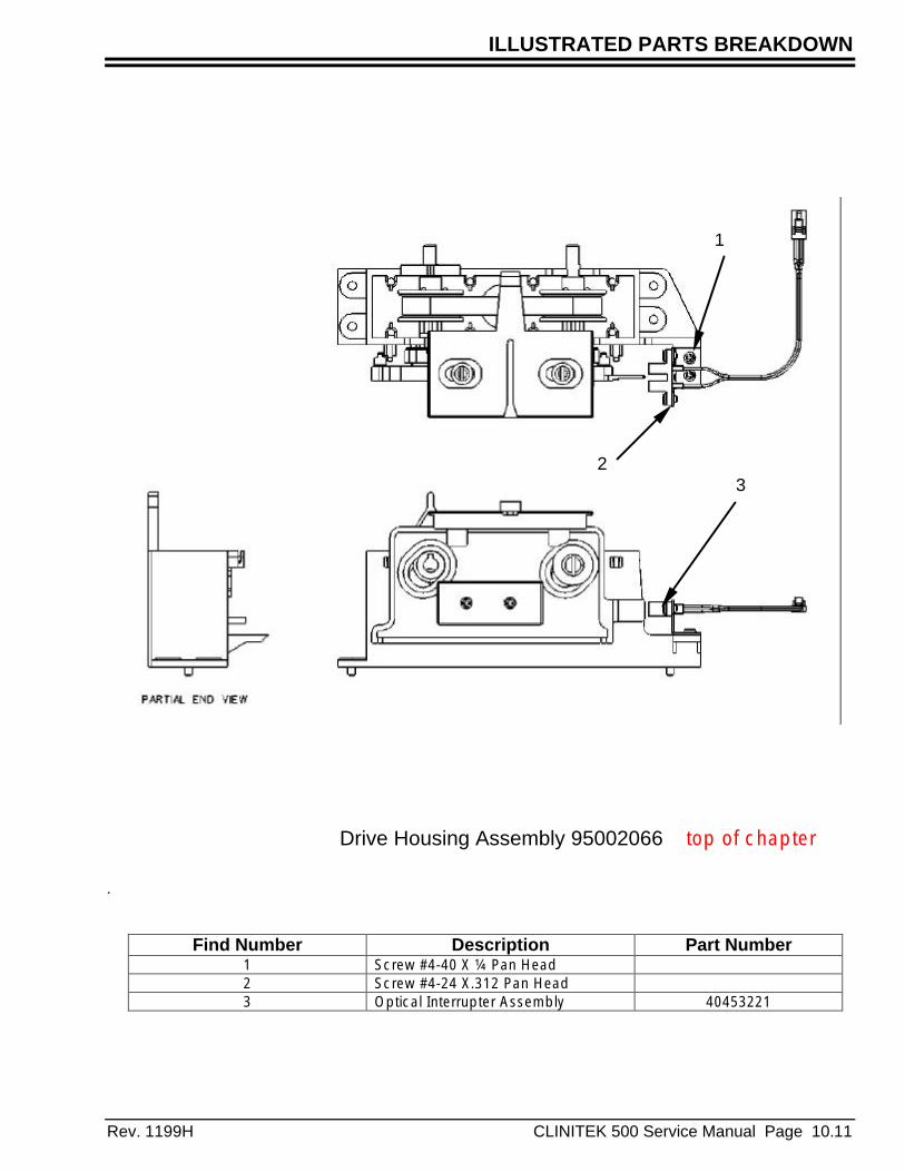
ILLUSTRATED PARTS BREAKDOWN
Rev. 1199H CLINITEK 500 Service Manual Page 10.11
.
1
23
Drive Housing Assembly 95002066 top of chapter
Find Number Description Part Number1 Screw #4-40 X ¼ Pan Head2 Screw #4-24 X.312 Pan Head3 Optical Interrupter Assembly 40453221
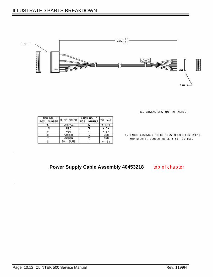
ILLUSTRATED PARTS BREAKDOWN
Page 10.12 CLINTEK 500 Service Manual Rev. 1199H
.
.
.
Power Supply Cable Assembly 40453218 top of chapter

ILLUSTRATED PARTS BREAKDOWN
Rev. 1199H CLINITEK 500 Service Manual Page 10.13
.
Cable Assembly Printer Power 40453219 top of chapter
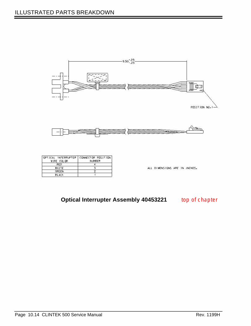
ILLUSTRATED PARTS BREAKDOWN
Page 10.14 CLINTEK 500 Service Manual Rev. 1199H
Optical Interrupter Assembly 40453221 top of chapter
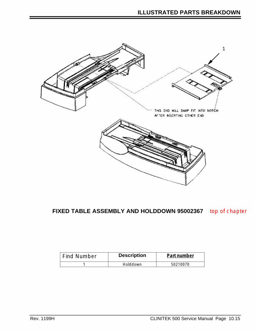
ILLUSTRATED PARTS BREAKDOWN
Rev. 1199H CLINITEK 500 Service Manual Page 10.15
Find Number Description Part number
1 Holddown 50210070
1
FIXED TABLE ASSEMBLY AND HOLDDOWN 95002367 top of chapter

ILLUSTRATED PARTS BREAKDOWN
Page 10.16 CLINTEK 500 Service Manual Rev. 1199H
Bar Code Reader Cable 40453237 top of chapter

ILLUSTRATED PARTS BREAKDOWN
Rev. 1199H CLINITEK 500 Service Manual Page 10.17
Find Number Description Part number 1 Motor Assembly – Readhead 404532052 Motor – Table Drive 404532073 Motor – Pusher Arm 404532064 Bracket – Readhead
Mounting5 Screw M3 x10 Phillips
Cheese Head6 Screw M3 x 12 Phillips
Cheese Head7 Screw 8 x32 x ¾” Pan
Head top of chapter
1
1
2
3
4
65
7
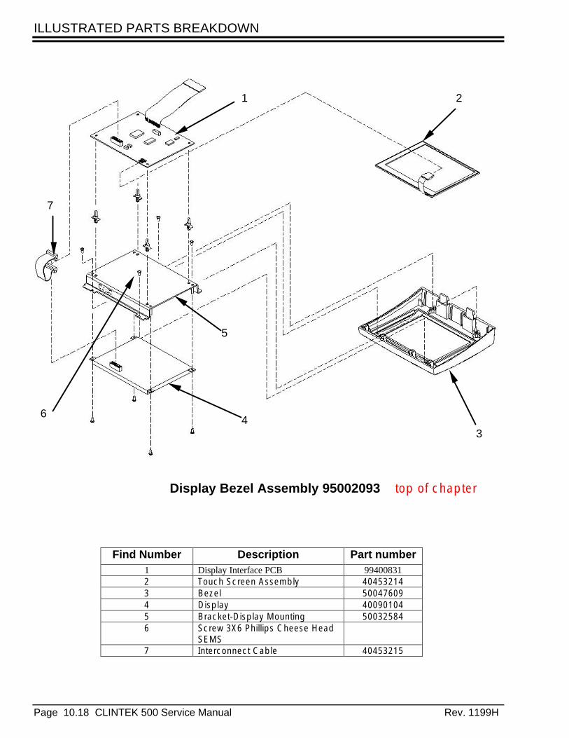
ILLUSTRATED PARTS BREAKDOWN
Page 10.18 CLINTEK 500 Service Manual Rev. 1199H
1 2
34
5
6
7
Find Number Description Part number1 Display Interface PCB 994008312 Touch Screen Assembly 404532143 Bezel 500476094 Display 400901045 Bracket-Display Mounting 500325846 Screw 3X6 Phillips Cheese Head
SEMS7 Interconnect Cable 40453215
Display Bezel Assembly 95002093 top of chapter
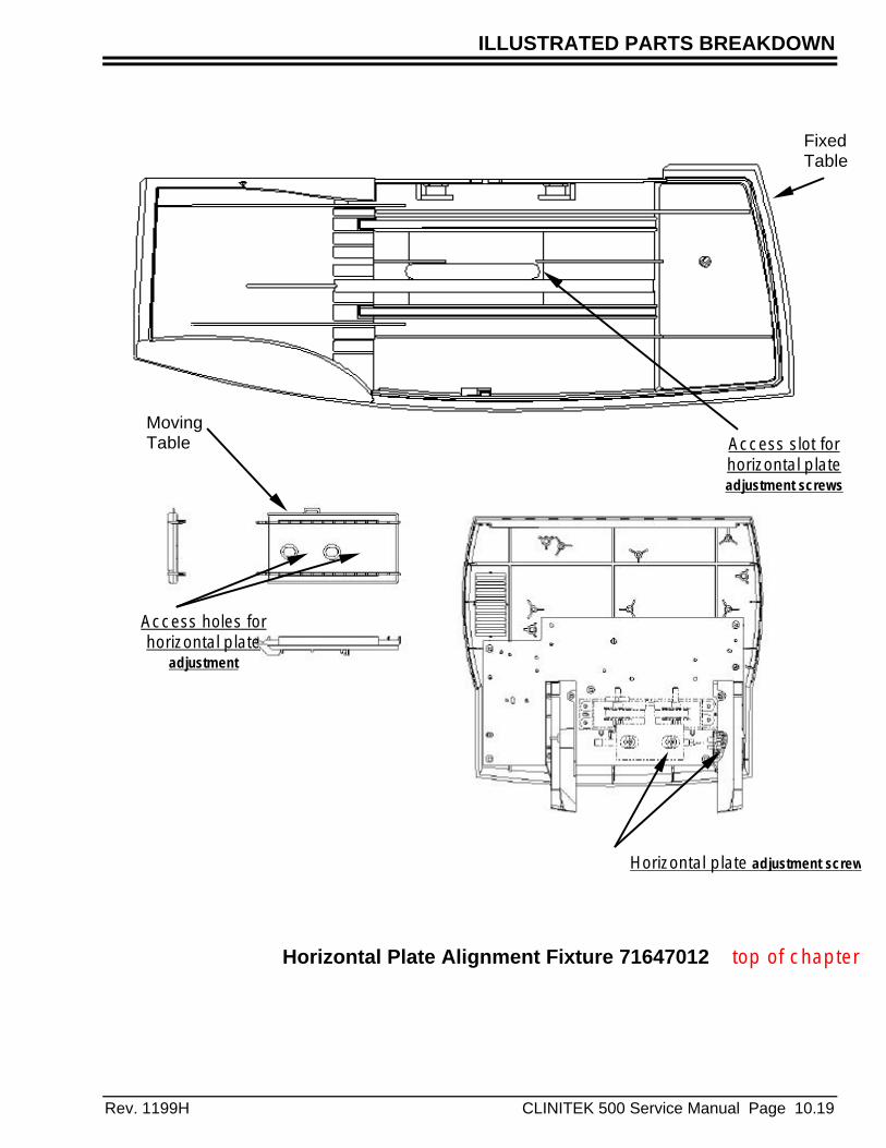
ILLUSTRATED PARTS BREAKDOWN
Rev. 1199H CLINITEK 500 Service Manual Page 10.19
Horizontal plate adjustment screws
Access slot forhorizontal plateadjustment screws
Access holes forhorizontal plate
adjustment
FixedTable
MovingTable
Horizontal Plate Alignment Fixture 71647012 top of chapter

ILLUSTRATED PARTS BREAKDOWN
Page 10.20 CLINTEK 500 Service Manual Rev. 1199H
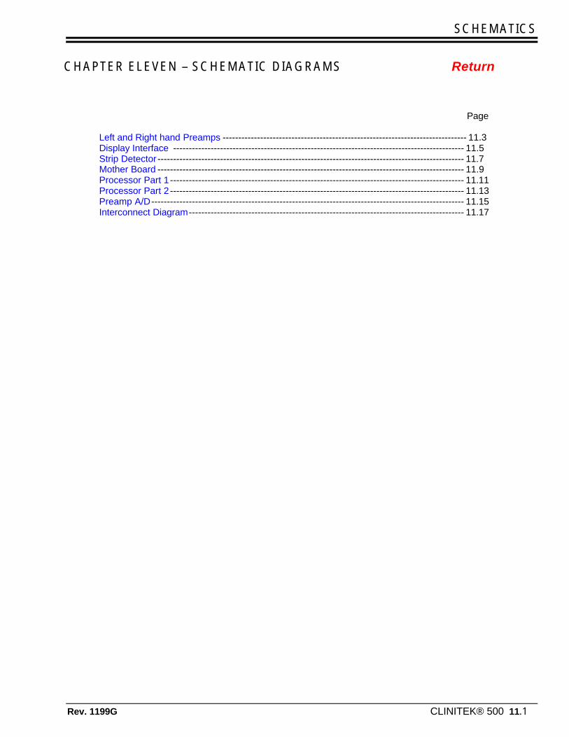
SCHEMATICS
Rev. 1199G CLINITEK® 500 11.1
Chapter 7.
CHAPTER ELEVEN – SCHEMATIC DIAGRAMS Return
Page
Left and Right hand Preamps ------------------------------------------------------------------------------ 11.3Display Interface --------------------------------------------------------------------------------------------- 11.5Strip Detector -------------------------------------------------------------------------------------------------- 11.7Mother Board -------------------------------------------------------------------------------------------------- 11.9Processor Part 1 ---------------------------------------------------------------------------------------------- 11.11Processor Part 2 ---------------------------------------------------------------------------------------------- 11.13Preamp A/D---------------------------------------------------------------------------------------------------- 11.15Interconnect Diagram---------------------------------------------------------------------------------------- 11.17

SCHEMATICS
Rev. 1199G CLINITEK® 500 11.2
TTThhhiiisss pppaaagggeee iiisss iiinnnttteeennntttiiiooonnnaaallllllyyy bbblllaaannnkkk
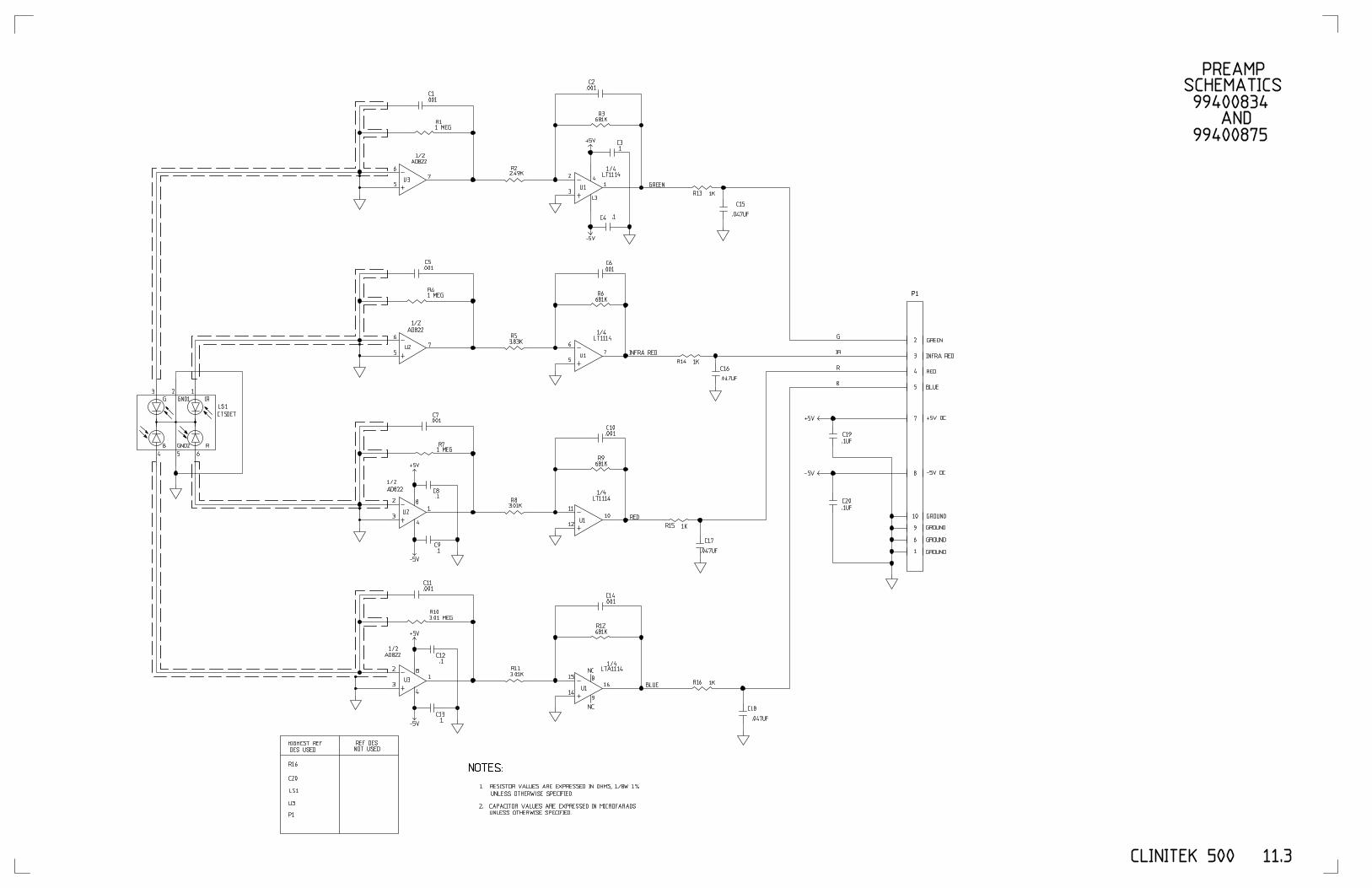

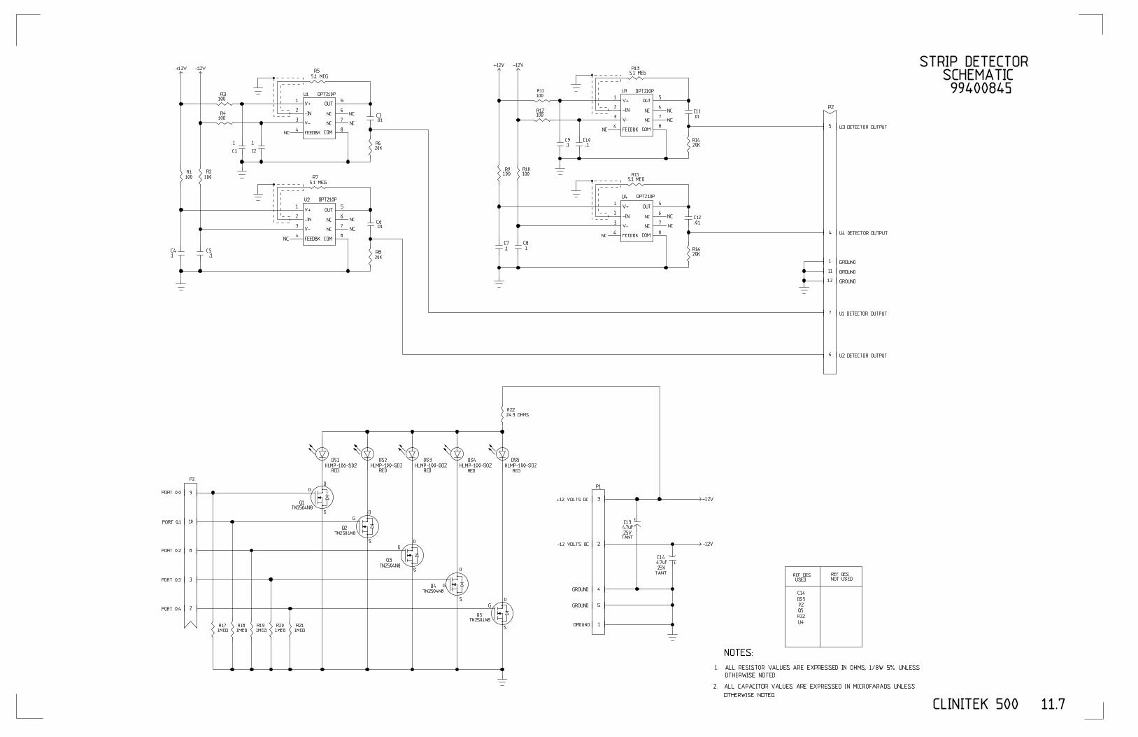
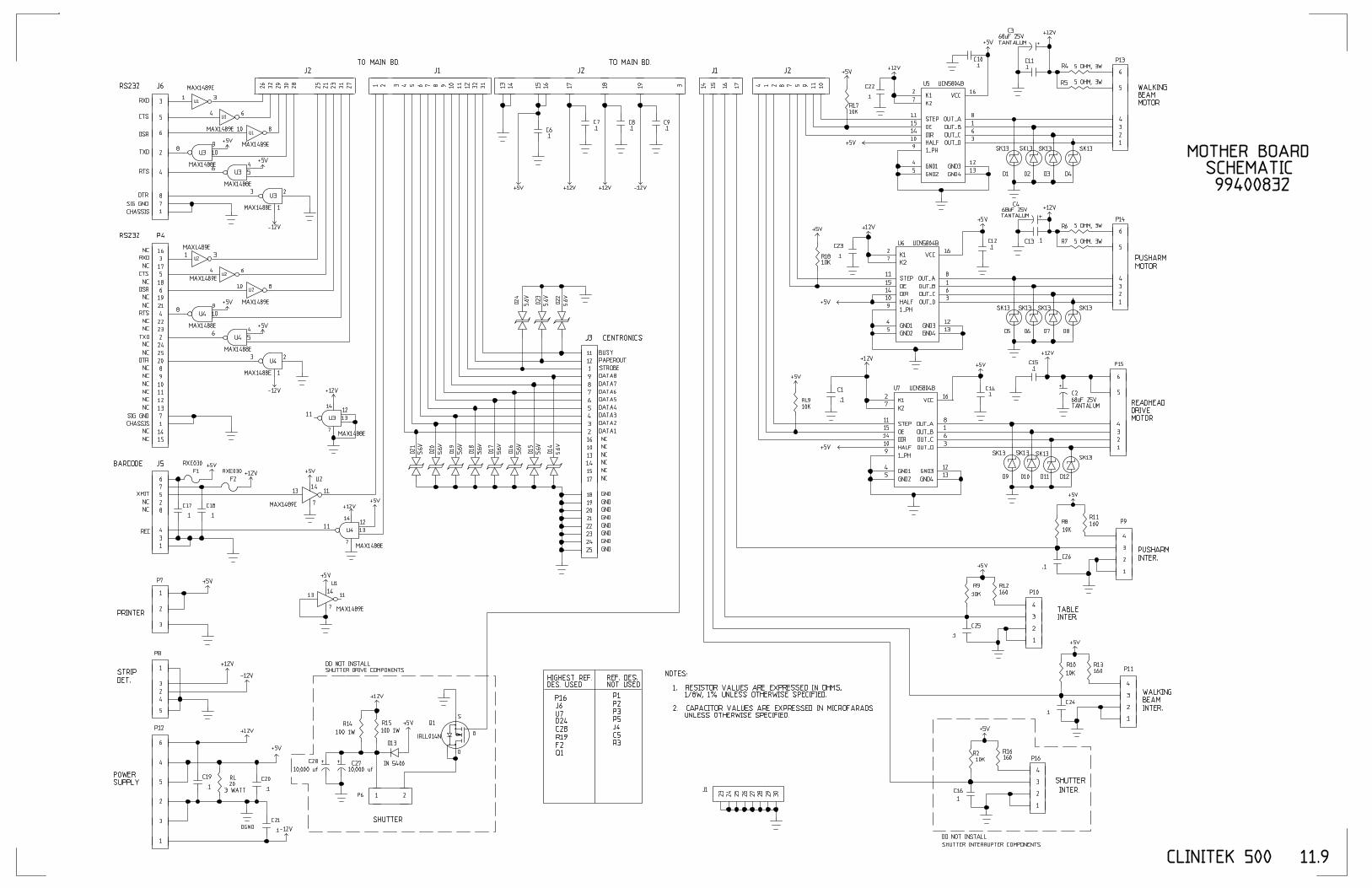


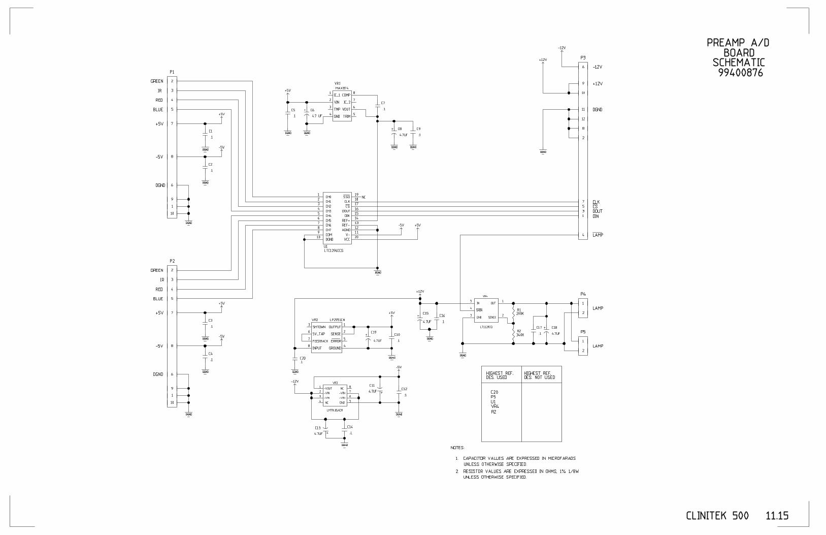

RELEASE TESTING RELEASE TESTING
Rev. 1199H CLINITEK 500 Service Manual Page 12.1
CHAPTER TWELVE – RELEASE TESTING Return
12-0 IntroductionThis section describes cleaning andrelease test procedures that must beperformed prior to releasing anyCLINITEK 500 instrument back to acustomer or into a branch’s CustomerService instrument exchange pool. Theseprocedures must be followed for allsystems processed by Bayer DiagnosticsCustomer Service even if no repair wasactually made.
12-1 Cleaning and Inspection
Reference
CLINITEK 500 Operating Manual,Section 5 “CARE OF THEINSTRUMENT” for cleaninginstructions. top of chapter
CAUTION
Prior to release of any system,carefully inspect to insure that;cables are routed properly,connectors are secure, no missingor loose screws and that there areno sharp edges on the outer case.Inspect the system for cleanlinessand/or cosmetic defects andreplace or clean systemcomponents as necessary.Particular attention should be paidto components which may havebecome stained as a result ofrepeated contact with reagent (i.e.strip sweep or fixed tableassembly).
SectionIntroduction----------------------------------------------------------------------------------------------------- 12-0Cleaning and Inspection ----------------------------------------------------------------------------------- 12-1Exercise All Motions ----------------------------------------------------------------------------------------- 12-2Test Serial Ports
Computer Port----------------------------------------------------------------------------------------- 12-3-1Bar Code Reader Port------------------------------------------------------------------------------- 12-3-2Auxiliary Port------------------------------------------------------------------------------------------- 12-3-3
PrinterInstrument Printer ------------------------------------------------------------------------------------ 12-4-1External Printer---------------------------------------------------------------------------------------- 12-4-2Printer Interface Dip Switch Settings------------------------------------------------------------- 12-4-3
Test Touch Screen ------------------------------------------------------------------------------------------- 12-5Test Display---------------------------------------------------------------------------------------------------- 12-6Cycle Readheads--------------------------------------------------------------------------------------------- 12-7Test Strip Detector ------------------------------------------------------------------------------------------ 12-8Cycle Table ---------------------------------------------------------------------------------------------------- 12-9Cycle Blotter --------------------------------------------------------------------------------------------------- 12-10Setup Strip Centering---------------------------------------------------------------------------------------- 12-11Strip Walk Test ------------------------------------------------------------------------------------------------ 12-12Lubrication------------------------------------------------------------------------------------------------------ 12-13Instrument Release Test------------------------------------------------------------------------------------ 12-14Leukocyte Correction Factor------------------------------------------------------------------------------- 12-15Memory Reset ------------------------------------------------------------------------------------------------- 12-16Confirm Configuration --------------------------------------------------------------------------------------- 12-17

RELEASE TESTING
Page 12.2 CLINITEK 500 Service Manual Rev. 1199H
12-2 Exercise All MotionsReference section 7-3-3-2.
Procedure1. With the instrument power turned OFF,
insert the Instrument PCMCIA Card.
2. Turn the instrument power ON and allowthe system to start normally.
3. From the Main Menu, select“INSTRUMENT TEST”. This will advanceyou to “Instrument Tests, Level 1” menu.
4. Select “EXERCISE ALL MOTIONS” fromthe menu.
5. Select “10 CYCLES”.
6. If all 10 cycles do not pass, an errormessage will appear. top of chapter
12-3 Test Serial PortsReference section 7-3-4-1.
12-3-1 Computer Port
Test Equipment required:
• Computer Port Loop Back Connector(p/n 71500555)
Procedure1. If not already in this condition, with the
instrument power turned OFF, Insert theInstrument Test PCMCIA Card. Turn theinstrument power ON and allow thesystem to start normally.
2. From the Main Menu, select“INSTRUMENT TEST”. This will advanceyou to “Instrument Tests, Level 1” menu.
3. From the “Instrument Tests, Level 1”menu, select “LEVEL 2 TESTS”. This willadvance you to “Instrument Tests, Level2” menu.
4. From the “Instrument Tests, Level 2” menu, select“TEST SERIAL PORTS”.
5. Install Loop-back connector on the serial post.
6. Select “COMPUTER PORT”.
7. Will indicate PASSED if working properly.
12-3-2 Bar Code Reader PortTest Equipment required:• Bar Code Reader Loop Back Connector (p/n
71647007)
Procedure1. If not already in this condition, with the instrument
power turned OFF, Insert the Instrument TestPCMCIA Card. Turn the instrument power ONand allow the system to start normally.
2. From the Main Menu, select “INSTRUMENTTEST”. This will advance you to “InstrumentTests, Level 1” menu.
3. From the “Instrument Tests, Level 1” menu, select“LEVEL 2 TESTS”. This will advance you to“Instrument Tests, Level 2” menu.
4. From the “Instrument Tests, Level 2” menu, select“TEST SERIAL PORTS”.
5. Install Loop-back connector.
6. Select “BAR CODE READER PORT”.
7. Will indicate PASSED if working properly. top of chapter
RELEASE TESTING RELEASE TESTING
Rev. 1199H CLINITEK 500 Service Manual Page 12.3
12-3-3 Auxiliary Port
Test Equipment required:• Auxiliary Loop Back Connector
(p/n 71647006)
Procedure1. If not already in this condition, with the
instrument power turned OFF, Insert theInstrument Test PCMCIA Card. Turn theinstrument power ON and allow thesystem to start normally.
2. From the Main Menu, select“INSTRUMENT TEST”. This will advanceyou to “Instrument Tests, Level 1” menu.
3. From the “Instrument Tests, Level 1”menu, select “LEVEL 2 TESTS”. This willadvance you to “Instrument Tests, Level2” menu.
4. From the “Instrument Tests, Level 2”menu, select “TEST SERIAL PORTS”.
5. Install Loop-back connector.
6. Select “AUXILIARY PORT”.
7. The instrument will indicate PASSED ifworking properly. top of chapter
12-4 Printer
Reference section 7-3-4-2.
12-4-1 Instrument Printer
Procedure
1. If not already in this condition, with theinstrument power turned OFF, Insert theInstrument Test PCMCIA Card. Turn theinstrument power ON and allow thesystem to start normally.
2. From the Main Menu, select “INSTRUMENTTEST”. This will advance you to “InstrumentTests, Level 1” menu.
3. From the “Instrument Tests, Level 1” menu, select“LEVEL 2 TESTS”. This will advance you to“Instrument Tests, Level 2” menu.
4. From the “Instrument Tests, Level 2” menu, select“TEST PRINTERS”.
5. From the “TEST PRINTERS” menu, select“INSTRUMENT PRINTER TEST”.
6. The following pattern should print:
(0123456789)
7. CAPS small letters. st
12-4-2 External Printer
Test Equipment required:• Printer with parallel interface
Procedure1. If not already in this condition, with the instrument
power turned OFF, Insert the Instrument TestPCMCIA Card. Turn the instrument power ONand allow the system to start normally.
2. From the Main Menu, select “INSTRUMENTTEST”. This will advance you to “InstrumentTests, Level 1” menu.
3. From the “Instrument Tests, Level 1” menu, select“LEVEL 2 TESTS”. This will advance you to“Instrument Tests, Level 2” menu.
4. From the “Instrument Tests, Level 2” menu, select“TEST PRINTERS”.
5. Connect a printer to the parallel port.
6. From the “TEST PRINTERS” menu, select“EXTERNAL PRINTER TEST”.
7. The following pattern should print:
(0123456789) CAPITAL LETTERS, small letters.

RELEASE TESTING
Page 12.4 CLINITEK 500 Service Manual Rev. 1199H
12-4-3 Printer Interface PCBDip Switch Settings
The diagrams bellow indicate Dip switch settingfor each switch position
SW1
SW2
SW3
NOTE
When the PCB is installed on theelectronics bracket the “ON” position ofthe DIP switches is in the “Down”position. The switch settings are asfollows.
1=On, 0=Off
Switch position 1 2 3 4 5 6 7 8
SW1 1 1 1 1 0 0 1 1
SW2 0 0 0 0 0 0 0 0
SW3 1 1 1 0
12-5 Test Touch ScreenReference section 7-3-4-3.
Procedure1. If not already in this condition, with the
instrument power turned OFF, Insert theInstrument Test PCMCIA Card. Turn theinstrument power ON and allow thesystem to start normally.
2. From the Main Menu, select “INSTRUMENTTEST”. This will advance you to “InstrumentTests, Level 1” menu.
3. From the “Instrument Tests, Level 1” menu, select“LEVEL 2 TESTS”. This will advance you to“Instrument Tests, Level 2” menu.
4. From the “Instrument Tests, Level 2” menu select“TEST TOUCH SCREEN”.
5. Using your finger, push anyplace on the display.An “x” should appear directly under your finger.
6. To exit, push the arrow in the upper right corner.It will step you back to the Main Menu. top of chapter
12-6 Test DisplayReference section 7-3-4-5.
Procedure1. If not already in this condition, with the instrument
power turned OFF, Insert the Instrument TestPCMCIA Card. Turn the instrument power ONand allow the system to start normally.
2. From the Main Menu, select “INSTRUMENTTEST”. This will advance you to “InstrumentTests, Level 1” menu.
3. From the “Instrument Tests, Level 1” menu, select“LEVEL 2 TESTS”. This will advance you to“Instrument Tests, Level 2” menu.
4. From the “Instrument Tests, Level 2” menu, select“TEST DISPLAY”.
5. All pixels must be highlighted.
6. To exit, push the arrow in the upper right corner.It will step you back to the Main Menu. top of chapter
êêééêêêêonoff
éêêêonoff
ééééééééoffon
8 1
8
14

RELEASE TESTING RELEASE TESTING
Rev. 1199H CLINITEK 500 Service Manual Page 12.5
12-7 Cycle ReadheadsReference section 7-3-6-1.
Procedure1. If not already in this condition, with the
instrument power turned OFF, Insert theInstrument Test PCMCIA Card. Turn theinstrument power ON and allow thesystem to start normally
2. From the Main Menu, select“INSTRUMENT TEST”. This will advanceyou to “Instrument Tests, Level 1” menu.
3. From the “Instrument Tests, Level 1”menu, select “LEVEL 2 TESTS”. This willadvance you to “Instrument Tests, Level2” menu.
4. From the “Instrument Tests, Level 2”menu, select “LEVEL 3 TESTS”. This willadvance you to “Instrument Tests, Level3” menu.
5. From the “Instrument Tests, Level 3”menu, select “LEVEL 4 TESTS”. This willadvance you to “Instrument Tests, Level4” menu.
6. Select “CYCLE READHEADS” from the“Instrument Tests, Level 4” menu.
7. If an error code is not displayed the testpassed.
8. To exit, push the arrow in the upper rightcorner. It will step you back to the MainMenu. top of chapter
12-8 Strip Detector TestReference section 7-3-4-4.
Test Equipment required:• Multistix10 SG Reagent Strips
Procedure1. Select Test Strip Detector function from
Level 2 menu.
2. Place a strip (Multistix10 SG ReagentStrip) on the fixed table. When theinstrument detects a strip it outputs a‘beep’.
3. Move the strip over the Fixed Table covering allthe valid strip placement positions. These arebetween the Pusher Bar and the hood of theupper case which covers the readheads. Keepthe end of the strip (last pad) inside the rear ribon the platform.
4. Visually verify that 4 LED’s are flashing.
Note
On early units, a 5th LED on the far left may bepresent but disabled.
5. Press Print Detector Setup Values. Inspect theprintout and confirm that the values are between‘10’ and ‘254’.
6. If ‘0’ or ‘255’are reported, then a failure should berecorded and the system needs to be rejectedand returned for troubleshooting. top of chapter
12-9 Cycle TableReference section 7-3-6-2.
Procedure1. If not already in this condition, with the instrument
power turned OFF, Insert the Instrument TestPCMCIA Card. Turn the instrument power ONand allow the system to start normally.
2. From the Main Menu, select “INSTRUMENTTEST”. This will advance you to “InstrumentTests, Level 1” menu.
3. From the “Instrument Tests, Level 1” menu, select“LEVEL 2 TESTS”. This will advance you to“Instrument Tests, Level 2” menu.
4. From the “Instrument Tests, Level 2” menu, select“LEVEL 3 TESTS”. This will advance you to“Instrument Tests, Level 3” menu.
RELEASE TESTING
Page 12.6 CLINITEK 500 Service Manual Rev. 1199H
5. From the “Instrument Tests, Level 3”menu, select “LEVEL 4 TESTS”. This willadvance you to “Instrument Tests, Level4” menu.
6. Select “CYCLE TABLE” from the“Instrument Tests, Level 4” menu.
7. If an error code is not displayed, the testpassed.
8. To exit, push the arrow in the upper rightcorner. It will step you back to the MainMenu. top of chapter
12-10 Cycle BlotterReference section 7-3-6-3.
Procedure1. If not already in this condition, with the
instrument power turned OFF, Insert theInstrument Test PCMCIA Card. Turn theinstrument power ON and allow thesystem to start normally.
2. From the Main Menu, select“INSTRUMENT TEST”. This will advanceyou to “Instrument Tests, Level 1” menu.
3. From the “Instrument Tests, Level 1”menu, select “LEVEL 2 TESTS”. This willadvance you to “Instrument Tests, Level2” menu.
4. From the “Instrument Tests, Level 2”menu, select “LEVEL 3 TESTS”. This willadvance you to “Instrument Tests, Level3” menu.
5. From the “Instrument Tests, Level 3”menu, select “LEVEL 4 TESTS”. This willadvance you to “Instrument Tests, Level4” menu.
6. Select “CYCLE BLOTTER” from the“Instrument Tests, Level 4” menu.
7. If an error codes is not displayed the testpassed.
8. To exit, push the arrow in the upper rightcorner. It will step you back to the MainMenu. top of chapter
12-11 Setup Strip CenteringEquipment required:
• Floating Table Hold-down(p/n 71647013)
• Hard Standard Strip(p/n 95002262)Referance section 7-3-3-4
Procedure
1. Install the “Floating Rail Hold-down onto the Fixedtable and install the Fixed table onto theinstrument.
2. Insert the Instrument Test Card. If not already inthis condition, with the instrument power turnedOFF, Insert the Instrument Test Card. Turn theinstrument power ON and allow the system tostart normally.
3. From the Main Menu, select “INSTRUMENTTEST”. This will advance you to “InstrumentTests, Level 1” menu.
4. Select the “SETUP STRIP CENTERING” test. Thescreen will display the current “Strip Centering”value stored in the instrument memory.
5. Place the Hard Standard strip onto the load zoneof the fixed table and select the “OK” key. Theinstrument will then advance the strip under thereadheads and calculate a new “Strip Centering “value and store it in the instrument memory. Theacceptable range is 4 to 40. top of chapter
12-12 Strip Walk TestReference section 7-3-3-6.
Procedure1. Insert the Instrument PCMCIA Card. If not already
in this condition, with the instrument power turnedOFF, Insert the Instrument Test PCMCIA Card.Turn the instrument power ON and allow thesystem to start normally.

RELEASE TESTING RELEASE TESTING
Rev. 1199H CLINITEK 500 Service Manual Page 12.7
2. From the Main Menu, select“INSTRUMENT TEST”. This will advanceyou to “Instrument Tests, Level 1” menu.
3. Select “STRIP WALK TEST” from the“Instrument Tests, Level 1” menu.
4. The instrument prompts the user toprepare to load 10 strips on to the loadzone of the fixed table.
5. Once the “O.K.” key is pressed, theinstrument starts the test, as each strip isplaced on the load zone of the fixed tablethe pusher arm is activated and movesthe strip to the moving table.
6. As the strips are moved under eachreadhead, the strip tip is located andstored in memory. After all ten strips havehad the tip locations checked by bothreadheads the data is analyzed.
7. A print out of the data and test results isprinted out on the internal printer (seefigure 7-3-1). Refer to section 7-3-3-6 todetermine if the instrument passes thetest. top of chapter
In case of a system failing this test, the DriveHousing assembly will require replacement.
12-13 Lubrication
Procedure1. Clean the Pusher Bar Slide Arm Shaft with
alcohol.
2. Apply a thin coat of Lubriplate 630-AAMulti-purpose Grease, part number50336008.
12-14 Instrument Release Test
Reference Section 7-3-3-1.
Material Required:• 40453255 DB25 to DB9 Null Modem Cable• SR00169X Release Test Software• SR00170X Release Test Limits• SR00081X Instrument Test PCMCIA Card• 95002262 Hard Stardard Test Strip• IBM-PC Compatible computer. Minimum
Configuration of 486, 33MHz, 8 Meg Memoryrunning Microsoft Windows 3.1 or MicrosoftWindows 95
• Referance Appendix A for software installation andoperation.
• Refer to the recommended spare part list (RSL)024E6470 for current part numbers and fixtures
The Instrument Release Test uses a special test strip(part number 95002262) and a PC running the Releasetest software (part number SR001690 and SR001700) toperform a Quality check on the operation of theinstrument. In this test data is output from theinstrument and collected by the PC running the releasesoftware. Next, the data is analyzed and compared topredefined limits and if, the results are within the limits,the instrument passes the test. A pass or fail will bedisplayed on the PC screen
The Test strip that is used for the release test has padsin the following positions P4, P9, P10 and P11.
Procedure1. With the power off, connect the CT 500 serial to
the serial from the PC. Install the floating railHolddown on the Fixed and install the assemblyon the instrument.
2. Power the CLINITEK 500 instrument ON andselect the Release Test from the menu.

RELEASE TESTING
Page 12.8 CLINITEK 500 Service Manual Rev. 1199H
3. Place the test strip onto the reagent loadarea of the fixed table and push "OK"button.
4. The instrument moves the strip to the firstreadhead and scans the strip 10 times,doing the normal positioning, calibration,and readhead movement. Only thereflectance results are saved for output.
5. Calibration is then performed on the firstcalibration chip. During the calibration,the reflectances, light counts, and darkcounts are stored.
6. The results from the first readhead arestored as sequence number 001.
7. The strip is then quickly moved secondreadhead and steps 3 and 4 are repeatedand stored as sequence number 002.
8. The results are available after the strip isread at the second readhead and will beoutput when asked for by a connectedcomputer.
9. The computer screen will display if theinstrument pass or fails the test. If it fails,refer to appendix A for details. (Note: It ispossible for the test to be failed due to aprogram version number mismatch. In thiscase review the detail screen and confirmthat all other tests pass, back lit in green,and continue the Release testing)
10. If the test is repeated, any results from aprevious test are overwritten.
11. The results may also be printed. top of chapter
12-15 Leukocyte Correction FactorGeneration
Equipment Required• Instrument Test Card (version 1.03 / 1.03 or
higher)
• CT500 Calibration Solution (95002503)
• Multistix 10 SG reagent strips (10 strips requiredfor test)
• Urinetek tubes of equivalent
• Test Tube Holder (opitional)
• Paper Towel
Procedure
1. With the Instrument OFF insert the Instrument TestCard in to the system.
2. Turn the instrument power ON.
3. Scroll through the menu options until you reachthe “Instrument Tests, Level 4” menu (see below).Select the “Generate LEU Corr Factor menuoption.
Instrument Tests, Level 4
CYCLE READHEADS
CYCLE TABLE
CYCLE PUSH BAR
READ STRIP, DUMP DATA
PRINT TRANSFERRED DATA
GENERATE LEU CORR. FACTOR

RELEASE TESTING RELEASE TESTING
Rev. 1199H CLINITEK 500 Service Manual Page 12.9
4. The first screen displayed in the LeuCorrection Factor test is shown below.
The variable “AA” indicates the current LEUcorrection factor stored for the instrument. Thecorrection factor can have value from –99 to+99.
If the Instrument has not previously had a Leucorrection Factor generated, the value of “AA”=00 and no sign (+ / -) will be shown.
5. To set a new correction factor press thekey “Generate LEU Corr. Factor”, whichwill then display the following screen.
6. When the above screen is displayed, theinstrument is ready to start having stripsplaced upon the load zone of theinstrument.
Dipping Strips
The bottle of reagent strips must be stored at roomtemperature (20-30oC/66-86oF) for at least 1 daybefore the normalization procedure is performed.All strips for a given instrument must come from thesame bottle.Remove 10 strips from the bottle just prior to dippingand re-cap the bottle.Fill a suitable tube with enough test (approximately 10ml) solution to allow all 10 of the reagent pads to besubmerged when the strip is dipped.The test solution can be used for dipping 1o strips,and then fresh solution will be needed.
LEU CORRECTION FACTOR: AA
GENERATE LEU CORR. FACTOR
Use: MULTISTIX 10 SG RUN 10 STRIPS FOR NEW CORRECTION
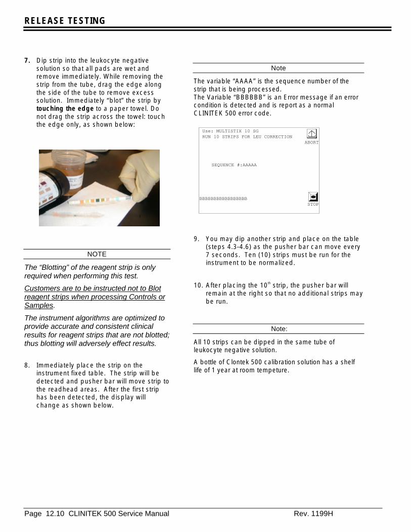
RELEASE TESTING
Page 12.10 CLINITEK 500 Service Manual Rev. 1199H
7. Dip strip into the leukocyte negativesolution so that all pads are wet andremove immediately. While removing thestrip from the tube, drag the edge alongthe side of the tube to remove excesssolution. Immediately “blot” the strip bytouching the edge to a paper towel. Donot drag the strip across the towel: touchthe edge only, as shown below:
NOTE
The “Blotting” of the reagent strip is onlyrequired when performing this test.
Customers are to be instructed not to Blotreagent strips when processing Controls orSamples.
The instrument algorithms are optimized toprovide accurate and consistent clinicalresults for reagent strips that are not blotted;thus blotting will adversely effect results.
8. Immediately place the strip on theinstrument fixed table. The strip will bedetected and pusher bar will move strip tothe readhead areas. After the first striphas been detected, the display willchange as shown below.
Note
The variable “AAAA” is the sequence number of thestrip that is being processed.The Variable “BBBBBB” is an Error message if an errorcondition is detected and is report as a normalCLINITEK 500 error code.
9. You may dip another strip and place on the table(steps 4.3-4.6) as the pusher bar can move every7 seconds. Ten (10) strips must be run for theinstrument to be normalized.
10. After placing the 10th strip, the pusher bar willremain at the right so that no additional strips maybe run.
Note:
All 10 strips can be dipped in the same tube ofleukocyte negative solution.
A bottle of Clontek 500 calibration solution has a shelflife of 1 year at room tempeture.
Use: MULTISTIX 10 SG RUN 10 STRIPS FOR LEU CORRECTION
ABORT
SEQUENCE #:AAAAA
BBBBBBBBBBBBBBBBBSTOP

RELEASE TESTING RELEASE TESTING
Rev. 1199H CLINITEK 500 Service Manual Page 12.11
11. Once all ten strips have been processed,the results are displayed on the screen asshown above. A printout of the data setsand the minimum, maximum, range, andaverage decode results will automaticallybe printed after CT500 normalization iscomplete.
12. An instrument passes the test providedthat the range value for the test is lessthan or equal to 34.
Note
Instruments that do not pass this requirementshould be retested. If the instrument fails asecond testing, it requires additionalservicing. top of chapter
LEU Correction Factor
AVERAGE: AAA
MAXIMUM: BBB
MINIMUM: CCC
RANGE: DD
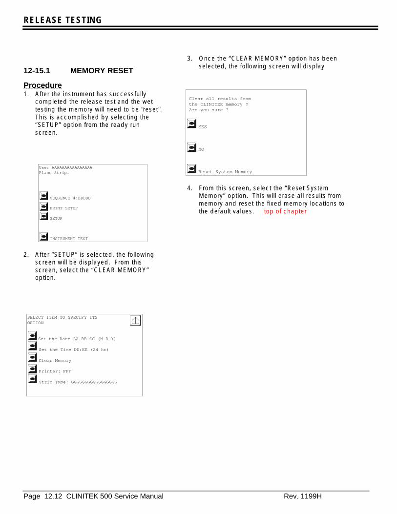
RELEASE TESTING
Page 12.12 CLINITEK 500 Service Manual Rev. 1199H
12-15.1 MEMORY RESET
Procedure1. After the instrument has successfully
completed the release test and the wettesting the memory will need to be "reset".This is accomplished by selecting the“SETUP” option from the ready runscreen.
2. After “SETUP” is selected, the followingscreen will be displayed. From thisscreen, select the “CLEAR MEMORY”option.
3. Once the “CLEAR MEMORY” option has beenselected, the following screen will display
4. From this screen, select the “Reset SystemMemory” option. This will erase all results frommemory and reset the fixed memory locations tothe default values. top of chapter
Use: AAAAAAAAAAAAAAAAPlace Strip.
SEQUENCE #:BBBBB
PRINT SETUP
SETUP
INSTRUMENT TEST
SELECT ITEM TO SPECIFY ITSOPTION
Set the Date AA-BB-CC (M-D-Y)
Set the Time DD:EE (24 hr)
Clear Memory
Printer: FFF
Strip Type: GGGGGGGGGGGGGGGGG
Clear all results from the CLINITEK memory ? Are you sure ?
YES
NO
Reset System Memory
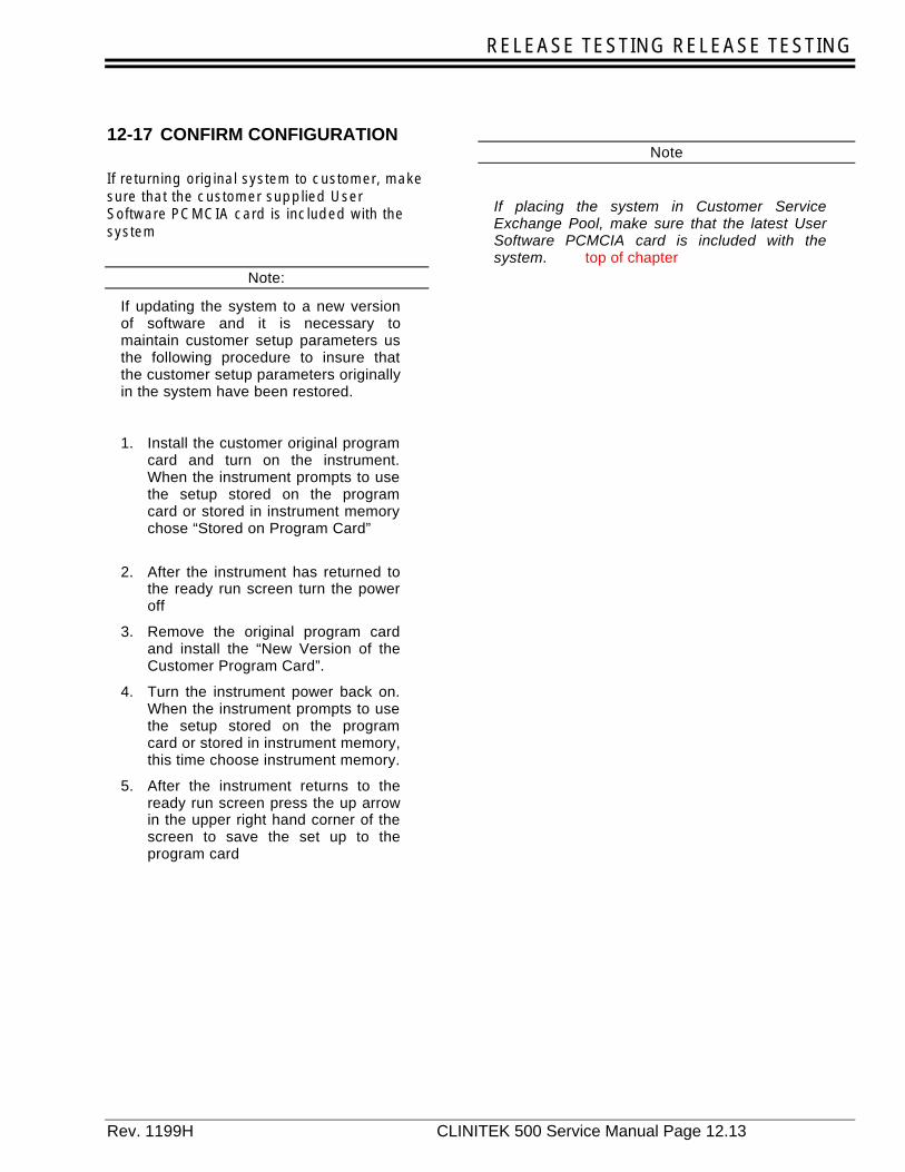
RELEASE TESTING RELEASE TESTING
Rev. 1199H CLINITEK 500 Service Manual Page 12.13
12-17 CONFIRM CONFIGURATION
If returning original system to customer, makesure that the customer supplied UserSoftware PCMCIA card is included with thesystem
Note:
If updating the system to a new versionof software and it is necessary tomaintain customer setup parameters usthe following procedure to insure thatthe customer setup parameters originallyin the system have been restored.
1. Install the customer original programcard and turn on the instrument.When the instrument prompts to usethe setup stored on the programcard or stored in instrument memorychose “Stored on Program Card”
2. After the instrument has returned tothe ready run screen turn the poweroff
3. Remove the original program cardand install the “New Version of theCustomer Program Card”.
4. Turn the instrument power back on.When the instrument prompts to usethe setup stored on the programcard or stored in instrument memory,this time choose instrument memory.
5. After the instrument returns to theready run screen press the up arrowin the upper right hand corner of thescreen to save the set up to theprogram card
Note
If placing the system in Customer ServiceExchange Pool, make sure that the latest UserSoftware PCMCIA card is included with thesystem. top of chapter

RELEASE TESTING
Page 12.14 CLINITEK 500 Service Manual Rev. 1199H
CLINITEK 500 RELEASE TEST LOG
DATE:_____/_____/_____ S/N:_________________
A. Cosmetic Inspection and Cleaning ------------------------------------------------------------------q
B. Exercise All Motions-------------------------------------------------------------------------------------q
C. Test Serial Ports
1. Computer Port q
2. Bar Code Reader Port ---------------------------------------------------------------------q
3. Auxiliary Port ---------------------------------------------------------------------------------q
D. Printer
1. Instrument Printer ---------------------------------------------------------------------------q
2. External Printer ------------------------------------------------------------------------------q
E. Test Touch Screen ---------------------------------------------------------------------------------------q
F. Test Display ------------------------------------------------------------------------------------------------q
G. Cycle Readheads -----------------------------------------------------------------------------------------q
H. Test Strip Detector----------------------------------------------------------------------------------------q
I. Cycle Table -------------------------------------------------------------------------------------------------q
J. Cycle Blotter------------------------------------------------------------------------------------------------q
K. Set Strip Centering ---------------------------------------------------------------------------------------q
L. Strip Walk Test --------------------------------------------------------------------------------------------q
M. Lubrication --------------------------------------------------------------------------------------------------q
N. Service release Test -------------------------------------------------------------------------------------q
O. LEU Correction Factor=_______ ---------------------------------------------------------------------q
P. Reset Memory ---------------------------------------------------------------------------------------------q
Q. Confirm Software Configuration-----------------------------------------------------------------------q
Software Version __________________
Performed By: ________________________ Date: __________
Release Approval: _____________________ Date: __________

APPENDIX A
Rev. 1199H CLINITEK 500 Service Manual Page A.1
Appendix A-CLINITEK 500 Instrument Release Test Data CollectionSoftware Return
A-0 Introduction This appendix will address installing and using the Data Collection Software with the CLINITEK 500 instrument.
Performing the Release Test requires the use of Instrument Test Card and a special data collection program (p/nSR00169A) that will analyze the data from the CLINITEK 500 instrument. This software is supplied in two parts:First is a CD-ROM, which contains the actual data collection program and a “Set-up” program for installing thesoftware onto a PC. The second part is a floppy disk, which contains the “Limits Files” (p/n SR00170A) that areused to determine if data collected from the CLINITEK 500 instrument under test meets the releaserequirements.
A-1 Software Installation
A-1-1 Hardware Requirements
The following is a listing of Hardware Requirements
PC configured as followsProcessor 486 66Mhz (minimum requirement)RAM Memory: recommend 16 Meg (8 Meg minimum)An available serial portHard Drive with 20 free spaceCD ROM drive3.5 inch Floppy disk drive
Operating system:Windows 3.11 or Windows 95
Null modem serial cable (CLINITEK 500 Service fixture part number 40453255)
A-1-2 Software Installation Guide
A-1-2-1 Windows 3.1 installation
1. Turn the PC on and allow it to run its normal start-up sequence.
2. Insert the CD Disk containing the data collection software into the CD-ROM drive.
3. Select the File and then Select Run from the drop down menu that will appear.
4. From the Run option select Browse and select the drive letter appropriate for the CD-ROM drive.Choose the “Setup.exe” file from the choices displayed and enter O.K.
5. Enter “O.K.” to Run “Setup.exe.” At this point, the software will create a directory self install theprograms.
6. After the program has been installed onto the hard drive the limits files will need to be copied into thesame directory as the program. Once this has been completed, the program will be ready to be used.
APPENDIX A
Page A.2 CLINITEK 500 Service Manual Rev. 1199H
A-1-2-2 Windows 95 installation
1. Turn the PC on and allow it to run its normal start-up sequence.
2. Insert the CD Disk containing the data collection software into the CD-ROM drive.
3. Select the Start box and then Select Run from the drop down menu that will appear.
4. From the Run option select Browse and select the drive letter appropriate for the CD-ROM drive.Choose the “Setup.exe” file from the choices displayed and enter O.K.
5. Enter “O.K.” to Run “Setup.exe”. At this point, the software will create a directory self install theprograms.
6. After the program has been install onto the hard drive the limits files will need to be copied into thesame directory as the program. Once this has been completed, the program will be ready to be used.

APPENDIX A
Rev. 1199H CLINITEK 500 Service Manual Page A.3
7.
A-2 Operation of Software1. In Windows 3.1 double click on the CT500 program icon. For Windows 95, select the Start button and
then Programs. When the program menu slides out click on the CT500 program. This will start theprogram
2. When the program starts a screen will appear requiring the following information to be entered:
Employee ID 000000
Procedure #= 4099
Test Procedure Revision Level=05
3. After the log on codes are entered the following screen will be displayed. To run the program select theRun button
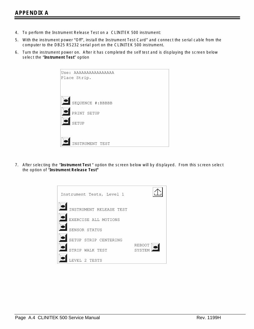
APPENDIX A
Page A.4 CLINITEK 500 Service Manual Rev. 1199H
4. To perform the Instrument Release Test on a CLINITEK 500 instrument:
5. With the instrument power “Off”, install the Instrument Test Card” and connect the serial cable from thecomputer to the DB25 RS232 serial port on the CLINITEK 500 instrument.
6. Turn the instrument power on. After it has completed the self test and is displaying the screen belowselect the “Instrument Test” option
7. After selecting the “Instrument Test “ option the screen below will by displayed. From this screen selectthe option of “Instrument Release Test”
Use: AAAAAAAAAAAAAAAAPlace Strip.
SEQUENCE #:BBBBB
PRINT SETUP
SETUP
INSTRUMENT TEST
Instrument Tests, Level 1
INSTRUMENT RELEASE TEST
EXERCISE ALL MOTIONS
SENSOR STATUS
SETUP STRIP CENTERINGREBOOT
STRIP WALK TEST SYSTEM
LEVEL 2 TESTS

APPENDIX A
Rev. 1199H CLINITEK 500 Service Manual Page A.5
8. The screen below will be displayed on the PC. The model number 6470 followed by the instrumentserial number needs to be entered into the Model Serial Number field (example: 6470-1000310)
9. The screen will change to below if the Product Code and Serial Number are entered correctly

APPENDIX A
Page A.6 CLINITEK 500 Service Manual Rev. 1199H
10. Move the cursor to the “Mode” button and click on it. Make sure that “Raw Data”, ADF” and “TestResults” are all switched to “OFF”. This can be verified by see that the bottom of the screen has theseoptions highlighted in red.
11. Move the cursor to the “test” button. A drop down menu will appear. Select the “Start Session” Option.
12. On the CLINITEK 500 instrument place a hard standards test strip on the fixed table and press thebegin test key.
13. If the computer and the CLINITEK 500 instrument are set up correctly, you will see the “CommunicationsStatus” indicator toggling between “Idle” and “Active”. Additionally the “Hard Standard Results Port 2”will display “Pending” (See screen below). It will take several minutes for the testing to completedepending upon the processor speed of the PC that is running the data collection software.
14. When all of the data has been analyzed the “Hard Standard Results Port 2” will change color fromyellow to green and “Pending” will change to “Pass”. At this point the CLINITEK 500 instrument canhave its power turned off and be disconnected from the PC.
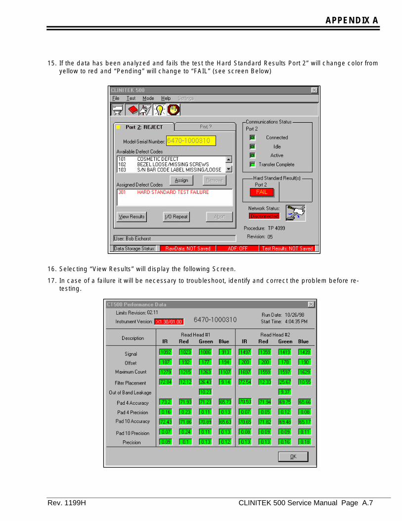
APPENDIX A
Rev. 1199H CLINITEK 500 Service Manual Page A.7
15. If the data has been analyzed and fails the test the Hard Standard Results Port 2” will change color fromyellow to red and “Pending” will change to “FAIL” (see screen Below)
16. Selecting “View Results” will display the following Screen.
17. In case of a failure it will be necessary to troubleshoot, identify and correct the problem before re-testing.
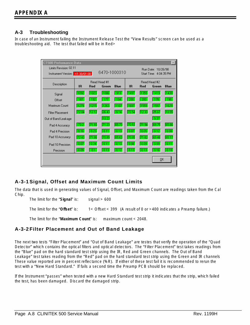
APPENDIX A
Page A.8 CLINITEK 500 Service Manual Rev. 1199H
A-3 TroubleshootingIn case of an Instrument failing the Instrument Release Test the “View Results” screen can be used as atroubleshooting aid. The test that failed will be in Red>
A-3-1 Signal, Offset and Maximum Count Limits
The data that is used in generating values of Signal, Offset, and Maximum Count are readings taken from the CalChip.
The limit for the “Signal” is: signal > 600
The limit for the “Offset” is: 1< Offset < 399 (A result of 0 or >400 indicates a Preamp failure.)
The limit for the “Maximum Count” is: maximum count < 2048.
A-3-2 Filter Placement and Out of Band Leakage
The next two tests “Filter Placement” and “Out of Band Leakage” are testes that verify the operation of the “QuadDetector” which contains the optical filters and optical detectors. The “Filter Placement” test takes readings fromthe “Blue” pad on the hard standard test strip using the IR, Red and Green channels. The Out of BandLeakage” test takes reading from the “Red” pad on the hard standard test strip using the Green and IR channelsThese value reported are in percent reflectance (%R). If either of these test fail it is recommended to rerun thetest with a “New Hard Standard.” If fails a second time the Preamp PCB should be replaced.
If the Instrument “passes” when tested with a new Hard Standard test strip it indicates that the strip, which failedthe test, has been damaged. Discard the damaged strip.
APPENDIX A
Rev. 1199H CLINITEK 500 Service Manual Page A.9
A-3-3 Accuracy Pad 4 and Pad 10
Failure of these tests indicates that the Cal Chip on the Fixed Table is not in the proper position (incorrect heightof angle). Retest the instrument using a different fixed table, if the error remains it could indicate a problem withthe mounting of the table.
A-3-4 Precision Pad 4 and Pad 10
If either of these tests fail, repeat the test a second time with a New Hard Standard test strip. If the error remainsit indicates that the lamp may be dirty (clean with alcohol and air dry) or the A/D PCB is not operating correctly(replace A/D PCB)
APPENDIX A
Page A.10 CLINITEK 500 Service Manual Rev. 1199H
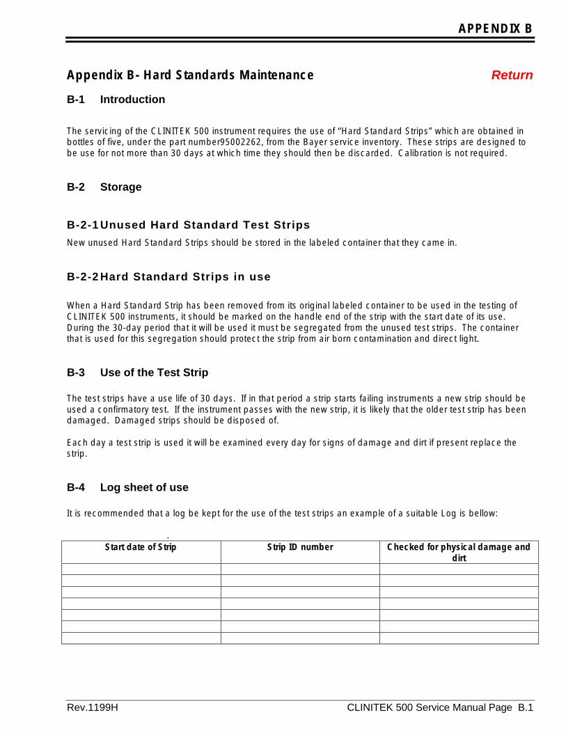
APPENDIX B
Rev.1199H CLINITEK 500 Service Manual Page B.1
Appendix B- Hard Standards Maintenance Return
B-1 Introduction
The servicing of the CLINITEK 500 instrument requires the use of “Hard Standard Strips” which are obtained inbottles of five, under the part number95002262, from the Bayer service inventory. These strips are designed tobe use for not more than 30 days at which time they should then be discarded. Calibration is not required.
B-2 Storage
B-2-1 Unused Hard Standard Test Strips
New unused Hard Standard Strips should be stored in the labeled container that they came in.
B-2-2 Hard Standard Strips in use
When a Hard Standard Strip has been removed from its original labeled container to be used in the testing ofCLINITEK 500 instruments, it should be marked on the handle end of the strip with the start date of its use.During the 30-day period that it will be used it must be segregated from the unused test strips. The containerthat is used for this segregation should protect the strip from air born contamination and direct light.
B-3 Use of the Test Strip
The test strips have a use life of 30 days. If in that period a strip starts failing instruments a new strip should beused a confirmatory test. If the instrument passes with the new strip, it is likely that the older test strip has beendamaged. Damaged strips should be disposed of.
Each day a test strip is used it will be examined every day for signs of damage and dirt if present replace thestrip.
B-4 Log sheet of use
It is recommended that a log be kept for the use of the test strips an example of a suitable Log is bellow:
.Start date of Strip Strip ID number Checked for physical damage and
dirt

APPENDIX B
Page B.2 CLINITEK 500 Service Manual Rev. 1199G
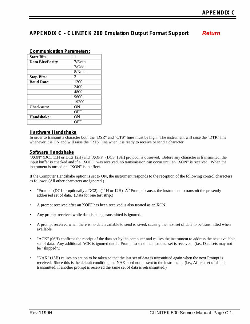
APPENDIX C
Rev.1199H CLINITEK 500 Service Manual Page C.1
APPENDIX C - CLINITEK 200 Emulation Output Format Support Return
Communication Parameters:Start Bits: 1Data Bits/Parity 7/Even
7/Odd8/None
Stop Bits: 2Baud Rate: 1200
24004800960019200
Checksum: ONOFF
Handshake: ONOFF
Hardware HandshakeIn order to transmit a character both the "DSR" and "CTS" lines must be high. The instrument will raise the "DTR" linewhenever it is ON and will raise the "RTS" line when it is ready to receive or send a character.
Software Handshake"XON" (DC1 11H or DC2 12H) and "XOFF" (DC3, 13H) protocol is observed. Before any character is transmitted, theinput buffer is checked and if a "XOFF" was received, no transmission can occur until an "XON" is received. When theinstrument is turned on, "XON" is in effect.
If the Computer Handshake option is set to ON, the instrument responds to the reception of the following control charactersas follows: (All other characters are ignored.)
• "Prompt" (DC1 or optionally a DC2). (11H or 12H) A "Prompt" causes the instrument to transmit the presentlyaddressed set of data. (Data for one test strip.)
• A prompt received after an XOFF has been received is also treated as an XON. • Any prompt received while data is being transmitted is ignored. • A prompt received when there is no data available to send is saved, causing the next set of data to be transmitted when
available. • "ACK" (06H) confirms the receipt of the data set by the computer and causes the instrument to address the next available
set of data. Any additional ACK is ignored until a Prompt to send the next data set is received. (i.e., Data sets may notbe "skipped".)
• "NAK" (15H) causes no action to be taken so that the last set of data is transmitted again when the next Prompt is
received. Since this is the default condition, the NAK need not be sent to the instrument. (i.e., After a set of data istransmitted, if another prompt is received the same set of data is retransmitted.)

APPENDIX C
Page C.2 CLINITEK 500 Service Manual Rev. 1199H
Computer Port Connections (Serial RS-232)Pin # Signal Name Function Signal Source1 chas gnd protective ground N/A2 TXD transmitted data CLINITEK 2003 RXD received data computer (note 1)4 RTS request to send CLINITEK 200 (note 2)5 CTS clear to send computer (note 3)6 DSR data set ready computer (note 4)7 sig. gnd signal ground N/A20 DTR data terminal ready CLINITEK 200 (note 5)
(All other pins are unused.)
NOTES:1. Received data: Used only to input control characters for handshake. 2. Request to send: This output indicates to the computer that it may send a control character. 3. Clear to send: This input is checked before sending each character and if high (ie. positive), the next character is sent. If
not supplied by the computer, pin 5 must be jumpered to pin 20. 4. Data set ready: The computer must raise this line (apply a positive voltage) whenever it is ready to receive data. If not
supplied by the computer, pin 6 must be jumpered to pin 20. 5. Data terminal ready: This output is high (positive) when the instrument is on. 6. All RS-232 signal lines not shown above are NOT implemented.
Data Set Information• Each data set consists of 246 characters (248 characters if the Computer Checksum option is set to ON). A data set
contains the results for one test strip. • An "STX" is output as the first character of each set. • If the Computer Checksum option is set to ON, a checksum of all bytes sent between the STX and ETX is obtained and
truncated to 8 bits. This is sent as two hexadecimal digits 0 thru F, the most significant four bits first. These two ASCIIcharacters are sent preceding the ETX.
• An "ETX" is output as the last character of each set.
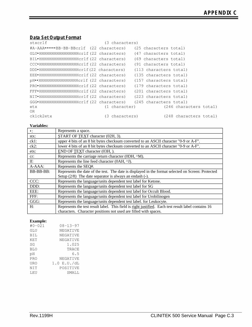
APPENDIX C
Rev.1199H CLINITEK 500 Service Manual Page C.3
Data Set Output Formatstxcrlf (3 characters)#A-AAA••••••BB-BB-BBcrlf (22 characters) (25 characters total)GLU•HHHHHHHHHHHHHHHHcrlf(22 characters) (47 characters total)BIL•HHHHHHHHHHHHHHHHcrlf(22 characters) (69 characters total)CCC•HHHHHHHHHHHHHHHHcrlf(22 characters) (91 characters total)DDD•HHHHHHHHHHHHHHHHcrlf(22 characters) (113 characters total)EEE•HHHHHHHHHHHHHHHHcrlf(22 characters) (135 characters total)pH••HHHHHHHHHHHHHHHHcrlf (22 characters) (157 characters total)PRO•HHHHHHHHHHHHHHHHcrlf(22 characters) (179 characters total)FFF•HHHHHHHHHHHHHHHHcrlf(22 characters) (201 characters total)NIT•HHHHHHHHHHHHHHHHcrlf(22 characters) (223 characters total)GGG•HHHHHHHHHHHHHHHHcrlf(22 characters) (245 characters total)etx (1 character) (246 characters total)ORck1ck2etx (3 characters) (248 characters total)
Variables:•: Represents a space.stx: START OF TEXT character (02H, 3).ck1: upper 4 bits of an 8 bit bytes checksum converted to an ASCII character "0-9 or A-F".ck2: lower 4 bits of an 8 bit bytes checksum converted to an ASCII character "0-9 or A-F".etx: END OF TEXT character (03H, ).cr: Represents the carriage return character (0DH, ^M).lf: Represents the line feed character (0AH, ^J).A-AAA: Represents the SEQ#.BB-BB-BB: Represents the date of the test. The date is displayed in the format selected on Screen: Protected
Setup (2/8) The date separator is always an endash (-).CCC: Represents the language/units dependent test label for Ketone.DDD: Represents the language/units dependent test label for SGEEE: Represents the language/units dependent test label for Occult Blood.FFF: Represents the language/units dependent test label for UrobilinogenGGG: Represents the language/units dependent test label. for Leukocyte.H: Represents the test result label. This field is right justified. Each test result label contains 16
characters. Character positions not used are filled with spaces.
Example:#0-021 08-13-97GLU NEGATIVEBIL NEGATIVEKET NEGATIVESG 1.025BLO TRACEpH 6.5PRO NEGATIVEURO 1.0 E.U./dLNIT POSITIVELEU SMALL
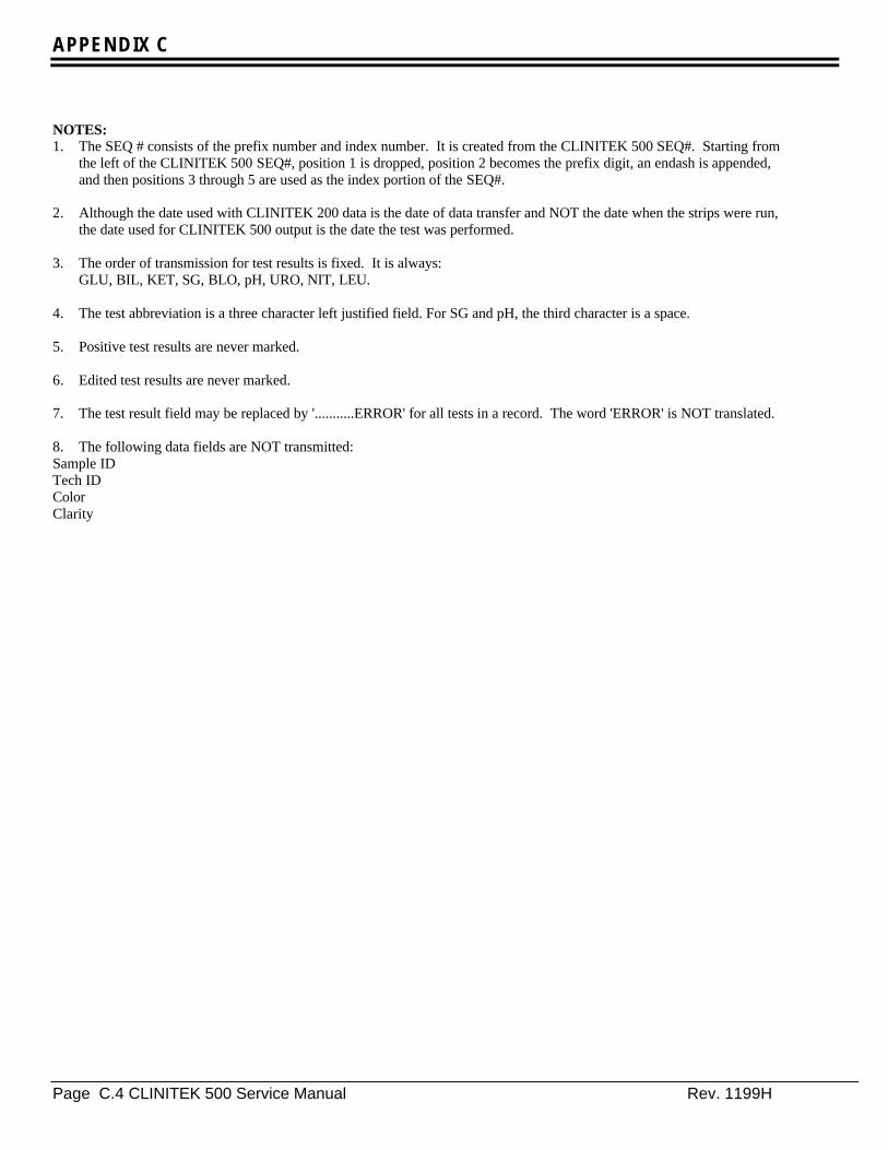
APPENDIX C
Page C.4 CLINITEK 500 Service Manual Rev. 1199H
NOTES:1. The SEQ # consists of the prefix number and index number. It is created from the CLINITEK 500 SEQ#. Starting from
the left of the CLINITEK 500 SEQ#, position 1 is dropped, position 2 becomes the prefix digit, an endash is appended,and then positions 3 through 5 are used as the index portion of the SEQ#.
2. Although the date used with CLINITEK 200 data is the date of data transfer and NOT the date when the strips were run,
the date used for CLINITEK 500 output is the date the test was performed. 3. The order of transmission for test results is fixed. It is always:
GLU, BIL, KET, SG, BLO, pH, URO, NIT, LEU. 4. The test abbreviation is a three character left justified field. For SG and pH, the third character is a space. 5. Positive test results are never marked. 6. Edited test results are never marked. 7. The test result field may be replaced by '...........ERROR' for all tests in a record. The word 'ERROR' is NOT translated. 8. The following data fields are NOT transmitted: Sample ID Tech ID ColorClarity
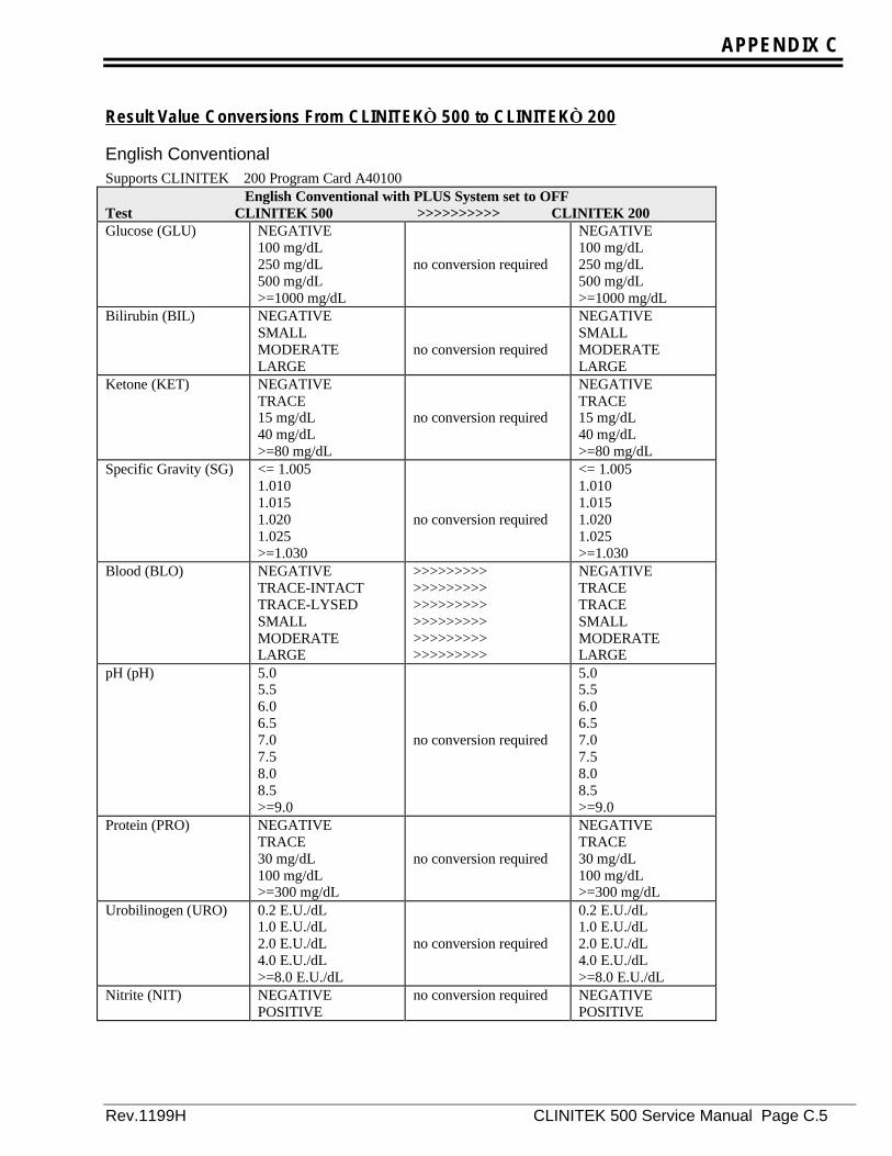
APPENDIX C
Rev.1199H CLINITEK 500 Service Manual Page C.5
Result Value Conversions From CLINITEK 500 to CLINITEK 200
English ConventionalSupports CLINITEK 200 Program Card A40100
English Conventional with PLUS System set to OFFTest CLINITEK 500 >>>>>>>>>> CLINITEK 200Glucose (GLU) NEGATIVE
100 mg/dL250 mg/dL500 mg/dL>=1000 mg/dL
no conversion required
NEGATIVE100 mg/dL250 mg/dL500 mg/dL>=1000 mg/dL
Bilirubin (BIL) NEGATIVESMALLMODERATELARGE
no conversion required
NEGATIVESMALLMODERATELARGE
Ketone (KET) NEGATIVETRACE15 mg/dL40 mg/dL>=80 mg/dL
no conversion required
NEGATIVETRACE15 mg/dL40 mg/dL>=80 mg/dL
Specific Gravity (SG) <= 1.0051.0101.0151.0201.025>=1.030
no conversion required
<= 1.0051.0101.0151.0201.025>=1.030
Blood (BLO) NEGATIVETRACE-INTACTTRACE-LYSEDSMALLMODERATELARGE
>>>>>>>>>>>>>>>>>>>>>>>>>>>>>>>>>>>>>>>>>>>>>>>>>>>>>>
NEGATIVETRACETRACESMALLMODERATELARGE
pH (pH) 5.05.56.06.57.07.58.08.5>=9.0
no conversion required
5.05.56.06.57.07.58.08.5>=9.0
Protein (PRO) NEGATIVETRACE30 mg/dL100 mg/dL>=300 mg/dL
no conversion required
NEGATIVETRACE30 mg/dL100 mg/dL>=300 mg/dL
Urobilinogen (URO) 0.2 E.U./dL1.0 E.U./dL2.0 E.U./dL4.0 E.U./dL>=8.0 E.U./dL
no conversion required
0.2 E.U./dL1.0 E.U./dL2.0 E.U./dL4.0 E.U./dL>=8.0 E.U./dL
Nitrite (NIT) NEGATIVEPOSITIVE
no conversion required NEGATIVEPOSITIVE
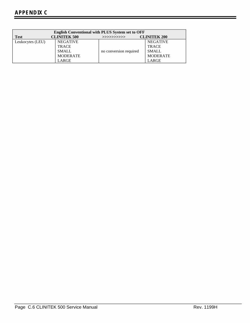
APPENDIX C
Page C.6 CLINITEK 500 Service Manual Rev. 1199H
English Conventional with PLUS System set to OFFTest CLINITEK 500 >>>>>>>>>> CLINITEK 200Leukocytes (LEU) NEGATIVE
TRACESMALLMODERATELARGE
no conversion required
NEGATIVETRACESMALLMODERATELARGE
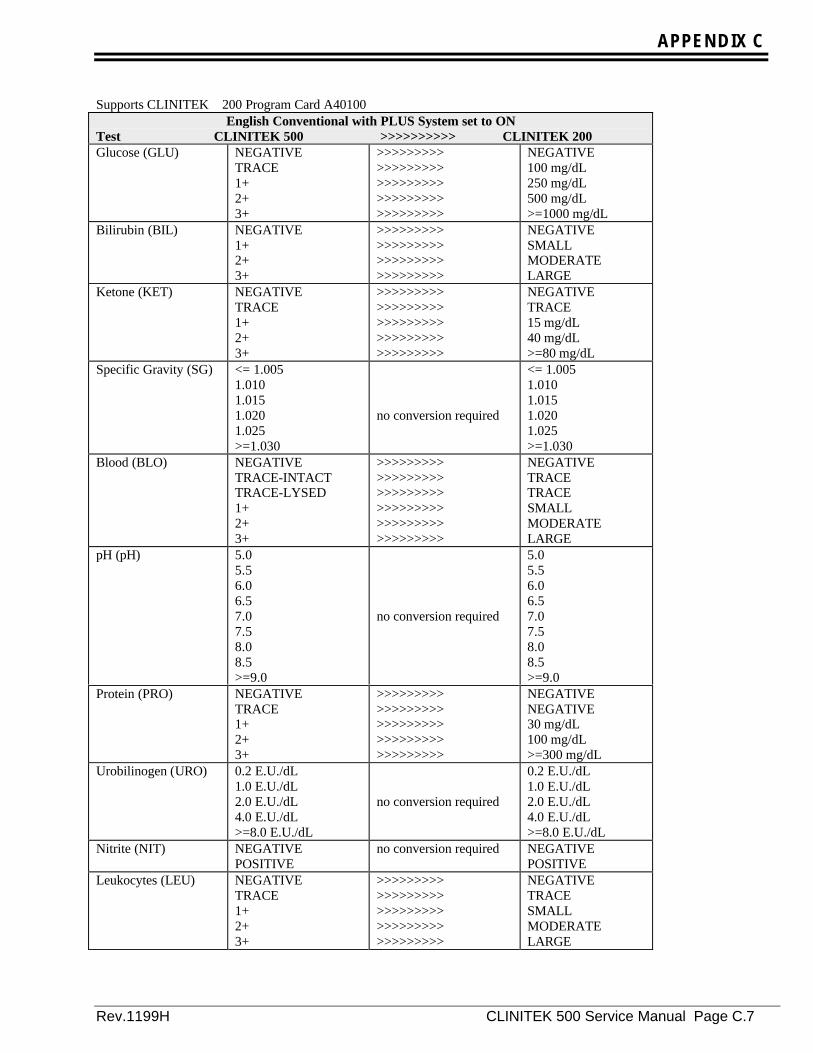
APPENDIX C
Rev.1199H CLINITEK 500 Service Manual Page C.7
Supports CLINITEK 200 Program Card A40100English Conventional with PLUS System set to ON
Test CLINITEK 500 >>>>>>>>>> CLINITEK 200Glucose (GLU) NEGATIVE
TRACE1+2+3+
>>>>>>>>>>>>>>>>>>>>>>>>>>>>>>>>>>>>>>>>>>>>>
NEGATIVE100 mg/dL250 mg/dL500 mg/dL>=1000 mg/dL
Bilirubin (BIL) NEGATIVE1+2+3+
>>>>>>>>>>>>>>>>>>>>>>>>>>>>>>>>>>>>
NEGATIVESMALLMODERATELARGE
Ketone (KET) NEGATIVETRACE1+2+3+
>>>>>>>>>>>>>>>>>>>>>>>>>>>>>>>>>>>>>>>>>>>>>
NEGATIVETRACE15 mg/dL40 mg/dL>=80 mg/dL
Specific Gravity (SG) <= 1.0051.0101.0151.0201.025>=1.030
no conversion required
<= 1.0051.0101.0151.0201.025>=1.030
Blood (BLO) NEGATIVETRACE-INTACTTRACE-LYSED1+2+3+
>>>>>>>>>>>>>>>>>>>>>>>>>>>>>>>>>>>>>>>>>>>>>>>>>>>>>>
NEGATIVETRACETRACESMALLMODERATELARGE
pH (pH) 5.05.56.06.57.07.58.08.5>=9.0
no conversion required
5.05.56.06.57.07.58.08.5>=9.0
Protein (PRO) NEGATIVETRACE1+2+3+
>>>>>>>>>>>>>>>>>>>>>>>>>>>>>>>>>>>>>>>>>>>>>
NEGATIVENEGATIVE30 mg/dL100 mg/dL>=300 mg/dL
Urobilinogen (URO) 0.2 E.U./dL1.0 E.U./dL2.0 E.U./dL4.0 E.U./dL>=8.0 E.U./dL
no conversion required
0.2 E.U./dL1.0 E.U./dL2.0 E.U./dL4.0 E.U./dL>=8.0 E.U./dL
Nitrite (NIT) NEGATIVEPOSITIVE
no conversion required NEGATIVEPOSITIVE
Leukocytes (LEU) NEGATIVETRACE1+2+3+
>>>>>>>>>>>>>>>>>>>>>>>>>>>>>>>>>>>>>>>>>>>>>
NEGATIVETRACESMALLMODERATELARGE
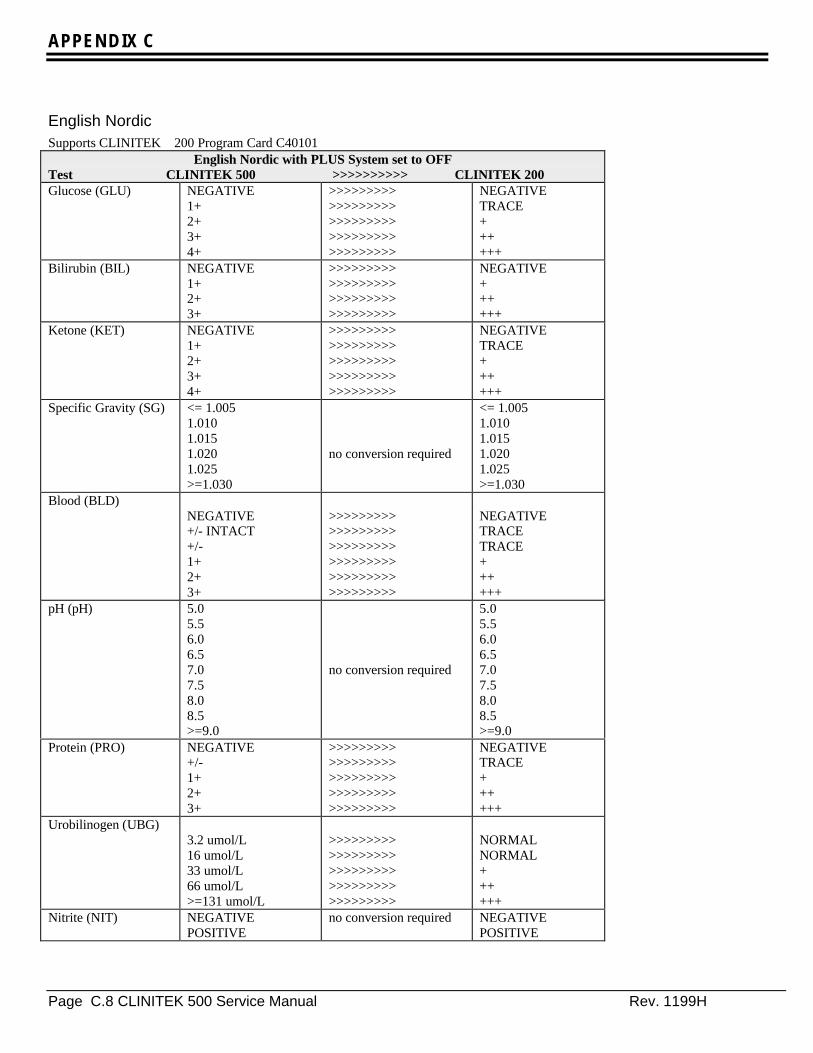
APPENDIX C
Page C.8 CLINITEK 500 Service Manual Rev. 1199H
English NordicSupports CLINITEK 200 Program Card C40101
English Nordic with PLUS System set to OFFTest CLINITEK 500 >>>>>>>>>> CLINITEK 200Glucose (GLU) NEGATIVE
1+2+3+4+
>>>>>>>>>>>>>>>>>>>>>>>>>>>>>>>>>>>>>>>>>>>>>
NEGATIVETRACE++++++
Bilirubin (BIL) NEGATIVE1+2+3+
>>>>>>>>>>>>>>>>>>>>>>>>>>>>>>>>>>>>
NEGATIVE++++++
Ketone (KET) NEGATIVE1+2+3+4+
>>>>>>>>>>>>>>>>>>>>>>>>>>>>>>>>>>>>>>>>>>>>>
NEGATIVETRACE++++++
Specific Gravity (SG) <= 1.0051.0101.0151.0201.025>=1.030
no conversion required
<= 1.0051.0101.0151.0201.025>=1.030
Blood (BLD)NEGATIVE+/- INTACT+/-1+2+3+
>>>>>>>>>>>>>>>>>>>>>>>>>>>>>>>>>>>>>>>>>>>>>>>>>>>>>>
NEGATIVETRACETRACE++++++
pH (pH) 5.05.56.06.57.07.58.08.5>=9.0
no conversion required
5.05.56.06.57.07.58.08.5>=9.0
Protein (PRO) NEGATIVE+/-1+2+3+
>>>>>>>>>>>>>>>>>>>>>>>>>>>>>>>>>>>>>>>>>>>>>
NEGATIVETRACE++++++
Urobilinogen (UBG)3.2 umol/L16 umol/L33 umol/L66 umol/L>=131 umol/L
>>>>>>>>>>>>>>>>>>>>>>>>>>>>>>>>>>>>>>>>>>>>>
NORMALNORMAL++++++
Nitrite (NIT) NEGATIVEPOSITIVE
no conversion required NEGATIVEPOSITIVE

APPENDIX C
Rev.1199H CLINITEK 500 Service Manual Page C.9
English Nordic with PLUS System set to OFFTest CLINITEK 500 >>>>>>>>>> CLINITEK 200Leukocytes (LEU) NEGATIVE
1+2+3+4+
>>>>>>>>>>>>>>>>>>>>>>>>>>>>>>>>>>>>>>>>>>>>>
NEGATIVETRACE++++++
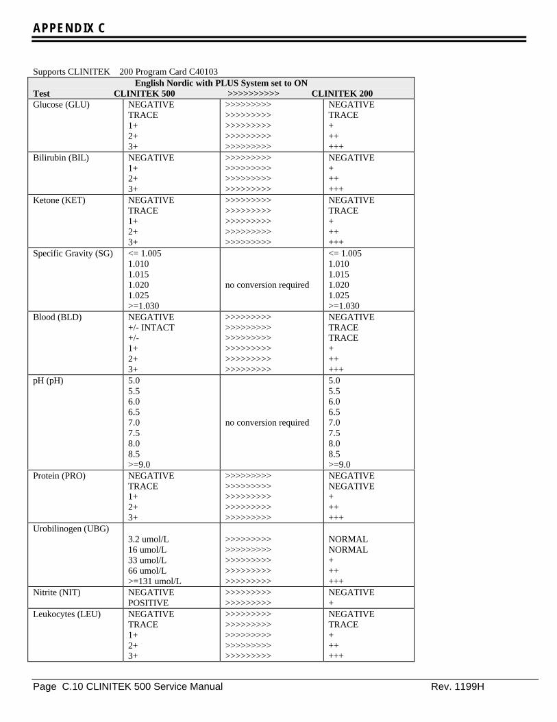
APPENDIX C
Page C.10 CLINITEK 500 Service Manual Rev. 1199H
Supports CLINITEK 200 Program Card C40103English Nordic with PLUS System set to ON
Test CLINITEK 500 >>>>>>>>>> CLINITEK 200Glucose (GLU) NEGATIVE
TRACE1+2+3+
>>>>>>>>>>>>>>>>>>>>>>>>>>>>>>>>>>>>>>>>>>>>>
NEGATIVETRACE++++++
Bilirubin (BIL) NEGATIVE1+2+3+
>>>>>>>>>>>>>>>>>>>>>>>>>>>>>>>>>>>>
NEGATIVE++++++
Ketone (KET) NEGATIVETRACE1+2+3+
>>>>>>>>>>>>>>>>>>>>>>>>>>>>>>>>>>>>>>>>>>>>>
NEGATIVETRACE++++++
Specific Gravity (SG) <= 1.0051.0101.0151.0201.025>=1.030
no conversion required
<= 1.0051.0101.0151.0201.025>=1.030
Blood (BLD) NEGATIVE+/- INTACT+/-1+2+3+
>>>>>>>>>>>>>>>>>>>>>>>>>>>>>>>>>>>>>>>>>>>>>>>>>>>>>>
NEGATIVETRACETRACE++++++
pH (pH) 5.05.56.06.57.07.58.08.5>=9.0
no conversion required
5.05.56.06.57.07.58.08.5>=9.0
Protein (PRO) NEGATIVETRACE1+2+3+
>>>>>>>>>>>>>>>>>>>>>>>>>>>>>>>>>>>>>>>>>>>>>
NEGATIVENEGATIVE++++++
Urobilinogen (UBG)3.2 umol/L16 umol/L33 umol/L66 umol/L>=131 umol/L
>>>>>>>>>>>>>>>>>>>>>>>>>>>>>>>>>>>>>>>>>>>>>
NORMALNORMAL++++++
Nitrite (NIT) NEGATIVEPOSITIVE
>>>>>>>>>>>>>>>>>>
NEGATIVE+
Leukocytes (LEU) NEGATIVETRACE1+2+3+
>>>>>>>>>>>>>>>>>>>>>>>>>>>>>>>>>>>>>>>>>>>>>
NEGATIVETRACE++++++

APPENDIX C
Rev.1199H CLINITEK 500 Service Manual Page C.11
English S.I.Supports CLINITEK 200 Program Card C40104
English S.I. with PLUS System set to OFFTest CLINITEK 500 >>>>>>>>>> CLINITEK 200Glucose (GLU) NEGATIVE
5.5 mmol/L14 mmol/L28 mmol/L>=55 mmol/L
no conversion required
NEGATIVE5.5 mmol/L14 mmol/L28 mmol/L>=55 mmol/L
Bilirubin (BIL) NEGATIVESMALLMODERATELARGE
no conversion required
NEGATIVESMALLMODERATELARGE
Ketone (KET) NEGATIVETRACE1.5 mmol/L3.9 mmol/L>=7.8 mmol/L
no conversion required
NEGATIVETRACE1.5 mmol/L3.9 mmol/L>=7.8 mmol/L
Specific Gravity (SG) <= 1.0051.0101.0151.0201.025>=1.030
no conversion required
<= 1.0051.0101.0151.0201.025>=1.030
Blood (BLD) NEGATIVETRACE-INTACTTRACE-LYSEDCa 25 Ery/uLCa 80 Ery/uLCa 200 Ery/uL
>>>>>>>>>>>>>>>>>>>>>>>>>>>>>>>>>>>>>>>>>>>>>>>>>>>>>>
NEGATIVETRACETRACESMALLMODERATELARGE
pH (pH) 5.05.56.06.57.07.58.08.5>=9.0
no conversion required
5.05.56.06.57.07.58.08.5>=9.0
Protein (PRO) NEGATIVETRACE0.3 g/L1.0 g/L>=3.0 g/L
no conversion required
NEGATIVETRACE0.3 g/L1.0 g/L>=3.0 g/L
Urobilinogen (UBG) 3.2 umol/L16 umol/L33 umol/L66 umol/L>=131 umol/L
no conversion required
3.2 umol/L16 umol/L33 umol/L66 umol/L>=131 umol/L
Nitrite (NIT) NEGATIVEPOSITIVE
no conversion required NEGATIVEPOSITIVE
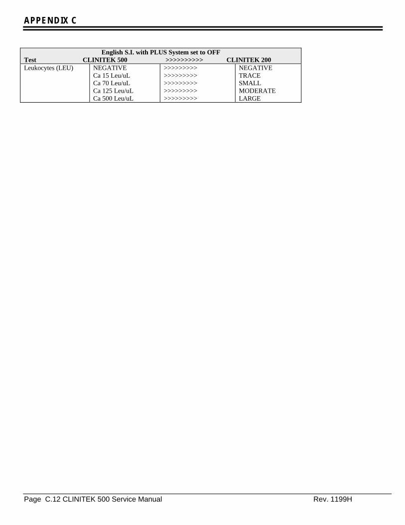
APPENDIX C
Page C.12 CLINITEK 500 Service Manual Rev. 1199H
English S.I. with PLUS System set to OFFTest CLINITEK 500 >>>>>>>>>> CLINITEK 200Leukocytes (LEU) NEGATIVE
Ca 15 Leu/uLCa 70 Leu/uLCa 125 Leu/uLCa 500 Leu/uL
>>>>>>>>>>>>>>>>>>>>>>>>>>>>>>>>>>>>>>>>>>>>>
NEGATIVETRACESMALLMODERATELARGE

APPENDIX C
Rev.1199H CLINITEK 500 Service Manual Page C.13
Supports CLINITEK 200 Program Card C40102English S.I. with PLUS System set to ON
Test CLINITEK 500 >>>>>>>>>> CLINITEK 200Glucose (GLU) NEGATIVE
TRACE1+2+3+
>>>>>>>>>>>>>>>>>>>>>>>>>>>>>>>>>>>>>>>>>>>>>
NEGATIVE++++++++
Bilirubin (BIL) NEGATIVE1+2+3+
>>>>>>>>>>>>>>>>>>>>>>>>>>>>>>>>>>>>
NEGATIVESMALLMODERATELARGE
Ketone (KET) NEGATIVETRACE1+2+3+
>>>>>>>>>>>>>>>>>>>>>>>>>>>>>>>>>>>>>>>>>>>>>
NEGATIVE+++++++
Specific Gravity (SG) <= 1.0051.0101.0151.0201.025>=1.030
no conversion required
<= 1.0051.0101.0151.0201.025>=1.030
Blood (BLD) NEGATIVETRACE-INTACTTRACE-LYSED1+2+3+
>>>>>>>>>>>>>>>>>>>>>>>>>>>>>>>>>>>>>>>>>>>>>>>>>>>>>>
NEGATIVE++++++++
pH (pH) 5.05.56.06.57.07.58.08.5>=9.0
no conversion required
5.05.56.06.57.07.58.08.5>=9.0
Protein (PRO) NEGATIVETRACE1+2+3+
>>>>>>>>>>>>>>>>>>>>>>>>>>>>>>>>>>>>>>>>>>>>>
NEGATIVENEGATIVE++++++
Urobilinogen (UBG) 3.2 umol/L16 umol/L33 umol/L66 umol/L>=131 umol/L
no conversion required
3.2 umol/L16 umol/L33 umol/L66 umol/L>=131 umol/L
Nitrite (NIT) NEGATIVEPOSITIVE
>>>>>>>>>>>>>>>>>>
NEGATIVE+
Leukocytes (LEU) NEGATIVETRACE1+2+3+
>>>>>>>>>>>>>>>>>>>>>>>>>>>>>>>>>>>>>>>>>>>>>
NEGATIVE+++++++
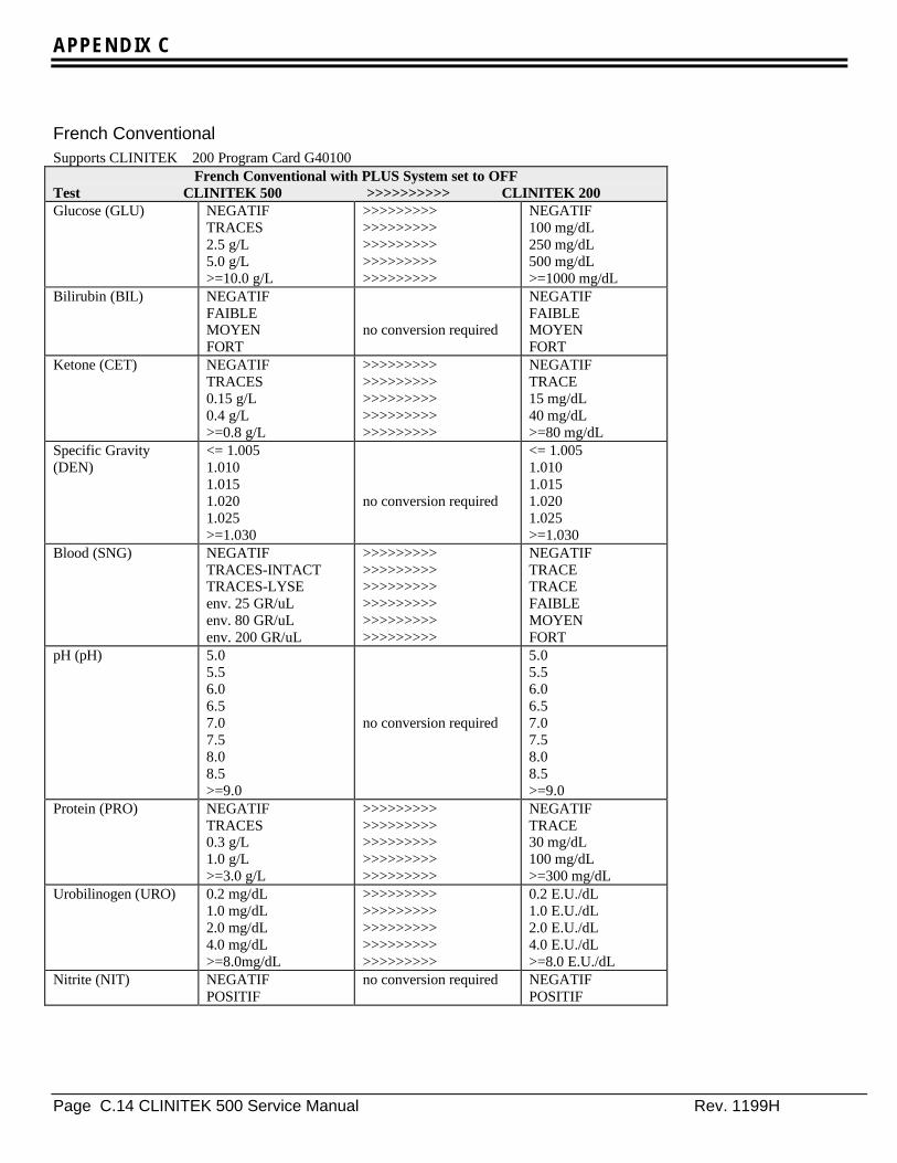
APPENDIX C
Page C.14 CLINITEK 500 Service Manual Rev. 1199H
French ConventionalSupports CLINITEK 200 Program Card G40100
French Conventional with PLUS System set to OFFTest CLINITEK 500 >>>>>>>>>> CLINITEK 200Glucose (GLU) NEGATIF
TRACES2.5 g/L5.0 g/L>=10.0 g/L
>>>>>>>>>>>>>>>>>>>>>>>>>>>>>>>>>>>>>>>>>>>>>
NEGATIF100 mg/dL250 mg/dL500 mg/dL>=1000 mg/dL
Bilirubin (BIL) NEGATIFFAIBLEMOYENFORT
no conversion required
NEGATIFFAIBLEMOYENFORT
Ketone (CET) NEGATIFTRACES0.15 g/L0.4 g/L>=0.8 g/L
>>>>>>>>>>>>>>>>>>>>>>>>>>>>>>>>>>>>>>>>>>>>>
NEGATIFTRACE15 mg/dL40 mg/dL>=80 mg/dL
Specific Gravity(DEN)
<= 1.0051.0101.0151.0201.025>=1.030
no conversion required
<= 1.0051.0101.0151.0201.025>=1.030
Blood (SNG) NEGATIFTRACES-INTACTTRACES-LYSEenv. 25 GR/uLenv. 80 GR/uLenv. 200 GR/uL
>>>>>>>>>>>>>>>>>>>>>>>>>>>>>>>>>>>>>>>>>>>>>>>>>>>>>>
NEGATIFTRACETRACEFAIBLEMOYENFORT
pH (pH) 5.05.56.06.57.07.58.08.5>=9.0
no conversion required
5.05.56.06.57.07.58.08.5>=9.0
Protein (PRO) NEGATIFTRACES0.3 g/L1.0 g/L>=3.0 g/L
>>>>>>>>>>>>>>>>>>>>>>>>>>>>>>>>>>>>>>>>>>>>>
NEGATIFTRACE30 mg/dL100 mg/dL>=300 mg/dL
Urobilinogen (URO) 0.2 mg/dL1.0 mg/dL2.0 mg/dL4.0 mg/dL>=8.0mg/dL
>>>>>>>>>>>>>>>>>>>>>>>>>>>>>>>>>>>>>>>>>>>>>
0.2 E.U./dL1.0 E.U./dL2.0 E.U./dL4.0 E.U./dL>=8.0 E.U./dL
Nitrite (NIT) NEGATIFPOSITIF
no conversion required NEGATIFPOSITIF
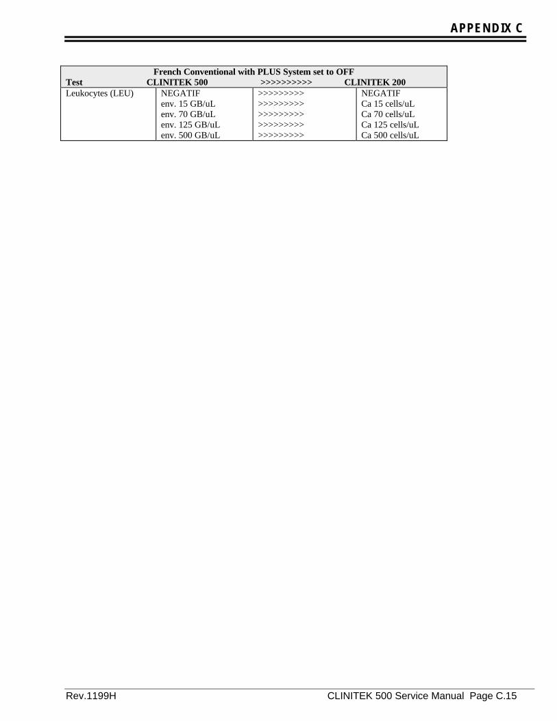
APPENDIX C
Rev.1199H CLINITEK 500 Service Manual Page C.15
French Conventional with PLUS System set to OFFTest CLINITEK 500 >>>>>>>>>> CLINITEK 200Leukocytes (LEU) NEGATIF
env. 15 GB/uLenv. 70 GB/uLenv. 125 GB/uLenv. 500 GB/uL
>>>>>>>>>>>>>>>>>>>>>>>>>>>>>>>>>>>>>>>>>>>>>
NEGATIFCa 15 cells/uLCa 70 cells/uLCa 125 cells/uLCa 500 cells/uL
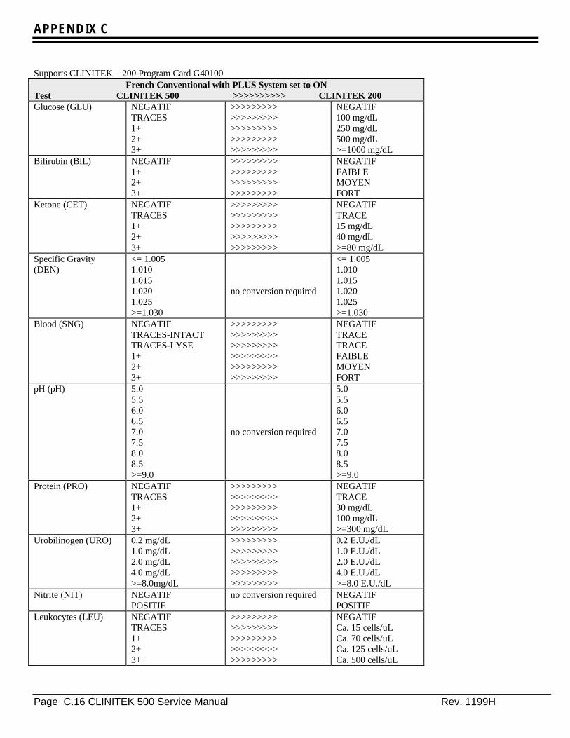
APPENDIX C
Page C.16 CLINITEK 500 Service Manual Rev. 1199H
Supports CLINITEK 200 Program Card G40100French Conventional with PLUS System set to ON
Test CLINITEK 500 >>>>>>>>>> CLINITEK 200Glucose (GLU) NEGATIF
TRACES1+2+3+
>>>>>>>>>>>>>>>>>>>>>>>>>>>>>>>>>>>>>>>>>>>>>
NEGATIF100 mg/dL250 mg/dL500 mg/dL>=1000 mg/dL
Bilirubin (BIL) NEGATIF1+2+3+
>>>>>>>>>>>>>>>>>>>>>>>>>>>>>>>>>>>>
NEGATIFFAIBLEMOYENFORT
Ketone (CET) NEGATIFTRACES1+2+3+
>>>>>>>>>>>>>>>>>>>>>>>>>>>>>>>>>>>>>>>>>>>>>
NEGATIFTRACE15 mg/dL40 mg/dL>=80 mg/dL
Specific Gravity(DEN)
<= 1.0051.0101.0151.0201.025>=1.030
no conversion required
<= 1.0051.0101.0151.0201.025>=1.030
Blood (SNG) NEGATIFTRACES-INTACTTRACES-LYSE1+2+3+
>>>>>>>>>>>>>>>>>>>>>>>>>>>>>>>>>>>>>>>>>>>>>>>>>>>>>>
NEGATIFTRACETRACEFAIBLEMOYENFORT
pH (pH) 5.05.56.06.57.07.58.08.5>=9.0
no conversion required
5.05.56.06.57.07.58.08.5>=9.0
Protein (PRO) NEGATIFTRACES1+2+3+
>>>>>>>>>>>>>>>>>>>>>>>>>>>>>>>>>>>>>>>>>>>>>
NEGATIFTRACE30 mg/dL100 mg/dL>=300 mg/dL
Urobilinogen (URO) 0.2 mg/dL1.0 mg/dL2.0 mg/dL4.0 mg/dL>=8.0mg/dL
>>>>>>>>>>>>>>>>>>>>>>>>>>>>>>>>>>>>>>>>>>>>>
0.2 E.U./dL1.0 E.U./dL2.0 E.U./dL4.0 E.U./dL>=8.0 E.U./dL
Nitrite (NIT) NEGATIFPOSITIF
no conversion required NEGATIFPOSITIF
Leukocytes (LEU) NEGATIFTRACES1+2+3+
>>>>>>>>>>>>>>>>>>>>>>>>>>>>>>>>>>>>>>>>>>>>>
NEGATIFCa. 15 cells/uLCa. 70 cells/uLCa. 125 cells/uLCa. 500 cells/uL

APPENDIX C
Rev.1199H CLINITEK 500 Service Manual Page C.17
French S.I.Support for CLINITEK 200 Program Card H40100
French S.I. with PLUS system set to OFFTest CLINITEK 500 >>>>>>>>>> CLINITEK 200Glucose (GLU) NEGATIF
5.5 mmol/L14 mmol/L28 mmol/L>=55 mmol/L
no conversion required
NEGATIF5.5 mmol/L14 mmol/L28 mmol/L>=55 mmol/L
Bilirubin (BIL) NEGATIFFAIBLEMOYENFORT
no conversion required
NEGATIFFAIBLEMOYENFORT
Ketone (CET) NEGATIFTRACES1.5 mmol/L3.9 mmol/L>=7.8 mmol/L
no conversion required
NEGATIFTRACES1.5 mmol/L3.9 mmol/L>=7.8 mmol/L
Specific Gravity(DEN) <= 1.005
1.0101.0151.0201.025>=1.030
DEN >>>>>>>>> SG
no conversion required
<= 1.0051.0101.0151.0201.025>=1.030
Blood (SNG) NEGATIFTRACES-INTACTTRACES-LYSEFAIBLEMOYENFORT
>>>>>>>>>>>>>>>>>>>>>>>>>>>>>>>>>>>>>>>>>>>>>>>>>>>>>>
NEGATIFENV. 10 GR/uLENV. 10 GR/uLENV. 25 GR/uLENV. 80 GR/uLENV. 200 GR/uL
pH (pH) 5.05.56.06.57.07.58.08.5>=9.0
no conversion required
5.05.56.06.57.07.58.08.5>=9.0
Protein (PRO) NEGATIFTRACES0.3 g/L1.0 g/L>=3.0 g/L
no conversion required
NEGATIFTRACES0.3 g/L1.0 g/L>=3.0 g/L
Urobilinogen (URO) 3.2 umol/L16 umol/L33 umol/L66 umol/L>=131 umol/L
no conversion required
3.2 umol/L16 umol/L33 umol/L66 umol/L>=131 umol/L
Nitrite (NIT) NEGATIFPOSITIF
no conversion required NEGATIFPOSITIF

APPENDIX C
Page C.18 CLINITEK 500 Service Manual Rev. 1199H
French S.I. with PLUS system set to OFFTest CLINITEK 500 >>>>>>>>>> CLINITEK 200Leukocytes (LEU) NEGATIF
TRACESFAIBLEMOYENFORT
>>>>>>>>>>>>>>>>>>>>>>>>>>>>>>>>>>>>>>>>>>>>>
NEGATIFENV. 15 LEU/uLENV. 70 LEU/uLENV. 125 LEU/uLENV. 500 LEU/uL
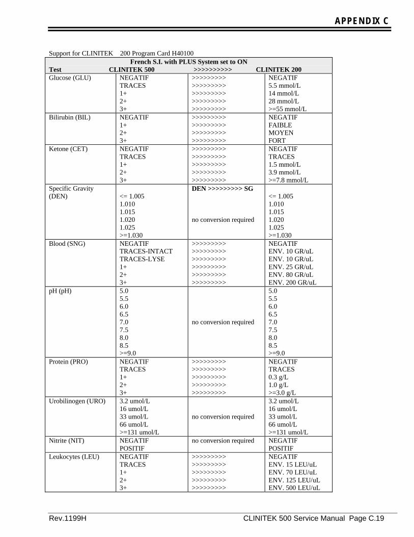
APPENDIX C
Rev.1199H CLINITEK 500 Service Manual Page C.19
Support for CLINITEK 200 Program Card H40100French S.I. with PLUS System set to ON
Test CLINITEK 500 >>>>>>>>>> CLINITEK 200Glucose (GLU) NEGATIF
TRACES1+2+3+
>>>>>>>>>>>>>>>>>>>>>>>>>>>>>>>>>>>>>>>>>>>>>
NEGATIF5.5 mmol/L14 mmol/L28 mmol/L>=55 mmol/L
Bilirubin (BIL) NEGATIF1+2+3+
>>>>>>>>>>>>>>>>>>>>>>>>>>>>>>>>>>>>
NEGATIFFAIBLEMOYENFORT
Ketone (CET) NEGATIFTRACES1+2+3+
>>>>>>>>>>>>>>>>>>>>>>>>>>>>>>>>>>>>>>>>>>>>>
NEGATIFTRACES1.5 mmol/L3.9 mmol/L>=7.8 mmol/L
Specific Gravity(DEN) <= 1.005
1.0101.0151.0201.025>=1.030
DEN >>>>>>>>> SG
no conversion required
<= 1.0051.0101.0151.0201.025>=1.030
Blood (SNG) NEGATIFTRACES-INTACTTRACES-LYSE1+2+3+
>>>>>>>>>>>>>>>>>>>>>>>>>>>>>>>>>>>>>>>>>>>>>>>>>>>>>>
NEGATIFENV. 10 GR/uLENV. 10 GR/uLENV. 25 GR/uLENV. 80 GR/uLENV. 200 GR/uL
pH (pH) 5.05.56.06.57.07.58.08.5>=9.0
no conversion required
5.05.56.06.57.07.58.08.5>=9.0
Protein (PRO) NEGATIFTRACES1+2+3+
>>>>>>>>>>>>>>>>>>>>>>>>>>>>>>>>>>>>>>>>>>>>>
NEGATIFTRACES0.3 g/L1.0 g/L>=3.0 g/L
Urobilinogen (URO) 3.2 umol/L16 umol/L33 umol/L66 umol/L>=131 umol/L
no conversion required
3.2 umol/L16 umol/L33 umol/L66 umol/L>=131 umol/L
Nitrite (NIT) NEGATIFPOSITIF
no conversion required NEGATIFPOSITIF
Leukocytes (LEU) NEGATIFTRACES1+2+3+
>>>>>>>>>>>>>>>>>>>>>>>>>>>>>>>>>>>>>>>>>>>>>
NEGATIFENV. 15 LEU/uLENV. 70 LEU/uLENV. 125 LEU/uLENV. 500 LEU/uL

APPENDIX C
Page C.20 CLINITEK 500 Service Manual Rev. 1199H
German ConventionalSupports CLINITEK 200 Program Card F40100
German Conventional with PLUS System set to OFFTest CLINITEK 500 >>>>>>>>>> CLINITEK 200Glucose (GLU) NEGATIV
100 mg/dL250 mg/dL500 mg/dL>=1000 mg/dL
no conversion required
NEGATIV100 mg/dL250 mg/dL500 mg/dL>=1000 mg/dL
Bilirubin (BIL) NEGATIVSCHWACHMAESSIGSTARK
no conversion required
NEGATIVSCHWACHMAESSIGSTARK
Ketone (KET) NEGATIVSPUR15 mg/dL40 mg/dL>=80 mg/dL
no conversion required
NEGATIVSPUR15 mg/dL40 mg/dL>=80 mg/dL
Specific Gravity (SG) <= 1.0051.0101.0151.0201.025>=1.030
no conversion required
<= 1.0051.0101.0151.0201.025>=1.030
Blood (OBL) 0 Ery/uLCa 10 Ery/uLCa 10 Ery/uLCa 25 Ery/uLCa 80 Ery/uLCa 200 Ery/uL
>>>>>>>>>>>>>>>>>>>>>>>>>>>>>>>>>>>>>>>>>>>>>>>>>>>>>>
0 rbc/uLCa 10 rbc/uLCa 10 rbc/uLCa 25 rbc/uLCa 80 rbc/uLCa 200 rbc/uL
pH (pH) 5.05.56.06.57.07.58.08.5>=9.0
no conversion required
5.05.56.06.57.07.58.08.5>=9.0
Protein (PRO) NEGATIVSPUR30 mg/dL100 mg/dL>=300 mg/dL
no conversion needed
NEGATIVSPUR30 mg/dL100 mg/dL>=300 mg/dL
Urobilinogen (UBG) 0.2 mg/dL1.0 mg/dL2.0 mg/dL4.0 mg/dL>=8.0mg/dL
no conversion needed
0.2 mg/dL1.0 mg/dL2.0 mg/dL4.0 mg/dL>=8.0 mg/dL
Nitrite (NIT) NEGATIVPOSITIV
no conversion needed>>>>>>>>>
NEGATIVPOSITIV

APPENDIX C
Rev.1199H CLINITEK 500 Service Manual Page C.21
German Conventional with PLUS System set to OFFTest CLINITEK 500 >>>>>>>>>> CLINITEK 200Leukocytes (LEU) 0 Leu/uL
Ca 15 Leu/uLCa 70 Leu/uLCa 125 Leu/uLCa 500 Leu/uL
>>>>>>>>>>>>>>>>>>>>>>>>>>>>>>>>>>>>>>>>>>>>>
0 cells/uLCa 15 cells/uLCa 70 cells/uLCa 125 cells/uLCa 500 cells/uL
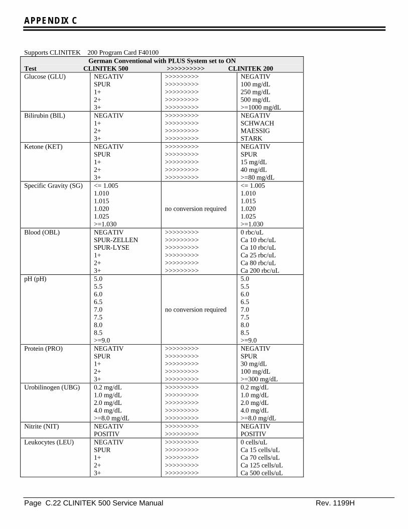
APPENDIX C
Page C.22 CLINITEK 500 Service Manual Rev. 1199H
Supports CLINITEK 200 Program Card F40100German Conventional with PLUS System set to ON
Test CLINITEK 500 >>>>>>>>>> CLINITEK 200Glucose (GLU) NEGATIV
SPUR1+2+3+
>>>>>>>>>>>>>>>>>>>>>>>>>>>>>>>>>>>>>>>>>>>>>
NEGATIV100 mg/dL250 mg/dL500 mg/dL>=1000 mg/dL
Bilirubin (BIL) NEGATIV1+2+3+
>>>>>>>>>>>>>>>>>>>>>>>>>>>>>>>>>>>>
NEGATIVSCHWACHMAESSIGSTARK
Ketone (KET) NEGATIVSPUR1+2+3+
>>>>>>>>>>>>>>>>>>>>>>>>>>>>>>>>>>>>>>>>>>>>>
NEGATIVSPUR15 mg/dL40 mg/dL>=80 mg/dL
Specific Gravity (SG) <= 1.0051.0101.0151.0201.025>=1.030
no conversion required
<= 1.0051.0101.0151.0201.025>=1.030
Blood (OBL) NEGATIVSPUR-ZELLENSPUR-LYSE1+2+3+
>>>>>>>>>>>>>>>>>>>>>>>>>>>>>>>>>>>>>>>>>>>>>>>>>>>>>>
0 rbc/uLCa 10 rbc/uLCa 10 rbc/uLCa 25 rbc/uLCa 80 rbc/uLCa 200 rbc/uL
pH (pH) 5.05.56.06.57.07.58.08.5>=9.0
no conversion required
5.05.56.06.57.07.58.08.5>=9.0
Protein (PRO) NEGATIVSPUR1+2+3+
>>>>>>>>>>>>>>>>>>>>>>>>>>>>>>>>>>>>>>>>>>>>>
NEGATIVSPUR30 mg/dL100 mg/dL>=300 mg/dL
Urobilinogen (UBG) 0.2 mg/dL1.0 mg/dL2.0 mg/dL4.0 mg/dL>=8.0 mg/dL
>>>>>>>>>>>>>>>>>>>>>>>>>>>>>>>>>>>>>>>>>>>>>
0.2 mg/dL1.0 mg/dL2.0 mg/dL4.0 mg/dL>=8.0 mg/dL
Nitrite (NIT) NEGATIVPOSITIV
>>>>>>>>>>>>>>>>>>
NEGATIVPOSITIV
Leukocytes (LEU) NEGATIVSPUR1+2+3+
>>>>>>>>>>>>>>>>>>>>>>>>>>>>>>>>>>>>>>>>>>>>>
0 cells/uLCa 15 cells/uLCa 70 cells/uLCa 125 cells/uLCa 500 cells/uL
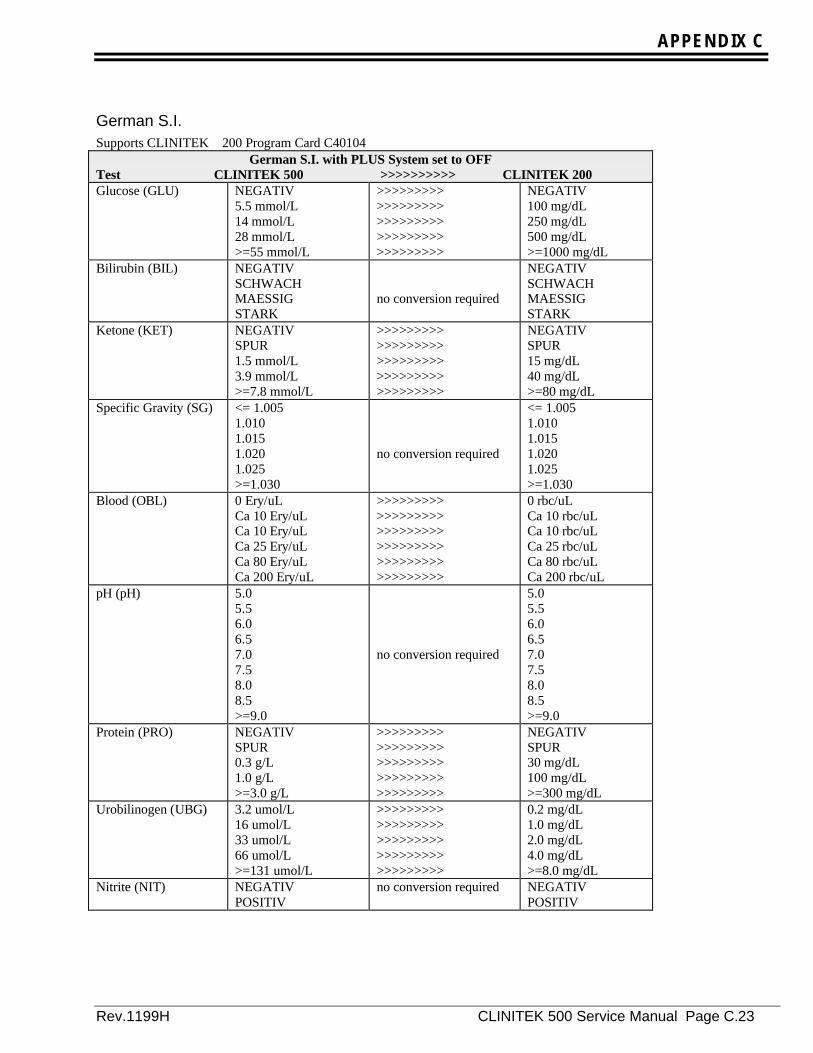
APPENDIX C
Rev.1199H CLINITEK 500 Service Manual Page C.23
German S.I.Supports CLINITEK 200 Program Card C40104
German S.I. with PLUS System set to OFFTest CLINITEK 500 >>>>>>>>>> CLINITEK 200Glucose (GLU) NEGATIV
5.5 mmol/L14 mmol/L28 mmol/L>=55 mmol/L
>>>>>>>>>>>>>>>>>>>>>>>>>>>>>>>>>>>>>>>>>>>>>
NEGATIV100 mg/dL250 mg/dL500 mg/dL>=1000 mg/dL
Bilirubin (BIL) NEGATIVSCHWACHMAESSIGSTARK
no conversion required
NEGATIVSCHWACHMAESSIGSTARK
Ketone (KET) NEGATIVSPUR1.5 mmol/L3.9 mmol/L>=7.8 mmol/L
>>>>>>>>>>>>>>>>>>>>>>>>>>>>>>>>>>>>>>>>>>>>>
NEGATIVSPUR15 mg/dL40 mg/dL>=80 mg/dL
Specific Gravity (SG) <= 1.0051.0101.0151.0201.025>=1.030
no conversion required
<= 1.0051.0101.0151.0201.025>=1.030
Blood (OBL) 0 Ery/uLCa 10 Ery/uLCa 10 Ery/uLCa 25 Ery/uLCa 80 Ery/uLCa 200 Ery/uL
>>>>>>>>>>>>>>>>>>>>>>>>>>>>>>>>>>>>>>>>>>>>>>>>>>>>>>
0 rbc/uLCa 10 rbc/uLCa 10 rbc/uLCa 25 rbc/uLCa 80 rbc/uLCa 200 rbc/uL
pH (pH) 5.05.56.06.57.07.58.08.5>=9.0
no conversion required
5.05.56.06.57.07.58.08.5>=9.0
Protein (PRO) NEGATIVSPUR0.3 g/L1.0 g/L>=3.0 g/L
>>>>>>>>>>>>>>>>>>>>>>>>>>>>>>>>>>>>>>>>>>>>>
NEGATIVSPUR30 mg/dL100 mg/dL>=300 mg/dL
Urobilinogen (UBG) 3.2 umol/L16 umol/L33 umol/L66 umol/L>=131 umol/L
>>>>>>>>>>>>>>>>>>>>>>>>>>>>>>>>>>>>>>>>>>>>>
0.2 mg/dL1.0 mg/dL2.0 mg/dL4.0 mg/dL>=8.0 mg/dL
Nitrite (NIT) NEGATIVPOSITIV
no conversion required NEGATIVPOSITIV
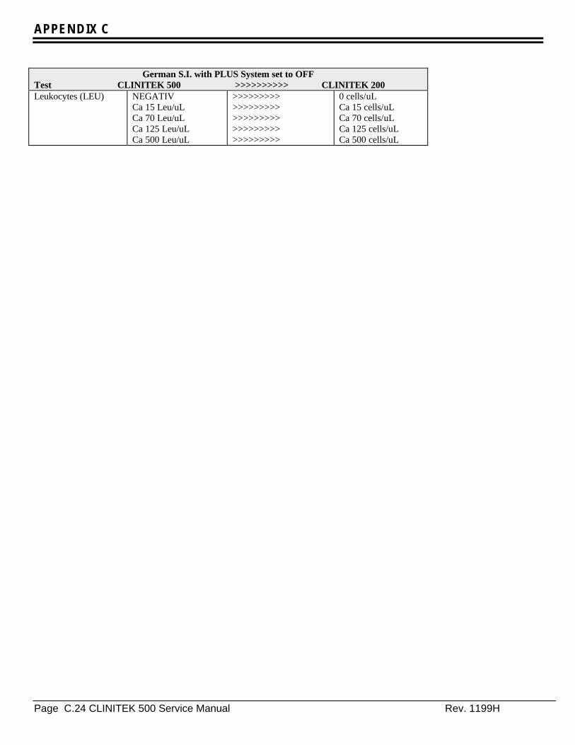
APPENDIX C
Page C.24 CLINITEK 500 Service Manual Rev. 1199H
German S.I. with PLUS System set to OFFTest CLINITEK 500 >>>>>>>>>> CLINITEK 200Leukocytes (LEU) NEGATIV
Ca 15 Leu/uLCa 70 Leu/uLCa 125 Leu/uLCa 500 Leu/uL
>>>>>>>>>>>>>>>>>>>>>>>>>>>>>>>>>>>>>>>>>>>>>
0 cells/uLCa 15 cells/uLCa 70 cells/uLCa 125 cells/uLCa 500 cells/uL

APPENDIX C
Rev.1199H CLINITEK 500 Service Manual Page C.25
Supports CLINITEK 200 Program Card C40104German S.I. with PLUS system set to ON
Test CLINITEK 500 >>>>>>>>>> CLINITEK 200Glucose (GLU) NEGATIV
SPUR1+2+3+
>>>>>>>>>>>>>>>>>>>>>>>>>>>>>>>>>>>>>>>>>>>>>
NEGATIV100 mg/dL250 mg/dL500 mg/dL>=1000 mg/dL
Bilirubin (BIL) NEGATIV1+2+3+
>>>>>>>>>>>>>>>>>>>>>>>>>>>>>>>>>>>>
NEGATIVSCHWACHMAESSIGSTARK
Ketone (KET) NEGATIVSPUR1+2+3+
>>>>>>>>>>>>>>>>>>>>>>>>>>>>>>>>>>>>>>>>>>>>>
NEGATIVSPUR15 mg/dL40 mg/dL>=80 mg/dL
Specific Gravity (SG) <= 1.0051.0101.0151.0201.025>=1.030
no conversion required
<= 1.0051.0101.0151.0201.025>=1.030
Blood (OBL) NEGATIVSPUR-ZELLENSPUR-LYSE1+2+3+
>>>>>>>>>>>>>>>>>>>>>>>>>>>>>>>>>>>>>>>>>>>>>>>>>>>>>>
0 rbc/uLCa 10 rbc/uLCa 10 rbc/uLCa 25 rbc/uLCa 80 rbc/uLCa 200 rbc/uL
pH (pH) 5.05.56.06.57.07.58.08.5>=9.0
no conversion required
5.05.56.06.57.07.58.08.5>=9.0
Protein (PRO) NEGATIVSPUR1+2+3+
>>>>>>>>>>>>>>>>>>>>>>>>>>>>>>>>>>>>>>>>>>>>>
NEGATIVSPUR30 mg/dL100 mg/dL>=300 mg/dL
Urobilinogen (UBG) 3.2 umol/L16 umol/L33 umol/L66 umol/L>=131 umol/L
>>>>>>>>>>>>>>>>>>>>>>>>>>>>>>>>>>>>>>>>>>>>>
0.2 mg/dL1.0 mg/dL2.0 mg/dL4.0 mg/dL>=8.0 mg/dL
Nitrite (NIT) NEGATIVPOSITIV
>>>>>>>>>>>>>>>>>>
NEGATIVPOSITIV
Leukocytes (LEU) NEGATIVSPUR1+2+3+
>>>>>>>>>>>>>>>>>>>>>>>>>>>>>>>>>>>>>>>>>>>>>
0 cells/uLCa 15 cells/uLCa 70 cells/uLCa 125 cells/uLCa 500 cells/uL

APPENDIX C
Page C.26 CLINITEK 500 Service Manual Rev. 1199H
ItalianSupports CLINITEK 200 Program Card E40100
Italian with PLUS System set to OFFTest CLINITEK 500 >>>>>>>>>> CLINITEK 200Glucose (GLU) NEGATIVO
1.0 g/L2.5 g/L5.0 g/L>=10.0 g/L
>>>>>>>>>>>>>>>>>>>>>>>>>>>>>>>>>>>>>>>>>>>>>
NEGATIVO0.1 g/dL0.25 g/dL0.50 g/dL>=1.0 g/dL
Bilirubin (BIL) NEGATIVOLEGGEROMEDIOFORTE
no conversion required
NEGATIVOLEGGEROMEDIOFORTE
Ketone (KET) NEGATIVOTRACCE15 mg/dL40 mg/dL>=80 mg/dL
no conversion required
NEGATIVOTRACCE15 mg/dL40 mg/dL>=80 mg/dL
Specific Gravity (PS) <= 1.0051.0101.0151.0201.025>=1.030
no conversion required
<= 1.0051.0101.0151.0201.025>=1.030
Blood (SAN) NEGATIVOTRACCE(INT.)TRACCE(LIS.)LEGGEROMEDIOFORTE
>>>>>>>>>>>>>>>>>>>>>>>>>>>>>>>>>>>>>>>>>>>>>>>>>>>>>>
NEGATIVOTRACCETRACCELEGGEROMEDIOFORTE
pH (pH) 5.05.56.06.57.07.58.08.5>=9.0
no conversion required
5.05.56.06.57.07.58.08.5>=9.0
Protein (PRO) NEGATIVOTRACCE30 mg/dL100 mg/dL>=300 mg/dL
no conversion required
NEGATIVOTRACCE30 mg/dL100 mg/dL>=300 mg/dL
Urobilinogen (URO) 0.2 E.U./dL1.0 E.U./dL2.0 E.U./dL4.0 E.U./dL>=8.0 E.U./dL
no conversion required
0.2 E.U./dL1.0 E.U./dL2.0 E.U./dL4.0 E.U./dL>=8.0 E.U./dL
Nitrite (NIT) NEGATIVOPOSITIVO
no conversion required NEGATIVOPOSITIVO
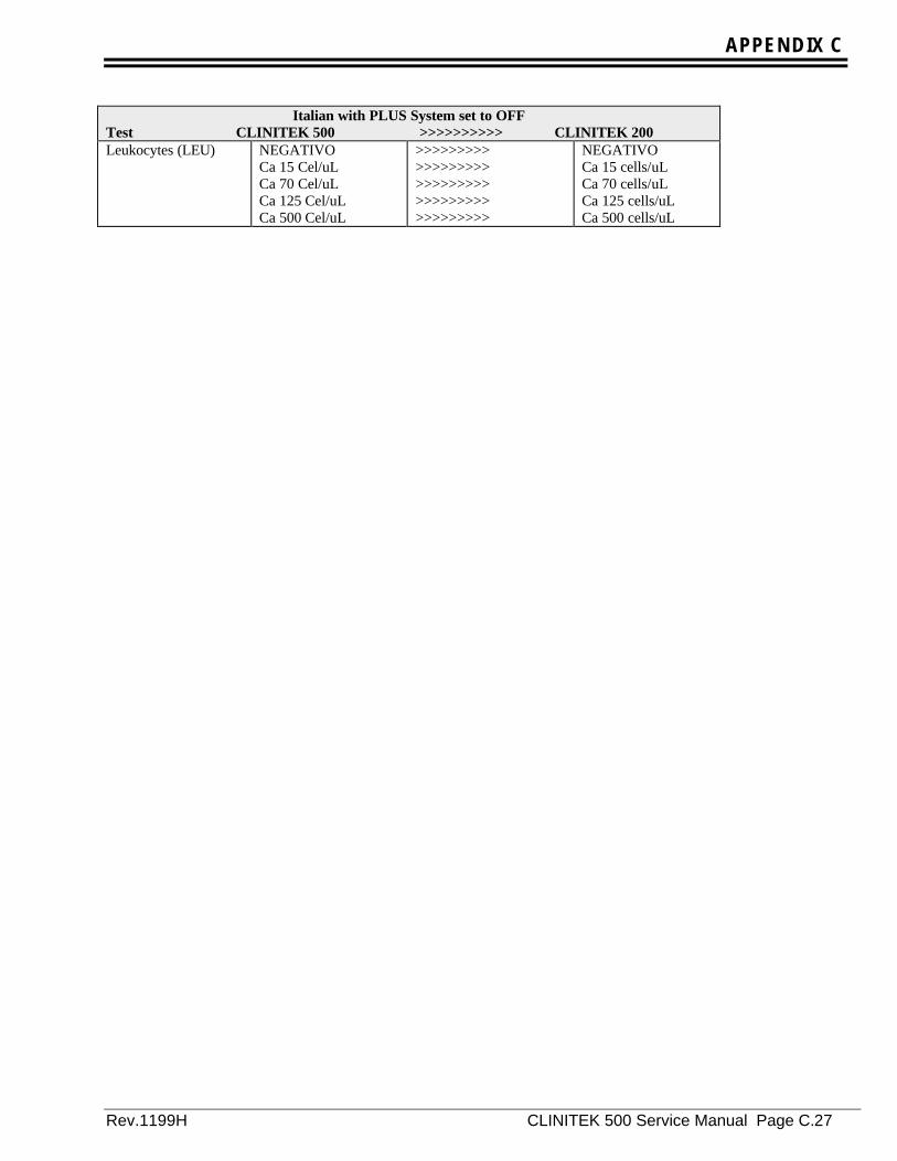
APPENDIX C
Rev.1199H CLINITEK 500 Service Manual Page C.27
Italian with PLUS System set to OFFTest CLINITEK 500 >>>>>>>>>> CLINITEK 200Leukocytes (LEU) NEGATIVO
Ca 15 Cel/uLCa 70 Cel/uLCa 125 Cel/uLCa 500 Cel/uL
>>>>>>>>>>>>>>>>>>>>>>>>>>>>>>>>>>>>>>>>>>>>>
NEGATIVOCa 15 cells/uLCa 70 cells/uLCa 125 cells/uLCa 500 cells/uL

APPENDIX C
Page C.28 CLINITEK 500 Service Manual Rev. 1199H
Supports CLINITEK 200 Program Card E40100Italian with PLUS System set to ON
Test CLINITEK 500 >>>>>>>>>> CLINITEK 200Glucose (GLU) NEGATIVO
TRACCE1+2+3+
>>>>>>>>>>>>>>>>>>>>>>>>>>>>>>>>>>>>>>>>>>>>>
NEGATIVO0.1 g/dL0.25 g/dL0.50 g/dL>=1.0 g/dL
Bilirubin (BIL) NEGATIVO1+2+3+
>>>>>>>>>>>>>>>>>>>>>>>>>>>>>>>>>>>>
NEGATIVOLEGGEROMEDIOFORTE
Ketone (KET) NEGATIVOTRACCE1+2+3+
>>>>>>>>>>>>>>>>>>>>>>>>>>>>>>>>>>>>>>>>>>>>>
NEGATIVOTRACCE15 mg/dL40 mg/dL>=80 mg/dL
Specific Gravity (PS) <= 1.0051.0101.0151.0201.025>=1.030
no conversion required
<= 1.0051.0101.0151.0201.025>=1.030
Blood (SAN) NEGATIVOTRACCE(INT.)TRACCE(LIS.)1+2+3+
>>>>>>>>>>>>>>>>>>>>>>>>>>>>>>>>>>>>>>>>>>>>>>>>>>>>>>
NEGATIVOTRACCETRACCELEGGEROMEDIOFORTE
pH (pH) 5.05.56.06.57.07.58.08.5>=9.0
no conversion required
5.05.56.06.57.07.58.08.5>=9.0
Protein (PRO) NEGATIVOTRACCE1+2+3+
>>>>>>>>>>>>>>>>>>>>>>>>>>>>>>>>>>>>>>>>>>>>>
NEGATIVOTRACCE30 mg/dL100 mg/dL>=300 mg/dL
Urobilinogen (URO) 0.2 E.U./dL1.0 E.U./dL2.0 E.U./dL4.0 E.U./dL>=8.0 E.U./dL
no conversion required
0.2 E.U./dL1.0 E.U./dL2.0 E.U./dL4.0 E.U./dL>=8.0 E.U./dL
Nitrite (NIT) NEGATIVOPOSITIVO
no conversion required NEGATIVOPOSITIVO
Leukocytes (LEU) NEGATIVOTRACCE1+2+3+
>>>>>>>>>>>>>>>>>>>>>>>>>>>>>>>>>>>>>>>>>>>>>
NEGATIVOCa 15 cells/uLCa 70 cells/uLCa 125 cells/uLCa 500 cells/uL

APPENDIX C
Rev.1199H CLINITEK 500 Service Manual Page C.29
KanjiSupports CLINITEK 200 Program Card B40101
Kanji with PLUS system set to OFFTest CLINITEK 500 >>>>>>>>>> CLINITEK 200Glucose (GLU) -
0.1 g/dL0.25 g/dL0.5 g/dL>=1.0 g/dL
no conversion required
-0.1 g/dL0.25 g/dL0.5 g/dL>=1.0 g/dL
Bilirubin (BIL) -1+2+3+
no conversion required
-1+2+3+
Ketone (KET) -+/-1+2+3+
no conversion required
-+/-1+2+3+
Specific Gravity (SG) <= 1.0051.0101.0151.0201.025>=1.030
no conversion required
<= 1.0051.0101.0151.0201.025>=1.030
Blood (OB) -+/-INTACT+/-LYSED1+2+3+
>>>>>>>>>>>>>>>>>>>>>>>>>>>>>>>>>>>>>>>>>>>>>>>>>>>>>>
-+/-+/-1+2+3+
pH (pH) 5.05.56.06.57.07.58.08.5>=9.0
no conversion required
5.05.56.06.57.07.58.08.5>=9.0
Protein (PRO) -+/-30 mg/dL100 mg/dL>=300 mg/dL
no conversion required
-+/-30 mg/dL100 mg/dL>=300 mg/dL
Urobilinogen (URO) 0.1 E.U./dL1.0 E.U./dL2.0 E.U./dL4.0 E.U./dL>=8.0 E.U./dL
no conversion required
0.1 E.U./dL1.0 E.U./dL2.0 E.U./dL4.0 E.U./dL>=8.0 E.U./dL
Nitrite (NIT) -+
no conversion required -+

APPENDIX C
Page C.30 CLINITEK 500 Service Manual Rev. 1199H
Kanji with PLUS system set to OFFTest CLINITEK 500 >>>>>>>>>> CLINITEK 200Leukocytes (WBC) -
+/-1+2+3+
no conversion required
-+/-1+2+3+
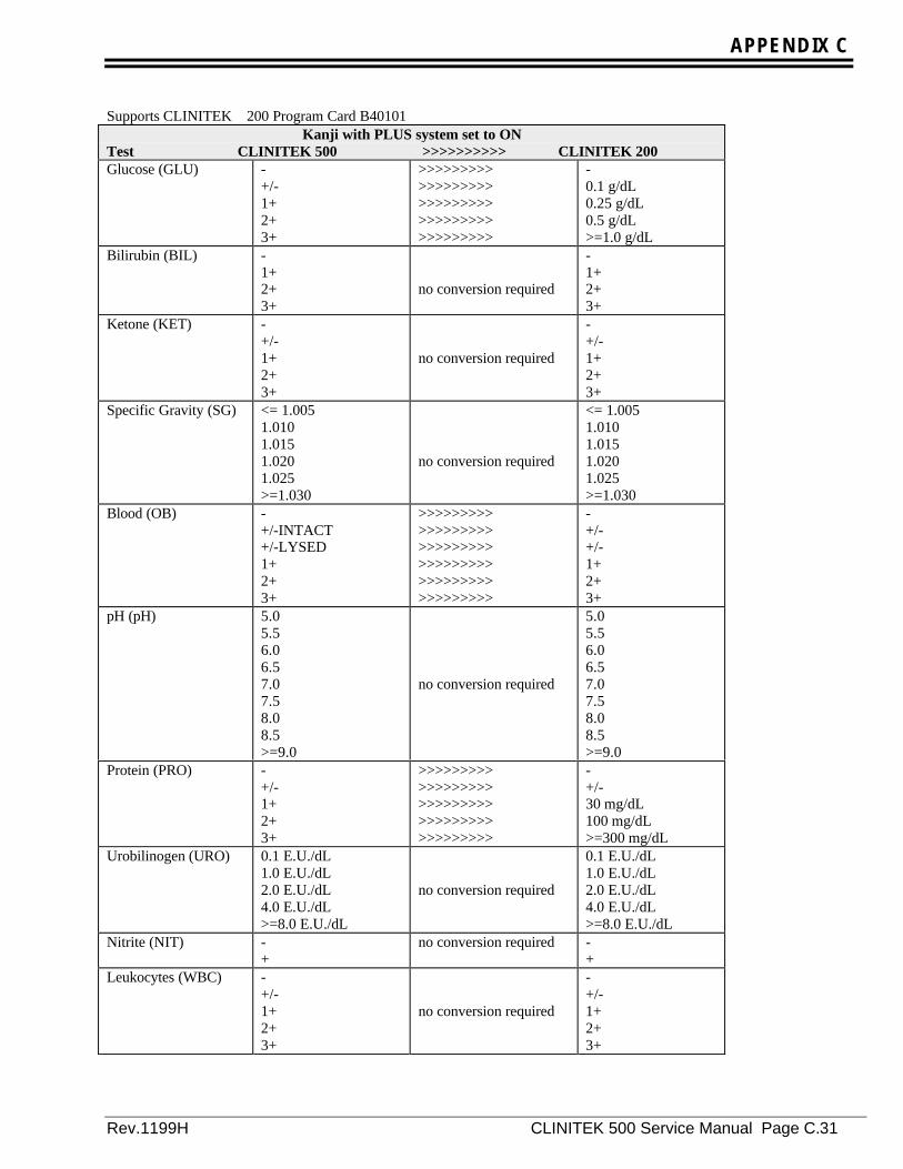
APPENDIX C
Rev.1199H CLINITEK 500 Service Manual Page C.31
Supports CLINITEK 200 Program Card B40101Kanji with PLUS system set to ON
Test CLINITEK 500 >>>>>>>>>> CLINITEK 200Glucose (GLU) -
+/-1+2+3+
>>>>>>>>>>>>>>>>>>>>>>>>>>>>>>>>>>>>>>>>>>>>>
-0.1 g/dL0.25 g/dL0.5 g/dL>=1.0 g/dL
Bilirubin (BIL) -1+2+3+
no conversion required
-1+2+3+
Ketone (KET) -+/-1+2+3+
no conversion required
-+/-1+2+3+
Specific Gravity (SG) <= 1.0051.0101.0151.0201.025>=1.030
no conversion required
<= 1.0051.0101.0151.0201.025>=1.030
Blood (OB) -+/-INTACT+/-LYSED1+2+3+
>>>>>>>>>>>>>>>>>>>>>>>>>>>>>>>>>>>>>>>>>>>>>>>>>>>>>>
-+/-+/-1+2+3+
pH (pH) 5.05.56.06.57.07.58.08.5>=9.0
no conversion required
5.05.56.06.57.07.58.08.5>=9.0
Protein (PRO) -+/-1+2+3+
>>>>>>>>>>>>>>>>>>>>>>>>>>>>>>>>>>>>>>>>>>>>>
-+/-30 mg/dL100 mg/dL>=300 mg/dL
Urobilinogen (URO) 0.1 E.U./dL1.0 E.U./dL2.0 E.U./dL4.0 E.U./dL>=8.0 E.U./dL
no conversion required
0.1 E.U./dL1.0 E.U./dL2.0 E.U./dL4.0 E.U./dL>=8.0 E.U./dL
Nitrite (NIT) -+
no conversion required -+
Leukocytes (WBC) -+/-1+2+3+
no conversion required
-+/-1+2+3+

APPENDIX C
Page C.32 CLINITEK 500 Service Manual Rev. 1199H
SpanishSupports CLINITEK 200 Program Card D40100
Spanish with PLUS system set to OFFTest CLINITEK 500 >>>>>>>>>> CLINITEK 200Glucose (GLU) NEGATIVO
100 mg/dL250 mg/dL500 mg/dL>=1000 mg/dL
no conversion required
NEGATIVO100 mg/dL250 mg/dL500 mg/dL>=1000 mg/dL
Bilirubin (BIL) NEGATIVOBAJOMODERADOALTO
no conversion required
NEGATIVOBAJOMODERADOALTO
Ketone (CET) NEGATIVOINDICIOS15 mg/dL40 mg/dL>=80 mg/dL
no conversion required
NEGATIVOINDICIOS15 mg/dL40 mg/dL>=80 mg/dL
Specific Gravity(DEN)
<= 1.0051.0101.0151.0201.025>=1.030
no conversion required
<= 1.0051.0101.0151.0201.025>=1.030
Blood (SAN) NEGATIVOIND.INTACTOSIND.HEMOLIZ.Apr 25 Hem/uLApr 80 Hem/uLApr 200 Hem/uL
>>>>>>>>>>>>>>>>>>>>>>>>>>>>>>>>>>>>>>>>>>>>>>>>>>>>>>
NEGATIVOApro 10 ERI/uLApro 10 ERI/uLApro 25 ERI/uLApro 80 ERI/uLApro 200 ERI/uL
pH (pH) 5.05.56.06.57.07.58.08.5>=9.0
no conversion required
5.05.56.06.57.07.58.08.5>=9.0
Protein (PRO) NEGATIVOINDICIOS30 mg/dL100 mg/dL>=300 mg/dL
no conversion required
NEGATIVOINDICIOS30 mg/dL100 mg/dL>=300 mg/dL
Urobilinogen (URO) 0.2 E.U./dL1.0 E.U./dL2.0 E.U./dL4.0 E.U./dL>=8.0 E.U./dL
no conversion required
0.2 E.U./dL1.0 E.U./dL2.0 E.U./dL4.0 E.U./dL>=8.0 E.U./dL
Nitrite (NIT) NEGATIVOPOSITIVO
no conversion required NEGATIVOPOSITIVO

APPENDIX C
Rev.1199H CLINITEK 500 Service Manual Page C.33
Spanish with PLUS system set to OFFTest CLINITEK 500 >>>>>>>>>> CLINITEK 200Leukocytes (LEU) NEGATIVO
Apr 15 Leu/uLApr 70 Leu/uLApr 125 Leu/uLApr 500 Leu/uL
>>>>>>>>>>>>>>>>>>>>>>>>>>>>>>>>>>>>>>>>>>>>>
NEGATIVOApro 15 cel/uLApro 70 cel/uLApro 125 cel/uLApro 500 cel/uL
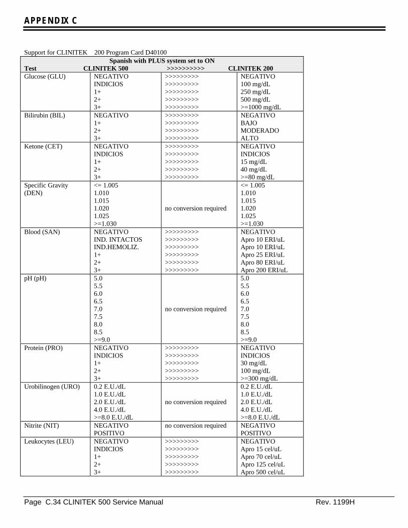
APPENDIX C
Page C.34 CLINITEK 500 Service Manual Rev. 1199H
Support for CLINITEK 200 Program Card D40100Spanish with PLUS system set to ON
Test CLINITEK 500 >>>>>>>>>> CLINITEK 200Glucose (GLU) NEGATIVO
INDICIOS1+2+3+
>>>>>>>>>>>>>>>>>>>>>>>>>>>>>>>>>>>>>>>>>>>>>
NEGATIVO100 mg/dL250 mg/dL500 mg/dL>=1000 mg/dL
Bilirubin (BIL) NEGATIVO1+2+3+
>>>>>>>>>>>>>>>>>>>>>>>>>>>>>>>>>>>>
NEGATIVOBAJOMODERADOALTO
Ketone (CET) NEGATIVOINDICIOS1+2+3+
>>>>>>>>>>>>>>>>>>>>>>>>>>>>>>>>>>>>>>>>>>>>>
NEGATIVOINDICIOS15 mg/dL40 mg/dL>=80 mg/dL
Specific Gravity(DEN)
<= 1.0051.0101.0151.0201.025>=1.030
no conversion required
<= 1.0051.0101.0151.0201.025>=1.030
Blood (SAN) NEGATIVOIND. INTACTOSIND.HEMOLIZ.1+2+3+
>>>>>>>>>>>>>>>>>>>>>>>>>>>>>>>>>>>>>>>>>>>>>>>>>>>>>>
NEGATIVOApro 10 ERI/uLApro 10 ERI/uLApro 25 ERI/uLApro 80 ERI/uLApro 200 ERI/uL
pH (pH) 5.05.56.06.57.07.58.08.5>=9.0
no conversion required
5.05.56.06.57.07.58.08.5>=9.0
Protein (PRO) NEGATIVOINDICIOS1+2+3+
>>>>>>>>>>>>>>>>>>>>>>>>>>>>>>>>>>>>>>>>>>>>>
NEGATIVOINDICIOS30 mg/dL100 mg/dL>=300 mg/dL
Urobilinogen (URO) 0.2 E.U./dL1.0 E.U./dL2.0 E.U./dL4.0 E.U./dL>=8.0 E.U./dL
no conversion required
0.2 E.U./dL1.0 E.U./dL2.0 E.U./dL4.0 E.U./dL>=8.0 E.U./dL
Nitrite (NIT) NEGATIVOPOSITIVO
no conversion required NEGATIVOPOSITIVO
Leukocytes (LEU) NEGATIVOINDICIOS1+2+3+
>>>>>>>>>>>>>>>>>>>>>>>>>>>>>>>>>>>>>>>>>>>>>
NEGATIVOApro 15 cel/uLApro 70 cel/uLApro 125 cel/uLApro 500 cel/uL
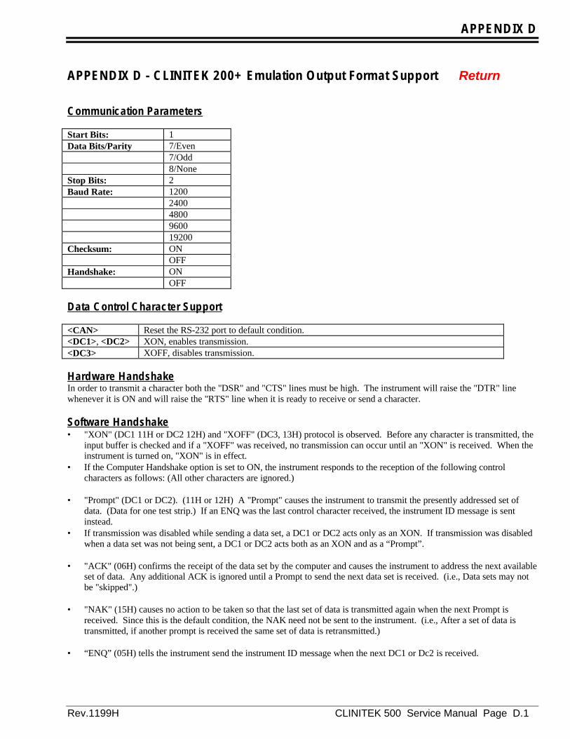
APPENDIX D
Rev.1199H CLINITEK 500 Service Manual Page D.1
APPENDIX D - CLINITEK 200+ Emulation Output Format Support Return
Communication Parameters
Start Bits: 1Data Bits/Parity 7/Even
7/Odd8/None
Stop Bits: 2Baud Rate: 1200
24004800960019200
Checksum: ONOFF
Handshake: ONOFF
Data Control Character Support
<CAN> Reset the RS-232 port to default condition.<DC1>, <DC2> XON, enables transmission.<DC3> XOFF, disables transmission.
Hardware HandshakeIn order to transmit a character both the "DSR" and "CTS" lines must be high. The instrument will raise the "DTR" linewhenever it is ON and will raise the "RTS" line when it is ready to receive or send a character.
Software Handshake• "XON" (DC1 11H or DC2 12H) and "XOFF" (DC3, 13H) protocol is observed. Before any character is transmitted, the
input buffer is checked and if a "XOFF" was received, no transmission can occur until an "XON" is received. When theinstrument is turned on, "XON" is in effect.
• If the Computer Handshake option is set to ON, the instrument responds to the reception of the following controlcharacters as follows: (All other characters are ignored.)
• "Prompt" (DC1 or DC2). (11H or 12H) A "Prompt" causes the instrument to transmit the presently addressed set of
data. (Data for one test strip.) If an ENQ was the last control character received, the instrument ID message is sentinstead.
• If transmission was disabled while sending a data set, a DC1 or DC2 acts only as an XON. If transmission was disabledwhen a data set was not being sent, a DC1 or DC2 acts both as an XON and as a “Prompt”.
• "ACK" (06H) confirms the receipt of the data set by the computer and causes the instrument to address the next available
set of data. Any additional ACK is ignored until a Prompt to send the next data set is received. (i.e., Data sets may notbe "skipped".)
• "NAK" (15H) causes no action to be taken so that the last set of data is transmitted again when the next Prompt is
received. Since this is the default condition, the NAK need not be sent to the instrument. (i.e., After a set of data istransmitted, if another prompt is received the same set of data is retransmitted.)
• “ENQ” (05H) tells the instrument send the instrument ID message when the next DC1 or Dc2 is received.
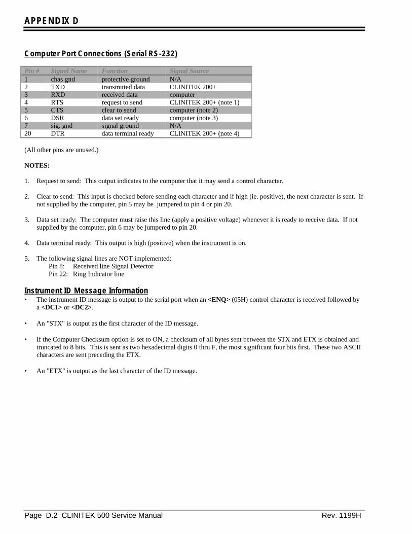
APPENDIX D
Page D.2 CLINITEK 500 Service Manual Rev. 1199H
Computer Port Connections (Serial RS-232)
Pin # Signal Name Function Signal Source1 chas gnd protective ground N/A2 TXD transmitted data CLINITEK 200+3 RXD received data computer4 RTS request to send CLINITEK 200+ (note 1)5 CTS clear to send computer (note 2)6 DSR data set ready computer (note 3)7 sig. gnd signal ground N/A20 DTR data terminal ready CLINITEK 200+ (note 4)
(All other pins are unused.)
NOTES:
1. Request to send: This output indicates to the computer that it may send a control character. 2. Clear to send: This input is checked before sending each character and if high (ie. positive), the next character is sent. If
not supplied by the computer, pin 5 may be jumpered to pin 4 or pin 20. 3. Data set ready: The computer must raise this line (apply a positive voltage) whenever it is ready to receive data. If not
supplied by the computer, pin 6 may be jumpered to pin 20. 4. Data terminal ready: This output is high (positive) when the instrument is on. 5. The following signal lines are NOT implemented:
Pin 8: Received line Signal DetectorPin 22: Ring Indicator line
Instrument ID Message Information• The instrument ID message is output to the serial port when an <ENQ> (05H) control character is received followed by
a <DC1> or <DC2>. • An "STX" is output as the first character of the ID message. • If the Computer Checksum option is set to ON, a checksum of all bytes sent between the STX and ETX is obtained and
truncated to 8 bits. This is sent as two hexadecimal digits 0 thru F, the most significant four bits first. These two ASCIIcharacters are sent preceding the ETX.
• An "ETX" is output as the last character of the ID message.
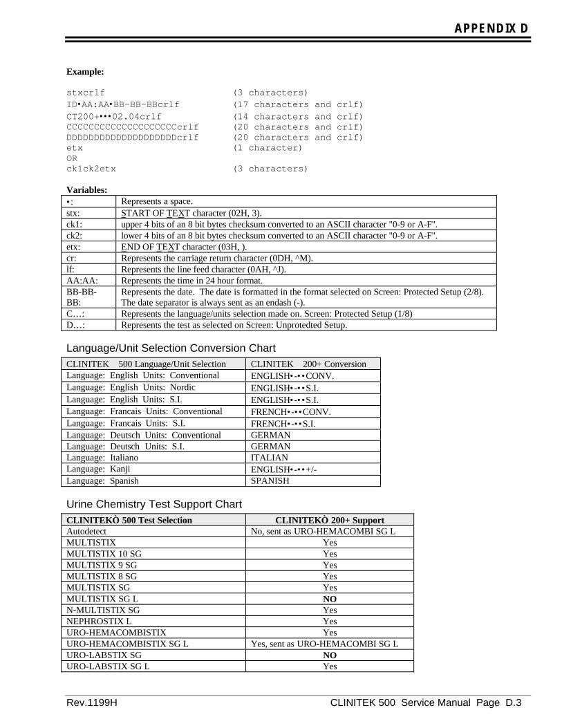
APPENDIX D
Rev.1199H CLINITEK 500 Service Manual Page D.3
Example:
stxcrlf (3 characters)ID•AA:AA•BB-BB-BBcrlf (17 characters and crlf)CT200+•••02.04crlf (14 characters and crlf)CCCCCCCCCCCCCCCCCCCCcrlf (20 characters and crlf)DDDDDDDDDDDDDDDDDDDDcrlf (20 characters and crlf)etx (1 character)ORck1ck2etx (3 characters)
Variables:•: Represents a space.stx: START OF TEXT character (02H, 3).ck1: upper 4 bits of an 8 bit bytes checksum converted to an ASCII character "0-9 or A-F".ck2: lower 4 bits of an 8 bit bytes checksum converted to an ASCII character "0-9 or A-F".etx: END OF TEXT character (03H, ).cr: Represents the carriage return character (0DH, ^M).lf: Represents the line feed character (0AH, ^J).AA:AA: Represents the time in 24 hour format.BB-BB-BB:
Represents the date. The date is formatted in the format selected on Screen: Protected Setup (2/8).The date separator is always sent as an endash (-).
C…: Represents the language/units selection made on. Screen: Protected Setup (1/8)D…: Represents the test as selected on Screen: Unprotedted Setup.
Language/Unit Selection Conversion ChartCLINITEK 500 Language/Unit Selection CLINITEK 200+ ConversionLanguage: English Units: Conventional ENGLISH•-••CONV.Language: English Units: Nordic ENGLISH•-••S.I.Language: English Units: S.I. ENGLISH•-••S.I.Language: Francais Units: Conventional FRENCH•-••CONV.Language: Francais Units: S.I. FRENCH•-••S.I.Language: Deutsch Units: Conventional GERMANLanguage: Deutsch Units: S.I. GERMANLanguage: Italiano ITALIANLanguage: Kanji ENGLISH•-••+/-Language: Spanish SPANISH
Urine Chemistry Test Support ChartCLINITEK 500 Test Selection CLINITEK 200+ SupportAutodetect No, sent as URO-HEMACOMBI SG LMULTISTIX YesMULTISTIX 10 SG YesMULTISTIX 9 SG YesMULTISTIX 8 SG YesMULTISTIX SG YesMULTISTIX SG L NON-MULTISTIX SG YesNEPHROSTIX L YesURO-HEMACOMBISTIX YesURO-HEMACOMBISTIX SG L Yes, sent as URO-HEMACOMBI SG LURO-LABSTIX SG NOURO-LABSTIX SG L Yes

APPENDIX D
Page D.4 CLINITEK 500 Service Manual Rev. 1199H
For the test strips for which the CLINITEK 200+ does not provide support, the ID message will be sent with the selectedtest name. It is the user’s responsibility to ensure that the data collection system can accept the unsupported test strip name.
Data Set Information• Each data set consists of 246 characters (248 characters if the Computer Checksum option is set to ON) if the ‘Enter
Sample ID’ option is set to OFF and 312 characters (314 characters if the Computer Checksum option is set to ON) if the‘Enter Sample ID’ option is set to ON. A data set contains the results for one test strip.
• An "STX" is output as the first character of each set. • If the Computer Checksum option is set to ON, a checksum of all bytes sent between the STX and ETX is obtained and
truncated to 8 bits. This is sent as two hexadecimal digits 0 thru F, the• most significant four bits first. These two ASCII characters are sent preceding the ETX. • An "ETX" is output as the last character of each set.
Data Set Output Format
Enter Sample ID set to OFF
stxcrlf (3 characters)#A-AAA••••••BB-BB-BBcrlf (22 characters) (25 characters total)GLUI••HHHHHHHHHHHHHHcrlf (22 characters) (47 characters total)BILI••HHHHHHHHHHHHHHcrlf (22 characters) (69 characters total)CCCI••HHHHHHHHHHHHHHcrlf (22 characters) (91 characters total)DDI•••HHHHHHHHHHHHHHcrlf (22 characters) (113 characters total)EEEI••HHHHHHHHHHHHHHcrlf (22 characters) (135 characters total)pHI•••HHHHHHHHHHHHHHcrlf (22 characters) (157 characters total)PROI••HHHHHHHHHHHHHHcrlf (22 characters) (179 characters total)FFFI••HHHHHHHHHHHHHHcrlf (22 characters) (201 characters total)NITI••HHHHHHHHHHHHHHcrlf (22 characters) (223 characters total)GGGI••HHHHHHHHHHHHHHcrlf (22 characters) (245 characters total)etx (1 character) (246 characters total)ORck1ck2etx (3 characters) (248 characters total)

APPENDIX D
Rev.1199H CLINITEK 500 Service Manual Page D.5
Enter Sample ID set to ON
stxcrlf (3 characters)#A-AAA••••••BB-BB-BBcrlf (22 characters) (25 characters total)ID=JJJJJJJJJJJJJ••••crlf (22 characters) (47 characters total)Color:•KKKKKKKKKK•••crlf (22 characters) (69 characters total)Clarity:•LLLLLLLLLL•crlf (22 characters) (91 characters total)GLUI••HHHHHHHHHHHHHHcrlf (22 characters) (113 characters total)BILI••HHHHHHHHHHHHHHcrlf (22 characters) (135 characters total)CCCI••HHHHHHHHHHHHHHcrlf (22 characters) (157 characters total)DD••••HHHHHHHHHHHHHHcrlf (22 characters) (179 characters total)EEEI••HHHHHHHHHHHHHHcrlf (22 characters) (201 characters total)pH••••HHHHHHHHHHHHHHcrlf (22 characters) (223 characters total)PROI••HHHHHHHHHHHHHHcrlf (22 characters) (245 characters total)FFFI••HHHHHHHHHHHHHHcrlf (22 characters) (267 characters total)NITI••HHHHHHHHHHHHHHcrlf (22 characters) (289 characters total)GGGI••HHHHHHHHHHHHHHcrlf (22 characters) (311 characters total)etx (1 character) (312 characters total)ORck1ck2etx (3 characters) (314 characters total)
Variables:•: Represents a space.stx: START OF TEXT character (02H, 5).ck1: upper 4 bits of an 8 bit bytes checksum converted to an ASCII character "0-9 or A-F".ck2: lower 4 bits of an 8 bit bytes checksum converted to an ASCII character "0-9 or A-F".etx: END OF TEXT character (03H, ).cr: Represents the carriage return character (0DH, ^M).lf: Represents the line feed character (0AH, ^J).A-AAA: Represents the SEQ#.BB-BB-BB: Represents the date of the test. The date may be displayed in MM-DD-YY, DD-MM-YY, or YY-
MM-DD format.CCC: Represents the language/units dependent test label for Ketone.DD.: Represents the language/units dependent test label for SGEEE: Represents the language/units dependent test label for Occult Blood.FFF: Represents the language/units dependent test label for UrobilinogenGGG: Represents the language/units dependent test label. for Leukocyte.H: Represents the test result label. This field is right justified. Each test result label contains 14
characters. Character positions not used are filled with spaces.I: Sent as an asterisk (*) if the result is positive; otherwise sent as a space.J: Represents the Sample ID. This field is left justified. The Sample ID may be a maximum of 13
alphanumeric characters. Endashes (-) are not supported by the CLINITEK 200+. It is theresponsibility of the user to ensure that the endash is not a part of the ID.
K: Represents the Color value. This field is left justified and contains a maximum of ten characters.L: Represents the Clarity value. This field is left justified and contains a maximum of ten characters.
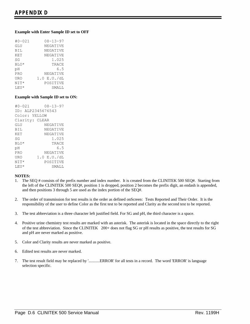
APPENDIX D
Page D.6 CLINITEK 500 Service Manual Rev. 1199H
Example with Enter Sample ID set to OFF
#0-021 08-13-97GLU NEGATIVEBIL NEGATIVEKET NEGATIVESG 1.025BLO* TRACEpH 6.5PRO NEGATIVEURO 1.0 E.U./dLNIT* POSITIVELEU* SMALL
Example with Sample ID set to ON:
#0-021 08-13-97ID: ALP2345676543Color: YELLOWClarity: CLEARGLU NEGATIVEBIL NEGATIVEKET NEGATIVESG 1.025BLO* TRACEpH 6.5PRO NEGATIVEURO 1.0 E.U./dLNIT* POSITIVELEU* SMALL
NOTES:1. The SEQ # consists of the prefix number and index number. It is created from the CLINITEK 500 SEQ#. Starting from
the left of the CLINITEK 500 SEQ#, position 1 is dropped, position 2 becomes the prefix digit, an endash is appended,and then positions 3 through 5 are used as the index portion of the SEQ#.
2. The order of transmission for test results is the order as defined onScreen: Tests Reported and Their Order. It is the
responsibility of the user to define Color as the first test to be reported and Clarity as the second test to be reported. 3. The test abbreviation is a three character left justified field. For SG and pH, the third character is a space. 4. Positive urine chemistry test results are marked with an asterisk. The asterisk is located in the space directly to the right
of the test abbreviation. Since the CLINITEK200+ does not flag SG or pH results as positive, the test results for SGand pH are never marked as positive.
5. Color and Clarity results are never marked as positive. 6. Edited test results are never marked. 7. The test result field may be replaced by '...........ERROR' for all tests in a record. The word 'ERROR' is language
selection specific.

APPENDIX D
Rev.1199H CLINITEK 500 Service Manual Page D.7
8. The Sample ID field does not support the endash (-). It is the responsibility of the user to ensure that the endash is not apart of the ID.
9. The Tech ID data field is NOT transmitted. 10. Sample IDs must be set to ON in order for Color and/or Clarity to be reported.

APPENDIX D
Page D.8 CLINITEK 500 Service Manual Rev. 1199H
Result Value Conversions From CLINITEK 500 to CLINITEK 200+
English ConventionalSupports CLINITEK 200+ Program A4
English Conventional with PLUS System set to OFFTest CLINITEK 500 >>>>>>>>>> CLINITEK 200+Glucose (GLU) NEGATIVE
100 mg/dL250 mg/dL500 mg/dL>=1000 mg/dL
no conversion required
NEGATIVE100 mg/dL250 mg/dL500 mg/dL>=1000 mg/dL
Bilirubin (BIL) NEGATIVESMALLMODERATELARGE
no conversion required
NEGATIVESMALLMODERATELARGE
Ketone (KET) NEGATIVETRACE15 mg/dL40 mg/dL>=80 mg/dL
no conversion required
NEGATIVETRACE15 mg/dL40 mg/dL>=80 mg/dL
Specific Gravity (SG) <= 1.0051.0101.0151.0201.025>=1.030
no conversion required
<= 1.0051.0101.0151.0201.025>=1.030
Blood (BLO) NEGATIVETRACE-INTACTTRACE-LYSEDSMALLMODERATELARGE
>>>>>>>>>>>>>>>>>>>>>>>>>>>>>>>>>>>>>>>>>>>>>>>>>>>>>>
NEGATIVETRACETRACESMALLMODERATELARGE
pH (pH) 5.05.56.06.57.07.58.08.5>=9.0
no conversion required
5.05.56.06.57.07.58.08.5>=9.0
Protein (PRO) NEGATIVETRACE30 mg/dL100 mg/dL>=300 mg/dL
no conversion required
NEGATIVETRACE30 mg/dL100 mg/dL>=300 mg/dL
Urobilinogen (URO) 0.2 E.U./dL1.0 E.U./dL2.0 E.U./dL4.0 E.U./dL>=8.0 E.U./dL
no conversion required
0.2 E.U./dL1.0 E.U./dL2.0 E.U./dL4.0 E.U./dL>=8.0 E.U./dL
Nitrite (NIT) NEGATIVEPOSITIVE
no conversion required NEGATIVEPOSITIVE

APPENDIX D
Rev.1199H CLINITEK 500 Service Manual Page D.9
English Conventional with PLUS System set to OFFTest CLINITEK 500 >>>>>>>>>> CLINITEK 200+Leukocytes (LEU) NEGATIVE
TRACESMALLMODERATELARGE
no conversion required
NEGATIVETRACESMALLMODERATELARGE
Color (COL)LT. YELLOWYELLOWDK. YELLOWLT. ORANGEORANGEDK. ORANGELT. REDREDDK. REDLT. GREENGREENDK. GREENLT. BLUEBLUEDK. BLUELT. BROWNBROWNDK. BROWN
COL >>>>>> Color>>>>>>>>>>>>>>>>>>>>>>>>>>>>>>>>>>>>>>>>>>>>>>>>>>>>>>>>>>>>>>>>>>>>>>>>>>>>>>>>>>>>>>>>>>>>>>>>>>>>>>>>>>>>>>>>>>>>>>>>>>>>>>>>>>>>>>>>>>>>>>>>>>>>>>>>>>>>>>>>>>
STRAWYELLOWDK YELLOWAMBERORANGEORANGEREDREDREDGREENGREENGREENOTHEROTHEROTHEROTHEROTHEROTHER
Clarity (CLA)CLEARSL CLOUDYCLOUDYTURBIDOTHER
CLA >>>>>> Clarity
no conversion requiredCLEARSL CLOUDYCLOUDYTURBIDOTHER
Invalid Result Value ERRORno conversion required
ERROR

APPENDIX D
Page D.10 CLINITEK 500 Service Manual Rev. 1199H
Supports CLINITEK 200+ Program A4English Conventional with PLUS System set to ON
Test CLINITEK 500 >>>>>>>>>> CLINITEK 200+Glucose (GLU) NEGATIVE
TRACE1+2+3+
no conversion required
NEGATIVETRACE1+2+3+
Bilirubin (BIL) NEGATIVE1+2+3+ no conversion required
NEGATIVE1+2+3+
Ketone (KET) NEGATIVETRACE1+2+3+
no conversion required
NEGATIVETRACE1+2+3+
Specific Gravity (SG) <= 1.0051.0101.0151.0201.025>=1.030
no conversion required
<= 1.0051.0101.0151.0201.025>=1.030
Blood (BLO) NEGATIVETRACE-INTACTTRACE-LYSED1+2+3+
>>>>>>>>>>>>>>>>>>>>>>>>>>>>>>>>>>>>>>>>>>>>>>>>>>>>>>
NEGATIVETRACETRACE1+2+3+
pH (pH) 5.05.56.06.57.07.58.08.5>=9.0
no conversion required
5.05.56.06.57.07.58.08.5>=9.0
Protein (PRO) NEGATIVETRACE1+2+3+ no conversion required
NEGATIVETRACE1+2+3+
Urobilinogen (URO) 0.2 E.U./dL1.0 E.U./dL2.0 E.U./dL4.0 E.U./dL>=8.0 E.U./dL
no conversion required
0.2 E.U./dL1.0 E.U./dL2.0 E.U./dL4.0 E.U./dL>=8.0 E.U./dL
Nitrite (NIT) NEGATIVEPOSITIVE
no conversion required NEGATIVEPOSITIVE
Leukocytes (LEU) NEGATIVETRACE1+2+3+
no conversion required NEGATIVETRACE1+2+3+

APPENDIX D
Rev.1199H CLINITEK 500 Service Manual Page D.11
English Conventional with PLUS System set to ONTest CLINITEK 500 >>>>>>>>>> CLINITEK 200+Color (COL)
LT. YELLOWYELLOWDK. YELLOWLT. ORANGEORANGEDK. ORANGELT. REDREDDK. REDLT. GREENGREENDK. GREENLT. BROWNBROWNDK. BROWNLT. BLUEBLUEDK. BLUE
COL >>>>>> Color>>>>>>>>>>>>>>>>>>>>>>>>>>>>>>>>>>>>>>>>>>>>>>>>>>>>>>>>>>>>>>>>>>>>>>>>>>>>>>>>>>>>>>>>>>>>>>>>>>>>>>>>>>>>>>>>>>>>>>>>>>>>>>>>>>>>>>>>>>>>>>>>>>>>>>>>>>>>>>>>>>
STRAWYELLOWDK YELLOWAMBERORANGEORANGEREDREDREDGREENGREENGREENOTHEROTHEROTHEROTHEROTHEROTHER
Clarity (CLA)CLEARSL CLOUDYCLOUDYTURBIDOTHER
CLA >>>>>> Clarity
no conversion requiredCLEARSL CLOUDYCLOUDYTURBIDOTHER
Invalid Result Value ERROR no conversion required ERROR

APPENDIX D
Page D.12 CLINITEK 500 Service Manual Rev. 1199H
English NordicSupports CLINITEK 200+ “For Finland” Option
English Nordic with PLUS System set to OFFTest CLINITEK 500 >>>>>>>>>> CLINITEK 200+Glucose (GLU) NEGATIVE
1+2+3+4+
>>>>>>>>>>>>>>>>>>>>>>>>>>>>>>>>>>>>>>>>>>>>>
NEGATIVE1+2+2+3+
Bilirubin (BIL) NEGATIVE1+2+3+
no conversion required
NEGATIVE1+2+3+
Ketone (KET) NEGATIVE1+2+3+4+
>>>>>>>>>>>>>>>>>>>>>>>>>>>>>>>>>>>>>>>>>>>>>
NEGATIVE1+1+2+3+
Specific Gravity (SG) <= 1.0051.0101.0151.0201.025>=1.030
no conversion required
<= 1.0051.0101.0151.0201.025>=1.030
Blood (BLD) NEGATIVE+/- INTACT+/-1+2+3+
>>>>>>>>>>>>>>>>>>>>>>>>>>>>>>>>>>>>>>>>>>>>>>>>>>>>>>
NEGATIVE1+1+1+2+3+
pH (pH) 5.05.56.06.57.07.58.08.5>=9.0
no conversion required
5.05.56.06.57.07.58.08.5>=9.0
Protein (PRO) NEGATIVE+/-1+2+3+
>>>>>>>>>>>>>>>>>>>>>>>>>>>>>>>>>>>>>>>>>>>>>
NEGATIVENEGATIVE1+2+3+
Urobilinogen (UBG) 3.2 umol/L16 umol/L33 umol/L66 umol/L>=131 umol/L
>>>>>>>>>>>>>>>>>>>>>>>>>>>>>>>>>>>>>>>>>>>>>
NORMALNORMAL1+2+3+
Nitrite (NIT) NEGATIVEPOSITIVE
no conversion required NEGATIVEPOSITIVE
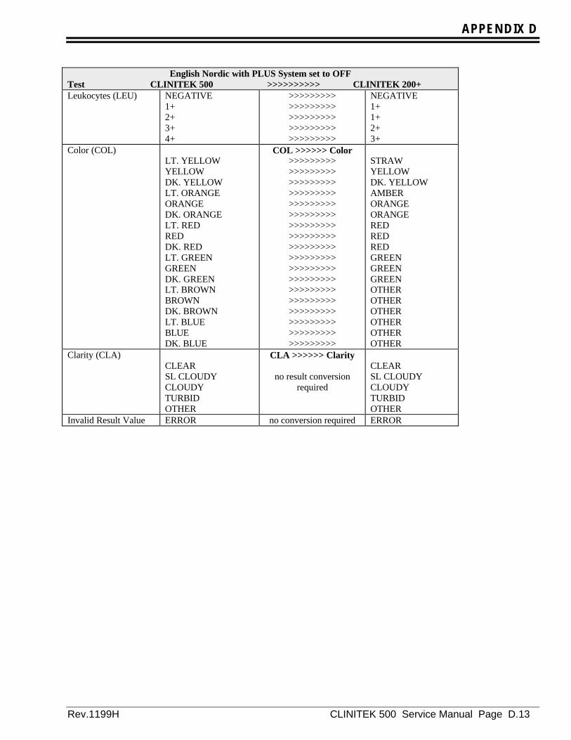
APPENDIX D
Rev.1199H CLINITEK 500 Service Manual Page D.13
English Nordic with PLUS System set to OFFTest CLINITEK 500 >>>>>>>>>> CLINITEK 200+Leukocytes (LEU) NEGATIVE
1+2+3+4+
>>>>>>>>>>>>>>>>>>>>>>>>>>>>>>>>>>>>>>>>>>>>>
NEGATIVE1+1+2+3+
Color (COL)LT. YELLOWYELLOWDK. YELLOWLT. ORANGEORANGEDK. ORANGELT. REDREDDK. REDLT. GREENGREENDK. GREENLT. BROWNBROWNDK. BROWNLT. BLUEBLUEDK. BLUE
COL >>>>>> Color>>>>>>>>>>>>>>>>>>>>>>>>>>>>>>>>>>>>>>>>>>>>>>>>>>>>>>>>>>>>>>>>>>>>>>>>>>>>>>>>>>>>>>>>>>>>>>>>>>>>>>>>>>>>>>>>>>>>>>>>>>>>>>>>>>>>>>>>>>>>>>>>>>>>>>>>>>>>>>>>>>
STRAWYELLOWDK. YELLOWAMBERORANGEORANGEREDREDREDGREENGREENGREENOTHEROTHEROTHEROTHEROTHEROTHER
Clarity (CLA)CLEARSL CLOUDYCLOUDYTURBIDOTHER
CLA >>>>>> Clarity
no result conversionrequired
CLEARSL CLOUDYCLOUDYTURBIDOTHER
Invalid Result Value ERROR no conversion required ERROR

APPENDIX D
Page D.14 CLINITEK 500 Service Manual Rev. 1199H
Supports CLINITEK 200+ “For Finland” OptionEnglish Nordic with PLUS System set to ON
Test CLINITEK 500 >>>>>>>>>> CLINITEK 200+Glucose (GLU) NEGATIVE
TRACE1+2+3+
>>>>>>>>>>>>>>>>>>>>>>>>>>>>>>>>>>>>>>>>>>>>>
NEGATIVE1+2+2+3+
Bilirubin (BIL) NEGATIVE1+2+3+
no conversion required
NEGATIVE1+2+3+
Ketone (KET) NEGATIVETRACE1+2+3+
>>>>>>>>>>>>>>>>>>>>>>>>>>>>>>>>>>>>>>>>>>>>>
NEGATIVE1+1+2+3+
Specific Gravity (SG) <= 1.0051.0101.0151.0201.025>=1.030
no conversion required
<= 1.0051.0101.0151.0201.025>=1.030
Blood (BLD) NEGATIVE+/- INTACT+/-1+2+3+
>>>>>>>>>>>>>>>>>>>>>>>>>>>>>>>>>>>>>>>>>>>>>>>>>>>>>>
NEGATIVE1+1+1+2+3+
pH (pH) 5.05.56.06.57.07.58.08.5>=9.0
no conversion required
5.05.56.06.57.07.58.08.5>=9.0
Protein (PRO) NEGATIVETRACE1+2+3+
>>>>>>>>>>>>>>>>>>>>>>>>>>>>>>>>>>>>>>>>>>>>>
NEGATIVENEGATIVE1+2+3+
Urobilinogen (UBG) 3.2 umol/L16 umol/L33 umol/L66 umol/L>=131 umol/L
>>>>>>>>>>>>>>>>>>>>>>>>>>>>>>>>>>>>>>>>>>>>>
NORMALNORMAL1+2+3+
Nitrite (NIT) NEGATIVEPOSITIVE
no conversion required NEGATIVEPOSITIVE
Leukocytes (LEU) NEGATIVETRACE1+2+3+
>>>>>>>>>>>>>>>>>>>>>>>>>>>>>>>>>>>>>>>>>>>>>
NEGATIVE1+1+2+3+

APPENDIX D
Rev.1199H CLINITEK 500 Service Manual Page D.15
English Nordic with PLUS System set to ONTest CLINITEK 500 >>>>>>>>>> CLINITEK 200+Color (COL)
LT. YELLOWYELLOWDK. YELLOWLT. ORANGEORANGEDK. ORANGELT. REDREDDK. REDLT. GREENGREENDK. GREENLT. BROWNBROWNDK. BROWNLT. BLUEBLUEDK. BLUE
COL >>>>>> Color>>>>>>>>>>>>>>>>>>>>>>>>>>>>>>>>>>>>>>>>>>>>>>>>>>>>>>>>>>>>>>>>>>>>>>>>>>>>>>>>>>>>>>>>>>>>>>>>>>>>>>>>>>>>>>>>>>>>>>>>>>>>>>>>>>>>>>>>>>>>>>>>>>>>>>>>>>>>>>>>>>
STRAWYELLOWDK. YELLOWAMBERORANGEORANGEREDREDREDGREENGREENGREENOTHEROTHEROTHEROTHEROTHEROTHER
Clarity (CLA)CLEARSL CLOUDYCLOUDYTURBIDOTHER
CLA >>>>>> Clarity
no conversion requiredCLEARSL CLOUDYCLOUDYTURBIDOTHER
Invalid Result Value ERROR no conversion required ERROR
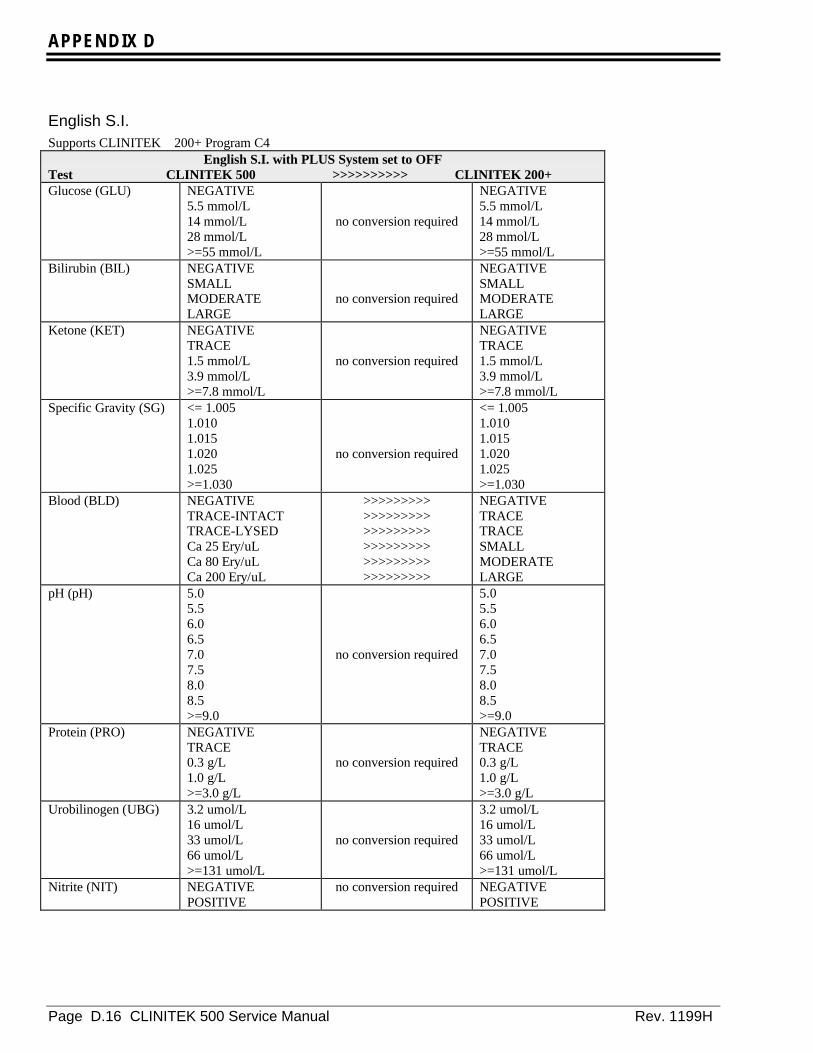
APPENDIX D
Page D.16 CLINITEK 500 Service Manual Rev. 1199H
English S.I.Supports CLINITEK 200+ Program C4
English S.I. with PLUS System set to OFFTest CLINITEK 500 >>>>>>>>>> CLINITEK 200+Glucose (GLU) NEGATIVE
5.5 mmol/L14 mmol/L28 mmol/L>=55 mmol/L
no conversion required
NEGATIVE5.5 mmol/L14 mmol/L28 mmol/L>=55 mmol/L
Bilirubin (BIL) NEGATIVESMALLMODERATELARGE
no conversion required
NEGATIVESMALLMODERATELARGE
Ketone (KET) NEGATIVETRACE1.5 mmol/L3.9 mmol/L>=7.8 mmol/L
no conversion required
NEGATIVETRACE1.5 mmol/L3.9 mmol/L>=7.8 mmol/L
Specific Gravity (SG) <= 1.0051.0101.0151.0201.025>=1.030
no conversion required
<= 1.0051.0101.0151.0201.025>=1.030
Blood (BLD) NEGATIVETRACE-INTACTTRACE-LYSEDCa 25 Ery/uLCa 80 Ery/uLCa 200 Ery/uL
>>>>>>>>>>>>>>>>>>>>>>>>>>>>>>>>>>>>>>>>>>>>>>>>>>>>>>
NEGATIVETRACETRACESMALLMODERATELARGE
pH (pH) 5.05.56.06.57.07.58.08.5>=9.0
no conversion required
5.05.56.06.57.07.58.08.5>=9.0
Protein (PRO) NEGATIVETRACE0.3 g/L1.0 g/L>=3.0 g/L
no conversion required
NEGATIVETRACE0.3 g/L1.0 g/L>=3.0 g/L
Urobilinogen (UBG) 3.2 umol/L16 umol/L33 umol/L66 umol/L>=131 umol/L
no conversion required
3.2 umol/L16 umol/L33 umol/L66 umol/L>=131 umol/L
Nitrite (NIT) NEGATIVEPOSITIVE
no conversion required NEGATIVEPOSITIVE
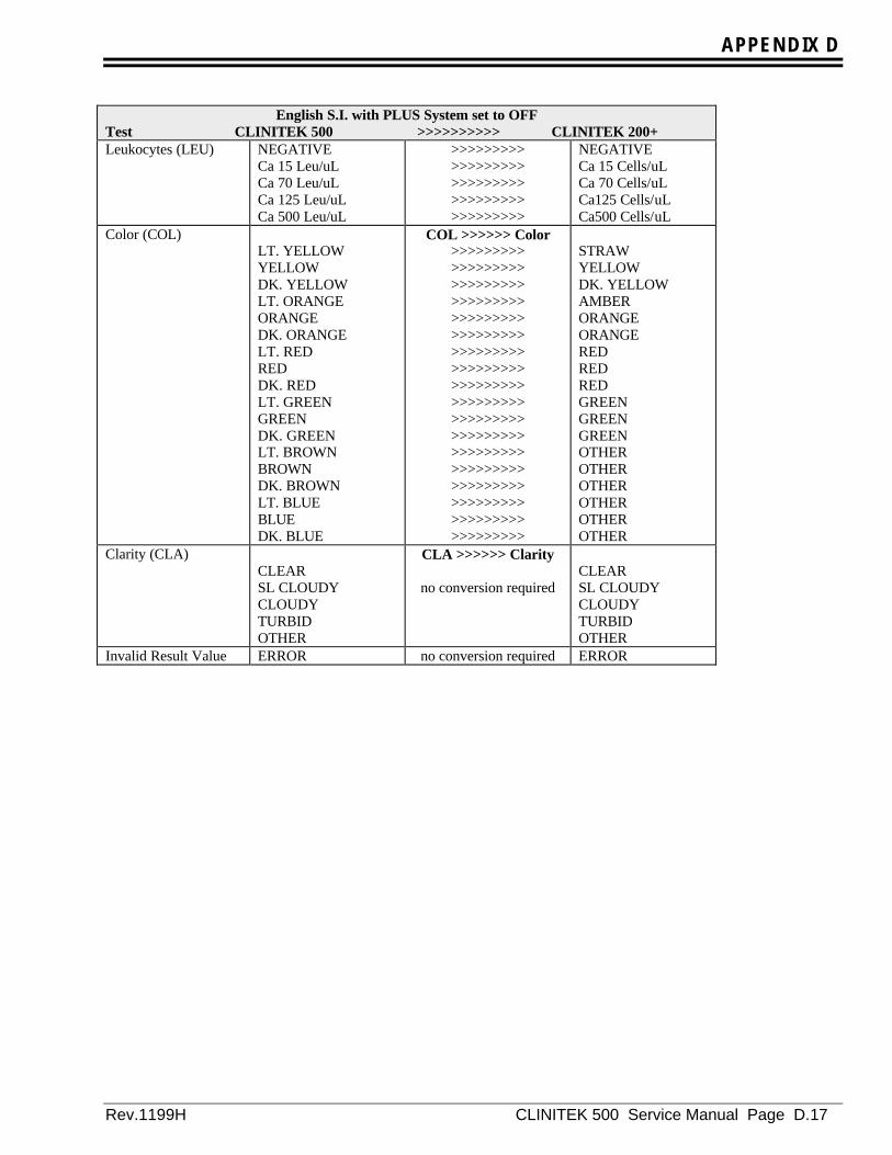
APPENDIX D
Rev.1199H CLINITEK 500 Service Manual Page D.17
English S.I. with PLUS System set to OFFTest CLINITEK 500 >>>>>>>>>> CLINITEK 200+Leukocytes (LEU) NEGATIVE
Ca 15 Leu/uLCa 70 Leu/uLCa 125 Leu/uLCa 500 Leu/uL
>>>>>>>>>>>>>>>>>>>>>>>>>>>>>>>>>>>>>>>>>>>>>
NEGATIVECa 15 Cells/uLCa 70 Cells/uLCa125 Cells/uLCa500 Cells/uL
Color (COL)LT. YELLOWYELLOWDK. YELLOWLT. ORANGEORANGEDK. ORANGELT. REDREDDK. REDLT. GREENGREENDK. GREENLT. BROWNBROWNDK. BROWNLT. BLUEBLUEDK. BLUE
COL >>>>>> Color>>>>>>>>>>>>>>>>>>>>>>>>>>>>>>>>>>>>>>>>>>>>>>>>>>>>>>>>>>>>>>>>>>>>>>>>>>>>>>>>>>>>>>>>>>>>>>>>>>>>>>>>>>>>>>>>>>>>>>>>>>>>>>>>>>>>>>>>>>>>>>>>>>>>>>>>>>>>>>>>>>
STRAWYELLOWDK. YELLOWAMBERORANGEORANGEREDREDREDGREENGREENGREENOTHEROTHEROTHEROTHEROTHEROTHER
Clarity (CLA)CLEARSL CLOUDYCLOUDYTURBIDOTHER
CLA >>>>>> Clarity
no conversion requiredCLEARSL CLOUDYCLOUDYTURBIDOTHER
Invalid Result Value ERROR no conversion required ERROR

APPENDIX D
Page D.18 CLINITEK 500 Service Manual Rev. 1199H
Supports CLINITEK 200+ Program C4English S.I. with PLUS System set to ON
Test CLINITEK 500 >>>>>>>>>> CLINITEK 200+Glucose (GLU) NEGATIVE
TRACE1+2+3+
no conversion required
NEGATIVETRACE1+2+3+
Bilirubin (BIL) NEGATIVE1+2+3+
no conversion required
NEGATIVE1+2+3+
Ketone (KET) NEGATIVETRACE1+2+3+
no conversion required
NEGATIVETRACE1+2+3+
Specific Gravity (SG) <= 1.0051.0101.0151.0201.025>=1.030
no conversion required
<= 1.0051.0101.0151.0201.025>=1.030
Blood (BLD) NEGATIVETRACE-INTACTTRACE-LYSED1+2+3+
>>>>>>>>>>>>>>>>>>>>>>>>>>>>>>>>>>>>>>>>>>>>>>>>>>>>>>
NEGATIVETRACETRACE1+2+3+
pH (pH) 5.05.56.06.57.07.58.08.5>=9.0
no conversion required
5.05.56.06.57.07.58.08.5>=9.0
Protein (PRO) NEGATIVETRACE1+2+3+
no conversion required
NEGATIVETRACE1+2+3+
Urobilinogen (UBG) 3.2 umol/L16 umol/L33 umol/L66 umol/L>=131 umol/L
no conversion required
3.2 umol/L16 umol/L33 umol/L66 umol/L>=131 umol/L
Nitrite (NIT) NEGATIVEPOSITIVE
no conversion required NEGATIVEPOSITIVE
Leukocytes (LEU) NEGATIVETRACE1+2+3+
no conversion required
NEGATIVETRACE1+2+3+

APPENDIX D
Rev.1199H CLINITEK 500 Service Manual Page D.19
English S.I. with PLUS System set to ONTest CLINITEK 500 >>>>>>>>>> CLINITEK 200+Color (COL)
LT. YELLOWYELLOWDK. YELLOWLT. ORANGEORANGEDK. ORANGELT. REDREDDK. REDLT. GREENGREENDK. GREENLT. BROWNBROWNDK. BROWNLT. BLUEBLUEDK. BLUE
COL >>>>>> Color>>>>>>>>>>>>>>>>>>>>>>>>>>>>>>>>>>>>>>>>>>>>>>>>>>>>>>>>>>>>>>>>>>>>>>>>>>>>>>>>>>>>>>>>>>>>>>>>>>>>>>>>>>>>>>>>>>>>>>>>>>>>>>>>>>>>>>>>>>>>>>>>>>>>>>>>>>>>>>>>>>
STRAWYELLOWDK. YELLOWAMBERORANGEORANGEREDREDREDGREENGREENGREENOTHEROTHEROTHEROTHEROTHEROTHER
Clarity (CLA)CLEARSL CLOUDYCLOUDYTURBIDOTHER
CLA >>>>>> Clarity
no conversion requiredCLEARSL CLOUDYCLOUDYTURBIDOTHER
Invalid Result Value ERROR no conversion required ERROR

APPENDIX D
Page D.20 CLINITEK 500 Service Manual Rev. 1199H
French ConventionalSupports CLINITEK 200+ Program G4
French Conventional with PLUS System set to OFFTest CLINITEK 500 >>>>>>>>>> CLINITEK 200+Glucose (GLU) NEGATIF
TRACES2.5 g/L5.0 g/L>=10.0 g/L
>>>>>>>>>>>>>>>>>>>>>>>>>>>>>>>>>>>>>>>>>>>>>
NEGATIF1.0 g/L2.5 g/L5.0 g/L>=10.0 g/L
Bilirubin (BIL) NEGATIFFAIBLEMOYENFORT
no conversion required
NEGATIFFAIBLEMOYENFORT
Ketone (CET) NEGATIFTRACES0.15 g/L0.4 g/L>=0.8 g/L
no conversion required
NEGATIFTRACES0.15 g/L0.4 g/L>=0.8 g/L
Specific Gravity(DEN)
<= 1.0051.0101.0151.0201.025>=1.030
no conversion required
<= 1.0051.0101.0151.0201.025>=1.030
Blood (SNG) NEGATIFTRACES-INTACTTRACES-LYSEenv. 25 GR/uLenv. 80 GR/uLenv. 200 GR/uL
>>>>>>>>>>>>>>>>>>>>>>>>>>>>>>>>>>>>>>>>>>>>>>>>>>>>>>
NEGATIFenv. 10 GR/uLenv. 10 GR/uLenv. 25 GR/uLenv. 80 GR/uLenv. 200 GR/uL
pH (pH) 5.05.56.06.57.07.58.08.5>=9.0
no conversion required
5.05.56.06.57.07.58.08.5>=9.0
Protein (PRO) NEGATIFTRACES0.3 g/L1.0 g/L>=3.0 g/L
no conversion required
NEGATIFTRACES0.3 g/L1.0 g/L>=3.0 g/L
Urobilinogen (URO) 0.2 mg/dL1.0 mg/dL2.0 mg/dL4.0 mg/dL>=8.0 mg/dL
no conversion required
0.2 mg/dL1.0 mg/dL2.0 mg/dL4.0 mg/dL>=8.0 mg/dL
Nitrite (NIT) NEGATIFPOSITIF
no conversion required NEGATIFPOSITIF

APPENDIX D
Rev.1199H CLINITEK 500 Service Manual Page D.21
French Conventional with PLUS System set to OFFTest CLINITEK 500 >>>>>>>>>> CLINITEK 200+Leukocytes (LEU) NEGATIF
env. 15 GB/uLenv. 70 GB/uLenv. 125 GB/uLenv. 500 GB/uL
no conversion required
NEGATIFenv. 15 GB/uLenv. 70 GB/uLenv. 125 GB/uLenv. 500 GB/uL
Color (COL)JAUNE CLR.JAUNEJAUNE FONC.ORANGE CLR.ORANGEORANGE FONC.ROUGE CLR.ROUGEROUGE FONC.VERT CLR.VERTVERT FONC.BLEU CLR.BLEUBLEU FONC.MARRON CLR.MARRONMARRON FONC.
COL >>>>>> COULEUR>>>>>>>>>>>>>>>>>>>>>>>>>>>>>>>>>>>>>>>>>>>>>>>>>>>>>>>>>>>>>>>>>>>>>>>>>>>>>>>>>>>>>>>>>>>>>>>>>>>>>>>>>>>>>>>>>>>>>>>>>>>>>>>>>>>>>>>>>>>>>>>>>>>>>>>>>>>>>>>>>>
PAILLEJAUNEJAUN FONCEAMBREORANGEORANGEROUGEROUGEROUGEVERTVERTVERTAUTREAUTREAUTREAUTREAUTREAUTRE
Clarity (ASP)LIMPIDELEG TROUBTROUBLEOPAQUEAUTRE
ASP >>>>>> ASPECT
no conversion requiredLIMPIDELEG TROUBTROUBLEOPAQUEAUTRE
Invalid Result Value ERREUR no conversion required ERREUR

APPENDIX D
Page D.22 CLINITEK 500 Service Manual Rev. 1199H
Supports CLINITEK 200+ Program G40100French Conventional with PLUS System set to ON
Test CLINITEK 500 >>>>>>>>>> CLINITEK 200+Glucose (GLU) NEGATIF
TRACES1+2+3+
no conversion required
NEGATIFTRACES1+2+3+
Bilirubin (BIL) NEGATIF1+2+3+
no conversion required
NEGATIF1+2+3+
Ketone (CET) NEGATIFTRACES1+2+3+
no conversion required
NEGATIFTRACES1+2+3+
Specific Gravity(DEN)
<= 1.0051.0101.0151.0201.025>=1.030
no conversion required
<= 1.0051.0101.0151.0201.025>=1.030
Blood (SNG) NEGATIFTRACES-INTACTTRACES-LYSE1+2+3+
>>>>>>>>>>>>>>>>>>>>>>>>>>>>>>>>>>>>>>>>>>>>>>>>>>>>>>
NEGATIFTRACESTRACES1+2+3+
pH (pH) 5.05.56.06.57.07.58.08.5>=9.0
no conversion required
5.05.56.06.57.07.58.08.5>=9.0
Protein (PRO) NEGATIFTRACES1+2+3+
no conversion required
NEGATIFTRACES1+2+3+
Urobilinogen (URO) 0.2 mg/Dl1.0 mg/dL2.0 mg/dL4.0 mg/dL>=8.0mg/dL
no conversion required
0.2 mg/dL1.0 mg/dL2.0 mg/dL4.0 mg/dL>=8.0 mg/dL
Nitrite (NIT) NEGATIFPOSITIF
no conversion required NEGATIFPOSITIF
Leukocytes (LEU) NEGATIFTRACES1+2+3+
no conversion required
NEGATIFTRACES1+2+3+
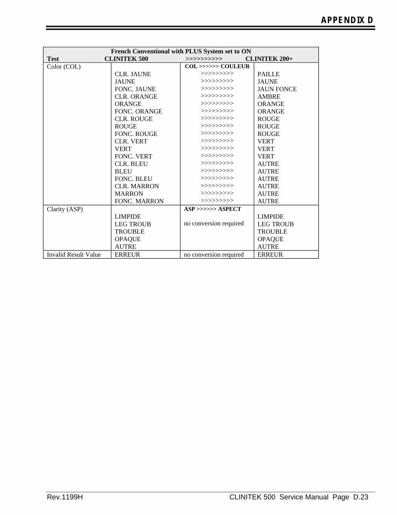
APPENDIX D
Rev.1199H CLINITEK 500 Service Manual Page D.23
French Conventional with PLUS System set to ONTest CLINITEK 500 >>>>>>>>>> CLINITEK 200+Color (COL)
CLR. JAUNEJAUNEFONC. JAUNECLR. ORANGEORANGEFONC. ORANGECLR. ROUGEROUGEFONC. ROUGECLR. VERTVERTFONC. VERTCLR. BLEUBLEUFONC. BLEUCLR. MARRONMARRONFONC. MARRON
COL >>>>>> COULEUR>>>>>>>>>>>>>>>>>>>>>>>>>>>>>>>>>>>>>>>>>>>>>>>>>>>>>>>>>>>>>>>>>>>>>>>>>>>>>>>>>>>>>>>>>>>>>>>>>>>>>>>>>>>>>>>>>>>>>>>>>>>>>>>>>>>>>>>>>>>>>>>>>>>>>>>>>>>>>>>>>>
PAILLEJAUNEJAUN FONCEAMBREORANGEORANGEROUGEROUGEROUGEVERTVERTVERTAUTREAUTREAUTREAUTREAUTREAUTRE
Clarity (ASP)LIMPIDELEG TROUBTROUBLEOPAQUEAUTRE
ASP >>>>>> ASPECT
no conversion requiredLIMPIDELEG TROUBTROUBLEOPAQUEAUTRE
Invalid Result Value ERREUR no conversion required ERREUR

APPENDIX D
Page D.24 CLINITEK 500 Service Manual Rev. 1199H
French S.I.Support for CLINITEK 200+ Program H4
French S.I. with PLUS system set to OFFTest CLINITEK 500 >>>>>>>>>> CLINITEK 200+Glucose (GLU) NEGATIF
5.5 mmol/L14 mmol/L28 mmol/L>=55 mmol/L
no conversion required
NEGATIF5.5 mmol/L14 mmol/L28 mmol/L>=55 mmol/L
Bilirubin (BIL) NEGATIFFAIBLEMOYENFORT
no conversion required
NEGATIFFAIBLEMOYENFORT
Ketone (CET) NEGATIFTRACES1.5 mmol/L3.9 mmol/L>=7.8 mmol/L
>>>>>>>>>>>>>>>>>>>>>>>>>>>>>>>>>>>>>>>>>>>>>
NEGATIFTRACE1.5 mmol/L3.9 mmol/L>=7.8 mmol/L
Specific Gravity(DEN)
<= 1.0051.0101.0151.0201.025>=1.030
no conversion required
<= 1.0051.0101.0151.0201.025>=1.030
Blood (SNG) NEGATIFTRACES-INTACTTRACES-LYSEDFAIBLEMOYENFORT
>>>>>>>>>>>>>>>>>>>>>>>>>>>>>>>>>>>>>>>>>>>>>>>>>>>>>>
NEGATIFTRACETRACEFAIBLEMOYENFORT
pH (pH) 5.05.56.06.57.07.58.08.5>=9.0
no conversion required
5.05.56.06.57.07.58.08.5>=9.0
Protein (PRO) NEGATIFTRACES0.3 g/L1.0 g/L>=3.0 g/L
>>>>>>>>>>>>>>>>>>>>>>>>>>>>>>>>>>>>>>>>>>>>>
NEGATIFTRACE0.3 g/L1.0 g/L>=3.0 g/L
Urobilinogen (URO) 3.2 umol/L16 umol/L33 umol/L66 umol/L>=131 umol/L
no conversion required
3.2 umol/L16 umol/L33 umol/L66 umol/L>=131 umol/L
Nitrite (NIT) NEGATIFPOSITIF
no conversion required NEGATIFPOSITIF

APPENDIX D
Rev.1199H CLINITEK 500 Service Manual Page D.25
French S.I. with PLUS system set to OFFTest CLINITEK 500 >>>>>>>>>> CLINITEK 200+Leukocytes (LEU) NEGATIF
TRACESFAIBLEMOYENFORT
>>>>>>>>>>>>>>>>>>>>>>>>>>>>>>>>>>>>>>>>>>>>>
NEGATIFTRACEFAIBLEMOYENFORT
Color (COL)CLR. JAUNEJAUNEFONC. JAUNECLR. ORANGEORANGEFONC. ORANGECLR. ROUGEROUGEFONC. ROUGECLR. VERTVERTFONC. VERTCLR. BLEUBLEUFONC. BLEUCLR. MARRONMARRONFONC. MARRON
COL >>>>>> COULEUR>>>>>>>>>>>>>>>>>>>>>>>>>>>>>>>>>>>>>>>>>>>>>>>>>>>>>>>>>>>>>>>>>>>>>>>>>>>>>>>>>>>>>>>>>>>>>>>>>>>>>>>>>>>>>>>>>>>>>>>>>>>>>>>>>>>>>>>>>>>>>>>>>>>>>>>>>>>>>>>>>>
PAILLEJAUNEJAUN FONCEAMBREORANGEORANGEROUGEROUGEROUGEVERTVERTVERTAUTREAUTREAUTREAUTREAUTREAUTRE
Clarity (ASP)LIMPIDELEG TROUBTROUBLEOPAQUEAUTRE
ASP>>>>>> ASPECT
no conversion requiredLIMPIDELEG TROUBTROUBLEOPAQUEAUTRE
Invalid Result Value ERREUR no conversion required ERREUR

APPENDIX D
Page D.26 CLINITEK 500 Service Manual Rev. 1199H
Support for CLINITEK 200+ Program H4French S.I. with PLUS System set to ON
Test CLINITEK 500 >>>>>>>>>> CLINITEK 200+Glucose (GLU) NEGATIF
TRACES1+2+3+
>>>>>>>>>>>>>>>>>>>>>>>>>>>>>>>>>>>>>>>>>>>>>
NEGATIFTRACE1+2+3+
Bilirubin (BIL) NEGATIF1+2+3+
no conversion required
NEGATIF1+2+3+
Ketone (CET) NEGATIFTRACES1+2+3+
>>>>>>>>>>>>>>>>>>>>>>>>>>>>>>>>>>>>>>>>>>>>>
NEGATIFTRACE1+2+3+
Specific Gravity(DEN)
<= 1.0051.0101.0151.0201.025>=1.030
no conversion required
<= 1.0051.0101.0151.0201.025>=1.030
Blood (SNG) NEGATIFTRACES-INTACTTRACES-LYSED1+2+3+
>>>>>>>>>>>>>>>>>>>>>>>>>>>>>>>>>>>>>>>>>>>>>>>>>>>>>>
NEGATIFTRACETRACE1+2+3+
pH (pH) 5.05.56.06.57.07.58.08.5>=9.0
no conversion required
5.05.56.06.57.07.58.08.5>=9.0
Protein (PRO) NEGATIFTRACES1+2+3+
>>>>>>>>>>>>>>>>>>>>>>>>>>>>>>>>>>>>>>>>>>>>>
NEGATIFTRACE1+2+3+
Urobilinogen (URO) 3.2 umol/L16 umol/L33 umol/L66 umol/L>=131 umol/L
no conversion required
3.2 umol/L16 umol/L33 umol/L66 umol/L>=131 umol/L
Nitrite (NIT) NEGATIFPOSITIF
no conversion required NEGATIFPOSITIF
Leukocytes (LEU) NEGATIFTRACES1+2+3+
>>>>>>>>>>>>>>>>>>>>>>>>>>>>>>>>>>>>>>>>>>>>>
NEGATIFTRACE1+2+3+
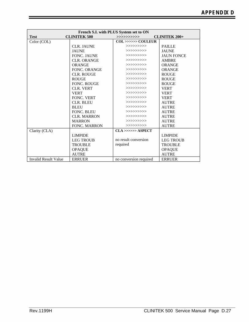
APPENDIX D
Rev.1199H CLINITEK 500 Service Manual Page D.27
French S.I. with PLUS System set to ONTest CLINITEK 500 >>>>>>>>>> CLINITEK 200+Color (COL)
CLR. JAUNEJAUNEFONC. JAUNECLR. ORANGEORANGEFONC. ORANGECLR. ROUGEROUGEFONC. ROUGECLR. VERTVERTFONC. VERTCLR. BLEUBLEUFONC. BLEUCLR. MARRONMARRONFONC. MARRON
COL >>>>>> COULEUR>>>>>>>>>>>>>>>>>>>>>>>>>>>>>>>>>>>>>>>>>>>>>>>>>>>>>>>>>>>>>>>>>>>>>>>>>>>>>>>>>>>>>>>>>>>>>>>>>>>>>>>>>>>>>>>>>>>>>>>>>>>>>>>>>>>>>>>>>>>>>>>>>>>>>>>>>>>>>>>>>>
PAILLEJAUNEJAUN FONCEAMBREORANGEORANGEROUGEROUGEROUGEVERTVERTVERTAUTREAUTREAUTREAUTREAUTREAUTRE
Clarity (CLA)LIMPIDELEG TROUBTROUBLEOPAQUEAUTRE
CLA >>>>>> ASPECT
no result conversionrequired
LIMPIDELEG TROUBTROUBLEOPAQUEAUTRE
Invalid Result Value ERRUER no conversion required ERRUER
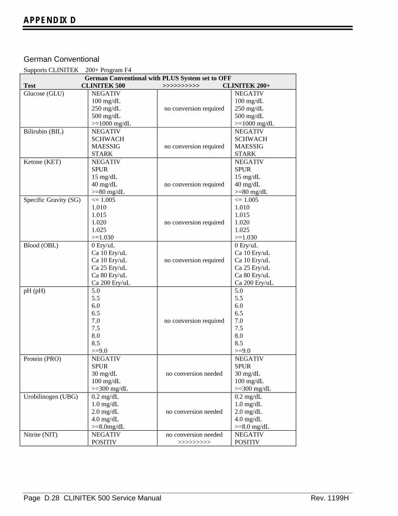
APPENDIX D
Page D.28 CLINITEK 500 Service Manual Rev. 1199H
German ConventionalSupports CLINITEK 200+ Program F4
German Conventional with PLUS System set to OFFTest CLINITEK 500 >>>>>>>>>> CLINITEK 200+Glucose (GLU) NEGATIV
100 mg/dL250 mg/dL500 mg/dL>=1000 mg/dL
no conversion required
NEGATIV100 mg/dL250 mg/dL500 mg/dL>=1000 mg/dL
Bilirubin (BIL) NEGATIVSCHWACHMAESSIGSTARK
no conversion required
NEGATIVSCHWACHMAESSIGSTARK
Ketone (KET) NEGATIVSPUR15 mg/dL40 mg/dL>=80 mg/dL
no conversion required
NEGATIVSPUR15 mg/dL40 mg/dL>=80 mg/dL
Specific Gravity (SG) <= 1.0051.0101.0151.0201.025>=1.030
no conversion required
<= 1.0051.0101.0151.0201.025>=1.030
Blood (OBL) 0 Ery/uLCa 10 Ery/uLCa 10 Ery/uLCa 25 Ery/uLCa 80 Ery/uLCa 200 Ery/uL
no conversion required
0 Ery/uLCa 10 Ery/uLCa 10 Ery/uLCa 25 Ery/uLCa 80 Ery/uLCa 200 Ery/uL
pH (pH) 5.05.56.06.57.07.58.08.5>=9.0
no conversion required
5.05.56.06.57.07.58.08.5>=9.0
Protein (PRO) NEGATIVSPUR30 mg/dL100 mg/dL>=300 mg/dL
no conversion needed
NEGATIVSPUR30 mg/dL100 mg/dL>=300 mg/dL
Urobilinogen (UBG) 0.2 mg/dL1.0 mg/dL2.0 mg/dL4.0 mg/dL>=8.0mg/dL
no conversion needed
0.2 mg/dL1.0 mg/dL2.0 mg/dL4.0 mg/dL>=8.0 mg/dL
Nitrite (NIT) NEGATIVPOSITIV
no conversion needed>>>>>>>>>
NEGATIVPOSITIV
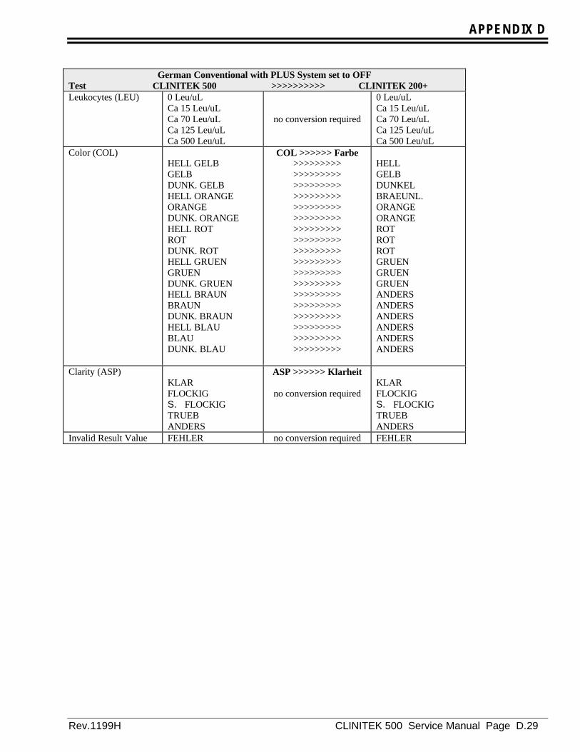
APPENDIX D
Rev.1199H CLINITEK 500 Service Manual Page D.29
German Conventional with PLUS System set to OFFTest CLINITEK 500 >>>>>>>>>> CLINITEK 200+Leukocytes (LEU) 0 Leu/uL
Ca 15 Leu/uLCa 70 Leu/uLCa 125 Leu/uLCa 500 Leu/uL
no conversion required
0 Leu/uLCa 15 Leu/uLCa 70 Leu/uLCa 125 Leu/uLCa 500 Leu/uL
Color (COL)HELL GELBGELBDUNK. GELBHELL ORANGEORANGEDUNK. ORANGEHELL ROTROTDUNK. ROTHELL GRUENGRUENDUNK. GRUENHELL BRAUNBRAUNDUNK. BRAUNHELL BLAUBLAUDUNK. BLAU
COL >>>>>> Farbe>>>>>>>>>>>>>>>>>>>>>>>>>>>>>>>>>>>>>>>>>>>>>>>>>>>>>>>>>>>>>>>>>>>>>>>>>>>>>>>>>>>>>>>>>>>>>>>>>>>>>>>>>>>>>>>>>>>>>>>>>>>>>>>>>>>>>>>>>>>>>>>>>>>>>>>>>>>>>>>>>>
HELLGELBDUNKELBRAEUNL.ORANGEORANGEROTROTROTGRUENGRUENGRUENANDERSANDERSANDERSANDERSANDERSANDERS
Clarity (ASP)KLARFLOCKIGS. FLOCKIGTRUEBANDERS
ASP >>>>>> Klarheit
no conversion requiredKLARFLOCKIGS. FLOCKIGTRUEBANDERS
Invalid Result Value FEHLER no conversion required FEHLER

APPENDIX D
Page D.30 CLINITEK 500 Service Manual Rev. 1199H
Supports CLINITEK 200+ Program F4German Conventional with PLUS System set to ON
Test CLINITEK 500 >>>>>>>>>> CLINITEK 200+Glucose (GLU) NEGATIV
SPUR1+2+3+
no conversion required
NEGATIVSPUR1+2+3+
Bilirubin (BIL) NEGATIV1+2+3+
no conversion required
NEGATIV1+2+3+
Ketone (KET) NEGATIVSPUR1+2+3+
no conversion required
NEGATIVSPUR1+2+3+
Specific Gravity (SG) <= 1.0051.0101.0151.0201.025>=1.030
no conversion required
<= 1.0051.0101.0151.0201.025>=1.030
Blood (OBL) NEGATIVSPUR-ZELLENSPUR-LYSE1+2+3+
>>>>>>>>>>>>>>>>>>>>>>>>>>>>>>>>>>>>>>>>>>>>>>>>>>>>>>
NEGATIVSPURSPUR1+2+3+
pH (pH) 5.05.56.06.57.07.58.08.5>=9.0
no conversion required
5.05.56.06.57.07.58.08.5>=9.0
Protein (PRO) NEGATIVSPUR1+2+3+
no conversion required
NEGATIVSPUR1+2+3+
Urobilinogen (UBG) 0.2 mg/dL1.0 mg/dL2.0 mg/dL4.0 mg/dL>=8.0mg/dL
no conversion required
0.2 mg/dL1.0 mg/dL2.0 mg/dL4.0 mg/dL>=8.0mg/dL
Nitrite (NIT) NEGATIVPOSITIV no conversion required
NEGATIVPOSITIV
Leukocytes (LEU) NEGATIVSPUR1+2+3+
no conversion required
NEGATIVESPUR1+2+3+
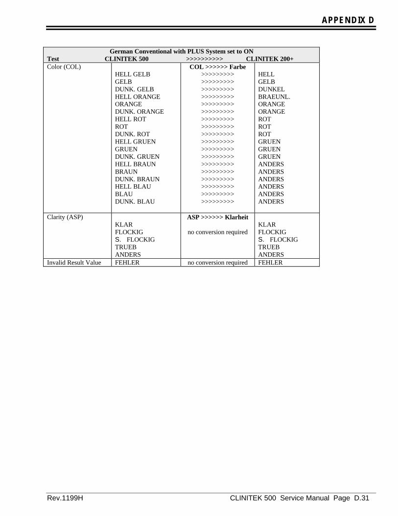
APPENDIX D
Rev.1199H CLINITEK 500 Service Manual Page D.31
German Conventional with PLUS System set to ONTest CLINITEK 500 >>>>>>>>>> CLINITEK 200+Color (COL)
HELL GELBGELBDUNK. GELBHELL ORANGEORANGEDUNK. ORANGEHELL ROTROTDUNK. ROTHELL GRUENGRUENDUNK. GRUENHELL BRAUNBRAUNDUNK. BRAUNHELL BLAUBLAUDUNK. BLAU
COL >>>>>> Farbe>>>>>>>>>>>>>>>>>>>>>>>>>>>>>>>>>>>>>>>>>>>>>>>>>>>>>>>>>>>>>>>>>>>>>>>>>>>>>>>>>>>>>>>>>>>>>>>>>>>>>>>>>>>>>>>>>>>>>>>>>>>>>>>>>>>>>>>>>>>>>>>>>>>>>>>>>>>>>>>>>>
HELLGELBDUNKELBRAEUNL.ORANGEORANGEROTROTROTGRUENGRUENGRUENANDERSANDERSANDERSANDERSANDERSANDERS
Clarity (ASP)KLARFLOCKIGS. FLOCKIGTRUEBANDERS
ASP >>>>>> Klarheit
no conversion requiredKLARFLOCKIGS. FLOCKIGTRUEBANDERS
Invalid Result Value FEHLER no conversion required FEHLER
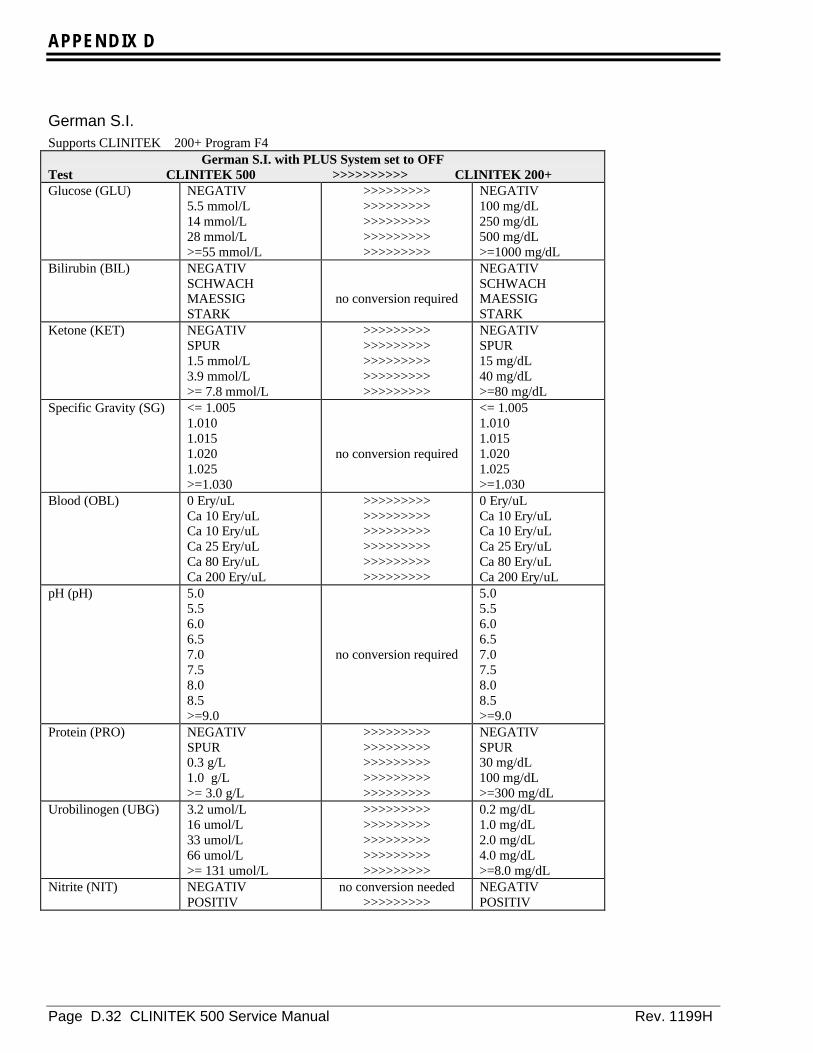
APPENDIX D
Page D.32 CLINITEK 500 Service Manual Rev. 1199H
German S.I.Supports CLINITEK 200+ Program F4
German S.I. with PLUS System set to OFFTest CLINITEK 500 >>>>>>>>>> CLINITEK 200+Glucose (GLU) NEGATIV
5.5 mmol/L14 mmol/L28 mmol/L>=55 mmol/L
>>>>>>>>>>>>>>>>>>>>>>>>>>>>>>>>>>>>>>>>>>>>>
NEGATIV100 mg/dL250 mg/dL500 mg/dL>=1000 mg/dL
Bilirubin (BIL) NEGATIVSCHWACHMAESSIGSTARK
no conversion required
NEGATIVSCHWACHMAESSIGSTARK
Ketone (KET) NEGATIVSPUR1.5 mmol/L3.9 mmol/L>= 7.8 mmol/L
>>>>>>>>>>>>>>>>>>>>>>>>>>>>>>>>>>>>>>>>>>>>>
NEGATIVSPUR15 mg/dL40 mg/dL>=80 mg/dL
Specific Gravity (SG) <= 1.0051.0101.0151.0201.025>=1.030
no conversion required
<= 1.0051.0101.0151.0201.025>=1.030
Blood (OBL) 0 Ery/uLCa 10 Ery/uLCa 10 Ery/uLCa 25 Ery/uLCa 80 Ery/uLCa 200 Ery/uL
>>>>>>>>>>>>>>>>>>>>>>>>>>>>>>>>>>>>>>>>>>>>>>>>>>>>>>
0 Ery/uLCa 10 Ery/uLCa 10 Ery/uLCa 25 Ery/uLCa 80 Ery/uLCa 200 Ery/uL
pH (pH) 5.05.56.06.57.07.58.08.5>=9.0
no conversion required
5.05.56.06.57.07.58.08.5>=9.0
Protein (PRO) NEGATIVSPUR0.3 g/L1.0 g/L>= 3.0 g/L
>>>>>>>>>>>>>>>>>>>>>>>>>>>>>>>>>>>>>>>>>>>>>
NEGATIVSPUR30 mg/dL100 mg/dL>=300 mg/dL
Urobilinogen (UBG) 3.2 umol/L16 umol/L33 umol/L66 umol/L>= 131 umol/L
>>>>>>>>>>>>>>>>>>>>>>>>>>>>>>>>>>>>>>>>>>>>>
0.2 mg/dL1.0 mg/dL2.0 mg/dL4.0 mg/dL>=8.0 mg/dL
Nitrite (NIT) NEGATIVPOSITIV
no conversion needed>>>>>>>>>
NEGATIVPOSITIV

APPENDIX D
Rev.1199H CLINITEK 500 Service Manual Page D.33
German S.I. with PLUS System set to OFFTest CLINITEK 500 >>>>>>>>>> CLINITEK 200+Leukocytes (LEU) 0 Leu/uL
Ca 15 Leu/uLCa 70 Leu/uLCa 125 Leu/uLCa 500 Leu/uL
no conversion required
0 Leu/uLCa 15 Leu/uLCa 70 Leu/uLCa 125 Leu/uLCa 500 Leu/uL
Color (COL)HELL GELBGELBDUNK. GELBHELL ORANGEORANGEDUNK. ORANGEHELL ROTROTDUNK. ROTHELL GRUENGRUENDUNK. GRUENHELL BRAUNBRAUNDUNK. BRAUNHELL BLAUBLAUDUNK. BLAU
COL >>>>>> Farbe>>>>>>>>>>>>>>>>>>>>>>>>>>>>>>>>>>>>>>>>>>>>>>>>>>>>>>>>>>>>>>>>>>>>>>>>>>>>>>>>>>>>>>>>>>>>>>>>>>>>>>>>>>>>>>>>>>>>>>>>>>>>>>>>>>>>>>>>>>>>>>>>>>>>>>>>>>>>>>>>>>
HELLGELBDUNKELBRAEUNL.ORANGEORANGEROTROTROTGRUENGRUENGRUENANDERSANDERSANDERSANDERSANDERSANDERS
Clarity (CLA)KLARFLOCKIGS. FLOCKIGTRUEBANDERS
CLA >>>>>> Klarheit
no conversion requiredKLARFLOCKIGS. FLOCKIGTRUEBANDERS
Invalid Result Value FEHLER no conversion required FEHLER
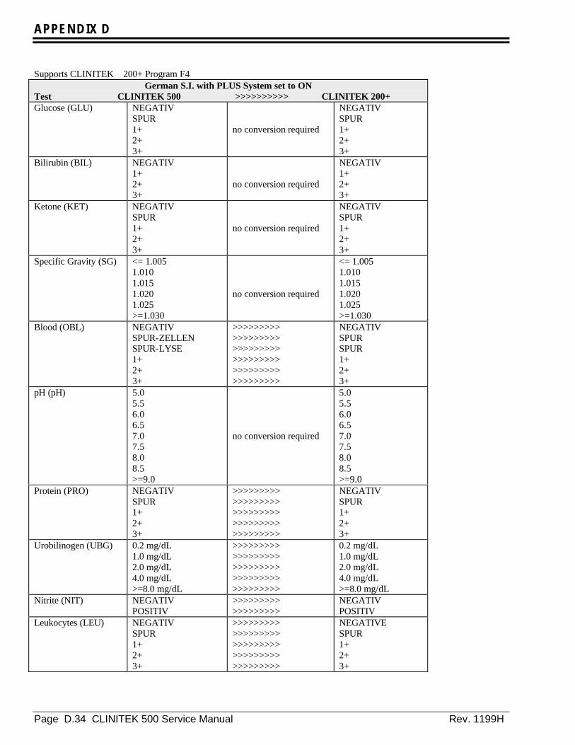
APPENDIX D
Page D.34 CLINITEK 500 Service Manual Rev. 1199H
Supports CLINITEK 200+ Program F4German S.I. with PLUS System set to ON
Test CLINITEK 500 >>>>>>>>>> CLINITEK 200+Glucose (GLU) NEGATIV
SPUR1+2+3+
no conversion required
NEGATIVSPUR1+2+3+
Bilirubin (BIL) NEGATIV1+2+3+
no conversion required
NEGATIV1+2+3+
Ketone (KET) NEGATIVSPUR1+2+3+
no conversion required
NEGATIVSPUR1+2+3+
Specific Gravity (SG) <= 1.0051.0101.0151.0201.025>=1.030
no conversion required
<= 1.0051.0101.0151.0201.025>=1.030
Blood (OBL) NEGATIVSPUR-ZELLENSPUR-LYSE1+2+3+
>>>>>>>>>>>>>>>>>>>>>>>>>>>>>>>>>>>>>>>>>>>>>>>>>>>>>>
NEGATIVSPURSPUR1+2+3+
pH (pH) 5.05.56.06.57.07.58.08.5>=9.0
no conversion required
5.05.56.06.57.07.58.08.5>=9.0
Protein (PRO) NEGATIVSPUR1+2+3+
>>>>>>>>>>>>>>>>>>>>>>>>>>>>>>>>>>>>>>>>>>>>>
NEGATIVSPUR1+2+3+
Urobilinogen (UBG) 0.2 mg/dL1.0 mg/dL2.0 mg/dL4.0 mg/dL>=8.0 mg/dL
>>>>>>>>>>>>>>>>>>>>>>>>>>>>>>>>>>>>>>>>>>>>>
0.2 mg/dL1.0 mg/dL2.0 mg/dL4.0 mg/dL>=8.0 mg/dL
Nitrite (NIT) NEGATIVPOSITIV
>>>>>>>>>>>>>>>>>>
NEGATIVPOSITIV
Leukocytes (LEU) NEGATIVSPUR1+2+3+
>>>>>>>>>>>>>>>>>>>>>>>>>>>>>>>>>>>>>>>>>>>>>
NEGATIVESPUR1+2+3+

APPENDIX D
Rev.1199H CLINITEK 500 Service Manual Page D.35
German S.I. with PLUS System set to ONTest CLINITEK 500 >>>>>>>>>> CLINITEK 200+Color (COL)
HELL GELBGELBDUNK. GELBHELL ORANGEORANGEDUNK. ORANGEHELL ROTROTDUNK. ROTHELL GRUENGRUENDUNK. GRUENHELL BRAUNBRAUNDUNK. BRAUNHELL BLAUBLAUDUNK. BLAU
COL >>>>>> Farbe>>>>>>>>>>>>>>>>>>>>>>>>>>>>>>>>>>>>>>>>>>>>>>>>>>>>>>>>>>>>>>>>>>>>>>>>>>>>>>>>>>>>>>>>>>>>>>>>>>>>>>>>>>>>>>>>>>>>>>>>>>>>>>>>>>>>>>>>>>>>>>>>>>>>>>>>>>>>>>>>>>
HELLGELBDUNKELBRAEUNL.ORANGEORANGEROTROTROTGRUENGRUENGRUENANDERSANDERSANDERSANDERSANDERSANDERS
Clarity (ASP)KLARFLOCKIGS. FLOCKIGTRUEBANDERS
ASP>>>>>> Klarheit
no conversion requiredKLARFLOCKIGS. FLOCKIGTRUEBANDERS
Invalid Result Value FEHLER no conversion required FEHLER

APPENDIX D
Page D.36 CLINITEK 500 Service Manual Rev. 1199H
ItalianSupports CLINITEK 200+ Program E4
Italian with PLUS System set to OFFTest CLINITEK 500 >>>>>>>>>> CLINITEK 200+Glucose (GLU) NEGATIVO
1.0 g/L2.5 g/L5.0 g/L>=10.0 g/L
>>>>>>>>>>>>>>>>>>>>>>>>>>>>>>>>>>>>>>>>>>>>>
NEGATIVO0.1 g/dL0.25 g/dL0.5 g/dL>=1.0 g/dL
Bilirubin (BIL) NEGATIVOLEGGEROMEDIOFORTE
no conversion required
NEGATIVOLEGGEROMEDIOFORTE
Ketone (KET) NEGATIVOTRACCE15 mg/dL40 mg/dL>=80 mg/dL
no conversion required
NEGATIVOTRACCE15 mg/dL40 mg/dL>=80 mg/dL
Specific Gravity (PS) <= 1.0051.0101.0151.0201.025>=1.030
no conversion required
<= 1.0051.0101.0151.0201.025>=1.030
Blood (SAN) NEGATIVOTRACCE(INT.)TRACCE(LIS.)LEGGEROMEDIOFORTE
>>>>>>>>>>>>>>>>>>>>>>>>>>>>>>>>>>>>>>>>>>>>>>>>>>>>>>
NEGATIVOTRACCETRACCELEGGEROMEDIOFORTE
pH (pH) 5.05.56.06.57.07.58.08.5>=9.0
no conversion required
5.05.56.06.57.07.58.08.5>=9.0
Protein (PRO) NEGATIVOTRACCE30 mg/dL100 mg/dL>=300 mg/dL
no conversion required
NEGATIVOTRACCE30 mg/dL100 mg/dL>=300 mg/dL
Urobilinogen (URO) 0.2 E.U./dL1.0 E.U./dL2.0 E.U./dL4.0 E.U./dL>=8.0 E.U./dL
no conversion required
0.2 E.U./dL1.0 E.U./dL2.0 E.U./dL4.0 E.U./dL>=8.0 E.U./dL
Nitrite (NIT) NEGATIVOPOSITIVO
no conversion required NEGATIVOPOSITIVO
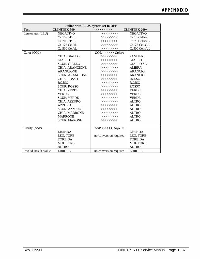
APPENDIX D
Rev.1199H CLINITEK 500 Service Manual Page D.37
Italian with PLUS System set to OFFTest CLINITEK 500 >>>>>>>>>> CLINITEK 200+Leukocytes (LEU) NEGATIVO
Ca 15 Cel/uLCa 70 Cel/uLCa 125 Cel/uLCa 500 Cel/uL
>>>>>>>>>>>>>>>>>>>>>>>>>>>>>>>>>>>>>>>>>>>>>
NEGATIVOCa 15 Cells/uLCa 70 Cells/uLCa125 Cells/uLCa500 Cells/uL
Color (COL)CHIA. GIALLOGIALLOSCUR. GIALLOCHIA. ARANCIONEARANCIONESCUR. ARANCIONECHIA. ROSSOROSSOSCUR. ROSSOCHIA. VERDEVERDESCUR. VERDECHIA. AZZUROAZZUROSCUR. AZZUROCHIA. MARRONEMARRONESCUR. MARONE
COL >>>>>> Colore>>>>>>>>>>>>>>>>>>>>>>>>>>>>>>>>>>>>>>>>>>>>>>>>>>>>>>>>>>>>>>>>>>>>>>>>>>>>>>>>>>>>>>>>>>>>>>>>>>>>>>>>>>>>>>>>>>>>>>>>>>>>>>>>>>>>>>>>>>>>>>>>>>>>>>>>>>>>>>>>>>
PAGLIER.GIALLOGIALLO SC.AMBRAARANCIOARANCIOROSSOROSSOROSSOVERDEVERDEVERDEALTROALTROALTROALTROALTROALTRO
Clarity (ASP)LIMPIDALEG. TORBTORBIDAMOL.TORBALTRO
ASP >>>>>> Aspetto
no conversion requiredLIMPIDALEG. TORBTORBIDAMOL.TORBALTRO
Invalid Result Value ERRORE no conversion required ERRORE
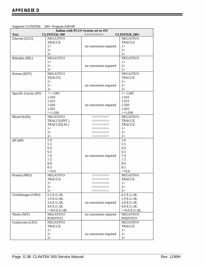
APPENDIX D
Page D.38 CLINITEK 500 Service Manual Rev. 1199H
Supports CLINITEK 200+ Program E40100Italian with PLUS System set to ON
Test CLINITEK 500 >>>>>>>>>> CLINITEK 200+Glucose (GLU) NEGATIVO
TRACCE1+2+3+
no conversion required
NEGATIVOTRACCE1+2+3+
Bilirubin (BIL) NEGATIVO1+2+3+
no conversion required
NEGATIVO1+2+3+
Ketone (KET) NEGATIVOTRACCE1+2+3+
no conversion required
NEGATIVOTRACCE1+2+3+
Specific Gravity (PS) <= 1.0051.0101.0151.0201.025>=1.030
no conversion required
<= 1.0051.0101.0151.0201.025>=1.030
Blood (SAN) NEGATIVOTRACCE(INT.)TRACCE(LIS.)1+2+3+
>>>>>>>>>>>>>>>>>>>>>>>>>>>>>>>>>>>>>>>>>>>>>>>>>>>>>>
NEGATIVOTRACCETRACCE1+2+3+
pH (pH) 5.05.56.06.57.07.58.08.5>=9.0
no conversion required
5.05.56.06.57.07.58.08.5>=9.0
Protein (PRO) NEGATIVOTRACCE1+2+3+
>>>>>>>>>>>>>>>>>>>>>>>>>>>>>>>>>>>>>>>>>>>>>
NEGATIVOTRACCE1+2+3+
Urobilinogen (URO) 0.2 E.U./dL1.0 E.U./dL2.0 E.U./dL4.0 E.U./dL>=8.0 E.U./dL
no conversion required
0.2 E.U./dL1.0 E.U./dL2.0 E.U./dL4.0 E.U./dL>=8.0 E.U./dL
Nitrite (NIT) NEGATIVOPOSITIVO
no conversion required NEGATIVOPOSITIVO
Leukocytes (LEU) NEGATIVOTRACCE1+2+3+
no conversion required
NEGATIVOTRACCE1+2+3+
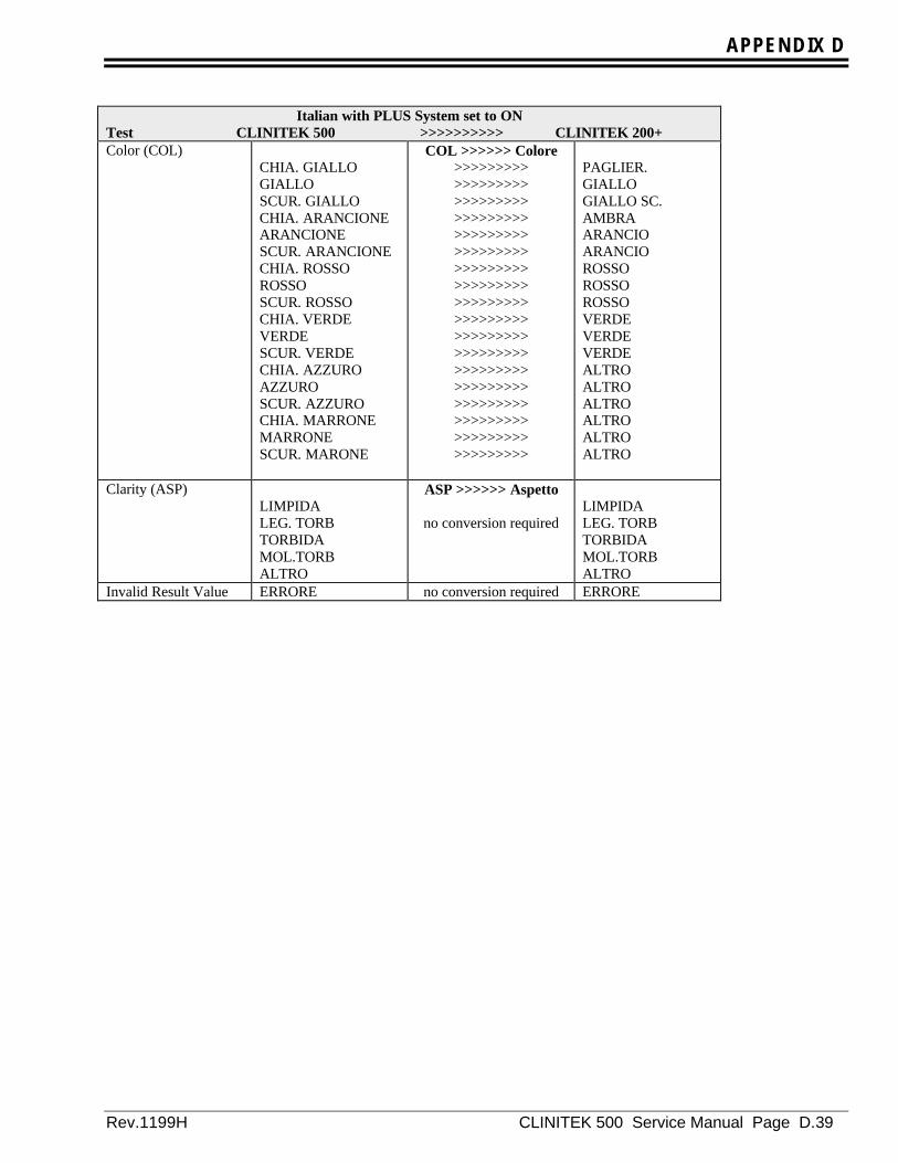
APPENDIX D
Rev.1199H CLINITEK 500 Service Manual Page D.39
Italian with PLUS System set to ONTest CLINITEK 500 >>>>>>>>>> CLINITEK 200+Color (COL)
CHIA. GIALLOGIALLOSCUR. GIALLOCHIA. ARANCIONEARANCIONESCUR. ARANCIONECHIA. ROSSOROSSOSCUR. ROSSOCHIA. VERDEVERDESCUR. VERDECHIA. AZZUROAZZUROSCUR. AZZUROCHIA. MARRONEMARRONESCUR. MARONE
COL >>>>>> Colore>>>>>>>>>>>>>>>>>>>>>>>>>>>>>>>>>>>>>>>>>>>>>>>>>>>>>>>>>>>>>>>>>>>>>>>>>>>>>>>>>>>>>>>>>>>>>>>>>>>>>>>>>>>>>>>>>>>>>>>>>>>>>>>>>>>>>>>>>>>>>>>>>>>>>>>>>>>>>>>>>>
PAGLIER.GIALLOGIALLO SC.AMBRAARANCIOARANCIOROSSOROSSOROSSOVERDEVERDEVERDEALTROALTROALTROALTROALTROALTRO
Clarity (ASP)LIMPIDALEG. TORBTORBIDAMOL.TORBALTRO
ASP >>>>>> Aspetto
no conversion requiredLIMPIDALEG. TORBTORBIDAMOL.TORBALTRO
Invalid Result Value ERRORE no conversion required ERRORE
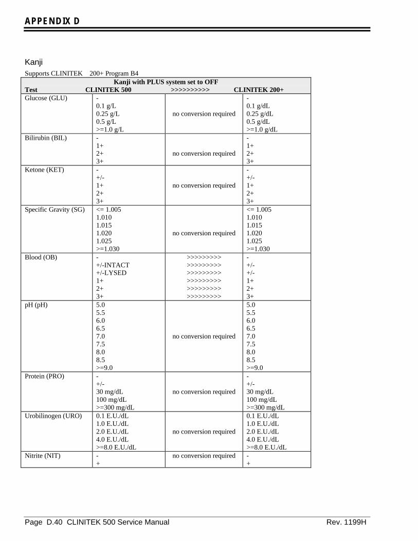
APPENDIX D
Page D.40 CLINITEK 500 Service Manual Rev. 1199H
KanjiSupports CLINITEK 200+ Program B4
Kanji with PLUS system set to OFFTest CLINITEK 500 >>>>>>>>>> CLINITEK 200+Glucose (GLU) -
0.1 g/L0.25 g/L0.5 g/L>=1.0 g/L
no conversion required
-0.1 g/dL0.25 g/dL0.5 g/dL>=1.0 g/dL
Bilirubin (BIL) -1+2+3+
no conversion required
-1+2+3+
Ketone (KET) -+/-1+2+3+
no conversion required
-+/-1+2+3+
Specific Gravity (SG) <= 1.0051.0101.0151.0201.025>=1.030
no conversion required
<= 1.0051.0101.0151.0201.025>=1.030
Blood (OB) -+/-INTACT+/-LYSED1+2+3+
>>>>>>>>>>>>>>>>>>>>>>>>>>>>>>>>>>>>>>>>>>>>>>>>>>>>>>
-+/-+/-1+2+3+
pH (pH) 5.05.56.06.57.07.58.08.5>=9.0
no conversion required
5.05.56.06.57.07.58.08.5>=9.0
Protein (PRO) -+/-30 mg/dL100 mg/dL>=300 mg/dL
no conversion required
-+/-30 mg/dL100 mg/dL>=300 mg/dL
Urobilinogen (URO) 0.1 E.U./dL1.0 E.U./dL2.0 E.U./dL4.0 E.U./dL>=8.0 E.U./dL
no conversion required
0.1 E.U./dL1.0 E.U./dL2.0 E.U./dL4.0 E.U./dL>=8.0 E.U./dL
Nitrite (NIT) -+
no conversion required -+

APPENDIX D
Rev.1199H CLINITEK 500 Service Manual Page D.41
Kanji with PLUS system set to OFFTest CLINITEK 500 >>>>>>>>>> CLINITEK 200+Leukocytes (WBC) -
+/-1+2+3+
no conversion required
-+/-1+2+3+
Color (COL)LT. YELLOWYELLOWDK. YELLOWLT. ORANGEORANGEDK. ORANGELT. REDREDDK. REDLT. GREENGREENDK. GREENLT. BLUEBLUEDK. BLUELT. BROWNBROWNDK. BROWN
COL >>>>>> Colore>>>>>>>>>>>>>>>>>>>>>>>>>>>>>>>>>>>>>>>>>>>>>>>>>>>>>>>>>>>>>>>>>>>>>>>>>>>>>>>>>>>>>>>>>>>>>>>>>>>>>>>>>>>>>>>>>>>>>>>>>>>>>>>>>>>>>>>>>>>>>>>>>>>>>>>>>>>>>>>>>>
STRAWYELLOWDK. YELLOWAMBERORANGEORANGEREDREDREDGREENGREENGREENOTHEROTHEROTHEROTHEROTHEROTHER
Clarity (CLA)-+/-1+2+3+
CLA >>>>>> Aspetto
no conversion required-+/-1+2+3+
Invalid Result Value ERROR no conversion required ERROR

APPENDIX D
Page D.42 CLINITEK 500 Service Manual Rev. 1199H
Supports CLINITEK 200+ Program B40101Kanji with PLUS system set to ON
Test CLINITEK 500 >>>>>>>>>> CLINITEK 200+Glucose (GLU) -
+/-1+2+3+
no conversion required
-+/-1+2+3+
Bilirubin (BIL) -1+2+3+
no conversion required
-1+2+3+
Ketone (KET) -+/-1+2+3+
no conversion required
-+/-1+2+3+
Specific Gravity (SG) <= 1.0051.0101.0151.0201.025>=1.030
no conversion required
<= 1.0051.0101.0151.0201.025>=1.030
Blood (OB) -+/-INTACT+/-LYSED1+2+3+
>>>>>>>>>>>>>>>>>>>>>>>>>>>>>>>>>>>>>>>>>>>>>>>>>>>>>>
-+/-+/-1+2+3+
pH (pH) 5.05.56.06.57.07.58.08.5>=9.0
no conversion required
5.05.56.06.57.07.58.08.5>=9.0
Protein (PRO) -+/-1+2+3+
no conversion required
-+/-1+2+3+
Urobilinogen (URO) 0.1 E.U./dL1.0 E.U./dL2.0 E.U./dL4.0 E.U./dL>=8.0 E.U./dL
no conversion required
0.1 E.U./dL1.0 E.U./dL2.0 E.U./dL4.0 E.U./dL>=8.0 E.U./dL
Nitrite (NIT) -+
no conversion required -+
Leukocytes (WBC) -+/-1+2+3+
no conversion required
-+/-1+2+3+

APPENDIX D
Rev.1199H CLINITEK 500 Service Manual Page D.43
Kanji with PLUS system set to ONTest CLINITEK 500 >>>>>>>>>> CLINITEK 200+Color (COL)
LT. YELLOWYELLOWDK. YELLOWLT. ORANGEORANGEDK. ORANGELT. REDREDDK. REDLT. GREENGREENDK. GREENLT. BLUEBLUEDK. BLUELT. BROWNBROWNDK. BROWN
COL >>>>>> Colore>>>>>>>>>>>>>>>>>>>>>>>>>>>>>>>>>>>>>>>>>>>>>>>>>>>>>>>>>>>>>>>>>>>>>>>>>>>>>>>>>>>>>>>>>>>>>>>>>>>>>>>>>>>>>>>>>>>>>>>>>>>>>>>>>>>>>>>>>>>>>>>>>>>>>>>>>>>>>>>>>>
STRAWYELLOWDK. YELLOWAMBERORANGEORANGEREDREDREDGREENGREENGREENOTHEROTHEROTHEROTHEROTHEROTHER
Clarity (CLA)-+/-1+2+OTHER
CLA >>>>>> Aspetto
no conversion required-+/-1+2+OTHER
Invalid Result Value ERROR no conversion required ERROR

APPENDIX D
Page D.44 CLINITEK 500 Service Manual Rev. 1199H
SpanishSupports CLINITEK 200+ Program D4
Spanish with PLUS system set to OFFTest CLINITEK 500 >>>>>>>>>> CLINITEK 200+Glucose (GLU) NEGATIVO
100 mg/dL250 mg/dL500 mg/dL>=1000 mg/dL
no conversion required
NEGATIVO100 mg/dL250 mg/dL500 mg/dL>=1000 mg/dL
Bilirubin (BIL) NEGATIVOBAJOMODERADOALTO
no conversion required
NEGATIVOBAJOMODERADOALTO
Ketone (CET) NEGATIVOINDICIOS15 mg/dL40 mg/dL>=80 mg/dL
>>>>>>>>>>>>>>>>>>>>>>>>>>>>>>>>>>>>>>>>>>>>>
NEGATIVOINDICIO15 mg/dL40 mg/dL>=80 mg/dL
Specific Gravity(DEN)
<= 1.0051.0101.0151.0201.025>=1.030
no conversion required
<= 1.0051.0101.0151.0201.025>=1.030
Blood (SAN) NEGATIVOIND.INTACTOSIND.HEMOLIZ.Apr 25 Hem/uLApr 80 Hem/uLApr 200 Hem/uL
>>>>>>>>>>>>>>>>>>>>>>>>>>>>>>>>>>>>>>>>>>>>>>>>>>>>>>
NEGATIVOApr 10 eri/uLApr 10 eri/uLApr 25 eri/uLApr 80 eri/uLApr 200 eri/uL
pH (pH) 5.05.56.06.57.07.58.08.5>=9.0
no conversion required
5.05.56.06.57.07.58.08.5>=9.0
Protein (PRO) NEGATIVOINDICIOS30 mg/dL100 mg/dL>=300 mg/dL
no conversion required
NEGATIVOINDICIO30 mg/dL100 mg/dL>=300 mg/dL
Urobilinogen (URO) 0.2 U.E./dL1.0 U.E./dL2.0 U.E./dL4.0 U.E./dL>=8.0 U.E./dL
>>>>>>>>>>>>>>>>>>>>>>>>>>>>>>>>>>>>>>>>>>>>>
0.2 E.U./dL1.0 E.U./dL2.0 E.U./dL4.0 E.U./dL>=8.0 E.U./dL
Nitrite (NIT) NEGATIVOPOSITIVO
no conversion required NEGATIVOPOSITIVO

APPENDIX D
Rev.1199H CLINITEK 500 Service Manual Page D.45
Spanish with PLUS system set to OFFTest CLINITEK 500 >>>>>>>>>> CLINITEK 200+Leukocytes (LEU) NEGATIVO
Apr 15 Leu/uLApr 70 Leu/uLApr 125 Leu/uLApr 500 Leu/uL
>>>>>>>>>>>>>>>>>>>>>>>>>>>>>>>>>>>>>>>>>>>>>
NEGATIVOApr 15 cel/uLApr 70 cel/uLApr 125 cel/uLApr 500 cel/uL
Color (COL)CL. AMARILLOAMARILLOOSC. AMARILLOCL. NARANJANARANJAOSC. NARANJACL. ROJOROJOOSC. ROJOCL. VERDEVERDEOSC. VERDECL. AZULAZULOSC. AZULCL. MARRONMARRONOSC. MARRON
COL >>>>>> Color>>>>>>>>>>>>>>>>>>>>>>>>>>>>>>>>>>>>>>>>>>>>>>>>>>>>>>>>>>>>>>>>>>>>>>>>>>>>>>>>>>>>>>>>>>>>>>>>>>>>>>>>>>>>>>>>>>>>>>>>>>>>>>>>>>>>>>>>>>>>>>>>>>>>>>>>>>>>>>>>>>
COLURICAAMARILLOAM. OSCUROAMBARANARANJANARANJROJIZOROJIZOROJIZOVERDOSOVERDOSOVERDOSOOTROSOTROSOTROSOTROSOTROSOTROS
Clarity (ASP)CLAROLIG. TURBTURBIAMUY TURBOTROS
ASP >>>>>> Aspecto
no conversion requiredCLAROLIG. TURBTURBIAMUY TURBOTROS
Invalid Result Value ERROR no conversion required ERROR

APPENDIX D
Page D.46 CLINITEK 500 Service Manual Rev. 1199H
Support for CLINITEK 200+ Program D40100Spanish with PLUS system set to ON
Test CLINITEK 500 >>>>>>>>>> CLINITEK 200+Glucose (GLU) NEGATIVO
INDICIOS1+2+3+
>>>>>>>>>>>>>>>>>>>>>>>>>>>>>>>>>>>>>>>>>>>>>
NEGATIVOINDICIO1+2+3+
Bilirubin (BIL) NEGATIVO1+2+3+
no conversion required
NEGATIVO1+2+3+
Ketone (CET) NEGATIVOINDICIOS1+2+3+
>>>>>>>>>>>>>>>>>>>>>>>>>>>>>>>>>>>>>>>>>>>>>
NEGATIVOINDICIO1+2+3+
Specific Gravity(DEN)
<= 1.0051.0101.0151.0201.025>=1.030
no conversion required
<= 1.0051.0101.0151.0201.025>=1.030
Blood (SAN) NEGATIVOIND. INTACTOSIND.HEMOLIZ.1+2+3+
>>>>>>>>>>>>>>>>>>>>>>>>>>>>>>>>>>>>>>>>>>>>>>>>>>>>>>
NEGATIVOINDICIOINDICIO1+2+3+
pH (pH) 5.05.56.06.57.07.58.08.5>=9.0
no conversion required
5.05.56.06.57.07.58.08.5>=9.0
Protein (PRO) NEGATIVOINDICIOS1+2+3+
>>>>>>>>>>>>>>>>>>>>>>>>>>>>>>>>>>>>>>>>>>>>>
NEGATIVOINDICIO1+2+3+
Urobilinogen (URO) 0.2 U.E./dL1.0 U.E./dL2.0 U.E./dL4.0 U.E./dL>=8.0 U.E./dL
>>>>>>>>>>>>>>>>>>>>>>>>>>>>>>>>>>>>>>>>>>>>>
0.2 E.U./dL1.0 E.U./dL2.0 E.U./dL4.0 E.U./dL>=8.0 E.U./dL
Nitrite (NIT) NEGATIVOPOSITIVO
no conversion required NEGATIVOPOSITIVO
Leukocytes (LEU) NEGATIVOINDICIOS1+2+3+
>>>>>>>>>>>>>>>>>>>>>>>>>>>>>>>>>>>>>>>>>>>>>
NEGATIVOINDICIO1+2+3+
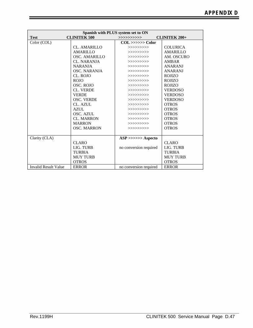
APPENDIX D
Rev.1199H CLINITEK 500 Service Manual Page D.47
Spanish with PLUS system set to ONTest CLINITEK 500 >>>>>>>>>> CLINITEK 200+Color (COL)
CL. AMARILLOAMARILLOOSC. AMARILLOCL. NARANJANARANJAOSC. NARANJACL. ROJOROJOOSC. ROJOCL. VERDEVERDEOSC. VERDECL. AZULAZULOSC. AZULCL. MARRONMARRONOSC. MARRON
COL >>>>>> Color>>>>>>>>>>>>>>>>>>>>>>>>>>>>>>>>>>>>>>>>>>>>>>>>>>>>>>>>>>>>>>>>>>>>>>>>>>>>>>>>>>>>>>>>>>>>>>>>>>>>>>>>>>>>>>>>>>>>>>>>>>>>>>>>>>>>>>>>>>>>>>>>>>>>>>>>>>>>>>>>>>
COLURICAAMARILLOAM. OSCUROAMBARANARANJANARANJROJIZOROJIZOROJIZOVERDOSOVERDOSOVERDOSOOTROSOTROSOTROSOTROSOTROSOTROS
Clarity (CLA)CLAROLIG. TURBTURBIAMUY TURBOTROS
ASP >>>>>> Aspecto
no conversion requiredCLAROLIG. TURBTURBIAMUY TURBOTROS
Invalid Result Value ERROR no conversion required ERROR
APPENDIX D
Page D.48 CLINITEK 500 Service Manual Rev. 1199H

APPENDIX E
Rev. 1199H CLINITEK 500 Service Manual Page E.1
APPENDIX E – Printer Report Formats Return
Printer Report FormatsThis section defines the report formats used for al printed reports. Three different printers are supported: the CLINITEK 500 internal printer, an 80 column printer and a Form printer. Not all report formats are available for allprinters. Printer selections are made on the “Printer Options” screen
Calibration ConfirmationThis report is available from Screen: Report Options.
Printer Priorities:If both the internal printer and an 80-column printer are set to ON, results are printed on the internal printer.
This report is not available for the Form printer.
Printer Format:
line 1 CLINITEK 500line 2 Calibration Successfulline 3 AAAAAAAA BBBBBBBB
Variable Field Descriptions:A: Represents the date of the test. The date is displayed in the date format set onScreen: Protected Setup (2/8).B: Represents the time of the test. The time is displayed in the time format set on Protected Setup (2/8)..
Load List ReportThis report is available by pressing the Print button from Scree: Sample ID Entry or Screen: Report Options.
Printer Priorities:If both the internal printer and an 80 column printer are set to ON, results are printed on the internal printer.
This report is not available for the Form printer.
Printer Format: There will be a maximum of three lines printed for each entry in the load list and a minimum of one line.
line 1 CLINITEK 500line 2 Load Listline 1 AAA. BBBBBBBBBBBBB CCCCline 2 DDD EEEEEEEEEEEEEEEline 3 FFF GGGGGGGGGGGGGGGline 4 AAA. BBBBBBBBBBBBB CCCCline 5 DDD EEEEEEEEEEEEEEEline 6 FFF GGGGGGGGGGGGGGG
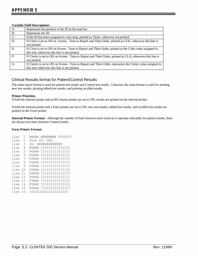
APPENDIX E
Page E.2 CLINITEK 500 Service Manual Rev. 1199H
Variable Field Descriptions:A: Represents the position of the ID in the load list.B: Represents the ID.C: If the ID has been assigned to a test strip, printed as 'Done'; otherwise not printed.D: If Color is set to ON on Screen: Tests to Report and Their Order, printed as COL; otherwise this line is
not printed.E: If Color is set to ON on Screen: Tests to Report and Their Order, printed as the Color value assigned to
this test; otherwise this line is not printed.F: If Clarity is set to ON on Screen: Tests to Report and Their Order, printed as CLA; otherwise this line is
not printed.G: If Clarity is set to ON on Screen: Tests to Report and Their Order, represents the Clarity value assigned to
this test; otherwise this line is not printed.
Clinical Results format for Patient/Control ResultsThe same report format is used for patient test results and Control test results. Likewise, the same format is used for printingnew test results, printing edited test results, and printing recalled results.
Printer Priorities:If both the internal printer and an 80 column printer are set to ON, results are printed on the internal printer.
If both the internal printer and a Form printer are set to ON, new test results, edited test results, and recalled test results areprinted on the Form printer.
Internal Printer Format: Although the number of lines between each result set is operator selectable for patient results, thereare always two lines between Control results.
Form Printer Format:
line 1 AAAAA BBBBBBBB CCCCCCCline 2 Tech ID: DDDline 3 ID: EEEEEEEEEEEEEline 4 FGHHH IIIIIIIIIIIIIIIline 5 FGHHH IIIIIIIIIIIIIIIline 6 FGHHH IIIIIIIIIIIIIIIline 7 FGHHH IIIIIIIIIIIIIIIline 8 FGHHH IIIIIIIIIIIIIIIline 9 FGHHH IIIIIIIIIIIIIIIline 10 FGHHH IIIIIIIIIIIIIIIline 11 FGHHH IIIIIIIIIIIIIIIline 12 FGHHH IIIIIIIIIIIIIIIline 13 FGHHH IIIIIIIIIIIIIIIline 14 FGHHH IIIIIIIIIIIIIIIline 15 FGHHH IIIIIIIIIIIIIIIline 16 JJJJJJJJJJJJJJJJJJJJ
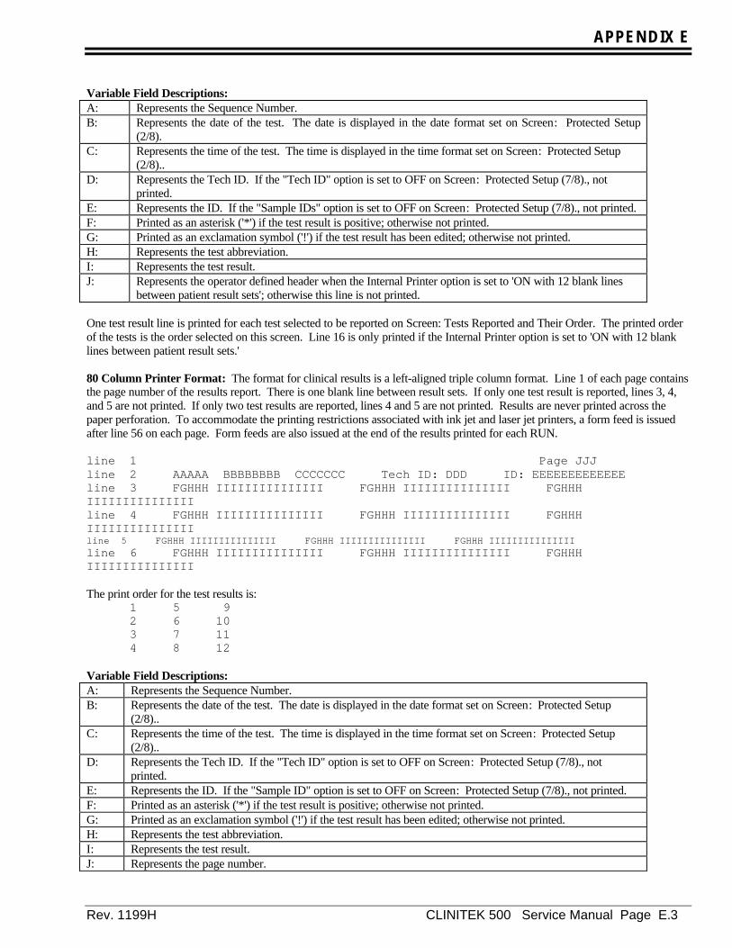
APPENDIX E
Rev. 1199H CLINITEK 500 Service Manual Page E.3
Variable Field Descriptions:A: Represents the Sequence Number.B: Represents the date of the test. The date is displayed in the date format set on Screen: Protected Setup
(2/8).C: Represents the time of the test. The time is displayed in the time format set on Screen: Protected Setup
(2/8)..D: Represents the Tech ID. If the "Tech ID" option is set to OFF on Screen: Protected Setup (7/8)., not
printed.E: Represents the ID. If the "Sample IDs" option is set to OFF on Screen: Protected Setup (7/8)., not printed.F: Printed as an asterisk ('*') if the test result is positive; otherwise not printed.G: Printed as an exclamation symbol ('!') if the test result has been edited; otherwise not printed.H: Represents the test abbreviation.I: Represents the test result.J: Represents the operator defined header when the Internal Printer option is set to 'ON with 12 blank lines
between patient result sets'; otherwise this line is not printed.
One test result line is printed for each test selected to be reported on Screen: Tests Reported and Their Order. The printed orderof the tests is the order selected on this screen. Line 16 is only printed if the Internal Printer option is set to 'ON with 12 blanklines between patient result sets.'
80 Column Printer Format: The format for clinical results is a left-aligned triple column format. Line 1 of each page containsthe page number of the results report. There is one blank line between result sets. If only one test result is reported, lines 3, 4,and 5 are not printed. If only two test results are reported, lines 4 and 5 are not printed. Results are never printed across thepaper perforation. To accommodate the printing restrictions associated with ink jet and laser jet printers, a form feed is issuedafter line 56 on each page. Form feeds are also issued at the end of the results printed for each RUN.
line 1 Page JJJline 2 AAAAA BBBBBBBB CCCCCCC Tech ID: DDD ID: EEEEEEEEEEEEEline 3 FGHHH IIIIIIIIIIIIIII FGHHH IIIIIIIIIIIIIII FGHHHIIIIIIIIIIIIIIIline 4 FGHHH IIIIIIIIIIIIIII FGHHH IIIIIIIIIIIIIII FGHHHIIIIIIIIIIIIIIIline 5 FGHHH IIIIIIIIIIIIIII FGHHH IIIIIIIIIIIIIII FGHHH IIIIIIIIIIIIIIIline 6 FGHHH IIIIIIIIIIIIIII FGHHH IIIIIIIIIIIIIII FGHHHIIIIIIIIIIIIIII
The print order for the test results is:1 5 92 6 103 7 114 8 12
Variable Field Descriptions:A: Represents the Sequence Number.B: Represents the date of the test. The date is displayed in the date format set on Screen: Protected Setup
(2/8)..C: Represents the time of the test. The time is displayed in the time format set on Screen: Protected Setup
(2/8)..D: Represents the Tech ID. If the "Tech ID" option is set to OFF on Screen: Protected Setup (7/8)., not
printed.E: Represents the ID. If the "Sample ID" option is set to OFF on Screen: Protected Setup (7/8)., not printed.F: Printed as an asterisk ('*') if the test result is positive; otherwise not printed.G: Printed as an exclamation symbol ('!') if the test result has been edited; otherwise not printed.H: Represents the test abbreviation.I: Represents the test result.J: Represents the page number.
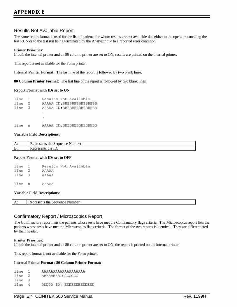
APPENDIX E
Page E.4 CLINITEK 500 Service Manual Rev. 1199H
Results Not Available ReportThe same report format is used for the list of patients for whom results are not available due either to the operator canceling thetest RUN or to the test run being terminated by the Analyzer due to a reported error condition.
Printer Priorities:If both the internal printer and an 80 column printer are set to ON, results are printed on the internal printer.
This report is not available for the Form printer.
Internal Printer Format: The last line of the report is followed by two blank lines.
80 Column Printer Format: The last line of the report is followed by two blank lines.
Report Format with IDs set to ON
line 1 Results Not Availableline 2 AAAAA ID:BBBBBBBBBBBBBBBline 3 AAAAA ID:BBBBBBBBBBBBBBB
.
.
.line n AAAAA ID:BBBBBBBBBBBBBBB
Variable Field Descriptions:
A: Represents the Sequence Number.B: Represents the ID.
Report Format with IDs set to OFF
line 1 Results Not Availableline 2 AAAAAline 3 AAAAA
line n AAAAA
Variable Field Descriptions:
A: Represents the Sequence Number.
Confirmatory Report / Microscopics ReportThe Confirmatory report lists the patients whose tests have met the Confirmatory flags criteria. The Microscopics report lists thepatients whose tests have met the Microscopics flags criteria. The format of the two reports is identical. They are differentiatedby their header.
Printer Priorities:If both the internal printer and an 80 column printer are set to ON, the report is printed on the internal printer.
This report format is not available for the Form printer.
Internal Printer Format / 80 Column Printer Format:
line 1 AAAAAAAAAAAAAAAAAAA line 2 BBBBBBBB CCCCCCCline 3line 4 DDDDD ID: EEEEEEEEEEEEE

APPENDIX E
Rev. 1199H CLINITEK 500 Service Manual Page E.5
line 5 FFF FFF FFF FFF FFFline 6line 7 DDDDD ID: EEEEEEEEEEEEEline 8 FFF FFF FFF FFF FFF
Variable Field Descriptions:A: Printed as Confirmatory Report or Microscopics Report.B: Represents the date of the RUN. The date is displayed in the date format set on Screen: Protected Setup
(2/8)..C: Represents the time of the RUN. The time is displayed in the time format set on Screen: Protected Setup
(2/8)..D: Represents the Sequence Number.E: Represents the ID. If the "Sample IDs" option is set to OFF on Screen: Protected Setup (7/8)., not printed.F: Represents the test which met the report criteria.
Two lines are printed for each patient. One blank line separates patient data.
Results Error ReportThe Results Error report lists the samples for which clinical results are not available because an error was reported during thecalculation of at least one of the results. This type of an error is not an instrument or system error, it affects only the results ofthe sample for which the error is reported and does not stop the RUN. This report is displayed after the Confirmatory andMicroscopic reports.
Printer Priorities:If both the internal printer and an 80 column printer are set to ON, the report is printed on the internal printer.
This report format is not available for the Form printer.

APPENDIX E
Page E.6 CLINITEK 500 Service Manual Rev. 1199H
Internal Printer Format / 80 Column Printer Format:
line 1 Results Error Reportline 2 AAAAAAAA BBBBBBBline 3line 4 CCCCC ID: DDDDDDDDDDDDDline 5 CCCCC ID: DDDDDDDDDDDDD
line n CCCCC ID: DDDDDDDDDDDDD
Variable Field Descriptions:A: Represents the date of the RUN. The date is displayed in the date format set on Screen: Protected Setup
(2/8)..B: Represents the time of the RUN. The time is displayed in the time format set on Screen: Protected Setup
(2/8)..C: Represents the Sequence Number.D: Represents the ID. If the "Sample IDs" option is set to OFF on Screen: Protected Setup (7/8)., not printed.
One line is printed for each sample.
System Configuration ReportThis report lists the operator selectable options and their current setting.
Printer Priorities:If both the internal printer and an 80 column printer are set to ON, this report is printed on the 80 column printer.
This report is not available for the Form printer.
Internal Printer Format: The printer advances two lines after the report has been printed.
line 1 CLINITEK 500line 2 System Configurationline 3 AAAAAAAA BBBBBBBline 4 Software Version:line 5 CC.CC/CC.CCline 6line 7 User Interface Settingsline 8 Language:line 9 DDDDDDDline 10 Result units:line 11 DDDDDDDDDDDDline 12 PLUS system:line 13 DDDline 14 Date format:line 15 DDDDDDDDline 16 Test:line 17 DDDDDDDDDDDDDDDDDDDDDDline 18 Date separator:line 19 DDDline 20 Time format:line 21 DDDDDDD
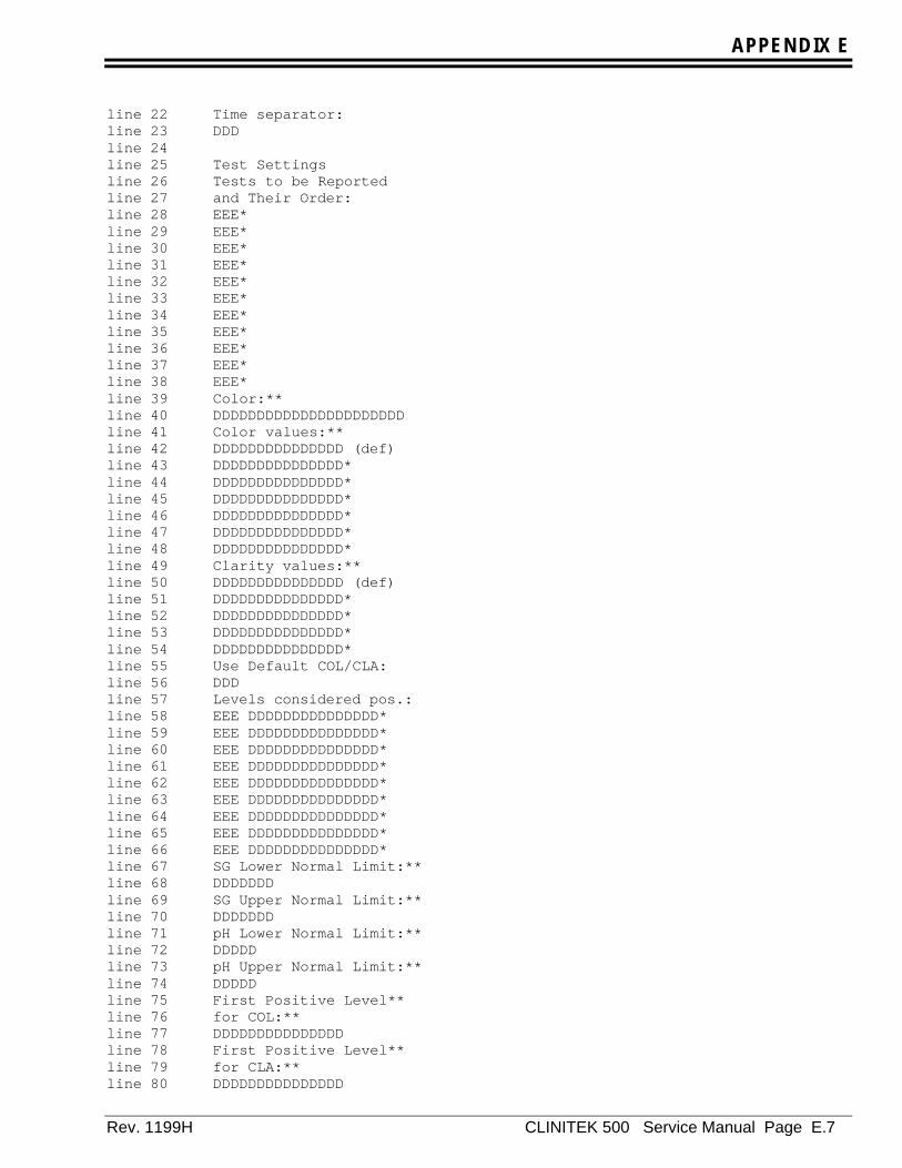
APPENDIX E
Rev. 1199H CLINITEK 500 Service Manual Page E.7
line 22 Time separator:line 23 DDDline 24line 25 Test Settingsline 26 Tests to be Reportedline 27 and Their Order:line 28 EEE*line 29 EEE*line 30 EEE*line 31 EEE*line 32 EEE*line 33 EEE*line 34 EEE*line 35 EEE*line 36 EEE*line 37 EEE*line 38 EEE*line 39 Color:**line 40 DDDDDDDDDDDDDDDDDDDDDDline 41 Color values:**line 42 DDDDDDDDDDDDDDD (def)line 43 DDDDDDDDDDDDDDD*line 44 DDDDDDDDDDDDDDD*line 45 DDDDDDDDDDDDDDD*line 46 DDDDDDDDDDDDDDD*line 47 DDDDDDDDDDDDDDD*line 48 DDDDDDDDDDDDDDD*line 49 Clarity values:**line 50 DDDDDDDDDDDDDDD (def)line 51 DDDDDDDDDDDDDDD*line 52 DDDDDDDDDDDDDDD*line 53 DDDDDDDDDDDDDDD*line 54 DDDDDDDDDDDDDDD*line 55 Use Default COL/CLA:line 56 DDDline 57 Levels considered pos.:line 58 EEE DDDDDDDDDDDDDDD*line 59 EEE DDDDDDDDDDDDDDD*line 60 EEE DDDDDDDDDDDDDDD*line 61 EEE DDDDDDDDDDDDDDD*line 62 EEE DDDDDDDDDDDDDDD*line 63 EEE DDDDDDDDDDDDDDD*line 64 EEE DDDDDDDDDDDDDDD*line 65 EEE DDDDDDDDDDDDDDD*line 66 EEE DDDDDDDDDDDDDDD*line 67 SG Lower Normal Limit:**line 68 DDDDDDDline 69 SG Upper Normal Limit:**line 70 DDDDDDDline 71 pH Lower Normal Limit:**line 72 DDDDDline 73 pH Upper Normal Limit:**line 74 DDDDDline 75 First Positive Level**line 76 for COL:**line 77 DDDDDDDDDDDDDDDline 78 First Positive Level**line 79 for CLA:**line 80 DDDDDDDDDDDDDDD

APPENDIX E
Page E.8 CLINITEK 500 Service Manual Rev. 1199H
line 81 Confirmatory Flags:***line 82 EEE EEE EEE EEE EEEline 83 Microscopics Flags:***line 84 EEE EEE EEE EEE EEEline 85 Edit flagged results:line 86 DDDline 87 Tests Using Alteredline 88 Ranges****line 89 EEE EEE EEE EEEline 90 EEE EEE EEE EEEline 91line 92 System Settingsline 93 Tech ID:line 94 DDDline 95 Sample IDs:line 96 DDDline 97 Password for Setup:line 98 DDDline 99 Internal printer:line 100 DDDDDDDDDDDDDDDDline 101 External printer:line 102 DDDDDDDDDline 103 Custom Header:*****line 104 DDDDDDDDDDDDDDDDDDDDline 105 Computer linkline 106 Port:line 107 OFFline 108 Baud Rate:line 109 DDDDDDline 110 Data Bits/Par.:line 111 DDDDDDline 112 Output Format:line 113 DDDDDDline 114 Checksum:line 115 DDDDDD******line 116 Handshake:line 117 DDDDDD******line 118 Label:line 119 DDDline 120 Ignore Lead BC Char.:line 121 0line 122 Ignore Trail BC Char.:line 123 0
Variable Field Descriptions:A: Represents the date of the test. The date is displayed in the date format set on Screen: Protected Setup
(2/8)..B: Represents the time of the test. The time is displayed in the time format set on Screen: Protected Setup
(2/8)..C: Represents the Software Versions of the processors.D: Represents the current option for a system setting.E: Represents a test abbreviation.
* This line is not printed if the corresponding test is not selected on Screen: Tests to Report and Their Order.** The option for this line is printed as 'N/A' if the corresponding test is not selected onScreen: Tests to Report
and Their Order.*** The option for this line is printed as 'None' if no tests are selected for the flag criteria.**** This option is not printed if Altered Ranges are not in use.

APPENDIX E
Rev. 1199H CLINITEK 500 Service Manual Page E.9
***** The option for this line is printed as 'N/A' if the Internal Printer option on Screen: Printer Options is NOTset to 'ON with 12 blank lines between patient result sets.
******
The option for this line is printed as 'N/A' if the Output Format is set to ‘CT500’.
80 Column Printer Format: The printer issues a form feed after the report has been printed.
line 1 System Configuration Page FFFline 2 AAAAAAAA BBBBBBBline 3 Software Version: CC.CC/CC.CCline 4line 5 User Interface Settingsline 6 Language: DDDDDDDline 7 Result units: DDDDDDDDDDDDDDDDDDDDline 8 PLUS system: DDDline 9 Test: DDDDDDDDDDDDDDDDDDDDDDDline 10 Date format: DDDDDDDDline 11 Date separator: DDDline 12 Time format: DDDDDDDline 13 Time separator: DDDline 14line 15 Test Settingsline 16 Tests to be Reported and Their Order:line 17 EEE EEE EEE EEE EEE EEE EEE EEE EEE EEE EEE EEEline 18 Color: DDDDDDDDDDDDDDDDDDDDDD**line 19 Color values:**line 20 DDDDDDDDDDDDDDD (default)line 21 DDDDDDDDDDDDDDD*line 22 DDDDDDDDDDDDDDD*line 23 DDDDDDDDDDDDDDD*line 24 DDDDDDDDDDDDDDD*line 25 DDDDDDDDDDDDDDD*line 26 DDDDDDDDDDDDDDD*line 27 Clarity values:**line 28 DDDDDDDDDDDDDDD (default)line 29 DDDDDDDDDDDDDDD*line 30 DDDDDDDDDDDDDDD*line 31 DDDDDDDDDDDDDDD*line 32 DDDDDDDDDDDDDDD*line 33 Use Default COL/CLA: DDDline 34 First Positive Level:line 35 EEE DDDDDDDDDDDDDDD*line 36 EEE DDDDDDDDDDDDDDD*line 37 EEE DDDDDDDDDDDDDDD*line 38 EEE DDDDDDDDDDDDDDD*line 39 EEE DDDDDDDDDDDDDDD*line 40 EEE DDDDDDDDDDDDDDD*line 41 EEE DDDDDDDDDDDDDDD*line 42 EEE DDDDDDDDDDDDDDD*line 43 EEE DDDDDDDDDDDDDDD*line 44 SG Lower Normal Limit: DDDDDDD**line 45 SG Upper Normal Limit: DDDDDDD**line 46 pH Lower Normal Limit: DDDDD**line 47 pH Upper Normal Limit: DDDDD**line 48 First Positive Level for COL: DDDDDDDDDDDDDDD**line 49 First Positive Level for CLA: DDDDDDDDDDDDDDD**line 50 Flags for Confirmatory Report: EEE EEE EEE EEE EEE***line 51 Flags for Microscopics Report: EEE EEE EEE EEE EEE***
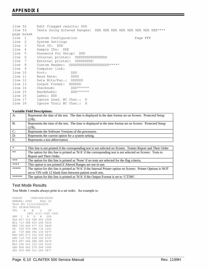
APPENDIX E
Page E.10 CLINITEK 500 Service Manual Rev. 1199H
line 52 Edit flagged results: DDDline 53 Tests Using Altered Ranges: EEE EEE EEE EEE EEE EEE EEE EEE****page breakline 1 System Configuration Page FFFline 2 System Settingsline 3 Tech ID: DDDline 4 Sample IDs: DDDline 5 Password for Setup: DDDline 6 Internal printer: DDDDDDDDDDDDDDDDline 7 External printer: DDDDDDDDDline 8 Custom Header: DDDDDDDDDDDDDDDDDDDD*****line 9 Computer link:line 10 Port: DDDline 11 Baud Rate: DDDDline 12 Data Bits/Par.: DDDDDDline 13 Output Format: DDDDDDline 14 Checksum: DDD******line 15 Handshake: DDD******line 16 Label: DDDline 17 Ignore Lead. BC Char.: Dline 18 Ignore Trail BC Char.: D
Variable Field Descriptions:A: Represents the date of the test. The date is displayed in the date format set on Screen: Protected Setup
(2/8)..B: Represents the time of the test. The time is displayed in the time format set on Screen: Protected Setup
(2/8)..C: Represents the Software Versions of the processors.D: Represents the current option for a system setting.E: Represents a test abbreviation.
* This line is not printed if the corresponding test is not selected on Screen: Teststo Report and Their Order** The option for this line is printed as 'N/A' if the corresponding test is not selected on Screen: Tests to
Report and Their Order.*** The option for this line is printed as 'None' if no tests are selected for the flag criteria.**** This option is not printed if Altered Ranges are not in use.***** The option for this line is printed as 'N/A' if the Internal Printer option on Screen: Printer Options is NOT
set to 'ON with 12 blank lines between patient result sets.****** The option for this line is printed as 'N/A' if the Output Format is set to ‘CT500’.
Test Mode ResultsTest Mode 1 results always print in a set order. An example is:
000006 19981006180200ERRORS: 0000 POS: 43Tech ID: 1111112222233ID: 3234567890123COL A B L CD +851 +113 +265 +000SRV I R G B DCDGLU 817 310 568 456 1558BIL 713 588 435 296 0610KET 734 604 477 331 0649SG 726 474 398 133 1201pH 719 486 392 130 0677PRO 695 273 332 235 0435URO 719 735 538 143 0747NIT 697 606 288 280 0476BLO 126 123 123 125 0124LEU 608 442 279 244 1000LE1 653 486 311 262 0477
APPENDIX E
Rev. 1199H CLINITEK 500 Service Manual Page E.11
Test Mode 2 results print Test Mode 1 results format, a blank line, and then the list of test labels and clinical result values.The clinical result portion of the printout is in the order as set by the Tests to Report and Their Order option.

APPENDIX E
Page E.12 CLINITEK 500 Service Manual Rev. 1199H
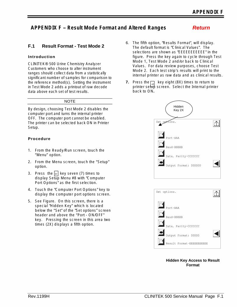
APPENDIX F
Rev.1199H CLINITEK 500 Service Manual Page F.1
>
F.1 Result Format - Test Mode 2
Introduction
CLINITEK® 500 Urine Chemistry AnalyzerCustomers who choose to alter instrumentranges should collect data from a statisticallysignificant number of samples for comparison tothe reference method(s). Setting the instrumentin Test Mode 2 adds a printout of raw decodedata above each set of test results.
NOTE
By design, choosing Test Mode 2 disables thecomputer port and turns the internal printerOFF. The computer port cannot be enabled.The printer can be selected back ON in PrinterSetup.
Procedure
1. From the Ready/Run screen, touch the“Menu” option.
2. From the Menu screen, touch the “Setup”option.
3. Press the key seven (7) times todisplay Setup Menu #8 with "ComputerPort Options" as the first selection.
4. Touch the "Computer Port Options" key todisplay the computer port options screen.
5. See Figure. On this screen, there is aspecial "Hidden Key” which is locatedbelow the “Set" of the "Set options" screenheader and above the “Port - ON/OFF"key. Pressing the screen in this area twotimes (2X) displays a fifth option.
6. The fifth option, "Results Format", will display.The default format is "Clinical Values". Theselections are shown as "EEEEEEEEEEE" in thefigure. Press the key again to cycle through TestMode 1, Test Mode 2 and/or back to ClinicalValues. For data review purposes, choose TestMode 2. Each test strip's results will print to theinternal printer as raw data and as clinical results.
7. Press the key eight (8X) times to return toprinter setup screen. Select the Internal printerback to ON.
<
Set options.
Baud-BBBBB
Data, Parity-CCCCCCC
Port-AAA
Output Format: DDDDD
Result Format-EEEEEEEEEEE
Set options.
Baud-BBBBB
Data, Parity-CCCCCCC
Port-AAA
Output Format: DDDDDD
HiddenKey 2X
Hidden Key Access to ResultFormat
APPENDIX F – Result Mode Format and Altered Ranges Return
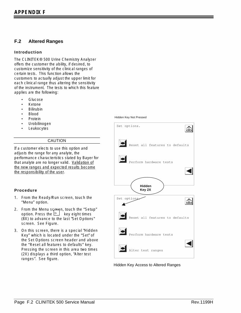
APPENDIX F
Page F.2 CLINITEK 500 Service Manual Rev.1199H
F.2 Altered Ranges
Introduction
The CLINITEK® 500 Urine Chemistry Analyzeroffers the customer the ability, if desired, tocustomize sensitivity of the clinical ranges ofcertain tests. This function allows thecustomers to actually adjust the upper limit foreach clinical range thus altering the sensitivityof the instrument. The tests to which this featureapplies are the following:
• Glucose• Ketone• Bilirubin• Blood• Protein• Urobilinogen• Leukocytes
CAUTION
If a customer elects to use this option andadjusts the range for any analyte, theperformance characteristics stated by Bayer forthat analyte are no longer valid. Validation ofthe new ranges and expected results becomethe responsibility of the user.
Procedure
1. From the Ready/Run screen, touch the“Menu” option.
2. From the Menu screen, touch the “Setup”option. Press the key eight times(8X) to advance to the last "Set Options"screen. See Figure.
3. On this screen, there is a special "HiddenKey” which is located under the “Set" ofthe Set Options screen header and abovethe “Reset all features to defaults“ key.Pressing the screen in this area two times(2X) displays a third option, "Alter testranges". See figure.
Hidden Key Not Pressed
Set options.
Reset all features to defaults
Perform hardware tests
Set options.
Reset all features to defaults
Perform hardware tests
Alter test ranges
HiddenKey 2X
Hidden Key Access to Altered Ranges
>
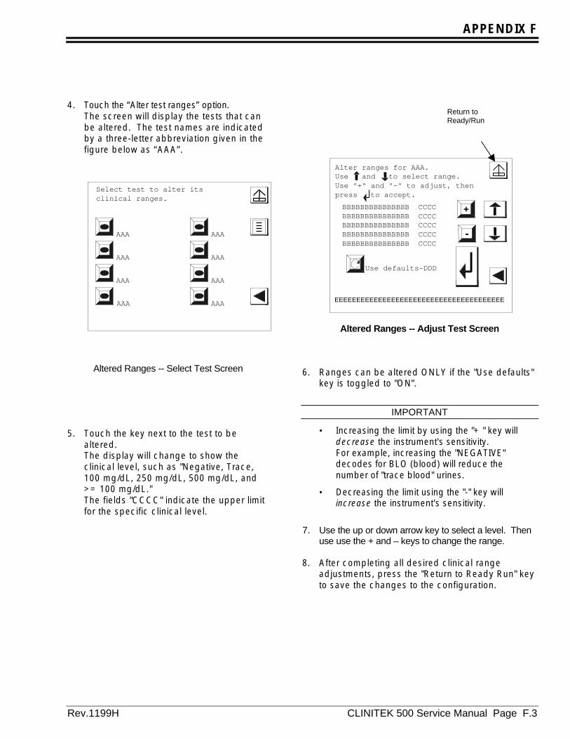
APPENDIX F
Rev.1199H CLINITEK 500 Service Manual Page F.3
4. Touch the “Alter test ranges” option.The screen will display the tests that canbe altered. The test names are indicatedby a three-letter abbreviation given in thefigure below as “AAA”.
Altered Ranges -- Select Test Screen
5. Touch the key next to the test to bealtered.The display will change to show theclinical level, such as "Negative, Trace,100 mg/dL, 250 mg/dL, 500 mg/dL, and>= 100 mg/dL."The fields "CCCC" indicate the upper limitfor the specific clinical level.
Altered Ranges -- Adjust Test Screen
6. Ranges can be altered ONLY if the "Use defaults"key is toggled to "ON".
IMPORTANT
• Increasing the limit by using the "+ " key willdecrease the instrument's sensitivity.For example, increasing the "NEGATIVE"decodes for BLO (blood) will reduce thenumber of "trace blood" urines.
• Decreasing the limit using the "-" key willincrease the instrument's sensitivity.
7. Use the up or down arrow key to select a level. Thenuse use the + and – keys to change the range.
8. After completing all desired clinical rangeadjustments, press the "Return to Ready Run" keyto save the changes to the configuration.
Select test to alter its clinical ranges.
AAA
AAA
AAA
AAA
AAA
AAA
AAA
AAA
Alter ranges for AAA.Use and to select range.Use "+" and "-" to adjust, thenpress to accept.
Use defaults-DDD
-
+BBBBBBBBBBBBBBB CCCCBBBBBBBBBBBBBBB CCCCBBBBBBBBBBBBBBB CCCCBBBBBBBBBBBBBBB CCCCBBBBBBBBBBBBBBB CCCC
EEEEEEEEEEEEEEEEEEEEEEEEEEEEEEEEEEEEEEEEE
Return toReady/Run

APPENDIX F
Page F.4 CLINITEK 500 Service Manual Rev.1199H
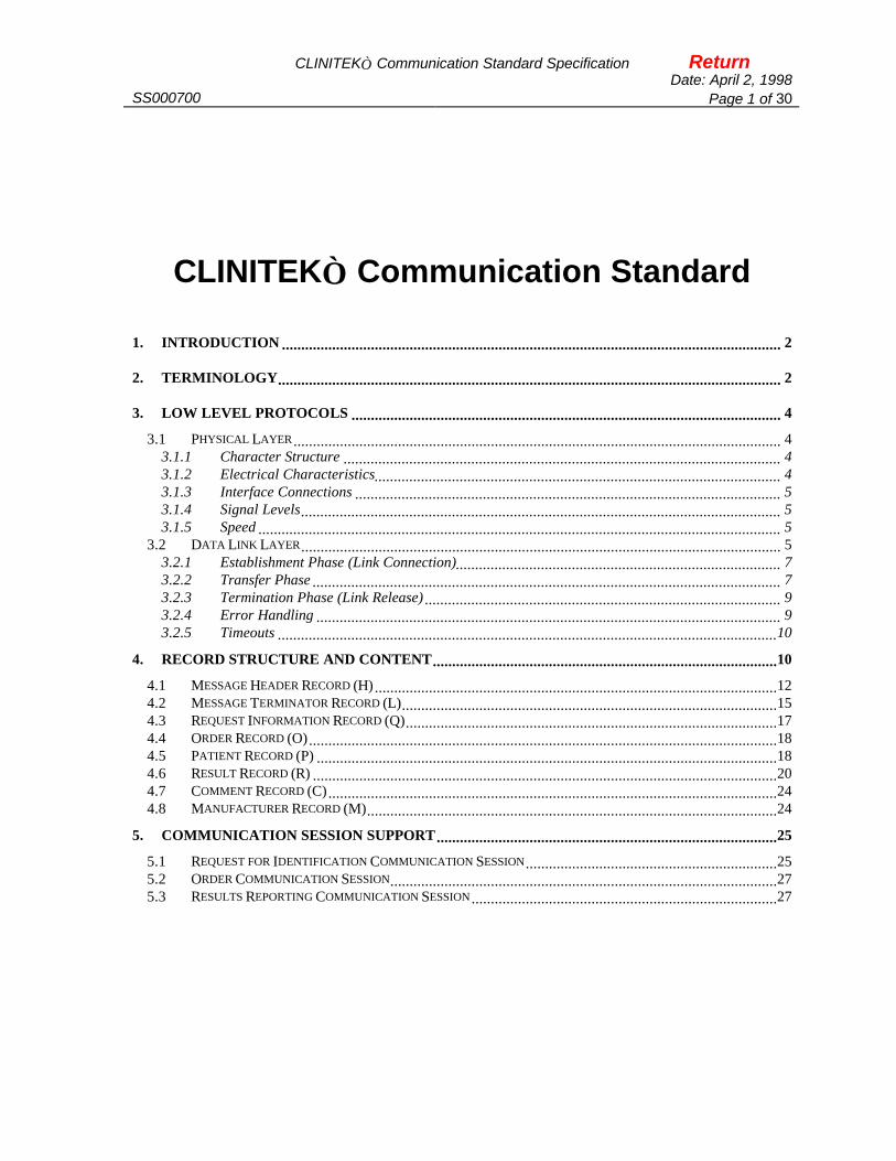
CLINITEK Communication Standard Specification ReturnDate: April 2, 1998
SS000700 Page 1 of 30
CLINITEK Communication Standard
1. INTRODUCTION ................................................................................................................................. 2
2. TERMINOLOGY.................................................................................................................................. 2
3. LOW LEVEL PROTOCOLS ............................................................................................................... 4
3.1 PHYSICAL LAYER.............................................................................................................................. 43.1.1 Character Structure ................................................................................................................. 43.1.2 Electrical Characteristics......................................................................................................... 43.1.3 Interface Connections .............................................................................................................. 53.1.4 Signal Levels............................................................................................................................ 53.1.5 Speed ....................................................................................................................................... 5
3.2 DATA LINK LAYER............................................................................................................................ 53.2.1 Establishment Phase (Link Connection).................................................................................... 73.2.2 Transfer Phase ......................................................................................................................... 73.2.3 Termination Phase (Link Release) ............................................................................................ 93.2.4 Error Handling ........................................................................................................................ 93.2.5 Timeouts .................................................................................................................................10
4. RECORD STRUCTURE AND CONTENT.........................................................................................10
4.1 MESSAGE HEADER RECORD (H)........................................................................................................124.2 MESSAGE TERMINATOR RECORD (L).................................................................................................154.3 REQUEST INFORMATION RECORD (Q)................................................................................................174.4 ORDER RECORD (O).........................................................................................................................184.5 PATIENT RECORD (P) .......................................................................................................................184.6 RESULT RECORD (R) ........................................................................................................................204.7 COMMENT RECORD (C)....................................................................................................................244.8 MANUFACTURER RECORD (M)..........................................................................................................24
5. COMMUNICATION SESSION SUPPORT........................................................................................25
5.1 REQUEST FOR IDENTIFICATION COMMUNICATION SESSION.................................................................255.2 ORDER COMMUNICATION SESSION....................................................................................................275.3 RESULTS REPORTING COMMUNICATION SESSION...............................................................................27
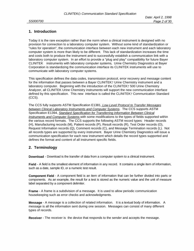
CLINITEK Communication Standard SpecificationDate: April 2, 1998
SS000700 Page 2 of 30
1. Introduction
Today it is the rare exception rather than the norm when a clinical instrument is designed with noprovision for connection to a laboratory computer system. Without some kind of standardization or"rules for operation", the communication interface between each new instrument and each laboratorycomputer system is more than likely to be different. This lack of standardization increases the timeand costs both to produce the instrument and to successfully establish a communication link with alaboratory computer system. In an effort to provide a "plug and play" compatibility for future BayerCLINITEK instruments with laboratory computer systems, Urine Chemistry Diagnostics at BayerCorporation is standardizing the communication interface its CLINITEK instruments will use tocommunicate with laboratory computer systems.
This specification defines the data codes, transmission protocol, error recovery and message contentfor the information that passes between a Bayer CLINITEK7 Urine Chemistry instrument and alaboratory computer. Beginning with the introduction of the CLINITEK7 500 Urine ChemistryAnalyzer, all CLINITEK Urine Chemistry instruments will support the new communication interfacedefined by this specification. This new interface is called the CLINITEK7 Communication Standard(CCS).
The CCS fully supports ASTM Specification E1381, Low-Level Protocol to Transfer Messagesbetween Clinical Laboratory Instruments and Computer Systems. The CCS supports ASTMSpecification E1394, Standard Specification for Transferring Information Between ClinicalInstruments and Computer Systems with some modifications to the types of fields supported withinthe various record formats. The CCS supports the following ASTM record types: Header records(H), Manufacturing records (M), Patient records (P), Result records (R), Test Order records (O),Request Information records (Q), Comment records (C), and Message Termination records (L). Notall records types are supported by every instrument. Bayer Urine Chemistry Diagnostics will issue acommunication specification for each new instrument which details the record types supported anddefines the format and content of all instrument specific fields.
2. Terminology
Download - Download is the transfer of data from a computer system to a clinical instrument.
Field - A field is the smallest element of information in any record. It contains a single item of information,such as a date, sample ID, or a numeric test result.
Component Field - A component field is an item of information that can be further divided into parts orcomponents. As an example, the result for a test is stored as the numeric value and the unit of measurelabel separated by a component delimiter.
Frame - A frame is a subdivision of a message. It is used to allow periodic communication housekeeping such as error checks and acknowledgments.
Message - A message is a collection of related information. It is a textual body of information. Amessage is all the information sent during one session. Messages can consist of many differenttypes of records.
Receiver - The receiver is the device that responds to the sender and accepts the message.

CLINITEK Communication Standard SpecificationDate: April 2, 1998
SS000700 Page 3 of 30
Record - A record is an aggregate of fields describing one aspect of the complete message.
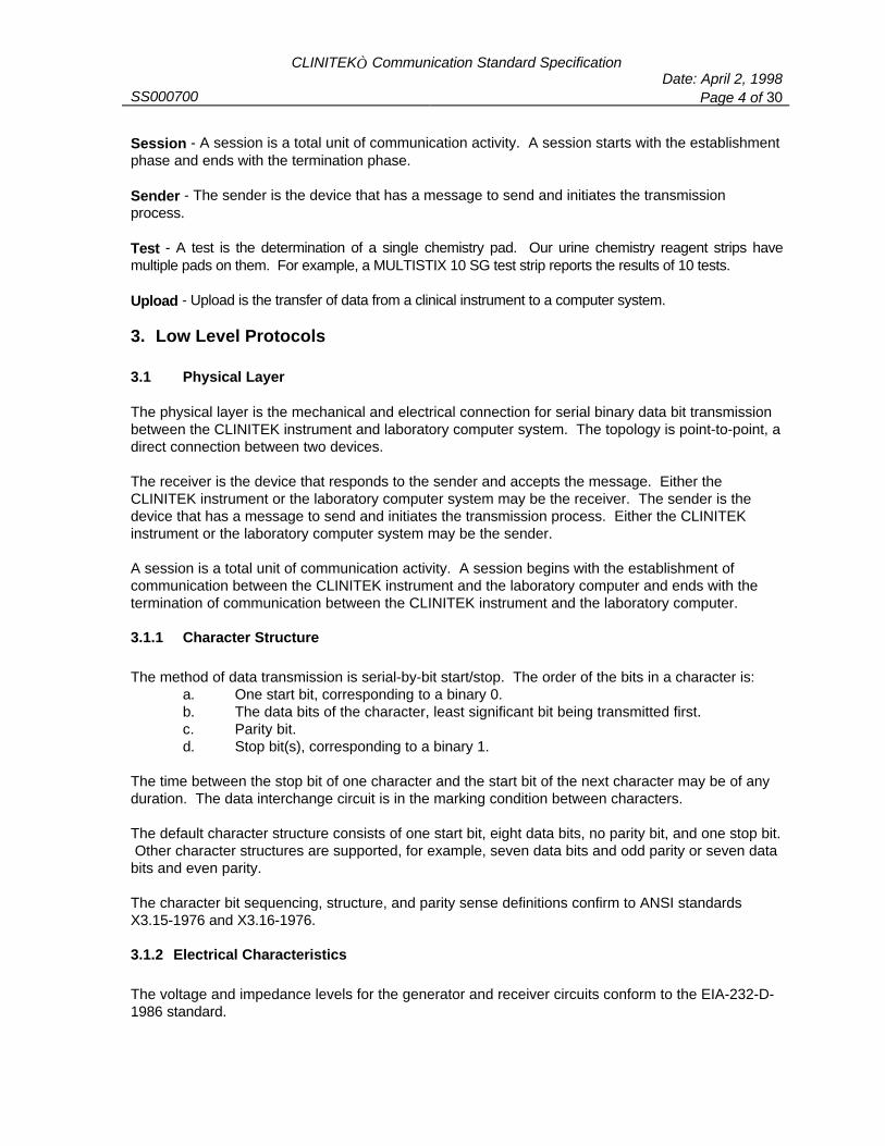
CLINITEK Communication Standard SpecificationDate: April 2, 1998
SS000700 Page 4 of 30
Session - A session is a total unit of communication activity. A session starts with the establishmentphase and ends with the termination phase.
Sender - The sender is the device that has a message to send and initiates the transmissionprocess.
Test - A test is the determination of a single chemistry pad. Our urine chemistry reagent strips havemultiple pads on them. For example, a MULTISTIX 10 SG test strip reports the results of 10 tests.
Upload - Upload is the transfer of data from a clinical instrument to a computer system.
3. Low Level Protocols
3.1 Physical Layer
The physical layer is the mechanical and electrical connection for serial binary data bit transmissionbetween the CLINITEK instrument and laboratory computer system. The topology is point-to-point, adirect connection between two devices.
The receiver is the device that responds to the sender and accepts the message. Either theCLINITEK instrument or the laboratory computer system may be the receiver. The sender is thedevice that has a message to send and initiates the transmission process. Either the CLINITEKinstrument or the laboratory computer system may be the sender.
A session is a total unit of communication activity. A session begins with the establishment ofcommunication between the CLINITEK instrument and the laboratory computer and ends with thetermination of communication between the CLINITEK instrument and the laboratory computer.
3.1.1 Character Structure
The method of data transmission is serial-by-bit start/stop. The order of the bits in a character is:a. One start bit, corresponding to a binary 0.b. The data bits of the character, least significant bit being transmitted first.c. Parity bit.d. Stop bit(s), corresponding to a binary 1.
The time between the stop bit of one character and the start bit of the next character may be of anyduration. The data interchange circuit is in the marking condition between characters.
The default character structure consists of one start bit, eight data bits, no parity bit, and one stop bit. Other character structures are supported, for example, seven data bits and odd parity or seven databits and even parity.
The character bit sequencing, structure, and parity sense definitions confirm to ANSI standardsX3.15-1976 and X3.16-1976.
3.1.2 Electrical Characteristics
The voltage and impedance levels for the generator and receiver circuits conform to the EIA-232-D-1986 standard.

CLINITEK Communication Standard SpecificationDate: April 2, 1998
SS000700 Page 5 of 30
3.1.3 Interface Connections
The CCS supports the connector requirements of ANSI standard E1381-91.
3.1.4 Signal Levels
For the data interchange circuits, a marking condition corresponds to a voltage more negative thanminus three volts with respect to signal ground at the interface point. A spacing conditioncorresponds to a voltage more positive than plus three volts with respect to signal ground at theinterface point.
Binary state ONE (1) corresponds to the marking condition; binary state ZERO (0) corresponds to thespacing condition.
The signal levels conform to the EIA-232-D-1986 standard.
3.1.5 Speed
The default data transmission rate is 9600 baud. The data transmission rates supported are 2400,4800, 9600, and 19200.
3.2 Data Link Layer
The data link layer contains the procedures for link connection and release, delimiting andsynchronism, sequential control, error detection, and error recovery.
The CCS is a simple data link protocol. The data link protocol is designed for sending characterbased message text. Restrictions are placed on which characters may appear in the message text. The restrictions make it simpler for senders and receivers to recognize replies and frame delimiters. Additional characters are restricted to avoid interfering with software controls for devices such asmultiplexers. (See Section 4 Record Structure and Content on page 10 for a list of restrictedcharacters.)
The data link mode of operation is a one-way transfer of information with alternative supervision. Information flows in one direction at a time. Replies occur after information is sent, never at thesame time. It is a simplex stop-and-wait protocol.
At times both systems are actively operating to transfer information - one side sending and the otherside receiving. The remainder of the time the data link is in a neutral state waiting for one of thesides to request control.
There are three distinct phases in transferring information between the CLINITEK instrument and alaboratory computer system. In each phase, one side directs the operation and is responsible forcontinuity of communication. The three distinct phases assure the actions of sender and receive arecoordinated. The three phases are:
1. Establishment Phase (Link Connection) 2. Data Transfer Phase

CLINITEK Communication Standard SpecificationDate: April 2, 1998
SS000700 Page 6 of 30
3. Termination Phase (Link Release)
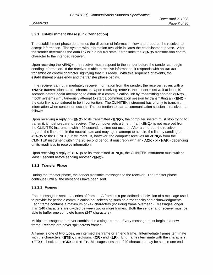
CLINITEK Communication Standard SpecificationDate: April 2, 1998
SS000700 Page 7 of 30
3.2.1 Establishment Phase (Link Connection)
The establishment phase determines the direction of information flow and prepares the receiver toaccept information. The system with information available initiates the establishment phase. Afterthe sender determines the data link is in a neutral state, it transmits the <ENQ> transmission controlcharacter to the intended receiver.
Upon receiving the <ENQ>, the receiver must respond to the sender before the sender can beginsending information. If the receiver is able to receive information, it responds with an <ACK>transmission control character signifying that it is ready. With this sequence of events, theestablishment phase ends and the transfer phase begins.
If the receiver cannot immediately receive information from the sender, the receiver replies with a<NAK> transmission control character. Upon receiving <NAK>, the sender must wait at least 10seconds before again attempting to establish a communication link by transmitting another <ENQ>.If both systems simultaneously attempt to start a communication session by transmitting an <ENQ>,the data link is considered to be in contention. The CLINITEK instrument has priority to transmitinformation when contention occurs. The contention to start a communication session is resolved asfollows:
Upon receiving a reply of <ENQ> to its transmitted <ENQ>, the computer system must stop trying totransmit; it must prepare to receive. The computer sets a timer. If an <ENQ> is not received fromthe CLINITEK instrument within 20 seconds, a time-out occurs. After a time-out, the receiverregards the line to be in the neutral state and may again attempt to acquire the line by sending an<ENQ> to the CLINITEK instrument. If, however, the computer receives an <ENQ> from theCLINITEK instrument within the 20 second period, it must reply with an <ACK> or <NAK> dependingon its readiness to receive information.
Upon receiving a reply of <ENQ> to its transmitted <ENQ>, the CLINITEK instrument must wait atleast 1 second before sending another <ENQ>.
3.2.2 Transfer Phase
During the transfer phase, the sender transmits messages to the receiver. The transfer phasecontinues until all the messages have been sent.
3.2.2.1 Frames
Each message is sent in a series of frames. A frame is a pre-defined subdivision of a message usedto provide for periodic communication housekeeping such as error checks and acknowledgments. Each frame contains a maximum of 247 characters (including frame overhead). Messages longerthan 240 characters are divided between two or more frames. Both the sender and receiver must beable to buffer one complete frame (247 characters).
Multiple messages are never combined in a single frame. Every message must begin in a newframe. Records are never split across frames.
A frame is one of two types, an intermediate frame or an end frame. Intermediate frames terminatewith the characters <ETB>, checksum, <CR> and <LF>. End frames terminate with the characters<ETX>, checksum, <CR> and <LF>. Messages less than 240 characters may be sent in one end

CLINITEK Communication Standard SpecificationDate: April 2, 1998
SS000700 Page 8 of 30
frame. Longer messages are sent in intermediate frames with the last part of the message sent in anend frame.
The frame structure is as follows:
<STX> FN text <ETB> C1 C2 <CR> <LF> <-- intermediate frame..<STX> FN text <ETX> C1 C2 <CR> <LF> <-- end frame
where:
<STX> Start of Text transmission control characterFN single digit Frame Number 0 to 7text Data Content of Message<ETB> End of Transmission Block transmission control character<ETX> End of Text transmission control characterC1 most significant character of checksum 0 to 9 and A to FC2 least significant character of checksum 0 to 9 and A to F<CR> Carriage Return ASCII character<LF> Line Feed ASCII character
3.2.2.2 Frame Number
The frame number allows the receiver to distinguish between new and retransmitted frames. IT is asingle digit sent immediately after the <STX> character.
The frame number is an ASCII digit ranging from 0 to 7. The frame number begins at 1 with the firstframe of the Transfer phase. The frame number is incremented by one for every new frametransmitted. After 7, the frame number rolls over to 0, and continues in this fashion.
3.2.2.3 Checksum
The checksum permits the receiver to detect a defective frame. The checksum is encoded as twocharacters which are sent after the <ETB> or <ETX> character. The checksum is computed byadding the binary values of the characters, keeping the least significant eight bits of the sum.
The checksum is initialized to zero with the <STX> character. The first character used in computingthe checksum is the frame number. Each character in the message text is added to the checksum(modulo 256). The computation for the checksum does not include <STX>, the checksumcharacters, or the trailing <CR> and <LF>.
The checksum is an integer represented by eight bits, it can be considered as two groups of four bits.The groups of four bits are converted to the ASCII characters of the hexadecimal representation. The two ASCII characters are transmitted as the checksum, with the most significant character first.
For example, a checksum of 122 can be represented as 01111010 in binary or 7A in hexadecimal. The checksum is transmitted as the ASCII character 7 followed by the character A.
3.2.2.4 Acknowledgments
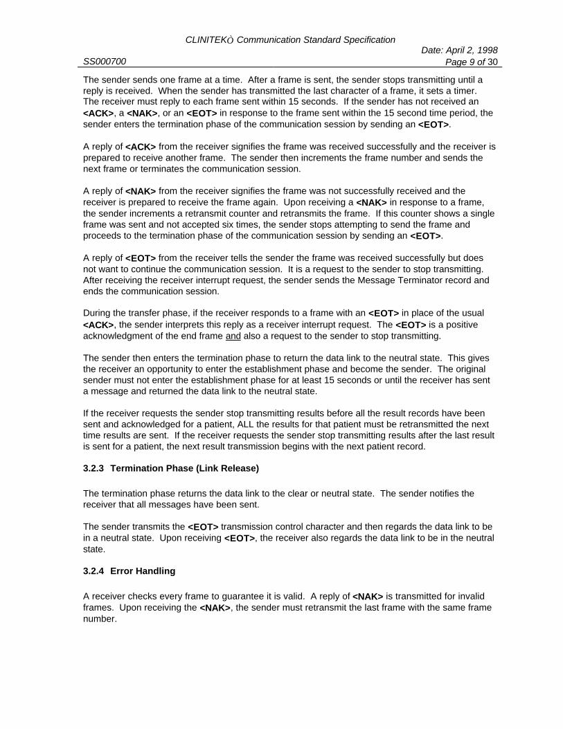
CLINITEK Communication Standard SpecificationDate: April 2, 1998
SS000700 Page 9 of 30
The sender sends one frame at a time. After a frame is sent, the sender stops transmitting until areply is received. When the sender has transmitted the last character of a frame, it sets a timer. The receiver must reply to each frame sent within 15 seconds. If the sender has not received an<ACK>, a <NAK>, or an <EOT> in response to the frame sent within the 15 second time period, thesender enters the termination phase of the communication session by sending an <EOT>.
A reply of <ACK> from the receiver signifies the frame was received successfully and the receiver isprepared to receive another frame. The sender then increments the frame number and sends thenext frame or terminates the communication session.
A reply of <NAK> from the receiver signifies the frame was not successfully received and thereceiver is prepared to receive the frame again. Upon receiving a <NAK> in response to a frame,the sender increments a retransmit counter and retransmits the frame. If this counter shows a singleframe was sent and not accepted six times, the sender stops attempting to send the frame andproceeds to the termination phase of the communication session by sending an <EOT>.
A reply of <EOT> from the receiver tells the sender the frame was received successfully but doesnot want to continue the communication session. It is a request to the sender to stop transmitting. After receiving the receiver interrupt request, the sender sends the Message Terminator record andends the communication session.
During the transfer phase, if the receiver responds to a frame with an <EOT> in place of the usual<ACK>, the sender interprets this reply as a receiver interrupt request. The <EOT> is a positiveacknowledgment of the end frame and also a request to the sender to stop transmitting.
The sender then enters the termination phase to return the data link to the neutral state. This givesthe receiver an opportunity to enter the establishment phase and become the sender. The originalsender must not enter the establishment phase for at least 15 seconds or until the receiver has senta message and returned the data link to the neutral state.
If the receiver requests the sender stop transmitting results before all the result records have beensent and acknowledged for a patient, ALL the results for that patient must be retransmitted the nexttime results are sent. If the receiver requests the sender stop transmitting results after the last resultis sent for a patient, the next result transmission begins with the next patient record.
3.2.3 Termination Phase (Link Release)
The termination phase returns the data link to the clear or neutral state. The sender notifies thereceiver that all messages have been sent.
The sender transmits the <EOT> transmission control character and then regards the data link to bein a neutral state. Upon receiving <EOT>, the receiver also regards the data link to be in the neutralstate.
3.2.4 Error Handling
A receiver checks every frame to guarantee it is valid. A reply of <NAK> is transmitted for invalidframes. Upon receiving the <NAK>, the sender must retransmit the last frame with the same framenumber.
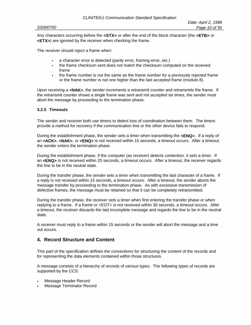
CLINITEK Communication Standard SpecificationDate: April 2, 1998
SS000700 Page 10 of 30
Any characters occurring before the <STX> or after the end of the block character (the <ETB> or<ETX>) are ignored by the receiver when checking the frame.
The receiver should reject a frame when:
• a character error is detected (parity error, framing error, etc.)• the frame checksum sent does not match the checksum computed on the received
frame• the frame number is not the same as the frame number for a previously rejected frame
or the frame number is not one higher than the last accepted frame (modulo 8).
Upon receiving a <NAK>, the sender increments a retransmit counter and retransmits the frame. Ifthe retransmit counter shows a single frame was sent and not accepted six times, the sender mustabort the message by proceeding to the termination phase.
3.2.5 Timeouts
The sender and receiver both use timers to detect loss of coordination between them. The timersprovide a method for recovery if the communication line or the other device fails to respond. During the establishment phase, the sender sets a timer when transmitting the <ENQ>. If a reply ofan <ACK>, <NAK>, or <ENQ> is not received within 15 seconds, a timeout occurs. After a timeout,the sender enters the termination phase.
During the establishment phase, if the computer (as receiver) detects contention, it sets a timer. Ifan <ENQ> is not received within 20 seconds, a timeout occurs. After a timeout, the receiver regardsthe line to be in the neutral state.
During the transfer phase, the sender sets a timer when transmitting the last character of a frame. Ifa reply is not received within 15 seconds, a timeout occurs. After a timeout, the sender aborts themessage transfer by proceeding to the termination phase. As with excessive transmission ofdefective frames, the message must be retained so that it can be completely retransmitted.
During the transfer phase, the receiver sets a timer when first entering the transfer phase or whenreplying to a frame. If a frame or <EOT> is not received within 30 seconds, a timeout occurs. Aftera timeout, the receiver discards the last incomplete message and regards the line to be in the neutralstate.
A receiver must reply to a frame within 15 seconds or the sender will abort the message and a timeout occurs.
4. Record Structure and Content
This part of the specification defines the conventions for structuring the content of the records andfor representing the data elements contained within those structures.
A message consists of a hierarchy of records of various types. The following types of records aresupported by the CCS:
• Message Header Record• Message Terminator Record

CLINITEK Communication Standard SpecificationDate: April 2, 1998
SS000700 Page 11 of 30
• Request Information Record• Order Record• Patient Record• Result Record• Comment Record• Manufacturer Record All message data is represented as eight bit values within the range (0-126) as defined by the ASCIIstandard (ANSI X3.4-1986). None of the ten transmission control characters, the <CR> and <LF>format control characters, or four device control characters may appear in message text. The CCSformat also reserves the <BEL>character. The restricted characters are:
Character ASCII Value HEX Value<SOH> 001 01<STX> 002 02<ETX> 003 03<EOT> 004 04<ENQ> 005 05<ACK> 006 06<BEL> 007 07<LF> 010 0A<CR> 013 0D<DLE> 016 10<DC1> 017 11<DC2> 018 12<DC3> 019 13<DC4> 020 14<NAK> 021 15<SYN> 022 16<ETB> 023 17
Within text data fields, only the ASCII characters 32-126 are permitted as usable characters with theexception of those characters used as delimiter characters. All characters used as delimiters areexcluded from the permitted range. The sender is responsible for screening all text data fields toensure that the text does not contain those delimiters. The contents of the data fields is casesensitive.
Fields are identified by their position within a record. The position is obtained by counting field delimitersfrom the front of the record. This position-sensitive identification process requires that when the contentsof the field are null, its corresponding field delimiter must be included in the record to ensure that the ithfield can be found by counting (i-1) delimiters. Delimiters are not included for trailing null fields; that is, ifthe tenth field was the last field containing data, the record could terminate after the tenth field, andtherefore would contain only nine delimiters.
The following message delimiters are used for each record:
Delimiter CharacterRepresentation
Definition
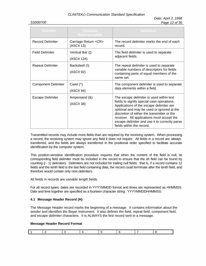
CLINITEK Communication Standard SpecificationDate: April 2, 1998
SS000700 Page 12 of 30
Delimiter CharacterRepresentation
Definition
Record Delimiter Carriage Return <CR>(ASCII 13)
The record delimiter marks the end of eachrecord.
Field Delimiter Vertical Bar (|)
(ASCII 124)
The field delimiter is used to separateadjacent fields.
Repeat Delimiter Backslash (\)
(ASCII 92)
The repeat delimiter is used to separatevariable numbers of descriptors for fieldscontaining parts of equal members of thesame set.
Component Delimiter Caret (^)
(ASCII 94)
The component delimiter is used to separatedata elements within a field.
Escape Delimiter Ampersand (&)
(ASCII 38)
The escape delimiter is used within textfields to signify special case operations. Applications of the escape delimiter areoptional and may be used or ignored at thediscretion of either the transmitter or thereceiver. All applications must accept theescape delimiter and use it to correctly parsefields within the record.
Transmitted records may include more fields than are required by the receiving system. When processinga record, the receiving system may ignore any field it does not require. All fields in a record are always transferred, and the fields are always transferred in the positional order specified to facilitate accurateidentification by the computer system.
This position-sensitive identification procedure requires that when the content of the field is null, itscorresponding field delimiter must be included in the record to ensure that the ith field can be found bycounting (i - 1) delimiters. Delimiters are not included for trailing null fields: that is, if a record contains 12fields and the tenth field is the last field containing data, the record could terminate after the tenth field, andtherefore would contain only nine delimiters.
All fields in records are variable length fields.
For all record types, dates are recorded in YYYYMMDD format and times are represented as HHMMSS.Date and time together are specified as a fourteen character string: YYYYMMDDHHMMSS.
4.1 Message Header Record (H)
The Message Header record marks the beginning of a message. It contains information about thesender and identifies the Bayer instrument. It also defines the field, repeat field, component field,and escape delimiter characters. It is ALWAYS the first record sent in a message.
Message Header Record Format
1 2 3 4 5 6 7 8
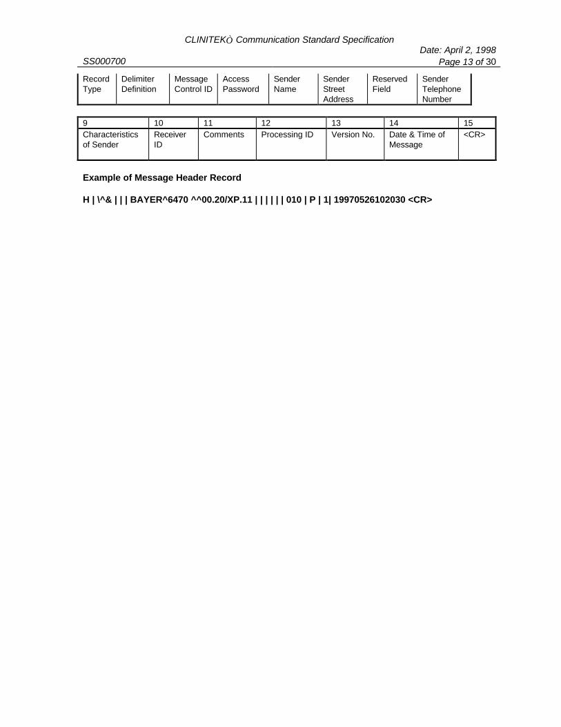
CLINITEK Communication Standard SpecificationDate: April 2, 1998
SS000700 Page 13 of 30
RecordType
DelimiterDefinition
MessageControl ID
AccessPassword
SenderName
SenderStreetAddress
ReservedField
SenderTelephoneNumber
9 10 11 12 13 14 15Characteristicsof Sender
ReceiverID
Comments Processing ID Version No. Date & Time ofMessage
<CR>
Example of Message Header Record
H | \^& | | | BAYER^6470 ^^00.20/XP.11 | | | | | | 010 | P | 1| 19970526102030 <CR>
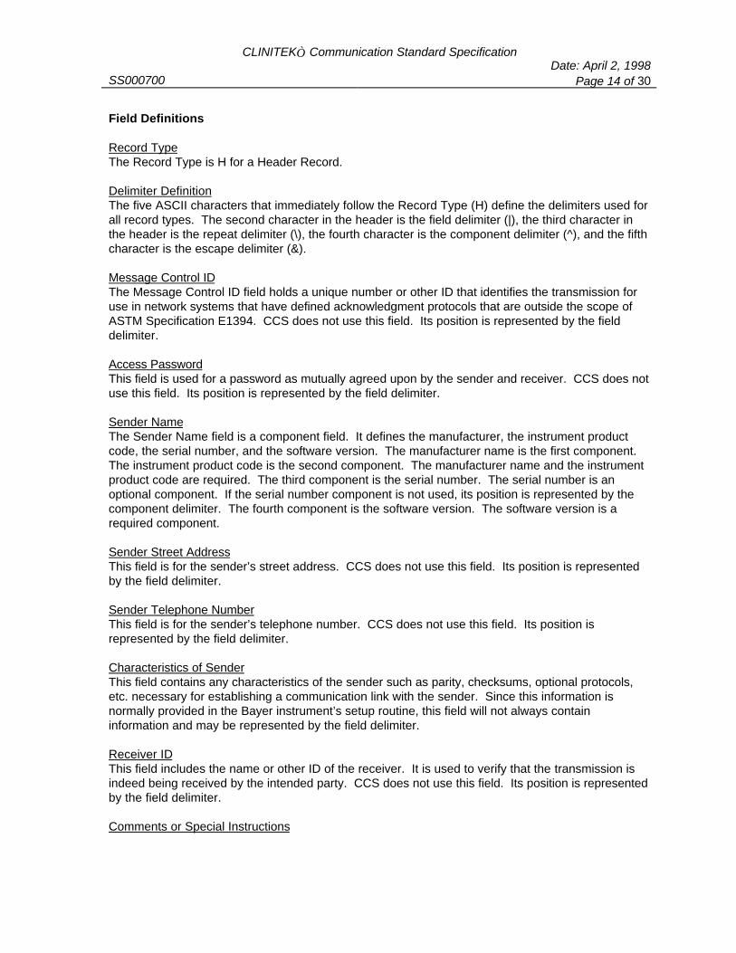
CLINITEK Communication Standard SpecificationDate: April 2, 1998
SS000700 Page 14 of 30
Field Definitions
Record TypeThe Record Type is H for a Header Record.
Delimiter DefinitionThe five ASCII characters that immediately follow the Record Type (H) define the delimiters used forall record types. The second character in the header is the field delimiter (|), the third character inthe header is the repeat delimiter (\), the fourth character is the component delimiter (^), and the fifthcharacter is the escape delimiter (&).
Message Control IDThe Message Control ID field holds a unique number or other ID that identifies the transmission foruse in network systems that have defined acknowledgment protocols that are outside the scope ofASTM Specification E1394. CCS does not use this field. Its position is represented by the fielddelimiter.
Access PasswordThis field is used for a password as mutually agreed upon by the sender and receiver. CCS does notuse this field. Its position is represented by the field delimiter.
Sender NameThe Sender Name field is a component field. It defines the manufacturer, the instrument productcode, the serial number, and the software version. The manufacturer name is the first component. The instrument product code is the second component. The manufacturer name and the instrumentproduct code are required. The third component is the serial number. The serial number is anoptional component. If the serial number component is not used, its position is represented by thecomponent delimiter. The fourth component is the software version. The software version is arequired component.
Sender Street AddressThis field is for the sender’s street address. CCS does not use this field. Its position is representedby the field delimiter.
Sender Telephone NumberThis field is for the sender’s telephone number. CCS does not use this field. Its position isrepresented by the field delimiter.
Characteristics of SenderThis field contains any characteristics of the sender such as parity, checksums, optional protocols,etc. necessary for establishing a communication link with the sender. Since this information isnormally provided in the Bayer instrument’s setup routine, this field will not always containinformation and may be represented by the field delimiter.
Receiver IDThis field includes the name or other ID of the receiver. It is used to verify that the transmission isindeed being received by the intended party. CCS does not use this field. Its position is representedby the field delimiter.
Comments or Special Instructions

CLINITEK Communication Standard SpecificationDate: April 2, 1998
SS000700 Page 15 of 30
This field is a component field. Currently there is one component defined. The first componentcontains the language/result unit code.
Language/Result Unit CodesEnglish Conventional-Normal 010 German SI-Normal 070English Conventional-PLUS System 011 German SI-PLUS System 071English SI-Normal 020 Italian-Normal 080English SI-PLUS System 021 Italian-PLUS System 081English Nordic-Normal 030 Japanese-Normal 090English Nordic-PLUS System 031 Japanese-PLUS System 091French Conventional-Normal 040 Spanish-Normal 100French Conventional-PLUS System 041 Spanish-PLUS System 101French SI-Normal 050 Chinese-Normal 110French SI-PLUS System 051 Chinese-PLUS System 111German Conventional-Normal 060 Portuguese-Normal 120German Conventional-PLUS System 061 Portuguese-PLUS System 121
Processing IDThis field indicates how this message is to be processed:• P for Production: This software has passed all validation criteria and has been production released. The test results
may be relied upon for clinical use.• T for Training: This software has been released for training purposes only. Test results obtained from this software
are not for clinical use.• D for Debugging: This software has been released for debugging/testing purposes only. Test results obtained from this
software are not for clinical use.• Q for Quality Control:
This software has been released for the purpose of obtaining quality assurance or regulatorydata. Although the portions of the software that collect and process the data have beenvalidated, the test results obtained from this software are not for clinical use.
Version NumberThis value identifies the version level of the CLINITEK Communication Standard Specification. This value is currently one (1).
Date and Time of Message TransmissionThis field contains the date and time this header record was sent. The format for this field isYYYYMMDDHHMMSS.
4.2 Message Terminator Record (L)
The Message Terminator record marks the end of the message. It is ALWAYS the last record sent ina message.
Message Terminator Record Format
1 2 3 4Record Record Termination <CR>

CLINITEK Communication Standard SpecificationDate: April 2, 1998
SS000700 Page 16 of 30
Type SequenceNumber
Code
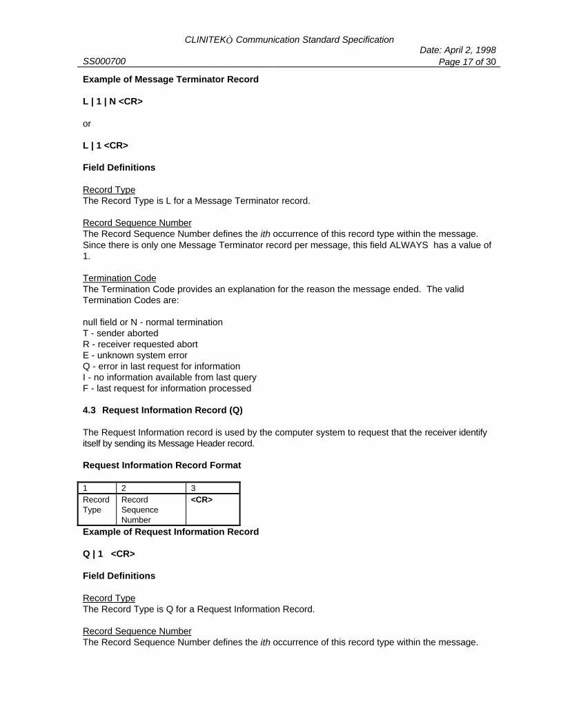
CLINITEK Communication Standard SpecificationDate: April 2, 1998
SS000700 Page 17 of 30
Example of Message Terminator Record
L | 1 | N <CR>
or
L | 1 <CR>
Field Definitions
Record TypeThe Record Type is L for a Message Terminator record.
Record Sequence NumberThe Record Sequence Number defines the ith occurrence of this record type within the message. Since there is only one Message Terminator record per message, this field ALWAYS has a value of1.
Termination CodeThe Termination Code provides an explanation for the reason the message ended. The validTermination Codes are:
null field or N - normal terminationT - sender abortedR - receiver requested abortE - unknown system errorQ - error in last request for informationI - no information available from last queryF - last request for information processed
4.3 Request Information Record (Q)
The Request Information record is used by the computer system to request that the receiver identifyitself by sending its Message Header record.
Request Information Record Format
1 2 3RecordType
RecordSequenceNumber
<CR>
Example of Request Information Record
Q | 1 <CR>
Field Definitions
Record TypeThe Record Type is Q for a Request Information Record.
Record Sequence NumberThe Record Sequence Number defines the ith occurrence of this record type within the message.

CLINITEK Communication Standard SpecificationDate: April 2, 1998
SS000700 Page 18 of 30
4.4 Order Record (O)
The Order record is sent by the computer system to the instrument. It is used to provide theinstrument with a list of sample IDs for which tests will be run. Depending on the instrument, this recordmay also support the inclusion of additional data such as physical descriptions for the color and clarity ofthe sample. If additional information is supported, the Patient Identification field becomes a componentdelimited field with each piece of information separated by the component delimiter. Not all CLINITEKinstruments support the Order record.
Order Record Format
1 2 3 4RecordType
RecordSequenceNumber
PatientIdentification
<CR>
Example of Order Record for Instrument Accepting only ID Information
0 | 1 | 078302465 <CR>
Example of Order Record for Instrument Accepting ID, Color, and Clarity Information
0 | 1 | 078302465^YELLOW^CLEAR <CR>
Field Definitions
Record TypeThe Record Type is O for an Order record.
Record Sequence NumberThe Record Sequence Number defines the ith occurrence of this record type within the message.
Patient IdentificationThe Patient Identification field is a component field. At a minimum, it contains the Sample ID for apatient. If the instrument supports additional information such as sample color and clarity, this fieldis a component delimited field containing all three pieces of information.
4.5 Patient Record (P)
This record contains information about a sample that applies to every Result record for that sample.
Patient Record Format
1 2 3 4 5 6 7 8RecordType
RecordSequenceNumber
TestSequenceNumber
Date and Time Sample ID Tech ID SampleLocation
<CR>
1 2 3 4 5 6 8 9 10
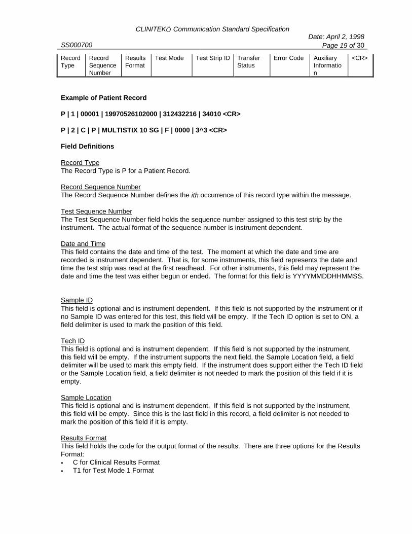
CLINITEK Communication Standard SpecificationDate: April 2, 1998
SS000700 Page 19 of 30
RecordType
RecordSequenceNumber
ResultsFormat
Test Mode Test Strip ID TransferStatus
Error Code AuxiliaryInformation
<CR>
Example of Patient Record
P | 1 | 00001 | 19970526102000 | 312432216 | 34010 <CR>
P | 2 | C | P | MULTISTIX 10 SG | F | 0000 | 3^3 <CR>
Field Definitions
Record TypeThe Record Type is P for a Patient Record.
Record Sequence NumberThe Record Sequence Number defines the ith occurrence of this record type within the message.
Test Sequence NumberThe Test Sequence Number field holds the sequence number assigned to this test strip by theinstrument. The actual format of the sequence number is instrument dependent.
Date and TimeThis field contains the date and time of the test. The moment at which the date and time arerecorded is instrument dependent. That is, for some instruments, this field represents the date andtime the test strip was read at the first readhead. For other instruments, this field may represent thedate and time the test was either begun or ended. The format for this field is YYYYMMDDHHMMSS.
Sample IDThis field is optional and is instrument dependent. If this field is not supported by the instrument or ifno Sample ID was entered for this test, this field will be empty. If the Tech ID option is set to ON, afield delimiter is used to mark the position of this field.
Tech IDThis field is optional and is instrument dependent. If this field is not supported by the instrument, this field will be empty. If the instrument supports the next field, the Sample Location field, a fielddelimiter will be used to mark this empty field. If the instrument does support either the Tech ID fieldor the Sample Location field, a field delimiter is not needed to mark the position of this field if it isempty.
Sample LocationThis field is optional and is instrument dependent. If this field is not supported by the instrument, this field will be empty. Since this is the last field in this record, a field delimiter is not needed tomark the position of this field if it is empty.
Results FormatThis field holds the code for the output format of the results. There are three options for the ResultsFormat:• C for Clinical Results Format• T1 for Test Mode 1 Format
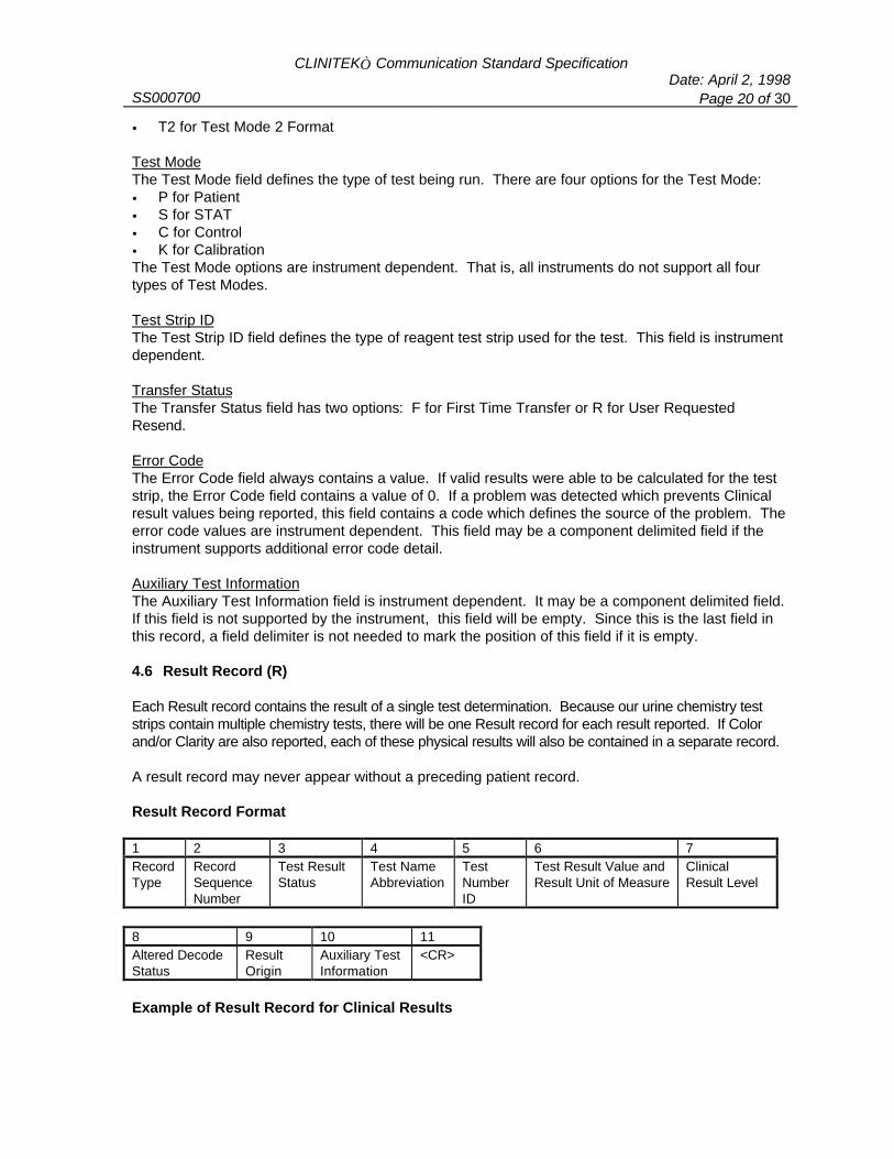
CLINITEK Communication Standard SpecificationDate: April 2, 1998
SS000700 Page 20 of 30
• T2 for Test Mode 2 Format
Test ModeThe Test Mode field defines the type of test being run. There are four options for the Test Mode:• P for Patient• S for STAT• C for Control• K for CalibrationThe Test Mode options are instrument dependent. That is, all instruments do not support all fourtypes of Test Modes.
Test Strip IDThe Test Strip ID field defines the type of reagent test strip used for the test. This field is instrumentdependent.
Transfer StatusThe Transfer Status field has two options: F for First Time Transfer or R for User RequestedResend.
Error CodeThe Error Code field always contains a value. If valid results were able to be calculated for the teststrip, the Error Code field contains a value of 0. If a problem was detected which prevents Clinicalresult values being reported, this field contains a code which defines the source of the problem. Theerror code values are instrument dependent. This field may be a component delimited field if theinstrument supports additional error code detail.
Auxiliary Test InformationThe Auxiliary Test Information field is instrument dependent. It may be a component delimited field.If this field is not supported by the instrument, this field will be empty. Since this is the last field inthis record, a field delimiter is not needed to mark the position of this field if it is empty.
4.6 Result Record (R)
Each Result record contains the result of a single test determination. Because our urine chemistry teststrips contain multiple chemistry tests, there will be one Result record for each result reported. If Colorand/or Clarity are also reported, each of these physical results will also be contained in a separate record.
A result record may never appear without a preceding patient record.
Result Record Format
1 2 3 4 5 6 7RecordType
RecordSequenceNumber
Test ResultStatus
Test NameAbbreviation
TestNumberID
Test Result Value andResult Unit of Measure
ClinicalResult Level
8 9 10 11Altered DecodeStatus
ResultOrigin
Auxiliary TestInformation
<CR>
Example of Result Record for Clinical Results

CLINITEK Communication Standard SpecificationDate: April 2, 1998
SS000700 Page 21 of 30
R | 1 | N | PRO | 6 | 100 ^ mg/dL | 4 | 0 | A <CR>
Example of Result Record for Test Mode 2 Results
R | 1 | N | PRO | 6 | 100 ^ mg/dL | 4 | 0 | A | 413^264^264^200^0639 <CR>
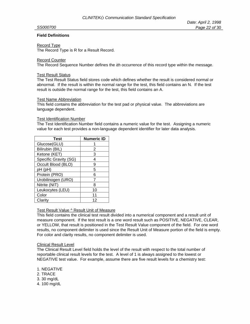
CLINITEK Communication Standard SpecificationDate: April 2, 1998
SS000700 Page 22 of 30
Field Definitions
Record TypeThe Record Type is R for a Result Record.
Record CounterThe Record Sequence Number defines the ith occurrence of this record type within the message.
Test Result StatusThe Test Result Status field stores code which defines whether the result is considered normal orabnormal. If the result is within the normal range for the test, this field contains an N. If the testresult is outside the normal range for the test, this field contains an A.
Test Name AbbreviationThis field contains the abbreviation for the test pad or physical value. The abbreviations arelanguage dependent.
Test Identification NumberThe Test Identification Number field contains a numeric value for the test. Assigning a numericvalue for each test provides a non-language dependent identifier for later data analysis.
Test Numeric IDGlucose(GLU) 1Bilirubin (BIL) 2Ketone (KET) 3Specific Gravity (SG) 4Occult Blood (BLO) 9pH (pH) 5Protein (PRO) 6Urobilinogen (URO) 7Nitrite (NIT) 8Leukocytes (LEU) 10Color 11Clarity 12
Test Result Value ^ Result Unit of MeasureThis field contains the clinical test result divided into a numerical component and a result unit ofmeasure component. If the test result is a one word result such as POSITIVE, NEGATIVE, CLEAR,or YELLOW, that result is positioned in the Test Result Value component of the field. For one wordresults, no component delimiter is used since the Result Unit of Measure portion of the field is empty.For color and clarity results, no component delimiter is used.
Clinical Result LevelThe Clinical Result Level field holds the level of the result with respect to the total number ofreportable clinical result levels for the test. A level of 1 is always assigned to the lowest orNEGATIVE test value. For example, assume there are five result levels for a chemistry test:
1. NEGATIVE2. TRACE3. 30 mg/dL4. 100 mg/dL

CLINITEK Communication Standard SpecificationDate: April 2, 1998
SS000700 Page 23 of 30
5. >=300 mg/dL

CLINITEK Communication Standard SpecificationDate: April 2, 1998
SS000700 Page 24 of 30
Since the value of 100 mg/dL is the 4th result level, the value assigned to the Clinical Result Levelfield would be 4.
Altered Decode StatusThe Altered Decode Status field contains a 0 if altered decodes are not used. This field contains a 1if altered decodes are used.
Result OriginThe Result Origin field contains the code which defines the source of the test result. If the result wascalculated by the Analyzer, the value of this field is A. If the result was manually entered, the valueof this field is M. If the result was edited, the value of this field is E. When Result Records reportClinical Results, this is the last field in the record.
Auxiliary InformationThe Auxiliary Information field is not used for Clinical Result records (Result Records for a PatientRecord with a value of ‘C’ in the Test Mode field). The Auxiliary Information field is used for TestMode records (Result records for a Patient record with a Results Format value of ‘T1’ or ‘T2’). Thisfield is a component delimited field. The content of the field is instrument dependent.
4.7 Comment Record (C)A comment record may follow any record but the Message Terminator record. A comment recordprovides additional information about the previous record. It always relates to the immediatelypreceding record. Not all CLINITEK instruments support the Comment record.
Comment Record Format
1 2 3 4RecordType
RecordSequenceNumber
CommentText
<CR>
Example of Comment Record
C | 1 | This is a comment. <CR>
Field Definitions
Record TypeThe Record Type is C for a Comment Record.
Record Sequence CounterThe Record Sequence Number defines the ith occurrence of this record type within the message.
Comment TextThe Comment Text field is instrument dependent. It is not supported by all instruments.
4.8 Manufacturer Record (M)This record is used to send information for research and development and maintenance use. The contentof the Manufacturer Information field varies by instrument.
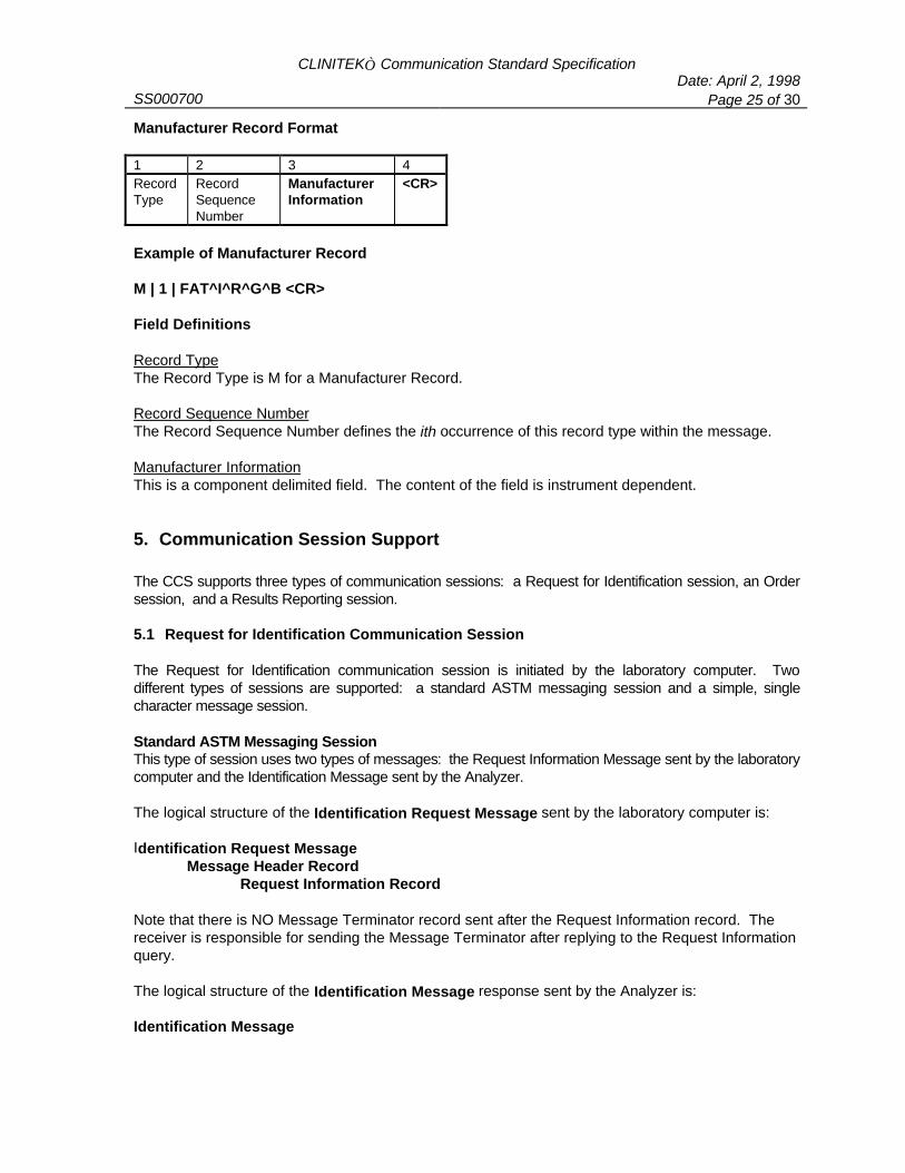
CLINITEK Communication Standard SpecificationDate: April 2, 1998
SS000700 Page 25 of 30
Manufacturer Record Format
1 2 3 4RecordType
RecordSequenceNumber
ManufacturerInformation
<CR>
Example of Manufacturer Record
M | 1 | FAT^I^R^G^B <CR>
Field Definitions
Record TypeThe Record Type is M for a Manufacturer Record.
Record Sequence NumberThe Record Sequence Number defines the ith occurrence of this record type within the message.
Manufacturer InformationThis is a component delimited field. The content of the field is instrument dependent.
5. Communication Session Support
The CCS supports three types of communication sessions: a Request for Identification session, an Ordersession, and a Results Reporting session.
5.1 Request for Identification Communication Session
The Request for Identification communication session is initiated by the laboratory computer. Twodifferent types of sessions are supported: a standard ASTM messaging session and a simple, singlecharacter message session.
Standard ASTM Messaging SessionThis type of session uses two types of messages: the Request Information Message sent by the laboratorycomputer and the Identification Message sent by the Analyzer.
The logical structure of the Identification Request Message sent by the laboratory computer is:
Identification Request MessageMessage Header Record
Request Information Record
Note that there is NO Message Terminator record sent after the Request Information record. Thereceiver is responsible for sending the Message Terminator after replying to the Request Informationquery.
The logical structure of the Identification Message response sent by the Analyzer is:
Identification Message
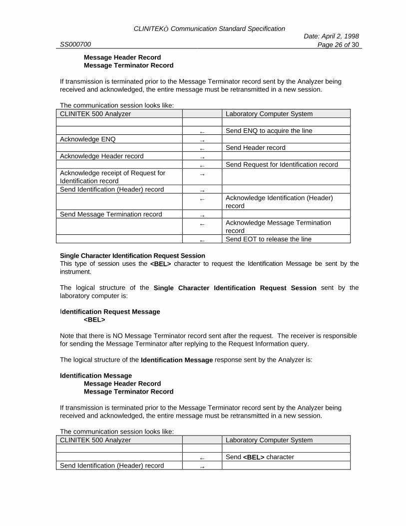
CLINITEK Communication Standard SpecificationDate: April 2, 1998
SS000700 Page 26 of 30
Message Header RecordMessage Terminator Record
If transmission is terminated prior to the Message Terminator record sent by the Analyzer beingreceived and acknowledged, the entire message must be retransmitted in a new session.
The communication session looks like:CLINITEK 500 Analyzer Laboratory Computer System
← Send ENQ to acquire the lineAcknowledge ENQ →
← Send Header recordAcknowledge Header record →
← Send Request for Identification recordAcknowledge receipt of Request forIdentification record
→
Send Identification (Header) record →← Acknowledge Identification (Header)
recordSend Message Termination record →
← Acknowledge Message Terminationrecord
← Send EOT to release the line
Single Character Identification Request SessionThis type of session uses the <BEL> character to request the Identification Message be sent by theinstrument.
The logical structure of the Single Character Identification Request Session sent by thelaboratory computer is:
Identification Request Message<BEL>
Note that there is NO Message Terminator record sent after the request. The receiver is responsiblefor sending the Message Terminator after replying to the Request Information query.
The logical structure of the Identification Message response sent by the Analyzer is:
Identification MessageMessage Header RecordMessage Terminator Record
If transmission is terminated prior to the Message Terminator record sent by the Analyzer beingreceived and acknowledged, the entire message must be retransmitted in a new session.
The communication session looks like:CLINITEK 500 Analyzer Laboratory Computer System
← Send <BEL> characterSend Identification (Header) record →

CLINITEK Communication Standard SpecificationDate: April 2, 1998
SS000700 Page 27 of 30
CLINITEK 500 Analyzer Laboratory Computer System← Acknowledge receipt of Identification
(Header) recordSend Message Termination record →
← Acknowledge receipt of MessageTermination record
← Send EOT to release the line
5.2 Order Communication Session
The Order communication session is initiated by the laboratory computer. This type of session is used tosend information about the samples to be tested to the instrument.
The logical structure of the Order Message sent by the laboratory computer is:
Message HeaderOrder Record 1Order Record 2...Order Record n
Message Terminator
If transmission is terminated prior to the Message Terminator record sent by the laboratory computerbeing received and acknowledged, the entire message may have to be transmitted for someinstruments. For other instruments, the records that were acknowledged may be stored.
The communication session looks like:CLINITEK 500 Analyzer Laboratory Computer System
← Send ENQ to acquire the lineAcknowledge ENQ →
← Send Header recordAcknowledge receipt of Header record →
← Send first Order record.Acknowledge receipt of first Orderrecord
→
← Send second Order recordAcknowledge receipt of second Orderrecord
→
← Send nth Order recordAcknowledge receipt of nth Orderrecord
→
← Send Message Termination recordAcknowledge receipt of MessageTermination record
→
← Send EOT to release the line
5.3 Results Reporting Communication Session

CLINITEK Communication Standard SpecificationDate: April 2, 1998
SS000700 Page 28 of 30
The Results Reporting communication session is initiated by the Analyzer. When the Analyzer has a testresult to send, it is responsible for notifying the laboratory computer system. If the laboratorycomputer system acknowledges the Analyzer, the Analyzer then sends the test results.
The results for a single patient are contained within a message. Each message block contains thepatient and result records for a single specimen. A single specimen’s patient and result records mayspan more than one message block. Multiple patient records are never sent within the same
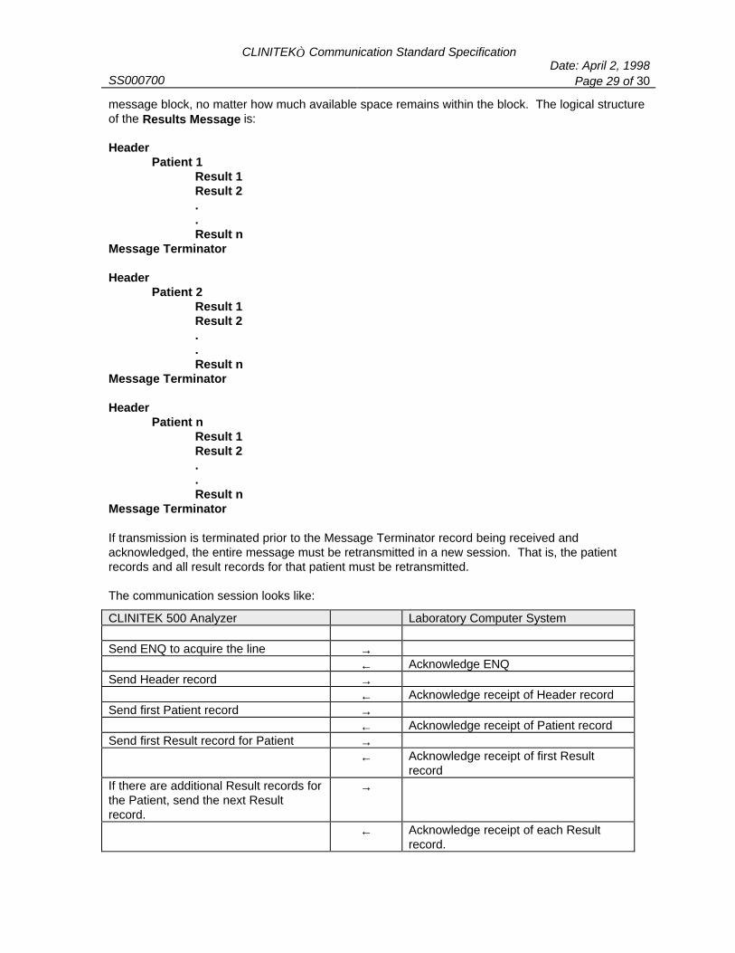
CLINITEK Communication Standard SpecificationDate: April 2, 1998
SS000700 Page 29 of 30
message block, no matter how much available space remains within the block. The logical structureof the Results Message is:
HeaderPatient 1
Result 1Result 2..Result n
Message Terminator
HeaderPatient 2
Result 1Result 2..Result n
Message Terminator
HeaderPatient n
Result 1Result 2..Result n
Message Terminator
If transmission is terminated prior to the Message Terminator record being received andacknowledged, the entire message must be retransmitted in a new session. That is, the patientrecords and all result records for that patient must be retransmitted.
The communication session looks like:
CLINITEK 500 Analyzer Laboratory Computer System
Send ENQ to acquire the line →← Acknowledge ENQ
Send Header record →← Acknowledge receipt of Header record
Send first Patient record →← Acknowledge receipt of Patient record
Send first Result record for Patient →← Acknowledge receipt of first Result
recordIf there are additional Result records forthe Patient, send the next Resultrecord.
→
← Acknowledge receipt of each Resultrecord.

CLINITEK Communication Standard SpecificationDate: April 2, 1998
SS000700 Page 30 of 30
CLINITEK 500 Analyzer Laboratory Computer SystemWhen all the Result records for thispatient have been sent, send theMessage Terminator record.
→
← Acknowledge receipt of MessageTerminator record.
If additional patient records need to bereported, start another message blockby sending ENQ to acquire the line.
→
Send ENQ to acquire the line →← Acknowledge ENQ
Send Header record →← Acknowledge receipt of Header record.
Send next Patient record →← Acknowledge receipt of Patient record
Send first Result record for Patient →← Acknowledge receipt of first Result
recordIf there are additional Result records forthe Patient, send the next Resultrecord.
→
← Acknowledge receipt of each Resultrecord.
When all the Result records for thispatient have been sent, send theMessage Terminator record.
→
← Acknowledge receipt of MessageTerminator record.
When all the patient records andcorresponding result records have beensent, send EOT to release the line andend the session.
→
It is not uncommon for data to be collected from several instruments connected to one computerthrough a multiplexer. Data collection using an ASTM protocol and a multiplexer can become verytime consuming since the multiplexer checks for data port-by-port in a round robin fashion. When aninstrument has sent an <ENQ> to signal that it has data to send, it also sets a timer. The instrumentmust then wait 15 seconds before attempting to contact the computer again. Since the port is notconstantly monitored in a multiplexer setting, it is quite possible that the instrument sends the<ENQ> to acquire the line just prior to the multiplexer returning to that instrument’s port formonitoring. The full 15 seconds will have to pass before the instrument can again send an <ENQ>. The CCS has added support for the <SYN> character to counteract the inherent time delays on amultiplexer port. If the <SYN> character is received by the instrument, the instrument immediatelyresends the <ENQ> and resets its timer. This allows the instrument and computer to establish acommunication session and get a result record sent within the time frame the multiplexer ismonitoring that particular port.
CLINITEK 500 Clinical Results Serial Communication Specification ReturnDate: July 14, 1998
SS000980 Page 1 of 23
CLINITEK 500 Implementationof the
CLINITEK Communication Standardfor Clinical Results Reporting
1. INTRODUCTION ...........................................................................................................................2
2. LOW LEVEL PROTOCOL SUPPORT.........................................................................................2
2.1 CHARACTER STRUCTURE.............................................................................................................22.2 SPEED ........................................................................................................................................2
3. MESSAGE STRUCTURE AND CONTENT..................................................................................2
3.1 MESSAGE HEADER RECORD (H)...................................................................................................33.2 MESSAGE TERMINATOR RECORD (L)............................................................................................53.3 REQUEST INFORMATION RECORD (Q)...........................................................................................63.4 PATIENT RECORD (P) ..................................................................................................................63.5 RESULT RECORD (R) ...................................................................................................................8
4. COMMUNICATION SESSION SUPPORT.................................................................................10
4.1 REQUEST FOR IDENTIFICATION COMMUNICATION SESSION..........................................................104.2 RESULTS REPORTING COMMUNICATION SESSION........................................................................14

CLINITEK 500 Clinical Results Serial Communication SpecificationDate: July 14, 1998
SS000980 Page 2 of 23
1. Introduction
This document provides the CLINITEK 500 Urine Chemistry Analyzer implementation of theCLINITEK Communication Standard, Dwg. SS000700. This document defines the messagecontent for the information that passes between the CLINITEK7 500 Urine Chemistry Analyzerand a laboratory computer. Please refer to the CLINITEK Communication Standard forinformation about data codes, transmission protocol, terminology, and error recovery.
2. Low Level Protocol Support
2.1 Character Structure
The CLINITEK 500 Analyzer supports 7 data bits and even parity, 7 data bits and odd parity, or 8data bits and no parity.
The default character structure consists of 1 start bit, 8 data bits, no parity bit, and 1 stop bit.
2.2 Speed
The data transmission rates supported are 2400, 4800, 9600, and 19200.
The default data transmission rate is 9600 baud.
3. Message Structure and Content
This part of the specification defines the message types supported and the structure of thosemessage types and their supporting records. Each message consists of a hierarchy of records ofvarious types.
When processing a message, the laboratory computer system may ignore any field it does not require.All fields in a record are ALWAYS transferred, and the fields are ALWAYS transferred in the positionalorder specified to facilitate accurate identification by the computer system. All fields in records arevariable length fields.
The following types of records are supported by the CLINITEK 500 Analyzer:Message Header RecordRequest for Identification RecordPatient RecordResult RecordMessage Terminator Record
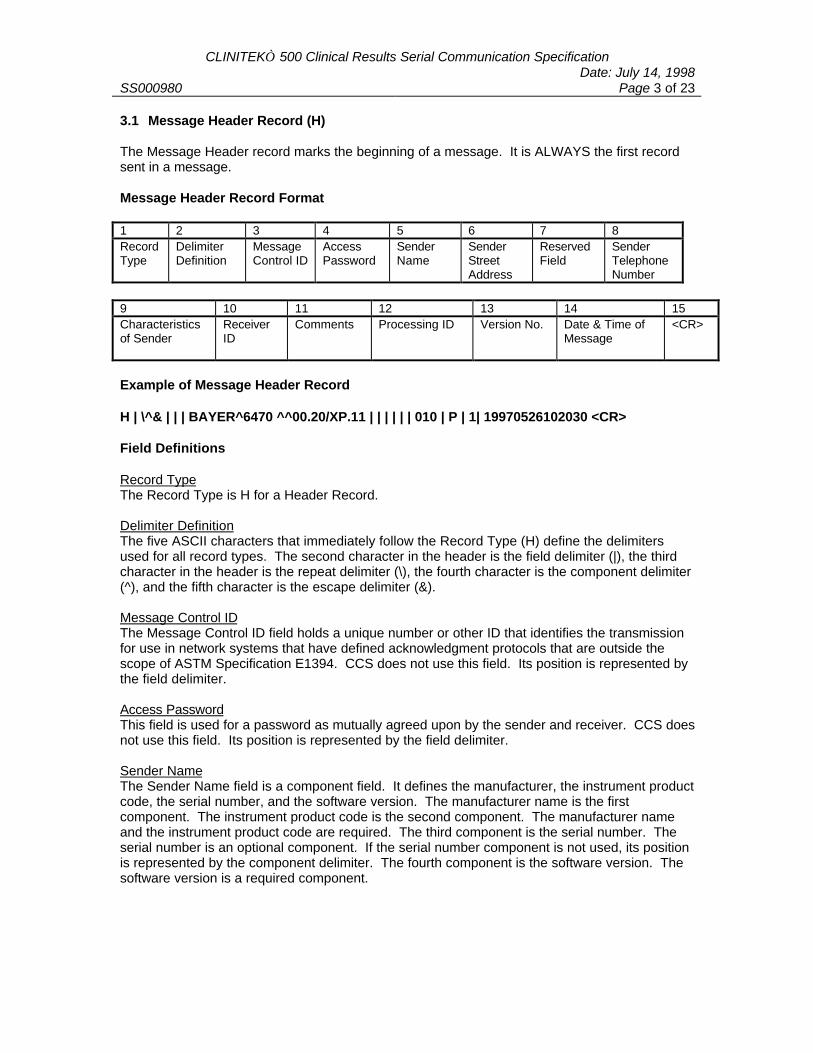
CLINITEK 500 Clinical Results Serial Communication SpecificationDate: July 14, 1998
SS000980 Page 3 of 23
3.1 Message Header Record (H)
The Message Header record marks the beginning of a message. It is ALWAYS the first recordsent in a message.
Message Header Record Format
1 2 3 4 5 6 7 8RecordType
DelimiterDefinition
MessageControl ID
AccessPassword
SenderName
SenderStreetAddress
ReservedField
SenderTelephoneNumber
9 10 11 12 13 14 15Characteristicsof Sender
ReceiverID
Comments Processing ID Version No. Date & Time ofMessage
<CR>
Example of Message Header Record
H | \^& | | | BAYER^6470 ^^00.20/XP.11 | | | | | | 010 | P | 1| 19970526102030 <CR>
Field Definitions
Record TypeThe Record Type is H for a Header Record.
Delimiter DefinitionThe five ASCII characters that immediately follow the Record Type (H) define the delimitersused for all record types. The second character in the header is the field delimiter (|), the thirdcharacter in the header is the repeat delimiter (\), the fourth character is the component delimiter(^), and the fifth character is the escape delimiter (&).
Message Control IDThe Message Control ID field holds a unique number or other ID that identifies the transmissionfor use in network systems that have defined acknowledgment protocols that are outside thescope of ASTM Specification E1394. CCS does not use this field. Its position is represented bythe field delimiter.
Access PasswordThis field is used for a password as mutually agreed upon by the sender and receiver. CCS doesnot use this field. Its position is represented by the field delimiter.
Sender NameThe Sender Name field is a component field. It defines the manufacturer, the instrument productcode, the serial number, and the software version. The manufacturer name is the firstcomponent. The instrument product code is the second component. The manufacturer nameand the instrument product code are required. The third component is the serial number. Theserial number is an optional component. If the serial number component is not used, its positionis represented by the component delimiter. The fourth component is the software version. Thesoftware version is a required component.
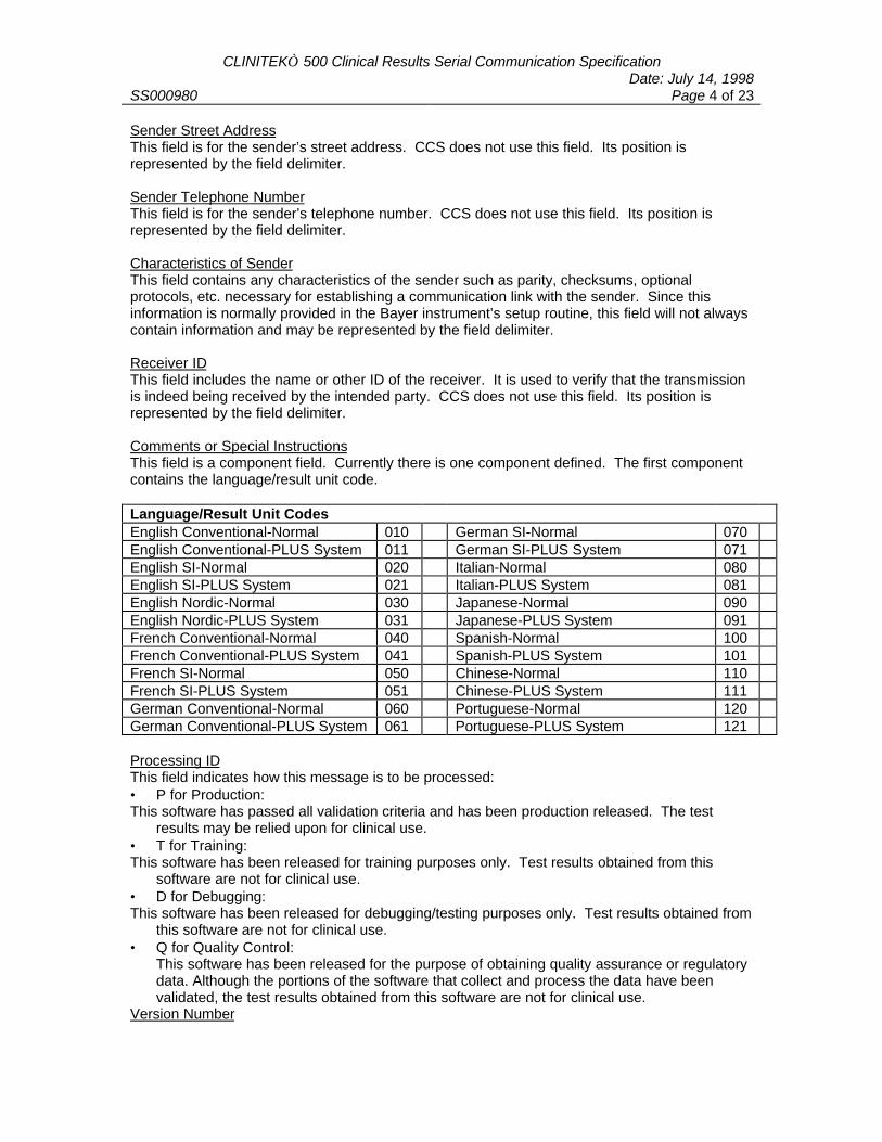
CLINITEK 500 Clinical Results Serial Communication SpecificationDate: July 14, 1998
SS000980 Page 4 of 23
Sender Street AddressThis field is for the sender’s street address. CCS does not use this field. Its position isrepresented by the field delimiter.
Sender Telephone NumberThis field is for the sender’s telephone number. CCS does not use this field. Its position isrepresented by the field delimiter.
Characteristics of SenderThis field contains any characteristics of the sender such as parity, checksums, optionalprotocols, etc. necessary for establishing a communication link with the sender. Since thisinformation is normally provided in the Bayer instrument’s setup routine, this field will not alwayscontain information and may be represented by the field delimiter.
Receiver IDThis field includes the name or other ID of the receiver. It is used to verify that the transmissionis indeed being received by the intended party. CCS does not use this field. Its position isrepresented by the field delimiter.
Comments or Special InstructionsThis field is a component field. Currently there is one component defined. The first componentcontains the language/result unit code.
Language/Result Unit CodesEnglish Conventional-Normal 010 German SI-Normal 070English Conventional-PLUS System 011 German SI-PLUS System 071English SI-Normal 020 Italian-Normal 080English SI-PLUS System 021 Italian-PLUS System 081English Nordic-Normal 030 Japanese-Normal 090English Nordic-PLUS System 031 Japanese-PLUS System 091French Conventional-Normal 040 Spanish-Normal 100French Conventional-PLUS System 041 Spanish-PLUS System 101French SI-Normal 050 Chinese-Normal 110French SI-PLUS System 051 Chinese-PLUS System 111German Conventional-Normal 060 Portuguese-Normal 120German Conventional-PLUS System 061 Portuguese-PLUS System 121
Processing IDThis field indicates how this message is to be processed:• P for Production: This software has passed all validation criteria and has been production released. The test
results may be relied upon for clinical use.• T for Training: This software has been released for training purposes only. Test results obtained from this
software are not for clinical use.• D for Debugging: This software has been released for debugging/testing purposes only. Test results obtained from
this software are not for clinical use.• Q for Quality Control:
This software has been released for the purpose of obtaining quality assurance or regulatorydata. Although the portions of the software that collect and process the data have beenvalidated, the test results obtained from this software are not for clinical use.
Version Number
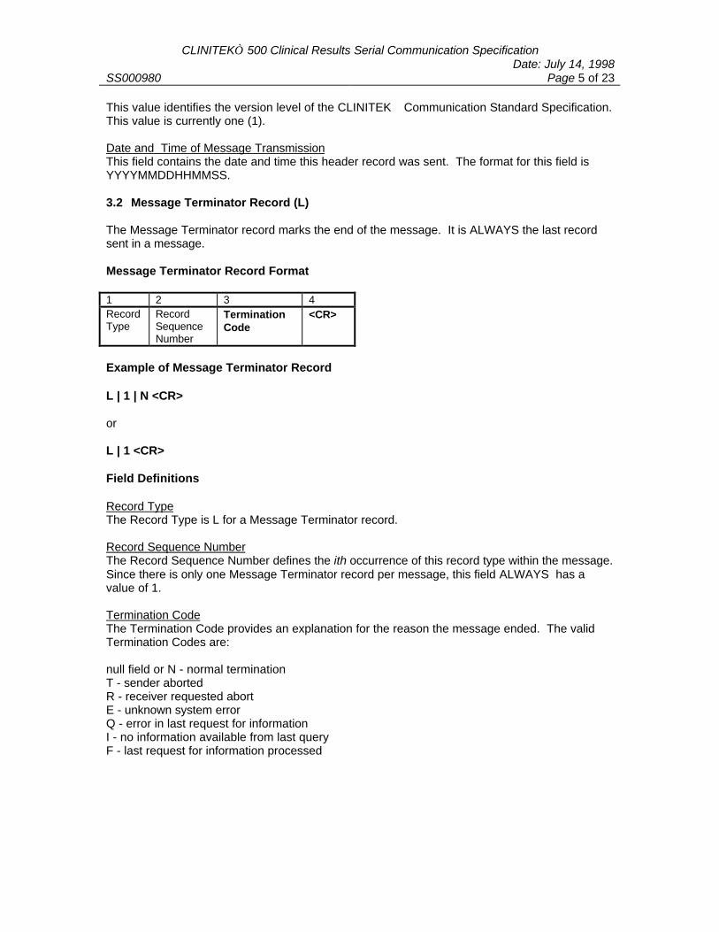
CLINITEK 500 Clinical Results Serial Communication SpecificationDate: July 14, 1998
SS000980 Page 5 of 23
This value identifies the version level of the CLINITEK Communication Standard Specification.This value is currently one (1).
Date and Time of Message TransmissionThis field contains the date and time this header record was sent. The format for this field isYYYYMMDDHHMMSS.
3.2 Message Terminator Record (L)
The Message Terminator record marks the end of the message. It is ALWAYS the last recordsent in a message.
Message Terminator Record Format
1 2 3 4RecordType
RecordSequenceNumber
TerminationCode
<CR>
Example of Message Terminator Record
L | 1 | N <CR>
or
L | 1 <CR>
Field Definitions
Record TypeThe Record Type is L for a Message Terminator record.
Record Sequence NumberThe Record Sequence Number defines the ith occurrence of this record type within the message.Since there is only one Message Terminator record per message, this field ALWAYS has avalue of 1.
Termination CodeThe Termination Code provides an explanation for the reason the message ended. The validTermination Codes are:
null field or N - normal terminationT - sender abortedR - receiver requested abortE - unknown system errorQ - error in last request for informationI - no information available from last queryF - last request for information processed
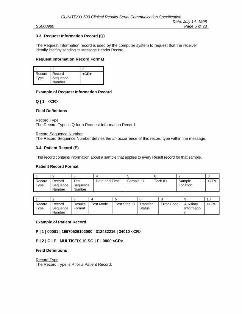
CLINITEK 500 Clinical Results Serial Communication SpecificationDate: July 14, 1998
SS000980 Page 6 of 23
3.3 Request Information Record (Q)
The Request Information record is used by the computer system to request that the receiveridentify itself by sending its Message Header Record.
Request Information Record Format
1 2 3RecordType
RecordSequenceNumber
<CR>
Example of Request Information Record
Q | 1 <CR>
Field Definitions
Record TypeThe Record Type is Q for a Request Information Record.
Record Sequence NumberThe Record Sequence Number defines the ith occurrence of this record type within the message.
3.4 Patient Record (P)
This record contains information about a sample that applies to every Result record for that sample.
Patient Record Format
1 2 3 4 5 6 7 8RecordType
RecordSequenceNumber
TestSequenceNumber
Date and Time Sample ID Tech ID SampleLocation
<CR>
1 2 3 4 5 6 8 9 10RecordType
RecordSequenceNumber
ResultsFormat
Test Mode Test Strip ID TransferStatus
Error Code AuxiliaryInformation
<CR>
Example of Patient Record
P | 1 | 00001 | 19970526102000 | 312432216 | 34010 <CR>
P | 2 | C | P | MULTISTIX 10 SG | F | 0000 <CR>
Field Definitions
Record TypeThe Record Type is P for a Patient Record.
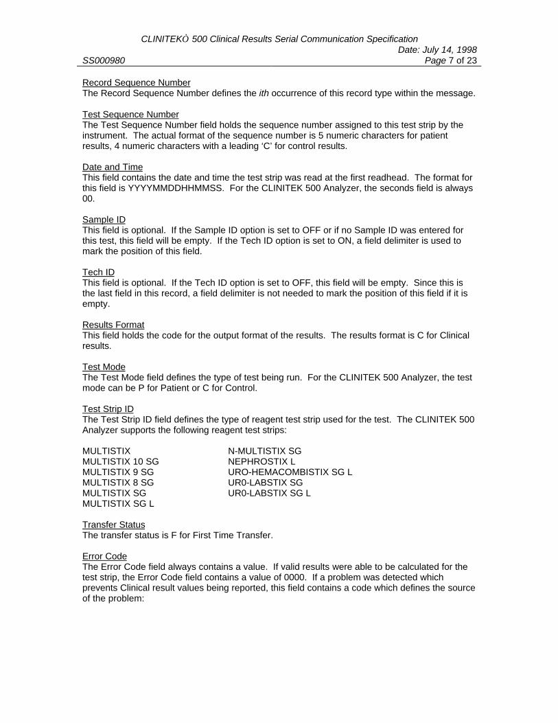
CLINITEK 500 Clinical Results Serial Communication SpecificationDate: July 14, 1998
SS000980 Page 7 of 23
Record Sequence NumberThe Record Sequence Number defines the ith occurrence of this record type within the message.
Test Sequence NumberThe Test Sequence Number field holds the sequence number assigned to this test strip by theinstrument. The actual format of the sequence number is 5 numeric characters for patientresults, 4 numeric characters with a leading ‘C’ for control results.
Date and TimeThis field contains the date and time the test strip was read at the first readhead. The format forthis field is YYYYMMDDHHMMSS. For the CLINITEK 500 Analyzer, the seconds field is always00.
Sample IDThis field is optional. If the Sample ID option is set to OFF or if no Sample ID was entered forthis test, this field will be empty. If the Tech ID option is set to ON, a field delimiter is used tomark the position of this field.
Tech IDThis field is optional. If the Tech ID option is set to OFF, this field will be empty. Since this isthe last field in this record, a field delimiter is not needed to mark the position of this field if it isempty.
Results FormatThis field holds the code for the output format of the results. The results format is C for Clinicalresults.
Test ModeThe Test Mode field defines the type of test being run. For the CLINITEK 500 Analyzer, the testmode can be P for Patient or C for Control.
Test Strip IDThe Test Strip ID field defines the type of reagent test strip used for the test. The CLINITEK 500Analyzer supports the following reagent test strips:
MULTISTIX N-MULTISTIX SGMULTISTIX 10 SG NEPHROSTIX LMULTISTIX 9 SG URO-HEMACOMBISTIX SG LMULTISTIX 8 SG UR0-LABSTIX SGMULTISTIX SG UR0-LABSTIX SG LMULTISTIX SG L
Transfer StatusThe transfer status is F for First Time Transfer.
Error CodeThe Error Code field always contains a value. If valid results were able to be calculated for thetest strip, the Error Code field contains a value of 0000. If a problem was detected whichprevents Clinical result values being reported, this field contains a code which defines the sourceof the problem:

CLINITEK 500 Clinical Results Serial Communication SpecificationDate: July 14, 1998
SS000980 Page 8 of 23
Error CodeReadhead 1 Readhead 2
Low Dark Value 0100 0001High Dark Value 0200 0002A-D Converter Over-range 0300 0003Low Lamp(s) Level 0400 0004Low Channel Output 0500 0005Missing Strip N/A 0006Upside Down/Dry Strip 0700 N/AMisaligned Strip 0800 0008Skewed Strip 0900 0009Reflectance > 100% 1000 0010Auto Strip Type Error 2000 N/A
The error code field may contain a value which represents multiple errors. For example, if a lowdark value was detected under readhead 1 and a skewed strip was detected when the stripreached readhead 2, the error code reported would be 0109.
Auxiliary Test InformationNot transmitted in clinical mode.
3.5 Result Record (R)
Each Result record contains the result of a single test determination. Because our urine chemistry teststrips contain multiple chemistry tests, there will be one Result record for each result reported. If Colorand/or Clarity are also reported, each of these physical results will also be contained in a separaterecord.
A result record may never appear without a preceding patient record.
Result Record Format
1 2 3 4 5 6 7RecordType
RecordSequenceNumber
Test ResultStatus
Test NameAbbreviation
TestNumberID
Test Result Value andResult Unit of Measure
ClinicalResult Level
8 9 10 11Altered DecodeStatus
ResultOrigin
Auxiliary TestInformation
<CR>
Example of Result Record for Clinical Results
R | 1 | N | PRO | 6 | 100 ^ mg/dL | 4 | 0 | A <CR>

CLINITEK 500 Clinical Results Serial Communication SpecificationDate: July 14, 1998
SS000980 Page 9 of 23
Example of Result Record for Test Mode Results
R | 1 | N | PRO | 6 | 100 ^ mg/dL | 4 | 0 | A | 413^264^264^200^0639 <CR>
Field Definitions
Record TypeThe Record Type is R for a Result Record.
Record CounterThe Record Sequence Number defines the ith occurrence of this record type within the message.
Test Result StatusThe Test Result Status field stores code which defines whether the result is considered normal orabnormal. If the result is within the normal range for the test, this field contains an N. If the testresult is outside the normal range for the test, this field contains an A.
Test Name AbbreviationThis field contains the abbreviation for the test pad or physical value. The abbreviations arelanguage dependent.
Test Identification NumberThe Test Identification Number field contains a numeric value for the test. Assigning a numericvalue for each test provides a non-language dependent identifier for later data analysis.
Test Numeric IDGlucose(GLU) 1Bilirubin (BIL) 2Ketone (KET) 3Specific Gravity (SG) 4Occult Blood (BLO) 9pH (pH) 5Protein (PRO) 6Urobilinogen (URO) 7Nitrite (NIT) 8Leukocytes (LEU) 10Color 11Clarity 12
Test Result Value ^ Result Unit of MeasureThis field contains the clinical test result divided into a numerical component and a result unit ofmeasure component. If the test result is a one word result such as POSITIVE, NEGATIVE,CLEAR, or YELLOW, that result is positioned in the Test Result Value component of the field.For one word results, no component delimiter is used since the Result Unit of Measure portion ofthe field is empty. For color and clarity results, no component delimiter is used.
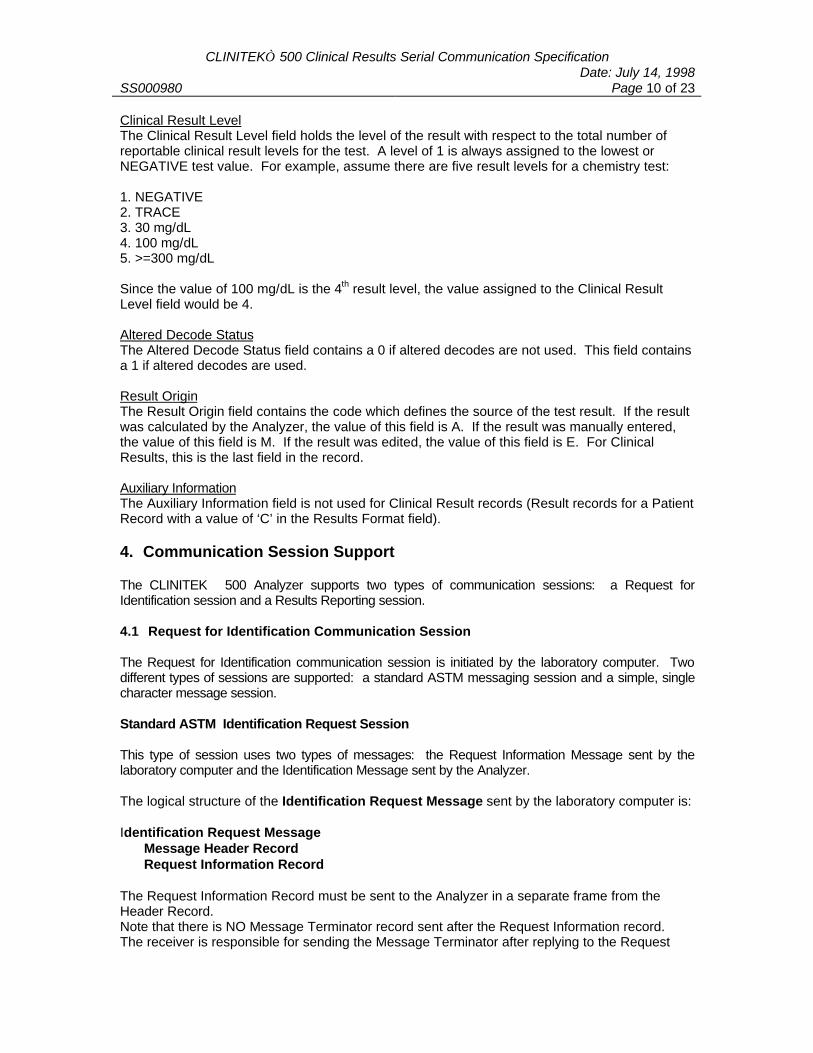
CLINITEK 500 Clinical Results Serial Communication SpecificationDate: July 14, 1998
SS000980 Page 10 of 23
Clinical Result LevelThe Clinical Result Level field holds the level of the result with respect to the total number ofreportable clinical result levels for the test. A level of 1 is always assigned to the lowest orNEGATIVE test value. For example, assume there are five result levels for a chemistry test:
1. NEGATIVE2. TRACE3. 30 mg/dL4. 100 mg/dL5. >=300 mg/dL
Since the value of 100 mg/dL is the 4th result level, the value assigned to the Clinical ResultLevel field would be 4.
Altered Decode StatusThe Altered Decode Status field contains a 0 if altered decodes are not used. This field containsa 1 if altered decodes are used.
Result OriginThe Result Origin field contains the code which defines the source of the test result. If the resultwas calculated by the Analyzer, the value of this field is A. If the result was manually entered,the value of this field is M. If the result was edited, the value of this field is E. For ClinicalResults, this is the last field in the record.
Auxiliary InformationThe Auxiliary Information field is not used for Clinical Result records (Result records for a PatientRecord with a value of ‘C’ in the Results Format field).
4. Communication Session Support
The CLINITEK 500 Analyzer supports two types of communication sessions: a Request forIdentification session and a Results Reporting session.
4.1 Request for Identification Communication Session
The Request for Identification communication session is initiated by the laboratory computer. Twodifferent types of sessions are supported: a standard ASTM messaging session and a simple, singlecharacter message session.
Standard ASTM Identification Request Session
This type of session uses two types of messages: the Request Information Message sent by thelaboratory computer and the Identification Message sent by the Analyzer.
The logical structure of the Identification Request Message sent by the laboratory computer is:
Identification Request MessageMessage Header RecordRequest Information Record
The Request Information Record must be sent to the Analyzer in a separate frame from theHeader Record.Note that there is NO Message Terminator record sent after the Request Information record.The receiver is responsible for sending the Message Terminator after replying to the Request
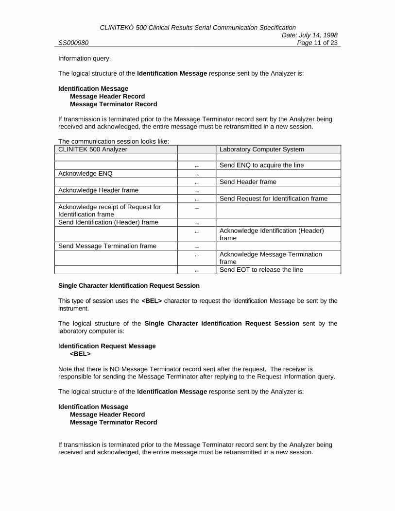
CLINITEK 500 Clinical Results Serial Communication SpecificationDate: July 14, 1998
SS000980 Page 11 of 23
Information query.
The logical structure of the Identification Message response sent by the Analyzer is:
Identification MessageMessage Header RecordMessage Terminator Record
If transmission is terminated prior to the Message Terminator record sent by the Analyzer beingreceived and acknowledged, the entire message must be retransmitted in a new session.
The communication session looks like:CLINITEK 500 Analyzer Laboratory Computer System
← Send ENQ to acquire the lineAcknowledge ENQ →
← Send Header frameAcknowledge Header frame →
← Send Request for Identification frameAcknowledge receipt of Request forIdentification frame
→
Send Identification (Header) frame →← Acknowledge Identification (Header)
frameSend Message Termination frame →
← Acknowledge Message Terminationframe
← Send EOT to release the line
Single Character Identification Request Session
This type of session uses the <BEL> character to request the Identification Message be sent by theinstrument.
The logical structure of the Single Character Identification Request Session sent by thelaboratory computer is:
Identification Request Message<BEL>
Note that there is NO Message Terminator record sent after the request. The receiver isresponsible for sending the Message Terminator after replying to the Request Information query.
The logical structure of the Identification Message response sent by the Analyzer is:
Identification MessageMessage Header RecordMessage Terminator Record
If transmission is terminated prior to the Message Terminator record sent by the Analyzer beingreceived and acknowledged, the entire message must be retransmitted in a new session.
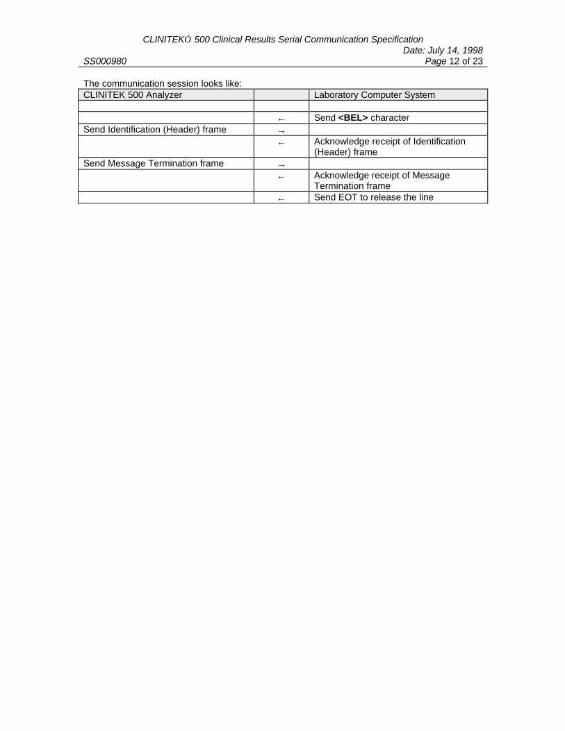
CLINITEK 500 Clinical Results Serial Communication SpecificationDate: July 14, 1998
SS000980 Page 12 of 23
The communication session looks like:CLINITEK 500 Analyzer Laboratory Computer System
← Send <BEL> characterSend Identification (Header) frame →
← Acknowledge receipt of Identification(Header) frame
Send Message Termination frame →← Acknowledge receipt of Message
Termination frame← Send EOT to release the line
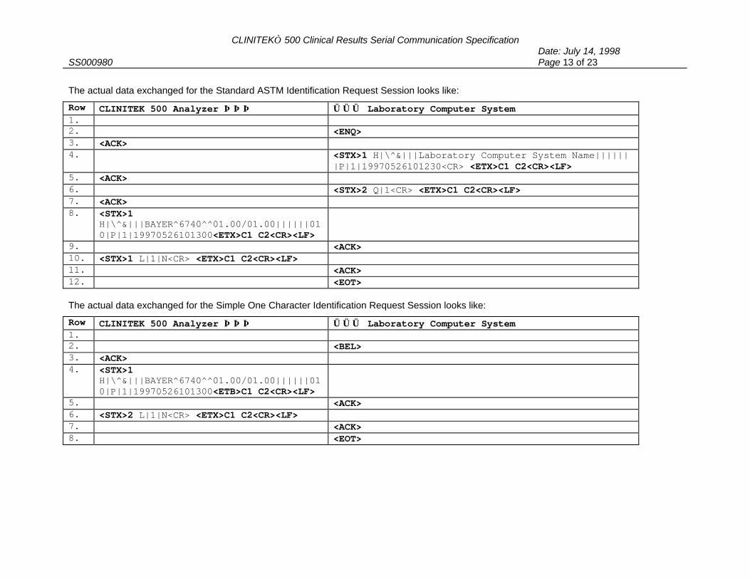
CLINITEK 500 Clinical Results Serial Communication SpecificationDate: July 14, 1998
SS000980 Page 13 of 23
The actual data exchanged for the Standard ASTM Identification Request Session looks like:
Row CLINITEK 500 Analyzer ⇒⇒⇒ ⇐⇐⇐ Laboratory Computer System1. 2. <ENQ>3. <ACK>4. <STX>1 H|\^&|||Laboratory Computer System Name||||||
|P|1|19970526101230<CR> <ETX>C1 C2<CR><LF>5. <ACK>6. <STX>2 Q|1<CR> <ETX>C1 C2<CR><LF>7. <ACK>8. <STX>1
H|\^&|||BAYER^6740^^01.00/01.00||||||010|P|1|19970526101300<ETX>C1 C2<CR><LF>
9. <ACK>10. <STX>1 L|1|N<CR> <ETX>C1 C2<CR><LF>11. <ACK>12. <EOT>
The actual data exchanged for the Simple One Character Identification Request Session looks like:
Row CLINITEK 500 Analyzer ⇒⇒⇒ ⇐⇐⇐ Laboratory Computer System1. 2. <BEL>3. <ACK>4. <STX>1
H|\^&|||BAYER^6740^^01.00/01.00||||||010|P|1|19970526101300<ETB>C1 C2<CR><LF>
5. <ACK>6. <STX>2 L|1|N<CR> <ETX>C1 C2<CR><LF>7. <ACK>8. <EOT>

CLINITEK 500 Clinical Results Serial Communication SpecificationDate: July 14, 1998
SS000980 Page 14 of 23
4.2 Results Reporting Communication Session
The Results Reporting communication session is initiated by the Analyzer. When the Analyzer has atest result to send, it is responsible for notifying the laboratory computer system. If thelaboratory computer system acknowledges the Analyzer, the Analyzer then sends the testresults.
The logical structure of the Results Message is:
HeaderPatient 1
Result 1Result 2..Result n
Message Terminator
HeaderPatient 2
Result 1Result 2..Result n
Message Terminator
HeaderPatient n
Result 1.Result n
Message Terminator
If transmission is terminated prior to the Message Terminator record being received andacknowledged, the entire message must be retransmitted in a new session. That is, the patientrecords and all result records for that patient must be retransmitted.
The communication session looks like:
CLINITEK 500 Analyzer Laboratory Computer System
Send ENQ to acquire the line →← Acknowledge ENQ
Send Header frame →← Acknowledge receipt of Header frame
Send first Patient frame →← Acknowledge receipt of Patient frame
Send first Result frame for Patient →← Acknowledge receipt of first Result
frameIf there are additional Result frames forthe Patient, send the next Result frame.
→

CLINITEK 500 Clinical Results Serial Communication SpecificationDate: July 14, 1998
SS000980 Page 15 of 23
CLINITEK 500 Analyzer Laboratory Computer System← Acknowledge receipt of each Result
frame.When all the Result frames for thispatient have been sent, send theMessage Terminator frame.
→
← Acknowledge receipt of MessageTerminator frame.
If additional patient frames need to bereported, start another message blockby sending ENQ to acquire the line.
→
Send ENQ to acquire the line →← Acknowledge ENQ
Send Header frame →← Acknowledge receipt of Header frame.
Send next Patient frame →← Acknowledge receipt of Patient frame
Send first Result frame for Patient →← Acknowledge receipt of first Result
frameIf there are additional Result frames forthe Patient, send the next Result frame.
→
← Acknowledge receipt of each Resultframe.
When all the Result frames for thispatient have been sent, send theMessage Terminator frame.
→
← Acknowledge receipt of MessageTerminator frame.
When all the patient frames andcorresponding result frames have beensent, send EOT to release the line andend the session.
→
To illustrate the transfer of data from the CLINITEK 500 Analyzer to a laboratory computersystem, assume the urine chemistry test type is MULTISTIX 10 SG and Color is reported, butClarity is not reported. Assume all chemistry tests on the strip are reported. If three tests wererun, the results would be printed as:
00001 05-26-97 10:25 AMTech ID: 323ID: 312445446 COL YELLOW* GLU 250 mg/dL BIL NEGATIVE !KET NEGATIVE SG <=1.005* BLO SMALL pH 6.0 PRO NEGATIVE URO 1.0 E.U./dL NIT NEGATIVE* LEU TRACE

CLINITEK 500 Clinical Results Serial Communication SpecificationDate: July 14, 1998
SS000980 Page 16 of 23
00002 05-26-97 10:25 AMTech ID: 323ID: 213543331 COL YELLOW GLU NEGATIVE BIL NEGATIVE KET NEGATIVE SG <=1.005 BLO NEGATIVE pH 5.5 PRO NEGATIVE URO 0.2 E.U./dL NIT NEGATIVE LEU NEGATIVE
00003 05-26-97 10:25 AMTech ID: 323ID: 398576435* COL RED GLU NEGATIVE BIL NEGATIVE KET NEGATIVE SG <=1.005* BLO MODERATE pH 6.0 PRO NEGATIVE URO 1.0 E.U./dL NIT NEGATIVE* LEU LARGE
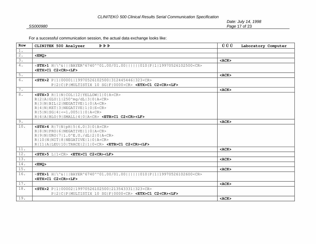
CLINITEK 500 Clinical Results Serial Communication SpecificationDate: July 14, 1998
SS000980 Page 17 of 23
For a successful communication session, the actual data exchange looks like:
Row CLINITEK 500 Analyzer ⇒⇒⇒ ⇐⇐⇐ Laboratory Computer1. 2. <ENQ>3. <ACK>4. <STX>1 H|\^&|||BAYER^6740^^01.00/01.00||||||010|P|1|19970526102500<CR>
<ETX>C1 C2<CR><LF>5. <ACK>6. <STX>2 P|1|00001|19970526102500|312445446|323<CR>
P|2|C|P|MULTISTIX 10 SG|F|0000<CR> <ETX>C1 C2<CR><LF>7. <ACK>8. <STX>3 R|1|N|COL|12|YELLOW|1|0|A<CR>
R|2|A|GLU|1|250^mg/dL|3|0|A<CR>R|3|N|BIL|2|NEGATIVE|1|0|A<CR>R|4|N|KET|3|NEGATIVE|1|0|E<CR>R|5|N|SG|4|<=1.005|1|0|A<CR>R|6|A|BLO|9|SMALL|4|0|A<CR> <ETB>C1 C2<CR><LF>
9. <ACK>10. <STX>4 R|7|N|pH|5|6.0|3|0|A<CR>
R|8|N|PRO|6|NEGATIVE|1|0|A<CR>R|9|N|URO|7|1.0^E.U./dL|2|0|A<CR>R|10|N|NIT|8|NEGATIVE|1|0|A<CR>R|11|A|LEU|10|TRACE|2|1|0<CR> <ETB>C1 C2<CR><LF>
11. <ACK>12. <STX>5 L|1<CR> <ETX>C1 C2<CR><LF>13. <ACK>14. <ENQ>15. <ACK>16. <STX>1 H|\^&|||BAYER^6740^^01.00/01.00||||||010|P|1|19970526102600<CR>
<ETX>C1 C2<CR><LF>17. <ACK>18. <STX>2 P|1|00002|19970526102500|213543331|323<CR>
P|2|C|P|MULTISTIX 10 SG|F|0000<CR> <ETX>C1 C2<CR><LF>19. <ACK>

CLINITEK 500 Clinical Results Serial Communication SpecificationDate: July 14, 1998
SS000980 Page 18 of 23
Row CLINITEK 500 Analyzer ⇒⇒⇒ ⇐⇐⇐ Laboratory Computer20. <STX>3 R|1|N|COL|12|YELLOW|1|0|A<CR>
R|2|N|GLU|1|NEGATIVE|1|0|A<CR>R|3|N|BIL|2|NEGATIVE|1|0|A<CR>R|4|N|KET|3|NEGATIVE|1|0|E<CR>R|5|N|SG|4|<=1.005|1|0|A<CR>R|6|N|BLO|9|NEGATIVE|1|0|A<CR><ETB> C1 C2<CR><LF>
21. <ACK>22. <STX>4 R|7|N|pH|5|5.5|2|0|A<CR>
R|8|N|PRO|6|NEGATIVE|1|0|A<CR>R|9|N|URO|7|0.2^E.U./dL|1|0|A<CR>R|10|N|NIT|8|NEGATIVE|1|0|A<CR>R|11|N|LEU|10|NEGATIVE|1|0|A<CR><ETB>C1 C2<CR><LF>
23. <ACK>24. <STX>5 L|1<CR> <ETX>C1 C2<CR><LF>25. <ENQ>26. <ACK>27. <STX>1 H|\^&|||BAYER^6740^^1.00/01.00||||||010|P|1|19970526102500<CR>
<ETX>C1 C2<CR><LF>28. <ACK>29. <STX>2 P|1|00003|19970526102500|398576435|323<CR>
P|2|C|P|MULTISTIX 10 SG|F|0000<CR> <ETX>C1 C2<CR><LF>30. <ACK>31. <STX>3 R|1|A|COL|12|RED|3|1|A<CR>
R|2|N|GLU|1|NEGATIVE|1|1|A<CR>R|3|N|BIL|2|NEGATIVE|1|1|A<CR>R|4|N|KET|3|NEGATIVE|1|1|A<CR>R|5|N|SG|4|<=1.005|1|1|A<CR>R|6|A|BLO|9|MODERATE|4|1|A<CR><ETB> C1 C2<CR><LF>
32. <ACK>
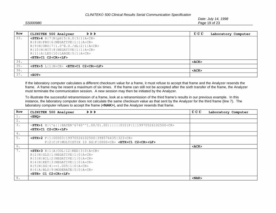
CLINITEK 500 Clinical Results Serial Communication SpecificationDate: July 14, 1998
SS000980 Page 19 of 23
Row CLINITEK 500 Analyzer ⇒⇒⇒ ⇐⇐⇐ Laboratory Computer33. <STX>4 R|7|N|pH|5|6.0|3|1|A<CR>
R|8|N|PRO|6|NEGATIVE|1|1|A<CR>R|9|N|URO|7|1.0^E.U./dL|2|1|A<CR>R|10|N|NIT|8|NEGATIVE|1|1|A<CR>R|11|A|LEU|10|LARGE|5|1|A<CR><ETB>C1 C2<CR><LF>
34. <ACK>35. <STX>5 L|1|N<CR> <ETX>C1 C2<CR><LF>36. <ACK>37. <EOT>
If the laboratory computer calculates a different checksum value for a frame, it must refuse to accept that frame and the Analyzer resends theframe. A frame may be resent a maximum of six times. If the frame can still not be accepted after the sixth transfer of the frame, the Analyzermust terminate the communication session. A new session may then be initiated by the Analyzer.
To illustrate the successful retransmission of a frame, look at a retransmission of the third frame’s results in our previous example. In thisinstance, the laboratory computer does not calculate the same checksum value as that sent by the Analyzer for the third frame (line 7). Thelaboratory computer refuses to accept the frame (<NAK>), and the Analyzer resends that frame.
Row CLINITEK 500 Analyzer ⇒⇒⇒ ⇐⇐⇐ Laboratory Computer1. <ENQ>2. 3. <STX>1 H|\^&|||BAYER^6740^^1.00/01.00||||||010|P|1|19970526102500<CR>
<ETX>C1 C2<CR><LF>4. 5. <STX>2 P|1|00003|19970526102500|398576435|323<CR>
P|2|C|P|MULTISTIX 10 SG|F|0000<CR> <ETX>C1 C2<CR><LF>6. <ACK>7. <STX>3 R|1|A|COL|12|RED|3|0|A<CR>
R|2|N|GLU|1|NEGATIVE|1|0|A<CR>R|3|N|BIL|2|NEGATIVE|1|0|A<CR>R|4|N|KET|3|NEGATIVE|1|0|A<CR>R|5|N|SG|4|<=1.005|1|0|A<CR>R|6|A|BLO|9|MODERATE|5|0|A<CR><ETB> C1 C2<CR><LF>
8. <NAK>
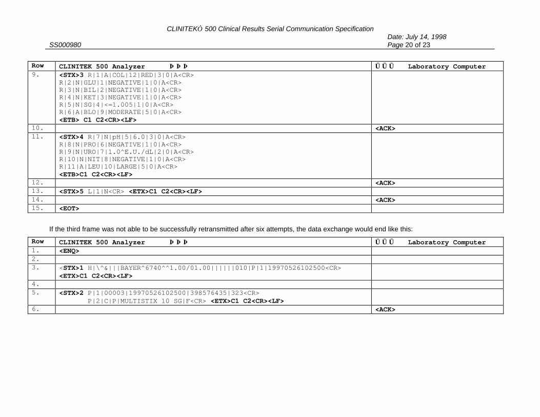
CLINITEK 500 Clinical Results Serial Communication SpecificationDate: July 14, 1998
SS000980 Page 20 of 23
Row CLINITEK 500 Analyzer ⇒⇒⇒ ⇐⇐⇐ Laboratory Computer9. <STX>3 R|1|A|COL|12|RED|3|0|A<CR>
R|2|N|GLU|1|NEGATIVE|1|0|A<CR>R|3|N|BIL|2|NEGATIVE|1|0|A<CR>R|4|N|KET|3|NEGATIVE|1|0|A<CR>R|5|N|SG|4|<=1.005|1|0|A<CR>R|6|A|BLO|9|MODERATE|5|0|A<CR><ETB> C1 C2<CR><LF>
10. <ACK>11. <STX>4 R|7|N|pH|5|6.0|3|0|A<CR>
R|8|N|PRO|6|NEGATIVE|1|0|A<CR>R|9|N|URO|7|1.0^E.U./dL|2|0|A<CR>R|10|N|NIT|8|NEGATIVE|1|0|A<CR>R|11|A|LEU|10|LARGE|5|0|A<CR><ETB>C1 C2<CR><LF>
12. <ACK>13. <STX>5 L|1|N<CR> <ETX>C1 C2<CR><LF>14. <ACK>15. <EOT>
If the third frame was not able to be successfully retransmitted after six attempts, the data exchange would end like this:
Row CLINITEK 500 Analyzer ⇒⇒⇒ ⇐⇐⇐ Laboratory Computer1. <ENQ>2. 3. <STX>1 H|\^&|||BAYER^6740^^1.00/01.00||||||010|P|1|19970526102500<CR>
<ETX>C1 C2<CR><LF>4. 5. <STX>2 P|1|00003|19970526102500|398576435|323<CR>
P|2|C|P|MULTISTIX 10 SG|F<CR> <ETX>C1 C2<CR><LF>6. <ACK>
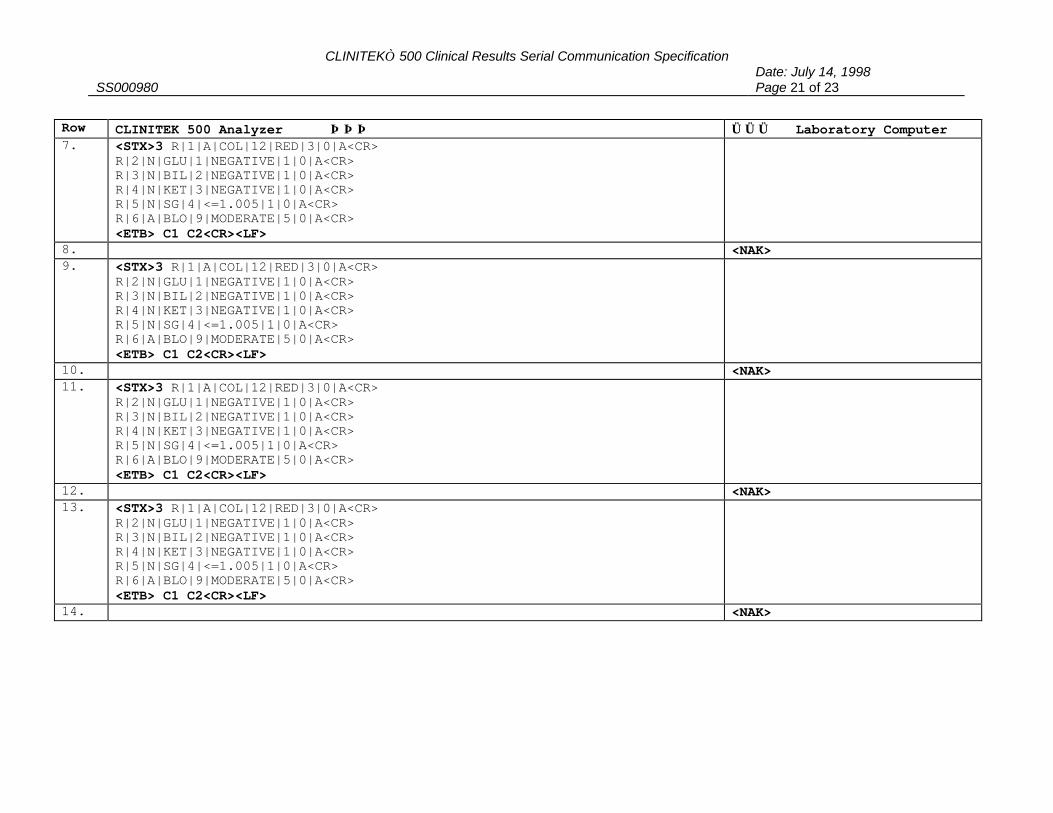
CLINITEK 500 Clinical Results Serial Communication SpecificationDate: July 14, 1998
SS000980 Page 21 of 23
Row CLINITEK 500 Analyzer ⇒⇒⇒ ⇐⇐⇐ Laboratory Computer7. <STX>3 R|1|A|COL|12|RED|3|0|A<CR>
R|2|N|GLU|1|NEGATIVE|1|0|A<CR>R|3|N|BIL|2|NEGATIVE|1|0|A<CR>R|4|N|KET|3|NEGATIVE|1|0|A<CR>R|5|N|SG|4|<=1.005|1|0|A<CR>R|6|A|BLO|9|MODERATE|5|0|A<CR><ETB> C1 C2<CR><LF>
8. <NAK>9. <STX>3 R|1|A|COL|12|RED|3|0|A<CR>
R|2|N|GLU|1|NEGATIVE|1|0|A<CR>R|3|N|BIL|2|NEGATIVE|1|0|A<CR>R|4|N|KET|3|NEGATIVE|1|0|A<CR>R|5|N|SG|4|<=1.005|1|0|A<CR>R|6|A|BLO|9|MODERATE|5|0|A<CR><ETB> C1 C2<CR><LF>
10. <NAK>11. <STX>3 R|1|A|COL|12|RED|3|0|A<CR>
R|2|N|GLU|1|NEGATIVE|1|0|A<CR>R|3|N|BIL|2|NEGATIVE|1|0|A<CR>R|4|N|KET|3|NEGATIVE|1|0|A<CR>R|5|N|SG|4|<=1.005|1|0|A<CR>R|6|A|BLO|9|MODERATE|5|0|A<CR><ETB> C1 C2<CR><LF>
12. <NAK>13. <STX>3 R|1|A|COL|12|RED|3|0|A<CR>
R|2|N|GLU|1|NEGATIVE|1|0|A<CR>R|3|N|BIL|2|NEGATIVE|1|0|A<CR>R|4|N|KET|3|NEGATIVE|1|0|A<CR>R|5|N|SG|4|<=1.005|1|0|A<CR>R|6|A|BLO|9|MODERATE|5|0|A<CR><ETB> C1 C2<CR><LF>
14. <NAK>
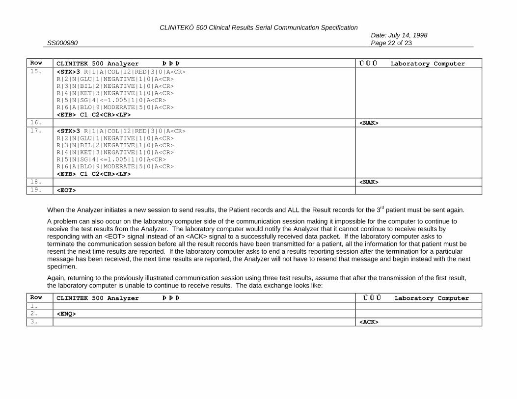
CLINITEK 500 Clinical Results Serial Communication SpecificationDate: July 14, 1998
SS000980 Page 22 of 23
Row CLINITEK 500 Analyzer ⇒⇒⇒ ⇐⇐⇐ Laboratory Computer15. <STX>3 R|1|A|COL|12|RED|3|0|A<CR>
R|2|N|GLU|1|NEGATIVE|1|0|A<CR>R|3|N|BIL|2|NEGATIVE|1|0|A<CR>R|4|N|KET|3|NEGATIVE|1|0|A<CR>R|5|N|SG|4|<=1.005|1|0|A<CR>R|6|A|BLO|9|MODERATE|5|0|A<CR><ETB> C1 C2<CR><LF>
16. <NAK>17. <STX>3 R|1|A|COL|12|RED|3|0|A<CR>
R|2|N|GLU|1|NEGATIVE|1|0|A<CR>R|3|N|BIL|2|NEGATIVE|1|0|A<CR>R|4|N|KET|3|NEGATIVE|1|0|A<CR>R|5|N|SG|4|<=1.005|1|0|A<CR>R|6|A|BLO|9|MODERATE|5|0|A<CR><ETB> C1 C2<CR><LF>
18. <NAK>19. <EOT>
When the Analyzer initiates a new session to send results, the Patient records and ALL the Result records for the 3rd patient must be sent again.
A problem can also occur on the laboratory computer side of the communication session making it impossible for the computer to continue toreceive the test results from the Analyzer. The laboratory computer would notify the Analyzer that it cannot continue to receive results byresponding with an <EOT> signal instead of an <ACK> signal to a successfully received data packet. If the laboratory computer asks toterminate the communication session before all the result records have been transmitted for a patient, all the information for that patient must beresent the next time results are reported. If the laboratory computer asks to end a results reporting session after the termination for a particularmessage has been received, the next time results are reported, the Analyzer will not have to resend that message and begin instead with the nextspecimen.
Again, returning to the previously illustrated communication session using three test results, assume that after the transmission of the first result,the laboratory computer is unable to continue to receive results. The data exchange looks like:
Row CLINITEK 500 Analyzer ⇒⇒⇒ ⇐⇐⇐ Laboratory Computer1. 2. <ENQ>3. <ACK>

CLINITEK 500 Clinical Results Serial Communication SpecificationDate: July 14, 1998
SS000980 Page 23 of 23
Row CLINITEK 500 Analyzer ⇒⇒⇒ ⇐⇐⇐ Laboratory Computer4. <STX>1 H|\^&|||BAYER^6740^^1.00/01.00||||||010|P|1|19970526102500<CR>
<ETX>C1 C2<CR><LF>5. <ACK>6. <STX>2 P|1|00001|19970526102502|312445446|323<CR>
P|2|C|P|MULTISTIX 8|F|0000<CR> <ETX>C1 C2<CR><LF>7. <ACK>8. <STX>3 R|1|N|COL|12|YELLOW|1|1|A<CR>
R|2|A|GLU|1|250^mg/dL|3|1|A<CR>R|3|N|BIL|2|NEGATIVE|1|1|A<CR>R|4|N|KET|3|NEGATIVE|1|1|E<CR>R|5|N|SG|4|<=1.005|1|1|A<CR>R|6|A|BLO|9|SMALL|4|1|A<CR><ETB>C1 C2<CR><LF>
9. <ACK>10. <STX>4 R|7|N|pH|5|6.0|3|1|A<CR>
R|8|N|PRO|6|NEGATIVE|1|1|A<CR>R|9|N|URO|7|1.0^E.U./dL|2|1|A<CR>R|10|N|NIT|8|NEGATIVE|1|1|A<CR>R|11|A|LEU|10|TRACE|2|1|A<CR> <ETB>C1 C2<CR><LF>
11. <ACK>12. <EOT>
The instrument must wait at least 15 seconds before attempting to take control of the line again and send additional results. When the instrumentdoes send an <ENQ> and receives a reply of <ACK> from the laboratory computer, the instrument will send the next set of results.
Recommended